

Page 1

RS507/RS507X
Hands-Free Imager
Product Reference Guide
72E-120802-06
Page 2

Copyright
© 2020 ZIH Corp. and/or its affiliates. All rights reserved. ZEBRA and the stylized Zebra head are trademarks of
ZIH Corp., registered in many jurisdictions worldwide. All other trademarks are the property of their respective
owners.
COPYRIGHTS & TRADEMARKS: For complete copyright and trademark information, go to www.zebra.com/
copyright.
WARRANTY: For complete warranty information, go to www.zebra.com/warranty.
END USER LICENSE AGREEMENT: For complete EULA information, go to www.zebra.com/eula.
Terms of Use
• Proprietary Statement
This manual contains proprietary information of Zebra Technologies Corporation and its subsidiaries
(“Zebra Technologies”). It is intended solely for the information and use of parties operating and
maintaining the equipment described herein. Such proprietary information may not be used, reproduced,
or disclosed to any other parties for any other purpose without the express, written permission of Zebra
Technologies.
• Product Improvements
Continuous improvement of products is a policy of Zebra Technologies. All specifications and designs are
subject to change without notice.
• Liability Disclaimer
Zebra Technologies takes steps to ensure that its published Engineering specifications and manuals are
correct; however, errors do occur. Zebra Technologies reserves the right to correct any such errors and
disclaims liability resulting therefrom.
• Limitation of Liability
In no event shall Zebra Technologies or anyone else involved in the creation, production, or delivery of the
accompanying product (including hardware and software) be liable for any damages whatsoever
(including, without limitation, consequential damages including loss of business profits, business
interruption, or loss of business information) arising out of the use of, the results of use of, or inability to
use such product, even if Zebra Technologies has been advised of the possibility of such damages. Some
jurisdictions do not allow the exclusion or limitation of incidental or consequential damages, so the above
limitation or exclusion may not apply to you.
Revision History
Changes to the original guide are listed below:
Change Date Description
-06 Rev A 12/2020 Replaced master/slave references with central/peripheral
-05 Rev A 5/2018 Add Image Capture mode and HID Features for Apple iOS (HID only)
-04 Rev A 11/2017 Add model number RS507X
2
Page 3

Change Date Description
-03 Rev A 4/2017 Correct LED indicator indications in Table 2.
-02 Rev A 3/2015 Zebra rebranding
-01 Rev B 10/2011 Add Chapter 7
-01 Rev A 10/2009 Release
3
Page 4

Table of Contents
Copyright ........................................................................................................................................... 2
Terms of Use .................................................................................................................................... 2
Revision History ................................................................................................................................ 2
About This Guide
Introduction ..................................................................................................................................... 12
Documentation Set ......................................................................................................................... 12
Model Configurations ...................................................................................................................... 12
Chapter Descriptions ...................................................................................................................... 13
Notational Conventions ................................................................................................................... 13
Related Documents ........................................................................................................................ 14
Service Information ......................................................................................................................... 14
Provide Documentation Feedback .................................................................................................. 14
Getting Started
Introduction ..................................................................................................................................... 15
RS507 Hands-Free Imager Features .............................................................................................. 15
Unpacking ....................................................................................................................................... 16
Cordless Configuration Features .................................................................................................... 17
Corded Configuration Features ....................................................................................................... 18
Trigger Swivel Assembly - Change Trigger Position ................................................................. 19
Getting Started - Cordless Configuration ........................................................................................ 20
Charge the Battery .................................................................................................................... 20
Install the Battery ...................................................................................................................... 20
Remove the Battery .................................................................................................................. 20
Wearing the Imager ................................................................................................................... 20
Getting Started - Corded Configuration .......................................................................................... 21
Connect the Corded Adapter .................................................................................................... 21
Remove the Corded Adapter .................................................................................................... 22
Connect to a WT4XXX Wearable Terminal ............................................................................... 22
Wearing the Imager ................................................................................................................... 23
Status Indications ............................................................................................................................ 23
Imager Standby Mode ..................................................................................................................... 25
Bluetooth Connection ...................................................................................................................... 25
Establish Bluetooth Connection ................................................................................................ 25
Restore Lost Bluetooth Connection .......................................................................................... 27
4
Page 5

Table of Contents
Remove Bluetooth Connection ................................................................................................. 27
Pairing Bar Code Format .......................................................................................................... 28
Scan ................................................................................................................................................ 28
Scan Triggering Modes ............................................................................................................. 28
Aiming the Imager ..................................................................................................................... 29
Customize the Imager ..................................................................................................................... 30
Changing from Triggered to Triggerless Configuration ............................................................. 30
Changing Triggerless to Triggered Configuration ..................................................................... 30
Resetting the Imager ....................................................................................................................... 31
Warm Boot ................................................................................................................................ 31
Cold Boot .................................................................................................................................. 31
Clean Boot ................................................................................................................................ 31
SAC5070 8-Bay Battery Charger
Introduction ..................................................................................................................................... 32
Unpacking the Charger ................................................................................................................... 32
Parts of the Charger ........................................................................................................................ 33
Installation ....................................................................................................................................... 34
Tabletop / Shelf Set Up ............................................................................................................. 34
Wall Mount ................................................................................................................................ 34
Inserting the Imager Battery in the Charger .................................................................................... 35
Charge the Battery .................................................................................................................... 36
Battery Age Test ............................................................................................................................. 36
Charge Status LED ................................................................................................................... 37
Troubleshooting & Maintenance
Introduction ..................................................................................................................................... 38
Troubleshooting .............................................................................................................................. 38
Imager ....................................................................................................................................... 38
Charger ..................................................................................................................................... 39
Maintenance ................................................................................................................................... 40
Maintaining the Imager ................................................................................................................... 40
Comfort Pad Replacement ........................................................................................................ 40
Trigger Swivel Assembly Replacement ..................................................................................... 41
Triggerless Strap Holder Replacement ..................................................................................... 42
Finger Strap Replacement (Trigger Swivel Assembly) ............................................................. 43
Finger Strap Replacement (Triggerless Strap Holder) .............................................................. 44
Strap Buckle Replacement ........................................................................................................ 45
Field Replaceable Parts ............................................................................................................ 45
Cleaning the Imager .................................................................................................................. 46
Maintaining the Charger .................................................................................................................. 47
Operating conditions for the Charger ........................................................................................ 47
Handling the Charger ................................................................................................................ 47
Cleaning the Charger ................................................................................................................ 47
RS507 Update and Configuration
Introduction ..................................................................................................................................... 48
Configuring the Imager ................................................................................................................... 48
5
Page 6

Table of Contents
Introduction ............................................................................................................................... 48
Control Panel Application .......................................................................................................... 49
RSMSample Application ........................................................................................................... 50
Imager Attributes ....................................................................................................................... 53
Imager Motion and Proximity Configuration .............................................................................. 57
.................................................................................................................................................. 61
Real Time Logger ........................................................................................................................... 61
Imager Firmware Update ................................................................................................................ 62
Required Equipment ................................................................................................................. 62
Updating the RS507 Firmware .................................................................................................. 62
Miscellaneous Imager Options
Introduction ..................................................................................................................................... 66
Scanning Sequence Examples ....................................................................................................... 66
Errors While Scanning .................................................................................................................... 67
User Preferences/Miscellaneous Options Parameter Defaults ....................................................... 67
User Preferences ............................................................................................................................ 68
Set Default Parameter ............................................................................................................... 68
Parameter Bar Code Scanning ................................................................................................. 69
Beep After Good Decode .......................................................................................................... 69
Beeper Tone ............................................................................................................................. 70
Beeper Volume ......................................................................................................................... 71
Imager Activity Modes ............................................................................................................... 72
Picklist Mode ............................................................................................................................. 73
Fuzzy 1D Processing ................................................................................................................ 74
Decoding Illumination ................................................................................................................ 75
Low Battery Indication Cycle ..................................................................................................... 75
Bluetooth Disconnection Alert Control ...................................................................................... 76
Miscellaneous Scanner Parameters ............................................................................................... 78
Transmit Code ID Character ..................................................................................................... 78
Prefix/Suffix Values ................................................................................................................... 79
Scan Data Transmission Format ............................................................................................... 80
Scan Data Transmission Format (continued) ............................................................................ 82
FN1 Substitution Values ............................................................................................................ 82
Transmit “No Read” Message ................................................................................................... 83
Symbologies
Introduction ..................................................................................................................................... 84
Scanning Sequence Examples ....................................................................................................... 84
Errors While Scanning .................................................................................................................... 85
Symbology Parameter Defaults ...................................................................................................... 85
UPC/EAN ........................................................................................................................................ 90
Enable/Disable UPC-A .............................................................................................................. 90
Enable/Disable UPC-E .............................................................................................................. 90
Enable/Disable UPC-E1 ............................................................................................................ 90
Enable/Disable EAN-8/JAN-8 ................................................................................................... 91
Enable/Disable EAN-13/JAN-13 ............................................................................................... 92
Enable/Disable Bookland EAN .................................................................................................. 92
Decode UPC/EAN/JAN Supplementals .................................................................................... 93
6
Page 7

Table of Contents
User-Programmable Supplementals ......................................................................................... 96
UPC/EAN/JAN Supplemental Redundancy .............................................................................. 96
UPC/EAN/JAN Supplemental AIM ID Format ........................................................................... 97
Transmit UPC-A Check Digit ..................................................................................................... 97
Transmit UPC-E Check Digit ..................................................................................................... 98
Transmit UPC-E1 Check Digit ................................................................................................... 98
UPC-A Preamble ....................................................................................................................... 98
UPC-E Preamble ....................................................................................................................... 99
UPC-E1 Preamble ................................................................................................................... 100
Convert UPC-E to UPC-A ....................................................................................................... 101
Convert UPC-E1 to UPC-A ..................................................................................................... 102
EAN-8/JAN-8 Extend .............................................................................................................. 103
Bookland ISBN Format ........................................................................................................... 104
UCC Coupon Extended Code ................................................................................................. 105
ISSN EAN ............................................................................................................................... 105
Code 128 ...................................................................................................................................... 106
Enable/Disable Code 128 ....................................................................................................... 106
Set Lengths for Code 128 ....................................................................................................... 106
Enable/Disable GS1-128 (formerly UCC/EAN-128) ................................................................ 107
Enable/Disable ISBT 128 ........................................................................................................ 108
ISBT Concatenation ................................................................................................................ 109
Check ISBT Table ................................................................................................................... 110
ISBT Concatenation Redundancy ........................................................................................... 110
Code 39 ........................................................................................................................................ 111
Enable/Disable Code 39 ......................................................................................................... 111
Enable/Disable Trioptic Code 39 ............................................................................................. 111
Convert Code 39 to Code 32 .................................................................................................. 112
Code 32 Prefix ........................................................................................................................ 112
Set Lengths for Code 39 ......................................................................................................... 113
Code 39 Check Digit Verification ............................................................................................ 114
Transmit Code 39 Check Digit ................................................................................................ 114
Code 39 Full ASCII Conversion .............................................................................................. 115
Code 39 Buffering - Scan & Store ........................................................................................... 115
Code 39 Buffering - Scan & Store (continued) ........................................................................ 116
Code 93 ........................................................................................................................................ 118
Enable/Disable Code 93 ......................................................................................................... 118
Set Lengths for Code 93 ......................................................................................................... 118
Set Lengths for Code 93 (continued) ...................................................................................... 119
Code 11 ................................................................................................................................... 120
Code 11 ................................................................................................................................... 120
Set Lengths for Code 11 ......................................................................................................... 120
Code 11 Check Digit Verification ............................................................................................ 121
Transmit Code 11 Check Digits .............................................................................................. 123
Interleaved 2 of 5 (ITF) ................................................................................................................. 123
Enable/Disable Interleaved 2 of 5 ........................................................................................... 123
Set Lengths for Interleaved 2 of 5 ........................................................................................... 124
Set Lengths for Interleaved 2 of 5 (continued) ........................................................................ 125
I 2 of 5 Check Digit Verification ............................................................................................... 126
Transmit I 2 of 5 Check Digit ................................................................................................... 126
Convert I 2 of 5 to EAN-13 ...................................................................................................... 127
Discrete 2 of 5 (DTF) .................................................................................................................... 127
7
Page 8

Table of Contents
Enable/Disable Discrete 2 of 5 ................................................................................................ 127
Set Lengths for Discrete 2 of 5 ................................................................................................ 128
Set Lengths for Discrete 2 of 5 (continued) ............................................................................. 129
Codabar (NW - 7) .................................................................................................................... 130
Enable/Disable Codabar ......................................................................................................... 130
Set Lengths for Codabar ......................................................................................................... 130
Set Lengths for Codabar (continued) ...................................................................................... 131
CLSI Editing ............................................................................................................................ 131
NOTIS Editing ......................................................................................................................... 132
MSI ................................................................................................................................................ 133
Enable/Disable MSI ................................................................................................................. 133
Set Lengths for MSI ................................................................................................................ 133
Set Lengths for MSI (continued) ............................................................................................. 134
MSI Check Digits ..................................................................................................................... 134
Transmit MSI Check Digit(s) ................................................................................................... 135
MSI Check Digit Algorithm ...................................................................................................... 136
Chinese 2 of 5 ............................................................................................................................... 136
Enable/Disable Chinese 2 of 5 ................................................................................................ 136
Matrix 2 of 5 .................................................................................................................................. 137
Enable/Disable Matrix 2 of 5 ................................................................................................... 137
Set Lengths for Matrix 2 of 5 ................................................................................................... 138
Matrix 2 of 5 Redundancy ....................................................................................................... 139
Matrix 2 of 5 Check Digit ......................................................................................................... 139
Transmit Matrix 2 of 5 Check Digit .......................................................................................... 140
Inverse 1D ..................................................................................................................................... 140
Postal Codes ................................................................................................................................. 141
US Postnet .............................................................................................................................. 141
US Planet ................................................................................................................................ 141
Transmit US Postal Check Digit .............................................................................................. 142
UK Postal ................................................................................................................................ 142
Transmit UK Postal Check Digit .............................................................................................. 143
Japan Postal ........................................................................................................................... 143
Australian Postal ..................................................................................................................... 144
Netherlands KIX Code ........................................................................................................... 144
USPS 4CB/One Code/Intelligent Mail ..................................................................................... 145
UPU FICS Postal .................................................................................................................... 145
Mailmark ....................................................................................................................................... 145
GS1 DataBar ................................................................................................................................. 145
GS1 DataBar-14 ...................................................................................................................... 146
GS1 DataBar Limited .............................................................................................................. 146
GS1 DataBar Expanded .......................................................................................................... 147
Convert GS1 DataBar to UPC/EAN ........................................................................................ 147
Composite ..................................................................................................................................... 148
Composite CC-C ..................................................................................................................... 148
Composite CC-A/B .................................................................................................................. 148
Composite TLC-39 .................................................................................................................. 149
UPC Composite Mode ............................................................................................................ 149
Composite Beep Mode ............................................................................................................ 150
GS1-128 Emulation Mode for UCC/EAN Composite Codes ................................................... 150
2D Symbologies ............................................................................................................................ 151
Enable/Disable PDF417 .......................................................................................................... 151
8
Page 9

Table of Contents
Enable/Disable MicroPDF417 ................................................................................................. 151
Code 128 Emulation ................................................................................................................ 151
Data Matrix .............................................................................................................................. 153
Data Matrix Inverse ................................................................................................................. 153
Maxicode ................................................................................................................................. 154
QR Code ................................................................................................................................. 154
QR Inverse .............................................................................................................................. 155
MicroQR .................................................................................................................................. 155
Aztec ....................................................................................................................................... 156
Aztec Inverse .......................................................................................................................... 156
Redundancy Level ........................................................................................................................ 157
Redundancy Level 1 ............................................................................................................... 157
Redundancy Level 2 ............................................................................................................... 157
Redundancy Level 3 ............................................................................................................... 157
Redundancy Level 4 ............................................................................................................... 158
Security Level ............................................................................................................................... 158
Intercharacter Gap Size .......................................................................................................... 159
Report Version .............................................................................................................................. 160
Macro PDF Features ..................................................................................................................... 161
Flush Macro Buffer .................................................................................................................. 161
Abort Macro PDF Entry ........................................................................................................... 161
Bluetooth Connection Using HID and SPP Profiles
Introduction ................................................................................................................................... 162
RS507 to Computer Bluetooth Connection Modes ....................................................................... 162
RS507 Important hardware features ............................................................................................. 163
Refreshing Boot Choices .............................................................................................................. 163
HID (Human Interface Device) Mode ....................................................................................................... 164
How to change to HID mode ................................................................................................... 164
How to format the scanned data ............................................................................................. 165
How to pair and connect with a computer running Windows 7 SP1 ............................................. 165
How to pair and connect with a computer running Windows XP SP3 and Bluetooth 2.1 ........ 167
How to pair and connect with other devices ............................................................................ 171
Reconnecting .......................................................................................................................... 171
How to demonstrate HID connection with a computer ............................................................ 171
Country keyboard type change ............................................................................................... 172
Connecting multiple RS507 into single device ........................................................................ 173
Using random PIN code .......................................................................................................... 173
How to return to SSI (SCAN) mode ........................................................................................ 177
Serial Port Profile (SPP) Mode ..................................................................................................... 178
How to change to SPP mode .............................................................................................................. 17
w to format the scanned data the data ............................................................................... 179
Ho
How to pair and connect with a computer running Windows 7 SP1 ........................................ 179
How to pair and connect with a computer running Windows XP SP3 ..................................... 185
SPP connection with RS507 as a Peripheral .......................................................................... 189
How to pair and connect with other devices ............................................................................ 192
Reconnecting .......................................................................................................................... 193
How to demonstrate SPP connection with a computer ........................................................... 193
Connecting multiple RS507 into single device ........................................................................ 194
Special characters ................................................................................................................... 195
8
9
Page 10

Table of Contents
How to return to SSI (SCAN) mode ........................................................................................ 195
Switching between SSI (SCAN), HID and SPP ....................................................................... 195
Firmware upgrade ......................................................................................................................... 198
Upgrading using a computer and the PC Tool application ...................................................... 198
Retrieving the RS507 log file ........................................................................................................ 202
Bluetooth Bar Codes ................................................................................................................................... 206
Bluetooth Authentication Control ............................................................................................. 206
Bluetooth Automatic Reconnection Control ............................................................................ 207
Bell Indication Control ............................................................................................................. 209
Bluetooth Profile Control ......................................................................................................... 214
Bluetooth Pairing Control ........................................................................................................ 215
Bluetooth Security Level Control ............................................................................................. 215
Batch Mode ............................................................................................................................. 216
Unique Identifier ...................................................................................................................... 218
Force Bluetooth Role Switch (SPP only) ................................................................................. 218
Image Capture (SPP only) ...................................................................................................... 219
HID Features for Apple iOS (HID Only) .................................................................................. 219
123Scan and Software Tools
Introduction ................................................................................................................................... 220
123Scan ........................................................................................................................................ 220
Communication with 123Scan ................................................................................................. 220
123Scan Requirements ........................................................................................................... 221
123Scan Information ............................................................................................................... 221
Advanced Data Formatting (ADF) ................................................................................................. 221
Specifications
Technical Specifications ............................................................................................................... 222
Imager ..................................................................................................................................... 222
8 Slot Battery Charger ............................................................................................................. 225
Standard Default Parameters
Standard Default Parameters Table ............................................................................................. 226
Programming Reference
Symbol Code Identifiers ................................................................................................................ 231
AIM Code Identifiers ..................................................................................................................... 232
Sample Bar Codes
Code 39 ........................................................................................................................................ 237
UPC/EAN ...................................................................................................................................... 237
UPC-A, 100% .......................................................................................................................... 237
EAN-13, 100% ........................................................................................................................ 238
Code 128 ...................................................................................................................................... 238
Interleaved 2 of 5 .......................................................................................................................... 238
GS1 DataBar-14 ........................................................................................................................... 238
10
Page 11

Table of Contents
PDF417 ......................................................................................................................................... 239
Data Matrix .................................................................................................................................... 239
Maxicode ....................................................................................................................................... 239
QR Code ....................................................................................................................................... 240
US Postnet .................................................................................................................................... 240
UK Postal ...................................................................................................................................... 240
Numeric Bar Codes
Numeric Bar Codes ....................................................................................................................... 241
Cancel ........................................................................................................................................... 242
Index
11
Page 12

About This Guide
Introduction
This Product Reference Guide provides additional information that is not covered by the Quick Reference Guide
and is helpful for application developers and customers alike.
The Product Reference Guide provides information on operating the Imager for the first time, using the Imager,
resetting and capturing data.
The guide also covers issues such as charging and testing the Imager battery, troubleshooting, maintenance, firmware
update and configuration of the Imager. Sample bar codes are provided for configuring and testing the Imager.
This guide applies to Model Numbers RS507 and RS507X.
Documentation Set
The documentation set for the RS507 is divided into guides that provide information for specific user needs.
• RS507/RS507X Hands-Free Imager Quick Start Guide - describes how to use the Imager.
• SAC5070 8-Bay Battery Charger Quick Reference Guide - describes how to use the Imager charger.
• EMDK Help File - provides API information for writing applications.
• Advanced Data Formatting Programmer Guide - describes how to customize data before transmission
to the host device.
Model Configurations
This guide covers the following model configurations:
• RS507-IM2xxxxSTWR -Triggered RS507 with standard battery
• RS507-IM2xxxxSNWR - Triggerless RS507 with standard battery
• RS507-IM2xxxxENWR -Triggerless RS507 with extended battery
• RS507-IM2xxxxCTWR - Corded and Triggered RS507
• RS507X-IM2xxxxSTWR -Triggered RS507 with standard battery
• RS507X-IM2xxxxSNWR - Triggerless RS507 with standard battery
• RS507X-IM2xxxxENWR -Triggerless RS507 with extended battery
• RS507X-IM2xxxxCTWR - Corded and Triggered RS507
For shipping configuration of each model option, refer to Unpacking on page 16.
12
Page 13

Chapter Descriptions
Topics covered in this guide are as follows:
• Getting Started provides information on getting the Imager up and running for the first time, basic
instructions for using the Imager and instructions for resetting the Imager and capturing data.
• SAC5070 8-Bay Battery Charger provides information on charging and testing the Imager battery.
• Troubleshooting & Maintenance provides troubleshooting, cleaning, part replacement and technical
specifications for the Imager.
• RS507 Update and Configuration provides instructions for firmware update and configuration of the Imager
operation.
• Miscellaneous Imager Options provides information on programming the Imager to perform various
functions, or activating different features.
• Symbologies
• Bluetooth Connection Using HID and SPP Profiles describes the Bluetooth connection modes of the
RS507 to a personal computer and non-Zebra terminals.
• Specifications provides Imager and charger technical specifications.
• Standard Default Parameters provides a sample of bar codes used for configuring the Imager.
• Programming Reference provides symbol code characters.
• Sample Bar Codes provides sample bar codes for Imager testing.
• Numeric Bar Codes provides a sample of numeric bar codes.
details symbology features and provides programming bar codes for selecting these features.
About This Guide
Notational Conventions
The following conventions are used in this document:
• “RS507” refers to the Zebra RS507/RS507X Hands-Free Imager.
• “Imager” refers to the Zebra RS507/RS507X Hands-Free Imager.
• “Terminal” refers to the Wearable Terminal WT4XXX or any mobile computer connected to the Imager.
• “Charger” refers to the SAC5070 8-Bay Battery Charger of the RS507/RS507X.
• Bold text is used to highlight the following:
• Dialog box, window and screen names
• Drop-down list and list box names
• Check box and radio button names
• Icons on a screen
• Key names on a keypad
• Button names on a screen.
• Bullets (•) indicate:
• Action items
• Lists of alternatives
• Lists of required steps that are not necessarily sequential.
• Sequential lists (e.g., those that describe step-by-step procedures) appear as numb lists.
13
Page 14

Related Documents
• RS507/RS507X Hands-Free Imager Quick Start Guide, p/n 72-115987-01-xx
• SAC5070 8-Bay Battery Charger Quick Reference Guide, p/n 72-115989-01-xx
• WT4090 Quick Start Guide p/n 72-86717-02-xx
• WT41N0 Quick Start Guide p/n 72-157178-xx as well as other supported terminals'
For the latest version of this guide and all guides, go to: www.zebra.com/support.
Service Information
If you have a problem with your equipment, contact Zebra Support for your region. Contact information is available
at:
www.zebra.com/support.
When contacting Support, please have the following information available:
• Serial number of the unit
• Model number or product name
• Software type and version number
About This Guide
The following information should be available when reporting a problem:
• Customer name
• Application used
• Configuration (corded/cordless, trigger/triggerless, standard or extended battery)
• RS507 or Cradle version number
• RS507 CAB file version and OEM version
• Use the PC Tool application to retrieve and E-mail the RS507 log to the support representative
• Occurrence (always, once out of 10 attempts, etc…)
• Suggested steps to reproduce the problem
Zebra responds to calls by E-mail, telephone or fax within the time limits set forth in support agreements.
If your problem cannot be solved by Zebra Support, you may need to return your equipment for servicing and will
be given specific directions. Zebra is not responsible for any damages incurred during shipment if the approved
shipping container is not used. Shipping the units improperly can possibly void the warranty.
If you purchased your business product from a Zebra business partner, contact that business partner for support.
Provide Documentation Feedback
If you have comments, questions, or suggestions about this guide, send an email to EVM-Techdocs@zebra.com.
14
Page 15

Getting Started
Introduction
This chapter describes the features of the RS507 Hands-Free Imager and explains how to install and charge the
battery, capture data and reset the Imager.
RS507 Hands-Free Imager Features
The RS507 Hands-Free Imager (also referred to as the Imager) is a wearable bar code scan solution for both 1D
and 2D bar code symbologies. The Imager is also compatible with a wide range of mobile computers
communicating over Bluetooth.
The Imager is designed for a wide range of applications from management of products in a warehouse, to
processing deliveries at a courier facility to processing prescription drugs at the pharmaceutical distribution center.
The Imager uses camera-based scanning technology, designed to offer flexible hands-free operation with
ergonomic comfort for right or left hand users.
15
Page 16

Unpacking
Carefully remove all protective material from around the equipment and save the shipping container for later
storage and shipping.
After opening the shipping box, inspect the contents. You should have received the following:
Table 1 RS507 Shipping Configuration Model Options
IM = SR focus
DL = DL focus
blank = RS507 (legacy)
x = RS507X (new)
Model
yy:
z:
Getting Started
Description
Standard Battery
Extended Battery
Trigger
Corded Adapter
or
Regulatory Guide
Quick Reference Guide
RS507z-yy2xxxxSTWR Cordless, triggered RS507 with
standard battery
RS507z-yy2xxxxSNWR Cordless, triggerless RS507 with
standard battery
RS507z-yy2xxxxENWR Cordless, triggerless RS507 with
extended battery.
RS507z-yy2xxxxCTWR Corded and triggered RS507
RS507z-yy2xxxx0TWR Cordless, triggered RS507 with no
battery
- Standard Range (SR): The SR focusing is used to maximize the far reading distance and is the standard offering
on all mobile computing products using same imager. The SR focusing is not specified to read 5 mil code 128 or
6.6 mil Databar and is thus inadequate for applications that have these somewhat higher density reading
requirements. This is the default configuration and the configuration of choice where the far reading range is more
important than the ability to read high density symbols.
- Driver License (DL): The DL focusing is optimized for reading all drivers license and is also specified to read
higher density codes such as 5 mil code 128 and Databar and 5 Mil PDF417. As a result it has a slightly reduced
range on EAN/UPC codes (typically 12" on photographic quality symbol). This is the preferred configuration where
the ability to read these higher density codes is more important than range on medium or low density codes (10 mil
and above). DL is recommended in electronics, pharmacy or when handling small items.
Inspect the equipment for damage. If you are missing any equipment or if you find any damaged equipment,
contact the Zebra Support immediately. See Service Information on page 14 for contact information.
16
Page 17
Getting Started
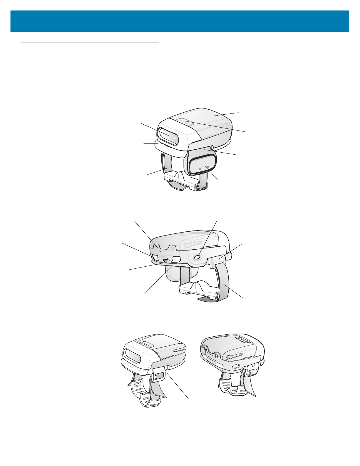
Cordless Configuration Features
Figure 1 RS507 Cordless Configuration Features
Triggered Configuration
Imager Window
Comfort Pad
Finger Strap
Battery
Battery Release Latch
Trigger Swivel Assembly
Scan Trigger
Asset Control Label
Left Scan LED
Beeper
Right Scan LED
Restore Key
Strap Buckle
Finger Strap
Triggerless Configuration
Triggerless Strap Holder
17
Page 18
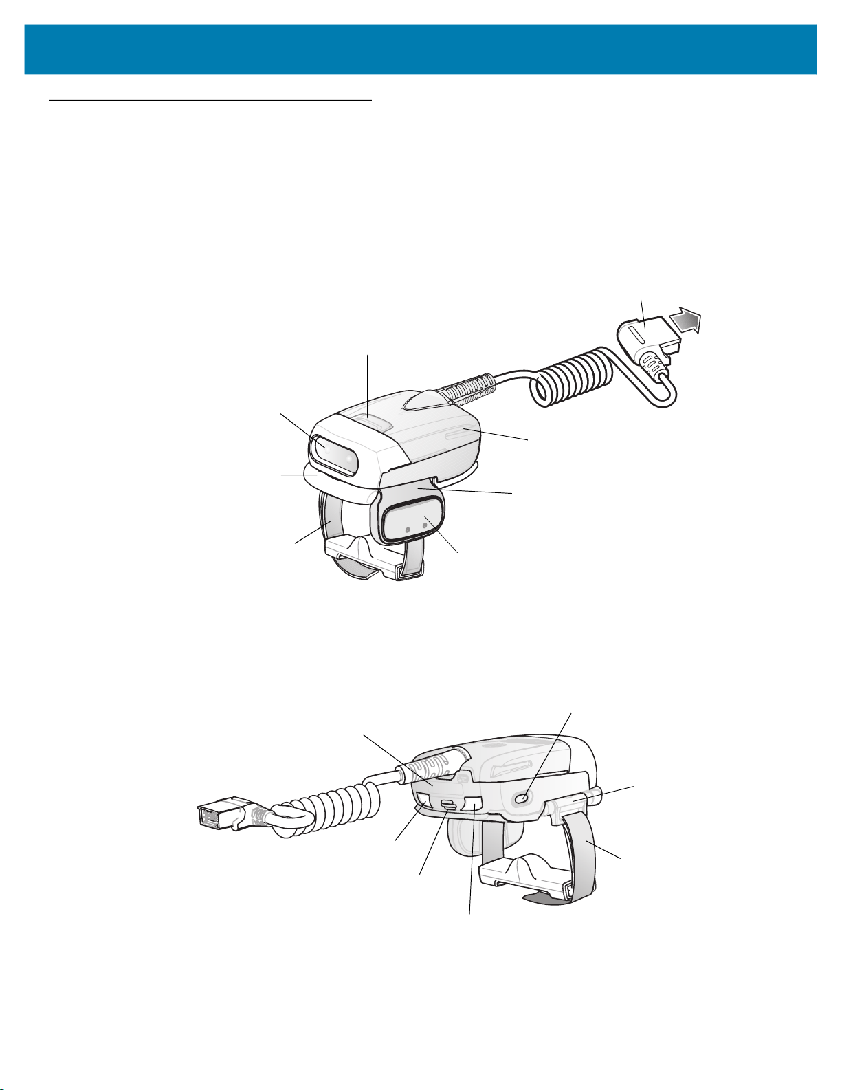
Corded Configuration Features
Figure 2 RS507 Corded Configuration Features
Release Latch
Imager Window
Getting Started
Interface Cable Connector to WT4XXX
Corded Adapter
Comfort Pad
Finger Strap
Asset Control Label
Left Scan LED
Trigger Swivel Assembly
Scan Trigger
Restore Key
Strap Buckle
Finger Strap
Beeper
Right Scan LED
18
Page 19
Getting Started
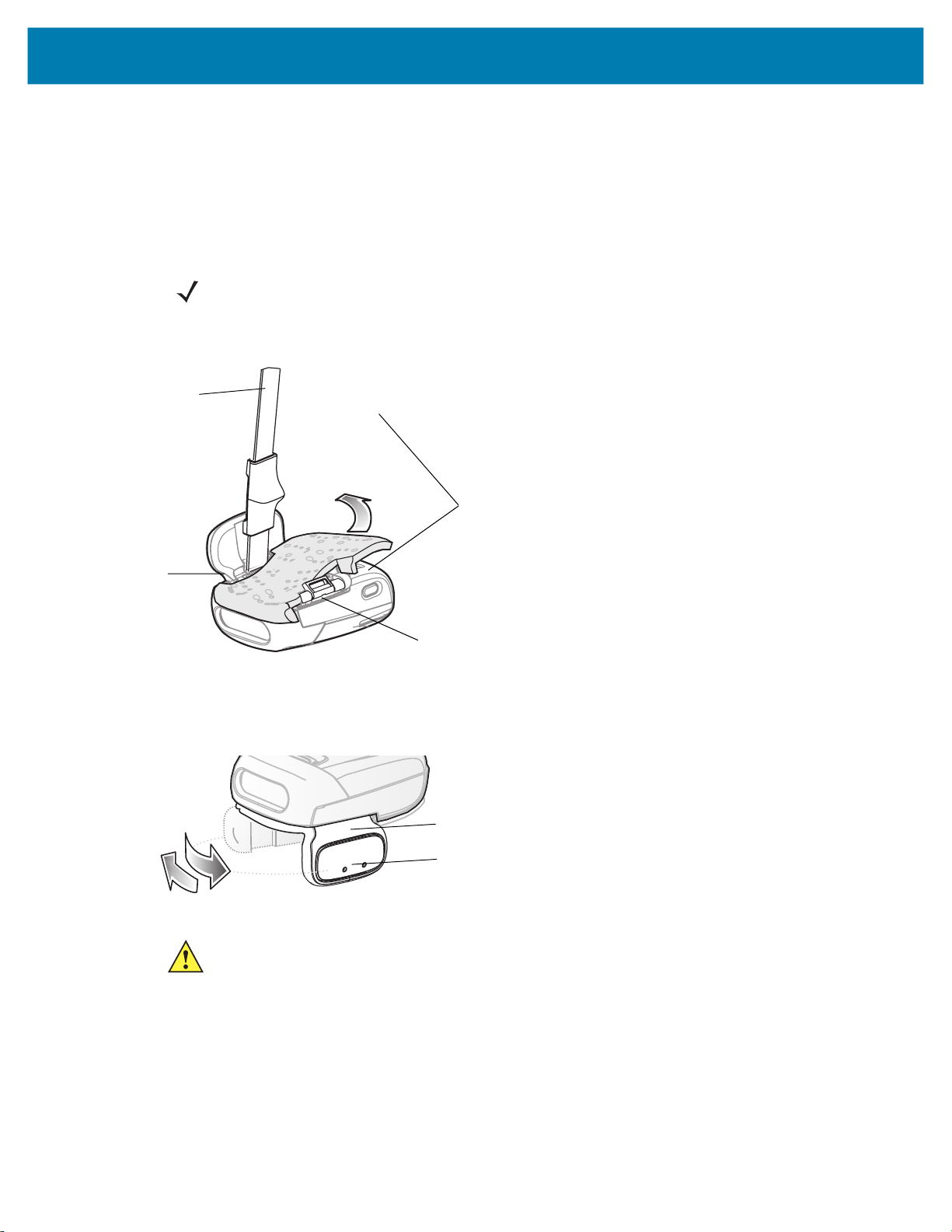
Trigger Swivel Assembly - Change Trigger Position
The Imager is worn on the index and middle fingers, and triggered with the thumb. The Trigger Swivel Assembly of
the Imager rotates to provide left-hand or right-hand use.
To change the position of the Trigger:
1. From the bottom of Imager, hold and pull the Comfort Pad off the Imager.
NOTE: When removing the Comfort Pad off the Imager, It is not necessary to remove the Finger Strap
from the Trigger Swivel Assembly.
Figure 3 Change Trigger Position - Release Finger Strap from Buckle and Remove Comfort Pad
Finger Strap
Comfort Pad
Trigger
Swivel
Assembly
Strap Buckle
2. Determine whether the Imager is used on the right or left hand and rotate the Trigger Swivel Assembly.
Figure 4 Change Trigger Swivel Assembly Position
Trigger Swivel Assembly
Scan Trigger
CAUTION:The Trigger Swivel Assembly only rotates 180° around the front of the scan assembly. Do not
rotate the Trigger Swivel Assembly past the designed stops.
3. Rotate the Trigger Swivel Assembly so that the Scan Trigger is positioned next to the thumb when the Imager
is placed on the index and middle fingers.
4. Position the Comfort Pad onto the Imager.
5. Press the Comfort Pad onto the Imager. When properly installed, the Comfort Pad locks into place.
6. Insert the Finger Strap into the Strap Buckle.
19
Page 20

Getting Started
Getting Started - Cordless Configuration
Charge the Battery
Before using the Imager, charge the battery. The SAC5070 8-Bay Battery Charger supports both standard and
extended capacity batteries.
To charge the Imager battery, refer to the SAC5070 8-Bay Battery Charger Quick Reference Guide, p/n
72-115989-01 available at: www.zebra.com/support and search for 'SAC5070'.
Install the Battery
1. Align the battery on top of the Imager.
2. Push the battery all the way into the Locking Slots of the Imager.
3. Firmly press the battery into the Imager until a “click” is heard ensuring the Battery Release Latch is fully
engaged with the Imager.
Figure 5 Install the Battery
Battery Release Latch
Battery
Locking Slots
Remove the Battery
1. Hold the Imager in one hand.
2. Press the Battery Release Latch.
3. Pull up the battery to release it from the Locking Slots of the Imager.
Wearing the Imager
1. Slide the Imager onto the index and middle fingers with the Scan Trigger next to the thumb.
20
Page 21
Getting Started
aaaaaaaaaaaaaaa
aaaaaaaaaaaaaaa
aaaaaaaaaaaaaaa
aaaaaaaaaaaaaaa
aaaaaaaaaaaaaaa
aaaaaaaaaaaaaaa
aaaaaaaaaaaaaaa
aaaaaaaaaaaaaaa
aaaaaaaaaaaaaaa
aaaaaaaaaaaaaaa
aaaaaaaaaaaaaaa
aaaaaaaaaaaaaaa
aaaaaaaaaaaaaaa
aaaaaaaaaaaaaaa
aaaaaaaaaaaaaaa
aaaaaaaaaaaaaaa
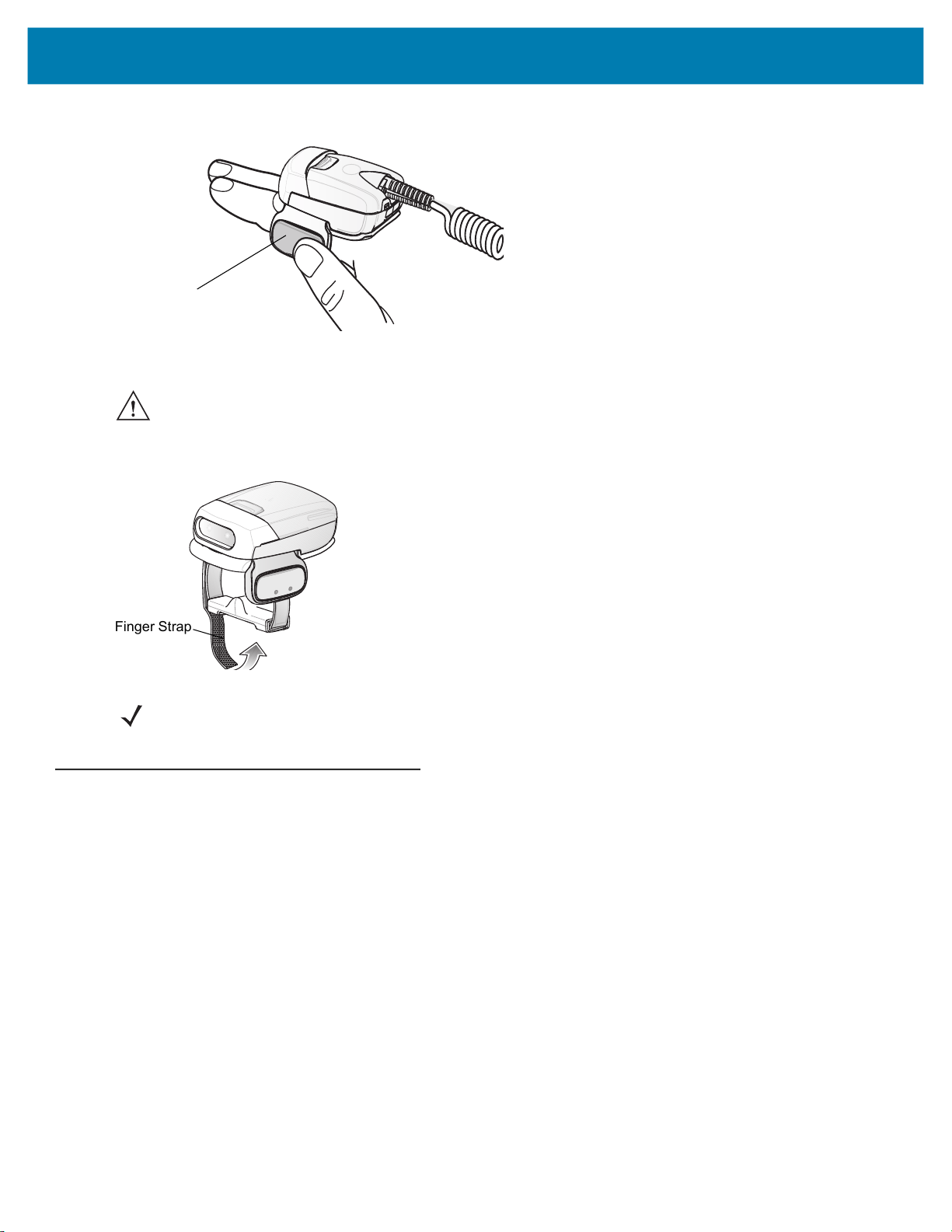
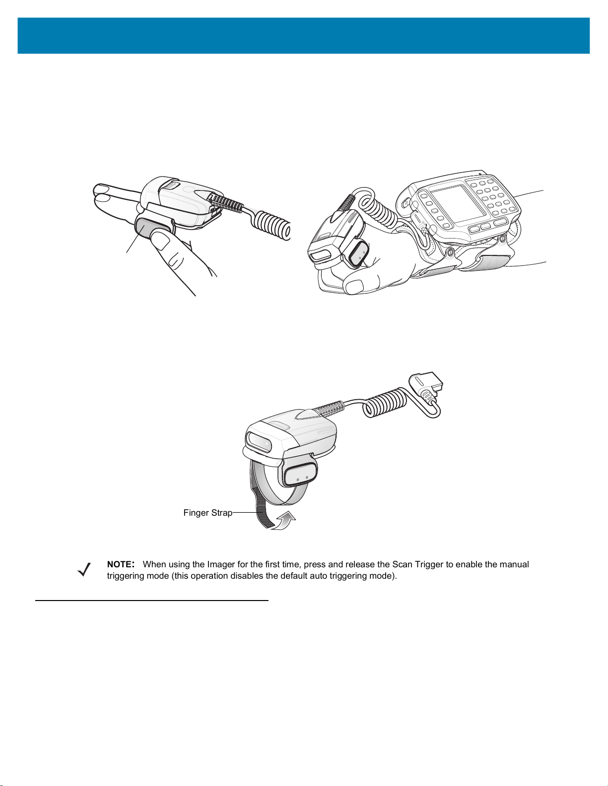
Figure 6 Wearing the Imager - Corded Configuration
Scan Trigger
2. Tighten the Finger Strap until it is snug, but not too tight.
CAUTION:To prevent user discomfort, wear the imager snug against the base of the index and middle finger. Do
not over tighten.
Figure 7 Wearing the Imager - Cordless Configuration
Finger Strap
NOTE: When using the Imager for the first time, press and release the Scan Trigger to enable the manual
triggering mode (this operation disables the default auto triggering mode).
Getting Started - Corded Configuration
In order to start using the Imager you must install the Corded Adapter.
Connect the Corded Adapter
To connect the Corded Adapter:
1. Align the Corded Adapter on top of the Imager.
2. Support the bottom side of the Imager and push the Corded Adapter all the way into the Locking Slots of the
Imager.
3. Firmly press the Corded Adapter into the Imager until a click is heard ensuring the Adapter Release Latch is
fully engaged with the Imager.
21
Page 22
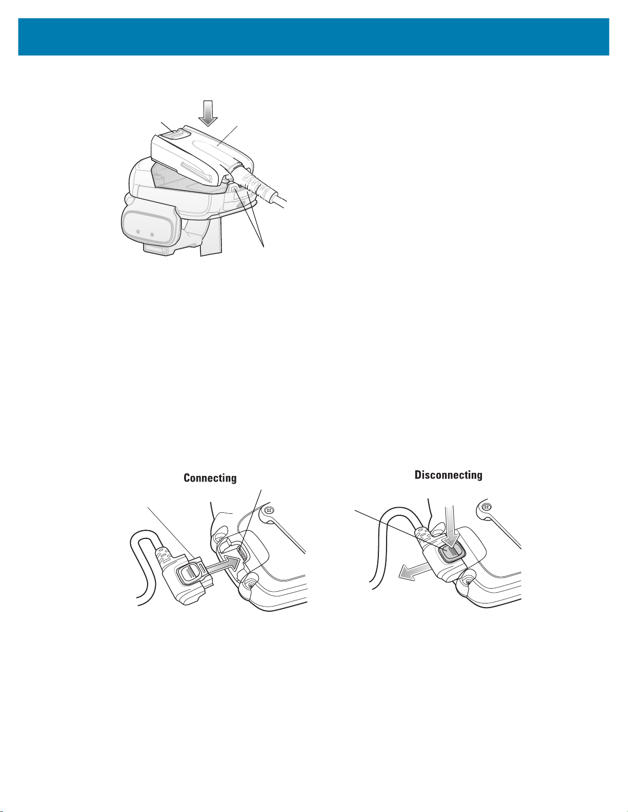
Figure 8 Connect Corded Adapter
Getting Started
Adapter Release Latch
Corded Adapter
Locking Slots
Remove the Corded Adapter
To remove the Corded Adapter:
1. Hold the Imager in one hand.
2. Press the Adapter Release Latch.
3. Pull up the Corded Adapter to release it from the Locking Slots of the Imager.
Connect to a WT4XXX Wearable Terminal
The Imager connects to the Wearable Terminal and mounts on the fingers.
Figure 9 Connecting and Disconnecting to a Wearable Terminal
WT4XXX Interface Connector
Interface Cable Connector
Disconnect
Button
2
1
To connect the Imager to the terminal:
1. On the terminal, remove the cover from the WT4XXX Interface Connector.
2. Connect the Interface Cable Connector of the Imager to the WT4XXX Interface Connector.
To disconnect the Imager from the terminal:
1. Press the Disconnect Button on the Interface Cable Connector.
2. Pull the Interface Cable Connector out of the WT4XXX Interface Connector.
22
Page 23
Getting Started
aaaaaaaaaaaaaaaaa
aaaaaaaaaaaaaaaaa
aaaaaaaaaaaaaaaaa
aaaaaaaaaaaaaaaaa
aaaaaaaaaaaaaaaaa
aaaaaaaaaaaaaaaaa
aaaaaaaaaaaaaaaaa
aaaaaaaaaaaaaaaaa
aaaaaaaaaaaaaaaaa
aaaaaaaaaaaaaaaaa
aaaaaaaaaaaaaaaaa
aaaaaaaaaaaaaaaaa
aaaaaaaaaaaaaaaaa
aaaaaaaaaaaaaaaaa
aaaaaaaaaaaaaaaaa
aaaaaaaaaaaaaaaaa
4t×Q
Wearing the Imager
To wear the Imager:
1. Slide the Imager onto the index and middle fingers with the Scan Trigger next to the thumb (see Figure 10).
Figure 10 Wear the Imager - Corded Adapter
Scan Trigger
2. Tighten the Finger Strap.
Figure 11 Wear the Corded Adapter Imager - Finger Strap
NOTE: When using the Imager for the first time, press and release the Scan Trigger to enable the manual
triggering mode (this operation disables the default auto triggering mode).
Status Indications
Finger Strap
The Imager has two Scan LEDs that provide identical indications. The Imager is also equipped with a beeper that
issues different beep sequences and patterns to indicate status.
23
Page 24

Getting Started
Table 2 defines the LED and beep sequences indications that occur during normal operation and bar code
scanning.
Table 2 Status Indications
No. LED Beep Indication Description
1. None High/low Bluetooth communication is disconnected
.
due to:
• host device is powered off.
• host device Bluetooth is off.
• Bluetooth un-pair bar code
scanned by the RS507.
• Bluetooth Disconnect bar code
scanned by the RS507.
• RS507 is out of Bluetooth range
with the host device.
2. Short green flashes None Attempting to connect over Bluetooth.
3. None Low/high Imager is connected over Bluetooth.
4. None High/low/high/low Properly decoded scan of Bluetooth
pairing bar code.
5. None Long low/ long high/ Bluetooth connection attempt failed.
If there is no acknowledgment from the
host device.
Example: Bluetooth on the host device is
off.
6. None Long low/ long high/ Long low/
long high/
7. One green flash High Proper scanning indication.
8. None 4 long beeps No Bluetooth communication after
9. Red flash 2 short beeps every 15 seconds Low battery.
10. Long red flash
followed by a green
flash
High/low High/low Clean Boot was performed successfully.
Bluetooth connection attempt is rejected.
When the RS507 tries to connect to the
host and the host rejects the connection.
Example: There is already a successful
Bluetooth connection in the host device
and it unable to create a new connection.
re-connection failure.
NOTE: When the Imager is connected by corded configuration, only “Proper scanning indication” and “Clean
Boot was perform successfully” status events are indicated.
24
Page 25

Imager Standby Mode
To save battery power, the Imager goes into Standby when not active.
The Image resumes functionality when:
• Bluetooth data is received from the mobile computer (in cordless configuration)
• Scan trigger is pressed
• Restore key is pressed
• Motion is detected (in cordless configuration)
• Incoming data from mobile computer is sensed (in corded configuration).
Bluetooth Connection
Establish Bluetooth Connection
To establish Bluetooth connection with a mobile computer:
Getting Started
1. Ensure that the Imager is within a range of 10 meters (30 feet) from the mobile computer.
2. Install the battery in the Imager.
3. Launch the Bluetooth Device (BD) address application (see Figure 12) from the mobile computer. Most BD
Address applications display a pairing bar code image on the screen of the mobile computer.
NOTE: To find the BD address application tap the Start button and select Programs > Display_BD_Address or Start
> Programs > BT Information and then tap the Generate Local BD Address Barcode button to display the BD
address bar code.
25
Page 26

Getting Started
Figure 12 Icon of Bluetooth Device (BD) Address Application
Bluetooth Device (BD) address icon
on WT4XXXApplication screen
Bluetooth Device (BD) address icon
on MC909X Demo screen
Bluetooth pairing application for
WT6000
4. Scan the pairing bar code on the mobile computer screen (see Figure 13) or a provided pairing label. When
Bluetooth Device (BD) address icon on
Windows Mobile Programs screen
BTUI pairing application for WT41N0
scanning, the Imager emits one string of high/low/high/low beeps.
NOTE: To create printed pairing bar code label, refer to Pairing Bar Code Format on page 28.
Figure 13 Pairing Bar Code Example as Shown on the Mobile Computer Screen
26
Page 27

Getting Started
5. The Scan LED starts flashing green indicating that the Imager is attempting to establish connection with a
mobile computer.
NOTE: If the Imager default PIN code is required for establishing connection, enter the following code: "12345".
You may also need to set the authentication and encryption to Enabled.
6. When connection is established, the Scan LED turns off and the Imager emits one string of low/high beeps.
The Imager is connected and ready for scanning.
NOTE: When replacing the Imager battery, the Imager memory retains the pairing information of the last paired
mobile computer.
Restore Lost Bluetooth Connection
The Imager maintains Bluetooth communication with a mobile computer within a range of 10 meters (30 feet).
When the Imager fails to establish connection or connection is lost during operation, the Imager emits one string of
high/low beeps.
To reestablish the Bluetooth connection with a mobile computer:
1. Ensure that the Imager is within a range of 10 meters (30 feet) from the mobile computer.
2. Ensure that the mobile computer is on and “awake” (not in Suspend mode).
3. The Imager automatically attempts reconnecting to the mobile computer for 30 seconds (Scan LED flashes
green). If automatic re-connection fails, verify that the Imager is within Bluetooth range and briefly press the
Restore Key on the Imager to reconnect.
NOTE: You can also reconnect by scanning a pairing bar code from the mobile computer screen or provided
label. When scanning, the Imager emits one string of high/low/high/low beeps.
4. The Scan LED starts flashing green indicating that the Imager is attempting to establish connection with a
mobile computer. The Scan LED turns off and the Imager emits one string of low/high beeps indicating that the
Imager is connected and ready for scanning.
Remove Bluetooth Connection
Remove Bluetooth connection to allow the Imager to connect to another mobile computer or to enable the a mobile
computer to accept the connection from another Imager.
NOTE: Removing Bluetooth connection is only required if the Imager is configured to auto-connect upon
power-up (permanent pairing is enabled) and has to be paired with a different mobile computer.
To remove Bluetooth connection:
1. Scan an un-pairing bar code for disconnecting the Imager from the mobile computer.
Figure 14 Un-pairing Bar Code
2. The Imager emits one string of high/low beeps indicating that Bluetooth communication with the mobile
computer is disconnected.
27
Page 28

Getting Started
Pairing Bar Code Format
In order to pair the Imager with a mobile computer over Bluetooth, a pairing bar code must be created. You can use
the Display_BD_Address application on the mobile computer, or create and print a pairing bar code label. To
create a pairing bar code label, the Bluetooth address of the mobile computer should be available (refer to the
mobile computer user guide).
Pairing bar codes are Code 128, Data Matrix or Aztec symbologies formatted as follows:
<Fnc3>Bxxxxxxxxxxxx
Where xxxxxxxxxxxx represents the 12-character Bluetooth address.
Pairing Bar Code Example
If the mobile computer to which the Imager connects has a Bluetooth address of 11:22:33:44:55:66, then the
pairing bar code is:
Figure 15 Creating a Pairing Bluetooth Bar Code
Paring Bar Code Content: <Fnc 3> ‘B’ + Bluetooth Address
Scan
The Imager uses digital camera technology to take an image of a bar code and software decoding algorithms are
executed to extract the bar code data from the image.
Scan Triggering Modes
Manual Triggering (Triggered models only)
1. Launch a scanning software application on the mobile computer.
2. Position the Imager approximately 22.8 cm (9 inches) from a bar code and press the Scan Trigger. Position the
cross hair laser beam to cover the bar code. The Imager takes a digital picture (image) of the bar code and
stores it in memory for decoding.
NOTE: After battery is inserted or a corded adaptor is connected (on both sides), the first trigger press disables the
auto triggering mode.
3. One green flash of the LEDs is given and a high beep sounds to indicate that the bar code was properly
decoded.
NOTE: In some configurations proper decoding of a bar code is indicated by the software application running on
the mobile computer.
Auto-triggering (Triggerless models only)
The Imager is provided with auto-triggering capability. In auto-triggering mode, both motion and proximity sensors
are used to trigger the Imager when the user intends to scan a bar code.
28
Page 29
Getting Started
With auto-triggering activated, the Imager automatically scans when motion stops and a bar code is placed within
the depth of field of the Imager. The Imager scans the bar code and turns off to conserve power.
To scan a bar code in auto-triggering mode:
1. Position the Imager approximately 22.8 cm (9 inches) from a bar code.
2. Aim at the bar code.
3. The Imager takes a picture (image) of the bar code and stores it in memory for decoding.
4. One green flash of the Scan LEDs and a high beep indicates that a bar code was properly decoded.
NOTE: In some applications, proper detection of a bar code is indicated by a software application running on
the mobile computer.
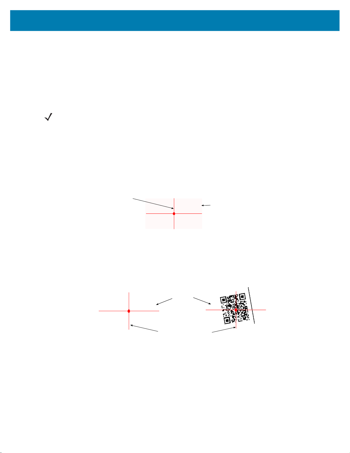
Aiming the Imager
The aiming pattern of the Imager is a cross hair laser beam with bright center dot (see Figure 16). The virtual
rectangle made by the cross hair reflects the field of view of the Imager. The aiming pattern is used to position the
bar code within the field of view.
Figure 16 Cross Hair Laser Beam
Cross hair laser beam
Virtual rectangle made by the cross hair laser beam
Enter the symbol in any orientation within the virtual rectangle made by the cross hair laser beam, making use of its
omnidirectional reading capability within the entire field of view.
Figure 17 Symbol Scan Orientation
1D Bar Code
Symbol
2D Bar Code
@1234@
Aiming pattern Pattern
The Imager can also read a bar code presented within the aiming pattern but not centered (see the top bar codes
on Figure 18). The bar codes marked with X in Figure 18, however, show bar code aiming that may result in no
decode.
When using the application on your mobile computer in “Pick List” mode, the Bright Center Dot can be positioned
anywhere on the symbol (see Figure 16).The top examples in Figure 18 show acceptable aiming options, while the
bottom examples can not be decoded.
29
Page 30

Getting Started
012345
012345
012345
012345
Figure 18 Acceptable Aiming Options
The aiming pattern is smaller when the Imager is closer to the symbol and larger when it is farther from the symbol.
Scan symbols with smaller bars or elements (mil size) closer to the Imager and those with larger bars or elements
(mil size) farther from the Imager.
1. Hold the Imager between two and eleven inches from the bar code (depending on the bar code density).
NOTE: When a symbol is under transparent plastic or on a mobile computer screen, it is recommended to use a
tilt (pitch) or skew scan angle to minimize reflection.
2. Press the Scan trigger. The aiming pattern illuminates red indicating that the laser is on. One green flash of the
Scan LED and a high beep indicates that a bar code was properly decoded.
Customize the Imager
Changing from Triggered to Triggerless Configuration
To change from Triggered to Triggerless configuration:
1. Remove the Comfort Pad (see Comfort Pad Replacement on page 40).
2. Remove the Trigger Swivel Assembly (see Trigger Swivel Assembly Replacement on page 41).
3. Install the Triggerless Strap Holder (see Triggerless Strap Holder Replacement on page 42).
4. Install the Comfort Pad (see Comfort Pad Replacement on page 40).
5. Perform a cold boot (see Cold Boot on page 31).
Changing Triggerless to Triggered Configuration
To change from Triggerless to Triggered configuration:
1. Remove the Comfort Pad (see Comfort Pad Replacement on page 40).
2. Remove the Triggerless Strap Holder (see Triggerless Strap Holder Replacement on page 42).
3. Install the Trigger Swivel Assembly (see Trigger Swivel Assembly Replacement on page 41).
4. Install the Comfort Pad (see Comfort Pad Replacement on page 40).
5. Perform a cold boot (see Cold Boot on page 31).
30
Page 31

6. Press and release the Scan Trigger to enable the manual triggering mode (this operation disables the default
Triggerless mode).
Resetting the Imager
If the Imager stops responding to input, reset it. There are three reset functions, warm boot, cold boot and clean
boot. Perform a warm boot first. If the Imager still does not respond, perform a cold boot. Perform clean boot to
restore the Imager to its factory default configuration.
Warm Boot
To perform warm boot, press and hold the Restore Key for more than six seconds.
Cold Boot
Cold boot restores the Imager’s operation by resetting its software. To perform cold boot, remove and re-insert the
battery into the Imager. When using a corded Imager model with WT4XXX, remove and reconnect the interface
cable that connects between the Imager and the WT4XXX.
Getting Started
Clean Boot
Clean Boot restores the Imager to its factory default configuration.
To perform clean boot:
1. Remove battery or disconnect the Corded Adapter.
2. Press and hold the Restore Key.
3. Insert the battery or Corded Adapter into the Imager.
4. Continue to press and hold the Restore Key for about five seconds until a chirp is heard and the Scan LEDs
flash green. The Imager is now in its factory default configuration.
NOTE: The factory default configuration is set in the factory or the service center. These parameters are unique
for each Imager and cannot be changed. The Factory default configuration includes: Imager serial number,
Bluetooth Device (BD) address, model number, production date and proximity calibration.
31
Page 32

SAC5070 8-Bay Battery Charger
Introduction
The SAC5070 8-Bay Battery Charger is an accessory for the RS507/RS507X Hands-free Imager and provides a
quick way to recharge the Lithium-ion battery that provide power for the RS507/RS507X Hands-Free Imager. One
charger can hold up to eight batteries at a time.
The 8-Bay Battery Charger supports both standard and extended capacity batteries. The Charger may only be
used indoors.
Unpacking the Charger
After opening the shipping box, inspect the contents. You should have received the following:
Model Description
SAC5070-800CR USA model x x x x
SAC5070-801CR International model x x * x
* For AC line cord, contact the Zebra representative in your country.
Inspect the equipment for damage. If you are missing any equipment or if you find any damaged equipment,
contact Zebra Support immediately.
8-Bay Battery
Charger
Power supply
AC Line
Cord
Quick Start
Guide
32
Page 33

Parts of the Charger
Figure 19 Parts of the Charger
Charger Front
SAC5070 8-Bay Battery Charger
RS507 Imager Rest Compartment
Charger Back
Charging Bay
Asset Control Label
M4 Screw Inserts (X4)
(Screws not Included)
Batteries Age Test Button
Charge Status LED
Wall Mount Hole (X4)
Power Supply Cable Duct
M4 Screw Inserts (X4)
(Screws not Included)
Power Supply Connector
Power Supply Cable Duct
Service Port Door
(Do not open - for service use only)
33
Page 34

Installation
Tabletop / Shelf Set Up
To set the Charger on a tabletop or shelf:
1. Place the Charger and the Power Supply Unit on a tabletop or shelf.
NOTE: When required, use the screw inserts at the back and base to secure the Charger to the tabletop or shelf
surface.
2. Connect the Power Supply Cable to the power connector on the back of the Charger.
3. Use the Power Supply Cable Duct, on the back of the Charger, to route the Power Supply Cable to the left or
right side of the Charger.
4. Connect the AC plug of the AC Power Cord to a standard electrical outlet.
Figure 20 Charger Installation
SAC5070 8-Bay Battery Charger
Wall Mount
100-240 VAC, 50-60 Hz Outlet
Power Supply Cable Duct
AC Power Cord
Power Supply Cable
Power Supply Unit
WARNING: For safe mounting, it is essential to use wall anchors appropriate to the wall type (i.e. plaster, drywall,
concrete, etc.). Mount to wood studs whenever possible.
To mount the Charger on a wall:
1. Mark the screw location on the wall.
34
Page 35

SAC5070 8-Bay Battery Charger
2. Use four screws to mount the Charger to a wall. Be sure to use additional wall mounting hardware, as needed,
for safe mounting according to the wall type.
3. Connect the power supply cable to the power connector on the back of the Charger (see Figure 21).
4. Use the Power Supply Cable Duct, on the back of the Charger, to route the Power Supply Cable to the left or
right side of the Charger.
5. Place the Power Supply Unit on a shelf or tabletop.
6. Connect the AC plug of the AC Power Cord to a standard electrical outlet.
Figure 21 Wall Mounting of Charger
5 mm
220 mm (8.6 inches)
(0.19 inches)
38 mm (1.5 inches)
Inserting the Imager Battery in the Charger
The Charger supports both standard and extended capacity batteries.
10 mm
(0.39 inches)
35
Page 36

SAC5070 8-Bay Battery Charger
Figure 22 Inserting the Imager Battery into the Charger
Charger Bay
Standard Battery
Charge the Battery
CAUTION:Only Lithium-ion batteries that have been designed for use with the RS507 Hands-free Imager can be
recharged by the Charger. Do not attempt to recharge other types of rechargeable batteries or any
type of batteries. Doing so could destroy those batteries and damage the Charger.
NOTE: Batteries should be charged within the 0°C (+32°F) and +40°C (+104°F) ambient temperature range.
To charge the battery(s):
1. Insert the battery(s) into the 8-Bay Battery Charger so that the contacts of the battery are first to enter, facing
down, gently. Do not use excessive force.
2. The 8-Bay Battery Charger starts to charge automatically. On each bay, the flashing amber Charge Status
LED (see Figure 19) indicates the charge status.
A full charge of a depleted battery takes up to four hours. The Charge Status LED lights solid amber when the
battery is fully charged.
Battery Age Test
The battery age test checks the battery capacity when fully charged. A worn-out battery is considered to have less
than 80% of its nominal capacity. The battery test is simultaneously performed for all batteries inserted into the
charger. It is recommended to perform battery age testing once a month. The age test may take up to 16 hours.
NOTE: A battery removed during test and re-inserted is excluded from the test but continues normal charging.
36
Page 37

SAC5070 8-Bay Battery Charger
To test the battery(s):
1. Insert one or more batteries into Charging Bay(s).
2. Press and hold the Test Button for approximately 3 seconds until the Charge Status LED of each active bay
flashes green.
3. Refer to the table below when the indication of the Charge Status LED changes.
Charge Status LED
The Charge Status LEDs show the charge status of each Charging Bay:
Table 3 Charge LED - Status Indications
LED Indication Status
Flashing amber Charging in progress.
Solid amber Charging is completed.
Flashing green Battery age testing in progress.
Flashing red/green Defective battery or error in charging; re-insert the battery into the bay.
Solid green Battery age test and charge are completed. Battery is good.
Solid red Battery age test and charge are completed. Battery capacity is marginal.
Flashing red Battery age test and charge are completed. Battery is worn out.
37
Page 38

Troubleshooting & Maintenance
Introduction
This chapter provides suggested Imager and Charger troubleshooting and maintenance.
Troubleshooting
Imager
Table 4 Imager Troubleshooting
Problem Cause Solution
Laser aiming pattern
does not display when
pressing the Scan
Trigger.
Corded: Interface cable is not secure. Verify that the interface cable is properly
connected.
Cordless: Battery is not charged. Replace or charge battery.
Power is not applied to Imager. Corded: Verify that the mobile computer
has a fully charged battery installed.
Cordless: Replace or charge Imager
battery.
Scan application on the mobile
computer is not functioning.
Imager does not respond. Reset the Imager (See Resetting the
Restart the scanning application on the
mobile computer.
Imager on page 31).
38
Page 39

Table 4 Imager Troubleshooting
Problem Cause Solution
Troubleshooting & Maintenance
Imager does not decode
a bar code.
NOTE: If after performing these checks the Imager still experiences problems, contact the distributor or call
Zebra Support. See Service Information on page 14.
Bar code is unreadable. Verify that the bar code is not defective,
i.e., smudged or damaged.
Exit window is dirty. Clean exit window with a lens tissue.
Tissues for eyeglasses work well. Do not
use tissues coated with lotion (see
Cleaning the Imager on page 46).
Bar code symbology is not supported
or enabled.
Cordless:
disconnected.
Bluetooth link is
See your system administrator.
Reestablish Bluetooth connection (See
Establish Bluetooth Connection on page
25).
Charger
Table 5 Charger Troubleshooting
Problem Solution
The Power LED does not light Make sure the Power plug of the Power Supply Unit is plugged into a wall
outlet and the connector on the end of the Power Supply Cable is
plugged into the Charger’s power connector.
The battery takes too long to
recharge
LED indication continuously
changes from red to green
Plug the Power plug of the Power Supply Unit into another outlet.
Replace the Power Supply Unit.
Contact a service representative (see Service Information on page 14).
Ensure that room/battery temperatures are within charging range
0 ºC to +40 ºC (+32 ºF to +104 ºF).
Clean the contacts on the battery (see Cleaning the Charger on page 47).
Try another battery to make sure the Charger functions properly. (If the
charge time is more than four hours the Charge Status LED flashes
red/green.)
Contact a service representative (see Service Information on page 14).
Remove and re-insert the battery into the charging bay.
Check for dirt on battery charging contacts and/or charging bay contacts
(see Cleaning the Charger on page 47).
Replace battery with a new one.
Contact a service representative (see Service Information on page 14).
39
Page 40

Maintenance
Cleaning the scan window is the basic maintenance required. A dirty window can affect scanning accuracy.
• Do not allow abrasive material to touch the window.
• Remove any dirt particles with a damp cloth.
• Wipe the window using a tissue moistened with ammonia/water.
• Do not spray water or other cleaning liquids directly into the window.
Maintaining the Imager
Comfort Pad Replacement
Removal
To remove the Comfort Pad:
1. Flip the Imager over, such that the bottom of the Imager and the Comfort Pad are facing upwards.
2. On a Triggerless Swivel Assembly, remove the M2 screw.
3. Insert the tip of your finger under the edge of the Comfort Pad at the back of the Imager.
4. Lift the Comfort Pad upwards and remove it from the Imager.
Troubleshooting & Maintenance
CAUTION:Removing the Comfort Pad other than the described above may result in damage to the Trigger
Swivel Assembly of the Imager.
NOTE: It is not necessary to remove the Finger Strap from the Trigger Swivel Assembly.
Figure 23 Removal of Comfort Pad
Trigger Swivel Assembly
Triggerless Strap Holder
40
Page 41

Troubleshooting & Maintenance
Installation
NOTE: Only use a Trigger Comfort Pad on a Trigger Swivel Assembly. To install the Triggerless Comfort Pad
on a Trigger Swivel Assembly, do not use the M2 screw.
To install the Comfort Pad:
1. Position the Comfort Pad onto the Imager as shown.
Figure 24 Installation of Comfort Pad
2. Press the Comfort Pad onto the Imager. When properly installed, the Comfort Pad locks into place.
3. On a Triggerless Swivel Assembly, install the M2 screw.
Trigger Swivel Assembly Replacement
Removal
To remove the Trigger Swivel Assembly:
1. Turn the Imager upside-down.
2. Remove the Comfort Pad.
3. Use a paper clip or similar object to press the Release Latch.
Figure 25 Removal of Trigger Swivel Assembly
3
2
Imager Back
Release Latch
4. Rotate the Trigger Swivel Assembly to align with the back of the Imager.
5. Lift the Trigger Swivel Assembly off the scan assembly.
1
41
Page 42

Troubleshooting & Maintenance
Installation
To install the Trigger Swivel Assembly:
1. Turn the Imager upside-down.
2. Position the Trigger Swivel Assembly to align with the back of the Imager.
3. Lower the Trigger Swivel Assembly onto the scan assembly.
Figure 26 Installation of Trigger Swivel Assembly
2
Trigger Swivel Assembly
1
1. Rotate the Trigger Swivel Assembly 1/4 turn counterclockwise.
2. Press the Comfort Pad onto the Imager. When properly installed, the Comfort Pad locks into place.
Triggerless Strap Holder Replacement
NOTE: The Triggerless Strap Holder should be installed when the Imager is intended to be used in Motion and
Proximity Initiated bar code read mode.
Removal
To remove the Triggerless Strap Holder:
1. Turn the Imager upside-down.
2. Remove the Comfort Pad.
3. Use a paper clip or similar object to press the Release Latch.
42
Page 43

Troubleshooting & Maintenance
Figure 27 Removal of Triggerless Strap Holder
3
2
Release Latch
4. Rotate the Triggerless Strap Holder to align with the back of the Imager.
5. Lift the Triggerless Strap Holder off the Imager.
Imager Back
Triggerless Strap Holder
1
Installation
To install the Triggerless Strap Holder:
1. Turn the Imager upside-down.
2. Position the Triggerless Strap Holder to align with the back of the Imager.
Figure 28 Installation of Triggerless Strap Holder
2
1
3. Lower the Triggerless Strap Holder onto the Imager.
4. Rotate Triggerless Strap Holder 1/4 turn counterclockwise.
Finger Strap Replacement (Trigger Swivel Assembly)
Removal
1. Remove the Finger Strap from the Strap Buckle.
2. Pull the Finger Strap out of the Trigger Swivel Assembly.
43
Page 44
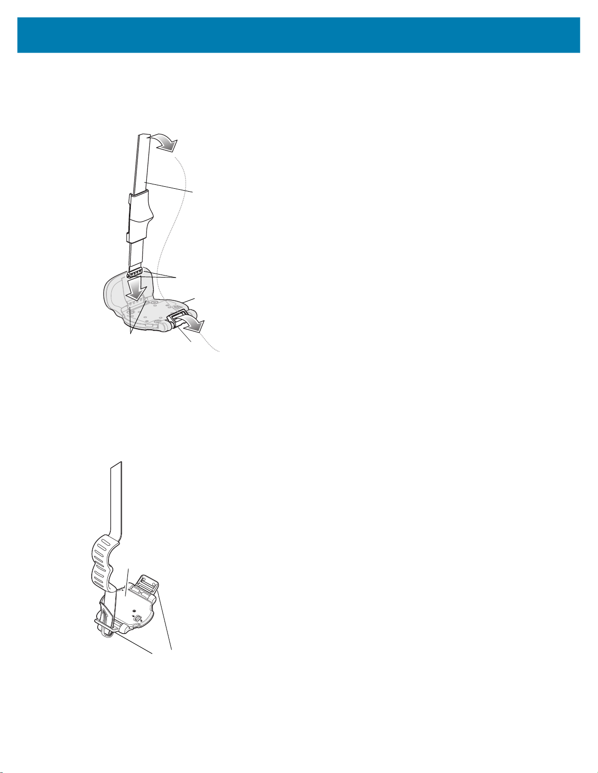
Troubleshooting & Maintenance
Installation
1. Align a new Finger Strap with the Slots in the Trigger Swivel Assembly.
Figure 29 Finger Strap Replacement (Trigger Swivel Assembly)
Finger Strap
Strap Pins
Trigger Swivel Assembly
Slots
2. Gently press the Strap Pins to engage with the Slots of the Trigger Swivel Assembly. The Strap Pins snap into
the slots.
3. Slip the Finger Strap through the Strap Buckle.
Strap Buckle
Finger Strap Replacement (Triggerless Strap Holder)
Figure 30 Replacement of Finger Strap (Triggerless Strap Holder)
Triggerless Strap Holder
Strap Buckles
Removal
Remove the Finger Strap from the Strap Buckles.
44
Page 45

Troubleshooting & Maintenance
Installation
Slip the Finger Strap through the Strap Buckles.
Strap Buckle Replacement
Figure 31 Strap Buckle Replacement
Removal
1. Remove the Trigger Swivel Assembly (see Trigger Swivel Assembly Replacement on page 41).
2. Press the Strap Buckle off the Trigger Swivel Assembly Pin.
Installation
1. Align the pin slot of Strap Buckle with the pin of the Trigger Swivel Assembly.
Figure 32 Strap Buckle Replacement
Strap Buckle Pin
Strap Buckle
2. Gently press the pin slot of Strap Buckle to engage with the pin of the Trigger Swivel Assembly. The pin slot
snaps onto the pin.
3. Install the Trigger Swivel Assembly (see Trigger Swivel Assembly Replacement on page 41).
Field Replaceable Parts
Table 6 Imager Field Replaceable Parts
No Part Description
1 KT-CLMPT-RS507-01R Trigger Swivel Assembly.
2 KT-BKL-RS507-10R Set of 10 Buckles for Hook and Loop Strap.
3 KT-BKLN-RS507-10R Set of 10 Buckles for Triggerless Elastic Finger Strap.
4 KT-BKLT-RS507-10R Set of 10 Buckles for Trigger Elastic Finger Strap.
5 KT-CLMPN-RS507-01R Triggerless Strap Holder.
6 KT-PAD-RS507-10R Set of 10 Trigger Comfort Pads.
7 KT-PAD2-RS507-10R Set of 10 Triggerless Comfort Pads. M2 Screw Included.
8 KT-STRPN-RS507-10R Set of 10 Triggerless Finger Strap.
9 KT-STRPT-RS507-10R Set of 10 Trigger Finger Strap.
10 KT-STRP2-RS507-10R Set of 10 Trigger or Triggerless Elastic Strap.
11 KTBTRYRS50EAB00-01 Standard Battery.
45
Page 46
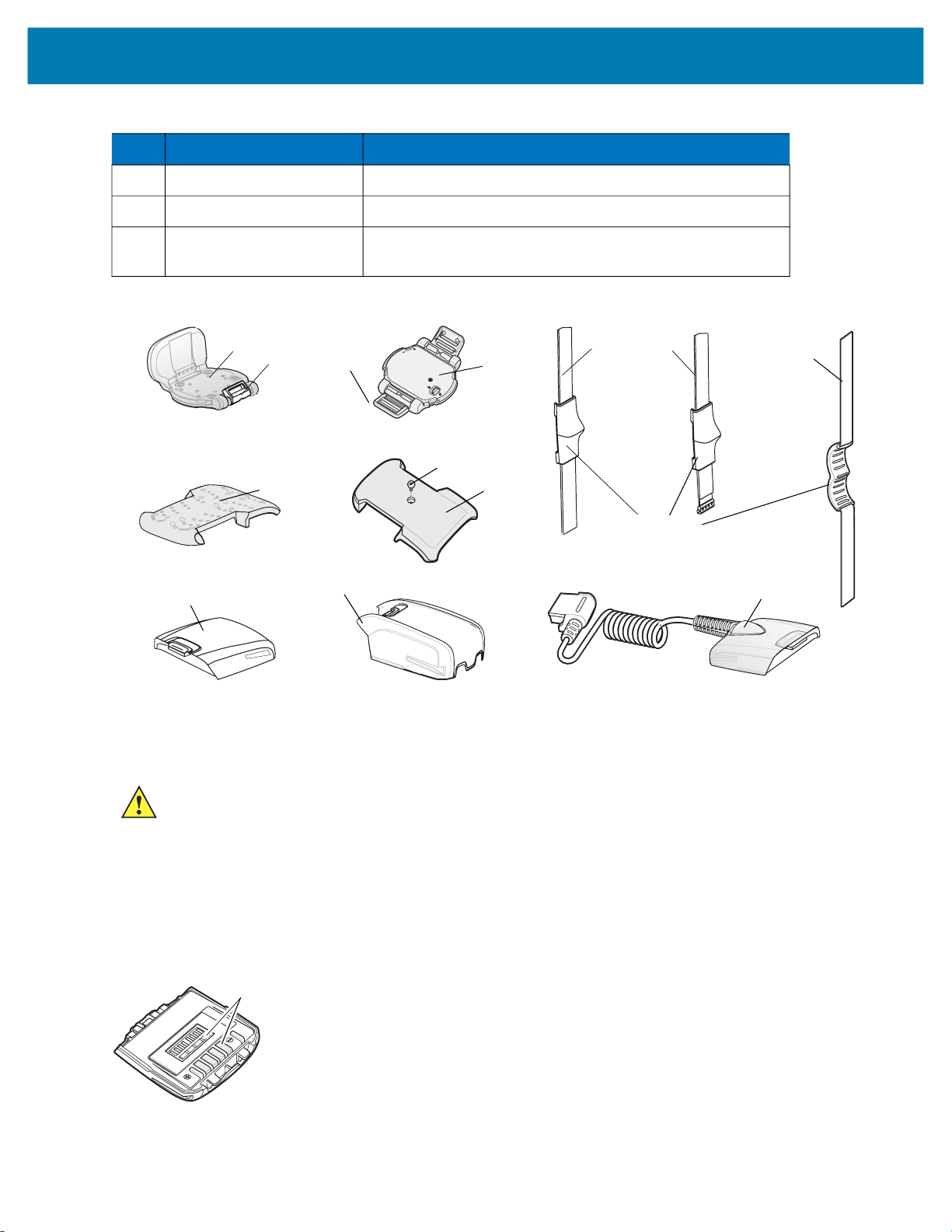
Troubleshooting & Maintenance
Table 6 Imager Field Replaceable Parts
No Part Description
12 KTBTRYRS50EAB02-01 Extended Battery.
13 ADPTRWT-RS507-04R Corded Adapter.
KT-ESTRPTRS507-10R Set of 10 Elastic Straps with Buckles for Trigger and
Triggerless configurations.
Figure 33 Imager Field Replaceable Parts
1
2
6
11
3 & 4
12
5
M2 Screw
7
8
9
Finger Support
Cleaning the Imager
Wipe the exit window periodically with a lens tissue or other material suitable for cleaning eyeglasses.
10
13
CAUTION:Do not pour, spray, or spill any liquid on the Imager.
The gold plated battery contacts do not tarnish or oxidize. No maintenance should be needed. If the contacts need
to be cleaned:
1. Wet the tip of a cotton swab with isopropyl alcohol and squeeze the excess alcohol from the swab.
2. Wipe the metal contacts with the damp swab.
Figure 34 Cleaning the Battery
Battery Contacts
Battery Contacts
46
Page 47

Troubleshooting & Maintenance
Maintaining the Charger
The Charger is well constructed and durable; however, it is a precision electronic device and must be treated as
such.
Follow the procedures in this section to ensure reliable service.
Operating conditions for the Charger
The Charger is designed to operate in environments that are normally free of dust, dirt, and moisture. It can be
operated at temperatures between 0°C (+32°F) and +40°C (+104°F).
Handling the Charger
• Do not attempt to open the Charger. No user-serviceable parts are inside.
• Charge only Lithium-ion batteries that have been designed for use with the Imager. Do not attempt to
recharge other types of rechargeable batteries or any type of primary batteries.
• Do not place objects other than Imager batteries inside the Charger.
• Protect the Charger from excessive heat, cold, moisture, and harsh, dirty environments.
• Do not leave the Charger where moisture will condense on it.
Cleaning the Charger
CAUTION:Do not pour, spray, or spill any liquid on the Charger.
The gold plated battery contacts do not tarnish or oxidize. No maintenance should be needed. If the contacts need
to be cleaned:
1. Remove power from the Charger.
2. Wet the tip of a cotton swab with isopropyl alcohol and squeeze the excess alcohol from the swab.
3. Wipe the metal contacts with the damp swab.
47
Page 48

RS507 Update and Configuration
Introduction
This chapter covers the following topics:
• Configuring the Imager
• Imager Motion and Proximity Configuration
• Debugging logger
• Firmware upgrade
Configuring the Imager
Introduction
The Imager is a modular product used in several hardware configurations. Such configurations may include corded
or cordless connection to a terminal / mobile computer with manual or automatic triggering.
The Imager is provided with a default software configuration set in the factory. This software configuration can be
optimized by the customer to meet their specific operational requirements. Therefore, before using the Imager, it is
essential that the Imager be properly configured to harness its extensive capabilities and gain maximum efficiency.
There are several ways to configure the Imager. The best way is to set the parameters for each application
allowing the required degrees of freedom. In some cases it is recommended to allow the user to select between the
various operational modes or use cases, each with its own set of parameters.
Zebra mobile computers using the EMDK may utilize the SCAN and/or RSM APIs to configure the operation of the
Imager. Zebra terminals that cannot use the EMDK, may configure some operations of the Imager by scanning
special configuration bar codes (see Miscellaneous Imager Options on page 66) as done with many of Zebra bar
code scanners.
A selection of most configured Imager parameters can be set with the Remote Scanner Management Sample
(RSMSample) application installed on all Zebra mobile computers supporting the Imager. Some of the Imager
parameters can also be set by the Control Panel application.
Once connected to a mobile computer, the application running on the mobile computer overrides the Imager
parameters previously set.
48
Page 49

RS507 Update and Configuration
Control Panel Application
The Control Panel (CTLpanel) application can be used for configuring the Imager by changing its values. The
Control Panel application also enables one to retrieve and display the current setting of each value.
The Control Panel application together with the RSMsample application enable the user to configure the RS507.
Users with Mobile computer that do not have the Control Panel application installed can download the application
(CtlPanelWM.exe) and related documentation from the Support Central site at: http://www.zebra.com/support.
The following example describes how to read and configure new values of the Imager attributes.
To set new attribute values:
1. When using the WT4XXX, from the App Launcher screen, open the Utilities folder and start the Control Panel
application. When using a mobile computer with Windows Mobile, open the Application folder and start the
CtlPanelWM application.
Figure 35 Starting the Control Panel Application
WT4XXX - Control Panel Application
2. Select Scanner Settings .....
Figure 36 Scanner Settings
Windows Mobile -
Control Panel Application
49
Page 50

RS507 Update and Configuration
3. Use the > < keys to select scanner. Select SCN1 for corded Imager or SCN2 for cordless Imager (Bluetooth).
NOTE: Before you select
4. Select Reader Params…
SCN2
make sure to pair and connect the Imager to the mobile computer.
Figure 37 Reader Params
5. Use the > < keys to change the Picklist Mode to Enable and press the OK button.
Figure 38 Picklist Mode
This setting is retained until cold boot is performed to the mobile computer or new setting is entered through
the Control Panel application.
6. Re-start your scan application and verify that Picklist Mode is enabled.
RSMSample Application
The Remote Scanner Management Sample (RSMSample) application is used for configuring the Imager by
changing its attribute values.
setting of each attribute.
download the application and related documentation from the Support Central site at: www.zebra.com/support.
NOTE: When the Imager is connected to a mobile computer, configuration by scanning bar codes is disabled. In
such case, the Imager configuration is performed by the application (e.g RSMSamplen) running on the mobile
computer. The new configuration overrides the previous configuration. The new configuration is saved in the
Imager memory after disconnecting the Imager from the mobile computer or terminating the application.
The following example describes how to read and configure new values of the Imager attributes.
The RSMSample application also enables one to retrieve and display the current
Users with mobile computer that do not have the RSMSample application installed can
50
Page 51

RS507 Update and Configuration
To set new attribute values:
1. From the mobile computer Application folder, run the RSMSample application.
Figure 39 Mobile Computer Application Folder - RSMSample Application Icon
WT4XXX - RSMSample Application
2. From the Dialog window, select Bluetooth SSI Scanner Driver.
Windows Mobile - RSMSample Application
Figure 40 Dialog Window - Bluetooth SSI Scanner Driver
3. Press the Get All Supported Attributes button to display all supported attributes.
Figure 41 RSMSample Application - Get All Supported Attributes Button
51
Page 52

RS507 Update and Configuration
4. The Attribute scroll window displays all supported attributes (see Table on page 53) and an operation success
indication.
Figure 42 RSMSample Application - Attribute Scroll Window
fh
Attribute Scroll Window
Operation Success Indication
5. Select the attribute you wish to change and press the Get button to display the current value of the attribute.
Figure 43 RSMSample Application - Get Button
6. The application returns the current value settings of the attribute.
Figure 44 RSMSample Application - Current Value Settings of Attribute
7. Press again the Get All Supported Attributes button to show all supported attributes (see Figure 45).
8. Select an attribute (see Table ), enter the new value and press the Set button.
52
Page 53

RS507 Update and Configuration
Figure 45 RSMSample Application - Setting an Attribute
Value Line
In the following example, after setting the ATTR_BT_DISCONNECT attribute to 0 (disconnect), the Bluetooth radio
of the Imager is turned off successfully as indicated by the change of the Bluetooth icon from Bluetooth Connection
icon to Bluetooth Disabled icon.
Figure 46 RSMSample Application - Bluetooth Radio Turned Off Successfully Indication
Bluetooth Disabled icon
Imager Attributes
Table lists the Imager attributes that can be changed using the RSMSample application.
Table 7 Imager Attributes
Attribute Access Values
ATTR_SCANLINE_WIDTH R/W 0 –
(Pick list disabled)
2 – Narrow
(Pick list enabled)
ATTR_DISABLE_GOOD_DECOD
E_LED_BEEP
ATTR_MODEL_NUMBER R N/A N/A Model number
R/W 0- Enabled automatically
green LED and beep on
good decode.
1- Disabled
Factory
Default
0 Width of laser scan line
or size of Imager's
effective Field of View
(Pick list)
Good decode feedback
on Imager
Description
53
Page 54

Table 7 Imager Attributes
RS507 Update and Configuration
Attribute Access Values
ATTR_SERIAL_NUMBER R N/A N/A Serial number
ATTR_DATE_OF_MANUFACTURER N/A N/A Date of manufacture
ATTR_DATE_OF_SERVICE R N/A N/A Last date of repair by
ATTR_BT_ADDR R N/A N/A Imager Bluetooth
ATTR_BT_AUTHENTICATION R/W 1 - Enabled
0 - Disabled
ATTR_BT_ENCRYPTION R/W 1 - Enabled
0 - Disabled
ATTR_BT_PINCODE R/W Up to six characters “12345” Pin code when
Factory
Default
1 Enable Bluetooth
1 Enable encryption over
Description
Zebra
address
authentication
(Permanently saved)
Bluetooth (Permanently
saved)
Bluetooth Authentication
is enabled
(Permanently saved)
ATTR_RECONNECT_ATTEMPTS R/W 6 = 30 sec, 7 = 35 sec, 8
= 40 sec, 9 = 45 sec, 10
= 50 sec, 11 = 55 sec, 12
= 60 sec
ATTR_BEEP_ON_RECON_ATTE
MPT
ATTR_HID_AUTO_RECON R/W 0 - Never Reconnect
ATTR_BT_FRIENDLY_NAME R/W Up to 23 characters “RS507” Friendly name displayed
ATTR_PIN_CODE_TYPE R/W 1 - User prompt
R/W 1 - Enabled
0 - Disabled
1 - Reconnect on Data
2 - Reconnect
immediately
0 - Automatically use
stored PIN code
6 Reconnect attempt
duration when the
Imager is out of range
0 When enabled, the
Imager emits 5 short
high beeps every 5
seconds while the
reconnection attempt is
in progress
0 Auto-reconnect
behavior when
connection is lost.
by Bluetooth remote
devices (Permanently
saved).
0 Prompt the user for PIN
code or use PIN code
stored in memory.
54
Page 55

Table 7 Imager Attributes
RS507 Update and Configuration
Attribute Access Values
ATTR_BT_INQUIRY_MODE R/W 1 - Limited
0 - General
ATTR_EXCLUSIVE_CODE128_ENR/W 1 - Enabled
0 - Disabled
ATTR_MEMS_ENABLE R/W 1 - Enabled
0 - Disabled
ATTR_PROXIMITY_ENABLE R/W 1 - Enabled
0 - Disabled
Factory
Default
0 The used inquiry mode:
0 Ignore Code 128
Trigger
Model
-0
Triggerl
ess
Model
-1
Trigger
Model
-0
Triggerl
ess
Model
-1
Description
Limited: The Imager
finds only an associated
device.
General: The Imager
finds all the visible
devices.
beginning with 420 and
421
Motion trigger feature
Proximity feature
ATTR_PROXIMITY_DISTANCE R/W 0 – Short
1 – Mid
2 – Long
ATTR_PAGING_ENABLE R/W 1 - Enabled
0 - Disabled
ATTR_PAGING_BEEP_SEQ R/W 0-26 15 Paging beep sequence
ATTR_LOW_BATTERY_IND_EN R/W 1 - Enabled
0 - Disabled
ATTR_SCAN_TRIG_WAKEUP_EN R/W 1 - Enabled
0 - Disabled
2 Proximity distance
0 Paging device enable /
disable
Beep pattern values.
0 Low battery indication.
1 Scan trigger serves as
an Imager wake-up
source from low power.
55
Page 56

Table 7 Imager Attributes
RS507 Update and Configuration
Attribute Access Values
ATTR_BLUETOOTH_AUTO_RECONR/W 0 –None
1 - Power on
2 - On when back in
range
3 - On when power is on
and back within range
ATTR_PROXIMITY_CONTINUOU
S_EN
ATTR_GOOD_SCANS_DELAY R/W Values 0 -150 (in 100
R/W 1 - Enabled
0 - Disabled
msec intervals)
0 – No delay
1 – 150 (100 – 15000
msec)
Factory
Default
2 Defines Bluetooth
0 Proximity continuous
0 Delay between good
Description
reconnection scheme
(Permanently saved)
Important: If option 1
(On Power) or 3 (On
when power is on and
back within range) is
set, the pair should be
properly marked and
kept visible on the
Imager and mobile
computer to avoid user
selecting of an unpaired
set.
mode (for scanning
packages off conveyer
belt).
scans in proximity
continuous mode
(msec).
ATTR_FORCE_PAIRING_SAVE R/W 0 – Disabled
1 – Enabled
ATTR_PAGING_ACTIVATE W 0 – Stop
1 – Start
ATTR_BT_DISCONNECT W 0 - Disconnected Bluetooth disconnect
ATTR_BT_UNPAIR W 0 - Unpaired Bluetooth un-pair
ATTR_FIRM_VERSION R N/A Imager Firmware
ATTR_DEVICE_CLASS R N/A Imager system class
1 Force BD_Address
saving when pairing fails
(Permanently saved).
Start / stop Imager
paging
command from terminal
to Imager
command from terminal
to Imager.
version.
56
Page 57

Table 7 Imager Attributes
RS507 Update and Configuration
Attribute Access Values
ATTR_BATTERY_STATUS R 0- Unknown
1- Full
2- Medium
3- Empty
4- Charging – full rate
5- Charging – half rate
6- Charging – Trickle
7- Discharging – Battery
Cycle in progress
ATTR_BATTERY_CAPACITY R 0-100 (battery percent)
9999 if error (no battery)
ATTR_BATTERY_ID R 0 – Simple
1 – Double
2 – Cabled
9999 – Error
ATTR_TRIGGERLESS_MODE R/W 0 - Disable
1 - Enable
Factory
Default
0 Triggerless mode
Description
Battery Status
Battery capacity
Battery ID
Imager Motion and Proximity Configuration
The Imager proximity and motion feature enables auto-triggering of the Imager upon motion and/or proximity to an
object.
Motion and proximity detection can be enabled or disabled by the mobile computer application such as the Remote
Scanner Management (RSMSample) application of the mobile computer (see “RSMSample Application” on
page 8-50) or by scanning configuration bar codes (see Miscellaneous Imager Options on page 66).
NOTE: Once configured, the motion and/or proximity attributes are retained in the Imager memory following
warm or cold boot.
Operation Modes
The Imager can be configured to a single or continuous scan operation. In most use cases, a single scan mode is
the preferred operation. However, when scanning packages off a moving conveyer belt, it is sometimes
recommended to use the continuous scan mode (also referred to as 'Proximity Continuous' mode). Continuous
operation automatically results from the combined settings of motion and proximity (enabling or disabling motion
and/or proximity. See Table ). The Imager is provided with motion and proximity enabled by default.
To set new values to the motion and/or proximity attributes, refer to Imager Attributes on page 53.
57
Page 58

RS507 Update and Configuration
Table 8 Imager Operation Modes
Mode
Number
1 Motion: enabled
2 Motion: disabled
3 Motion: enabled
4 Motion: enabled
(Motion / Proximity / Continuous
Proximity: enabled
Continuous scan: disabled
Proximity: enabled
Continuous scan: disabled
Proximity: disabled
Continuous scan: disabled
Proximity: enabled
Continuous scan: enabled
Parameter States
Scan)
Description
The Imager performs a single scan when moved and
positioned in proximity to an object.
Scanning resumes when the Imager is moved and
re-positioned in proximity to an object.
This mode is a default mode.
The Imager starts to continuously scan when positioned in
proximity to an object. The Imager stops scanning when the
object is out of proximity range.
Upon movement, the Imager performs a single scan and stops.
The Imager performs a continuous scan when moved and
positioned in proximity to an object.
The Imager continues to scan as long as it detects an object
within its range and bar codes are scanned successfully.
The Imager stops scanning if proximity to an object is not
detected, or if the Imager fails to scan three consecutive times.
5 Motion: disabled
Proximity: enabled
Continuous scan: enabled
The description of this operation mode is identical to the
description of mode number 2 in this table.
Configuring Motion and Proximity by Scanning Bar Codes
NOTE: Scanning bar codes for configuring motion and/or proximity is enabled only when the Imager is in
cordless (Bluetooth) configuration.
To enable or disable motion or proximity, perform cold boot by removing and re-installing the battery (see Remove
the Battery on page 20).
NOTE: Throughout this section, configuration bar codes shown with asterisks (*) indicate default values.
Motion Sensing Control
Disable Motion Trigger
58
Page 59

Proximity Sensing Control
Disable Proximity
Proximity Continuous Enable
RS507 Update and Configuration
*Enable Motion Trigger
*Enable Proximity
The Proximity Continuous Enable parameter enables/disables the proximity continuous feature.
*Disable Proximity Continues
Enable Proximity Continues
The Proximity Distance parameter sets the proximity sensitivity range.
Short Range
Mid Range
59
Page 60

RS507 Update and Configuration
*Long Range
Good Scan indication delay Control
The Good Scan Delay parameter sets a delay between good scans when scanning is in continuous mode.
This delay is effective when:
• Motion detection - Enabled
• Proximity - Enabled
• Proximity continues - Enabled
Or
• Motion detection - Disabled
• Proximity - Enabled
0 msec
400 msec
800 msec
200 msec
*600 msec
60
1000 msec
Page 61

1200 msec
1600 msec
RS507 Update and Configuration
1400 msec
1800 msec
2000 msec
Real Time Logger
The Imager includes a Real Time Logger application that logs events, errors, exceptions and software diagnostics
of the Imager during its operation. Each log record has a time stamp with a 1ms resolution. The logger time is
synchronized with the host computer’s time. The log is retained only after warm boot. The log memory size is 4 MB
and operates in a cyclic way.
Figure 47 shows the Real Time Logger file content as shown on a host computer screen.
61
Page 62

RS507 Update and Configuration
Figure 47 Real Time Logger Content Screen
NOTE: To retrieve logs, use the PC Tool application.
Imager Firmware Update
Required Equipment
The following hardware is required for updating the firmware of the Imager:
• Host computer
• Mobile computer
• USB / RS232 interface cable or any cradle set-up used for establishing an ActiveSync connection between
the host computer and mobile computer.
The following software is required for updating the firmware of the Imager:
• New Imager firmware file (*.DAT file format)
• CAB file to install in the mobile computer.
• ActiveSync application installed on the host computer and the mobile computer (for copying the new
Imager firmware and RS507 CAB files from the host computer to the mobile computer).
• FirmwareUpdate application installed in the mobile computer (part of the CAB file installation). This
application is used for downloading the firmware file from the mobile computer to the Imager.
Updating the RS507 Firmware
Before using the FirmwareUpdate application:
1. Exit all scanning applications running on the mobile computer.
2. Verify that the mobile computer battery is fully charged or that the mobile computer is connected to an external
power source.
3. When using a corded Imager, verify that the Imager is properly connected to the mobile computer. When using
a cordless Imager verify that the Imager battery is fully charged.
To upgrade the Imager firmware:
62
Page 63

RS507 Update and Configuration
1. Connect the Imager to the mobile computer that supports the RS507.
2. Start the FirmwareUpdate application located in the Application folder for WinCE devices or under Start /
Programs for Windows Mobile devices (the FirmwareUpdate application and related documentation can be
downloaded from the Support Central site at: http://www.zebra.com/support.
Figure 48 FirmwareUpdate Application Icon
3. Select the interface method (Bluetooth in the following example).
NOTE: The following screen is displayed only when using the WT4XXX. In other mobile computers, Bluetooth
mode is selected by default. Press
Restore Lost Bluetooth Connection on page 27).
Yes
(Bluetooth mode) to pair the Imager with the mobile computer (see
Figure 49 Selection of the Bluetooth Interface Mode
4. Press the Firmware button and verify that the application shows the version number of the current firmware of
the Imager.
Figure 50 Firmware Update Screen
5. Copy the *.DAT file to the mobile computer using ActiveSync connection.
63
Page 64

RS507 Update and Configuration
6. Press the Firmware… button to select the new firmware *.DAT file and the OK button.
Figure 51 Firmware Update Screen - Selection of *.DAT File
7. Press the Flash Scanner button to start updating the firmware.
Figure 52 Firmware Update Screen - Flash Scanner Button
8. Verify that the firmware download starts. When the download starts, the ### Starting Firmware Download!
message displays. Firmware download is completed when the Update engine version… message is displayed.
Figure 53 Firmware Update Screen - “Starting Firmware Download!” Message
9. Pair the Imager with the mobile computer (see Restore Lost Bluetooth Connection on page 27).
10. Verify that the firmware download is completed by looking at the Initial software version number and the new
software version number.
64
Page 65

RS507 Update and Configuration
Figure 54 Firmware Update Screen
New software version number
Initial software version number
11. Press the Esc key on the mobile computer or the X in the top right corner of the application window to exit the
FirmwareUpdate application.
65
Page 66

Miscellaneous Imager Options
Introduction
The Imager is intended to operate hand in hand with the mobile computer to which it is connected.
The mobile computer automatically loads configuration data whenever connected to an Imager (corded or
cordless). This operation does not require scanning configuration bar codes. Using configuration bar codes is only
available for a cordless Imager when decontrolled from the mobile computer.
It is recommended to use configuration bar codes only for setting parameters that cannot be configured by the
other mobile computer application.
NOTE: Imager parameters set by scanning configuration bar codes, persist in the Imagers memory.
The Imager ships with the settings shown in Table 9 on page 67 (also see Standard Default Parameters on page
226 for host device and miscellaneous defaults). If the default values suit the requirements, programming is not
necessary.
NOTE: Most computer monitors allow scanning the bar codes directly on the screen (when using the imaging
engine). When scanning from the screen, be sure to set the document magnification to a level where you can see
the bar code clearly, and bars and/or spaces are not merging.
To return all features to default values, scan the Set Default Parameter on page 68. Throughout the programming
bar code menus, asterisks indicate (
*) default values.
* Indicates Default
Scanning Sequence Examples
In most cases, scanning one bar code sets the parameter value. For example, to set the beeper tone to high, scan
the High Frequency (beeper tone) bar code listed under Beeper Tone on page 70. The Imager issues a fast
warble beep and the LED turns green, signifying a successful parameter entry.
*High Volume
(00h)
Feature/Option
Option Hex Value for
programming via SSI
command
66
Page 67

Miscellaneous Imager Options
Other parameters, such as Serial Response Time-Out or Data Transmission Formats, require scanning several
bar codes. See these parameter descriptions for this procedure.
Errors While Scanning
Unless otherwise specified, to correct an error during a scanning sequence, just re-scan the correct parameter.
User Preferences/Miscellaneous Options Parameter Defaults
Table 9 lists defaults for user preferences parameters.
Scan the appropriate bar codes in this guide. These new values replace the standard default values in memory. To
recall the default parameter values, scan the Set Default Parameter on page 68.
NOTE: See Standard Default Parameters on page 226 for all user preferences, hosts, symbologies, and
miscellaneous default parameters.
Table 9 User Preferences Parameter Defaults
Parameter
User Preferences
Motion Sensing Control Enabled 58
Proximity Sensing Control Enabled 59
Proximity Continuous Enabled 59
Proximity Continuous Enable Disabled 59
Good Scan indication delay Control 600 ms 60
Set Default Parameter Set Defaults 68
Parameter Bar Code Scanning ECh Enabled 69
Beep After Good Decode 38h Enabled 69
Beeper Tone 91h Medium 70
Beeper Volume 8Ch High 71
Picklist Mode F0h 92h Disabled Always 73
Fuzzy 1D Processing F1h 02h Enabled 74
Parameter
Number
Default
Page
Number
Decoding Illumination F0h, 2Ah Enabled 75
Miscellaneous Options
Transmit Code ID Character 2Dh None 78
Prefix Value 63h, 69h 7013 <CR><LF> 79
67
Page 68

Miscellaneous Imager Options
Table 9 User Preferences Parameter Defaults (Continued)
Parameter
Suffix 1 Value
Suffix 2 Value
Scan Data Transmission Format EBh Data as is 80
FN1 Substitution Values 67h 6Dh Set 82
Transmit “No Read” Message 5Eh Disabled 83
Bluetooth Pairing Bar Code None 26
Bluetooth Un-pairing Bar Code None 27
User Preferences
Set Default Parameter
You can reset the Imager to two types of defaults: factory defaults or custom defaults. Scan the appropriate bar
code below to reset the decoder to its default settings and/or set its current settings as custom defaults.
• Set Defaults - Scan this bar code to reset all parameters to custom default settings.
• Set Factory Defaults - Scan this bar code to restore the factory default values listed in Table 18. This
deletes any custom defaults set.
Parameter
Number
62h 68h
64h 6Ah
Default
7013 <CR><LF> 79
Page
Number
*Set Defaults
Set Factory Defaults
68
Page 69

Miscellaneous Imager Options
Parameter Bar Code Scanning
Parameter # ECh
To disable the decoding of parameter bar codes, including the Set Defaults parameter bar codes, scan the
Disable Parameter Scanning bar code below. To enable decoding of parameter bar codes, scan Enable
Parameter Scanning.
*Enable Parameter Bar Code Scanning
(01h)
Disable Parameter Bar Code Scanning
(00h)
Beep After Good Decode
Parameter # 38h
Scan a bar code below to select whether or not the Imager beeps after a good decode. If selecting Do Not Beep
After Good Decode, the beeper still operates during parameter menu scanning and to indicate error conditions.
*Beep After Good Decode
(Enable)
(01h)
Do Not Beep After Good Decode
(Disable)
(00h)
69
Page 70

Miscellaneous Imager Options
Beeper Tone
Parameter # 91h
To select a decode beep frequency (tone), scan one of the following bar codes.
Low Tone
(02h)
High Tone
(00h)
*Medium Tone
(01h)
70
Page 71

Miscellaneous Imager Options
Beeper Volume
Parameter # 8Ch
To select a beeper volume, scan the Low Volume, Medium Volume, or High Volume bar code.
Low Volume
(02h)
Medium Volume
(01h)
*High Volume
(00h)
71
Page 72

Miscellaneous Imager Options
Imager Activity Modes
The Imager is capable of four modes of activity:
• Busy (Run) Mode – The Imager is scanning or transferring data using Bluetooth.
• Standby Mode – The Imager enters Standby mode (Low Power Mode) when it is idle for more than one
second. The Imager wakes-up and returns to busy (run) mode upon at least one of the following events:
• Scan trigger
• Motion activity
• Bluetooth activity
• Press of the Restore key
• Real time clock (a system inside the Imager)
• Deep Sleep (Critical Off) Mode – The deep sleep mode is only applicable when the Imager is connected
to a mobile computer in cordless mode. When the battery voltage of the Imager is below 3V, the Imager
turns off and enters Standby mode. To recover from Deep Sleep mode, replace the battery with a charged
battery (Remove the Battery on page 20)
• OFF Mode – The Imager is not connected to power source.
72
Page 73

Miscellaneous Imager Options
Picklist Mode
Parameter # F0h 92h
Picklist mode enables the Imager to decode only bar codes that are aligned under the laser crosshair. Select one
of the following picklist modes for the Imager:
• Disabled Always - Picklist mode is always disabled.
• Enabled Always - Picklist mode is always enabled.
NOTE: For the DS9808-LR, if you configure Trigger B for Imager Decoding and enable Picklist Mode, activating
Trigger B turns on the imager aiming pattern, and releasing the trigger activates decoding.
*Disabled Always
(00h)
Enabled Always
(02h)
73
Page 74

Miscellaneous Imager Options
Fuzzy 1D Processing
Parameter # F1h 02h
This option is enabled by default to optimize decode performance on 1D bar codes, including damaged and poor
quality symbols. Disable this only if you experience time delays when decoding 2D bar codes, or in detecting a no
decode.
*Enable Fuzzy 1D Processing
(01h)
Disable Fuzzy 1D Processing
(00h)
74
Page 75

Miscellaneous Imager Options
Decoding Illumination
Parameter # F0h, 2Ah
Selecting Enable Decoding Illumination causes the Imager to flash illumination to aid decoding. Select Disable
Decoding Illumination to prevent the Imager from using decoding illumination.
Enabling illumination usually results in superior images. The effectiveness of the illumination decreases as the
distance to the target increases.
*Enable Decoding Illumination
(01h)
Disable Decoding Illumination
Low Battery Indication Cycle
The Low Battery Indication Cycle parameter sets low battery indication recurrence.
*Every 10 seconds
Every 30 seconds
(00h)
Every 20 seconds
Every 40 seconds
Every 50 seconds
75
Page 76

Miscellaneous Imager Options
Bluetooth Disconnection Alert Control
Bluetooth Disconnect Indication
When this parameter is enabled, the RS507 plays a beep every 10 sec when the RS507 Bluetooth is disconnected.
*Disable
Bluetooth Disconnect Indication After Battery Insert
Time delay for Bluetooth disconnect indication after battery installed.
Enable
60 Seconds
180 seconds
300 Seconds
*120 Seconds
240 Seconds
76
Page 77

Miscellaneous Imager Options
Bluetooth Disconnect Indication After Bluetooth Disconnection
Time delay for Bluetooth disconnect indication after Bluetooth disconnection.
*30 Seconds
60 Seconds
90 Seconds
120 Seconds
Bluetooth Disconnect Indication - Beep Duration
3 Low/Short Beeps
* 3 High/Short Beeps
3 High/Long beep.
High/Low/High Beep
77
Page 78

Miscellaneous Imager Options
Bluetooth Disconnect Indication - LED Indication
Green LED turns on for 600ms
Red LED turns on for 600ms
Green LED turns on for 1000ms
*Red LED turns on for 600ms
Miscellaneous Scanner Parameters
Transmit Code ID Character
Parameter # 2Dh
A Code ID character identifies the code type of a scanned bar code. This is useful when decoding more than one
code type. In addition to any single character prefix already selected, the Code ID character is inserted between
the prefix and the decoded symbol.
Select no Code ID character, a Symbol Code ID character, or an AIM Code ID character. For Code ID Characters,
see Symbol Code Identifiers on page 231 and AIM Code Identifiers on page 232.
NOTE: If you enable Symbol Code ID Character or AIM Code ID Character, and enable Transmit “No Read”
Message on page 83, the Imager appends the code ID for Code 39 to the NR message.
78
Page 79

Miscellaneous Imager Options
Symbol Code ID Character
(02h)
AIM Code ID Character
(01h)
*None
(00h)
Prefix/Suffix Values
Key Category Parameter # P = 63h, S1 = 62h, S2 = 64h
Decimal Value Parameter # P = 69h, S1 = 68h, S2 = 6Ah
You can append a prefix and/or one or two suffixes to scan data for use in data editing. To set a value for a prefix
or suffix, scan a four-digit number (i.e., four bar codes from Numeric Bar Codes on page 241) that corresponds to
that value.
When using host commands to set the prefix or suffix, set the key category parameter to 1, then set the 3-digit
decimal value.
To correct an error or change a selection, scan Cancel on page 242.
NOTE: To use Prefix/Suffix values, first set the Scan Data Transmission Format on page 80.
79
Page 80

Scan Prefix
(07h)
Scan Suffix 2
(08h)
Miscellaneous Imager Options
Scan Suffix 1
(06h)
Data Format Cancel
Scan Data Transmission Format
Parameter # EBh
To change the scan data format, scan one of the following eight bar codes corresponding to the desired format.
NOTE: If using this parameter do not use ADF rules to set the prefix/suffix.
80
Page 81

Miscellaneous Imager Options
To set values for the prefix and/or suffix, see Prefix/Suffix Values on page 79.
*Data As Is
(00h)
<DATA> <SUFFIX 1>
(01h)
<DATA> <SUFFIX 2>
(02h)
<PREFIX> <DATA >
(04h)
<DATA> <SUFFIX 1> <SUFFIX 2>
(03h)
81
Page 82

Miscellaneous Imager Options
Scan Data Transmission Format (continued)
<PREFIX> <DATA> <SUFFIX 2>
(06h)
<PREFIX> <DATA> <SUFFIX 1>
(05h)
<PREFIX> <DATA> <SUFFIX 1> <SUFFIX 2>
(07h)
FN1 Substitution Values
Key Category Parameter # 67h
Decimal Value Parameter # 6Dh
The Wedge and USB HID Keyboard hosts support a FN1 Substitution feature. Enabling this substitutes any FN1
character (0x1b) in an EAN128 bar code with a value. This value defaults to 7013 (Enter Key).
When using host commands to set the FN1 substitution value, set the key category parameter to 1, then set the
3-digit keystroke value. See the ASCII Character Set table for the current host interface for the desired value.
To select a FN1 substitution value via bar code menus:
1. Scan the bar code below.
Set FN1 Substitution Value
2. Locate the keystroke desired for FN1 Substitution in the ASCII Character Set table for the current host
interface. Enter the 4-digit ASCII Value by scanning each digit in Numeric Bar Codes on page 241.
To correct an error or change the selection, scan Cancel.
To enable FN1 substitution for USB HID keyboard, scan the Enable FN1 Substitution bar code on page 82.
82
Page 83

Miscellaneous Imager Options
Transmit “No Read” Message
Parameter # 5Eh
Scan a bar code below to select whether or not to transmit a No Read message. Enable this to transmit the
characters NR when a bar code does not decoded. Disable this to send nothing to the host if a symbol does not
decode.
NOTE: If you enable Transmit No Read, and also enable Symbol Code ID Character or AIM Code ID
Character for Transmit Code ID Character on page 78, the Imager appends the code ID for Code 39 to the NR
message.
Enable No Read
(01h)
*Disable No Read
(00h)
83
Page 84

Symbologies
Introduction
This chapter describes symbology features and provides programming bar codes for selecting these features.
Before programming, follow the instructions in Getting Started.
NOTE: When the Imager is connected to a mobile computer, configuration by scanning bar codes is disabled. In
such case, programming the Imager is performed by an application running on the mobile computer.
When the Imager is connected to a mobile computer, the configuration application running on the mobile
computer may override the parameters previously entered by scanning. Once configured, the new parameters
are saved in the Imager memory after disconnecting the Imager or terminating the application.
To set feature values, scan a single bar code or a short bar code sequence. The settings are stored in non-volatile
memory and are preserved even when the Imager powers down.
Select a host type after the power-up beeps sound. This is only necessary upon the first power-up when connected
to a new host.
To return all features to default values, scan the default bar code (see Set Default Parameter on page 68).
Throughout the programming bar code menus, asterisks (
* Indicates Default
Scanning Sequence Examples
In most cases, scanning one bar code sets the parameter value. For example, to transmit bar code data without
the UPC-A check digit, simply scan the Do Not Transmit UPC-A Check Digit bar code under Transmit UPC-A
Check Digit on page 97. The Imager issues a fast warble beep and the LEDs turn green, signifying a successful
parameter entry.
Other parameters, such as Set Length(s) for D 2 of 5 require scanning several bar codes. See the individual
parameter, such as Set Length(s) for D 2 of 5, for this procedure.
*) indicate default values.
*Enable UPC-A
(01h)
Feature/Option
Option Hex Value for
programming via SSI command
84
Page 85

Errors While Scanning
Unless otherwise specified, to correct an error during a scanning sequence, just re-scan the correct parameter.
Symbology Parameter Defaults
Table 10 lists the defaults for all symbology parameters. There are two ways to change the default values:
• Scan the appropriate bar codes in this guide. These new values replace the standard default values in
memory. To recall the default parameter values, scan the Set Default Parameter on page 68.
• Download data through the device’s serial port using SSI. Hexadecimal parameter numbers appear in this
chapter below the parameter title, and options appear in parenthesis beneath the accompanying bar
codes. Refer to the Simple Serial Interface (SSI) Programmer’s Guide for detailed instructions for changing
parameters using this method.
NOTE: See Standard Default Parameters on page 226 for all user preferences, hosts, and miscellaneous
default parameters.
Table 10 Parameter Defaults
Symbologies
Parameter
UPC/EAN
UPC-A 01h Enabled 90
UPC-E 02h Enabled 90
UPC-E1 0Ch Disabled 91
EAN-8/JAN 8 04h Enabled 91
EAN-13/JAN 13 03h Enabled 92
Bookland EAN 53h Disabled 92
Decode UPC/EAN/JAN Supplementals (2 and 5 digits) 10h Ignore 94
User-Programmable Supplementals
Supplemental 1:
Supplemental 2:
UPC/EAN/JAN Supplemental Redundancy 50h 10 96
Decode UPC/EAN/JAN Supplemental AIM ID F1h A0h Combined 97
Transmit UPC-A Check Digit 28h Enabled 97
Parameter
Number
F1h 43h
F1h 44h
Default
96
Page
Number
Transmit UPC-E Check Digit 29h Enabled 97
Transmit UPC-E1 Check Digit 2Ah Enabled 98
UPC-A Preamble 22h System Character 98
UPC-E Preamble 23h System Character 98
85
Page 86

Table 10 Parameter Defaults (Continued)
Symbologies
Parameter
UPC-E1 Preamble 24h System Character 100
Convert UPC-E to A 25h Disabled 102
Convert UPC-E1 to A 26h Disabled 102
EAN-8/JAN-8 Extend 27h Disabled 103
Bookland ISBN Format F1h 40h ISBN-10 104
UCC Coupon Extended Code 55h Disabled 105
ISSN EAN F1h 69h Disabled 105
Code 128
Code 128 08h Enabled 106
Set Length(s) for Code 128 D1h D2h Any Length 106
GS1-128 (formerly UCC/EAN-128) 0Eh Enabled 107
ISBT 128 54h Enabled 108
ISBT Concatenation F1h 41h Disabled 109
Parameter
Number
Default
Number
Page
Check ISBT Table F1h 42h Enabled 110
ISBT Concatenation Redundancy DFh 10 110
Code 39
Code 39 00h Enabled 111
Trioptic Code 39 0Dh Disabled 111
Convert Code 39 to Code 32 (Italian Pharmacy Code) 56h Disabled 112
Code 32 Prefix E7h Disabled 112
Set Length(s) for Code 39 12h 13h 2 to 55 113
Code 39 Check Digit Verification 30h Disabled 114
Transmit Code 39 Check Digit 2Bh Disabled 114
Code 39 Full ASCII Conversion 11h Disabled 115
Buffer Code 39 71h Disabled 115
Code 93
Code 93 09h Disabled 118
Set Length(s) for Code 93 1Ah 1Bh 4 to 55 118
Code 11
Code 11 0Ah Disabled 120
Set Lengths for Code 11 1Ch 1Dh 4 to 55 120
86
Page 87

Table 10 Parameter Defaults (Continued)
Symbologies
Parameter
Code 11 Check Digit Verification 34h Disabled 121
Transmit Code 11 Check Digit(s) 2Fh Disabled 123
Interleaved 2 of 5 (ITF)
Interleaved 2 of 5 (ITF) 06h Disabled 123
Set Lengths for I 2 of 5 16h 17h 14 124
I 2 of 5 Check Digit Verification 31h Disabled 126
Transmit I 2 of 5 Check Digit 2Ch Disabled 126
Convert I 2 of 5 to EAN 13 52h Disabled 127
Discrete 2 of 5 (DTF)
Discrete 2 of 5 05h Disabled 127
Set Length(s) for D 2 of 5 14h 15h 12 128
Codabar (NW - 7)
Codabar 07h Disabled 130
Parameter
Number
Default
Number
Page
Set Lengths for Codabar 18h 19h 5 to 55 130
CLSI Editing 36h Disabled 131
NOTIS Editing 37h Disabled 132
MSI
MSI 0Bh Disabled 133
Set Length(s) for MSI 1Eh 1Fh 4 to 55 133
MSI Check Digits 32h One 134
Transmit MSI Check Digit 2Eh Disabled 135
MSI Check Digit Algorithm 33h Mod 10/Mod 10 136
Chinese 2 of 5
Chinese 2 of 5 F0h 98h Disabled 136
Matrix 2 of 5
Matrix 2 of 5 F1h 6Ah Disabled 137
Matrix 2 of 5 Lengths F1h 6Bh
F1h 6Ch
1 Length - 14 138
Matrix 2 of 5 Redundancy F1h 6Dh Disabled 139
Matrix 2 of 5 Check Digit F1h 6Eh Disabled 139
Transmit Matrix 2 of 5 Check Digit F1h 6Fh Disabled 140
87
Page 88

Table 10 Parameter Defaults (Continued)
Symbologies
Parameter
Inverse 1D F1h 4Ah Regular 140
Postal Codes
US Postnet 59h Disabled 141
US Planet 5Ah Disabled 141
Transmit US Postal Check Digit 5Fh Enabled 142
UK Postal 5Bh Disabled 142
Transmit UK Postal Check Digit 60h Enabled 143
Japan Postal F0h 22h Disabled 143
Australian Postal F0h 23h Disabled 144
Netherlands KIX Code F0h 46h Disabled 144
USPS 4CB/One Code/Intelligent Mail F1h 50h Disabled 145
UPU FICS Postal F1h 63h Disabled 145
Mailmark Enabled 145
Parameter
Number
Default
Number
Page
GS1 DataBar
GS1 DataBar-14 F0h 52h Disabled 146
GS1 DataBar Limited F0h 53h Disabled 146
GS1 DataBar Expanded F0h 54h Disabled 147
Convert GS1 DataBar to UPC/EAN F0h 8Dh Disabled 147
Composite
Composite CC-C F0h 55h Disabled 148
Composite CC-A/B F0h 56h Disabled 148
Composite TLC-39 F0h 73h Disabled 149
UPC Composite Mode F0h 58h Never Linked 149
Composite Beep Mode F0h 8Eh Beep As Each
Code Type is
Decoded
GS1-128 Emulation Mode for UCC/EAN Composite
Codes
2D Symbologies
F0h ABh Disabled 150
150
PDF417 0Fh Enabled 151
MicroPDF417 E3h Disabled 151
Code 128 Emulation 7Bh Disabled 151
88
Page 89

Table 10 Parameter Defaults (Continued)
Symbologies
Parameter
Data Matrix F0h 24h Enabled 153
Data Matrix Inverse F1h 4Ch Regular 153
Maxicode F0h 26h Enabled 154
QR Code F0h 25h Enabled 154
QR Inverse F1h 4Bh Regular 155
MicroQR F1h 3Dh Enabled 155
Aztec F1h 3Eh Enabled 156
Aztec Inverse F1h 4Dh Regular 156
Symbology-Specific Security Levels
Redundancy Level 4Eh 1 157
Security Level 4Dh 0 158
Intercharacter Gap Size F0h 7Dh Normal 159
Macro PDF
Parameter
Number
Default
Number
Page
Flush Macro PDF Buffer 161
Abort Macro PDF Entry 161
89
Page 90

UPC/EAN
Enable/Disable UPC-A
Parameter # 01h
To enable or disable UPC-A, scan the appropriate bar code below.
Symbologies
*Enable UPC-A
(01h)
Enable/Disable UPC-E
Parameter # 02h
To enable or disable UPC-E, scan the appropriate bar code below.
*Enable UPC-E
(01h)
Disable UPC-A
(00h)
Disable UPC-E
(00h)
Enable/Disable UPC-E1
Parameter # 0Ch
UPC-E1 is disabled by default.
90
Page 91

Symbologies
To enable or disable UPC-E1, scan the appropriate bar code below.
NOTE: UPC-E1 is not a UCC (Uniform Code Council) approved symbology.
Enable UPC-E1
(01h)
*Disable UPC-E1
(00h)
Enable/Disable EAN-8/JAN-8
Parameter # 04h
To enable or disable EAN-8/JAN-8, scan the appropriate bar code below.
*Enable EAN-8/JAN-8
(01h)
Disable EAN-8/JAN-8
(00h)
91
Page 92

Symbologies
Enable/Disable EAN-13/JAN-13
Parameter # 03h
To enable or disable EAN-13/JAN-13, scan the appropriate bar code below.
*Enable EAN-13/JAN-13
(01h)
Disable EAN-13/JAN-13
(00h)
Enable/Disable Bookland EAN
Parameter # 53h
To enable or disable Bookland EAN, scan the appropriate bar code below.
Enable Bookland EAN
(01h)
NOTE: If you enable Bookland EAN, select a Bookland ISBN Format on page 104. Also select either Decode
UPC/EAN Supplementals, Autodiscriminate UPC/EAN Supplementals, or Enable 978/979 Supplemental Mode in
Decode UPC/EAN/JAN Supplementals on page 93.
*Disable Bookland EAN
(00h)
92
Page 93

Symbologies
Decode UPC/EAN/JAN Supplementals
Parameter # 10h
Supplementals are bar codes appended according to specific format conventions (e.g., UPC A+2, UPC E+2, EAN
13+2). The following options are available:
• If you select Ignore UPC/EAN with Supplementals, and the digital scanner is presented with a
UPC/EAN plus supplemental symbol, the scanner decodes UPC/EAN and ignores the supplemental
characters.
• If you select Decode UPC/EAN with Supplementals, the digital scanner only decodes UPC/EAN symbols
with supplemental characters, and ignores symbols without supplementals.
• If you select Autodiscriminate UPC/EAN Supplementals, the digital scanner decodes UPC/EAN
symbols with supplemental characters immediately. If the symbol does not have a supplemental, the digital
scanner must decode the bar code the number of times set via UPC/EAN/JAN Supplemental Redundancy
on page 96 before transmitting its data to confirm that there is no supplemental.
• If you select one of the following Supplemental Mode options, the digital scanner immediately transmits
EAN-13 bar codes starting with that prefix that have supplemental characters. If the symbol does not have
a supplemental, the digital scanner must decode the bar code the number of times set via UPC/EAN/JAN
Supplemental Redundancy on page 96 before transmitting its data to confirm that there is no
supplemental. The digital scanner transmits UPC/EAN bar codes that do not have that prefix immediately.
• Enable 378/379 Supplemental Mode
• Enable 978/979 Supplemental Mode
NOTE: If you select 978/979 Supplemental Mode and are scanning Bookland EAN bar codes, see
Enable/Disable Bookland EAN on page 92 to enable Bookland EAN, and select a format using Bookland ISBN
Format on page 104.
• Enable 977 Supplemental Mode
• Enable 414/419/434/439 Supplemental Mode
• Enable 491 Supplemental Mode
• Enable Smart Supplemental Mode - applies to EAN-13 bar codes starting with any prefix listed
previously.
• Supplemental User-Programmable Type 1 - applies to EAN-13 bar codes starting with a 3-digit
user-defined prefix. Set this 3-digit prefix using User-Programmable Supplementals on page 96.
• Supplemental User-Programmable Type 1 and 2 - applies to EAN-13 bar codes starting with either
of two 3-digit user-defined prefixes. Set the 3-digit prefixes using User-Programmable Supplementals
on page 96.
• Smart Supplemental Plus User-Programmable 1 - applies to EAN-13 bar codes starting with any
prefix listed previously or the user-defined prefix set using User-Programmable Supplementals on
page 96.
• Smart Supplemental Plus User-Programmable 1 and 2 - applies to EAN-13 bar codes starting with
any prefix listed previously or one of the two user-defined prefixes set using User-Programmable
Supplementals on page 96.
NOTE: To minimize the risk of invalid data transmission, select either to decode or ignore supplemental
characters.
93
Page 94

Symbologies
Decode UPC/EAN/JAN Supplementals (continued)
Decode UPC/EAN/JAN Only With Supplementals
(01h)
*Ignore Supplementals
(00h)
Autodiscriminate UPC/EAN/JAN Supplementals
(02h)
Enable 978/979 Supplemental Mode
(05h)
Enable 378/379 Supplemental Mode
(04h)
Enable 977 Supplemental Mode
(07h)
94
Page 95

Symbologies
Decode UPC/EAN/JAN Supplementals (continued)
Enable 414/419/434/439 Supplemental Mode
(06h)
Enable Smart Supplemental Mode
(03h)
Supplemental User-Programmable Type 1 and 2
(0Ah)
Enable
491 Supplemental Mode
(08h)
Supplemental User-Programmable Type 1
(09h)
Smart Supplemental Plus User-Programmable 1 and 2
(0Ch)
Smart Supplemental Plus User-Programmable 1
(0Bh)
95
Page 96

Symbologies
User-Programmable Supplementals
Supplemental 1: Parameter # F1h 43h
Supplemental 2: Parameter # F1h 44h
If you selected a Supplemental User-Programmable option from Decode UPC/EAN/JAN Supplementals on page
93, select User-Programmable Supplemental 1 to set the 3-digit prefix. Then select the 3 digits using the
numeric bar codes beginning on page 241. Select User-Programmable Supplemental 2 to set a second 3-digit
prefix. Then select the 3 digits using the numeric bar codes beginning on page 241.
User-Programmable Supplemental 1
User-Programmable Supplemental 2
UPC/EAN/JAN Supplemental Redundancy
Parameter # 50h
If you selected Autodiscriminate UPC/EAN/JAN Supplementals, this option adjusts the number of times to
decode a symbol without supplementals before transmission. The range is from two to thirty times. Five or above is
recommended when decoding a mix of UPC/EAN/JAN symbols with and without supplementals. The default is 10.
Scan the bar code below to set a decode redundancy value. Next, scan two numeric bar codes in Numeric Bar
Codes on page 241. Enter a leading zero for single digit numbers. To correct an error or change a selection, scan
Cancel on page 242.
UPC/EAN/JAN Supplemental Redundancy
96
Page 97

Symbologies
UPC/EAN/JAN Supplemental AIM ID Format
Parameter # F1h A0h
Select an output format when reporting UPC/EAN/JAN bar codes with supplementals with AIM ID enabled:
• Separate - UPC/EAN with supplementals transmit as]E<0 or 4><data>]E<1 or 2>[supp data]
• Combined - EAN-8 with supplementals transmit as ]E4<data>]E<1 or 2>[supp data]
All other UPC/EAN with supplementals transmit as ]E3<data+supps>
Separate
(00h)
*Combined
(01h)
Transmit UPC-A Check Digit
Parameter # 28h
The check digit is the last character of the symbol used to verify the integrity of the data. Scan the appropriate bar
code below to transmit the bar code data with or without the UPC-A check digit. It is always verified to guarantee
the integrity of the data.
*Transmit UPC-A Check Digit
(01h)
Do Not Transmit UPC-A Check Digit
(00h)
97
Page 98

Symbologies
Transmit UPC-E Check Digit
Parameter # 29h
The check digit is the last character of the symbol used to verify the integrity of the data. Scan the appropriate bar
code below to transmit the bar code data with or without the UPC-E check digit. It is always verified to guarantee
the integrity of the data.
*Transmit UPC-E Check Digit
(01h)
Do Not Transmit UPC-E Check Digit
(00h)
Transmit UPC-E1 Check Digit
Parameter # 2Ah
The check digit is the last character of the symbol used to verify the integrity of the data. Scan the appropriate bar
code below to transmit the bar code data with or without the UPC-E1 check digit. It is always verified to guarantee
the integrity of the data.
*Transmit UPC-E1 Check Digit
(01h)
Do Not Transmit UPC-E1 Check Digit
(00h)
UPC-A Preamble
Parameter # 22h
Preamble characters are part of the UPC symbol, and include Country Code and System Character. There are
three options for transmitting a UPC-A preamble to the host device: transmit System Character only, transmit
98
Page 99

Symbologies
System Character and Country Code (“0” for USA), and transmit no preamble. Select the appropriate option to
match the host system.
No Preamble (<DATA>)
(00h)
*System Character (<SYSTEM CHARACTER> <DATA>)
(01h)
System Character & Country Code
(< COUNTRY CODE> <SYSTEM CHARACTER> <DATA>)
(02h)
UPC-E Preamble
Parameter # 23h
Preamble characters are part of the UPC symbol, and include Country Code and System Character. There are
three options for transmitting a UPC-E preamble to the host device: transmit System Character only, transmit
99
Page 100

Symbologies
System Character and Country Code (“0” for USA), and transmit no preamble. Select the appropriate option to
match the host system.
No Preamble (<DATA>)
(00h)
*System Character (<SYSTEM CHARACTER> <DATA>)
(01h)
System Character & Country Code
(< COUNTRY CODE> <SYSTEM CHARACTER> <DATA>)
(02h)
UPC-E1 Preamble
Parameter # 24h
Preamble characters are part of the UPC symbol, and include Country Code and System Character. There are
three options for transmitting a UPC-E1 preamble to the host device: transmit System Character only, transmit
100
 Loading...