

Page 1

RFID
Programming Guide 3
for Link-OS RFID printers
P1062165-05EN
Page 2

ZEBRA and the stylized Zebra head are trademarks of Zebra Technologies Corporation, registered in
many jurisdictions worldwide. All other trademarks are the property of their respective owners.
© 2020 Zebra Technologies Corporation and/or its affiliates. All rights reserved.
Information in this document is subject to change without notice. The software described in this document
is furnished under a license agreement or nondisclosure agreement. The software may be used or copied
only in accordance with the terms of those agreements.
For further information regarding legal and proprietary statements, please go to:
SOFTWARE:www.zebra.com/linkoslegal
COPYRIGHTS:www.zebra.com/copyright
WARRANTY:www.zebra.com/warranty
END USER LICENSE AGREEMENT: www.zebra.com/eula
Terms of Use
Proprietary Statement
This manual contains proprietary information of Zebra Technologies Corporation and its subsidiaries
(“Zebra Technologies”). It is intended solely for the information and use of parties operating and
maintaining the equipment described herein. Such proprietary information may not be used, reproduced,
or disclosed to any other parties for any other purpose without the express, written permission of Zebra
Technologies.
Product Improvements
Continuous improvement of products is a policy of Zebra Technologies. All specifications and designs are
subject to change without notice.
Liability Disclaimer
Zebra Technologies takes steps to ensure that its published Engineering specifications and manuals are
correct; however, errors do occur. Zebra Technologies reserves the right to correct any such errors and
disclaims liability resulting therefrom.
Limitation of Liability
In no event shall Zebra Technologies or anyone else involved in the creation, production, or delivery of the
accompanying product (including hardware and software) be liable for any damages whatsoever
(including, without limitation, consequential damages including loss of business profits, business
interruption, or loss of business information) arising out of the use of, the results of use of, or inability to
use such product, even if Zebra Technologies has been advised of the possibility of such damages. Some
jurisdictions do not allow the exclusion or limitation of incidental or consequential damages, so the above
limitation or exclusion may not apply to you.
Publication Date
June 25, 2020
2
Page 3

Contents
Introduction to RFID.............................................................................................................................. 6
RFID Overview................................................................................................................. 6
Electronic Product Code (EPC)....................................................................................... 7
EPC Fields................................................................................................................ 7
EPC Structure in RFID Labels.................................................................................. 7
EPC Class 1, Generation 2 (Gen 2)................................................................................. 7
Data and Tag Security.............................................................................................. 7
Gen 2 Memory Map.................................................................................................. 8
Using RFID Features ............................................................................................................................ 9
Performing Firmware Updates ......................................................................................... 9
RFID Label Selection .................................................................................................... 10
Considering RFID Transponder Characteristics..................................................... 10
Accounting for Transponder Inlay Position............................................................. 10
Testing RFID Labels............................................................................................... 10
Maximizing RFID Potential......................................
Avoiding Radio Frequency Interference ................................................................. 12
Storing or Handling RFID Labels Correctly ............................................................ 12
Using the Correct RFID Settings.................................................................................... 12
Setting the RFID Values Using Tag Calibration ..................................................... 13
Setting the RFID Values Manually.......................................................................... 13
Restoring the Printer’s Default Programming Position ........................................... 13
Locking RFID Tags ....................................................................................................... 14
....................................................... 12
RFID Printer Configuration ................................................................................................................. 15
Creating Basic RFID Label Formats ................................................................................................... 20
Create and Send an RFID Label Format ....................................................................... 20
Sample RFID Label Formats......................................................................................... 21
3
Page 4

Contents
RFID Label Format 1—Encode a Gen 2 Tag in Hexadecimal................................ 21
RFID Label Format 2—Encode a Gen 2 Tag in ASCII ........................................... 22
RFID Label Format 3—Read Data from Tag and Print Data on Label ................... 23
RFID Label Format 4—Encode Tag, Read Tag, and Print Data on Label ............. 24
RFID Label Format 5—Encode Tag, Read Tag, and Return Results to Host ........ 26
Troubleshooting .................................................................................................................................. 28
RFID Problems............................................................................................................... 28
RFID Error Codes and Messages .................................................................................. 31
ZPL Commands for RFID ................................................................................................................... 34
^HL or ~HL.....................................................................................................................35
Return RFID Data Log to Host ............................................................................... 35
^HR ................................................................................................................................ 37
Calibrate RFID Tag Position................................................................................... 37
^HV ................................................................................................................................ 43
Host Verification ..................................................................................................... 43
^RB ................................................................................................................................ 44
Define EPC Data Structure..................................................................................... 44
^RF................................................................................................................................. 46
Read or Write RFID Format.................................................................................... 46
^RL................................................................................................................................. 50
Lock/Unlock RFID Tag Memory ............................................................................. 50
^RLM – Lock/Unlock the Specified Memory Bank .................................................. 50
^RLB – Permanently Lock Specified Memory Sections.......................................... 51
~RO................................................................................................................................ 52
Reset Advanced Counters...................................................................................... 52
^RR ................................................................................................................................ 53
Enable Adaptive Antenna Selection ....................................................................... 53
^RS ................................................................................................................................ 54
Set Up RFID Parameters........................................................................................ 54
^RU ................................................................................................................................ 57
Read Unique RFID Chip Serialization .................................................................... 57
^RW ............................................................................................................................... 59
Set RF Power Levels for Read and Write............................................................... 59
SGD Commands for RFID .................................................................................................................. 61
device.applicator.rfid_void.............................................................................................. 62
odometer.rfid.valid_resettable ........................................................................................ 63
odometer.rfid.void_resettable......................................................................................... 64
4
Page 5

Contents
rfid.adaptive_antenna..................................................................................................... 65
rfid.antenna_sweep........................................................................................................ 66
rfid.country_code............................................................................................................ 67
rfid.enable ...................................................................................................................... 68
rfid.error.response.......................................................................................................... 69
rfid.hop_table_version .................................................................................................... 70
rfid.log.clear.................................................................................................................... 71
rfid.log.enabled...............................................................................................................72
rfid.log.entries................................................................................................................. 73
rfid.position.program ...................................................................................................... 74
rfid.reader_1.antenna_port............................................................................................ 75
rfid.reader_1.firmware_version....................................................................................... 77
rfid.reader_1.hardware_version...................................................................................... 78
rfid.reader_1.model ........................................................................................................ 79
rfid.reader_1.power.read................................................................................................ 80
rfid.reader_1.power.write................................................................................................ 81
rfid.recipe_version ......................................................................................................... 82
rfid.region_code.............................................................................................................. 83
rfid.tag.calibrate.............................................................................................................. 84
rfid.tag.data .................................................................................................................... 85
rfid.tag.read.content ....................................................................................................... 86
rfid.tag.read.execute ...................................................................................................... 87
rfid.tag.read.result_line1................................................................................................. 88
rfid.tag.read.result_line1_alternate ................................................................................. 89
rfid.tag.read.result_line2................................................................................................. 90
rfid.tag.read.result_line2_alternate ................................................................................. 91
rfid.tag.test.content......................................................................................................... 92
rfid.tag.test.execute........................................................................................................ 93
rfid.tag.test.result_line1 .................................................................................................. 94
rfid.tag.test.result_line2 .................................................................................................. 95
5
Page 6

Introduction to RFID
This section describes the basic concepts of Radio Frequency Identification (RFID) and how RFID works
with your printer.
RFID Overview
An RFID printer encodes (writes) information on ultra-thin HF or UHF RFID transponders that are
embedded in “smart” labels, tickets, and tags. The printer encodes the information; verifies proper
encoding; and prints bar codes, graphics, and/or text on the label’s surface.
The RFID transponder is sometimes called the RFID tag or an inlay. The transponder is usually made of
an antenna that is bonded to an integrated circuit (IC) chip. The IC chip contains the RF circuit, coders,
decoders, and memory. If you hold an RFID label up to the light, you can see the transponder’s antenna,
and you can feel a bump in the label where the IC chip is located.
Encoding and printing of an RFID label usually are completed on the first try, but some failures may occur.
If you experience consistent failures, it may signal a problem with the RFID tags, with your label formats, or
with the transponder placement.
6
Page 7

Introduction to RFIDIntroduction to RFID
Electronic Product Code (EPC)
EPC is a product-numbering standard administered by GS1 that can be used to identify a variety of items
by using RFID technology. The 96-bit EPC code links to an online database, providing a secure way of
sharing product-specific information along the supply chain.
NOTE: The information in this section is provided for your convenience only and is subject to change. Go
to http://gs1.org/epcglobal for the latest EPC information.
EPC Fields
As with bar codes, EPC is divided into numbers that identify the manufacturer and product type. However,
EPC contains the following additional information:
• Header—identifies the length, type, structure, version, and generation of EPC
• Manager Number—identifies the company or company entity
• Object Class—similar to a stock keeping unit (SKU)
• Serial Number—the specific instance of the Object Class being tagged
Additional fields may be used as part of the EPC code to encode and decode information from different
numbering systems into human-readable form. For more information about EPC specifications, refer to the
EPC Global web site.
EPC Structure in RFID Labels
In the printer, you can subdivide transponder data into unique fields. You can customize these fields to
create “smart” labels that meet your needs or that meet the standards necessary in EPC programming.
The
^RB ZPL command (see ^RB on page 44 for) is used to define EPC structure. EPC field data can be
delimited with any of the following characters:
, ~ ! @ # $ % ^ & * | . < > / \ : ;
EPC Class 1, Generation 2 (Gen 2)
Gen 2 tags typically have a 96-bit EPC identifier and can support large data structures. The size of user
memory available (if any) varies by the model and manufacturer of the tag.
Data and Tag Security
Tag Passwords You can set optional 32-bit passwords that allow you to access tag data, to lock tag data,
or to permanently disable (kill) a tag. If desired, use the ZPL command ^RF on page 46 to set the
passwords and ^RL on page 50 to specify the type of lock.
Data Locking Options Tag memory can be safeguarded with flexible locking options using ^RL on
page 50. For example, you can lock a tag’s memory to prevent it from being encoded accidentally and later
unlock it for writing. A permanent locking feature prevents rewriting of tag data.
7
Page 8
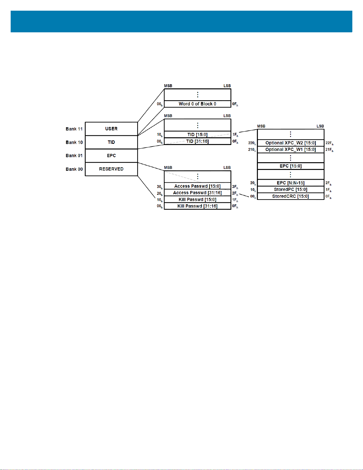
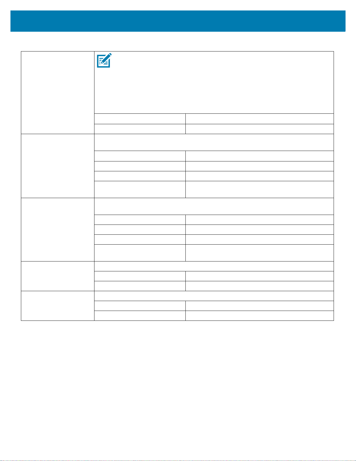
Gen 2 Memory Map
Figure 1 shows how information is stored on a Gen 2 tag.
Figure 1 Gen 2 Memory Map
Introduction to RFIDIntroduction to RFID
8
Page 9

Using RFID Features
This section guides you through some ideas to consider and some tasks that you may need to perform
before you begin using RFID labels. When you have completed this section, you will be ready to program
your RFID label formats.
Performing Firmware Updates
Zebra may update printer firmware periodically to add new functionality or to fix any known issues with
older firmware. At any time, you may download the most recent firmware for your RFID printer. For the
firmware files and the downloading instructions, go to http://www.zebra.com/firmware.
IMPORTANT: Download only the firmware designed for your printer. Downloading inappropriate firmware
may disable your printer or some or all of the RFID functionality. Before downloading new firmware, print a
printer configuration label and verify that the new printer firmware version is appropriate for your printer.
9
Page 10

Using RFID Features
RFID Label Selection
To select RFID labels for your printer, consider the RFID transponder (commonly called the RFID tag) and
where the transponder is placed in the label. Run tests to determine if the RFID labels that you selected
work as you expected before you purchase a large quantity of them. This section provides a brief overview
of things that you should take into account. Additional RFID media considerations specific to your printer
may be found at http://www.zebra.com/transponders/.
IMPORTANT: To use Silverline RFID media, you must use a ZT410 printter with the Silverline Printing
Solution or a ZT411 with the On-metal Tagging Solution. Other RFID printers may not handle this media
correctly.
Considering RFID Transponder Characteristics
Before you purchase Gen 2 RFID labels, determine which RFID transponder (tag) to use. Many RFID
transponders look similar, but they behave differently. For different transponders, the following
characteristics vary:
• the amount of programmable memory (which corresponds to the amount of data that can be encoded in
it)
• the way that data is segmented
• custom commands that can be used (such as block lock)
Select the transponder that best suits your needs.
Accounting for Transponder Inlay Position
Communication between the RFID label and the printer is established when the RFID label’s transponder
lines up with the printer’s RFID antenna or active antenna element. The optimal tag programming position
varies with the transponder size, its configuration, and the type of chip used. Figure 2 on page 11 shows
the physical specifications that should be taken into account for each transponder when deciding where to
place the transponder on a label.
For center-justified printers, the RFID inlay should always be centered horizontally in the label.
IMPORTANT: Print quality may be affected by printing directly over the transponder. In particular, there is
an area on each label immediately around the location of the IC chip where the printer may print with low
quality. Design your printed label around the location of the chip in the type of approved RFID label that
you select.
Testing RFID Labels
Before you purchase a large quantity of Gen 2 RFID labels, test a small batch to make sure that they
function as you need them to. You may need to adjust the transponder location or change transponders if
the RFID labels do not work in your application.
10
Page 11
Using RFID Features
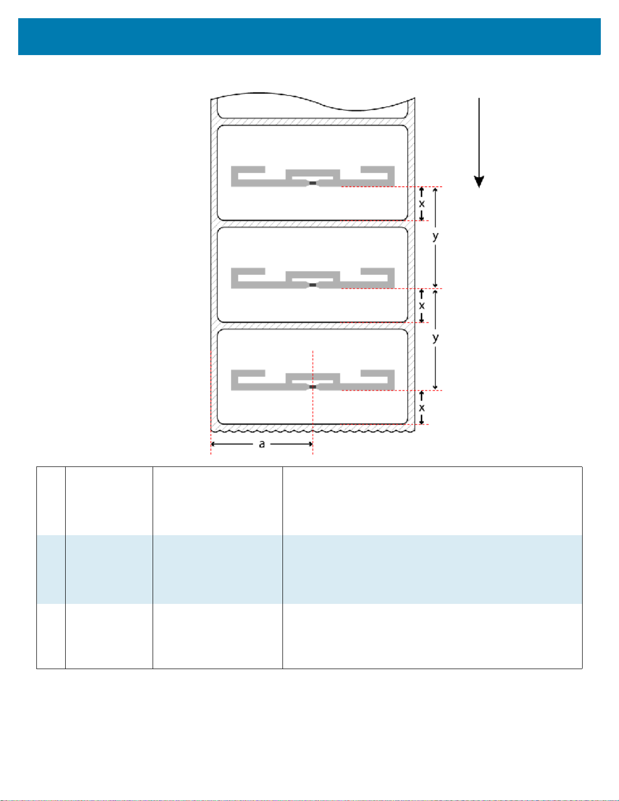
feed direction
Figure 2 Transponder Placement Guidelines
a
Inlay Center Left inner edge to
transponder (inlay) center.
Viewed from face stock
side, feed direction down.
x
Inlay Position Label Start to transponder
antenna leading edge.
y
Inlay Pitch Distance from the leading
edge of one transponder
antenna to the next.
RF coupling with the transponder can change horizontally across
the width of the label. This dimension is relative to the center of
the transponder antenna, which is not always the same as the
chip location.
This measurement is typically defined with a ±3 mm tolerance.
The Inlay Position ensures proper RF encoding with the
transponder in the current label. This dimension is relative to the
leading edge of the transponder antenna and is the optimal
distance from the print line to the antenna during encoding.
This measurement is typically defined with a ±3 mm tolerance.
If transponders are spaced too closely together, coupling to
multiple transponders can sometimes occur. This dimension
defines the minimum pitch required to ensure coupling only with
the transponder in the current label. The minimum pitch for
printers supported by this manual is 16 mm (0.63 in.)
11
Page 12

Using RFID Features
Maximizing RFID Potential
After an RFID label is encoded, how well it functions depends where the label is placed on an item, the
contents of the item (such as metals or liquids), the location of the RFID readers, and how the label is
stored.
Avoiding Radio Frequency Interference
Radio Frequency (RF) interference can be caused by many sources. This interference can affect RFID
performance by limiting the range of the RFID tags or preventing reading/writing to the tags.
• Metal reflects radio frequency signals and is a leading source of RF interference. Foil or metal-based
media should only be used for RFID applications if the tags are designed to work correctly with that
type of media.
• Water and other liquids can absorb RF signals. Some media adhesives and label materials can be
unexpected sources of liquids that cause performance problems.
• Other RF equipment can cause interference if the equipment is positioned too close together. Allow
sufficient physical space between the RFID printer and other RF products that share the same
bandwidth (such as antennas, readers, wireless LANs, or other RFID printer/encoders).
Storing or Handling RFID Labels Correctly
Store RFID labels at temperatures ranging from 60 to 203 °F (15.5 to 95 °C) in environmentally stable
conditions.
Limit RFID label exposure to electrostatic discharge (ESD). Low-humidity environments may require the
use of antistatic mats, straps, or clothing to help counter ESD.
Using the Correct RFID Settings
You can perform two types of calibration on an RFID printer. Media calibration sets the printer for the
media criteria, such as label length and interlabel gap. RFID tag calibration sets the printer for RFID
criteria, such as the optimal programming position.
For best results, run tag calibration each time you change RFID media to allow the printer to select the
best programming position and other RFID settings for you. If tag calibration does not produce the desired
results, you can adjust the values manually.
NOTE: In the ZD500R printer with firmware version V74.19.6Z, any time that a new label length is
measured, the programming position returns to the default value. This can happen in the following
situations:
• any calibration methods that measure length
•
^SS parameter for Label Pitch Length
With all other printers and firmware versions supported by this manual, the program position is persistent.
12
Page 13

Using RFID Features
Setting the RFID Values Using Tag Calibration
Before running tag calibration, calibrate your printer for the media being used, close the printhead, and
feed at least one label to make sure that tag calibration will begin from the correct position. For more
information on media calibration, refer to the User Guide for your printer.
Perform tag calibration using one of the following ways:
• using the
• using the
host computer.
• using the
page 100).
During the tag calibration procedure, the printer feeds an RFID label 1 mm at a time while taking readings
(via READ TAG and WRITE TAG commands) to profile the location of the RFID transponders in the media.
This process ensures that only the current tag will be encoded, not the tag before or after it. Based on the
results, the printer selects optimal values for the following items for the media being used:
• the programming position
• the read/write power levels
• the antenna element (for printers with more than one antenna element)
These values are saved to nonvolatile memory (the value is saved even if the power is turned off) and are
used for all subsequent labels unless a label format specifies a different value.
If the tag cannot be read during the RFID tag calibration process, RFID calibration fails, and the printer
defaults are used. Try running the RFID tag calibration again with another RFID label.
RFID CALIBRATE user menu option (see RFID Tag Calibration (RFID Calibrate) on page 16)
^HR ZPL command (see ^HR on page 50). This command also returns a results table to the
"run" option in the rfid.tag.calibrate SGD command (see rfid.tag.calibrate on
Setting the RFID Values Manually
You can manually change the RFID settings in several ways. See Adjust the Printer’s RFID Settings on
page 22 for more information.
Restoring the Printer’s Default Programming Position
To restore the printer’s default programming position at any time, use the "restore" option in the
rfid.tag.calibrate SGD command (see rfid.tag.calibrate on page 100).
13
Page 14

Locking RFID Tags
If an RFID tag supports locking, you can lock/unlock or permanently lock (permalock)/permanently unlock
memory banks or blocks/sectors of the tag’s memory.
To perform a lock/unlock command or a permalock command, the access password used for the lock
command must match the access password that is stored on the tag. The default access password that is
stored on tags is 00000000. This value must be changed to something other than zero to perform
lock/unlock functions; however, it can remain zero for permalock functions.
If the access password on a tag needs to be changed, use the following command:
^RFW,H,P^FD<access password>^FS
If the correct password is already encoded on your tag, you do not need to write the password to the tag as
part of the label format, thereby adding to the programming time. Instead, you may simply specify the
password as part of the format using the following command, which saves the time of writing it to the tag:
^RFS,H,P^FD<access password>^FS
For more information, see ^RF on page 58 and ^RL on page 62.
Using RFID Features
14
Page 15
RFID Printer Configuration
This section presents the printer RFID settings that you can change and identifies the ways for changing
them. These ways include the following:
• Through the printer’s display (if the printer has one)
NOTE: The settings shown here may not be in the same order in which you see them on your printer.
•ZPL and Set/Get/Do (SGD) commands
• The printer’s user menus
• The printer’s web pages when the printer has an active wired or wireless print server connection (See
the ZebraNet Wired and Wireless Print Servers User Guide for more information about accessing the
web pages. A copy is available at http://www.zebra.com/manuals.)
Table 1 RFID Settings
RFID Country Code Select the RFID country code (if applicable).
NOTE: A prompt for the country code appears only on some printers the first time
that they are powered up, depending on the world region to which the printers were
shipped. Specify the appropriate country to access the printer’s RFID features.
SGD command used: rfid.country_code on page 67
Printer web page: View and Modify Printer Settings > RFID Setup > RFID
COUNTRY CODE
RFID Status Display the status of the RFID subsystem of the printer.
Related ZPL command(s): ^HL or ~HL on page 35
SGD command used: rfid.error.response on page 69
15
Page 16

Table 1 RFID Settings (Continued)
RFID Printer Configuration
RFID Tag Calibration
(RFID Calibrate)
Initiate tag calibration for RFID media. (Not the same as media and ribbon calibration.)
During the process, the printer moves the media, calibrates the RFID tag position, and
determines the optimal settings for the RFID media being used. These settings include the
programming position, the antenna element to use, and the read/write power level to use.
IMPORTANT: Before running this command, load the printer with RFID media,
calibrate your printer, close the printhead, and feed at least one label to make sure
that tag calibration will begin from the correct position.
Leave all transponders before and after the tag that is being calibrated. This allows
the printer to determine RFID settings which do not encode the adjacent tag. Allow a
portion of media to extend out the front of the printer to allow for backfeed during the
tag calibration procedure.
Related ZPL command(s): ^HR on page 37
SGD command used: rfid.tag.calibrate on page 84
Read RFID Data Read and return the specified tag data from the RFID tag located over the RFID antenna.
No printer movement occurs while tag data is being read. The printhead can be open or
closed.
Accepted values: •
epc = reads the EPC data based on the EPC size
specified in the RFID tag’s protocol bits, up to 160
bits
•
tid information = reads the first 32 bits of the TID
(Tag ID)
•
password status = reads the tag’s access and kill
passwords
•
protocol bits = reads the protocol bits from the
EPC memory banks and converts that value to the
EPC size
•
memory bank sizes = reads the EPC, TID, and user
memory banks sizes
•
up = sets the command to the previous test
•
down = sets the command to the next test
Related ZPL command(s): ^RF on page 46
SGD command used: rfid.tag.read.content on page 86 and
rfid.tag.read.execute on page 87
16
Page 17

RFID Printer Configuration
Table 1 RFID Settings (Continued)
RFID Test During the RFID test, the printer attempts to read and write to a transponder. No printer
movement occurs with this test.
Accepted values: •
SGD command used: rfid.tag.test.content on page 92 and
quick = performs a read EPC test and a write EPC
test (using random data)
•
read = performs a read EPC test
•
write = performs a write EPC test (using random
data)
•
up = sets the command to the previous test
•
down = sets the command to the next test
rfid.tag.test.execute on page 93
RFID Programming
Position
If the desired programming position (read/write position) is not achieved through RFID tag
calibration, a value may be specified. See Using the Correct RFID Settings on page 12 for
more information.
Accepted values:
F0 to Fxxx (where xxx is the label length in millimeters
or 999, whichever is less)—The printer feeds the label
forward for the specified distance and then begins
programming.
B0 to B30—The printer backfeeds the label for the
specified distance and then begins programming. To
account for the backfeed, allow empty media liner to
extend out of the front of the printer when using a
backward programming position.
NOTE: Backward program positions of
B1 to B30
may not yield the best results with some media.
If a backward programming position does not
yield the desired results, consider redesigning
your label format so that the printer uses a
forward program position of
F0 to Fxxx.
Related ZPL command(s): ^RS on page 54
SGD command used: rfid.position.program on page 74
Printer web page: View and Modify Printer Settings > RFID Setup >
PROGRAM POSITION
17
Page 18
RFID Printer Configuration
Table 1 RFID Settings (Continued)
RFID Antenna Element If the desired antenna is not achieved through RFID tag calibration, a value may be
specified.
NOTE: This applies only to ZT400 and ZT600 series RFID printers, which have
multiple antenna elements. Other printers, which only have one antenna element,
always use an antenna element value of
Accepted values: A1, A2, A3, A4
B1, B2, B3, B4
C1, C2, C3, C4
D1, D2, D3, D4
E1, E2, E3, E4
Related ZPL command(s): ^RW on page 59
SGD command used: rfid.reader_1.antenna_port on page 75
Printer web page: View and Modify Printer Settings > RFID Setup > RFID
ANTENNA
RFID Adaptive Antenna NOTES:
A1.
• This applies only to ZT400 and ZT600 series RFID printers, which have multiple
antenna elements.
• The label length must be 2 in. (51 mm) or longer.
• Activating this feature may slow throughput on damaged or weak RFID tags.
This command enables or disables adaptive antenna selection.If the printer cannot find
RFID tags with the antenna element specified, the printer may try neighboring antenna
elements. If the printer is unsuccessful communicating with the RFID tag after trying the
neighboring antenna elements, the printer voids the label.
Accepted values: •
none = The printer uses only the current antenna
element selection.
•
neighbors = The printer attempts to read the tag
using the antenna elements to the left/right and
above/below the current antenna. The antenna
element that is successful is used for all subsequent
RFID commands until the next unsuccessful
attempt.
Related ZPL command(s): ^RR on page 53
SGD command used: rfid.adaptive_antenna on page 65
Printer web page: View and Modify Printer Settings > RFID Setup >
ADAPTIVE ANTENNA
18
Page 19
RFID Printer Configuration
Table 1 RFID Settings (Continued)
RFID Antenna Sweep NOTE: This feature applies to ZT400 and ZT600 printers. The label must be 2 in.
(51 mm) or longer, and the label format must have a programming position of F0.
This feature enables/disables the antenna sweep feature. If the RFID media loaded in the
printer is known to be in range of an antenna at the F0 programming position, you can avoid
RFID calibration by using the RFID antenna sweep feature. With this feature enabled, when
the first RFID format is sent after a printer powerup or printhead close, the printer scans
through the antennas to find the optimal antenna element.
Accepted values:
Related ZPL command(s): rfid.antenna_sweep on page 66
RFID Read Power If the desired read power is not achieved through RFID tag calibration, a value may be
specified.
Accepted values: 0 to 30
Related ZPL command(s): ^RW on page 59
SGD command used: rfid.reader_1.power.read on page 80
Printer web page: View and Modify Printer Settings > RFID Setup > RFID
RFID Write Power If the desired write power is not achieved through RFID tag calibration, a value may be
specified.
Accepted values: 0 to 30
Related ZPL command(s): ^RW on page 59
on, off
READ PWR
SGD command used: rfid.reader_1.power.write on page 81
Printer web page: View and Modify Printer Settings > RFID Setup > RFID
WRITE PWR
RFID Valid Counter Resets the RFID valid label counter to zero.
Related ZPL command(s): ~RO on page 52
SGD command used: odometer.rfid.valid_resettable on page 63
RFID Void Counter Resets the RFID void label counter to zero.
Related ZPL command(s): ~RO on page 52
SGD command used: odometer.rfid.void_resettable on page 64
19
Page 20

Creating Basic RFID Label Formats
Use the ZPL samples in this section as a base for programming your own RFID label formats.
For specific information about individual ZPL commands, see ZPL Commands for RFID on page 34.
Create and Send an RFID Label Format
The following pages contain sample RFID label formats that you can modify to create your own RFID label
formats.
To create an RFID label based on a sample label, complete these steps:
1. Using any word processor or text editor that is capable of creating ASCII-only files (for example, use
Microsoft
sample.
2. Save the file to your computer.
When naming the file, use
file
3. Set up the printer, and turn the power On (I).
4. Copy the file to the printer. One way to do this is by using the Zebra Setup Utilities (to download go to
http://www.zebra.com/us/en/products-services/software/manage-software/zebra-setup-utility.html).
5. Compare your label results with those shown in the sample. If your results are not the same as those
shown, confirm that the file you created is identical to the format shown, and then repeat the printing
procedure.
6. Check the RFID data on your label.
a. Open the printhead, and place the label above the antenna in the printer.
b. Use one of the methods given in Read RFID Data on page 16 to view the transponder data.
c. Compare your RFID data with that shown in the sample. If your data does not look like what is
7. When you are certain that the file you created is correct, substitute your data in the label format where
necessary.
®
Word and save as a .txt file), type in the label format exactly as shown in the desired
.zpl as the extension for the file (for example, you may choose to name a
format1.zpl).
shown, confirm that the file you created is identical to the format shown, and then resend the label
format to the printer.
20
Page 21
Creating Basic RFID Label FormatsCreating Basic RFID Label Formats
Simple write example
▼
READ RFID DATA
EPC
▲
11223344556677889900
1122
READ
Sample RFID Label Formats
Use the formats in this section to assist you in creating your own RFID label formats.
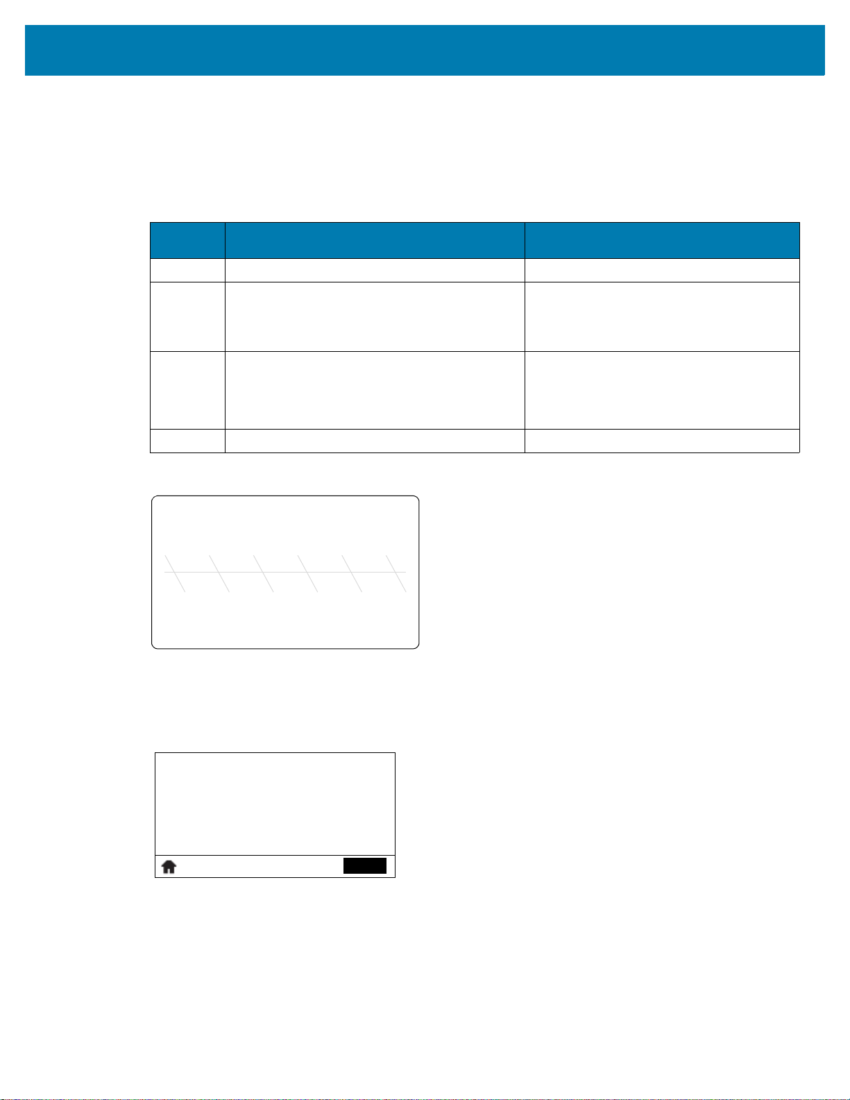
RFID Label Format 1—Encode a Gen 2 Tag in Hexadecimal
Line
Number
1
2
^XA
^FO50,50
^A0N,65
^FDSimple write example
^FS
3
^RFW,H
^FD112233445566778899001122
^FS
4
Resulting Label
^XZ
Type This ZPL Code Function of ZPL Code
Indicates start of label format.
Prints “Simple write example” on the label
at location 50,50.
W,H = write hex
Encodes the 12 bytes of data (96 bits) to
the tag. The data written is:
112233445566778899001122
Indicates end of label format.
Programmed to Transponder
112233445566778899001122
Sample Control Panel Display
21
Page 22

Creating Basic RFID Label FormatsCreating Basic RFID Label Formats
Simple write example
▼
READ RFID DATA
EPC
▲
30302072666964206461
7461
READ
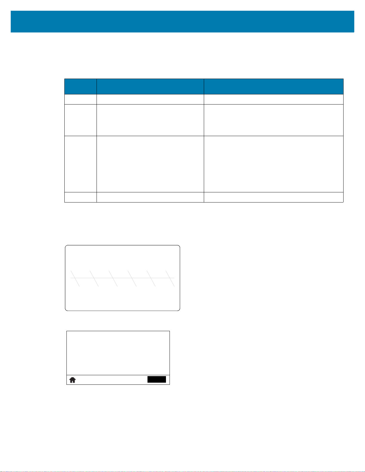
RFID Label Format 2—Encode a Gen 2 Tag in ASCII
This label format is different in what shows on the control panel. The control panel always displays RFID
data in hexadecimal.
Line
Number
1
2
^XA
^FO50,50
^A0N,65
^FDSimple write example
^FS
3
^RFW,A
^FD00 rfid data
^FS
4
Resulting Label
^XZ
Type This ZPL Code Function of ZPL Code
Indicates start of label format.
Prints “Simple write example” on the label at
location 50,50.
W,A = write ASCII
Encodes 00 rfid data to the tag in hexadecimal
format, which is 12 bytes of data (96 bits). The
data written is:
303020726669642064617461
Indicates end of label format.
Programmed to Transponder
303020726669642064617461
Sample Control Panel Display
22
Page 23
Creating Basic RFID Label FormatsCreating Basic RFID Label Formats
112233445566778899001122
▼
READ RFID DATA
EPC
▲
11223344556677889900
1122
READ
RFID Label Format 3—Read Data from Tag and Print Data on Label
This example assumes that the tag created using RFID Label Format 1—Encode a Gen 2 Tag in
Hexadecimal on page 21 is being read.
Line
Number
1
2
^XA
^FO50,50
Type This ZPL Code Function of ZPL Code
^A0N,40
^FN0
^FS
3
^FN0
^RFR,H
^FS
4
Read from Transponder
^XZ
112233445566778899001122
Resulting Label
Indicates start of label format.
^FN0 is a placeholder field variable for the tag data
that will be read in the following line. When the
label prints, the data read from the tag will be
printed at location 50,50.
R,H = read hexadecimal
The read results are put into field variable 0 (
At this point, the printer substitutes previous
instances of
from this field. If necessary, the data read from the
tag will be padded with zeroes to the maximum bit
size.
Indicates end of label format.
^FN0 in the label format with the data
^FN0).
Sample Control Panel Display
23
Page 24

Creating Basic RFID Label FormatsCreating Basic RFID Label Formats
0data
RFID Label Format 4—Encode Tag, Read Tag, and Print Data on Label
Line
Number
1
2
^XA
^FO60,60
Type This ZPL Code Function of ZPL Code
^A0N,40
^FN7
^FS
3
^RFW,A
^FD0data
^FS
4
^FN7
^RFR,A
^FS
5
Programmed to Transponder
^XZ
Indicates start of label format.
When the label prints, the data read from the tag at
field variable 7 (
60,60.
W,A = write ASCII
Encodes 0data into the block in hexadecimal
format, padded with 8 bytes of zeroes to make the
data 12 bytes. The data written is:
306461746100000000000000
R,A = read ASCII
Reads the tag data into field variable 7 (
After this occurs, any fields in this label format that
^FN7 will be replaced with this read data.
have
Because ASCII format was specified, the
hexadecimal value is converted back to ASCII
format before being printed on the label.
Indicates end of label format.
^FN7) will be printed at location
^FN7).
306461746100000000000000
Read from Transponder
306461746100000000000000
Resulting Label
24
Page 25

Creating Basic RFID Label FormatsCreating Basic RFID Label Formats
▼
READ RFID DATA
EPC
▲
30646174610000000000
0000
READ
Sample Control Panel Display
25
Page 26

Creating Basic RFID Label FormatsCreating Basic RFID Label Formats
010203040500000000000000
RFID Label Format 5—Encode Tag, Read Tag, and Return Results to Host
Line
Number
1
2
3
4
5
6
Type This ZPL Code Function of ZPL Code
^XA
^FO50,50
^A0N,65
^FN3
^FS
^RFW,H
^FD0102030405
^FS
^FN3
^RFR,H
^FS
^HV3
^XZ
Indicates start of label format.
When the label prints, the data read from the tag at
field variable 3 (
50,50.
W,H = write hex
Encodes 12 bytes of data (96 bits) to the tag with
7 bytes of zeroes as padding. The data written is:
010203040500000000000000
R,H = read hexadecimal
Reads the tag data into field variable 3 (
After this occurs, any fields in this label format that
^FN3 will be replaced with this read data.
have
Returns the value in ^FN3 to the host computer.
Data is sent over whichever communication
channel is established with the host (such as
parallel, serial, USB, Ethernet). In this example,
010203040500000000000000 would be returned to
the host.
Indicates end of label format.
^FN3) will be printed at location
^FN3).
Programmed to Transponder
010203040500000000000000
Read from Transponder
010203040500000000000000
Resulting Label
26
Page 27

Creating Basic RFID Label FormatsCreating Basic RFID Label Formats
▼
READ RFID DATA
EPC
▲
01020304050000000000
0000
READ
Sample Control Panel Display
Sent to Host Computer
010203040500000000000000
27
Page 28

Troubleshooting
This section provides information about RFID operational errors that you might need to troubleshoot. For
other types of problems, consult the User Guide for your printer.
RFID Problems
Table 2 identifies problems that may occur with RFID printers, the possible causes, and the recommended
solutions.
Table 2 RFID Problems
Problem Possible Cause Recommended Solution
The printer encodes the
wrong tag.
The printed data does not
match the encoded data.
RFID tag calibration fails. Some RFID inlays are more
The printer is not calibrated for the
media being used.
sensitive than others. The RFID
inlay being calibrated may be more
or less sensitive than others on the
same roll of media.
On ZQ511, ZQ521, and ZQ630
printers, the RFID inlays are placed
too close together.
1. Perform media calibration. Refer to the User Guide
for your printer for media calibration instructions.
2. Perform RFID tag calibration. (See Setting the
RFID Values Using Tag Calibration on page 13.)
3. If necessary, adjust the RFID settings manually.
(See RFID Printer Configuration on page 15.)
Perform RFID tag calibration again. (See Setting the
RFID Values Using Tag Calibration on page 13.)
1. Manually set the program position and read/write
power levels. (See RFID Printer Configuration on
page 15.)
2. Verify that the tags are being programmed with the
correct information.
Change the spacing of the RFID inlays.
28
Page 29

Table 2 RFID Problems (Continued)
Problem Possible Cause Recommended Solution
Low yields. Too many
RFID tags per roll are
voided.
Some RFID inlays are more
sensitive than others and may
require special printer settings.
TroubleshootingTroubleshooting
1. Perform RFID tag calibration. (See Setting the
RFID Values Using Tag Calibration on page 13.)
2. If necessary, adjust the RFID settings manually.
(See RFID Printer Configuration on page 15.)
3. If the problem persists, consider using a different
tag type. Contact an authorized Zebra RFID
reseller for more information.
The printer stops at the
RFID inlay.
Radio frequency (RF) interference
from another RF source.
The printer is using outdated
printer firmware.
The printer calibrated the label
length only to the RFID inlay
instead of to the interlabel gap.
Do one or more of the following as necessary:
• Move the printer away from fixed RFID readers.
• Make sure that the media door is closed at all
times during RFID programming.
Go to www.zebra.com/firmware for updated firmware.
1. Perform media calibration. Refer to the User Guide
for your printer for media calibration instructions.
2. Perform RFID tag calibration. (See Setting the
RFID Values Using Tag Calibration on page 13.)
29
Page 30

Table 2 RFID Problems (Continued)
Problem Possible Cause Recommended Solution
The RFID-enabled printer
voids every label.
The printer is not calibrated for the
media being used.
TroubleshootingTroubleshooting
1. Perform media calibration. Refer to the User Guide
for your printer for media calibration instructions.
2. Perform RFID tag calibration. (See Setting the
RFID Values Using Tag Calibration on page 13.)
3. If necessary, adjust the RFID settings manually.
(See RFID Printer Configuration on page 15.)
You are using an incorrect value for
the programming position or
another RFID setting.
You are sending RFID ZPL or SGD
commands that are incorrect.
The settings are incorrect in your
label designer software.
Radio frequency (RF) interference
from another RF source.
The printer is unable to
communicate with the RFID
reader/encoding module.
1. Perform RFID tag calibration. (See Setting the
RFID Values Using Tag Calibration on page 13.)
2. If necessary, adjust the RFID settings manually.
(See RFID Printer Configuration on page 15.)
1. Check your label formats. See ZPL Commands for
RFID on page 34 or SGD Commands for RFID on
page 61.
2. For sample label formats, see Sample RFID Label
Formats on page 21.
The software settings override the printer settings.
Make sure that the software and printer settings
match.
Do one or more of the following as necessary:
• Move the printer away from fixed RFID readers or
other RF sources.
• Make sure that the media door is closed at all
times during RFID programming.
1. Turn off (O) the printer.
2. Wait 10 seconds.
3. Turn on (I) the printer.
The DATA light flashes
indefinitely after you
attempt to download
printer firmware.
The download was not successful.
For best results, cycle power on the
printer before downloading any
firmware.
30
4. If the problem persists, you may have a bad
encoding module or a loose connection between
the encoding module and the printer. Contact
Technical Support or an authorized Zebra RFID
service technician for assistance.
1. Turn off (O) the printer.
2. Wait 10 seconds.
3. Turn on (I) the printer.
4. Attempt to download the firmware again.
5.
If the problem persists, contact Technical Support.
Page 31

Table 2 RFID Problems (Continued)
Problem Possible Cause Recommended Solution
RFID parameters do not
appear in Setup mode,
and RFID information
does not appear on the
printer configuration
label.
The printer does not void
RFID labels that are not
programmed correctly.
An incorrect version of firmware
was loaded on the printer.
The printer is unable to
communicate with the RFID
subsystem.
TroubleshootingTroubleshooting
1. Go to www.zebra.com/firmware
2. Download the correct printer firmware, if
necessary.
3. If the problem persists, contact Technical Support.
1. Turn off (O) the printer.
2. Wait 10 seconds.
3. Turn on (I) the printer.
4. If the problem persists, you may have a bad RFID
reader or a loose connection between the RFID
reader and the printer. Contact Technical Support
or an authorized service technician for assistance.
.
RFID is disabled. The SGD
command
"off".
rfid.enable is set to
1. Change
page 68.)
2. Restart your printer for changes to take effect.
rfid.enable to "on". (See rfid.enable on
RFID Error Codes and Messages
In the event of an RFID error, the printer does the following:
• displays an RFID error or status message on the second line of the
display
• returns RFID error codes to the RFID data log (see ^HL or ~HL on page 35 for more information about
the RFID data log)
Table 3 lists the error codes. Numbers that appear in the format “
individually.
Table 3 RFID Error Codes
Error Code
XXXXXXXX READER ERR XXXXXXXX
00000000 RFID OK The RFID operation completed successfully.
00001239 ENCODER ERROR An error occurred in the RFID encoder module firmware.
RFID Error or
Status Message
Description/Action Required
XXXXXXXX is 8 hex characters returned from the reader.
This error can indicate a read/write error with your RFID tag, or it could
indicate an internal problem with the RFID reader. If the problem persists,
contact Technical Support.
RFID STATUS control panel
READER ERR xxxxxxxx” are not listed
00001240 BAD RFID DATA The data that was attempted to be written to a tag is not valid.
00001241 RFID TEST ERROR An error occurred during an RFID test.
00001242 COUNTRY CODE ERROR The value of the country code that was sent to the RFID reader is not valid,
or the value was not specified. See RFID Country Code on page 15 for
more information.
00001244 NO READER PRESENT The printer does not detect an RFID reader.
02000100 DATA AMOUNT ERROR The wrong amount of data was specified in an RFID reader command.
31
Page 32

Table 3 RFID Error Codes (Continued)
TroubleshootingTroubleshooting
Error Code
02000101 INVALID OPCODE The command sent to the RFID reader module was invalid.
02000102 UNKNOWN OPCODE The command sent to the RFID reader module is not known by the module
02000103 RFID PWR TOO HIGH An attempt was made to set the power of the RFID reader to a value that is
02000104 INVALID FREQUENCY The frequency selected in an RFID command to reader module is not valid.
02000105 INVALID PARAMETER A parameter of an RFID command for the reader module is not valid.
02000106 RFID PWR TOO LOW An attempt was made to set the power of the RFID reader to a value that is
02000109 INVALID COMMAND The command sent to the RFID reader module was invalid.
02000200 BAD IMAGE CRC The RFID reader firmware had a bad validation checksum.
02000201 READER FW ERROR An error occurred in the RFID reader module.
02000300 RFID FLASH ERROR An error occurred while attempting to write firmware to the RFID reader
02000301
02000302
02000303
02000304
02000305
02000306
02000400 NO TAG FOUND The reader attempted to locate an RFID tag and was unable to do so.
RFID Error or
Status Message
Description/Action Required
firmware.
too large.
too small.
module.
02000401 PROTOCOL UNDEFINED The RFID reader was not properly told the type of RFID tag.
02000402 INVALID PROTOCOL The type of RFID tag that the RFID reader was told to expect is not valid.
02000403 LOCK ERROR An error occurred while attempting to change the lock bits on the tag.
02000404 NO DATA READ An attempt to read data from a tag could not find any data.
02000405 AFE NOT ON The reader module does not have the AFE on.
02000406 WRITE FAILED The tag write failed.
02000407 NOT IMPLEMENTED The RFID reader command that was sent to the reader is not implemented
in this version of reader firmware.
02000408 INVALID WRITE DATA The data that was attempted to be written to a tag is not valid.
02000409 INVALID ADDRESS The memory address for data to be written to a tag is not valid.
02000410 PROTOCOL BAD EPC The protocol definition is inconsistent with the size of the EPC data area.
02000411 PROT BAD NUM DATA The protocol definition is inconsistent with the amount of data sent.
02000420 GEN2 PROTOCOL ERR An error was made in the specification of a Generation 2 tag protocol.
02000423 GEN2 MEMORY BAD PC An error was made in the specification of a Generation 2 tag protocol control
bit.
02000424 GEN2 MEMORY LOCKED The Generation 2 tag memory area is locked.
02000430 GEN2 UNKNOWN ERROR An unknown error was made with a Generation 2 tag.
02000500 TRANSMITTER ON The RFID radio transmitter is on.
32
Page 33

Table 3 RFID Error Codes (Continued)
TroubleshootingTroubleshooting
Error Code
02000503 NO ANTENNA FOUND The RFID reader module found that no antenna was connected.
02000504 RFID TOO HOT The RFID reader module is too hot.
02000505 HIGH RETURN LOSS The amount of energy being reflected by the antenna connection is higher
02000507 BAD ANTENNA CFG An attempt was made to set the reader module to an invalid antenna
02000600 NOT ENOUGH TAGS The RFID module memory contained data from fewer tags than was
02000601 TAG ID BUFFER FULL The RFID module memory is full.
02000602 REPEATED TAG ID An attempt was made to write data to the RFID module memory with an ID
02000603 TOO MANY TAG IDS The RFID reader was asked to read more tags into module memory than
02000604 BLOCKED RESPONSE The RFID module response is blocked.
02001001 RDR COMM TIMEOUT An attempt to communicate with the reader module took too much time.
02001238 PRINTER ERROR The printer caused an error.
02001242 COUNTRY CODE ERROR The RFID country code is not selected.
0200010A INVALID BAUD RATE An attempt was made to set the serial communication baud rate of the RFID
0200010B INVALID REGION An attempt was made to set the region of the RFID reader to a value that is
0200010C BAD LICENSE KEY The RFID reader firmware's license key does not match the RFID reader
RFID Error or
Status Message
Description/Action Required
than acceptable.
configuration.
requested by printer firmware.
that is already present in the memory.
the module could hold.
reader to a value that is not valid.
not valid.
firmware.
0200040A GENERAL TAG ERROR Miscellaneous error while attempting to read or write to a tag.
0200040B DATA TOO LARGE Too much data was attempted to be written to a tag.
0200040F PROT BIT DCDNG BAD Protocol bit decoding failure.
0200042B GEN2 LOW POWER The Generation 2 tag is set to low power mode.
0200042F GEN2 ERROR An unspecified error was made with a Generation 2 tag.
02007F00 SYS UNKNOWN ERROR A firmware routine in the RFID reader module firmware returned an
unknown error.
02007F01 TM ASSERT FAILED An unexpected internal error has occurred in the RFID reader module
firmware.
33
Page 34

ZPL Commands for RFID
This section contains the ZPL II commands for RFID-specific applications.
34
Page 35

^HL or ~HL
Return RFID Data Log to Host
Description: The printer can log RFID data and store it in the printer’s RAM. These commands request
that the RFID data log be returned to the host computer. The
while the
The firmware version determines the way that these commands function:
^HL command is processed after all of the previous formats (^XA ... ^XZ) have been processed.
ZPL Commands for RFID
~HL command is processed immediately,
• In firmware X.20.16Z and later, for security, logging is disabled by default. The
current data log and restarts data recording. The
log. The RFID host logs can be enabled or disabled by the "rfid.log.enabled" SGD command (see
rfid.log.entries on page 73).
• In firmware X.20.15Z and earlier, logging is enabled by default. Both commands clear the current data
log and restart data recording.
Format:
In the log, RFID data displays in this format:
[date&time][RFID operation],[program position],[antenna element],
[read or write power], [RFID status],[data]
where
•
•
^HL or ~HL
[date&time]*
a time stamp for the log entry
* With some older versions of firmware, this parameter does not display.
[RFID operation]
B = a ^RLB command was issued (see ^RLB – Permanently Lock Specified Memory Sections on
page 51)
E = log file reset
L = lock
M = a ^RLM command was issued (see ^RLM – Lock/Unlock the Specified Memory Bank on page 50)
R = read
W = write
~HL command does not automatically clear the data
^HL command clears the
•
[program position],[antenna element],[read or write power]*
Additional information about the program position, the antenna, and the read or write power follows the
RFID operation.
Such as:
R,F1,D3,27,00000000,DATA
where
F1 = the program position, D3 = the antenna, and 27 is the write power.
* With some older versions of firmware, these parameters do not display.
• [RFID status]
######## = an RFID error code (see RFID Error Codes and Messages on page 43)
FFFFFFFF (or limited to length FFFF for some printers) = indicates that the log file was reset
•
[data]
the data read or written
Comments:
• Data is shown in the format specified by the
^RFW command (ASCII, Hex, or EPC).
35
Page 36

ZPL Commands for RFID
• If the RFID data log exceeds the maximum size, the following occurs:
• In firmware X.20.16Z and later, when the data log reaches 1500K, one or more older entries are
deleted to make room for the newest entry.
• In firmware X.20.15Z and earlier, when the data log reaches 64K, the RFID data log is cleared
automatically, and data recording restarts. When this happens, the following appears in the log:
E,FFFFFFFF,Logfile automatically reset
• In firmware X.20.15Z and earlier, If the printer loses power, the log is lost. If the log results are
important to you, retrieve the information frequently.
36
Page 37

^HR
Calibrate RFID Tag Position
Description: Use this command to initiate tag calibration for RFID media. During the tag calibration
process (which can take up to 5 minutes on some printers, depending on the type of RFID inlay and the
label size) the printer moves the media, reads the tag’s TID to determine chip type, calibrates the RFID tag
position, and determines the optimal settings for the RFID media being used. Depending on the printer,
these settings include the programming position, the antenna element to use, and the read/write power
level to use.
ZPL Commands for RFID
Results of the
rfid.tag.calibrate SGD command performs the same calibration but does not create a results table. To
restore the printer’s default programming position at any time, use the
rfid.tag.calibrate SGD command (see rfid.tag.calibrate on page 84).
Before running this command, load the printer with RFID media, calibrate your printer, close the printhead,
and feed at least one label to make sure that tag calibration will begin from the correct position. For more
information on media calibration, refer to the User Guide for your printer.
IMPORTANT: Leave all transponders before and after the tag that is being calibrated. This allows the
printer to determine RFID settings which do not encode the adjacent tag. Allow a portion of media to
extend out the front of the printer to allow for backfeed during the tag calibration procedure.
Format:
a = start string This parameter specifies the user text to appear before the results table.
b = end string This parameter specifies the user text to appear after the results table.
^HR tag calibration are returned to the host computer. The "run" option in the
"restore" option in the
^HRa,b,c,d,e
Parameters Details
Values: any string less than 65 characters
Default: start
Values: any string less than 65 characters
Default: end
37
Page 38

ZPL Commands for RFID
Parameters Details
c = start position This parameter specifies the start position of the calibration range. All
numeric values are in millimeters. Forward or backward designations
assume that the label's initial position is with the leading edge at the print
line.
Values:
•Forward:
F0 to Fxxx (where xxx is the label length in millimeters or 999,
whichever is less)
The printer feeds the label forward for the specified distance and then
begins tag calibration.
• Backward:
B0 to B30
The printer backfeeds the label for the specified distance and then
begins tag calibration. To account for the backfeed, allow empty media
liner to extend out of the front of the printer when using a backward
programming position. For printers that do not use backfeed during
RFID calibration, the media is moved forward until it is in the same
relative position for the following label.
Default:
• For ZT400 Series and ZT600 Series printers with RFID option:
• For all other supported printers:
d = end position This parameter specifies the end position of the calibration range (last
B20
B30
program position to check). All numeric values are in millimeters. Forward
or backward designations assume that the label's initial position is with the
leading edge at the print line.
Values:
•Forward:
F0 to Fxxx (where xxx is the label length in millimeters or 999,
whichever is less)
The printer performs tag calibration until it reaches the specified end
position and then ends the process.
• Backward:
B0 to B30
The printer performs tag calibration until it reaches the specified end
position and then ends the process. Valid only with a backward start
position that is greater than the end position.
• Automatic:
A
The printer automatically ends the tag calibration process after
successfully reading and encoding a consecutive range of 5 mm on the
label. The printer also ensures that no other tags can be programmed at
the programming position with the calibration-determined power levels.
Default:
A
38
Page 39

Parameters Details
e = antenna and
read/write power level
detection
ZPL Commands for RFID
This parameter specifies whether to select the antenna and read/write
power levels automatically or manually.
NOTE: The ZD500R, ZQ511/ZQ521, and ZQ630 printers have only
one antenna, so this parameter applies only to the read/write power
level settings.
Values:
•
A = Automatic. The printer automatically scans through the antennas
and read/write power during calibration.
•
M = Manual. The printer uses the current antenna and read/write power
level settings.
Default:
A
39
Page 40

ZPL Commands for RFID
Example: When the ^HR command is sent to the printer, the printer performs tag calibration and returns a
results table such as the following:
start
position=B14 MM,A1,18,25
tid information=E200.3414:Alien
leading edge
Tag 1 ,Tag 2 ,Tag 3 ,Tag 4 ,Tag 5 ,Tag 1 ,Tag 2 ,Tag 3 ,Tag 4 ,Tag 5 ,
EPC,7109 ,BA29 ,6FD0 ,58AE ,9CDE ,7109 ,BA29 ,6FD0 ,58AE ,9CDE ,
B30,A1,12,18,A1,29, ,A1, , ,A1, , ,A1, , ,B1, , ,B1,17,24,B1, , ,B1, , ,B1, , ,
B29,A1,13,18,A1,25, ,A1, , ,A1, , ,A1, , ,B1, , ,B1,14,19,B1, , ,B1, , ,B1, , ,
B28,A1,15,20,A1,23,29,A1, , ,A1, , ,A1, , ,B1, , ,B1,09,15,B1, , ,B1, , ,B1, , ,
B27,A1,17,22,A1,23,29,A1, , ,A1, , ,A1, , ,B1, , ,B1,08,14,B1, , ,B1, , ,B1, , ,
B26,A1,19,25,A1, , ,A1, , ,A1, , ,A1, , ,B1, , ,B1,09,15,B1,28, ,B1, , ,B1, , ,
B25,A1,22,28,A1,22,27,A1, , ,A1, , ,A1, , ,B1, , ,B1,11,18,B1,26, ,B1, , ,B1, , ,
B24,A1,26, ,A1,13,19,A1, , ,A1, , ,A1, , ,B1, , ,B1,15,21,B1,27, ,B1, , ,B1, , ,
B23,A1, , ,A1,08,14,A1, , ,A1, , ,A1, , ,B1, , ,B1,18,24,B1, , ,B1, , ,B1, , ,
B22,A1, , ,A1,05,11,A1, , ,A1, , ,A1, , ,B1, , ,B1,21,28,B1,19,24,B1, , ,B1, , ,
B21,A1, , ,A1,05,11,A1, , ,A1, , ,A1, , ,B1, , ,B1,25, ,B1,11,17,B1, , ,B1, , ,
B20,A1, , ,A1,06,12,A1, , ,A1, , ,A1, , ,B1, , ,B1,30, ,B1,07,13,B1, , ,B1, , ,
B19,A1, , ,A1,08,15,A1, , ,A1, , ,A1, , ,B1, , ,B1, , ,B1,05,11,B1, , ,B1, , ,
B18,A1, , ,A1,15,22,A1, , ,A1, , ,A1, , ,B1, , ,B1, , ,B1,05,10,B1, , ,B1, , ,
B17,A1, , ,A1,22,28,A1, , ,A1, , ,A1, , ,B1, , ,B1, , ,B1,05,11,B1, , ,B1, , ,
B16,A1, , ,A1,16,23,A1, , ,A1, , ,A1, , ,B1, , ,B1, , ,B1,07,13,B1, , ,B1, , ,
B15,A1, , ,A1,13,19,A1, , ,A1, , ,A1, , ,B1, , ,B1, , ,B1,13,20,B1, , ,B1, , ,
B14,A1, , ,A1,12,19,A1, , ,A1, , ,A1, , ,B1, , ,B1, , ,B1,18,23,B1, , ,B1, , ,<---****A1
B13,A1, , ,A1,14,20,A1,24,30,A1, , ,A1, , ,B1, , ,B1, , ,B1,10,16,B1, , ,B1, , ,
B12,A1, , ,A1,15,22,A1,22,29,A1, , ,A1, , ,B1, , ,B1, , ,B1,08,14,B1, , ,B1, , ,
B11,A1, , ,A1,18,25,A1,26, ,A1, , ,A1, , ,B1, , ,B1, , ,B1,08,14,B1, , ,B1, , ,
B10,A1, , ,A1,21,27,A1,26, ,A1, , ,A1, , ,B1, , ,B1, , ,B1,11,17,B1,26, ,B1, , ,
B09,A1, , ,A1,24, ,A1,15,21,A1, , ,A1, , ,B1, , ,B1, , ,B1,14,20,B1,25, ,B1, , ,
B08,A1, , ,A1,28, ,A1,09,15,A1, , ,A1, , ,B1, , ,B1, , ,B1,17,23,B1, , ,B1, , ,
B07,A1, , ,A1, , ,A1,06,11,A1, , ,A1, , ,B1, , ,B1, , ,B1,20,26,B1,27,30,B1, , ,
B06,A1, , ,A1, , ,A1,05,11,A1, , ,A1, , ,B1, , ,B1, , ,B1,24,30,B1,16,19,B1, , ,
B05,A1, , ,A1, , ,A1,05,11,A1, , ,A1, , ,B1, , ,B1, , ,B1,28, ,B1,10,14,B1, , ,
B04,A1, , ,A1, , ,A1,08,14,A1, , ,A1, , ,B1, , ,B1, , ,B1, , ,B1,07,11,B1, , ,
B03,A1, , ,A1, , ,A1,12,18,A1, , ,A1, , ,B1, , ,B1, , ,B1, , ,B1,06,11,B1, , ,
B02,A1, , ,A1, , ,A1,20,26,A1, , ,A1, , ,B1, , ,B1, , ,B1, , ,B1,06,10,B1, , ,
B01,A1, , ,A1, , ,A1,18,24,A1, , ,A1, , ,B1, , ,B1, , ,B1, , ,B1,09,13,B1, , ,
F00,A1, , ,A1, , ,A1,14,21,A1, , ,A1, , ,B1, , ,B1, , ,B1, , ,B1,12,17,B1, , ,
F01,A1, , ,A1, , ,A1,13,19,A1, , ,A1, , ,B1, , ,B1, , ,B1, , ,B1,20,25,B1, , ,
F02,A1, , ,A1, , ,A1,13,19,A1,27, ,A1, , ,B1, , ,B1, , ,B1, , ,B1,16,20,B1, , ,
F03,A1, , ,A1, , ,A1,14,21,A1,26,29,A1, , ,B1, , ,B1, , ,B1, , ,B1,11,16,B1, , ,
F04,A1, , ,A1, , ,A1,17,24,A1,27, ,A1, , ,B1, , ,B1, , ,B1, , ,B1,11,15,B1, , ,
F05,A1, , ,A1, , ,A1,19,26,A1, , ,A1, , ,B1, , ,B1, , ,B1, , ,B1,12,16,B1,25, ,
F06,A1, , ,A1, , ,A1,22,29,A1,23,26,A1, , ,B1, , ,B1, , ,B1, , ,B1,15,18,B1,23,28,
F07,A1, , ,A1, , ,A1,26, ,A1,15,19,A1, , ,B1, , ,B1, , ,B1, , ,B1,17,22,B1,23,29,
F08,A1, , ,A1, , ,A1, , ,A1,10,14,A1, , ,B1, , ,B1, , ,B1, , ,B1,20,25,B1, , ,
F09,A1, , ,A1, , ,A1, , ,A1,08,12,A1, , ,B1, , ,B1, , ,B1, , ,B1,24,28,B1,21,26,
F10,A1, , ,A1, , ,A1, , ,A1,08,11,A1, , ,B1, , ,B1, , ,B1, , ,B1,27, ,B1,13,18,
trailing edge
end
In the results table, the tags visible to the antenna elements are numbered, and the EPC number that is
unique to each tag is displayed.
40
Page 41

ZPL Commands for RFID
Each line in the results table gives a row number followed by readings associated with RFID tags that are
visible at that row. Multiple values on a line indicate that multiple tags were visible. The order of the RFID
tags is arbitrary.
[Row],[Antenna Element],[Min Read Power],[Min Write Power], [Antenna Element],[Min Read Power],[Min Write Power] ...
where
• Row = the position from the leading edge of the label where calibration occurred
• Antenna Element = the antenna used
• Minimum Read Power = calibration results (
• Minimum Write Power = calibration results (
The read and write power values are left empty (such as
In the sample results table for this example, at position
0 – 30) for a tag visible from that row
0 – 30) for the same tag
A1,,,) when no tag is found.
B25 (25 mm behind the print line), two RFID tags
are visible to the printer at antenna A1. Tag 1 (EPC 7109) can be read at power level 22 and written to at
power level 28. Tag 2 (EPC BA29) can be read at power level 22 and written to at power level 27. At that
position, Tags 2 and 3 are visible to antenna B1 while Tag 1 is not.
Tag 1 ,Tag 2 ,Tag 3 ,Tag 4 ,Tag 5 ,Tag 1 ,Tag 2 ,Tag 3 ,Tag 4 ,Tag 5 ,
EPC,7109 ,BA29 ,6FD0 ,58AE ,9CDE ,7109 ,BA29 ,6FD0 ,58AE ,9CDE ,
...
B25,A1,22,28,A1,22,27,A1, , ,A1, , ,A1, , ,B1, , ,B1,11,18,B1,26, ,B1, , ,B1, , ,
B24,A1,26, ,A1,13,19,A1, , ,A1, , ,A1, , ,B1, , ,B1,15,21,B1,27, ,B1, , ,B1, , ,
B23,A1, , ,A1,08,14,A1, , ,A1, , ,A1, , ,B1, , ,B1,18,24,B1, , ,B1, , ,B1, , ,
B22,A1, , ,A1,05,11,A1, , ,A1, , ,A1, , ,B1, , ,B1,21,28,B1,19,24,B1, , ,B1, , ,
B21,A1, , ,A1,05,11,A1, , ,A1, , ,A1, , ,B1, , ,B1,25, ,B1,11,17,B1, , ,B1, , ,
...
At position B23, only Tag 2 is visible to antenna A1. Tag 1 is no longer visible.
Tag 1 ,Tag 2 ,Tag 3 ,Tag 4 ,Tag 5 ,Tag 1 ,Tag 2 ,Tag 3 ,Tag 4 ,Tag 5 ,
EPC,7109 ,BA29 ,6FD0 ,58AE ,9CDE ,7109 ,BA29 ,6FD0 ,58AE ,9CDE ,
...
B25,A1,22,28,A1,22,27,A1, , ,A1, , ,A1, , ,B1, , ,B1,11,18,B1,26, ,B1, , ,B1, , ,
B24,A1,26, ,A1,13,19,A1, , ,A1, , ,A1, , ,B1, , ,B1,15,21,B1,27, ,B1, , ,B1, , ,
B23,A1, , ,A1,08,14,A1, , ,A1, , ,A1, , ,B1, , ,B1,18,24,B1, , ,B1, , ,B1, , ,
B22,A1, , ,A1,05,11,A1, , ,A1, , ,A1, , ,B1, , ,B1,21,28,B1,19,24,B1, , ,B1, , ,
B21,A1, , ,A1,05,11,A1, , ,A1, , ,A1, , ,B1, , ,B1,25, ,B1,11,17,B1, , ,B1, , ,
...
At position B13, Tag 3 (EPC 6FD0) becomes visible to antenna A1 and can be read with at power level 24
and written to at power level 30.
Tag 1 ,Tag 2 ,Tag 3 ,Tag 4 ,Tag 5 ,Tag 1 ,Tag 2 ,Tag 3 ,Tag 4 ,Tag 5 ,
EPC,7109 ,BA29 ,6FD0 ,58AE ,9CDE ,7109 ,BA29 ,6FD0 ,58AE ,9CDE ,
...
B16,A1, , ,A1,16,23,A1, , ,A1, , ,A1, , ,B1, , ,B1, , ,B1,07,13,B1, , ,B1, , ,
B15,A1, , ,A1,13,19,A1, , ,A1, , ,A1, , ,B1, , ,B1, , ,B1,13,20,B1, , ,B1, , ,
B14,A1, , ,A1,12,19,A1, , ,A1, , ,A1, , ,B1, , ,B1, , ,B1,18,23,B1, , ,B1, , ,<---****A1
B13,A1, , ,A1,14,20,A1,24,30,A1, , ,A1, , ,B1, , ,B1, , ,B1,10,16,B1, , ,B1, , ,
...
41
Page 42

ZPL Commands for RFID
The arrow (<---****) in the table indicates that a valid program position and power levels were found
during calibration. The program position is identified at the top of the table as
14 millimeters). The optimal antenna element at that position is A1. The optimal read power is 18, and the
optimal write power is 25.
start
position=B14 MM,A1,18,25
tid information=E200.3414:Alien
leading edge
...
B14,A1, , ,A1,12,19,A1, , ,A1, , ,A1, , ,B1, , ,B1, , ,B1,18,23,B1, , ,B1, , ,<---****A1
...
position=B14 MM (backfeed
42
Page 43

^HV
Host Verification
Use this command to return data from specified fields, along with an optional ASCII header, to the host
computer. You can use this command with any field that has been assigned a number with the
commands.
ZPL Commands for RFID
^FN and ^RF
Format:
#= field number specified
with another command
n = number of bytes to be
returned
h = header to be returned
with the data
t = termination This field is Field Hex (^FH) capable.
a = command applies to When ^PQ is greater than 1 or if a void label occurs, send one response for
^HV#,n,h,t,a
Parameters Details
The value assigned to this parameter should be the same as the one used
in another command.
Values:
Default: 0
Values:
Default: 64
Delimiter characters terminate the string. This field is Field Hex (^FH)
capable.
Values:
Default: no header
Values: 0 to 3072 characters
a label format or one for every label printed.
Values:
0 to 9999
1 to 256
0 to 3072 bytes
•
F = Format
•
L = Label
Default:
The following code:
^XA
.
.
.
^FH_^HV0,8,EPC[,]_0D_0A,L^FS
^PQ2
^XZ
Would return data similar to this:
EPC[12345678]
EPC[55554444]
F
43
Page 44

^RB
Define EPC Data Structure
Description: Use this command to define the structure of EPC data, which can be read from or written to
an RFID tag. For more information about EPC specifications, refer to the EPC Global web site. All
parameters in this command are persistent and will be used in subsequent formats if not provided. The
values are initially set to the default values.
RFID tags can have different partitions defined. This command specifies the number of partitions and how
many bits are in each partition.
ZPL Commands for RFID
Format:
n = total bit size of the
partitions
p0 ... p15 =
partition sizes
Example: The following command specifies that there are 96 bits used with three fields. Fields 1, 2, and 3
contain 10, 26, and 60 bits, respectively.
The ZPL code to encode a tag with this format would look like this:
When the tag is being encoded, the tag stores the data in the following way:
• Field 1 contains
^RBn,p0,p1,p2, ..., p15
Parameters Details
Specify the number of bits to include in the partitions.
Values: 1 to
Default: 96
Specify the number of bits to include in the individual partitions. The
partition sizes must add up to the bit size specified for the previous
parameter. The largest individual partition size is 64 bits.
Values: 1 to 64
Default: 1
^RB96,10,26,60
^RFW,E^FD1000.67108000.1122921504606846976^FS
1000. This value is stored in the first 10 bits
n, where n is the bit size of the tag.
• Field 2 contains
• Field 3 contains
Example: The following command specifies that there are 64 bits used with eight 8-bit fields.
^RB64,8,8,8,8,8,8,8,8^FS
The ZPL code to encode a tag with this format would look like this:
^RFW,E^FD1.123.160.200.249.6.1.0^FS
When writing to the tag, each set of data is written in its respective 8-bit field.
67108000. This value is stored in the next 26 bits.
1122921504606846976. This value is stored in the remaining 60 bits.
44
Page 45

ZPL Commands for RFID
48.1.6.770289.10001025.1
Example: This example uses the SGTIN-96 standard, which defines 96-bit structure in the following way:
Header Filter Value Partition
SGTIN-96 8 bits 3 bits 3 bits 20–40 bits 24 bits 38 bits
10
(binary value)
* Capacity of Item Reference field varies with the length of the company prefix.
8
(decimal
capacity)
8
(decimal
capacity)
Company
Prefix Index
16,383
(decimal
capacity)
Item
Reference
9 to 1,048,575
(decimal
capacity*)
The ZPL code to encode a tag with this format would look like this:
^XA
^RB96,8,3,3,20,24,38^FS
^RFW,E^FD48,1,6,770289,10001025,1^FS
^XZ
These commands would put
•
48 in the header
•
1 as the filter value
• 6 as the partition (indicates a 20-bit prefix and 24-bit item reference)
•
770289 as the company prefix
•
10001025 as the item reference
•
1 as the serial number
Serial
Number
33,554,431
(decimal
capacity)
To read this EPC data and print the results on the label, you would use the following code:
^XA
^RB96,8,3,3,20,24,38^FS
^FO50,50^A0N,40^FN0^FS
^FN0^RFR,E^FS
^XZ
The resulting label would look like this:
45
Page 46

^RF
Read or Write RFID Format
Description: Use this command to read or write to (encode) an RFID tag or to specify the access
password.
When using this command to read a tag, you may use a field variable to print the tag data on the label or to
return the data to the host. See Create and Send an RFID Label Format on page 20 for examples that use
a field variable. See Gen 2 Memory Map on page 8 to see how information is stored on a Gen 2 tag.
ZPL Commands for RFID
Format:
o = operation Specifies the action to be performed.
f = format
^RFo,f,b,n,m
Parameters Details
Values:
W = write to (encode) the tag
R = read the tag
S = specify the access password
Default:
Values:
A = ASCII
H = Hexadecimal
E = EPC (ensure proper setup with the ^RB command)
Default:
W
H
46
Page 47

Parameters Details
b = password
OR
b = starting block number
ZPL Commands for RFID
What you specify for this parameter depends on what you enter for other
parameters.
NOTE: When the Gen 2 memory bank parameter is set to
E (EPC 96-bit) or A (EPC and Auto adjust PC bits), W and R values
are always set to 2.
If the Operation parameter value is...
W
Values:
P, which indicates that an access password, a kill password, or both follow
in a ^FD command. Each password must be 8 hex characters. If the
password is omitted, it is not written. An access password is used in
subsequent lock commands in the format.
0 to n, which specifies the 16-bit starting block number, where n is the
maximum number of blocks for the bank specified in the memory bank
parameter.
Default: 0
R
n = number of bytes to
read or write
Values:
0 to n, which specifies the 16-bit starting block number, where n is the
maximum number of blocks for the bank specified in the memory bank
parameter.
Default: 0
S
This parameter must be P and must be followed by the access password in a ^FD
command.
Specifies the number of bytes to read or write.
When
E or A is specified for the memory bank parameter, this value is not
required.
Values: 1 to
n
, where n is the maximum number of bytes for the tag.
Default: 1
47
Page 48

ZPL Commands for RFID
Parameters Details
m = Gen 2 memory bank Specifies the Gen 2 memory bank. See Gen 2 Memory Map on
page 8 for more information about Gen 2 memory.
Values:
E = EPC 96-bit (When writing data, this parameter performs the operation
on Gen 2 bit address 20
When reading data, this parameter reads the amount of data specified in
the PC bits on the tag.)
A = EPC and Auto adjust PC bits (When writing data, this parameter
performs the operation on Gen 2 bit address 20
and accesses the number of bytes specified in the
updated to match the amount of data written to the tag. When reading data,
this parameter reads the amount of data specified in the PC bits on the tag.
0 = Reserved
1 = EPC
2 = TID (Tag ID)
3 = User
and accesses 12 bytes of the EPC memory bank.
h
of the EPC memory bank
h
^FD. The PC bits will be
Default:
E
Example: This example encodes 96-bit EPC data, as specified by the ^RB command.
^XA
^RB96,8,3,3,20,24,38
^RFW,E^FD16,3,5,78742,146165,1234567891^FS
^XZ
Example: This example encodes 4 bytes of hexadecimal formatted data, starting in block 3 of Gen 2 EPC
bank 1. (The
^RS command can be omitted for printers that use Gen 2 tag types only.)
^XA
^RFW,H,3,4,1^FD11112222^FS
^XZ
Example: This example reads the extended Gen 2 tag ID (TID) and returns the results to the host
computer. The results are labeled with the header “8-byte Tag ID Data.” (The
^RS command can be
omitted for printers that use Gen 2 tag types only.)
^XA
^RFR,H,0,8,2^FN1^FS^HV1,,8-byte Tag ID Data:^FS
^XZ
Example: This command writes and specifies both the access password (
(
88887777) separated by a comma.
12345678) and the kill password
^RFW,H,P^FD12345678,88887777^FS
This command writes the access password only:
^RFW,H,P^FD12345678^FS
This command writes the kill password only (a comma must be used before it to distinguish it from an
access password):
^RFW,H,P^FD,88887777^FS
See the examples for ^RL on page 50 for how this command would be used in a format.
48
Page 49

ZPL Commands for RFID
Example: This command writes 1122334455667788 to the bit address 20h of the EPC memory and
updates the PC bits bit address 10h to 14h to reflect 8 bytes (4 words) of data.
^RFW,H,,,A^FD1122334455667788^FS
Example: This command specifies the access password for the tag, which will be used in subsequent lock
commands in the format. The access password specified must match the one stored on the tag. This
command does not write the password to the tag. See the examples for ^RL on page 50 for how this
command would be used in a format.
^RFS,H,P^FD12345678^FS
49
Page 50

ZPL Commands for RFID
^RL
Lock/Unlock RFID Tag Memory
The ^RL command has two distinct formats and functions:
•
^RLM – Lock/Unlock the Specified Memory Bank
Locks a password or an entire memory bank in a writeable or unwriteable state. These locks/unlocks
can be permanent or reversible.
•
^RLB – Permanently Lock Specified Memory Sections
Locks blocks of user memory in an unwriteable state.
^RLM – Lock/Unlock the Specified Memory Bank
Description: The ^RLM command locks/unlocks the specified password or memory bank on an RFID tag.
You can use this command to do the following:
• lock individual passwords, thereby preventing or allowing subsequent reads or writes of that password
• lock individual memory banks, thereby preventing or allowing subsequent writes to those banks
• Permanently lock (permalock) the lock status for a password or memory bank
Format:
k = kill password function
a = access password
function
e = EPC memory bank
function
u = USER memory bank
function
* The access password must be set to something other than the default of 00000000 to use this value. See the examples for this
command for guidance.
^RLM,k,a,e,u
Parameters Details
Values:
U = unlock the kill password*
L = lock the kill password*
O = permanently unlock (Open) the kill password
P = permanently lock (Protected) the kill password
Values:
U = unlock the access password*
L = lock the access password*
O = permanently unlock (Open) the access password
P = permanently lock (Protected) the access password
Values:
U = unlock the EPC memory bank*
L = lock the EPC memory bank*
O = permanently unlock (Open) the EPC memory bank
P = permanently lock (Protected) the EPC memory bank
Values:
U = unlock the USER memory bank*
L = lock the USER password bank*
O = permanently unlock (Open) the USER memory bank
P = permanently lock (Protected) the USER memory bank
50
Page 51

ZPL Commands for RFID
^RLB – Permanently Lock Specified Memory Sections
Description: The ^RLB command permanently locks (permalocks) one or more sections (individual
sub-portions) in a tag’s user memory. The section sizes for each tag is defined by the tag manufacturer.
Format:
s = starting section Specify the starting section of memory to lock.
n = number of sections Specify the number of sections to lock.
Example: The following command locks all memory banks using a previously specified access password.
^RLM,L,L,L,L^FS
Example: The following command locks the user memory banks using a previously specified access
password.
^RLM,,,,L^FS
Example: The following command permalocks sections 0 to 4 of user memory using a previously specified
access password.
^RLB,0,4^FS
Example: This code does the following:
• writes 12 bytes to user memory
• writes “12345678” to the access password and “11223344” to the kill password
• permalocks 6 sections of user memory using “12345678” as the access password
• locks the kill and access passwords and permanently unlocks the EPC memory, using “12345678” as
^XA
^RFW,H,0,12,3^FD112233445566778899001122^FS
^RFW,H,P^FD12345678,11223344^FS
^RLB,0,6^FS
^RLM,L,L,O^FS
^XZ
^RLB,s,n
Parameters Details
the access password
Example: This code does the following:
• writes 12 bytes to user memory
• permalocks 6 sections of user memory using “00000000” as the access password
• permalocks the kill password and access password using “00000000” as the access password
^XA
^RFW,H,0,12,3^FD112233445566778899001122^FS
^RLB,0,6^FS
^RLM,P,P^FS
^XZ
51
Page 52

~RO
Before
After
Reset Advanced Counters
The ~RO command resets the advanced counters used by the printer to monitor label generation in inches,
centimeters, and number of labels.
ZPL Commands for RFID
Format:
c = counter number
Example: This example shows how the counter portion of the printer configuration labels looks when the
RFID counters are reset by sending
~ROc
Parameters Details
Values:
1 = reset counter 1
2 = reset counter 2
3 = reset valid RFID label counter
4 = reset voided RFID label counter
C = reset head cleaned counter
R = reset head replaced counter and head cleaned counter
Default: a value must be specified or the command is ignored
~RO3 and ~RO4.
52
Page 53

^RR
Enable Adaptive Antenna Selection
Description: Use this command to enable the adaptive antenna element selection feature.
This command is persistent and will be used in subsequent formats if not provided.
ZPL Commands for RFID
Format:
n = number of retries Reserved
a = adaptive antenna
element selection
^RRn,a
Parameters Details
If the printer cannot find RFID tags with the antenna element specified
during the number of retries specified (if applicable), the printer may try
neighboring antenna elements. If the printer is unsuccessful communicating
with the RFID tag after trying the neighboring antenna elements, the printer
voids the label.
Values:
0 = None. The printer uses only the current antenna element selection.
1 = Neighbors. The printer attempts to read the tag using the antenna
elements to the left/right and above/below the current antenna element.
The antenna element that is successful is used for all subsequent RFID
commands until the next unsuccessful attempt.
NOTES:
• This parameter is valid only on ZT400 and ZT600 Series RFID
printers.
• The label length must be 2 in. (51 mm) or longer.
• Activating this feature may slow throughput on damaged or weak
RFID tags.
Default:
Example: This example sets the adaptive antenna element selection to 1 (Neighbors).
^XA
^RR,1
^XZ
0
53
Page 54

^RS
Set Up RFID Parameters
Use this command to set up RFID parameters including tag type; programming position; and error
handling, such as setting the number of labels that will be attempted if an error occurs.
For example, if an RFID label fails to program correctly or if the transponder cannot be detected, the printer
ejects the label and prints
format for the number of labels specified (parameter
handling instructions specified by the error handling parameter (parameter
problematic format from the print queue and proceed with the next format (if one exists in the buffer), or it
may place the printer in Pause or Error mode.
ZPL Commands for RFID
VOID across it. The printer will try to print another label with the same data and
n). If the problem persists, the printer follows the error
e): the printer may remove the
IMPORTANT: Use care when using this command in combination with
can occur if the data read from the tag is going to be printed on the label. Any data read from the tag must
be positioned to be printed above the read/write position. Failure to do this will prevent read data from
being printed on the label.
Format: ^RSt,p,v,n,e,a,c,s
Parameters Details
t = tag type
p = read/write position of
the tag (programming
position)
Values:
8 = EPC Class 1, Generation 2 (Gen 2)
Default:
This parameter sets the read/write position of the tag.
Values:
F0 to Fxxx
(where
The printer prints the first part of a label until it reaches the specified
distance and then begins programming. After programming, the printer
prints the remainder of the label.
B0 to B30
The printer backfeeds the label for the specified distance and then begins
programming. To account for the backfeed, allow empty media liner to
extend out of the front of the printer when using a backward programming
position.
8—Gen 2 is the only tag type valid for this printer.
xxx is the label length in millimeters or 999, whichever is less)
^RF for reading tag data. Problems
Default:
v = length of void printout Sets the length of the void printout in vertical (Y axis) dot rows.
Values:
Default: label length
n = number of labels to try
encoding
The number of labels that will be attempted in case of read/encode failure.
Values:
Default: 3
F0 (which moves the leading edge of the label to the print line)
0 to label length
1 to 10
54
Page 55

ZPL Commands for RFID
Parameters Details
e = error handling If an error persists after the specified number of labels are tried, perform
this error handling action.
Values:
N = No action (printer drops the label format causing the error and moves
to the next queued label)
P = Place printer in Pause mode (label format stays in the queue until the
user cancels)
E = Place printer in Error mode (label format stays in the queue until the
user cancels)
Default:
N
NOTE: You can set the printer to send an error message to the host
for each failure. To enable or disable this unsolicited error
message, refer to the
^SX and ^SQ ZPL commands. Use V for the
condition type for an RFID error.
a = signals on applicator Not applicable.
c = reserved Not applicable.
s = void print speed NOTE: This parameter is not supported on all printer models.
If a label is voided, the speed at which “VOID” will be printed across the
label.
Values: any valid print speed
Default: the printer’s maximum print speed
Example: The following are examples of setting the programming position.
1.
^RS,F1 sets the encode position 1 mm forward from the leading edge of the label.
2.
^RS,B10 sets the encode position 10 mm backwards from the leading edge of the label.
3.
^RS,F0 sets the encode position at the leading edge of the label.
4.
^RS,B0 sets the encode position at the leading edge of the label.
55
Page 56

ZPL Commands for RFID
print direction
encoding area
print line
tear bar
^RS,F90, 90 mm from the leading
edge of the label
Example: The following shows the programming position for the tag position parameter (parameter p) with
a 6-inch (152-mm, 1216-dot) label length.
56
Page 57

ZPL Commands for RFID
^RU
Read Unique RFID Chip Serialization
Use this command to read the TID (Tag ID) data from the current chip and format a unique 38-bit serial
number, which will be placed in the lower (least significant) 38 bits of the EPC code.
Format:
^RUa,b
Parameters Details
a = prefix Specifies the prefix in ASCII Binary
Values: Only ASCII characters 1 and 0 are accepted. Maximum of 38
characters.
The number of bits in the value specifies the length of the prefix. The prefix
is placed as the left-most (most significant) bits in the unique serial number.
If nothing is specified, the default value will be used.
Default: The MCS prefix is determined by the MDID in the TID of the chip
read:
100 = EM Micro
Impinj = 101
Alien = 110
NXP = 111
b = special character Special character for serial number inclusion.
Values: Any ASCII character other than the current Command character,
Control character, Delimiter character, or any of the Real-Time Clock
(RTC) characters.
Default:
#
NOTE: Serial number inclusion:
One of several data elements can be included into any
^FD data string in the same way that Real Time
Clock data is included. Use any of the commands below to include a data pattern based on the serial
number. These are defined using the default value for the Special Character.
#S = include 38-bit serial number derived from TID in decimal form.
#H = include 38-bit serial number derived from TID in hexadecimal form.
#E = include the entire 96-bit EPC code, including the 38-bit serial number derived from TID in decimal
form.
#F = include the entire 96-bit EPC code, including the 38-bit serial number derived from TID in
hexadecimal form.
#P = include the entire 96-bit EPC code, but use the tag’s preprogrammed, 38-bit SGTIN serial number in
decimal form.*
#Q = include the entire 96-bit EPC code, but use the tag’s preprogrammed, 38-bit SGTIN serial number in
hexadecimal form.*
* If the EPC has been preprogrammed (typically by the manufacturer) with the chip-based RFID serialization scheme, then the
serialized data does not have to be written back to the EPC memory, which saves time.
from the EPC memory bank.
57
#P and #Q simply format the data that is read
Page 58

ZPL Commands for RFID
Example: Read the TID from the tag, create a serial number based on the tag type, write 12<serial
number (5 bytes)>000000000000
the label.
^XA
^RU
^FO10,10^A0N,50,50^FDSerial Number: #H^FS
^RFW,H^FD12#H^FS
^XZ
Example: Read the TID from the tag, create a serial number based on the tag type, write the serial number
to the EPC field (lower 38 bits) while maintaining the contents of the rest of the EPC memory, print
Number: <serial number in hex format>
hex format>
to the host. Perform this operation on three label formats.
^XA
^RU
^FO10,10^A0N,50,50^FN1^FS
^FN1^FDSerial Number: #H^FS
^FH^HV1,24, ,_0D_0A,L^FS
^RFW,H^FD#F^FS
^PQ3
^XZ
to the 96-bit EPC field, and print the serial number (in hex format) on
Serial
on the label, and return Serial Number: <serial number in
Example: Read the full EPC (already serialized) from the tag, print
decimal format>
on the label, and return Serial Number: <full EPC in decimal format> to the host.
^XA
^RU
^FO10,10^A0N,50,50^FN1^FS
^FN1^FDSerial Number: #P^FS
^FH^HV1,44, ,_0D_0A,L^FS
^XZ
Serial Number: <full EPC in
58
Page 59

ZPL Commands for RFID
^RW
Set RF Power Levels for Read and Write
Use this command to set the RFID read and write power levels if the desired levels are not achieved
through RFID tag calibration. If not enough power is applied, the tag may not have sufficient power for
programming, and tag data will fail to encode. If too much power is applied, the extra power may cause
data communication errors or may cause the wrong tag to be programmed.
NOTE: Printers automatically select the best antenna element and read/write power levels for the media
during RFID transponder calibration. The ZT400 and ZT600 series printers also may set the levels during
an adaptive antenna sweep. Use ^HL or ~HL on page 35 to view the antenna element and power settings
being used.
NOTE: For Japan, the printer’s maximum RFID read and write power are limited to comply with local radio
regulations. Any power setting of 24 or higher results in the same output.
Format: ^RWr,w,a
Parameters Details
r = read power This parameter sets the power level to match the desired output as
calibrated in the factory.
Values: 0 to 30
Default: 16
w = write power This parameter sets the power level to match the desired output as
calibrated in the factory.
Values: 0 to 30
Default: 16
59
Page 60

Parameters Details
a = RFID antenna
element selection
ZPL Commands for RFID
This parameter specifies the RFID antenna to be used for RFID operation.
NOTES:
• This applies only to ZT400 and ZT600 series RFID printers, which
have multiple antenna elements. Other printers, which only have
one antenna element, always use an antenna element value
of
A1.
• Printers automatically select the best antenna element and
read/write power levels for the media during RFID transponder
calibration. The ZT400 and ZT600 series printers also may set
the levels during an adaptive antenna sweep. Use ^HL or ~HL on
page 35 to view the antenna element and power settings being
used.
Values:
A1, A2, A3, A4
B1, B2, B3, B4
C1, C2, C3, C4
D1, D2, D3, D4
E1, E2, E3, E4
Default: A4
60
Page 61

SGD Commands for RFID
This section contains the SGD commands for RFID-specific applications.
61
Page 62

device.applicator.rfid_void
This command will specify if a "high" or "low" value is used for the RFID void signal, which occurs when
an RFID label is voided by the printer.
NOTE: This command is supported only on the ZT411/ZT421 and ZT600 Series printers.
Setvar
To set the value:
! U1 setvar "device.applicator.rfid_void" "value"
Values
high, low
Default
low
SGD Printer Commands
Getvar
To instruct the printer to respond with the currently set value:
! U1 getvar "device.applicator.rfid_void"
62
Page 63

SGD Commands for RFID
Before
After
odometer.rfid.valid_resettable
This command resets the RFID valid label counter to zero.
Setvar
To set the RFID valid counter to zero:
! U1 setvar "odometer.rfid.valid_resettable" "value"
Values
“0”
Getvar
To respond with the current RFID valid counter value:
! U1 getvar "odometer.rfid.valid_resettable"
Example
This setvar example shows how the counter portion of the printer configuration labels looks when the
RFID valid counter is reset by sending:
! U1 setvar "odometer.rfid.valid_resettable" "0"
63
Page 64

odometer.rfid.void_resettable
Before
After
This command resets the RFID void label counter to zero.
Setvar
To set the RFID void counter to zero:
! U1 setvar "odometer.rfid.void_resettable" "value"
Values
“0”
Getvar
To respond with the current RFID void counter value:
! U1 getvar "odometer.rfid.void_resettable"
Example
SGD Commands for RFID
This setvar example shows how the counter portion of the printer configuration labels looks when the
RFID void counter is reset by sending:
! U1 setvar "odometer.rfid.valid_resettable" "0"
64
Page 65

rfid.adaptive_antenna
This command enables or disables adaptive antenna selection.
If the printer cannot find RFID tags with the antenna element specified during the number of retries
specified (if applicable), the printer may try neighboring antenna elements. If the printer is unsuccessful
communicating with the RFID tag after trying the neighboring antenna elements, the printer voids the label.
NOTES:
• This command is valid only on ZT400 and ZT600 series RFID printers.
• The label length must be 2 in. (51 mm) or longer.
• Activating this feature may slow throughput on damaged or weak RFID tags.
Setvar
To enable or disable the adaptive antenna feature:
! U1 setvar "rfid.adaptive_antenna" "value"
Values
SGD Commands for RFID
Default
Getvar
• none = The printer uses only the current antenna element selection.
•
neighbors = The printer attempts to read the tag using the antenna elements to the left/right and
above/below the current antenna. The antenna element that is successful is used for all subsequent
RFID commands until the next unsuccessful attempt.
none
To retrieves the current adaptive antenna setting:
! U1 getvar "rfid.adaptive_antenna"
65
Page 66

rfid.antenna_sweep
This command enables/disables the antenna sweep feature.
If the RFID media loaded in the printer is known to be in range of an antenna at the F0 programming
position, you can avoid RFID calibration by using the RFID antenna sweep feature. With this feature
enabled, when the first RFID format is sent after a printer powerup or printhead close, the printer scans
through the antennas to find the optimal antenna element.
NOTES:
• This command is valid only on ZT400 and ZT600 series RFID printers.
SGD Commands for RFID
Setvar
Values
Default
Getvar
• The label length must be 2 in. (51 mm) or greater, and the programming position must be
To enable or disable the antenna sweep feature:
! U1 setvar "rfid.antenna_sweep" "value"
on, off
off
To retrieve the current antenna sweep setting:
! U1 getvar "rfid.adaptive_sweep"
F0.
66
Page 67

rfid.country_code
This command sets or returns the RFID reader country code. The country code is restricted based on the
region code assigned to the reader and, in some instances, cannot be modified. You can check the
countries available for your region through the control panel menu items on your printer.
Setvar
To set the RFID reader’s current country code
! U1 setvar "rfid.country_code" "value"
Values
The country code choices available vary depending on the region for which your printer is configured.
Getvar
To retrieve the RFID reader’s current country code:
! U1 getvar "rfid.country_code"
SGD Commands for RFID
Example
In this example, the setvar sets the country code to USA/Canada.
! U1 setvar "rfid.country_code" "usa/canada"
67
Page 68

rfid.enable
SGD Commands for RFID
This command instructs an RFID printer to enable or disable RFID functionality. You must restart the
printer for the command to take effect.
Setvar
Values
Default
NOTE: When this function is set to "
defaults does NOT:
• Default the sensor select setting
• Default media tracking sensor settings
• Default label length
• Perform an auto calibration
To enable or disable RFID functionality:
! U1 setvar "rfid.enable" "value"
on = enables RFID functionality
off = disables RFID functionality
on
on," changes are made to normal printer functionality. Loading printer
68
Page 69

rfid.error.response
This command can be used to retrieve the RFID status, including any error codes or messages. See RFID
Error Codes and Messages on page 31 for more information.
Getvar
To retrieve any active RFID error messages:
! U1 getvar "rfid.error.response"
Example
This getvar example shows responses that you may get in different situations:
! U1 getvar "rfid.error.response"
If no RFID tag is present, you get the following response:
NO TAG FOUND
If an RFID tag is present and there are no errors, you get the following response:
SGD Commands for RFID
RFID OK
69
Page 70

rfid.hop_table_version
This command retrieves the RFID reader’s hop table version.
Getvar
To retrieve the RFID reader’s hop table version:
! U1 getvar "rfid.hop_table_version"
SGD Commands for RFID
70
Page 71

rfid.log.clear
This command clears the RFID host log.
Setvar
To set the command:
! U1 setvar "rfid.log.clear" ""
Values
NA
Do
To clear the RFID host logs:
! U1 do "rfid.log.clear" ""
Values
SGD Printer Commands
NA
71
Page 72

rfid.log.enabled
This command enables or disables the RFID host log.
Setvar
To set the command:
! U1 setvar "rfid.log.enabled" "value"
Values
"yes" = enables the RFID host log
"no" = disables the RFID host log
Default
"no"
Example
SGD Printer Commands
Getvar
In this example, the setvar enables the RFID host log.
! U1 setvar "rfid.log.enabled" "yes"
To view the current setting value:
! U1 getvar "rfid.log.enabled"
72
Page 73

rfid.log.entries
This command returns the RFID host log. This command is equivalent to the ^HL and ~HL command. Host
logs are not displayed during an ALLCV.
Getvar
To get the RFID host logs:
! U1 getvar "rfid.log.entries"
Result
[0x02]<start>
Nov-13-2017 23:31:30,R,F0,A1,16,00000000,E200905962180075209038CD
...
<end>[0x03]
In this example, "..." can be more entries.
[0x02] and [0x03] are the STX and ETX binary characters.
SGD Printer Commands
73
Page 74

rfid.position.program
This command sets the read/write position of the tag (programming position). For more information, see
Using the Correct RFID Settings on page 12.
IMPORTANT: If this command is used to specify a value for the programming position, this value will be
used for the programming position for all labels until a new position is specified or until the tag calibration
procedure is run.
Setvar
This command instructs the printer to set the read/write position of the RFID tag.
! U1 setvar "rfid.position.program" "value"
Values
• F0 to Fxxx (where xxx is the label length in millimeters or 999, whichever is less)
The printer prints the first part of a label until it reaches the specified distance and then begins
programming. After programming, the printer prints the remainder of the label.
•
B0 to B30
The printer backfeeds the label for the specified distance and then begins programming. To account for
the backfeed, allow empty media liner to extend out of the front of the printer when using a backward
programming position.
SGD Commands for RFID
Default
Getvar
Example
•
up = move to the next value
down = move to the previous value
•
F0 (which moves the leading edge of the label to the print line)
This command instructs the printer to respond with the current programming position.
! U1 getvar "rfid.position.program"
This example shows the programming position being set at 15 mm from the leading edge of the label.
! U1 setvar "rfid.position.program" "F15"
When the setvar value is set to "F15", the getvar result is F15.
74
Page 75

rfid.reader_1.antenna_port
This command specifies the RFID antenna to be used for RFID operation.
NOTES:
• This applies only to ZT400 and ZT600 series RFID printers, which have multiple antenna elements.
Other printers, which only have one antenna element, always use an antenna element value of
• Printers automatically select the best antenna element and read/write power levels for the media
during RFID transponder calibration. The ZT400 and ZT600 series printers also may set the levels
during an adaptive antenna sweep. Use ^HL or ~HL on page 35 to view the antenna element and
power settings being used.
Setvar
Sets the antenna port.
! U1 setvar "rfid.reader_1.antenna_port" "value"
Values
E1, E2, E3, E4
SGD Commands for RFID
A1.
, D2, D3, D4
D1
C1
, C2, C3, C4
B1
, B2, B3, B4
A1
, A2, A3, A4
Default
A4
75
Page 76

Getvar
Example
SGD Commands for RFID
Retrieves the current antenna port.
! U1 getvar "rfid.reader_1.antenna_port"
This setvar example shows the selection of antenna port D3.
! U1 setvar "rfid.reader_1.antenna_port" "D3"
When the setvar value is set to "D3", the getvar result is "D3".
76
Page 77

SGD Commands for RFID
rfid.reader_1.firmware_version
This command returns the RFID reader firmware version.
Getvar
To return the RFID reader firmware version:
! U1 getvar "rfid.reader_1.firmware_version"
Example
This example shows responses that you get in different situations:
! U1 getvar "rfid.reader_1.firmware_version"
If an RFID reader is present and connected, you get the firmware version in the following format:
xx.xx.xx.xx
If there is no RFID reader or if the reader is not connected correctly, the response is blank.
77
Page 78

SGD Commands for RFID
rfid.reader_1.hardware_version
This command returns the RFID reader hardware version.
Getvar
To return the RFID reader hardware version:
! U1 getvar "rfid.reader_1.hardware_version"
Example
This example shows responses that you get in different situations:
! U1 getvar "rfid.reader_1.hardware_version"
If an RFID reader is present and connected, you get the hardware version in the following format:
xx.xx.xx.xx
If there is no RFID reader or if the reader is not connected correctly, the response is blank.
78
Page 79

rfid.reader_1.model
This command returns the printer’s RFID reader model number.
Getvar
To return the printer’s RFID reader model number:
! U1 getvar "rfid.reader_1.model"
SGD Commands for RFID
79
Page 80

rfid.reader_1.power.read
This command sets the RFID reader power level for reading RFID tags.
NOTE: Printers automatically select the best antenna element and read/write power levels for the media
during RFID transponder calibration. The ZT400 and ZT600 series printers also may set the levels during
an adaptive antenna sweep. Use ^HL or ~HL on page 35 to view the antenna element and power settings
being used.
Setvar
Instructs the printer to set the antenna’s read power level.
! U1 setvar "rfid.reader_1.power.read" "value"
Values
• 0 to 30
• up = increase the current value by 1
•
down = decrease the current value by 1
SGD Commands for RFID
Default
Getvar
Example
16
To teturn the antenna’s read power level:
! U1 getvar "
This setvar example sets the antenna to power setting 16 for reading RFID tags.
! U1 setvar "rfid.reader_1.power.read" "16"
When the
rfid.reader_1.power.read"
setvar value is set to "16", the getvar result is 16.
80
Page 81

rfid.reader_1.power.write
Use this command to set the RFID write power levels if the desired levels are not achieved through RFID
tag calibration. If not enough power is applied, the tag may not have sufficient power for programming, and
tag data will fail to encode. If too much power is applied, the extra power may cause data communication
errors or may cause the wrong tag to be programmed.
NOTE: Printers automatically select the best antenna element and read/write power levels for the media
during RFID transponder calibration. The ZT400 and ZT600 series printers also may set the levels during
an adaptive antenna sweep. Use ^HL or ~HL on page 35 to view the antenna element and power settings
being used.
Setvar
Instructs the printer to set the antenna’s write power level.
! U1 setvar "rfid.reader_1.power.write" "value"
Values
• 0 to 30
SGD Commands for RFID
Default
Getvar
Example
• up = increase the current value by 1
•
down = decrease the current value by 1
16
To teturn the antenna’s write power level:
! U1 getvar "
This setvar example sets the antenna to power setting 16 for writing RFID tags.
! U1 setvar "rfid.reader_1.power.write" "16"
When the
rfid.reader_1.power.write"
setvar value is set to "16", the getvar result is 16.
81
Page 82

rfid.recipe_version
The RFID recipe file controls how the printer manages RFID tag encoding, according to the type of tag in
use.
This command returns the version number of the RFID recipe file currently in use. The RFID recipe file is
named RFIDRCPE.XML. The default location for this file is Z:RFIDRCPE.XML. If a file using the same
name is stored in the E: memory location, it will be used instead of the file stored in the Z: memory location.
Getvar
To return the version number of the RFID recipe file currently in use:
! U1 getvar "rfid.recipe_version"
SGD Printer Commands
82
Page 83

rfid.region_code
This command returns the region code assigned to the printer’s RFID device.
Getvar
To retrieve the RFID region code:
! U1 getvar "rfid.region_code"
Values
• not available
•
usa/canada
•
japan
•
rest of world
SGD Commands for RFID
83
Page 84

rfid.tag.calibrate
Use this command to initiate tag calibration for RFID media. During the process, the printer moves the
media, calibrates the RFID tag position, and determines the optimal settings for the RFID media being
used. Depending on the printer, these settings include the programming position, the antenna element to
use, and the read/write power level to use.
NOTE: Before running this command, load the printer with RFID media, calibrate your printer, close the
printhead, and feed at least one label to make sure that tag calibration will begin from the correct position.
For more information on media calibration, refer to the User Guide for your printer.
Leave all transponders before and after the tag that is being calibrated. This allows the printer to determine
RFID settings which do not encode the adjacent tag. Allow a portion of media to extend out the front of the
printer to allow for backfeed during the tag calibration procedure.
Setvar
To initiate tag calibration for RFID media:
! U1 setvar "rfid.tag.calibrate" "value"
SGD Commands for RFID
Values
restore
run
Example
This setvar example restores the programming position back to the printer’s default value.
! U1 setvar "rfid.tag.calibrate" "restore"
This
! U1 setvar "rfid.tag.calibrate" "run"
setvar example performs RFID tag calibration.
84
Page 85

rfid.tag.data
This command tells the RFID reader to attempt to read a tag over the RFID antenna, even if the printhead
is open. Results are returned to the host.
Before running this command, position an RFID label over the printer’s RFID antenna. To locate the RFID
antenna on your printer, see rfid.reader_1.antenna_port on page 75.
Getvar
To return the current tag’s data:
! U1 getvar "rfid.tag.data"
ExampleS
This example gets the current tag’s data, assuming that an RFID label with data
“0123456789ABCDEF12345678” is in place over the antenna.
The printer responds with “0123456789ABCDEF12345678”.
SGD Commands for RFID
! U1 setvar "rfid.tag.data"
This example gets the current tag’s data, assuming that no tag data can be read or that no tag is present.
! U1 setvar "rfid.tag.data"
The printer responds with “NO DATA”.
85
Page 86

rfid.tag.read.content
This command instructs the printer which data to read from the tag with the rfid.tag.read.execute
command. (See rfid.tag.read.execute on page 87.)
Setvar
To instruct the printer which data to read from the tag with the rfid.tag.read.execute command:
! U1 setvar "rfid.tag.read.content" "value"
Values
• epc = reads the EPC data based on the EPC size specified in the RFID tag’s protocol bits, up to 160
bits
•
tid information = reads the first 32 bits of the TID (Tag ID)
•
password status = reads the tag’s access and kill passwords
•
protocol bits = reads the protocol bits from the EPC memory banks and converts that value to the
EPC size
SGD Commands for RFID
Default
Getvar
•
memory bank sizes = reads the EPC, TID, and user memory banks sizes
•
up = sets the command to the previous test
•
down = sets the command to the next test
epc
To retrieve the current setting:
! U1 getvar "rfid.tag.read.content"
86
Page 87

rfid.tag.read.execute
This command reads the data specified by the rfid.tag.read.content command. (See
rfid.tag.read.content on page 86.)
Setvar
To read the specified data:
! U1 setvar "rfid.tag.read.execute"
SGD Commands for RFID
87
Page 88

rfid.tag.read.result_line1
This command reports the results of the rfid.tag.read.execute command.
Getvar
To retrieve the results of the rfid.tag.read.execute command:
! U1 getvar "rfid.tag.read.result_line1"
SGD Commands for RFID
88
Page 89

SGD Commands for RFID
rfid.tag.read.result_line1_alternate
This command reports the results of the rfid.tag.read.execute command.
Getvar
To retrieve the results of the rfid.tag.read.execute command:
! U1 setvar "rfid.tag.read.result_line1_alternate"
89
Page 90

rfid.tag.read.result_line2
This command reports the results of the rfid.tag.read.execute command.
Getvar
To retrieve the results of the rfid.tag.read.execute command:
! U1 setvar "rfid.tag.read.result_line2"
SGD Commands for RFID
90
Page 91

SGD Commands for RFID
rfid.tag.read.result_line2_alternate
This command reports the results of the rfid.tag.read.execute command.
Getvar
To retrieve the results of the rfid.tag.read.execute command:
! U1 getvar "rfid.tag.read.result_line2_alternate"
91
Page 92

rfid.tag.test.content
This command instructs the printer which test to perform on the tag with the rfid.tag.test.execute
command. (See rfid.tag.test.execute on page 93.)
Setvar
To instruct the printer which test to perform on the tag with the rfid.tag.test.execute command:
! U1 setvar "rfid.tag.test.content" "value"
Values
• quick = performs a read EPC test and a write EPC test (using random data)
•
read = performs a read EPC test
•
write = performs a write EPC test (using random data)
•
up = sets the command to the previous test
•
down = sets the command to the next test
SGD Commands for RFID
Default
Getvar
quick
To retrieve the current setting:
! U1 getvar "rfid.tag.test.content"
92
Page 93

rfid.tag.test.execute
This command tests the data specified by the rfid.tag.test.content command. (See
rfid.tag.test.content on page 92.)
Setvar
To test the specified data:
! U1 setvar "rfid.tag.test.execute"
SGD Commands for RFID
93
Page 94

rfid.tag.test.result_line1
This command reports the results of the rfid.tag.test.execute command.
Getvar
To retrieve the results of the rfid.tag.test.execute command:
! U1 setvar "rfid.tag.test.result_line1"
SGD Commands for RFID
94
Page 95

rfid.tag.test.result_line2
This command reports the results of the rfid.tag.test.execute command.
Getvar
To retrieve the results of the rfid.tag.test.execute command:
! U1 setvar "rfid.tag.test.result_line2"
SGD Commands for RFID
95
Page 96

www.zebra.com
 Loading...