

Page 1

RFD4031 RFID
Premium/Premium+
Version 1.1
Quick Start Guide
MN-004375-02EN Rev A
Page 2

ZEBRA and the stylized Zebra head are trademarks of Zebra Technologies Corporation, registered in many
jurisdictions worldwide. All other trademarks are the property of their respective owners. ©2022 Zebra
Technologies Corporation and/or its affiliates. All rights reserved.
Information in this document is subject to change without notice. The software described in this document
is furnished under a license agreement or nondisclosure agreement. The software may be used or copied
only in accordance with the terms of those agreements.
For further information regarding legal and proprietary statements, please go to:
SOFTWARE: zebra.com/linkoslegal.
COPYRIGHTS: zebra.com/copyright.
WARRANTY: zebra.com/warranty.
END USER LICENSE AGREEMENT: zebra.com/eula.
Terms of Use
Proprietary Statement
This manual contains proprietary information of Zebra Technologies Corporation and its subsidiaries
(“Zebra Technologies”). It is intended solely for the information and use of parties operating and
maintaining the equipment described herein. Such proprietary information may not be used, reproduced,
or disclosed to any other parties for any other purpose without the express, written permission of Zebra
Technologies.
Copyright
Product Improvements
Continuous improvement of products is a policy of Zebra Technologies. All specifications and designs are
subject to change without notice.
Liability Disclaimer
Zebra Technologies takes steps to ensure that its published Engineering specifications and manuals are
correct; however, errors do occur. Zebra Technologies reserves the right to correct any such errors and
disclaims liability resulting therefrom.
Limitation of Liability
In no event shall Zebra Technologies or anyone else involved in the creation, production, or delivery of the
accompanying product (including hardware and software) be liable for any damages whatsoever (including,
without limitation, consequential damages including loss of business profits, business interruption, or loss
of business information) arising out of the use of, the results of use of, or inability to use such product, even
if Zebra Technologies has been advised of the possibility of such damages. Some jurisdictions do not allow
the exclusion or limitation of incidental or consequential damages, so the above limitation or exclusion may
not apply to you.
Page 3

About this Document
About this Document
Notational Conventions
The following conventions are used in this document:
Bold text is used to highlight the following:
• Dialog box, window, and screen names.
• Drop-down list and list box names.
• Checkbox and radio button names.
• Checkbox and radio button names • Icons on a screen.
• Key names on a keypad
• Button names on a screen
.
Bullets (•) indicate:
• Action items
• List of alternatives
• Lists of required steps that are not necessarily sequential
Sequential lists (for example, those that describe step-by-step procedures) appear as numbered lists.
Service Information
If you have a problem with your equipment, contact Zebra Global Customer Support for your region.
Contact information is available at: zebra.com/support.
When contacting support, please have the following information available:
• Serial number of the unit
• Model number or product name
• Software type and version number
Zebra responds to calls by email, telephone, or fax within the time limits set forth in support agreements.
If your problem cannot be solved by Zebra Customer Support, you may need to return your equipment for
servicing and will be given specific directions. Zebra is not responsible for any damages incurred during
3
Page 4

shipment if the approved shipping container is not used. Shipping the units improperly can possibly void
the warranty.
If you purchased your Zebra business product from a Zebra business partner, contact that business partner
for support.
Related Documents
The following documents provide additional information about the RFD4031 sled:
• RFD4031 RFID Premium/Premium+ Quick Start Guide, p/nMN-004375-xx
About this Document
4
Page 5

Unpacking
Unpacking
This chapter provides information on RFD4031 RFID Premium sled parts, battery installation, mobile device
attachment, LED indications, and charging. Carefully remove all protective material from the RFD4031 RFID
Premium sled and save the shipping container for later storage and shipping.
Verify the following items are in the box:
• RFD4031 RFD Premium or Premium Plus Sled
• Battery
• Lanyard
• Quick Start Guide
Inspect the equipment for damage. If any equipment is missing or damaged, contact the Zebra Support
Center immediately.
For a full list of accessories that can be used with the RFD4031 Premium/Premium Plus sled, refer to the
product specific Technical Accessory Guide available at zebra.com/support.
5
Page 6

Getting Started with the RFD4031
Getting Started with the RFD4031
The RFD4031 UHF RFID Premium sled provides RAIN Radio Frequency Identification (RFID) tag reading,
writing, and locating capability to supported Zebra mobile computers and other host devices.
To use the RFD4031 sled for the first time with a mobile computer:
1. Insert the battery into the device.
2. Charge the RFD4031 sled using the charging cradle, charging cup, or USB-C cable.
3. Replace the cover with the adaptor that is specific to the mobile computer to be used with the sled.
4. Place the mobile computer into the adaptor headfirst.
5. Secure the mobile computer into the adaptor by pressing down on the bottom of the mobile computer.
6. Set the region using 123RFID Desktop or 123RFID Mobile.
For the latest versions of guides and software, go to: zebra.com/support.
For detailed information, refer to the Product Reference Guide at: zebra.com/support.
6
Page 7

Adaptor Installation
Adaptor Installation
To install the adaptor:
Figure 1Adaptor Installation
1. Remove the cover of the sled by pulling up on the lip.
2. Secure the adaptor onto the RFD4031 by fastening the four coin screws into the sled.
7
Page 8

Features
Features
The following table outlines the features of the RFD4031 RFID Premium/Premium Plus sled.
Figure 2RFD4031 Premium/Premium Plus Sled Features
Table 1RFD4031 RFID Premium/Premium Plus Sled Features
1 Adaptor (Sold Separately)
2 Coin Screws (4)
3 Bluetooth Connection Manufacturing Label
4 Installation Video Label
5 eConnex Communication Port (eConnex enabled
adaptors only)
6 Imager (Premium Plus Models Only)
7 Wi-Fi Status LED
8 Battery Status LED
9 Bluetooth Status LED
10 Decode LED
11 Tri-Function Trigger
12 Charging Contact and USB-C Port
13 Tethering Point for Handstrap
8
Page 9

Features
Table 1RFD4031 RFID Premium/Premium Plus Sled Features(Continued)
14 Rubber Foot
9
Page 10

Device Installation
Device Installation
To secure a mobile computer to the RFD4031 sled, place the top of the device fully forward into the
RFD4031 sled adaptor and push down on the bottom of the mobile computer.
NOTE: Refer to the installation visual aide on the adaptor to view the correct device orientation
for installation. For additional installation information, scan the QR code on the label to view the
installation video.
NOTE: Use caution while installing the mobile computer into the adaptor and do not collide with
the eConnex Communication Port.
Figure 3Device Insertion
10
Page 11

Device Removal
Device Removal
To remove the mobile computer from the RFD4031 sled, firmly hold the sled handle and lift the device off
of the sled adaptor.
Figure 4Device Removal
11
Page 12

Pairing the Sled with a Mobile Computer
Pairing the Sled with a Mobile Computer
Pair the sled with a mobile computer by connecting directly with the communication port, scanning the
barcode on the device, or by using the NFC feature on the RFD4031 to activate NFC Bluetooth pairing and
facilitate Bluetooth communication between the sled and the mobile computer.
• To connect via scan, scan the code on the sled using the mobile computer to obtain the Bluetooth MAC
address to pair the device to the sled.
Figure 5Scan Bluetooth MAC Address
• To connect via NFC, align the NFC area behind the handle of the sled with the NFC area on the back of
the mobile computer to pair.
12
Page 13

Pairing the Sled with a Mobile Computer
Figure 6Scan NFC Area to Pair Device
Once the sled has paired with a mobile computer, the sled recognizes the device going forward and
automatically connects using the 123RFID Mobile or 123RFID Desktop Reader Discovery feature.
13
Page 14
Battery Replacement
Battery Replacement
The following section outlines the procedure for replacing the battery in the RFD4031.
To install the battery:
Figure 7Battery Insertion
1. Align the battery with the notch facing the back of the device
2. Slide the battery into the handle of the device.
3. Snap the battery into the place.
14
Page 15

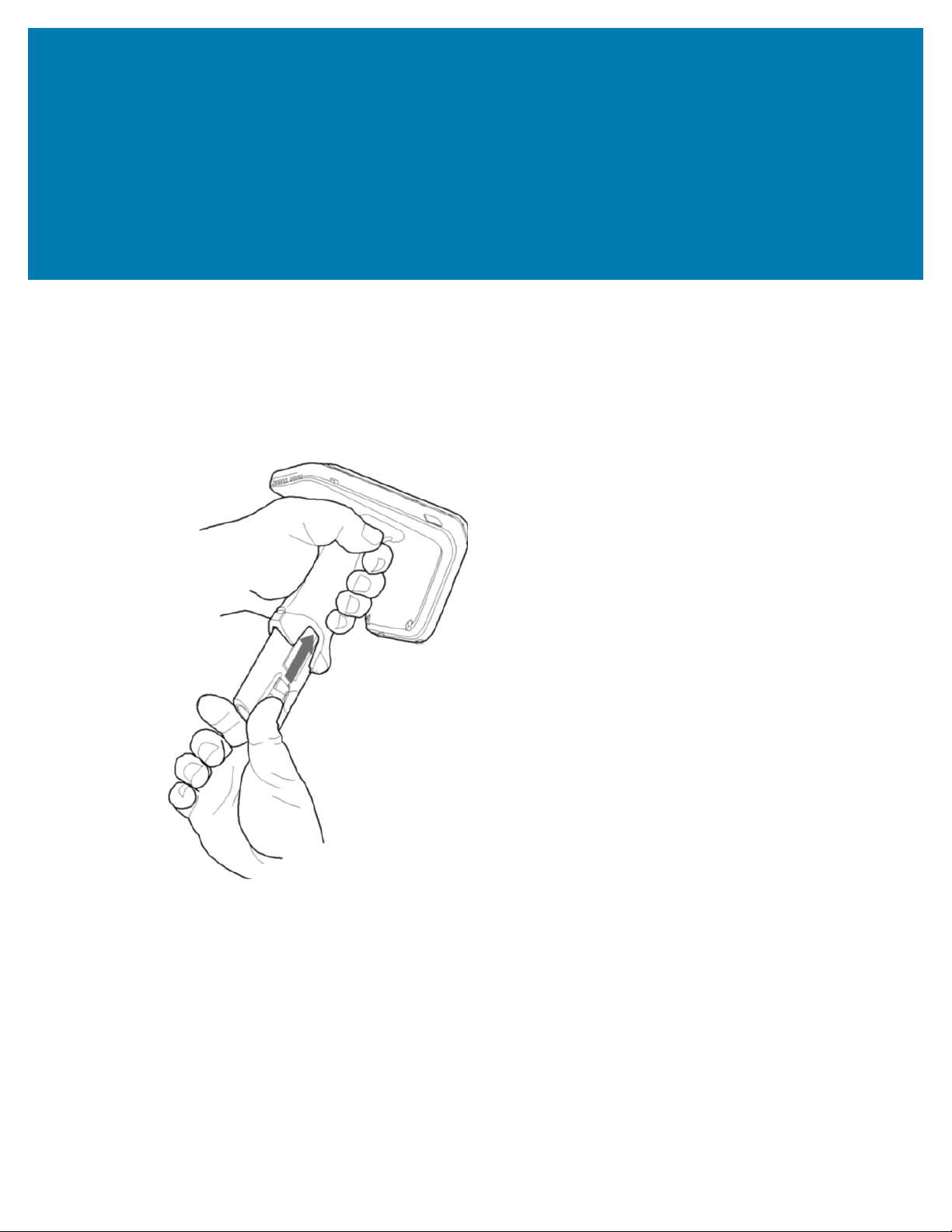
Battery Removal
To remove the battery:
Figure 8Battery Removal
Battery Replacement
1. Pinch the clips on the battery to unlock.
2. Slide downwards to remove the battery from the device.
15
Page 16

Pairing the Sled with a Mobile Computer
Pairing the Sled with a Mobile Computer
Pair the sled with a mobile computer by connecting directly with the communication port, scanning the
barcode on the device, or by using the NFC feature on the RFD4031 to activate NFC Bluetooth pairing and
facilitate Bluetooth communication between the sled and the mobile computer.
• To connect via scan, scan the code on the sled using the mobile computer to obtain the Bluetooth MAC
address to pair the device to the sled.
Figure 9Scan Bluetooth MAC Address
• To connect via NFC, align the NFC area behind the handle of the sled with the NFC area on the back of
the mobile computer to pair.
16
Page 17

Pairing the Sled with a Mobile Computer
Figure 10Scan NFC Area to Pair Device
Once the sled has paired with a mobile computer, the sled recognizes the device going forward and
automatically connects using the 123RFID Mobile or 123RFID Desktop Reader Discovery feature.
17
Page 18

Using theRubber Locking
Foot
Using theRubber Locking Foot
The RFD4031 comes with a standard rubber foot on the bottom of the sled.An optional locking foot that is
used in place of the standard locking foot and secures the battery of the sled is available as a purchasable
accessory.For a full list of accessories that can be used with the RFD4031 RFID Premium sled, refer to the
product specific Technical Accessory Guide available at: zebra.com/support.
Figure 11Rubber Locking Foot
1 Rubber Locking Foot
18
Page 19

Charging
Charging
Before using the RFD4031 for the first time, fully charge the battery by placing it in the charging cradle until
the LED Power/Charging Indicator turns solid green. The RFD40 RFID sled and mobile computer may be
charged in the charging cradle individually or attached together.
When an RFD4031 RFID sled is removed from a charging cradle, it is automatically powered on. If a reader
is not used for a duration of thirty minutes, the reader enters Off mode.
NOTE: The cradle does not charge the device if the battery is completely deplete
Figure 12Single-SlotCharging Cradle
NOTE: The cradle does not charge the device if the battery is completely depleted.
19
Page 20

UI Indicators
UI Indicators
The RFD4031 RFID Premium sled presents multiple forms of feedback to inform the user of various device
states. The sled provides LED definitions for decode and battery status as well as beeper indications to
indicate battery charge progress. The trigger on the device is capable of initiating a bootloader recovery
and carrying out various programmable tasks.
LED Definitions
The sled provides user feedback in the form of LED indications for decode, battery, Bluetooth, and Wi-Fi
states.
Decode LED Definitions
The following table outlines the context in which decode LED feedback is provided and the indication that
is presented for a given device state.
NOTE: The LED indicators on the RFD4031 RFID Premium sled differ from the LED indicators on
the mobile computer being used with the sled.
Table 2RFD4031 Decode LED Indicators
Condition Indication
Good Scan Green
Scan Error Red
RFID Rag Read Indicator Enabled Green
Read Error Red
Battery LED Definitions
The following table outlines the context in which battery LED feedback is provided and the indication that
is presented for a given device state.
Table 3RFD4031 Battery LED Definitions While Charging
Conditions Indications
Pre-charging Amber (Fast, Fast, Slow)
Charging Amber (Blinking)
Fully Charged Green (Stays On)
20
Page 21

UI Indicators
Table 3RFD4031 Battery LED Definitions While Charging (Continued)
Conditions Indications
Charging Error Amber (Fast Blinking)
Bluetooth LED Definitions
The following table outlines the context in which Bluetooth LED feedback is provided and the indication
that is presented for a given device state.
Table 4RFD4031 Bluetooth LED Definitions
Condition Indication
Looking to Pair Amber (Blinking)
Pairing Blue (Stays On)
Paired/Connected Green (Stays On)
Error Red (Stays On)
Wi-Fi LED Definitions
The following table outlines the context in which Wi-Fi LED feedback is provided and the indication that is
presented for a given device state.
Table 5RFD4031 Wi-Fi LED Definitions
Connecting Green (Blinking)
Connected Green (Stays On)
Transmission Error/Out of Range Red (Stays On)
Beeper Indications
The sled provides user feedback in the form of beeper tones for decode, battery, Bluetooth, and Wi-Fi
states.
Decode Beeper Indications
The following table outlines the context in which beeper feedback is provided and the indication that is
presented for a specific decode event.
Table 6RFD4031 RFID Decode Beeper Indications
Condition Indication
Condition Tone
Good Decode Short high tone
Decode Transmission Error No beep
Good RFID Decode Short medium tone
RFID Error No beep
21
Page 22

UI Indicators
Table 6RFD4031 RFID Decode Beeper Indications(Continued)
Condition Tone
Error Message (Other) No beep
Sled Memory Full (Batch Mode) Long tones for 5 seconds
Battery Beeper Indications
The following table outlines the context in which decode LED feedback is provided and the indication that
is presented for a given device state.
Table 7RFD4031 RFID Battery Beeper Indications
Condition Tone
Low Battery (20%) Medium-length tones
Lower Battery (10%) Short tones - repeat
Suspend High/Medium/Low
Charging Short tone when the charger is connected.
Fully Charged One beep
Charging Error Three beeps (single occurrence)
Power On Low/Medium/High beep
Bluetooth Beeper Indications
The following table outlines the context in which beeper feedback is provided and the indication that is
presented for a specific Bluetooth state.
Table 8RFD4031 Bluetooth Beeper Indications
Condition Tone
On/Not Connected No beep
On/Pairing in Process No beep
On/Connected Short/Low/High
Out of Range Short/High/Low
Pairing Error No beep
Off No beep
Wi-Fi Beeper Indications
The following table outlines the context in which beeper feedback is provided and the indication that is
presented for specific Wi-Fi states.
Table 9RFD4031 Wi-Fi Beeper Indications
Condition Tone
On/Not Connected No beep
22
Page 23

UI Indicators
Table 9RFD4031 Wi-Fi Beeper Indications(Continued)
Condition Tone
On/Pairing in Process No beep
On/Connected Short/Low/High
Out of Range Short/High/Low
Pairing Error No beep
Off No beep
23
Page 24

Trigger Modes
Trigger Modes
The follow table outlines the supported trigger functions of the RFD4031.
NOTE: By default, the device assumes the upper trigger as the RFID decode trigger and the
lower trigger as the mobile computer decode trigger.
Table 10Trigger Modes
Condition Upper Trigger Lower Trigger Both Triggers Description
RFID Start/Stop X - - User
Programmable
Barcode Start/
Stop
Start Bootloader
Recovery
Configurable/
Signal Intent to
Mobile Device
- X - User
Programmable
- X - Press and hold
the lower trigger
for five seconds
while inserting the
battery.
- - X Feature support is
determined by the
mobile computer
being used with
the device.
24
Page 25

www.zebra.com
 Loading...