

Page 1

RFD40
RFID Standard Sled
Product Reference Guide
MN-004189-01EN
Page 2

ZEBRA and the stylized Zebra head are trademarks of Zebra Technologies Corporation, registered in
many jurisdictions worldwide. All other trademarks are the property of their respective owners.
© 2021 Zebra Technologies Corporation and/or its affiliates. All rights reserved.
Information in this document is subject to change without notice. The software described in this document
is furnished under a license agreement or nondisclosure agreement. The software may be used or copied
only in accordance with the terms of those agreements.
For further information regarding legal and proprietary statements, please go to:
SOFTWARE:zebra.com/linkoslegal
COPYRIGHTS:zebra.com/copyright
WARRANTY:zebra.com/warranty
END USER LICENSE AGREEMENT: zebra.com/eula
Terms of Use
Proprietary Statement
This manual contains proprietary information of Zebra Technologies Corporation and its subsidiaries
(“Zebra Technologies”). It is intended solely for the information and use of parties operating and
maintaining the equipment described herein. Such proprietary information may not be used, reproduced,
or disclosed to any other parties for any other purpose without the express, written permission of Zebra
Technologies.
Product Improvements
Continuous improvement of products is a policy of Zebra Technologies. All specifications and designs are
subject to change without notice.
Liability Disclaimer
Zebra Technologies takes steps to ensure that its published Engineering specifications and manuals are
correct; however, errors do occur. Zebra Technologies reserves the right to correct any such errors and
disclaims liability resulting therefrom.
Limitation of Liability
In no event shall Zebra Technologies or anyone else involved in the creation, production, or delivery of the
accompanying product (including hardware and software) be liable for any damages whatsoever
(including, without limitation, consequential damages including loss of business profits, business
interruption, or loss of business information) arising out of the use of, the results of use of, or inability to
use such product, even if Zebra Technologies has been advised of the possibility of such damages. Some
jurisdictions do not allow the exclusion or limitation of incidental or consequential damages, so the above
limitation or exclusion may not apply to you.
2
Page 3

Contents
Getting Started
Unpacking ............................................................................................................................. 6
Setting up the RFD40 RFID Standard Sled .......................................................................... 6
Features ................................................................................................................................ 7
Adaptor Installation ............................................................................................................... 8
Installing the Mobile Computer into the Sled ...................................................................... 9
Removing the Mobile Computer from the Sled ................................................................... 9
Sled Battery Replacement .................................................................................................. 10
Battery Installation ............................................................................................................ 10
Battery Removal ............................................................................................................... 10
Charging ............................................................................................................................. 11
UI Indicators ........................................................................................................................ 12
Decode LED Definitions .................................................................................................... 12
Battery LED Definitions ..................................................................................................... 12
Battery Beeper Indications ................................................................................................ 12
Trigger Modes ............................................................................................................................... 13
123RFID Mobile
Requirements ...................................................................................................................... 14
Installing 123RFID Mobile ................................................................................................... 14
Using 123RFID Mobile ........................................................................................................ 14
Readers List ...................................................................................................................... 15
Rapid Read ....................................................................................................................... 18
Locate Tag ........................................................................................................................ 21
Settings ............................................................................................................................. 31
RFID Settings ................................................................................................................... 33
Application Settings .......................................................................................................... 43
123RFID Desktop Application
123RFID Desktop Features ................................................................................................ 44
Connect ............................................................................................................................... 45
Read .................................................................................................................................... 46
Reader Configuration .......................................................................................................... 47
Reader Name ................................................................................................................... 48
3
Page 4

Contents
General Parameter Settings ............................................................................................. 48
Region Configuration ........................................................................................................ 49
Antenna Configuration ...................................................................................................... 50
Trigger Configuration ........................................................................................................ 51
Pre-Filter Configuration ..................................................................................................... 52
Advanced Configuration Settings ...................................................................................... 53
Save and Print Configuration ............................................................................................ 54
Firmware Management ....................................................................................................... 55
Maintenance and Technical Specifications
Maintenance ........................................................................................................................ 57
Known Harmful Ingredients ............................................................................................... 57
Approved Cleaners ........................................................................................................... 58
Cleaning the Sled ............................................................................................................. 58
Technical Specifications ...................................................................................................... 59
Troubleshooting
Troubleshooting .................................................................................................................. 60
4
Page 5

About This Guide
The table below describes the configuration of the RFD40 RFID Standard sled.
Table 1 RFD40 RFID Standard Sled Configurations
SKU Description
RFD4030 RFD40, Standard, Standard Range Circular Polarized Antenna, UHF RFID Only,
Gun, No Imager, 7000mAh Battery, Midnight Black
Service Information
If you have a problem using the equipment, contact your facility's technical or systems support. If there is a
problem with the equipment, they will contact the Zebra Global Customer Support Center at:
zebra.com/support.
When contacting Zebra support, please have the following information available:
• Serial number of the unit
• Model number or product name
• Software type and version number
Zebra responds to calls by e-mail, telephone or fax within the time limits set forth in support agreements.
If your problem cannot be solved by Zebra support, you may need to return your equipment for servicing
and will be given specific directions. Zebra is not responsible for any damages incurred during shipment if
the approved shipping container is not used. Shipping the units improperly can possibly void the warranty.
If you purchased your business product from a Zebra business partner, contact that business partner for
support.
5
Page 6

Getting Started
Unpacking
This chapter provides information on RFD40 RFID Standard sled parts, battery installation, mobile device
attachment, LED indications, and charging. Carefully remove all protective material from the RFD40 RFID
Standard sled and save the shipping container for later storage and shipping.
Verify the following items are in the box:
• RFD40 RFID Standard sled
• Battery
• Lanyard
• Quick Start Guide
Inspect the equipment for damage. If any equipment is missing or damaged, contact the Zebra Support
Center immediately.
For a full list of accessories that can be used with the RFD40 RFID Standard sled, refer to the product
specific Technical Accessory Guide available at: zebra.com/support.
Setting up the RFD40 RFID Standard Sled
The RFD40 UHF RFID Standard sled provides RAIN Radio Frequency Identification (RFID) tag reading,
writing, and locating capability to supported Zebra mobile computers.
To use the sled for the first time with a mobile computer:
1. Insert the battery into the sled
2. Charge the sled in the charging cradle, charging cup, or by USB-C cable.
3. Replace the standard cover that comes with the sled with the adaptor that is specific to the mobile
computer being used with the sled.
4. Place the mobile computer into the adaptor headfirst.
5. Attach the mobile computer on the sled.
6. Set the region using 123RFID Desktop or 123RFID Mobile.
For the latest versions of guides and software, go to: zebra.com/support.
For detailed information, refer to the Product Reference Guide at: zebra.com/support.
6
Page 7

Features
The RFD40 RFID Standard sled adds a RFID gun-style handle with a scanning trigger to the mobile
computer or Windows PC. Used for all RFID operations, the sled increases comfort when using the mobile
computer in scan-intensive applications for extended periods of time.
Figure 1 RFD40 RFID Standard Sled Features
1
2
3
6
4
6
7
5
8
9
10
1 Adaptor (Sold Separately)
2 Coin Screws (4)
3 Adaptor Label
4
eConnex
TM
Communication Port
5 Battery Status LED
6 Decode LED
7 Tri-Function Trigger
8 Charging Contact and USB-C Port
9 Tethering Point for Handstrap
10 Rubber Foot
7
Page 8

Adaptor Installation
To install the adaptor,
1. Remove the cover by pulling up on the lip.
2. Secure the adaptor onto the sled by fastening the four coin screws into the sled.
Figure 2 Adapter Installation
8
Page 9

Installing the Mobile Computer into the Sled
To secure the mobile computer to the RFD40 Standard RFID sled, place the top of the device fully forward
into the sled adaptor and push down on the bottom of the mobile computer.
NOTE: Depending on the mobile computer being used with the sled, the mobile computer may be
inserted into the adaptor tail-end first.
NOTE: While installing the mobile computer into the adaptor, use caution and do not to collide with the
eConnex
TM
communication port pins on the RFD40.
Removing the Mobile Computer from the Sled
To remove the mobile computer from the RFD40 Standard RFID sled, firmly hold the sled handle, and lift
the device off of the sled base.
9
Page 10

Sled Battery Replacement
Battery Installation
To install the battery:
1. Align the battery with the notch facing the back of the device.
2. Slide the battery into the handle of the device.
3. Snap the battery into place.
Battery Removal
To remove the battery, pinch the clips to unlock the battery and slide downwards to release.
10
Page 11

Charging
Before using the RFD40 for the first time, fully charge the battery by placing it in the charging cradle until
the LED Power/Charging Indicator turns solid green. The RFD40 RFID sled and mobile computer may be
charged in the charging cradle individually or attached together.
When an RFD40 RFID sled is removed from a charging cradle, it is automatically powered on. If a reader
is not used for a duration of 30 minutes, the reader enters low power mode.
Figure 3
Single Slot Charging Cradle
11
Page 12

UI Indicators
The RFD40 RFID Standard sled presents multiple modalities to inform the user of various device states.
The sled provides LED definitions for decode and battery status as well as beeper indications to indicate
the charge progress of the battery. The trigger on the sled is capable of carrying out various programmable
tasks to decode and initiate a bootloader recovery.
Decode LED Definitions
Table 2 RFD40 RFID Standard Sled Decode LED Indications
Scan LED Status
Good Scan Green
Scan Error Red
RFID Tag Read Indicator Enabled Green
Read Error Red
Battery LED Definitions
Table 3 RFD40 RFID Standard Sled LED Definitions While Charging
Condition Indication
Pre-charging Amber (Fast, Fast, Slow)
Charging Amber (Blinking)
Fully Charged Green (Stays On)
Charging Error Amber (Fast Blinking)
Firmware Update in Progress Amber-Blinking
Battery Beeper Indications
.
Table 4 RFD40 RFID Standard Sled RFD40 Battery Beeper Indications
Condition Tone
Low Battery (20%) Medium-length tones
Lower Battery (10%) Short tones - repeat
Suspend High/Medium/Low
Charging Short tone when the charger is connected.
Fully Charged One Beep
Charging Error Three Beeps (single occurrence)
Power On Low/Medium/High Beep
12
Page 13

Trigger Modes
NOTE: By default, the device assumes the upper trigger as the RFID decode trigger and the lower
trigger as the mobile computer decode trigger.
Table 5 RFD40 RFID Standard Sled Default Trigger Functions
Condition Upper
Trigger
RFID Start/Stop X - - User Programmable.
Barcode Start/Stop - X - User Programmable.
Start Bootloader Recovery - X - Press and hold the lower trigger for
Configurable/Signal Intent
to Mobile Device
- - X Feature support is determined by the
Lower
Trigger
Both
Triggers
Description
five seconds while inserting the
battery.
mobile computer being used with the
device.
13
Page 14

123RFID Mobile
This section describes the 123RFID Mobile Application which demonstrates the RFD40 RFID Standard
sled’s capability and tag operation functionality.
Requirements
Requirements for the 123RFID Mobile Application for Android are as follows:
• Zebra approved mobile computer compatible with the RFD40 Standard RFID sled.
• 123RFID Mobile Application APK.
Installing 123RFID Mobile
Install the 123RFID Mobile Application on the mobile computer from zebra.com/support or from the Google
Play Store. The procedure to install the software on an Android device is dependent upon the Android
version.
To install the software:
1. Connect the Android device to your computer. It is connected as MTP Device and shown as a drive on
the computer. For information on transferring files using Media Transfer Protocol, refer to the Mobile
Computer Integrator Guide at: zebra.com/support.
2. Navigate to Device Settings > Security and check Unknown Sources to allow installation of applications
from unknown sources.
3. Copy the 123RFID_Mobile_1.0.x.x.apk file to the mobile device.
4. Go to Settings > Security and select Unknown sources.
5. Use the File Manager to locate the 123RFID_Mobile_1.0.x.x.apk file in the folder to which it is copied in
Step 3 and select it.
6. In the pop-up window, select the Android App installer to begin installation.
Using 123RFID Mobile
To use the application for RFID operations:
1. Launch the 123RFID Mobile Application for Android on the mobile device.
2. From the Readers list, tap on the available RFD40 device listed under Available Readers to connect
and view the Rapid Read screen.
3. Tap Settings > RFID > Advanced Reader Options > Antenna. Power Level is set to 27.0 dBm by
default. However, it is shown as 270 dbm because the value used is in units of tens of dBm. Japan units
are set to a different default power level depending on the SKU type.
14
Page 15

Tap the Back button and select Regulatory to set the region in which the device is operating.
4.
Readers List
From the bottom navigation menu tap the Readers icon.
Figure 4 Settings - Readers List Screen
Tap a reader name from the Readers List to establish a session with the selected reader. Tap again to
terminate the session. To obtain additional information about the device, tap Reader Details.
15
Page 16

Figure 5 Reader Details
16
Page 17

Updating the Device Firmware
Update the device firmware by tapping Firmware Update from the menu. Next, select the firmware version
to be loaded onto the device and tap the Update Firmware button.
Figure 6 Firmware Update
17
Page 18

Rapid Read
Tap Rapid Read from the Home or Menu screen.
Figure 7 Rapid Read Screen
The Rapid Read and Inventory screens display the following data (see Inventory on page 19).
• Total Reads
• Unique tag count
• Read time (mm:ss)
• Tag read rate (tags/sec).
The Rapid Read and Inventory screens present two different views of the inventory operation on the
reader. The Start/Stop functionality can be used interchangeably on both screens. For example, when
operation starts on the Rapid Read screen and you navigate to the Inventory screen, the button available
on the Inventory screen is Stop. The same is true when the operation starts on the Inventory screen.
During the rapid read process, you can navigate to the Inventory screen to view tag details along with tag
counts for each tag. The statistics displayed are maintained on the Rapid Read and Inventory screens
regardless of the screen used to start the process.
18
Page 19

Select Start to start the rapid read inventory operation. Select Stop to stop inventory operation.
NOTE The scan trigger on the device can also start and stop the inventory operation. Press the trigger
Progressing to another screen does not halt the operation. However, attempting to make changes or
perform another operation while rapid read is in process results in an error.
Inventory
Once tags begin reading, the tag details populate the inventory screen. To filter the information by type,
tap the Memory Bank dropdown menu and select User, Reserved, TID, or EPC.
Select Inventory from the Home or Menu screen.
Figure 8 Inventory Screen
to start, continue to hold and release to stop.
Memory
Bank
Tag reading is started and stopped on this screen as well as on the Rapid Read screen (see Rapid Read
on page 18). When the process starts, tag information displays on the screen.
19
Page 20

Tap Start to start the rapid read inventory operation. The Start button changes to Stop. Tap Stop to stop
the read inventory operation.
NOTE The scan trigger on the device can also start and stop the inventory operation. Press the trigger
to start, continue to hold and release to stop.
The tag ID selected can be filtered by RFID Settings, Locate, Pre Filters, and Tag Write. After selecting
a tag, tap on the action bar Locate icon to go to the Locate screen. Tags are fully convertible to ASCII
format. ASCII mode may be enabled by selecting Settings > Application Settings.
Figure 9 Tag Data Filters
20
Page 21

Locate Tag
Tap Locate Tag from the Home or Menu screen.
Figure 10 Locate Tag Screen
On this screen, enter the Tag ID in the text area or select a tag from the Inventory screen to pre-populate
the Tag ID to search.
Tap Start to start the locate tag operation and tap Stop to stop. The device trigger can also be used to
start and stop the operation.
NOTE The scan trigger on the device can also start and stop the inventory operation. Press the trigger
The color bar on the display shows the relative distance of the tag.
When the locate tag operation starts, moving to another screen does not stop the operation until Stop is
selected.
Multi Tag
To locate and track multiple tags, select the Add a File icon on the multi-tag panel and select the file
containing the specific tag information from the file manager to bring the file into the application.
to start, continue to hold and release to stop.
21
Page 22

Figure 11 Multi Tag File Upload
22
Page 23

Inventory Screen Features
Table 6 Inventory Screen Features
Item Description
Action Bar
Tags
Search
Power
Management
Content Area
(select a tag)
Content Area
(select a tag)
Tap Memory Bank to select one of the following memory bank options from the
drop-down menu:
• None - Defaults to EPC.
• User - Allows reading user memory bank data when the tag is inventoried.
• Reserved - Allows reading reserved memory bank data when the tag is inventoried.
• TID - Allows reading TID memory bank data when the tag is inventoried.
• EPC - Allows reading EPC memory bank data when the tag is inventoried.
When the next inventory operation starts, the details from the selected memory bank
displays. This menu is inactive if there is an ongoing operation on the connected
reader.
• Default Display - None.
Tap the Search icon and enter a tag ID. Tags that match the entry display in the content
area.
Icon indicates if Dynamic Power is on. See Power Management on page 41.
Tap the Power Management icon to open the Battery Status screen.
Tapping a Tag ID highlights the tag. The highlighted Tag ID is populated on the Tag
Location text area as well as the Tag Pattern area in the Access Control screen. Tap
Start to start searching for the tag. See Tag List Match Mode Operation on page 24 for
more details. From this screen, return to the Menu or go to the Home screen and select
Locate Tag.
The tags displayed in this area are based on the option selected from the memory bank.
Tap the tag ID to expand details about the tag. Tap the tag ID again to collapse details.
Example Default Tag Display:
Tag IDTag Count
AD99 15404190725965400404
Example Expanded Tag Display:
Note: Expanded tag detail can only display when the inventory operation is stopped.
Memory bank data is shown only when inventory is complete.
Tag IDTag Count
AD99 15404190725965400404
EPC MEMORY3000
RSSI
-50
Phase
1800
USER
1122334455667788AABBCCDDEEFF
1122334455667788AABBCCDDEEFF
1122334455667788AABBCCDDEEFF
23
Page 24

Tag List Match Mode Operation
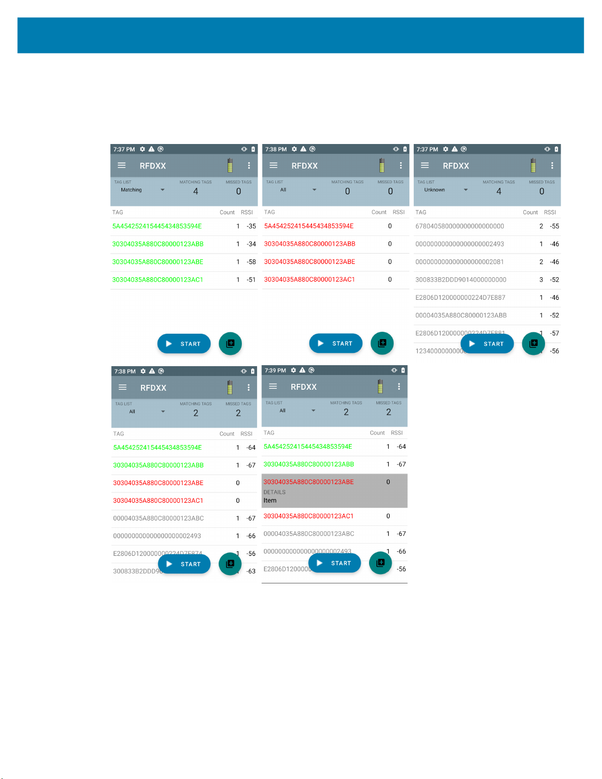
When Tag List Match Mode is checked on the Application screen (Application Settings on page 43), the
application identifies tags from a given set of tags in csv tag list format (comma separated values file). The
contents of the csv file display on the Inventory screen. By default, the application displays friendly names
from csv files.
Before the inventory starts, the count is zero. The tag list can be sorted using the drop-down menu
choices. Select an option to display the type of tags to show when the inventory starts.
All: Sample 4 Inventory List: Tag List Enabled; All Tag Option Selected on page 28
Matching: See Sample 1 Inventory List: Tag List Enabled; Matching Tag Option Selected on page 24.
Missing: See Sample 2 Inventory List: Tag List Enabled; Missed Tag Option Selected on page 26.
Unknown: Sample 3 Inventory List: Tag List Enabled; Unknown Tag Option Selected on page 27
Sample Contents of Taglist.csv File
The csv file should contain only alphanumeric characters in the tag column. If there are any special
characters, the row is discarded.
The Taglist.csv file must be located inside the rfid folder which must be manually created at the Android
device root directory.
NOTE The folder name must be all lower case (for example, rfid and not RFID).
Figure 12 Taglist.csv File Contents
Sample 1 Inventory List: Tag List Enabled; Matching Tag Option Selected
When inventory starts, the application only displays the tag reads that match the tags in the taglist.csv file.
Matching tags display in green. Select any tag read to show the matching tag details in the csv file.
24
Page 25

Figure 13 Matching Taglist.csv File Contents
25
Page 26

Sample 2 Inventory List: Tag List Enabled; Missed Tag Option Selected
When inventory starts, the application only displays the tag reads that are missed and included in the
taglist.csv file. Missed tags display in red. Select any tag to show the missed tag details in the csv file.
Figure 14 Missed Taglist.csv File Contents
26
Page 27

Sample 3 Inventory List: Tag List Enabled; Unknown Tag Option Selected
When inventory starts, the application only displays tags that were read but not included in the taglist.csv
file. Unknown tags display in gray. Select any tag to show the unknown tag details.
Figure 15 Unknown Tags
27
Page 28

Sample 4 Inventory List: Tag List Enabled; All Tag Option Selected
When inventory starts, the application displays the tags for all of the options:
• Tag reads that match the tags in the taglist.csv file. Matching tags display in green. Select any tag read
to show the matching tag details in the csv file.
• Tag reads that are missed and included in the taglist.csv file. Missed tags display in red. Select any tag
to show the missed tag details in the csv file.
• Tags that were read but not included in the taglist.csv file. Unknown tags display in gray. Select any tag
to show the unknown tag details.
Figure 16 All Tags
28
Page 29
Sample 5 Tag List Matching Selected; Show Friendly Not Names Selected
When inventory starts, the application displays the tags for selected options from All, Matching, Missing, or
Unknown. Application shows friendly names (i.e., Tag details instead of EPC) on screen.
Figure 17 Show Friendly Names Enabled
Sample 6 Exporting Data - Tag List Matching Selected
The Application Settings screen on page 43 has the option to Export Data. If the option is checked, data is
exported when the inventory stops. The tag content area is exportable to a file. For example, when
Matching is selected from the menu to display only matching tags in the tag content area, the matching
data can be exported to a file. The exported csv file includes the matching, missing, and unknown tag
count shown in Figure 18.
29
Page 30

Figure 18 Exported File Content
30
Page 31

Unique Tag Reporting
When Unique Tag Reporting is enabled on the Tag Reporting screen on page 39, the reader reports only
unique tags based on the options below.
• When the Matching option is selected (see Sample 1 Inventory List: Tag List Enabled; Matching Tag
Option Selected on page 24) the tag count cannot be greater than one because the unique tags are
only reported one time.
• When the Matching option is not selected, the list displays unique and total reads. The tag count
cannot be greater than one because the unique tags are only reported one time.
Settings
To access the Settings of the device, tap the Settings Icon from the bottom navigation bar. Settings is split
up into General Settings to configure settings on the device, RFID Settings to configure specific reader and
antenna settings, and Application settings to make changes to the 123RFID Mobile application settings.
General Settings
Figure 19 Settings Screen
Table 7 General Settings Screen Options
Settings Option Description
Firmware Update Update the firmware on the reader.
Factory Reset Reset the settings on the reader to Factory Defaults.
Enable Logging Enable the logging of tag reads.
Device Info
Share File Share a file with a paired device.
Trigger Mapping
View information such as friendly name, serial number, model, and
RFID/scan settings.
Designate the Upper Trigger for RFID decode and the Lower
Trigger for Host Scan or the Upper Trigger for Host Scan and the
Lower Trigger for RFID decode.
31
Page 32

Updating the Device Firmware
Update the device firmware by tapping Firmware Update from the menu. Next, select the firmware version
to be loaded onto the device and tap the Update Firmware button.
Figure 20 Firmware Update
32
Page 33

RFID Settings
Figure 21 Settings Screen
Table 8
RFID Settings Option Description
Profiles Displays Fastest Read, Cycle Count, Dense Readers, Optimal
Advanced Reader Settings Antenna, Singulation, Control, Start/Stop Triggers, Tag Reporting, Power
Regulatory Allows region and channel selections.
Battery Displays the device battery status.
Beeper Use to turn the beeper on/off, and set volume.
LED Enables/Disables the device tag read LED indicator.
Battery, Balanced Performance, User Defined and Reader Defined
profiles.
Management and Save Configuration
Profiles
To display the list of profiles, tap Settings > Profile.
• The currently selected profile is highlighted in orange.
• Tap profile item to expand the profile and view applicable configurations.
• Profiles can be selected or disabled by using the slider switch to the right of the profile name.
NOTE If Power Level, Link Profile, Session, or Dynamic Power are modified from each respective
screen, then the currently selected profile changes to User Defined profile and profile item
values are modified with same values.
Profile setting options are as follows:
• Fastest Read - Read as many tags as fast as possible.
• Cycle Count - Read as many unique tags as possible.
• Dense Readers - Use when there are multiple readers within close proximity.
• Optimal Battery - Provides best battery life.
• Balanced Performance - Maintains balance between performance and battery life.
33
Page 34

• User Defined - Custom profile used for custom requirements.
• Reader Defined - Maintains reader configurations.
Figure 22 Profiles Settings
34
Page 35

Advanced Reader Settings
Antenna
To access the Antenna screen, go to: Settings > Advanced Reader Options > Antenna. The Antenna
screen displays the following:
• Power Level - Displays the current selection and a text box for available power levels (as reported by
the device). The default setting is 27.0 dBm (shown as 270; the value displayed is in units of tens of
dBm). Japan units are set to a different default power level depending on the SKU type.
The minimum power level when DPO is enabled is 3.1 dBm. When DPO is disabled, the minimum
power level is 0 dBm.
• Link Profile - Displays the current selection and includes a drop-down list of available link profiles
(reported by the device).
Link Profile display format is as follows: Return link bit data rate in bis per second (e.g., 60000 -> 60
Kbs); Miller Value (e.g., MV_4 -> Miller 4); thus profile name M4 240K (240K becomes BLF) modulation
type (PR ASK is the only one supported).
• PIE value has no units and is either 1500 and 2000 minimum.
• Tari applicable Tari value in thousands of micro seconds (e.g., 6250 -> 6.25 microseconds).
35
Page 36

Figure 23 Antenna Screen
NOTE The Power Level and Link Profile are blank when there is no connection to the reader.
Singulation Control
To access Singulation Control, go to: Settings > Advanced Reader Options > Singulation Control.
View or configure the singulation control settings for each antenna.
• Session - The drop-down list includes the available session options (S0, S1, S2, S3).
• Tag Population - A numeric value of the estimated number of tags in the Field of View (FOV). Values
shown are 30, 100, 200, 300, 400, 500, 600.
• Inventory State - State A, State B, AB Flip.
• SL flag - ALL, DEASSERTED, ASSERTED.
36
Page 37

Figure 24 Singulation Control Screen
Start and Stop Triggers
To access the Start and Stop Triggers screen, go to: Settings > Advanced Reader Options > Start\Stop
Triggers.
The Start Trigger Periodic displays the Period input box (in milliseconds).
The Stop Trigger Duration, Tag Observation and N attempts display numeric value input boxes. All
time entries are in milliseconds.
All the required details for saving triggers to the reader must be entered or the application does not save
the trigger settings to the reader.
37
Page 38

Figure 25 Start and Stop Triggers Screen
Required input for Start/Stop Trigger settings are as follows:
• Start Trigger
• Immediate (default)
• Hand-held - Select either the Trigger Pressed or Trigger Released check box.
• Periodic - Enter the period of time in milliseconds.
• Stop Trigger
• Immediate (default)
• Hand-held - Select either the Trigger Pressed or Trigger Released check box along with
Timeout in milliseconds.
• Duration - Enter duration in milliseconds.
• Tag Observation - Enter the tag count along with timeout in milliseconds.
• N Attempts - Enter the number of attempts along with timeout in milliseconds.
If the start trigger type is set to Hand-held trigger (pressed or released), the application sets the repeat for
the operation to ensure the use case if repeated operations can be demonstrated.
If any trigger is defined as Hand-held, the application does not act on immediate trigger type for a
Hand-held trigger action.
Tag Reporting
To access Tag Reporting, go to: Settings > Advanced Reader Options > Tag Reporting.
38
Page 39

Figure 26 Tag Reporting Screen
Table 9 Tag Reporting Screen Options
Option Description
PC Select to allow reporting the PC as part of the Tag Data.
RSSI Selection indicates whether or not the RSSI (Received Signal Strength
Indication) is reported as part of the Tag Data.
Phase Select to indicate whether or not the Phase is reported as part of the Tag
Data.
Channel Index Select to indicate whether or not the Regulatory Channel Index is reported
as part of the Tag Data.
Tag Seen Count Select to indicate whether or not the Tag Seen Count is reported as part of
the Tag Data.
Report Unique Tags When this option is enabled, the reader reports only unique tag reads.The
Unique Tag reporting feature can be enabled when using Tag List Match
mode.
Power Management
This screen provides an option to enable Dynamic Power Optimization (DPO) in the reader. Enabling
DPO enhances battery life during inventory operations.
NOTE DPO is enabled by default. It is not necessary to disable DPO when executing access operations or using
filters because DPO is automatically disabled and when the operation is complete, it is automatically
enabled.
If Dynamic Power is On, a green battery icon appears in the title bar of the application. Tapping on this
opens the Battery Status screen.
39
Page 40

To access Power Management, go to: Settings > Advanced Reader Options > Power Management.
Figure 27 Power Management Screen
Save Configuration
To access Save Configuration, go to: Settings > Advanced Reader Options > Save Configuration. This
screen is used to save the settings and displays the current settings on the device.
The settings are saved on the device until a reset to factory defaults is performed on the unit (see Settings
on page 31).
The Tag Pattern area is automatically filled in when a tag is selected in the Inventory screen.
40
Page 41

Figure 28 Save Configuration Screen
Access Control
Figure 29 Access Control Screens - Read/Write, Lock, Kill
The Tag Pattern area is automatically filled in when a tag is selected in the Inventory screen.
Read/Write
The Read/Write access operation is simplified with offset and length fields are hidden. The user can tap
the more/advanced options icon to see offset and length fields. Tap the icon again to hide the advanced
options.
41
Page 42

Memory Bank options now have extended menu options to choose directly interested area of memory
bank. This avoids typing of offset and length etc.
Read/Write
Read/Write options are:
• Tag ID and Password values are in hex. Tag ID is edited.
• Memory Bank options - EPC, TID, USER, PC and CRC, Access Password, Kill Password.
• Offset and Length values are in 16-bit words. This is only available after tapping the Advance
Options icon. To toggle visibility, tap Advanced Options again.
• Access operation screen maintains edited tag ID.
Lock
Lock privilege options are as follows:
• Read and Write
• Permanent Lock
• Permanent Unlock
• Unlock
Kill
Permanently renders the tag unusable. A Kill Password must be provided.
42
Page 43

Application Settings
From the Settings screen, select Application
Figure 30 Settings - Application Screen
Table 10 Application Settings
.
Settings Option Description
Auto Reconnect Reader When checked, the device connects to the RFID service which
manages the connection to the reader.
Reader Connection
Notification
Reader Battery Status
Notification
Export Data When checked, the application writes the inventoried RFID data
Tag List Match Mode Check to enable matching mode.
Show Friendly Names Check to show the tag's friendly names instead of EPC ID. Show
ASCII Mode Displays tag ID in ASCII format. If the full tag ID or memory bank
When checked, the application notifies the user when the reader
is connected or disconnected.
When checked, the application notifies the user when the battery
has reached specific critical states.
to a file when the inventory operation stops. On Android platforms
the file is saved in a fixed directory. Check the files in file
browsing in the Inventory directory (Sdcard/inventory/<files>).
The files may be copied to a PC.
friendly names is only available when Tag List Match Mode is
enabled.
data is convertible to ASCII format, then the application only
shows the same. Inventory, Locate, Access, and Pre Filters show
ASCII mode represented data in respective sections.
43
Page 44

123RFID Desktop Application
123RFID Desktop is a setup and optimization tool for the RFD40 Standard RFID Sled. This section
describes the application and its features.
123RFID Desktop Features
• Connect - allows users to search for readers on the local subnet or USB port.
• Read - allows users to start an inventory, view summary metrics on tag reads and sort, filter and export
tag data. Select an antenna and set the power level to begin building an inventory.
• Configure - allows users to configure reader and antenna settings. Settings can be saved to a file or as
a printed report.
• Firmware - allows users to update the firmware on up to five devices.
44
Page 45

Connect
Users can locate readers on the local subnet or via USB port by clicking the Find Readers button or by
entering the IP, hostname or COM port and clicking Connect.
Figure 31 Adapter Installation
To discover readers on the network view the Available Readers section of the application and click
Connect on one of the associated rows to connect to the specified reader.
Figure 32 Reader Discovery
45
Page 46

Read
The read feature allows users to start an inventory. Users can view summary metrics on tag reads by
reader, sort, filter and export tag data to a file. Select antenna and set power level to do inventory.
Figure 33 Data View
Click the Start button to start reading tags and recording an inventory.
Figure 34 Inventory View
To download the inventory data for offline view:
1. Click the Export button to export tag data to excel.
46
Page 47

a. Export Summary – Save a snapshot of all the tag reads displayed on Read screen, in excel.
b. Export History – Save timeline data for tags read, in excel.
To edit access operation information on a specific tag, select and double click on the associated tag row.
Figure 35 Access Operations
To access specific tag location details, click on the Tag Locate tab.
Figure 36 Tag Locate
47
Page 48

Reader Configuration
The Reader Configuration wizard configures the reader and antenna settings and saves them instantly.
Users can also save settings to a file on the PC or print a report.
1. Click Edit Configuration on Reader to edit reader’s settings and use the wizard to do the following:
• Assign names to reader and its connected antennas.
• Set antenna settings or reset them to factory defaults.
• Change reader’s region configuration.
• Create rules for your GPIO (General Purpose Input/Output) accessories on when to trigger
inventory and output results.
• Save/print configurations to a file.
2. Click Load a Saved Configuration File to Reader to load a saved configuration file from the PC to
another connected reader.
Figure 37 Configuration Settings
48
Page 49

Reader Name
Add a description or name the reader by filling out the form fields on the name screen.
Figure 38 Name Screen
General Parameter Settings
Configurable general parameter settings include trigger mode (RFID or barcode), beeper volume
(high/medium/low/quiet), dynamic power (enable or disable) and unique tag reporting (enable or disable).
Figure 39 General Settings
49
Page 50

Region Configuration
To set up the region in which the reader will be used, select the Region of Operation from the drop down
menu. Next, select the appropriate channels by clicking the associated check boxes.
Ensure that the reader is configured for the correct region that it will be used in. Configuring the device for
a different region is illegal.
Figure 40 Region Configuration
50
Page 51

Antenna Configuration
Configure the name and color of the antenna, enable or disable Select for Reads, adjust the power (dBm),
and enable different RF modes using Antenna Port Settings.
Figure 41 Antenna Port Configuration
51
Page 52

Trigger Configuration
Triggers that indicate to the device to start reading tags can be configured to occur during specific events
such as what Start is pressed, when the handheld trigger is pressed, or after a specified duration (ms).
Triggers that indicate to the device to stop reading tags can be configured to occur after specific events
such as when Stop is pressed, a specified amount of tag reads, a specified duration of time (ms), a specific
number of inventory rounds complete, or when the handheld trigger is released.
Figure 42 Trigger Settings Configuration
52
Page 53

Pre-Filter Configuration
Configure pre-filters by first enabling the filter by clicking the checkbox. Next, enter the data into the tag
pattern field, select the target, memory, and action from the associated dropdown menus. Last, enter the
offset into the form field and click Next.
Figure 43 Pre-Filter Configuration
53
Page 54

Advanced Configuration Settings
Enable Editing of Advanced Settings, then choose antenna singulation from the dropdown menu, select
State Aware options, and determine the Tag Population Estimate. Click Sync to save the changes and
complete the configuration workflow.
Figure 44 Advanced Configuration Settings
54
Page 55

Save and Print Configuration
Save the configuration file to the PC, push the antenna settings to the reader, or reset the antenna settings
to factory defaults at the end of the configuration workflow.
Figure 45 Save Configuration
55
Page 56

Firmware Management
To update reader firmware on up to five devices simultaneously, select the devices on the table by clicking
the associated checkbox and click the Update Firmware button.
Figure 46 Select Devices to Update
Next, the Reader Firmware Update window displays. Click Browse to select the firmware version to be
enabled onto the selected device.
Figure 47 Select a Firmware Update
56
Page 57

Once the firmware file is selected, the update starts and the progress bars next to the associated readers
indicate the completion percentage of the update.
Figure 48 Firmware Update Progress
57
Page 58

Maintenance and Technical Specifications
This chapter provides suggested sled maintenance, troubleshooting, and technical specifications.
CAUTION:Always wear eye protection.
Read warning label on compressed air and alcohol product before using.
If you have to use any other solution for medical reasons please contact Zebra for more information.
WARNING: Avoid exposing this product to contact with hot oil or other flammable liquids. If such exposure occurs,
unplug the device and clean the product immediately in accordance with these guidelines.
Maintenance
IMPORTANT Use pre-moistened wipes and do not allow liquid cleaner to pool.
1
Ensure the following items are addressed when using sodium hypochlorite (bleach) based
cleaners:
• For device only. Do not use on cradle.
• Always follow the manufacturer’s recommended instructions: use gloves during application and
remove the residue afterwards with a damp cloth to avoid prolonged skin contact while
handling the device.
• Due to the powerful oxidizing nature of sodium hypochlorite, the metal surfaces, including
electrical contacts on the device, are prone to oxidation (corrosion) when exposed to this
chemical in the liquid form (including wipes) and should be avoided. In the event that these
type of disinfectants come in contact with metal on the device, prompt removal with a
dampened cloth after the cleaning step is critical.
IMPORTANT To avoid damage to the device, use only approved cleaning and disinfecting agents listed below.
The use of non-approved cleaning or disinfecting agents may void the warranty.
Known Harmful Ingredients
The following chemicals are known to damage the plastics on Zebra devices and should not come in contact with
the device:
• Acetone
• Ammonia solutions
• Aqueous or alcoholic alkaline solutions
• Aromatic and chlorinated hydrocarbons
• Benzene
• Carbolic acid
57
Page 59

• Compounds of amines or ammonia
• Ethanolamine
• Ethers
• Ketones
• TB-lysoform
• Toluene
• Trichloroethylene.
Approved Cleaners
• Isopropyl alcohol 70% (including wipes)
• 10% Bleach (Sodium Hypochlorite 0.55%) and 90% Water solution
• 3% Hydrogen Peroxide and 97% Water solution
• Mild dish soap.
Cleaning the Sled
Routinely cleaning the exit window is required. A dirty window may affect scanning accuracy. Do not allow
any abrasive material to touch the window.
To clean the device:
1. Dampen a soft cloth with one of the approved cleaning agents listed above or use pre-moistened
wipes.
2. Gently wipe all surfaces, including the front, back, sides, top and bottom. Never apply liquid directly to
the device. Be careful not to let liquid pool around the device window, trigger, cable connector or any
other area on the device.
3. Be sure to clean the trigger and in between the trigger and the housing (use a cotton-tipped applicator
to reach tight or inaccessible areas).
4. Do not spray water or other cleaning liquids directly into the exit window.
5. Wipe the device exit window with a lens tissue or other material suitable for cleaning optical material
such as eyeglasses.
6. Immediately dry the device window after cleaning with a soft non-abrasive cloth to prevent streaking.
7. Allow the unit to air dry before use.
8. Connectors:
a. Dip the cotton portion of a cotton-tipped applicator in isopropyl alcohol.
b. Rub the cotton portion of the cotton-tipped applicator back-and-forth across the connector on the
Zebra sled at least 3 times. Do not leave any cotton residue on the connector.
c. Use the cotton-tipped applicator dipped in alcohol to remove any grease and dirt near the connector
area.
d. Use a dry cotton tipped applicator and rub the cotton portion of the cotton-tipped applicator
back-and-forth across the connectors at least 3 times. Do not leave any cotton residue on the
connectors.
58
Page 60

Technical Specifications
Table 11 RFD40 RFID Standard Sled Technical Specifications
Item Description
Physical Characteristics
Dimensions Height: 15.6 cm (5.94 in.)
Weight ~19.1 oz./~541 grams (sled with battery)
Power PowerPrecision+ 7000 mAh Li-Ion battery
Frequency Range/
RF Output
User Environment
Operating Temperature -10°C to 50°C (14°F to 122°F)
Storage Temperature -40°C to 70°C (-40°F to 158°F)
Charging Temperature 0°C to 40°C (32°F to 104°F)
Relative Humidity Operating: 5 to 85% non-condensing
Sealing IP54
Drop Specification Multiple 5 ft./1.8 m drops onto concrete
Tumble Specification 500 1/2 meter tumble cycles (1000 drops) at 20°C
Electrostatic Discharge
(ESD)
Width: 8.4 cm (3.3 in.)
Length: 16.6 cm (6.5 in.)
US: 902-928 MHz; 0 - 30 dBm (EIRP)
EU: 865-868 MHz; 0 - 30 dBm (EIRP)
Japan: 916-921 MHz (w LBT); 0 - 30 dBm (EIRP)
± 15 kV air discharge
± 8 kV direct discharge
± 8 kV indirect discharge
59
Page 61

Troubleshooting
Troubleshooting
Table 12 Troubleshooting the RFD40 RFID Standard Sled
Symptom Possible Cause Action
The RFID sled does not
read tags.
RFID sled is attached to
mobile device and it is
not responsive to a RFID
application, even after
the trigger is pressed.
RFID sled is responsive
but cannot read tags.
The RFD40 RFID sled
LED blinks fast amber
when in the cradle.
The RF region
configuration is not set.
Battery is too low and
not able to power the
RFID sled.
Zebra supported mobile
computer is not properly
inserted in the RFID
Sled.
Damaged battery. If the RFD40 RFID sled LED does not blink amber after
Battery is critically low. Place the RFID sled in the charging cradle. The RFID
Charging error. Restart charging by removing the RFID sled from the
Use the 123RFID Desktop or 123RFDID Mobile
application to set the regulatory region or country
operation per the application instructions.
Press the trigger for a couple of seconds to power the
RFID sled On. The RFID sled LED blinks amber when it
is turned On.
(By default, pressing the trigger turns On the RFID sled
if it is in Off mode. However, the RFID sled can be
disabled in which case this step is not necessary.)
Place the RFID sled in the charging cradle. The RFID
sled blinks amber LEDs indicating charging
commenced.
Reinsert the Zebra supported mobile device securely in
the RFID sled and ensure that the USB cable is correctly
inserted.
sitting on charging cradle for a while, request service to
replace battery.
Sled LED blinks amber. The RFID sled can be used
when its LED turns on momentarily amber or green
upon removal from charging cradle.
cradle and inserting it back in the cradle. If issue
persists, request service to replace battery.
60
Page 62

Table 12 Troubleshooting the RFD40 RFID Standard Sled
Symptom Possible Cause Action
RFID sled LED blinks
red, or LED blinks red
alternating with green or
amber while in use (not
while charging).
Zebra supported mobile
computer battery is not
charging.
Battery end of life
indication.
Charging cradle was
unplugged from AC
power.
The Zebra supported
mobile computer is not
fully seated in the
cradle.
Request service to replace battery.
Ensure the charging cradle is receiving power.
Remove and re-insert the zebra supported mobile
computer into the cradle, ensuring it is firmly seated in
the charging cradle.
61
Page 63

Page 64

zebra.com
 Loading...