

Zebra MS4717 Integration Manual

MS4717
Fixed Mount Imager
Integration Guide
Draft V1.0
MN-003432-01

Copyright
© 2019 ZIH Corp. and/or its affiliates. All rights reserved. ZEBRA and the stylized Zebra head are trademarks of
ZIH Corp., registered in many jurisdictions worldwide. All other trademarks are the property of their respective
owners.
COPYRIGHTS & TRADEMARKS: For complete copyright and trademark information, go to www.zebra.com/
copyright.
WARRANTY: For complete warranty information, go to www.zebra.com/warranty.
END USER LICENSE AGREEMENT: For complete EULA information, go to www.zebra.com/eula.
Terms of Use
• Proprietary Statement
This manual contains proprietary information of Zebra Technologies Corporation and its subsidiaries
(“Zebra Technologies”). It is intended solely for the information and use of parties operating and
maintaining the equipment described herein. Such proprietary information may not be used, reproduced,
or disclosed to any other parties for any other purpose without the express, written permission of Zebra
Technologies.
• Product Improvements
Continuous improvement of products is a policy of Zebra Technologies. All specifications and designs are
subject to change without notice.
• Liability Disclaimer
Zebra Technologies takes steps to ensure that its published Engineering specifications and manuals are
correct; however, errors do occur. Zebra Technologies reserves the right to correct any such errors and
disclaims liability resulting therefrom.
• Limitation of Liability
In no event shall Zebra Technologies or anyone else involved in the creation, production, or delivery of the
accompanying product (including hardware and software) be liable for any damages whatsoever
(including, without limitation, consequential damages including loss of business profits, business
interruption, or loss of business information) arising out of the use of, the results of use of, or inability to
use such product, even if Zebra Technologies has been advised of the possibility of such damages. Some
jurisdictions do not allow the exclusion or limitation of incidental or consequential damages, so the above
limitation or exclusion may not apply to you.
Revision History
Changes to the original guide are listed below:
Change Date Description
Initial Draft 1/2019 Draft Version 1.0
2

Table of Contents
Copyright ........................................................................................................................................... 2
Terms of Use .................................................................................................................................... 2
Revision History ................................................................................................................................ 2
About This Guide
Introduction ........................................................................................................................................ i
Chapter Descriptions ......................................................................................................................... i
Notational Conventions ..................................................................................................................... ii
Related Documents .......................................................................................................................... ii
Service Information ........................................................................................................................... ii
Getting Started
Introduction ....................................................................................................................................... 3
MS4717 Features ........................................................................................................................ 4
Theory of Operation .......................................................................................................................... 4
MS4717 Block Diagram Descriptions .......................................................................................... 5
MS4717 Decoder/Interface Board ............................................................................................... 5
Power Management .............................................................................................................. 5
123Scan
Introduction ....................................................................................................................................... 6
123Scan ............................................................................................................................................ 6
Communication with 123Scan ..................................................................................................... 7
123Scan Requirements ............................................................................................................... 7
123Scan Information ................................................................................................................... 7
Scanner SDK, Other Software Tools, and Videos ...................................................................... 8
Advanced Data Formatting (ADF) ..................................................................................................... 8
Introduction ....................................................................................................................................... 9
Mounting ........................................................................................................................................... 9
MS4717 Mounting Dimensions ................................................................................................... 9
Connecting the MS4717 ................................................................................................................. 12
USB Host Connection ............................................................................................................... 12
Accessories ..................................................................................................................................... 13
Location and Positioning ................................................................................................................. 13
Window Material ........................................................................................................................ 14
Cell Cast Acrylic (ASTM: PMMA) .............................................................................................. 14
Cell Cast ADC (ASTM: ADC) .................................................................................................... 14
Chemically Tempered Glass ..................................................................................................... 14
Commercially Available Coatings ................................................................................................... 15
Anti-Reflection Coatings ......................................
Polysiloxane Coating ................................................................................................................. 15
A Word About Coatings ............................................................................................................. 15
Embedded Window Angle and Position .................................................................................... 16
Optical Path .................................................................................................................................... 17
Recommended Exit Window Information ........................................................................................ 18
Exit Window Notes .................................................................................................................... 18
Zebra SNAPI Software Developer's Kit ........................................................................................... 19
...................................................................... 15
3

Table of Contents
Scanning
Introduction ..................................................................................................................................... 20
Imaging System .............................................................................................................................. 20
Aiming System .......................................................................................................................... 20
Aiming with MS4717 ................................................................................................................. 20
Aiming Error .............................................................................................................................. 20
Aiming Control ........................................................................................................................... 20
Illumination System ................................................................................................................... 21
Illumination Control ................................................................................................................... 21
Frame Rate Control ................................................................................................................... 21
Supported Symbologies .................................................................................................................. 21
Operating Modes ............................................................................................................................ 22
Specifications
MS4717 Technical Specifications .................................................................................................. 23
Skew, Pitch and Roll ................................................................................................................. 25
Decode Zones ................................................................................................................................. 26
Maintenance and Troubleshooting
Overview ......................................................................................................................................... 27
Maintenance ................................................................................................................................... 27
Troubleshooting .............................................................................................................................. 27
User Preferences
Introduction ..................................................................................................................................... 29
Scanning Sequence Examples ....................................................................................................... 30
Errors While Scanning .................................................................................................................... 30
User Preferences Parameter Defaults ............................................................................................ 30
User Preferences ............................................................................................................................ 32
Default Parameters ................................................................................................................... 32
Parameter Barcode Scanning ................................................................................................... 33
Beep After Good Decode .......................................................................................................... 33
Direct Decode Indicator ............................................................................................................. 34
Beeper Volume ......................................................................................................................... 35
Beeper Tone ............................................................................................................................. 36
Beeper Duration ........................................................................................................................ 37
Suppress Power Up Beeps ....................................................................................................... 37
Low Power Mode ...................................................................................................................... 38
Hands-free Decode Aiming Pattern .......................................................................................... 41
Picklist Mode ................................................................................................................
Continuous Barcode Read ........................................................................................................ 43
Unique Barcode Reporting ........................................................................................................ 43
Decode Session Timeout .......................................................................................................... 44
Hands-free Decode Session Timeout ....................................................................................... 44
Timeout Between Decodes, Same Symbol ............................................................................... 45
Decode Mirror Images (Data Matrix Only) ................................................................................ 46
Mobile Phone/Display Mode ..................................................................................................... 47
PDF Prioritization ...................................................................................................................... 48
............. 42
4

Table of Contents
PDF Prioritization Timeout ........................................................................................................ 49
Presentation Mode Field of View .............................................................................................. 49
Decoding Illumination ................................................................................................................ 50
Add an Enter Key ...................................................................................................................... 50
Transmit Code ID Character ..................................................................................................... 51
Prefix/Suffix Values ................................................................................................................... 52
Scan Data Transmission Format ............................................................................................... 53
FN1 Substitution Values ............................................................................................................ 54
Transmit “No Read” Message ................................................................................................... 55
Unsolicited Heartbeat Interval ................................................................................................... 56
Dump Scanner Parameters ....................................................................................................... 57
Imager Preferences
Introduction ..................................................................................................................................... 58
Scanning Sequence Examples ....................................................................................................... 59
Errors While Scanning .................................................................................................................... 59
Imaging Preferences Parameter Defaults ....................................................................................... 59
Imaging Preferences ....................................................................................................................... 61
Operational Modes .................................................................................................................... 61
Decode Mode ...................................................................................................................... 61
Snapshot Mode ................................................................................................................... 61
Image Capture Illumination ....................................................................................................... 62
Image Capture Autoexposure ................................................................................................... 62
Fixed Exposure ......................................................................................................................... 63
Fixed Gain ................................................................................................................................. 63
Gain/Exposure Priority for Snapshot Mode ............................................................................... 64
Snapshot Mode Timeout ........................................................................................................... 65
Snapshot Aiming Pattern .......................................................................................................... 66
Silence Operational Mode Changes ......................................................................................... 66
Image Cropping ......................................................................................................................... 67
Crop to Pixel Addresses ............................................................................................................ 68
Image Size (Number of Pixels) ................................................................................................. 69
Image Brightness (Target White) .............................................................................................. 70
JPEG Image Options ................................................................................................................ 70
JPEG Target File Size ............................................................................................................... 71
JPEG Quality and Size Value ................................................................................................... 71
Image Enhancement ................................................................................................................. 72
Image File Format Selector ....................................................................................................... 73
Image Rotation .......................................................................................................................... 74
Bits Per Pixel ............................................................................................................................. 75
USB Interface
Introduction ..................................................................................................................................... 76
Connecting a USB Interface ........................................................................................................... 76
USB Parameter Defaults ................................................................................................................. 78
USB Host Parameter ...................................................................................................................... 79
USB Device Type ...................................................................................................................... 79
Symbol Native API (SNAPI) Status Handshaking ..................................................................... 81
USB Keystroke Delay ................................................................................................................ 82
5

Table of Contents
USB CAPS Lock Override ......................................................................................................... 82
USB Ignore Unknown Characters ............................................................................................. 83
USB Convert Unknown to Code 39 ........................................................................................... 83
Emulate Keypad ........................................................................................................................ 84
Emulate Keypad with Leading Zero .......................................................................................... 84
Quick Keypad Emulation ........................................................................................................... 85
USB Keyboard FN 1 Substitution .............................................................................................. 85
Function Key Mapping .............................................................................................................. 86
Simulated Caps Lock ................................................................................................................ 86
Convert Case ............................................................................................................................ 87
USB Static CDC ........................................................................................................................ 87
Optional USB Parameters ............................................................................................................... 88
Ignore Beep ............................................................................................................................... 88
Ignore Barcode Configuration ................................................................................................... 88
USB Polling Interval .................................................................................................................. 89
USB Fast HID ............................................................................................................................ 91
IBM Specification Version ......................................................................................................... 91
ASCII Character Set for USB .......................................................................................................... 91
Symbologies
Introduction ..................................................................................................................................... 92
Scanning Sequence Examples ....................................................................................................... 92
Errors While Scanning .................................................................................................................... 92
Symbology Parameter Defaults ...................................................................................................... 93
Enable/Disable All Code Types ...................................................................................................... 98
UPC/EAN ........................................................................................................................................ 99
Enable/Disable UPC-A .............................................................................................................. 99
Enable/Disable UPC-E .............................................................................................................. 99
Enable/Disable UPC-E1 .......................................................................................................... 100
Enable/Disable EAN-8/JAN-8 ................................................................................................. 100
Enable/Disable EAN-13/JAN-13 ............................................................................................. 101
Enable/Disable Bookland EAN ................................................................................................ 101
Decode UPC/EAN/JAN Supplementals .................................................................................. 102
User-Programmable Supplementals ....................................................................................... 105
UPC/EAN/JAN Supplemental Redundancy ............................................................................ 105
UPC/EAN/JAN Supplemental AIM ID Format ......................................................................... 106
UPC Reduced Quiet Zone ...................................................................................................... 107
Transmit UPC-A Check Digit ................................................................................................... 107
Transmit UPC-E Check Digit ................................................................................................... 108
Transmit UPC-E1 Check Digit ................................................................................................. 108
UPC-A Preamble ..................................................................................................................... 109
UPC-E Preamble ..................................................................................................................... 110
UPC-E1 Preamble ................................................................................................................... 111
Convert UPC-E to UPC-A ....................................................................................................... 112
Convert UPC-E1 to UPC-A ..................................................................................................... 112
EAN-8/JAN-8 Extend .............................................................................................................. 113
Bookland ISBN Format ........................................................................................................... 113
UCC Coupon Extended Code ................................................................................................. 114
Coupon Report ........................................................................................................................ 115
ISSN EAN ............................................................................................................................... 115
6

Table of Contents
Code 128 ...................................................................................................................................... 116
Enable/Disable Code 128 ....................................................................................................... 116
Set Lengths for Code 128 ....................................................................................................... 117
Enable/Disable GS1-128 (formerly UCC/EAN-128) ................................................................ 118
Enable/Disable ISBT 128 ........................................................................................................ 118
ISBT Concatenation ................................................................................................................ 119
Check ISBT Table ................................................................................................................... 120
ISBT Concatenation Redundancy ........................................................................................... 120
Code 128 Security Level ......................................................................................................... 121
Code 128 Reduced Quiet Zone .............................................................................................. 122
Ignore Code 128 <FNC4> ....................................................................................................... 122
Code 39 ........................................................................................................................................ 123
Enable/Disable Code 39 ......................................................................................................... 123
Enable/Disable Trioptic Code 39 ............................................................................................. 123
Convert Code 39 to Code 32 .................................................................................................. 124
Code 32 Prefix ........................................................................................................................ 124
Set Lengths for Code 39 ......................................................................................................... 125
Code 39 Check Digit Verification ............................................................................................ 127
Transmit Code 39 Check Digit ................................................................................................ 127
Code 39 Full ASCII Conversion .............................................................................................. 128
Code 39 Security Level ........................................................................................................... 129
Code 39 Reduced Quiet Zone ................................................................................................ 130
Code 93 ........................................................................................................................................ 130
Enable/Disable Code 93 ......................................................................................................... 130
Set Lengths for Code 93 ......................................................................................................... 131
Code 11 ........................................................................................................................................ 132
Code 11 ................................................................................................................................... 132
Set Lengths for Code 11 ......................................................................................................... 133
Code 11 Check Digit Verification ............................................................................................ 134
Transmit Code 11 Check Digits .............................................................................................. 135
Interleaved 2 of 5 (ITF) ................................................................................................................. 135
Enable/Disable Interleaved 2 of 5 ........................................................................................... 135
Set Lengths for Interleaved 2 of 5 ........................................................................................... 136
I 2 of 5 Check Digit Verification ............................................................................................... 137
Transmit I 2 of 5 Check Digit ................................................................................................
Convert I 2 of 5 to EAN-13 ...................................................................................................... 138
I 2 of 5 Security Level .............................................................................................................. 139
I 2 of 5 Reduced Quiet Zone ................................................................................................... 140
Discrete 2 of 5 (DTF) .................................................................................................................... 140
Enable/Disable Discrete 2 of 5 ................................................................................................ 140
Set Lengths for Discrete 2 of 5 ................................................................................................ 141
Codabar (NW - 7) .......................................................................................................................... 142
Enable/Disable Codabar ......................................................................................................... 142
Set Lengths for Codabar ......................................................................................................... 143
CLSI Editing ............................................................................................................................ 144
NOTIS Editing ......................................................................................................................... 144
Codabar Upper or Lower Case Start/Stop Characters Detection ........................................... 145
MSI ................................................................................................................................................ 145
Enable/Disable MSI ................................................................................................................. 145
Set Lengths for MSI ................................................................................................................ 146
MSI Check Digits ..................................................................................................................... 147
... 138
7

Table of Contents
Transmit MSI Check Digit(s) ................................................................................................... 147
MSI Check Digit Algorithm ...................................................................................................... 148
Chinese 2 of 5 ............................................................................................................................... 148
Enable/Disable Chinese 2 of 5 ................................................................................................ 148
Matrix 2 of 5 .................................................................................................................................. 149
Enable/Disable Matrix 2 of 5 ................................................................................................... 149
Set Lengths for Matrix 2 of 5 ................................................................................................... 150
Matrix 2 of 5 Check Digit ......................................................................................................... 151
Transmit Matrix 2 of 5 Check Digit .......................................................................................... 151
Korean 3 of 5 ................................................................................................................................ 152
Enable/Disable Korean 3 of 5 ................................................................................................. 152
Inverse 1D ..................................................................................................................................... 153
GS1 DataBar ................................................................................................................................. 154
GS1 DataBar-14 ...................................................................................................................... 154
GS1 DataBar Limited .............................................................................................................. 154
GS1 DataBar Expanded .......................................................................................................... 155
Convert GS1 DataBar to UPC/EAN ........................................................................................ 155
GS1 DataBar Limited Security Level ....................................................................................... 156
Composite ..................................................................................................................................... 157
Composite CC-C ..................................................................................................................... 157
Composite CC-A/B .................................................................................................................. 157
Composite TLC-39 .................................................................................................................. 158
UPC Composite Mode ............................................................................................................ 158
Composite Beep Mode ............................................................................................................ 159
GS1-128 Emulation Mode for UCC/EAN Composite Codes ................................................... 159
2D Symbologies ............................................................................................................................ 160
Enable/Disable PDF417 .......................................................................................................... 160
Enable/Disable MicroPDF417 ................................................................................................. 160
Code 128 Emulation ................................................................................................................ 161
Data Matrix .............................................................................................................................. 162
GS1 Data Matrix ...................................................................................................................... 162
Data Matrix Inverse ................................................................................................................. 163
Maxicode ................................................................................................................................. 163
QR Code ................................................................................................................................. 164
GS1 QR .......................................................................................................................
MicroQR .................................................................................................................................. 165
Aztec ....................................................................................................................................... 165
Aztec Inverse .......................................................................................................................... 166
Han Xin ................................................................................................................................... 167
Han Xin Inverse ....................................................................................................................... 167
Postal Codes ................................................................................................................................. 168
US Postnet .............................................................................................................................. 168
US Planet ................................................................................................................................ 168
Transmit US Postal Check Digit .............................................................................................. 169
UK Postal ................................................................................................................................ 169
Transmit UK Postal Check Digit .............................................................................................. 170
Japan Postal ........................................................................................................................... 170
Australia Post .......................................................................................................................... 171
Australia Post Format .............................................................................................................. 172
Netherlands KIX Code ........................................................................................................... 173
USPS 4CB/One Code/Intelligent Mail ..................................................................................... 173
............ 164
8

Table of Contents
UPU FICS Postal .................................................................................................................... 174
Mailmark .................................................................................................................................. 174
Symbology-Specific Security Levels ............................................................................................. 175
Redundancy Level .................................................................................................................. 175
Redundancy Level 1 ......................................................................................................... 175
Redundancy Level 2 ......................................................................................................... 175
Redundancy Level 3 ......................................................................................................... 175
Redundancy Level 4 ......................................................................................................... 176
Security Level .......................................................................................................................... 177
1D Quiet Zone Level ............................................................................................................... 178
Intercharacter Gap Size .......................................................................................................... 179
Report Version .............................................................................................................................. 179
Macro PDF Features ..................................................................................................................... 180
Flush Macro Buffer .................................................................................................................. 180
Abort Macro PDF Entry ........................................................................................................... 180
Appendix A: Standard Default Parameters
Appendix B: Country Codes
Introduction ................................................................................................................................... B-1
USB and Country Keyboard Types (Country Codes) ................................................................... B-2
Appendix C: Country Code Pages
Introduction ................................................................................................................................... C-1
Country Code Page Defaults ........................................................................................................ C-1
Country Code Page Bar Codes .................................................................................................... C-5
Appendix D: CJK Decode Control
Introduction ................................................................................................................................... D-1
CJK Control Parameters ............................................................................................................... D-2
Unicode Output Control ........................................................................................................... D-2
CJK Output Method to Windows Host ..................................................................................... D-3
Non-CJK UTF Bar Code Output .............................................................................................. D-5
Unicode/CJK Decode Setup with Windows Host .......................................................................... D-7
Setting Up the Windows Registry Table for Unicode Universal Output .................................. D-7
Adding CJK IME on Windows ................................................................................................. D-7
Selecting the Simplified Chinese Input Method on the Host ................................................... D-8
Selecting the Traditional Chinese Input Method on the Host .................................................. D-9
Appendix E: Programming Reference
Symbol Code Identifiers ................................................................................................................ E-1
AIM Code Identifiers ..................................................................................................................... E-3
9

Table of Contents
Appendix F: Sample Bar Codes
Code 39 ......................................................................................................................................... F-1
UPC/EAN ....................................................................................................................................... F-1
UPC-A, 100% ........................................................................................................................... F-1
EAN-13, 100% ......................................................................................................................... F-2
Code 128 ....................................................................................................................................... F-2
Interleaved 2 of 5 ........................................................................................................................... F-2
GS1 DataBar-14 ............................................................................................................................ F-3
PDF417 .......................................................................................................................................... F-3
Data Matrix ..................................................................................................................................... F-3
Maxicode ........................................................................................................................................ F-4
QR Code ........................................................................................................................................ F-4
US Postnet ..................................................................................................................................... F-4
UK Postal ....................................................................................................................................... F-4
Appendix G: Alphanumeric Bar Codes
Alphanumeric Bar Codes .............................................................................................................. G-1
Appendix H: Numeric Bar Codes
Numeric Bar Codes ....................................................................................................................... H-1
Cancel ........................................................................................................................................... H-2
Appendix I: ASCII Character Sets
Appendix J: Communication Protocol Functionality
Functionality Supported via Communication (Cable) Interface ...................................................... J-1
Appendix K: Non-Parameter Attributes
Introduction ................................................................................................................................... K-1
Attributes ....................................................................................................................................... K-1
Model Number ......................................................................................................................... K-1
Serial Number ......................................................................................................................... K-1
Date of Manufacture ................................................................................................................ K-2
Date of First Programming ...................................................................................................... K-2
Configuration Filename ........................................................................................................... K-2
Beeper/LED ............................................................................................................................. K-3
Parameter Defaults ................................................................................................................. K-4
Beep on Next Bootup .............................................................................................................. K-4
Reboot ..................................................................................................................................... K-4
Host Trigger Session ............................................................................................................... K-4
Firmware Version .................................................................................................................... K-5
Scankit Version ....................................................................................................................... K-5
ImageKit Version ..................................................................................................................... K-5
10

About This Guide
Introduction
The MS4717 Fixed Mount Imager Integration Guide provides general instructions for mounting, setting up, and
programming.
NOTE: Screens and windows pictured in this guide are samples and may differ from actual screens.
Chapter Descriptions
Topics covered in this guide are as follows:
• Getting Started provides general information about the MS4717, including its features and theory of
operation.
• 123Scan describes the Zebra software tools available for customizing imager operation.
• Installation provides information on mounting and installing the fixed mount engine.
• Scanning provides information on aiming, illumination, data capture, beeper and decode LED feedback,
supported symbologies, and operating modes.
• Specifications provides specification details and decode ranges.
• Maintenance and Troubleshooting provides information on maintenance and troubleshooting.
• User Preferences describes each user preference feature and provides the programming barcodes
necessary for selecting these features.
• Imager Preferences describes scanner preference features and provides the programming barcodes for
selecting these features.
• USB Interface provides instructions for programming the imager to interface with a USB host.
• Symbologies describes symbology features and provides the programming barcodes for selecting these
features.
i

Notational Conventions
The following conventions are used in this document:
• “Imager” refers to the MS4717 fixed mount imager.
• Bullets (•) indicate:
• Action items
• Lists of alternatives
• Lists of required steps that are not necessarily sequential.
• Sequential lists (e.g., those that describe step-by-step procedures) appear as numbered lists.
Related Documents
The following documents provide more information about the imager.
• MS4717 Fixed Mount Imager Quick Reference Guide (p/n MN-003368-xx).
About This Guide
For the latest version of these guides and software, visit: www.zebra.com/support
Service Information
If you have a problem using the equipment, contact your facility's technical or systems support. If there is a
problem with the equipment, they will contact the Zebra Global Customer Support Center at:
www.zebra.com/support
When contacting Zebra support, please have the following information available:
• Serial number of the unit
• Model number or product name
• Software type and version number.
Zebra responds to calls by e-mail, telephone or fax within the time limits set forth in support agreements.
If your problem cannot be solved by Zebra support, you may need to return your equipment for servicing and will
be given specific directions. Zebra is not responsible for any damages incurred during shipment if the approved
shipping container is not used. Shipping the units improperly can possibly void the warranty. If you purchased your
business product from a Zebra business partner, contact that business partner for support.
.
.
ii
Getting Started
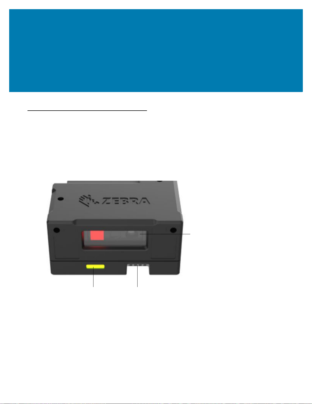
Imager Window
Indicator LED
Beeper
Introduction
The MS4717 fixed mount imager is specifically designed to be mounted into various enclosures such as the
food ordering kiosk in the quick-serve restaurant, to the ticketing kiosk at the airport or amusement park. The
imager provides an easy and flexible integration into most USB host devices and offers high performance
scanning on both 1D and 2D barcodes.
This integration guide includes programming parameters and describes the theory of operation, installation,
specifications, and configuration.
Figure 1 MS4717 Fixed Mount Imager

MS4717 Features
• Quick and easy integration for OEM devices
• Excellent imaging performance on all 1D and 2D barcodes
• USB interface
• LEDs indicating power status and successful decodes
• Easy programming and configuration
• Flexible mounting options
Theory of Operation
During image capture:
1. The image sensor array in the embedded imaging engine captures an image of the barcode through the
engine’s optical lens. If necessary, the engine automatically adjusts illumination, exposure, and other
parameters to obtain the best quality image.
2. The imaging engine sends the image to the MS4717 CPU.
3. The MS4717 CPU processes the image to identify the target barcode(s), decodes them, and transmits the
decoded data to the host.
Getting Started
Set various parameters provided in this guide to adjust the performance of the MS4717 to match the application or
desired usage profile.
4
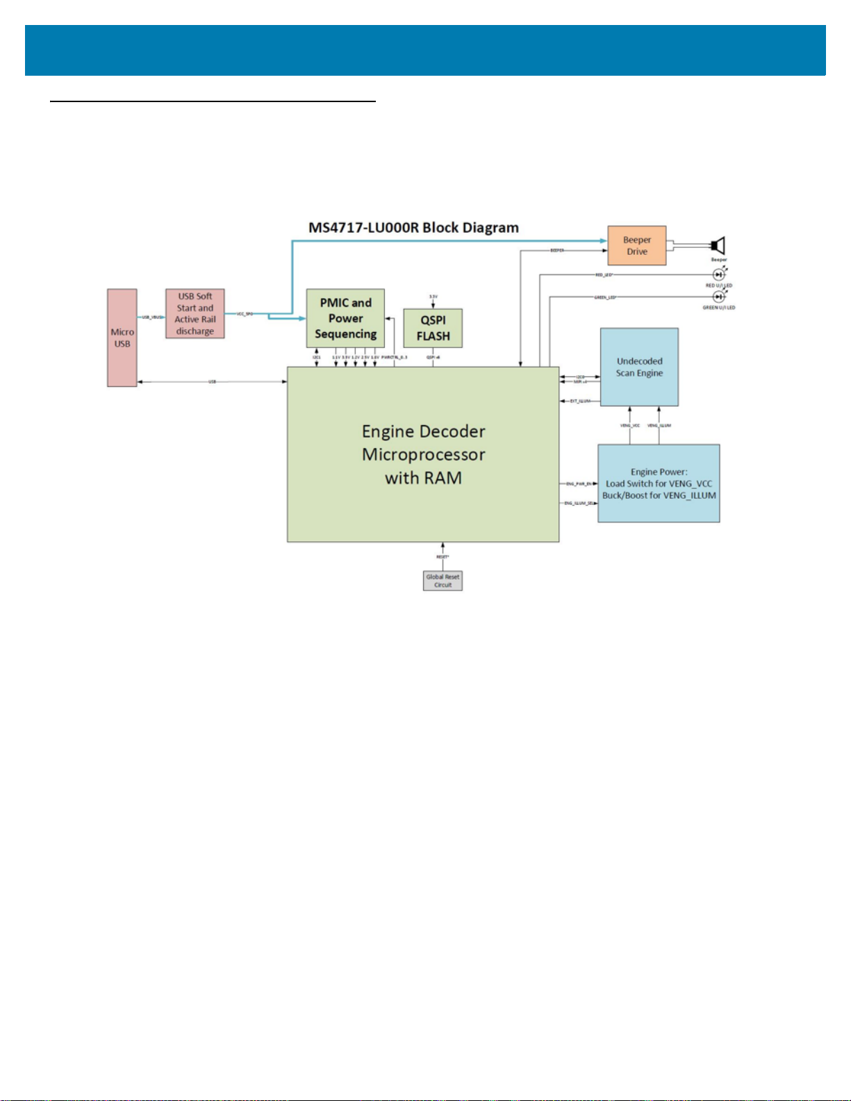
Block Diagram
The MS4717 scanner block diagram illustrates the functional relationship of the MS4717 components. This section
also provides a description of each component in the block diagrams.
Figure 2 MS4717 Block Diagram
Getting Started
MS4717 Block Diagram Descriptions
Scan Engine - The imaging engine captures 8-bit gray scale WVGA images at up to 30 fps, which are sent
uncompressed to a companion board for processing. The engine uses a red LED for intuitive aiming and features
LED illumination.
Decoder Interface - The decoder board is a companion decoder module for the imaging engine, which controls the
engine, receives images, decodes 1D and 2D symbologies, and performs various image processing tasks. The
board controls red and green LEDs for visual feedback, and supports SNAPI (Symbol Native API) as well as USB
HID Keyboard through a micro USB connector. The micro USB connector provides an outlet for the various interface
signals used between the MS4717 and the host.
MS4717 Decoder/Interface Board
Power Management
• USB Host Interface - The MS4717 automatically manages its power usage, including USB suspend
mode. Additionally, when drawing power from the USB bus, the MS4717 does not exceed the USB limit of
500 mA.
5

123Scan
Introduction
This chapter briefly describes the Zebra software tools available for customizing scanner operation.
123Scan
123Scan is a software tool that simplifies scanner setup and more.
Intuitive enough for first time users, the 123Scan wizard guides users through a streamlined setup process.
Settings are saved in a configuration file that can be printed as a single programming barcode for scanning,
emailed to a smart phone for scanning from its screen, or downloaded to the scanner using a USB cable.
Through 123Scan a user can:
• Configure a scanner using a wizard.
• Program the following scanner settings.
• Beeper tone / volume settings.
• Enable / disable symbologies.
• Communication settings.
• Modify data before transmission to a host using Advanced Data Formatting (ADF).
• Load parameter settings to a scanner via the following.
• Barcode scanning.
• Scan a paper barcode.
• Scan a barcode from a PC screen.
• Scan a barcode from a smart phone screen.
• Download over a USB cable.
• Load settings to one scanner.
• Stage up to 10 scanners simultaneously (Powered USB Hub recommended with 0.5 amp / port).
• Validate scanner setup.
• View scanned data within the utility's Data view screen.
• Capture an image and save to a PC within the utility's Data view screen.
• Review settings using the Parameter Report.
• Clone settings from an already deployed scanner from the Start screen.
• Upgrade scanner firmware.
• Load settings to one scanner.
• Stage up to 10 scanners simultaneously (Powered USB Hub recommended with 0.5 amp / port).

123Scan
• View statistics such as:
• Asset tracking information.
• Time and usage information.
• Barcodes scanned by symbology.
• Battery diagnostics (select scanners).
• Generate the following reports.
• Barcode Report - Programming barcode, included parameter settings, and supported scanner models.
• Parameter Report - Parameters programmed within a configuration file.
• Inventory Report - Scanner asset tracking information.
• Validation Report - Scanned data from the Data view.
• Statistics Report - All statistics retrieved from the scanner.
For more information go to: http://www.zebra.com/123Scan.
Communication with 123Scan
Use a USB cable to connect the scanner to a Windows host computer running 123Scan.
123Scan Requirements
• Host computer running Windows XP, 7, 8, and 10
• Scanner
• USB cable.
123Scan Information
For more information on123Scan, go to: http://www.zebra.com/123Scan
For a 1 minute tour of 123Scan, go to: http://www.zebra.com/ScannerHowToVideos
To see a list of all of our software tools, go to: http://www.zebra.com/scannersoftware
7

123Scan
Scanner SDK, Other Software Tools, and Videos
Tackle all your scanner programming needs with our diversified set of software tools. Whether you need to simply
stage a device, or develop a fully featured application with image and data capture as well as asset management,
these tools help you every step of the way.
To download any of the following free tools, go to: http://www.zebra.com/scannersoftware.
• 123Scan configuration utility
• SDKs
• Scanner SDK for Windows
• Scanner SDK for Linux
• Scanner SDK for Android
• Scanner SDK for iOS
• Drivers
• OPOS driver
• JPOS driver
• USB CDC driver
• TWAIN driver
• Scanner Management Service (SMS) for Remote Management
• Windows
• Linux
• Mobile Apps
• Scanner Control App
•Android
•iOS
• Zebra AppGallery
• Scan-To-Connect Utility
•Android
• Windows
• How-To-Videos
Advanced Data Formatting (ADF)
Advanced Data Formatting (ADF) allows customizing data before transmission to the host device. Use ADF to edit
scanned data to suit the host application's requirements. With ADF you scan one barcode per trigger pull. ADF is
programmed using 123Scan.
For a video on Creating an Advanced Data Formatting (ADF) Rule using 123Scan, go to:
http://www.zebra.com/ScannerHowToVideos.
For additional information, refer to the Advanced Data Formatting Programmer Guide.
8

Installation
Introduction
This chapter provides information on mounting and installing the imager.
Mounting
The following figures provide the mounting dimensions.
NOTE: Do not use screws that penetrate more than 5 mm into the bottom mousing of the MS4717
since this is the maximum depth of the useful thread.
MS4717 Mounting Dimensions
Figure 3 Mounting Dimensions (Left Side View)

Installation
Figure 4 MS4717 Mounting Dimensions (Overhead View)
Figure 5 MS4717 Mounting Dimensions (Right Side View)
10

Figure 6 MS4717 Mounting Dimensions
Installation
11

Connecting the MS4717
USB Cable
Clip Ramp
Cable Retention Clip
USB Host Connection
1. Unpack the imager.
2. Remove cable retention clip by lightly pinching the sides of the cable retention clip and sliding away from the
device.
3. Plug USB cable into the device.
4. Place cable retention clip over the USB cable and attach to the MS4717 by pinching the sides of the clip
slightly, using the arrows on the clip (pointing towards device) as a guide until secure.
5. Plug the USB series A into the appropriate port on the host.
6. Check all connections to ensure they are secure.
7. The green power LED illuminates upon connecting and powering on host.
Figure 7 USB Connection
Installation
NOTE: It is recommended that a Zebra USB cable is used for installation (p/n = 25-124330-01R). If
other USB cables used must be compatible with current USB.org requirements.
Please refer to USB.org connectors and compliance documentation for more information
found here:
https://www.usb.org/document-library/usb-type-c-connectors-and-cable-assemblies-complian
ce-document-v12
12

Accessories
Zebra offers additional accessories for the MS4717 through Solution Builder (ordering guide), it is recommended
that this tool is used to order any accessories.
NOTE: To ensure that the USB cable will fit properly with the cable retention clip, it is recommended
that the connector shell size does not exceed 11.5 mm (w) and 8.7 mm (thickness). The width
cannot exceed 12.5 w and 10.5 thickness. The cable connector shell length cannot exceed 17
mm.
Location and Positioning
The location and positioning guidelines do not consider unique application characteristics. Zebra recommends that
an opto-mechanical engineer perform an opto-mechanical analysis prior to integration.
NOTE: Integrate the imager in an environment that is not more extreme than the product’s
specification, where the imager will not exceed its temperature range. For instance, do not
mount the scanner onto or next to a large heat source. When placing the imager with another
device, ensure there is proper convection or venting for heat. Follow these suggestions to
ensure product longevity, warranty, and overall satisfaction with the scanner.
Installation
Embedded Applications Requiring a Window
Use the following guidelines for applications that require a window in front of the MS4717.
NOTE: Zebra does not recommend placing an exit window in front of the MS4717; however, the following
information is provided for applications that require such a window.
13

Installation
Window Material
Many window materials that look clear can contain stresses and distortions that reduce performance. For this
reason, use only cell-cast plastics or optical glass (with or without an anti reflection coating, depending on the
application). Following are descriptions of three popular window materials: PMMA, ADC (CR-39
chemically tempered glass. Table 3-1 outlines the suggested window properties.
Table 3-1 Suggested Window Properties
Property Description
Thickness Typically 0.03 - 0.06 in. (0.7 - 1.5 mm)
Wavefront Distortion (transmission) 0.2 wavelengths peak-to-valley maximum and 0.04 l maximum rms over
any 0.08 in. diameter within the clear aperture
Clear Aperture To extend to within 0.04 in. of the edges all around
Surface Quality 60-20 scratch/dig
When using plastic materials pay extra attention to the wave front distortion recommendation specified above.
Plastic materials are not recommended for tilted windows since surface scratches cause image artifacts. Colored
windows are not recommended if motion detection mode is required since it reduces engine sensitivity to the
moving target.
TM
), and
Cell Cast Acrylic (ASTM: PMMA)
Cell Cast Acrylic, or Poly-methyl Methacrylic (PMMA) is fabricated by casting acrylic between two precision sheets
of glass. This material has very good optical quality, reasonably good impact resistance and low initial cost, but is
relatively soft and susceptible to attack by chemicals, mechanical stresses, and UV light. Therefore polysiloxane
coating is strongly recommended. Acrylic can be laser cut into odd shapes and ultrasonically welded.
Cell Cast ADC (ASTM: ADC)
Also known as CR-39TM, Allyl Diglycol Carbonate (ADC) is a thermal-setting plastic produced by cell-casting. Most
plastic eyeglasses sold today are uncoated, cell-cast CR-39. This material has excellent chemical and
environmental resistance, and reasonably good impact resistance. It also has quite good surface hardness, and
therefore does not have to be hard-coated, but may be coated for severe environments. This material cannot be
ultrasonically welded.
Chemically Tempered Glass
Glass is a hard material that provides excellent scratch and abrasion resistance. However, unannealed glass is
brittle. Increasing flexibility strength with minimal optical distortion requires chemical tempering. Glass cannot be
ultrasonically welded and is difficult to cut into odd shapes.
14

Installation
Commercially Available Coatings
Anti-Reflection Coatings
Anti-reflection coatings can be used for stray light control or to achieve maximum working range, and can be
applied to the inside and/or outside of the window to reduce the amount of light reflected off the window back into
the engine. However, they are expensive and have very poor abrasion and scratch resistance.
Polysiloxane Coating
Polysiloxane type coatings are applied to plastic surfaces to improve the surface resistance to both scratch and
abrasion. To apply, dip and air dry in an oven with filtered hot air.
To gauge a window's durability, use ASTM standard D1044, Standard Test Method for Resistance of Transparent
Plastics to Surface Abrasion (the Taber Test), which quantifies abrasion resistance as a percent increase in haze
after a specified number of cycles and load. Lower values of the increase in haze correspond to better abrasion
and scratch resistance. See Table 3-2.
Table 3-2 Taber Test Results on Common Exit Window Materials
Sample
Chemically Tempered Glass 1.20% 1.50% Best
PMMA with Polysiloxane Hardcoat 3% 10%
ADC 5% 30%
PMMA 30% Worst
* All measurements use a 100 gram load and CS-10F Abraser.
Haze 100
cycles
Haze 500
cycles
Abrasion
Resistance
A Word About Coatings
If using an anti-reflective (AR) coating, the specifications in Table 3-3 apply. Polysiloxane coating is not required.
Recess the exit window to minimize scratches and digs.
Table 3-3 AR Coatings Specifications
Specification Description
Material Both tempered glass and plastic (e.g., CR-39 or hard coated acrylic) exit
windows can be AR coated. AR coated glass is easier and more durable
because of a better adhesion property on the glass structure. In addition, it can
be more cost effective to put an AR coating on the glass substrate rather than
on the plastic.
AR Coating Specification
• Single side AR-coating: 92% minimum transmittance within spectrum
range from 420 nm to 730 nm.
• Double side AR-coating: 97% minimum transmittance within spectrum
range from 420 nm to 730 nm.
• For parallel windows, see Figure 9 on page 18.
15

Installation
Embedded Window Angle and Position
If you are placing a window between the MS4717 and the target, observe the following guidelines:
• Window Clear Opening - Make the clear opening of the window large enough so that the entire imager
clear aperture passes through the window. Cutting off any part of the clear aperture can degrade decode
range performance. Ensure that window placement relative to the MS4717 accounts for tolerances on all
parts involved in that assembly.
• Window Angle - Minimum window tilt is indicated in Table 4. Further tilting the window is acceptable and
decreases the possibility of a secondary reflection from that window degrading the scanner's performance.
• Minimum Window Distance - (TBD)
• Optical Working Range - Adding a window can reduce the working range of the scanner since there is a
signal loss when passing through window material. To minimize this reduction, use a special coating
described in A Word About Coatings on page 15. To understand the difference, test the scanner in the
desired orientation and see if the difference affects scanner performance.
16
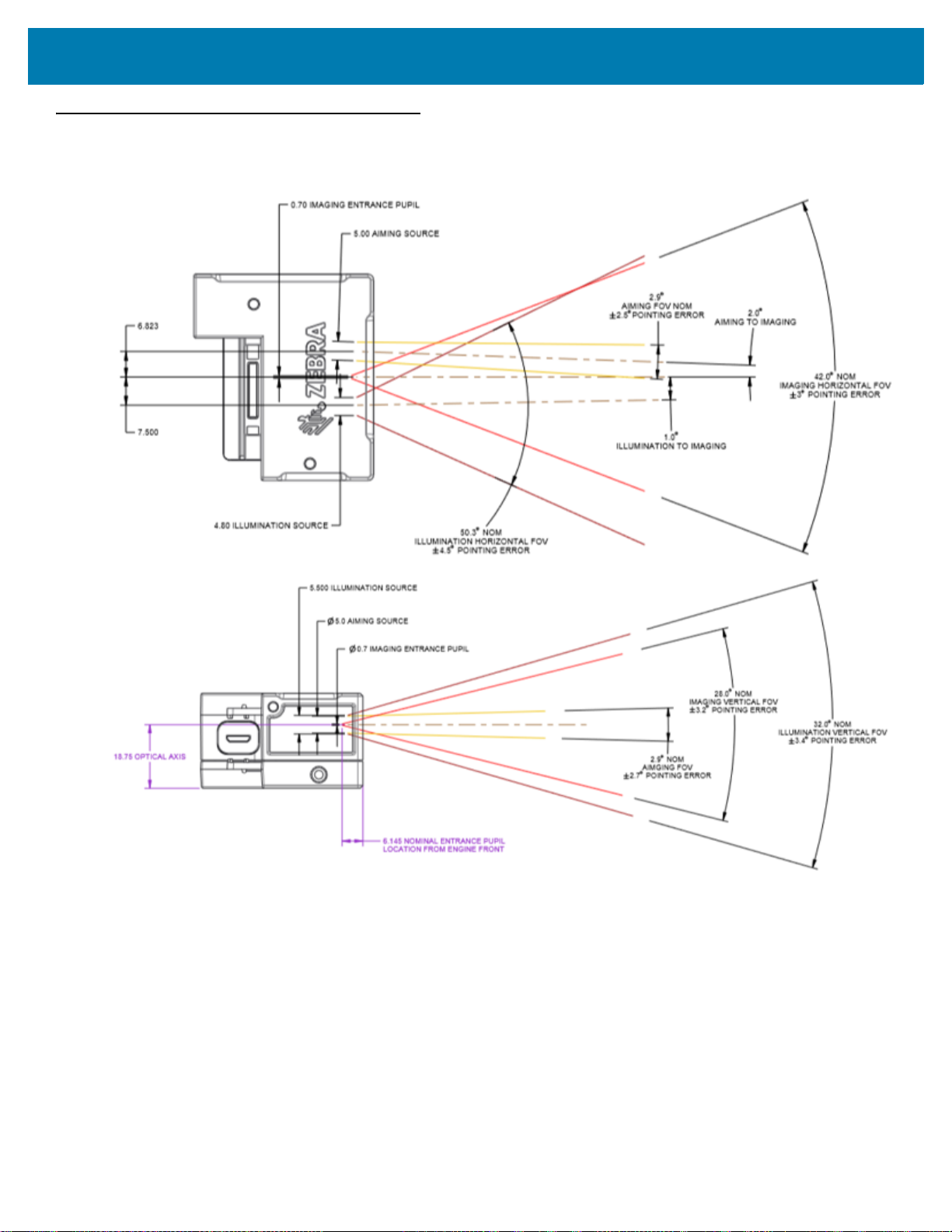
Optical Path
Notes:
1. Imaging axis pointing tolerance vs. datums ABC:
± 3º horizontal; ± 3.2º vertical
2. Clipping the scanner clear aperture is not permitted.
3. Dimensions are in mm.
Figure 8 MS4717 Optical Path and Exit Window
Installation
17
Installation
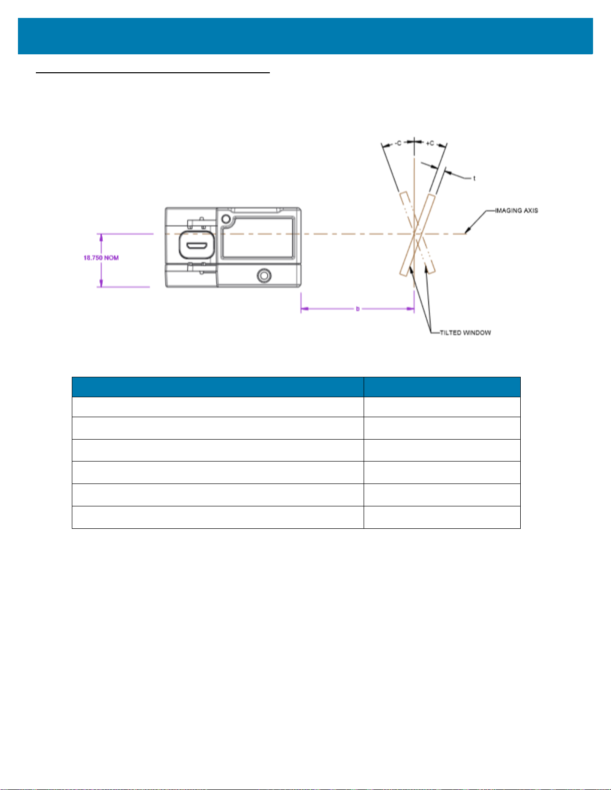
Recommended Exit Window Information
Figure 9 Exit Window Distance Information
Table 4 Recommended Exit Window Information - Tilted Window
External Window Specification Minimum Window Angle
Non-coated, minimum window positive tilt (+c) TBD
Non-coated, minimum window negative tilt (-c)
AR coated, one side, minimum window positive tilt (+c)
AR coated, one side, minimum window negative tilt (-c)
AR coated, two sides, minimum window positive tilt (+c)
AR coated, two sides, minimum window negative tilt (-c)
Exit Window Notes
• Integration tolerances are not included.
• Ensure the window size is large enough to cover the engine clear aperture plus mounting tolerances of the
window relative to the engine.
TBD
TBD
TBD
TBD
TBD
18

Installation
Zebra SNAPI Software Developer's Kit
The Symbol Native Application Programming Interface Software Development Kit (SNAPI SDK) facilitates
communicate with SNAPI-based Zebra scanners over USB, providing the following features:
• Barcode capture and decode
• Image and video capture
• Electronic scanner configuration and software update
• Reference sample application in Microsoft Visual C#
To download the SDK, go to: www.zebra.com/support.
®
.NET.
19

Scanning
Introduction
This chapter provides information on aiming, illumination, data capture, beeper and decode LED feedback,
supported symbologies, and operating modes.
Imaging System
Aiming System
A 610 nm LED is used to generate a circular aiming pattern which indicates the center of the imager’s field of
view.
Aiming with MS4717
When scanning, the device projects an orange LED dot, which allows positioning the barcode within its field of
view. If necessary, the imager turns on its red LEDs to illuminate the target barcode.
To scan a barcode, center the symbol and ensure the entire symbol is within the rectangular area formed by
the illumination LEDs. The imager can also read a barcode presented within the aiming dot not centered. The
figure below illustrates proper LED placement to produce a successful decode.
Figure 10 MS4717 Aiming Pattern
Aiming Error
The aiming pattern is rotated by 2º relative to the imaging axis in the horizontal plane to minimize parallax
between the aiming axis and the imaging axis at 190.45 mm (7.5 in.) from the front of the MS4717.
Aiming Control
The MS4717 can capture images with both the aiming subsystem turned on during exposure (the image of the
aiming pattern is visible in the digital image) or off. If the aiming system is turned off during exposure,
brightness of the aiming pattern decreases as exposure increases.
 Loading...