

Page 1

DS4800 SERIES CORDED
DIGITAL IMAGER
PRODUCT REFERENCE
GUIDE
Page 2

Page 3

DS4800 SERIES CORDED DIGITAL IMAGER
PRODUCT REFERENCE GUIDE
MN000099A05
Revision A
August 2016
Page 4

ii DS4800 Series Corded Digital Imager Product Reference Guide
No part of this publication may be reproduced or used in any form, or by any electrical or mechanical means,
without permission in writing from Zebra. This includes electronic or mechanical means, such as photo copying,
recording, or information storage and retrieval systems. The material in this manual is subject to change
without notice.
The software is provided strictly on an “as is” basis. All software, including firmware, furnished to the user is on
a licensed basis. Zebra grants to the user a non-transferable and non-exclusive license to use each software
or firmware program delivered hereunder (licensed program) . Except as n oted below, such licen se may not b e
assigned, sublicensed, or otherwise tran sfe rr e d by th e user without prior written consent of Zebra. No right to
copy a licensed program in whole or in part is granted, except as permitted under copyright law. The user shall
not modify , merge, or incorporate any for m or portion of a licensed program with other pro gram material, create
a derivative work from a licensed program , or us e a li censed program in a network without written permission
from Zebra. The user agrees to maintain Zebra’s copyright notice on the licensed programs delivered
hereunder , and to include the same on any au thorized copies it m akes, in whole or in part. The user agrees not
to decompile, disassemble, decode, or reverse engineer any licensed program delivered to the user or any
portion thereof.
Zebra reserves the right to make changes to any product to improve reliability, function, or design.
Zebra does not assume any product liability arising out of, or in connection with, the application or use of any
product, circuit, or application described herein.
No license is granted, either expressly or by implication, estoppel, or otherwise under any Zebra Technologies
Corporation, intellectual property rights. An implied license only exists for equipment, circuits, and su bsystems
contained in Zebra products.
This media, or Zebra Product, may include Zebra Software, Commercial Third Party Software, and Publicly
Available Software.
The Zebra Software that may be included on this media, or included in the Zebra Product, is Copyright (c) by
Zebra Technologies Corporation, and its use is subject to the licenses, terms and conditions of the agreement
in force between the purchaser of the Zebra Product and Zebra Technologies Corporation.
The Commercial Third Party Software that may be include d o n this medi a, or includ ed in the Zebr a Prod uct, is
subject to the licenses, terms and conditions of the agreement in force between the purchaser of the Zebra
Product and Zebra Technologies Corporation, unless a separate Commercial Third Party Software License is
included, in which case, your use of the Commercial Third Party Software will then be governed by the
separate Commercial Third Party License.
The Publicly A vailable Software that may be included on this media, or in the Zebra Product, is listed below.
The use of the listed Publicly Available Software is subject to the licenses, terms and conditions of the
agreement in force between the purchaser of the Zebra Product and Zebra Technologies Corporation, as well
as, the terms and conditions of the license of each Publicly Available Software package. Copies of the licenses
for the listed Publicly Available Software, as well as, all attributions, acknowledgements, and software
information details, are included below. Zebra is required to reproduce the software licenses,
acknowledgments and copyright notices as provided by the Authors and Owners, thus, all such information is
provided in its native language form, without modification or translatio n.
The Publicly A vailable Software in the list below is limited to the Publicly Available Software included by Zebra.
The Publicly A vailable Software included by Commercial Third Party Software or Products, that is used in the
Zebra Product, are disclosed in the Commerical Third Party Licenses, or via the respective Commercial Third
Party Publicly Available Software Legal Notices.
Page 5

iii
Publicly available software list:
Name: Regular Expression Evaluator
Version: 8.3
Description: Compiles and executes regular expressions
Software Site: http://www.freebsd.org/cgi/cvsweb.cgi/src/lib/libc/regex/
Source Code: No Source Distribution Obligations. Seller will not provide nor distribute the Source Code for the
Regular Expression Evaluator.
License: BSD Style License
© 1992 Henry Spencer.
© 1992, 1993 The Regents of the University of California. All rights reserved.
This code is derived from software contributed to Berkeley by Henry Spencer of the University of Toronto.
Redistribution and use in source and binary forms, with or without modification, are permitted provided that the
following conditions are met:
1. Redistributions of source code must retain th e above copyright notice, this list of co nditions and the following
disclaimer.
2. Redistributions in binary form must reproduce the above copyright notice, this list of conditions and the
following disclaimer in the documentation and/or other materials provided with the distribution.
3. All advertising materials mentioning features or use of this software must display the following
acknowledgement:
This product includes software developed by the University of California, Berkeley and its contributors.
4. Neither the name of the University nor the names of its contributors may be used to endorse or promote
products derived from this software without specific prior written permission.
THIS SOFTWARE IS PROVIDED BY THE REGENTS AND CONTRIBUTORS ``AS IS'' AND ANY EXPRESS
OR IMPLIED WARRANTIES, INCLUDING, BUT NOT LIMITED TO, THE IMPLIED WARRANTIES OF
MERCHANTABILITY AND FITNESS FOR A PARTICULAR PURPOSE ARE DISCLAIMED. IN NO EVENT
SHALL THE REGENTS OR CONTRIBUTORS BE LIABLE FOR ANY DIRECT, INDIRECT, INCIDENTAL,
SPECIAL, EXEMPLARY, OR CONSEQUENTIAL DAMAGES (INCLUDING, BUT NOT LIMITED TO,
PROCUREMENT OF SUBSTITUTE GOODS OR SERVICES; LOSS OF USE, DATA, OR PROFITS; OR
BUSINESS INTERRUPTION) HOWEVER CAUSED AND ON ANY THEORY OF LIABILITY, WHETHER IN
CONTRACT, STRICT LIABILITY, OR TORT (INCLUDING NEGLIGENCE OR OTHERWISE) ARI SING IN ANY
WAY OUT OF THE USE OF THIS SOFTWARE, EVEN IF ADVISED OF THE POSSIBILITY OF SUCH
DAMAGE.
Warranty
For the complete Zebra hardware product warranty statement, go to: http://www.zebra.com/warranty
Page 6

iv DS4800 Series Corded Digital Imager Product Reference Guide
Revision History
Changes to the original guide are listed below:
Change Date Description
-01 Rev A 4/2014 Initial release
-02 Rev A 6/2014 Added Toshiba TEC QR Pre-Scan Parsing parameters, changed Decode
Illumination Indicator parameter to Direct Decode Indicator, updated default for
Mobile Phone/Display Mode, added Customizable Scan Tone instructions
-03 Rev A 2/2015 Rebranded, added Quiet Zone parameters and Ignore Code 128 <FNC4>
parameter, added Communication Protocol Functionality appendix
-04 Rev A 6/2015 - Removed Toshiba TEC host bar code and parameters
- Added Notes to Tone on Trigger Touch, Hand-Held Decode Aiming Pattern,
and Picklist Mode parameters
- Added GS1 Data Matrix and GS1 QR code types
- Added Downloading a Custom Tone via 123Scan2 section
-05 Rev A 8/2016 - Added USB Direct I/O Beep parameter
- Updated descriptions for USB Beep Directive and Bar Code Configuration
Directive parameters
- Updated Code 128 length range for PDF Prioritization parameter
- Added Mailmark parameter
- Removed QR Inverse parameter
- Added GS1 Data Matrix, GS1 QR, and Mailmark to Symbol ID, AIM Code ID,
and Modifier Character tables
Page 7

TABLE OF CONTENTS
About This Guide
Introduction..................................................................................................................................... xv
Configurations................................................................................................................................. xv
Chapter Descriptions ...................................................................................................................... xv
Notational Conventions................................................................................................................... xvii
Related Documents ........................................................................................................................ xvii
Service Information......................................................................................................................... xviii
Chapter 1: Getting Started
Introduction .................................................................................................................................... 1-1
Unpacking ...................................................................................................................................... 1-1
Imager Parts .................................................................................................................................. 1-2
Host Connection ............................................................................................................................ 1-3
DS4800 Series Presentation Stand ............................................................................................... 1-4
Assembling the Stand .............................................................................................................. 1-4
Configuring the Imager .................................................................................................................. 1-5
Chapter 2: Data Capture
Introduction .................................................................................................................................... 2-1
User Feedback Definitions ............................................................................................................. 2-1
Scanning ........................................................................................................................................ 2-4
Hand-Held Triggered Scanning ............................................................................................... 2-4
Hands-Free Presentation Scanning ......................................................................................... 2-5
Hand-Held Presentation Scanning ........................................................................................... 2-6
Chapter 3: USB Interface
Introduction .................................................................................................................................... 3-1
USB Parameter Defaults ................................................................................................................ 3-2
USB Host Parameters .................................................................................................................... 3-3
USB Device Type ..................................................................................................................... 3-3
Symbol Native API (SNAPI) Status Handshaking .................................................................... 3-5
Page 8

vi DS4800 Series Corded Digital Imager Product Reference Guide
USB Keystroke Delay .............................................................................................................. 3-5
USB CAPS Lock Override ....................................................................................................... 3-6
USB Ignore Unknown Characters ............................................................................................ 3-6
USB Convert Unknown to Code 39 ......................................................................................... 3-7
Emulate Keypad ....................................................................................................................... 3-7
Emulate Keypad with Leading Zero ......................................................................................... 3-8
Quick Keypad Emulation .......................................................................................................... 3-8
USB Keyboard FN 1 Substitution ............................................................................................. 3-9
Function Key Mapping ............................................................................................................. 3-9
Simulated Caps Lock ............................................................................................................... 3-10
Convert Case ........................................................................................................................... 3-10
USB Polling Interval ................................................................................................................. 3-11
USB Fast HID .......................................................................................................................... 3-12
USB Static CDC ....................................................................................................................... 3-13
Direct I/O Beep ........................................................................................................................ 3-13
Beep Directive .......................................................................................................................... 3-14
Bar Code Configuration Directive ............................................................................................ 3-14
IBM Specification Version ........................................................................................................ 3-15
ASCII Character Set for USB ......................................................................................................... 3-16
Chapter 4: User Preferences & Miscellaneous Options
Introduction .................................................................................................................................... 4-1
User Experience ............................................................................................................................ 4-2
Scanning Sequence Examples ...................................................................................................... 4-2
Errors While Scanning ................................................................................................................... 4-2
User Preferences/Miscellaneous Options Parameter Defaults ...................................................... 4-2
User Preferences ........................................................................................................................... 4-5
Default Parameters .................................................................................................................. 4-5
Report Version ......................................................................................................................... 4-6
Parameter Bar Code Scanning ................................................................................................ 4-6
Beep After Good Decode ......................................................................................................... 4-7
Direct Decode Indicator ........................................................................................................... 4-8
Speaker Volume ...................................................................................................................... 4-9
Scan Tone ................................................................................................................................ 4-10
Suppress Power Up Beeps ...................................................................................................... 4-12
LED on Good Decode .............................................................................................................. 4-12
Haptic Feedback (Vibrate) on Good Decode ........................................................................... 4-13
Haptic Feedback (Vibrate) on Good Decode Duration ............................................................ 4-14
Haptic Feedback (Vibrate) on Trigger Touch ........................................................................... 4-16
Tone on Trigger Touch ............................................................................................................ 4-16
Hand-Held Triggered Mode ..................................................................................................... 4-17
Hand-Held Decode Aiming Pattern .......................................................................................... 4-18
Hands-Free Decode Aiming Pattern ........................................................................................ 4-19
Picklist Mode ............................................................................................................................ 4-20
Continuous Bar Code Read ..................................................................................................... 4-21
Unique Bar Code Reporting ..................................................................................................... 4-21
Decode Session Timeout ......................................................................................................... 4-22
Timeout Between Decodes, Same Symbol ............................................................................. 4-22
Timeout Between Decodes, Different Symbols ....................................................................... 4-23
Fuzzy 1D Processing ............................................................................................................... 4-23
Page 9

Table of Contents vii
Decode Mirror Images (Data Matrix Only) ............................................................................... 4-24
Mobile Phone/Display Mode .................................................................................................... 4-25
PDF Prioritization ..................................................................................................................... 4-26
PDF Prioritization Timeout ....................................................................................................... 4-26
Presentation Mode Field of View ............................................................................................. 4-27
Decoding Illumination ............................................................................................................... 4-28
Low Light Scene Detection ...................................................................................................... 4-29
Motion Tolerance (Hand-Held Triggered Modes Only) ............................................................ 4-30
Miscellaneous Imager Parameters ................................................................................................ 4-31
Transmit Code ID Character .................................................................................................... 4-31
Prefix/Suffix Values .................................................................................................................. 4-32
Scan Data Transmission Format ............................................................................................. 4-33
FN1 Substitution Values .......................................................................................................... 4-34
Transmit “No Read” Message .................................................................................................. 4-35
Unsolicited Heartbeat Interval .................................................................................................. 4-36
Chapter 5: Imaging Preferences
Introduction .................................................................................................................................... 5-1
Scanning Sequence Examples ...................................................................................................... 5-2
Errors While Scanning ................................................................................................................... 5-2
Imaging Preferences Parameter Defaults ...................................................................................... 5-2
Imaging Preferences ...................................................................................................................... 5-4
Operational Modes ................................................................................................................... 5-4
Image Capture Illumination ...................................................................................................... 5-5
Snapshot Mode Timeout .......................................................................................................... 5-6
Snapshot Aiming Pattern ......................................................................................................... 5-6
Image Cropping ....................................................................................................................... 5-7
Crop to Pixel Addresses .......................................................................................................... 5-8
Image Size (Number of Pixels) ................................................................................................ 5-9
Image Brightness (Target White) ............................................................................................. 5-10
JPEG Image Options ............................................................................................................... 5-10
JPEG Target File Size ............................................................................................................. 5-11
JPEG Quality Value ................................................................................................................. 5-11
Image Enhancement ................................................................................................................ 5-12
Image File Format Selector ...................................................................................................... 5-13
Image Rotation ......................................................................................................................... 5-14
Bits Per Pixel ............................................................................................................................ 5-15
Signature Capture .................................................................................................................... 5-16
Signature Capture File Format Selector .................................................................................. 5-17
Signature Capture Bits Per Pixel ............................................................................................. 5-18
Signature Capture Width .......................................................................................................... 5-19
Signature Capture Height ........................................................................................................ 5-19
Signature Capture JPEG Quality ............................................................................................. 5-19
Chapter 6: Symbologies
Introduction .................................................................................................................................... 6-1
Scanning Sequence Examples ...................................................................................................... 6-1
Errors While Scanning ................................................................................................................... 6-2
Symbology Parameter Defaults ..................................................................................................... 6-2
Page 10

viii DS4800 Series Corded Digital Imager Product Reference Guide
Enable/Disable All Code Types ..................................................................................................... 6-7
UPC/EAN ....................................................................................................................................... 6-8
Enable/Disable UPC-A ............................................................................................................. 6-8
Enable/Disable UPC-E ............................................................................................................. 6-8
Enable/Disable UPC-E1 ........................................................................................................... 6-9
Enable/Disable EAN-8/JAN-8 .................................................................................................. 6-9
Enable/Disable EAN-13/JAN-13 .............................................................................................. 6-10
Enable/Disable Bookland EAN ................................................................................................ 6-10
Bookland ISBN Format ............................................................................................................ 6-11
Decode UPC/EAN/JAN Supplementals ................................................................................... 6-12
User-Programmable Supplementals ........................................................................................ 6-15
UPC/EAN/JAN Supplemental Redundancy ............................................................................. 6-15
UPC/EAN/JAN Supplemental AIM ID Format .......................................................................... 6-16
Transmit UPC-A Check Digit ................................................................................................... 6-17
Transmit UPC-E Check Digit ................................................................................................... 6-17
Transmit UPC-E1 Check Digit ................................................................................................. 6-18
UPC-A Preamble ..................................................................................................................... 6-19
UPC-E Preamble ..................................................................................................................... 6-20
UPC-E1 Preamble ................................................................................................................... 6-21
Convert UPC-E to UPC-A ........................................................................................................ 6-22
Convert UPC-E1 to UPC-A ...................................................................................................... 6-22
EAN-8/JAN-8 Extend ............................................................................................................... 6-23
UCC Coupon Extended Code .................................................................................................. 6-23
Coupon Report ......................................................................................................................... 6-24
ISSN EAN ................................................................................................................................ 6-25
UPC Reduced Quiet Zone ....................................................................................................... 6-25
Code 128 ....................................................................................................................................... 6-26
Enable/Disable Code 128 ........................................................................................................ 6-26
Set Lengths for Code 128 ........................................................................................................ 6-26
Enable/Disable GS1-128 (formerly UCC/EAN-128) ................................................................. 6-28
Enable/Disable ISBT 128 ......................................................................................................... 6-28
ISBT Concatenation ................................................................................................................. 6-29
Check ISBT Table .................................................................................................................... 6-30
ISBT Concatenation Redundancy ............................................................................................ 6-30
Ignore Code 128 <FNC4> ........................................................................................................ 6-31
Code 128 Security Level .......................................................................................................... 6-32
Code 128 Reduced Quiet Zone ............................................................................................... 6-33
Code 39 ......................................................................................................................................... 6-34
Enable/Disable Code 39 .......................................................................................................... 6-34
Enable/Disable Trioptic Code 39 ............................................................................................. 6-34
Convert Code 39 to Code 32 ................................................................................................... 6-35
Code 32 Prefix ......................................................................................................................... 6-35
Set Lengths for Code 39 .......................................................................................................... 6-36
Code 39 Check Digit Verification ............................................................................................. 6-37
Transmit Code 39 Check Digit ................................................................................................. 6-37
Code 39 Full ASCII Conversion ............................................................................................... 6-38
Code 39 Security Level ............................................................................................................ 6-39
Code 39 Reduced Quiet Zone ................................................................................................. 6-40
Code 93 ......................................................................................................................................... 6-41
Enable/Disable Code 93 .......................................................................................................... 6-41
Set Lengths for Code 93 .......................................................................................................... 6-41
Page 11

Table of Contents ix
Code 11 ......................................................................................................................................... 6-43
Code 11 ................................................................................................................................... 6-43
Set Lengths for Code 11 .......................................................................................................... 6-43
Code 11 Check Digit Verification ............................................................................................. 6-45
Transmit Code 11 Check Digits ............................................................................................... 6-46
Interleaved 2 of 5 (ITF) .................................................................................................................. 6-47
Enable/Disable Interleaved 2 of 5 ............................................................................................ 6-47
Set Lengths for Interleaved 2 of 5 ............................................................................................ 6-47
I 2 of 5 Check Digit Verification ................................................................................................ 6-49
Transmit I 2 of 5 Check Digit .................................................................................................... 6-50
Convert I 2 of 5 to EAN-13 ....................................................................................................... 6-50
I 2 of 5 Security Level .............................................................................................................. 6-51
I 2 of 5 Reduced Quiet Zone .................................................................................................... 6-52
Discrete 2 of 5 (DTF) ..................................................................................................................... 6-53
Enable/Disable Discrete 2 of 5 ................................................................................................. 6-53
Set Lengths for Discrete 2 of 5 ................................................................................................ 6-53
Codabar (NW - 7) ........................................................................................................................... 6-55
Enable/Disable Codabar .......................................................................................................... 6-55
Set Lengths for Codabar .......................................................................................................... 6-55
CLSI Editing ............................................................................................................................. 6-57
NOTIS Editing .......................................................................................................................... 6-57
Codabar Upper or Lower Case Start/Stop Characters Detection ............................................ 6-58
MSI ................................................................................................................................................. 6-59
Enable/Disable MSI ................................................................................................................. 6-59
Set Lengths for MSI ................................................................................................................. 6-59
MSI Check Digits ..................................................................................................................... 6-61
Transmit MSI Check Digit(s) .................................................................................................... 6-61
MSI Check Digit Algorithm ....................................................................................................... 6-62
Chinese 2 of 5 ................................................................................................................................ 6-63
Enable/Disable Chinese 2 of 5 ................................................................................................. 6-63
Matrix 2 of 5 ................................................................................................................................... 6-64
Enable/Disable Matrix 2 of 5 .................................................................................................... 6-64
Set Lengths for Matrix 2 of 5 .................................................................................................... 6-64
Matrix 2 of 5 Check Digit .......................................................................................................... 6-66
Transmit Matrix 2 of 5 Check Digit ........................................................................................... 6-66
Korean 3 of 5 ................................................................................................................................. 6-67
Enable/Disable Korean 3 of 5 .................................................................................................. 6-67
Inverse 1D ...................................................................................................................................... 6-68
GS1 DataBar .................................................................................................................................. 6-69
GS1 DataBar-14 ...................................................................................................................... 6-69
GS1 DataBar Limited ............................................................................................................... 6-69
GS1 DataBar Expanded .......................................................................................................... 6-70
Convert GS1 DataBar to UPC/EAN ......................................................................................... 6-70
GS1 DataBar Limited Security Level ....................................................................................... 6-71
Composite ...................................................................................................................................... 6-72
Composite CC-C ...................................................................................................................... 6-72
Composite CC-A/B ................................................................................................................... 6-72
Composite TLC-39 ................................................................................................................... 6-73
UPC Composite Mode ............................................................................................................. 6-73
Composite Beep Mode ............................................................................................................ 6-74
GS1-128 Emulation Mode for UCC/EAN Composite Codes .................................................... 6-74
Page 12

x DS4800 Series Corded Digital Imager Product Reference Guide
Postal Codes ................................................................................................................................. 6-75
US Postnet ............................................................................................................................... 6-75
US Planet ................................................................................................................................. 6-75
Transmit US Postal Check Digit ............................................................................................... 6-76
UK Postal ................................................................................................................................. 6-76
Transmit UK Postal Check Digit ............................................................................................... 6-77
Japan Postal ............................................................................................................................ 6-77
Australia Post ........................................................................................................................... 6-78
Australia Post Format .............................................................................................................. 6-79
Netherlands KIX Code ............................................................................................................ 6-80
USPS 4CB/One Code/Intelligent Mail ...................................................................................... 6-80
UPU FICS Postal ..................................................................................................................... 6-81
Mailmark .................................................................................................................................. 6-81
2D Symbologies ............................................................................................................................. 6-82
Enable/Disable PDF417 ........................................................................................................... 6-82
Enable/Disable MicroPDF417 .................................................................................................. 6-82
Code 128 Emulation ................................................................................................................ 6-83
Data Matrix ............................................................................................................................... 6-84
GS1 Data Matrix ...................................................................................................................... 6-84
Data Matrix Inverse .................................................................................................................. 6-85
Maxicode .................................................................................................................................. 6-85
QR Code .................................................................................................................................. 6-86
GS1 QR .................................................................................................................................. 6-86
MicroQR ................................................................................................................................... 6-87
Aztec ........................................................................................................................................ 6-88
Aztec Inverse ........................................................................................................................... 6-88
Han Xin .................................................................................................................................... 6-89
Han Xin Inverse ....................................................................................................................... 6-89
Redundancy Level ......................................................................................................................... 6-90
Redundancy Level 1 ................................................................................................................ 6-90
Redundancy Level 2 ................................................................................................................ 6-90
Redundancy Level 3 ................................................................................................................ 6-90
Redundancy Level 4 ................................................................................................................ 6-91
Security Level ................................................................................................................................ 6-92
1D Quiet Zone Level ...................................................................................................................... 6-93
Intercharacter Gap Size ................................................................................................................. 6-94
Report Version ............................................................................................................................... 6-94
Macro PDF Features ..................................................................................................................... 6-95
Flush Macro Buffer ................................................................................................................... 6-95
Abort Macro PDF Entry ............................................................................................................ 6-95
Chapter 7: Intelligent Document Capture
Introduction .................................................................................................................................... 7-1
The IDC Process ........................................................................................................................... 7-1
Bar Code Acceptance Test ...................................................................................................... 7-2
Capture Region Determination ................................................................................................ 7-2
Image Post Processing ............................................................................................................ 7-3
Data Transmission ........................................... ........................................................................ 7-3
PC Application and Programming Support .................................................................................... 7-3
Page 13

Table of Contents xi
Parameters .................................................................................................................................... 7-4
IDC Operating Mode ................................................................................................................ 7-5
IDC Symbology ........................................................................................................................ 7-6
IDC X Coordinate ..................................................................................................................... 7-7
IDC Y Coordinate ..................................................................................................................... 7-7
IDC Width ................................................................................................................................. 7-8
IDC Height ............................................................................................................................... 7-8
IDC Aspect ............................................................................................................................... 7-9
IDC File Format Selector ......................................................................................................... 7-9
IDC Bits Per Pixel .................................................................................................................... 7-10
IDC JPEG Quality .................................................................................................................... 7-10
IDC Find Box Outline ............................................................................................................... 7-11
IDC Minimum Text Length ....................................................................................................... 7-11
IDC Maximum Text Length ...................................................................................................... 7-12
IDC Captured Image Brighten .................................................................................................. 7-12
IDC Captured Image Sharpen ................................................................................................. 7-13
IDC Border Type ...................................................................................................................... 7-14
IDC Delay Time ........................................................................................................................ 7-15
IDC Zoom Limit ........................................................................................................................ 7-15
IDC Maximum Rotation ............................................................................................................ 7-16
Quick Start ..................................................................................................................................... 7-17
Sample IDC Setup ................................................................................................................... 7-17
IDC Demonstrations ................................................................................................................. 7-18
Other Suggestions ................................................................................................................... 7-19
Quick Start Form ...................................................................................................................... 7-19
Chapter 8: OCR Programming
Introduction .................................................................................................................................... 8-1
OCR Parameter Defaults ............................................................................................................... 8-2
OCR Programming Parameters ..................................................................................................... 8-3
Enable/Disable OCR-A ............................................................................................................ 8-3
OCR-A Variant ......................................................................................................................... 8-3
Enable/Disable OCR-B ............................................................................................................ 8-5
OCR-B Variant ......................................................................................................................... 8-6
Enable/Disable MICR E13B ..................................................................................................... 8-9
Enable/Disable US Currency Serial Number ........................................................................... 8-10
OCR Orientation ...................................................................................................................... 8-10
OCR Lines ............................................................................................................................... 8-12
OCR Minimum Characters ....................................................................................................... 8-12
OCR Maximum Characters ...................................................................................................... 8-13
OCR Subset ............................................................................................................................. 8-13
OCR Quiet Zone ...................................................................................................................... 8-14
OCR Template ......................................................................................................................... 8-15
OCR Check Digit Modulus ....................................................................................................... 8-24
OCR Check Digit Multiplier ...................................................................................................... 8-25
OCR Check Digit Validation ..................................................................................................... 8-26
Inverse OCR ............................................................................................................................ 8-31
Page 14

xii DS4800 Series Corded Digital Imager Product Reference Guide
Chapter 9: Driver’s License Set Up (DS4801-DL)
Introduction .................................................................................................................................... 9-1
Driver’s License Parsing ................................................................................................................ 9-2
Parsing Driver’s License Data Fields (Embedded Driver's License Parsing) ................................ 9-3
Embedded Driver's License Parsing Criteria - Code Type ...................................................... 9-3
Driver’s License Parse Field Bar Codes .................................................................................. 9-4
AAMVA Parse Field Bar Codes ............................................................................................... 9-7
User Preferences ........................................................................................................................... 9-17
Set Default Parameter ............................................................................................................. 9-17
Output Gender as M or F ......................................................................................................... 9-17
Date Format ............................................................................................................................. 9-18
Send Keystroke (Control Characters and Keyboard Characters) ............................................ 9-20
Parsing Rule Example ................................................................................................................... 9-39
Embedded Driver's License Parsing ADF Example ................................................................. 9-43
Chapter 10: 123Scan2
Introduction .................................................................................................................................... 10-1
Communication with 123Scan2 ..................................................................................................... 10-1
123Scan2 Requirements ............................................................................................................... 10-2
Scanner SDK, Other Software Tools, and Videos ......................................................................... 10-2
Chapter 11: Advanced Data Formatting
Introduction .................................................................................................................................... 11-1
Chapter 12: Maintenance & Technical Specifications
Introduction .................................................................................................................................... 12-1
Maintenance .................................................................................................................................. 12-1
Known Harmful Ingredients ...................................................................................................... 12-1
Approved Cleaning Agents ...................................................................................................... 12-2
Cleaning the Imager ................................................................................................................. 12-2
Troubleshooting ............................................................................................................................. 12-3
Technical Specifications ................................................................................................................ 12-5
Appendix A: Standard Default Parameters
Appendix B: Country Codes
Introduction .................................................................................................................................... B-1
USB Country Keyboard Types (Country Codes) ........................................................................... B-2
Appendix C: Country Code Pages
Introduction .................................................................................................................................... C-1
Country Code Page Defaults ......................................................................................................... C-1
Country Code Page Bar Codes ..................................................................................................... C-5
Page 15

Table of Contents xiii
Appendix D: CJK Decode Control
Introduction .................................................................................................................................... D-1
CJK Control Parameters ................................................................................................................ D-2
Unicode Output Control ........................................................................................................... D-2
CJK Output Method to Windows Host ..................................................................................... D-3
Non-CJK UTF Bar Code Output .............................................................................................. D-5
Unicode/CJK Decode Setup with Windows Host ........................................................................... D-7
Setting Up the Windows Registry Table for Unicode Universal Output ................................... D-7
Adding CJK IME on Windows .................................................................................................. D-7
Selecting the Simplified Chinese Input Method on the Host .................................................... D-8
Selecting the Traditional Chinese Input Method on the Host ................................................... D-9
Appendix E: Programming Reference
Symbol Code Identifiers ................................................................................................................. E-1
AIM Code Identifiers ...................................................................................................................... E-3
Appendix F: Sample Bar Codes
Code 39 ......................................................................................................................................... F-1
UPC/EAN ....................................................................................................................................... F-1
UPC-A, 100% ........................................................................................................................... F-1
EAN-13, 100% ......................................................................................................................... F-2
Code 128 ....................................................................................................................................... F-2
Interleaved 2 of 5 ........................................................................................................................... F-2
GS1 DataBar-14 ............................................................................................................................ F-3
PDF417 .......................................................................................................................................... F-3
Data Matrix ..................................................................................................................................... F-3
Maxicode ........................................................................................................................................ F-3
QR Code ........................................................................................................................................ F-4
US Postnet ..................................................................................................................................... F-4
UK Postal ....................................................................................................................................... F-4
Appendix G: Numeric Bar Codes
Numeric Bar Codes ........................................................................................................................ G-1
Cancel ............................................................................................................................................ G-2
Appendix H: ASCII Character Sets
Appendix I: Communication Protocol Functionality
Functionality Supported via Communication (Cable) Interface ...................................................... I-1
Appendix J: Signature Capture Code
Introduction .................................................................................................................................... J-1
Code Structure ............................................................................................................................... J-1
Signature Capture Area ........................................................................................................... J-1
CapCode Pattern Structure ...................................................................................................... J-2
Page 16

xiv DS4800 Series Corded Digital Imager Product Reference Guide
Start / Stop Patterns ...................................................................................................................... J-2
Dimensions .................................................................................................................................... J-3
Data Format ................................................................................................................................... J-3
Additional Capabilities ................................................................................................................... J-4
Signature Boxes ............................................................................................... .......... ................... J-4
Appendix K: Customization Options
Custom Scan Tone ........................................................................................................................ K-1
Downloading a Custom Scan Tone via 123Scan2 ................................................................... K-2
Downloading a Custom Scan Tone via Scanner SDK Sample Application ............................. K-6
Custom Bezel Design .................................................................................................................... K-8
Index
Page 17

ABOUT THIS GUIDE
Introduction
The DS4800 Series Corded Digital Imager Product Reference Guide provides general instructions for setting up,
operating, maintaining, and troubleshooting the DS4800 Series Corded Digital Imager.
Configurations
This guide includes the following configurations:
•
DS4801-SR0000WZZWW: Area Imager, Standard Range, Corded, Alpine White
•
DS4801-SR00004ZZWW: Area Imager, Standard Range, Corded, Midnight Black
•
DS4801-DL0000WZZWW: Area Imager, DL Parsing, Corded, Alpine White
•
DS4801-DL00004ZZWW: Area Imager, DL Parsing, Corded, Midnight Black
Chapter Descriptions
Topics covered in this guide are as follows:
•
Chapter 1, Getting Started provides a product overview, unpacking instructions, and cable connection
information.
•
Chapter 2, Data Capture describes parts of the digital imager, beep and LED definitions, and how to use the
imager in hand-held and hands-free (presentation) modes.
•
Chapter 3, USB Interface describes how to set up the digital imager with a USB host.
•
Chapter 4, User Preferences & Miscellaneous Options describes features frequently used to customize how
data transmits to the host device and programming bar codes for selecting user preference features for the
digital imager.
•
Chapter 5, Imaging Preferences describes imaging preference features and provides programming bar
codes for selecting these features.
Page 18

xvi DS4800 Series Corded Digital Imager Product Reference Guide
•
Chapter 6, Symbologies describes all symbology features and provides programming bar codes for
selecting these features for the digital imager.
•
Chapter 7, Intelligent Document Capture describes Intelligent Document Capture (IDC) functionality,
provides parameter bar codes to control its features, and includes a quick start procedure to get you
started with IDC.
•
Chapter 8, OCR Programming describes how to set up the imager for OCR programming.
•
Chapter 9, Driver’s License Set Up (DS4801-DL) describes how to program the DS4801-DL digital
imager to read and use the data contained in the 2D bar codes on US driver's licenses and AAMVA
compliant ID cards.
•
Chapter 10, 123Scan2 provides information on the PC-based digital imager configu ratio n tool 123Scan2.
•
Chapter 11, Advanced Data Formatting briefly describes ADF, a means of customizing data before
transmission to the host device, and includes a reference to the ADF Programmer Guide.
•
Chapter 12, Maintenance & Technical Specifications provides information on how to care for the digital
imager, trou bleshooting, and technical specifications.
•
Appendix A, Standard Default Parameters provides a table of all host devices and miscellaneous imager
defaults.
•
Appendix B, Country Codes provides bar codes for programming the co un try keyboa rd typ e for the USB
keyboard (HID) device.
•
Appendix C, Country Code Pages provides bar codes for selecting code pages for the country keyboard
type.
•
Appendix D, CJK Decode Control describes control parameters for Unicode/CJK (Chinese, Japanese,
Korean) bar code decode through USB HID Keyboard Emulation mode.
•
Appendix E, Programming Reference provides a table of AIM code identifiers, ASCII character
conversions, and keyboard maps.
•
Appendix F, Sample Bar Codes includes sample bar codes of various code types.
•
Appendix G, Numeric Bar Codes includes the numeric bar codes to scan for parameters requiring
specific numeric values.
•
Appendix H, ASCII Character Sets provides ASCII character value tables.
•
Appendix I, Communication Protocol Functiona lity lists supported scanner functionality by
communication protocol.
•
Appendix J, Signature Capture Code describes CapCode, a special pattern that encloses a signature
area on a document and allows the imager to capture a signature.
•
Appendix K, Customization Options provides information on using a customized scan tone, and
customizing the DS4800 bezel for your enterprise.
Page 19

Notational Conventions
*Baud Rate 9600
Feature/Option
* Indicates Default
The following conventions are used in this document:
•
Italics are used to highlight the following:
• Chapters and sections in this and related documents
• Dialog box, window and screen names
• Drop-down list and list box names
• Check box and radio button names
•
Bold text is used to highlight the following:
• Key names on a keypad
• Button names on a screen.
•
bullets (•) indicate:
• Action items
• Lists of alternatives
• Lists of required steps that are not necessarily sequential
About This Guide xvii
•
Sequential lists (e.g., those that describe step-by-step procedures) appear as numbered lists.
•
Throughout the programming bar code menus, asterisks (*) are used to denote default parameter
settings.
Related Documents
•
DS4800 Series Quick Start Guide, p/n MN000100A0x - provides general information for getting started
with the DS4801 digital imager, and includes basic set up and operation instructions.
•
Advanced Data Formatting Programmer Guide, p/n 72E-69680-xx - provides information on ADF, a
means of customizing data before transmission to a host.
For the latest version of this guide and all guides, go to: http://www.zebra.com/support.
Page 20

xviii DS4800 Series Corded Digital Imager Product Reference Guide
Service Information
If you have a problem using the equipment, contact your facility's technical or systems support. If there is a
problem with the equipment, they will contact the Support Center at: http://www.zebra.com/support.
When contacting support, please have the following information available:
•
Serial number of the unit
•
Model number or product name
•
Software type and version number
Zebra responds to calls by e-mail, telephone or fax within the time limits set forth in service agreements.
If your problem cannot be solved by Zebra support, you may need to return your equipment for servicing and
will be given specific directions. Zebra is not responsible for any damages incurred during shipment if the
approved shipping container is not used. Shipping the un its improperly can possibly void the warranty.
If you purchased your business product from a Zebra business partner, please contact that business partner
for support.
Page 21

CHAPTER 1 GETTING STARTED
Introduction
The DS4800 Series Corded Digital Imager offers an innovative form factor, capacitive touch trigger with haptic
feedback, and excellent performance on both traditional and mobile 1D and 2D bar codes. The sleek design
and customizable bezel and feedback tones enable today’s discriminating retailer to extend their image to the
point-of-sale experience.
Unpacking
Remove the imager from its packing and inspect it for damage. If the imager was damaged in transit, contact
support. See page xviii for contact information. KEEP THE PACKING. It is the approved shipping container;
use this to return the equipment for servicing.
Page 22

1 - 2 DS4800 Series Corded Digital Imager Product Reference Guide
Indicator LED
(around perimeter of
imager head, where
frosted)
Capacitive Touch Trigger
Interface Cable
Customizable Bezel
Speaker
Imager Parts
Figure 1-1
DS4800 Series Corded Digital Imager Parts
Page 23
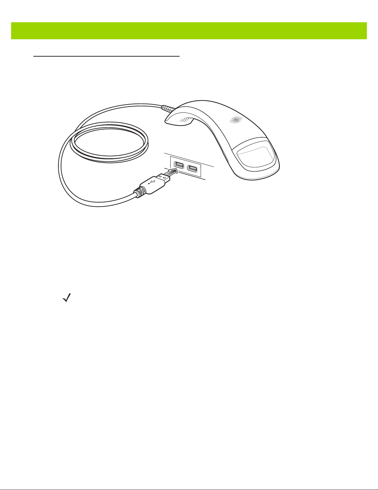
Host Connection
The DS4800 imager supports USB connection to a host. To connect the imager:
1. Plug the USB connector at the end of the cable into a USB port on the host.
Getting Started 1 - 3
Figure 1-2
2. The imager defaults to the HID keyboard interface type. To select another USB interface type, scan a
USB Device Type on page 3-3.
3. On first installation when using Windows, th e software prompts to select or install the Human Interface
Device driver. To install this driver, provided by Windows, click Next through all the choices and click
Finished on the last choice. The imager powers up during this installation.
If problems occur with the system, see Troubleshooting on page 12-3.
USB Host Connection
NOTE For a list of supported scanner functionality by USB protocol, see Appendix I, Communication Protocol
Functionality.
Page 24
1 - 4 DS4800 Series Corded Digital Imager Product Reference Guide
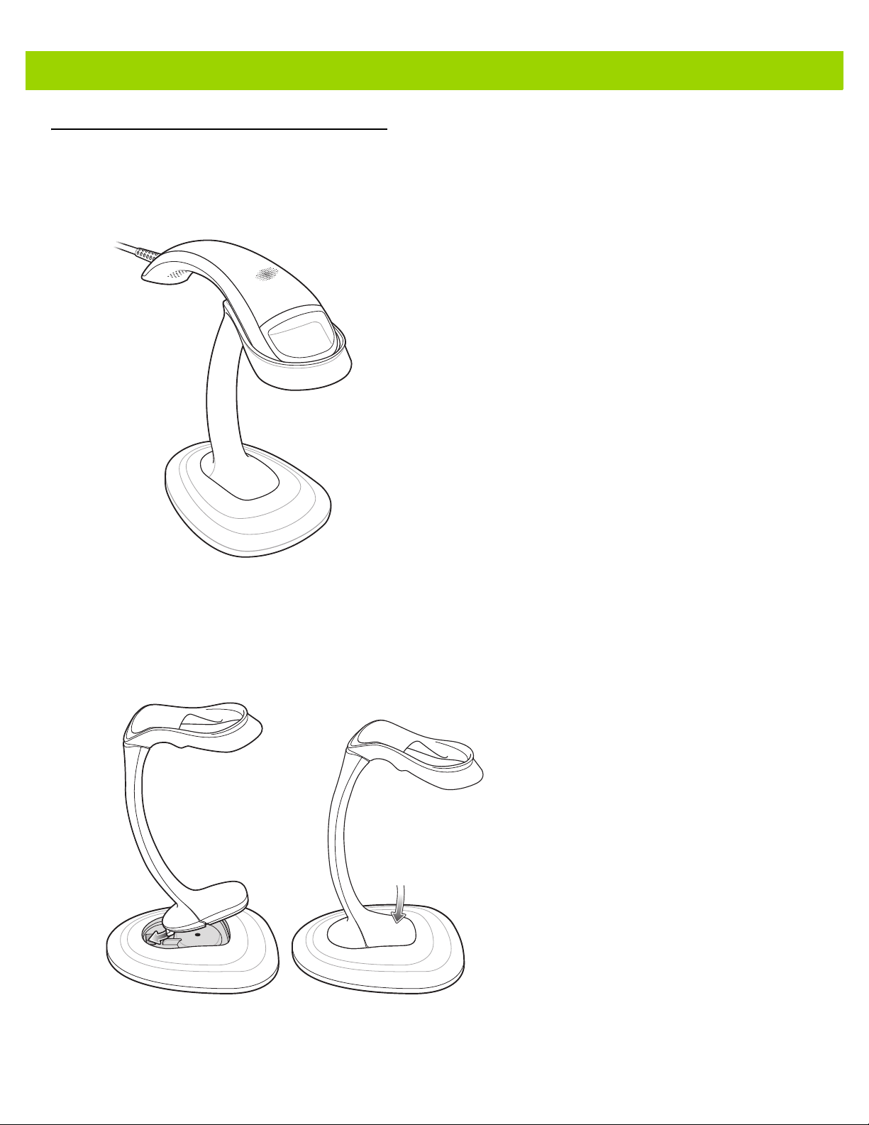
DS4800 Series Presentation Stand
An optional intellistand is available for using the imager in presentation mode. Placing the imager in the stand
automatically enables presentation mode, and a motion detection system rapidly wakes the imager from
timeout.
Figure 1-3
Presentation Intellistand
Assembling the Stand
To assemble the stand:
1. Insert the stand pedestal into the base as shown in Figure 1-4.
Figure 1-4
Inserting Stand Pedestal in Base
Page 25
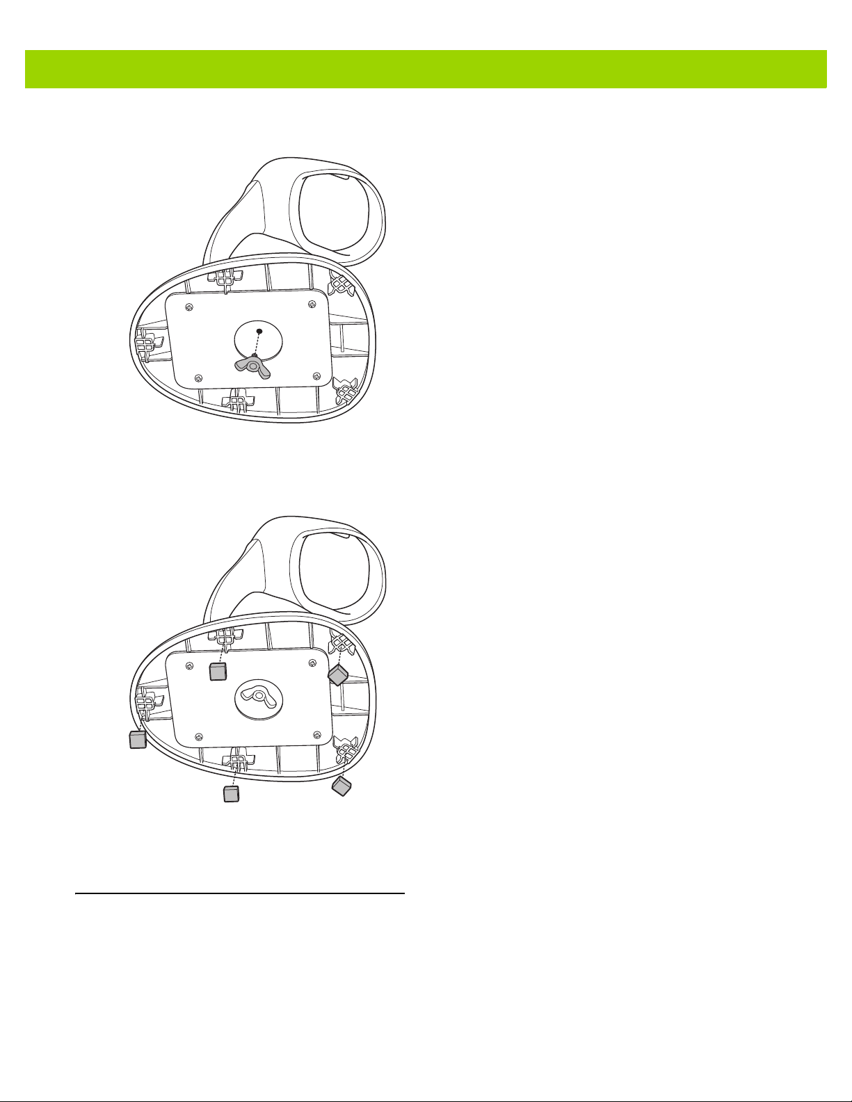
2. Screw the nut provided into the bottom of the base to secure.
Getting Started 1 - 5
Figure 1-5
3. Remove the adhesive from the rubber feet provided and secure them to the five recessed areas on the
bottom of the base.
Figure 1-6
Inserting Nut in Base
Inserting Rubber Feet
Configuring the Imager
To configure the imager use the bar codes included in this manual, or use the 123Scan2 configuration program.
See Chapter 10, 123Scan2 for information on using this configuration program.
Page 26

1 - 6 DS4800 Series Corded Digital Imager Product Reference Guide
Page 27

CHAPTER 2 DATA CAPTURE
Introduction
This chapter provides speaker and LED definitions, general scanning instructions and tips, and decode range
information.
User Feedback Definitions
The imager uses a 2-color indicator LED, a white trigger LED, various b eep sequences, and a vib rator motor to
indicate status. Table 2-1 defines the default beep sequences, LED displays, and vibration patterns that occur
during both normal scanning and while programming the imager.
Table 2-1
Standard Use
Power up. Power up tone Green, then fades out Double-
Ready to scan (hand-held mode). None None None
Ready to scan
(hands-free/presentation mode).
The trigger was touched. None None Vibrate for
A bar code was decoded. Wood block / scan
Transmission error. 4 long low tones Red None
Conversion or format error. 5 low tones Red None
Default User Feedback Definitions
Indication Speaker Sequence Indicator LED
None Pulsing green None
Green for 100 ms None
tone 1
Haptic/
Vibration
vibrate
100 ms
Page 28

2 - 2 DS4800 Series Corded Digital Imager Product Reference Guide
Table 2-1
Image Capture
Snapshot mode started. Low tone Green blinking None
Snapshot mode completed. Low tone Green (default based on
Snapshot mode timed-out. High, low tone Green (default based on
Parameter Programming
Input error: incorrect bar code,
programming sequence, or Cancel
bar code scanned.
Number expected. Enter value using
numeric bar codes.
Successful program exit with change
in parameter setting.
Default User Feedback Definitions (Continued)
Indication Speaker Sequence Indicator LED
hand-held (picklist) /
hands-free)
hand-held (picklist) /
hands-free)
Low, high tone Red for 2 seconds None
High, low tone Green None
High, low, high, low
tone
Green for 1 second None
None
None
Haptic/
Vibration
ADF Programming
Enter another digit. A dd leading zeros
to the front if necessary.
Enter another alphabetic character or
scan the End of Message bar code.
ADF criteria or action is expected.
Enter another criterion or action, or
scan the Save Rule bar code.
Rule saved. Rule entry mode exited. High, low, high, low
All criteria or actions cleared for
current rule, continue entering rule.
Delete last saved rule. The current
rule is left intact.
All rules are deleted. Low, high, high tone Green None
Out of rule memory. Erase some
existing rules, then try to save rule
again
Cancel rule entry. Rule entry mode
exited because of an error or the user
asked to exit rule entry.
High, low tone Green None
Low, low tone Green None
High, high tone Green Blinking None
Green (turns off blinking) None
tone
High, low, low tone Green None
Low tone Green None
Low, high, low, high
tone
Low, high, low tone Green (turns off blinking) None
Red None
Page 29

Data Capture 2 - 3
Table 2-1
Entry error , wrong bar code sc anned,
or criteria/action list is too long for a
rule. Re-enter criterion or action.
Macro PDF
File ID error. A bar code not in the
current MPDF sequence was
scanned.
File ID error. A bar code not in the
current MPDF sequence was
scanned.
Out of memory. There is not enough
buffer space to store the current
MPDF symbol.
Bad symbology. Scanned a 1D or 2D
bar code in a MPDF sequence, a
duplicate MPDF label, a label in an
incorrect order, or trying to transmit
an empty or illegal MPDF field.
Default User Feedback Definitions (Continued)
Indication Speaker Sequence Indicator LED
Haptic/
Vibration
Low, high tone Red None
2 low toned None None
2 long low tones None None
3 long low tones None None
4 long low tones None None
Flushing MPDF buffer. 5 long low tones None None
Aborting MPDF sequence. Fast warble tone None None
Flushing an already empty MPDF
buffer.
Low, high tone None None
Page 30
2 - 4 DS4800 Series Corded Digital Imager Product Reference Guide
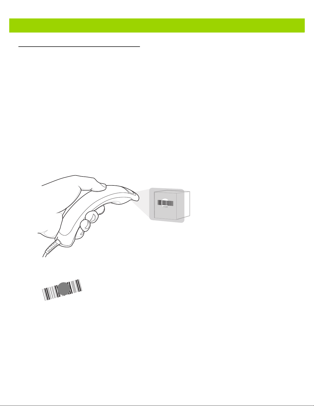
Scanning
The DS4800 can be used in either hand-held triggered mode, hand-held presentation mode, or hands-free
mode via an intellistand. To select the mode, see Hand-Held Triggered Mode on page 4-17.
Hand-Held Triggered Scanning
When held, the DS4800 operates in standard triggered mode. Initially, the trigger LED pulses in idle state.
To decode a bar co de :
1. Aim the imager at a bar code and touch the trigger to decode. Upon trigger touch:
•
The trigger LED turns off.
•
The imager vibrates for 100 ms (by default).
•
If enabled, a brief audio click sounds.
•
The imager projects illumination and a red LED aiming dot to facilitate positioning the bar code within its
field of view (see Table 12-2 on page 12-5 for the proper distance to achieve between the imager and a
bar code).
Figure 2-1
2. To scan the symbol, center the aiming dot on the symbol, in any orientation.
Figure 2-2
When a bar code is decoded:
3. Release the trigger. The trigger LED remains on while in an active state (10 seconds after the last trigger
press), then returns to idle state and pulses.
Scanning in Hand-Held Mode
Scanning Orientation with Imager Aiming Dot
• A tone sounds (by default). To change the tone, see Scan Tone on page 4-10.
To disable the tone, see Beep After Good Decode on page 4-7.
• The green indicator LED turns on (by default). To disable this, see LED on Good Decode on page
4-12.
• If enabled, the imager provides haptic feedback. See Haptic Feedback (Vibrate) on Good Decode on
page 4-13.
Page 31
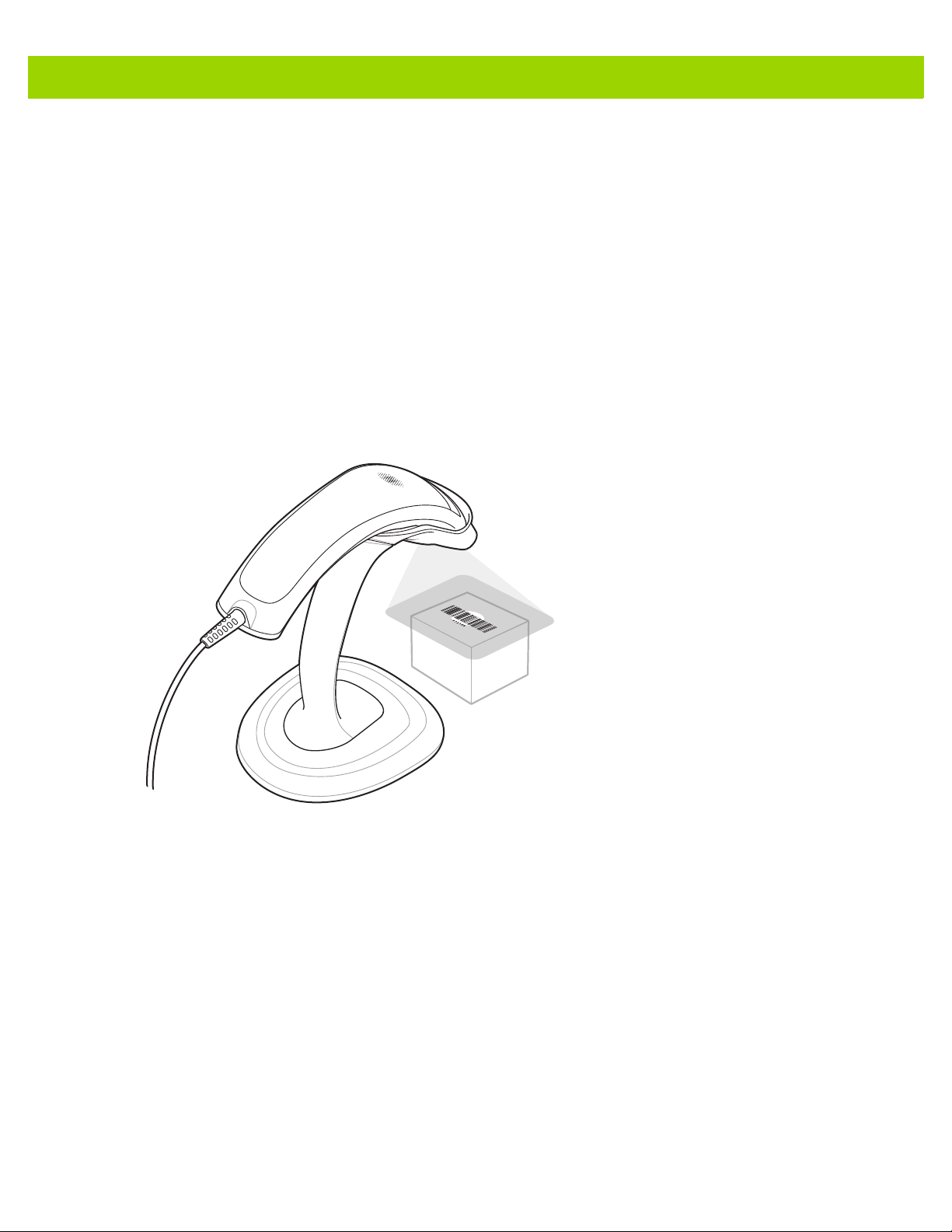
Data Capture 2 - 5
Hands-Free Presentation Scanning
When placed in the presentation intellistand, the imager automatically enters hands-free presentation mode.
Initially in this mode:
•
Illumination is off.
•
The white trigger LED is off.
•
The green indicator LED continuously pulses.
Present a bar code to the imager or swipe the bar code past the exit window:
•
Illumination turns on.
•
Optionally, the aiming dot turns on if enabled via Hands-Free Decode Aiming Pattern on page 4-19.
•
The green indicator LED turns off.
Figure 2-3
When a bar code is decoded:
•
•
•
Hands-Free Presentation Scanning
A tone sounds (by default). To change the tone, see Scan Tone on page 4-10.
To disable the tone, see Beep After Good Decode on page 4-7.
The green indicator LED turns on momentarily (by default), then returns to idle state and pulses. To
disable this, see LED on Good Decode on page 4-12.
Haptic feedback does not occur, even if enabled in hand-held mode.
Page 32

2 - 6 DS4800 Series Corded Digital Imager Product Reference Guide
Hand-Held Presentation Scanning
This mode is disabled by default. Initially in this mode:
•
The aiming dot and illumination are off.
•
The white trigger LED is off.
•
The green indicator LED continuously pulses.
When lifted off the counter or removed from the presentation intellistand:
•
The DS4800 detects motion and turns illumination on.
•
Optionally, the aiming dot turns on if enabled via Hands-Free Decode Aiming Pattern on page 4-19.
•
The green indicator LED turns off.
Aim the imager at a bar code to activate decode processing.
Figure 2-4
When a bar code is decoded:
•
•
•
Hand-Held Presentation Scanning
A tone sounds (by default). To change the tone, see Scan Tone on page 4-10.
To disable the tone, see Beep After Good Decode on page 4-7.
The green indicator LED turns on momentarily (by default), then returns to idle state and pulses. To
disable this, see LED on Good Decode on page 4-12.
If enabled, the imager provides haptic feedback. See Haptic Feedback (Vibrate) on Good Decode on
page 4-13.
Page 33

CHAPTER 3 USB INTERFACE
*Enable Keypad Emulation
Feature/Option
*Indicates Default
Introduction
This chapter describes how to set up the imager with a USB host. The imager connects directly to a USB host,
or a powered USB hub, which powers it. No additional power supply is required.
NOTE For a list of supported scanner functionality by communication protocol, see Appendix I, Communication
Protocol Functionality.
Throughout the programming bar code menus, aste risks (
NOTE Most computer monitors allow scanning the bar codes directly on the screen. When scanning from the
screen, be sure to set the document magnification to a level where you can see the bar code clearly, and
bars and/or spaces are not merging.
*) indicate default values.
Page 34

3 - 2 DS4800 Series Corded Digital Imager Product Reference Guide
USB Parameter Defaults
Table 3-1 lists the defaults for USB host parameters. To change any option, scan the appropriate bar code(s)
provided in this chapter.
NOTE See Appendix A, Standard Default Parameters for all user preferences, symbologies, and miscellaneous
default parameters.
Table 3-1
USB Host Parameters
USB Device Type USB Keyboard HID
Symbol Native API (SNAPI) Status Handshak ing Enable
USB Keystroke Delay No Delay
USB CAPS Lock Override Disable
USB Ignore Unknown Characters Enable
USB Convert Unknown to Code 39 Disable
Emulate Keypad Enable
Emulate Keypad with Leading Zero Enable
Quick Keypad Emulation Enable
USB FN1 Substitution Disable
Function Key Mapping Disable
Simulated Caps Lock Disable
USB Interface Parameter Defaults
Parameter Default
Page
Number
3-3
3-5
3-5
3-6
3-6
3-7
3-7
3-8
3-8
3-9
3-9
3-10
Convert Case None
USB Polling Interval 3 msec
USB Fast HID Enable
USB Static CDC Enable
Direct I/O Beep Ignore
Beep Directive Ignore
Bar Code Configuration Directive Ignore
IBM Specification Version Original Specification
3-10
3-11
3-12
3-13
3-13
3-14
3-14
3-15
Page 35

USB Host Parameters
USB Device Type
Select the desired USB device type. To select a country keyboard type for the USB Keyboard HID host, see
Appendix B, Country Codes.
NOTE When changing USB Device Types, the imager automatically resets and issues the standard startup beep
sequences.
NOTE Select IBM Hand-Held USB to disable data transmission when an IBM register issues a Scan Disable
command. Aim, illumination, and decoding is still permitted. Select IBM OPOS (IBM Hand-Held USB with
Full Scan Disable) to completely shut off the imager when an IBM register issues a Scan Disable
command, including aim, illumination, decoding and data transmission.
USB Interface 3 - 3
*
USB Keyboard HID
IBM Hand-Held USB
IBM Ta bl e-Top USB
IBM OPOS
(IBM Hand-Held USB with Full Scan Disable)
Simple COM Port Emulation
Page 36

3 - 4 DS4800 Series Corded Digital Imager Product Reference Guide
USB Device Type (continued)
SSI over USB CDC
USB CDC Host
(Note)
Symbol Native API (SNAPI) without Imaging Interface
NOTE Before selecting USB CDC Host, install the CDC INF file on the host to ensure the imager does not stall
during power up (due to a failure to enumerate USB). If the imager stalls, to recover it:
1
. Install the CDC INF file
or
2. After power-up, hold the trigger for 10 seconds, which allows the imager to power up using
an
alternate USB configuration. Upon power-up, scan another USB Device Type.
Symbol Native API (SNAPI) with Imaging Interface
Page 37

USB Interface 3 - 5
Symbol Native API (SNAPI) Status Handshaking
After selecting a SNAPI interface as the USB device type, select whether to enable or disable status
handshaking.
*Enable SNAPI Status Handshaking
Disable SNAPI Status Handshaking
USB Keystroke Delay
This parameter sets the delay, in milliseconds, between emulated keystrokes. Scan a bar code below to
increase the delay when hosts require a slower transmission of data.
*No Delay
Medium Delay (20 msec)
Long Delay (40 msec)
Page 38

3 - 6 DS4800 Series Corded Digital Imager Product Reference Guide
USB CAPS Lock Override
This option applies only to the
regardless of the state of the Caps Lock key. This setting is always enabled for the Japanese, Windows
(ASCII) keyboard type and can not be disabled.
Override Caps Lock Key
(Enable)
USB Keyboard HID
device. Enable this to preserve the case of the data
*Do Not Override Caps Lock Key
(Disable)
USB Ignore Unknown Characters
This option applies only to the
the host does not recognize. Select Send Bar Codes With Unknown Characters to send all bar code data
except for unknown characters. The imager issues no error beeps.
USB Keyboard HID
device and IBM device. Unknown characters are characters
Select Do Not Send Bar Codes With Unknown Characters, for IBM devices, to prevent sending bar codes
containing at least one unknown character are to the host, or for
code characters up to the unknown character. The imager issues an error beep.
USB Keyboard HID
devices, this sends the bar
*Send Bar Codes with Unknown Characters
(Transmit)
Do Not Send Bar Codes with Unknown Characters
(Disable)
Page 39

USB Interface 3 - 7
USB Convert Unknown to Code 39
This option applies only to the IBM hand-held, IBM table-top, and OPOS devices. Scan a bar code below to
enable or disable converting unknown bar code type data to Code 39.
*Disable Convert Unknown to Code 39
Enable Convert Unknown to Code 39
Emulate Keypad
Enable this to send all characters as ASCII sequences over the numeric keypad. For example ASCII A
transmits as “ALT make” 0 6 5 “ALT Break”.
*Enable Keypad Emulation
Disable Keypad Emulation
Page 40

3 - 8 DS4800 Series Corded Digital Imager Product Reference Guide
Emulate Keypad with Leading Zero
Enable this to send character sequences sent over the numeric keypad as ISO characters which have a
leading zero. For example ASCII A transmits as “ALT MAKE” 0 0 6 5 “ALT BREAK”.
*Enable Keypad Emulation with Leading Zero
Disable Keypad Emulation with Leading Zero
Quick Keypad Emulation
This option applies only to the
parameter enables a quicker method of emulation using the n umeric keypad wher e ASCII sequences are only
sent for ASCII characters not found on the keyboard. The default value is Enable.
USB Keyboard HID
device when Emulate Keypad on page 3-7 is enabled. This
*Enable Quick Keypad Emulation
Disable Quick Keypad Emulation
Page 41

USB Keyboard FN 1 Substitution
USB Interface 3 - 9
This option applies only to the
128 bar code with a user-selected Key Category and value (see FN1 Substitution Values on page 4-34 to set
the Key Category and Key Value).
Enable USB Keyboard FN 1 Substitution
USB Keyboard HID
device. Enable this to replace any FN 1 characters in a GS1
*Disable USB Keyboard FN 1 Substitution
Function Key Mapping
ASCII values under 32 are normally sent as a control-key sequences (s ee Table 3-2 on page 3-16). Enable this
parameter to send the keys in bold in place of the standard key mapping. Table entries that do not have a bold
entry remain the same whether or not you enable this parameter.
*Disable Function Key Mapping
Enable Function Key Mapping
Page 42

3 - 10 DS4800 Series Corded Digital Imager Product Reference Guide
Simulated Caps Lock
Enable this to invert upper and lower case characters on the bar code as if the Caps Lock state is enabled on
the keyboard. This inversion occurs regardless of the keyboard’s Caps Lock state.
NOTE Simulated Caps Lock applies to ASCII characters only.
*Disable Simulated Caps Lock
Convert Case
Enable this to convert all bar code data to the selected case.
NOTE Convert Case applies to ASCII characters only.
*No Case Conversion
Enable Simulated Caps Lock
Convert All to Upper Case
Convert All to Lower Case
Page 43

USB Interface 3 - 11
USB Polling Interval
Scan a bar code below to set the polling interval. The polling interval is the rate at which data transmits
between the imager and host computer. A lower number indicates a faster data rate.
NOTE When changing the USB polling interval, the imager restarts and issues a power-up beep sequence.
IMPORTANT Ensure the host supports the selected data rate.
1 msec
* 3 msec
5 msec
2 msec
4 msec
Page 44

3 - 12 DS4800 Series Corded Digital Imager Product Reference Guide
USB Polling Interval (continued)
6 msec
7 msec
USB Fast HID
This option transmits
8 msec
USB HID
*Enable
9 msec
data at a faster rate.
Disable
Page 45

USB Static CDC
When disabled, each device connected consumes another COM port (first device = COM1,
second device = COM2, third device = COM3, etc.)
When enabled, each device connects to the same COM port.
*Enable USB Static CDC
Disable USB Static CDC
USB Interface 3 - 13
Direct I/O Beep
The host can send a direct I/O beep request to the imager. If you select Ignore Direct I/O Beep, the imager
does not sound beeps on this command. All directives are still acknowledged to the USB host as if they were
processed.
Honor Direct IO Beep
*Ignore Direct IO Beep
Page 46

3 - 14 DS4800 Series Corded Digital Imager Product Reference Guide
Beep Directive
The host can send a beeper configuration request to the imager. Scan Ignore Beep Directive to prevent the
imager from processing the host request. All directives are still acknowledged to the USB host as if they were
processed.
Honor Beep Directive
*Ignore Beep Directive
Bar Code Configuration Directive
The host can enable and disable code types. Scan Ignore Bar Code Configuration Directive to prevent the
imager from processing the host request. All directives are still acknowledged to the USB host as if they were
processed.
Honor Bar Code Configuration Directive
*Ignore Bar Code Configuration Directive
Page 47

USB Interface 3 - 15
IBM Specification Version
The IBM USB interface specification version selected defines how code types are reported over the IBM USB
interface.
* Original Specification
Version 2.2
Page 48

3 - 16 DS4800 Series Corded Digital Imager Product Reference Guide
ASCII Character Set for USB
Table 3-2
Prefix/ Suffix Value
USB Prefix/Suffix Values
Full ASCII Code 39
Encode Char.acter
1000 %U CTRL 2
1001 $A CTRL A
1002 $B CTRL B
1003 $C CTRL C
1004 $D CTRL D
1005 $E CTRL E
1006 $F CTRL F
1007 $G CTRL G
1008 $H
1009 $I
CTRL H/
CTRL I/
1010 $J CTRL J
1011 $K CTRL K
Keystroke
BACKSPACE
1
HORIZONTAL TAB
1
1012 $L CTRL L
1013 $M
CTRL M/
1014 $N CTRL N
1015 $O CTRL O
1016 $P CTRL P
1017 $Q CTRL Q
1018 $R CTRL R
1019 $S CTRL S
1020 $T CTRL T
1021 $U CTRL U
1022 $V CTRL V
1023 $W CTRL W
1024 $X CTRL X
1025 $Y CTRL Y
1
The keystroke in bold transmits only if you enable
3-9
. Otherwise, the unbolded keystroke transmits.
Function Key Mapping on page
ENTER
1
Page 49

USB Interface 3 - 17
Table 3-2
Prefix/ Suffix Value
USB Prefix/Suffix Values (Continued)
Full ASCII Code 39
Encode Char.acter
1026 $Z CTRL Z
1027 %A
CTRL [/
1028 %B CTRL \
1029 %C CTRL ]
1030 %D CTRL 6
1031 %E CTRL 1032 Space Space
1033 /A !
1034 /B “
1035 /C #
1036 /D $
1037 /E %
Keystroke
1
ESC
1038 /F &
1039 /G ‘
1040 /H (
1041 /I )
1042 /J *
1043 /K +
1044 /L ,
1045 - 1046 . .
1047 /O /
1048 0 0
1049 1 1
1050 2 2
1051 3 3
1052 4 4
1053 5 5
1054 6 6
1
The keystroke in bold transmits only if you enable
3-9
. Otherwise, the unbolded keystroke transmits.
Function Key Mapping on page
Page 50

3 - 18 DS4800 Series Corded Digital Imager Product Reference Guide
Table 3-2
Prefix/ Suffix Value
USB Prefix/Suffix Values (Continued)
Full ASCII Code 39
Encode Char.acter
1055 7 7
1056 8 8
1057 9 9
1058 /Z :
1059 %F ;
1060 %G <
1061 %H =
1062 %I >
1063 %J ?
1064 %V @
1065 A A
1066 B B
1067 C C
Keystroke
1068 D D
1069 E E
1070 F F
1071 G G
1072 H H
1073 I I
1074 J J
1075 K K
1076 L L
1077 M M
1078 N N
1079 O O
1080 P P
1081 Q Q
1082 R R
1083 S S
1
The keystroke in bold transmits only if you enable
. Otherwise, the unbolded keystroke transmits.
3-9
Function Key Mapping on page
Page 51

USB Interface 3 - 19
Table 3-2
Prefix/ Suffix Value
USB Prefix/Suffix Values (Continued)
Full ASCII Code 39
Encode Char.acter
1084 T T
1085 U U
1086 V V
1087 W W
1088 X X
1089 Y Y
1090 Z Z
1091 %K [
1092 %L \
1093 %M ]
1094 %N ^
1095 %O _
1096 %W `
Keystroke
1097 +A a
1098 +B b
1099 +C c
1100 +D d
1101 +E e
1102 +F f
1103 +G g
1104 +H h
1105 +I i
1106 +J j
1107 +K k
1108 +L l
1109 +M m
1110 +N n
1111 +O o
1112 +P p
1
The keystroke in bold transmits only if you enable
. Otherwise, the unbolded keystroke transmits.
3-9
Function Key Mapping on page
Page 52

3 - 20 DS4800 Series Corded Digital Imager Product Reference Guide
Table 3-2
Prefix/ Suffix Value
USB Prefix/Suffix Values (Continued)
Full ASCII Code 39
Encode Char.acter
1113 +Q q
1114 +R r
1115 +S s
1116 +T t
1117 +U u
1118 +V v
1119 +W w
1120 +X x
1121 +Y y
1122 +Z z
1123 %P {
1124 %Q |
1125 %R }
Keystroke
1126 %S ~
1
The keystroke in bold transmits only if you enable
3-9
. Otherwise, the unbolded keystroke transmits.
Function Key Mapping on page
Page 53

USB Interface 3 - 21
Table 3-3
2064 ALT 2
2065 AL T A
2066 ALT B
2067 ALT C
2068 ALT D
2069 ALT E
2070 ALT F
2071 ALT G
2072 ALT H
2073 ALT I
2074 ALT J
2075 ALT K
2076 ALT L
USB ALT Key Character Set
ALT Keys Keystroke
2077 ALT M
2078 ALT N
2079 ALT O
2080 ALT P
2081 ALT Q
2082 ALT R
2083 ALT S
2084 AL T T
2085 ALT U
2086 ALT V
2087 ALT W
2088 ALT X
2089 AL T Y
2090 ALT Z
Page 54

3 - 22 DS4800 Series Corded Digital Imager Product Reference Guide
Table 3-4
3000 Right Control Key
3048 GUI 0
3049 GUI 1
3050 GUI 2
3051 GUI 3
3052 GUI 4
3053 GUI 5
3054 GUI 6
3055 GUI 7
3056 GUI 8
3057 GUI 9
3065 GUI A
3066 GUI B
USB GUI Key Character Set
GUI Key Keystroke
3067 GUI C
3068 GUI D
3069 GUI E
3070 GUI F
3071 GUI G
3072 GUI H
3073 GUI I
3074 GUI J
3075 GUI K
3076 GUI L
3077 GUI M
3078 GUI N
3079 GUI O
3080 GUI P
3081 GUI Q
Note: GUI Shift Keys - The Apple™ iMac keyboard has
an apple key on either side of the space bar.
Windows-based systems have a GUI key to the left of
the left ALT key, and to the right of the right ALT key.
Page 55

USB Interface 3 - 23
Table 3-4
3082 GUI R
3083 GUI S
3084 GUI T
3085 GUI U
3086 GUI V
3087 GUI W
3088 GUI X
3089 GUI Y
3090 GUI Z
Note: GUI Shift Keys - The Apple™ iMac keyboard has
an apple key on either side of the space bar.
Windows-based systems have a GUI key to the left of
the left ALT key, and to the right of the right ALT key.
USB GUI Key Character Set (Continued)
GUI Key Keystroke
Page 56

3 - 24 DS4800 Series Corded Digital Imager Product Reference Guide
Table 3-5
5001 F1
5002 F2
5003 F3
5004 F4
5005 F5
5006 F6
5007 F7
5008 F8
5009 F9
5010 F10
5011 F11
5012 F12
5013 F13
USB F Key Character Set
F Keys Keystroke
5014 F14
5015 F15
5016 F16
5017 F17
5018 F18
5019 F19
5020 F20
5021 F21
5022 F22
5023 F23
5024 F24
Page 57

USB Interface 3 - 25
Table 3-6
6042 *
6043 +
6044 undefined
6045 6046 .
6047 /
6048 0
6049 1
6050 2
6051 3
6052 4
6053 5
6054 6
USB Numeric Keypad Character Set
Numeric Keypad Keystroke
6055 7
6056 8
6057 9
6058 Enter
6059 Num Lock
Page 58

3 - 26 DS4800 Series Corded Digital Imager Product Reference Guide
Table 3-7
7001 Break
7002 Delete
7003 PgUp
7004 End
7005 Pg Dn
7006 Pause
7007 Scroll Lock
7008 Backspace
7009 Tab
7010 Print Screen
7011 Insert
7012 Home
7013 Enter
USB Extended Keypad Character Set
Extended Keypad Keystroke
7014 Escape
7015 Up Arrow
7016 Down Arrow
7017 Left Arrow
7018 Right Arrow
Page 59

CHAPTER 4 USER PREFERENCES &
*High Volume
(0)
Feature/Option
* Indicates Default
Option Value
MISCELLANEOUS OPTIONS
Introduction
Y o u can program the imager to perfor m various functions, or activate dif ferent fe atures. This chap ter describe s
each user preference feature and provides programming bar codes for selecting these features.
The imager ships with the settings shown in Table 4-2 on page 4-3 (also see Appendix A, Standard Default
Parameters for all imager defaults). If the default values suit requirements, programming is not necessary.
To set feature values, scan a single bar code or a short bar code sequence. The settings are stored in
non-volatile memory and are preserved even when the imager is powered down.
NOTE Most computer monitors allow scanning the bar codes directly on the screen. When scanning from the
screen, be sure to set the document magnification to a level where you can see the bar code clearly, and
bars and/or spaces are not merging.
To return all features to default values, see Default Parameters on page 4-5. Throughout the programming bar
code menus, asterisks indicate (
*) default values.
Page 60

4 - 2 DS4800 Series Corded Digital Imager Product Reference Guide
User Experience
DS4800 Series imagers offer user-friendly fe atur es that e nhance the de codin g expe rience. Table 4-1 provides
a quick reference for selecting these triggering and decoding features.
Table 4-1
Trigger Definitions
Tone / Audio Click 1252 On / Off*
Haptic 1251 On* / Off
Good Decode Feedback Definitions
Tone / Beep 56 On* / Off
Scan T one Selection 145 Tones 1* - 6, Low,
Haptic 613 On / Off*
Indicator LED 744 On* / Off
* indicates the default value.
User Experience Options
Feature
Scanning Sequence Examples
Parameter
Number
Options
Medium, High
Page
Number
4-16
4-16
4-7
4-10
4-13
4-12
In most cases, scanning one bar code sets the parameter value. For example, to set the speaker volume to
low, scan the Low Volume bar code listed under Speaker Volume on page 4-9. The imager issues a fast
warble beep and the LED turns green, signifying a successful parameter entry.
Other parameters, such as Serial Response Time-Out or Data Transmission Formats, require scanning
several bar codes. See these parameter descriptions for this procedure.
Errors While Scanning
Unless otherwise specified, to correct an error during a scanning sequence, just re-scan the correct parameter.
User Preferences/Miscellaneous Options Parameter Defaults
Table 4-2 lists defaults for user preferences parameters. To change the default values:
•
Scan the appropriate bar codes in this guide. These new values replace the standard default values in
memory. To recall the default parameter values, see Default Parameters on page 4-5.
•
Configure the imager using the 123Scan2 configuration program (see 123Scan2 on page 10-1).
NOTE See Appendix A, Standard Default Parameters for all user preferences, hosts, symbologies, and
miscellaneous default parameters.
Page 61

User Preferences & Miscellaneous Options 4 - 3
Table 4-2
User Preferences
Set Default Parameter Restore Defaults
Report Version N/A
Parameter Bar Code Scanning 236 Enable
Beep After Good Decode 56 Enable
Direct Decode Indicator 859 Disable
Speaker Volume 140 High
Scan Tone 145 Wood Block / Scan Tone 1
Suppress Power Up Beeps 721 Do Not Suppress
LED on Good Decode 744 Enable
Haptic Feedback (Vibrate) on Good Decode 613 Disable
Haptic Feedback (Vibrate) on Good Decode
Duration
User Preferences Parameter Defaults
Parameter
Parameter
Number
626 100 msec
Default
Page
Number
4-5
4-6
4-6
4-7
4-8
4-9
4-10
4-12
4-12
4-13
4-14
Haptic Feedback (Vibrate) on Trigger Touch 1251 Enable
Tone on Trigger Touch 1252 Disable
Hand-Held Triggered Mode 138 Auto Aim
Hand-Held Decode Aiming Pattern 306 Enable
Hands-Free (Presentation) Decode Aiming
Pattern
Picklist Mode 402 Disabled Always
Continuous Bar Code Read 649 Disable
Unique Bar Code Reporting 723 Enable
Decode Session Timeout 136 9.9 Sec
Timeout Between Decodes, Same Symbol 137 0.5 Sec
Timeout Between Decodes, Different
Symbols
Fuzzy 1D Processing 514 Enable
Decode Mirror Images (Data Matrix Only) 537 Auto
590 Enable Hands-Free
(Presentation) Decode Aiming
Pattern on PDF
144 0.1 sec
4-16
4-16
4-17
4-18
4-19
4-20
4-21
4-21
4-22
4-22
4-23
4-23
4-24
Mobile Phone/Display Mode 716 Normal
PDF Prioritization 719 Disable
PDF Prioritization Timeout 720 200 ms
4-25
4-26
4-26
Page 62

4 - 4 DS4800 Series Corded Digital Imager Product Reference Guide
Table 4-2
Presentation Mode Field of View 609 Full
Decoding Illumination 298 Enable
Low Light Scene Detection 810 Aiming Dot Low Light Assist
Motion Tolerance (Hand-Held Triggered
Mode Only)
Miscellaneous Options
Transmit Code ID Character 45 None
Prefix Value 99, 105 7013 <CR><LF>
Suffix 1 Value
Suffix 2 Value
Scan Data Transmission Format 235 Data as is
FN1 Substitution Values 103, 109 7013 <CR><LF>
Transmit “No Read” Message 94 Disable
User Preferences Parameter Defaults (Continued)
Parameter
Parameter
Number
858 Less Motion Tolerance
98, 104
100, 106
Default
Scene Detection
7013 <CR><LF>
Page
Number
4-27
4-28
4-29
4-30
4-31
4-32
4-32
4-33
4-34
4-35
Unsolicited Heartbeat Interval 1118 Disable
4-36
Page 63

User Preferences
Default Parameters
The imager can be reset to two types of defaults: factory defaults or custom defaults. Scan the appro priate bar
code below to reset the imager to its default settings and/or set the imager’s current settings as the custom
default.
•
Restore Defaults - Resets all default parameters as follows:
• If custom default values were configured (see Write to Custom Defaults), the custom default values
are set for all parameters each time the Restore Defaults bar code below is scanned.
• If no custom default values were configured, the factory default values are se t for all parame ters each
time the Restore Defaults bar code below is scanned. (For factory default values, see Appendix A,
Standard Default Parameters.)
•
Set Factory Defaults - Scan the Set Factory Defaults bar code below to eliminate all custom default
values and set the imager to factory default values (For factory default values, see Appendix A, Standard
Default Parameters).
•
Write to Custom Defaults - Custom default parameters can be configured to set unique default values
for all parameters. After changing al l parameters to the desired default values, scan the W rite to Custom
Defaults bar code below to configure custom defaults.
User Preferences & Miscellaneous Options 4 - 5
*Restore Defaults
Write to Custom Defaults
Set Factory Defaults
Page 64

4 - 6 DS4800 Series Corded Digital Imager Product Reference Guide
Report Version
Scan the bar code below to report the version of software installed in the imager.
Report Software Version
Parameter Bar Code Scanning
Parameter # 236
To disable the decoding of parameter bar codes, including the Set Defaults parameter bar codes, scan the
Disable Parameter Scanning bar code below. To enable decoding of parameter bar codes, scan Enable
Parameter Scanning.
*Enable Parameter Bar Code Scanning
(1)
Disable Parameter Bar Code Scanning
(0)
Page 65

User Preferences & Miscellaneous Options 4 - 7
Beep After Good Decode
Parameter # 56
Scan a bar code below to select whether or not the imager beeps after a good decode. If selecting Do Not
Beep After Good Decode, the speaker still operates during parameter menu scanning and to indicate error
conditions.
*Beep After Good Decode
(Enable)
(1)
Do Not Beep After Good Decode
(Disable)
(0)
Page 66

4 - 8 DS4800 Series Corded Digital Imager Product Reference Guide
Direct Decode Indicator
Parameter # 859
This feature is only supported in Auto Aim and Standard (Level) trigger modes. Scan a bar code below to
select optional blinking of the illumination upon a successful decode if you continue to hold the trigger. If you
release the trigger upon decode, the blinking does no t occur. This allows you to choose additional feedback for
a successful decode by holding the trigger, or to continue to scan as normal.
Options are:
•
Disable Direct Decode Indicator - illumination does not blink on a successful decode.
•
1 Blink - illumination blinks once upon a successful decode.
•
2 Blinks - illumination blinks twice upon a successful decode.
*Disable Direct Decode Indicator
(0)
2 Blinks
(2)
1 Blink
(1)
Page 67

User Preferences & Miscellaneous Options 4 - 9
Speaker Volume
Parameter # 140
To select a speaker volume, scan the Low Volume, Medium Volume, or High Volume bar code.
Low Volume
(2)
Medium Volume
(1)
*High Volume
(0)
Page 68

4 - 10 DS4800 Series Corded Digital Imager Product Reference Guide
Scan Tone
Parameter # 145
To select a scan tone, scan one of the following bar codes. Select from the special tones below, or from the
standard low, medium, and high tones.
*Wood Block / Tone 1
(6)
Pulse / Tone 2
(7)
Chime / Tone 3
(8)
Triple Beep / Tone 5
(10)
Zap / Tone 4
(9)
User Programmable / Tone 6
(11)
Note: See Custom Scan T o ne on page K-1 to download a
custom tone.
Page 69

Standard Tones
User Preferences & Miscellaneous Options 4 - 11
Low Tone
(2)
Medium Tone
(1)
High Tone
(0)
Page 70

4 - 12 DS4800 Series Corded Digital Imager Product Reference Guide
Suppress Power Up Beeps
Parameter # 721
Scan a bar code below to select whether or not to suppress imager beeps upon power up.
*Do Not Suppress Power Up Beeps
(0)
Suppress Power Up Beeps
(1)
LED on Good Decode
Parameter # 744
Scan a bar code below to select whether or not the imager LED blinks on a good decode.
*Enable LED on Good Decode
(3)
Disable LED on Good Decode
(4)
Page 71

User Preferences & Miscellaneous Options 4 - 13
Haptic Feedback (Vibrate) on Good Decode
Parameter # 613
The imager provides haptic feedback which, when enabled, vibrates the imager for a period of time when a
successful decode occurs.
Scan a bar code below to enable or disable Haptic Feedback (Vibrate) on Good Decode. If enabled, scan the
appropriate bar code for the Haptic Feedback (Vibrate) on Good Decode Duration to set the period of time in
which to vibrate the imager.
NOTE If you enable this parameter, in order to best distinguish between haptic feedback indications, either
disable Haptic Feedback (Vibrate) on Trigger Touch on page 4-16 or set a longer Haptic Feedback
(Vibrate) on Good Decode Duration.
*Disable Haptic Feedback (Vibrate) on Good Decode
(0)
Enable Haptic Feedback (Vibrate) on Good Decode
(1)
Page 72

4 - 14 DS4800 Series Corded Digital Imager Product Reference Guide
Haptic Feedback (Vibrate) on Good Decode Duration
Parameter # 626
*100 msec
(10)
150 msec
(15)
200 msec
(20)
300 msec
(30)
250 msec
(25)
Page 73

User Preferences & Miscellaneous Options 4 - 15
Haptic Feedback (Vibrate) on Good Decode Duration (continued)
400 msec
(40)
500 msec
(50)
600 msec
(60)
750 msec
(75)
Page 74

4 - 16 DS4800 Series Corded Digital Imager Product Reference Guide
Haptic Feedback (Vibrate) on Trigger Touch
Parameter # 1251
The imager provides haptic feedback which, when enabled, vibrates the imager upon a trigger touch.
Scan a bar code below to enable or disable this feature.
*Enable Haptic Feedback (Vibrate) on Trigger Touch
(1)
Disable Haptic Feedback (Vibrate) on Trigger Touch
(0)
Tone on Trigger Touch
Parameter # 1252
Scan a bar code below to enable or disable a tone upon a trigger touch.
NOTE To ensure the aiming dot appears during scanning, disable this feature if you enabled Picklist Mode on
page 4-20 or Hand-Held Decode Aiming Pattern on page 4-18.
*Disable Tone on Trigger Touch
(0)
Enable Tone on Trigger Touch
(1)
Page 75

Hand-Held Triggered Mode
Parameter # 138
Select one of the following triggered modes for the imager.
•
Standard (Level) - A trigger touch activates decode processing. Decode processing continues until the
bar code decodes, you release the trigger, or the Decode Session Timeout on page 4-22 occurs.
•
Presentation (Blink) - The imager activates decod e processing when it detects a bar code in its field of
view. After a period of non-use, the imager enters a low power mode, in which the LEDs turn off until the
imager senses motion.
•
Auto Aim - This triggered mode projects the aiming dot when you lift the imager. A trigger touch activates
decode processing. After 2 seconds of inactivity the aiming dot shuts off.
Level (Standard)
(0)
User Preferences & Miscellaneous Options 4 - 17
* Auto Aim
(9)
Presentation (Blink)
(7)
Page 76

4 - 18 DS4800 Series Corded Digital Imager Product Reference Guide
Hand-Held Decode Aiming Pattern
Parameter # 306
Select Enable Hand-Held Decode Aiming Pattern to project the aiming dot during bar code capture, Disable
Hand-Held Decode Aiming Pattern to turn the aiming dot off, or Enable Hand-Held Decode Aiming Pattern
on PDF to project the aiming dot when the imager detects a 2D bar code.
NOTE To ensure the aiming dot appears during scanning, disable T one on Trigger Touch on page 4-16 if using
this feature.
NOTE With Picklist Mode on page 4-20 enabled, the decode aiming dot flashes even when the Hand-Held
Decode Aiming Pattern is disabled.
*Enable Hand-Held Decode Aiming Pattern
(2)
Enable Hand-Held Decode Aiming Pattern on PDF
(3)
Disable Hand-Held Decode Aiming Pattern
(0)
Page 77

User Preferences & Miscellaneous Options 4 - 19
Hands-Free Decode Aiming Pattern
Parameter # 590
Select Enable Hands-Free Decode Aiming Pattern to project the aiming dot during bar code capture,
Disable Hands-Free Decode Aiming Pattern to turn the aiming dot off, or Enable Hands-Free Decode
Aiming Pattern on PDF to project the aiming dot when the imager detects a 2D bar code.
NOTE With Picklist Mode on page 4-20 enabled, the decode aiming dot flashes even when the Decode Aiming
Pattern is disabled.
Enable Hands-Free Decode Aiming Pattern
(1)
*Enable Hands-Free Decode Aiming Pattern on PDF
(2)
Disable Hands-Free Decode Aiming Pattern
(0)
Page 78

4 - 20 DS4800 Series Corded Digital Imager Product Reference Guide
Picklist Mode
Parameter # 402
Picklist mode enables the imager to decode only bar codes that are aligned under the LED aiming dot. Select
one of the following picklist modes for the imager:
•
Disabled Always - Picklist mode is always disabled.
•
Enabled in Hand-Held Mode - Picklist mode is enabled in hand-held mode.
NOTE To ensure the aiming dot appears during scanning, disable Tone on Trigger Touch on page 4-16 if using
this feature.
*Disabled Always
(0)
Enabled in Hand-Held Mode
(1)
NOTE Picklist Mode temporarily overrides the Disable Decode Aiming Pattern parameters. You can not disable
the decode aiming pattern when Picklist Mode is set to Enable.
Page 79

Continuous Bar Code Read
Parameter # 649
Enable this to report every bar code while the trigger is touched.
NOTE Zebra strongly recommends enabling Picklist Mode on page 4-20 with this feature. Disabling Picklist
Mode can cause accidental decodes when more than one bar code is in the imager's field of view.
*Disable Continuous Bar Code Read
(0)
User Preferences & Miscellaneous Options 4 - 21
Enable Continuous Bar Code Read
(1)
Unique Bar Code Reporting
Parameter # 723
Enable this to report only unique bar codes while the trigger is touched. This option only applies when
Continuous Bar Code Read is enabled.
Disable Continuous Bar Code Read Uniqueness
(0)
*Enable Continuous Bar Code Read Uniqueness
(1)
Page 80

4 - 22 DS4800 Series Corded Digital Imager Product Reference Guide
Decode Session Timeout
Parameter # 136
This parameter sets the maximum time decode processing continues during a scan attempt. It is
programmable in 0.1 second increments from 0.5 to 9.9 seconds. The default timeout is 9.9 seconds.
To set a Decode Session Timeout, scan the bar code below. Next, scan two numeric bar codes from Appendix
G, Numeric Bar Codes that correspond to the desired on time. Enter a leading zero for single digit numbers.
For example, to set a Decode Session Timeout of 0.5 seconds, scan the bar code below, then scan the 0 and
5 bar codes. To correct an error or change the selection, scan Cancel on page G-2
Decode Session Timeout
.
Timeout Between Decodes, Same Symbol
Parameter # 137
Use this option in Continuous Bar Code Read mode to prevent the speaker from continuously beeping when a
symbol is left in the imager’s field of view. The bar code must be out of the field of view for the timeout period
before the imager reads the same consecutive symbol. It is programmable in 0.1 second increments from 0.0
to 9.9 seconds. The default interval is 0.5 seconds.
To select the timeout between decodes for the same symbol, scan the bar code below, then scan two numeric
bar codes from Appendix G, Numeric Bar Codes that correspond to the desired interval, in 0.1 second
increments.
Timeout Between Decodes, Same Symbol
Page 81

User Preferences & Miscellaneous Options 4 - 23
Timeout Between Decodes, Different Symbols
Parameter # 144
Use this option in presentation mode or Continuous Bar Code Read to control the time the imager is inactive
between decoding different symbols. It is programmable in 0.1 second increments from 0.1 to 9.9 seconds.
The default is 0.1 seconds.
To select the timeout between decodes for different symbols, scan the bar code below, then scan two numeric
bar codes from Appendix G, Numeric Bar Codes that correspond to the desired interval, in 0.1 second
increments.
NOTE Timeout Between Decodes, Different Symbols cannot be greater than or equal to the Decode Session
Timeout.
Timeout Between Decodes, Different Symbols
Fuzzy 1D Processing
Parameter # 514
This option is enabled by default to optimize decode performance on 1D bar codes, including damaged and
poor quality symbols. Disable this only if you experience time delays when decoding 2D bar codes, or in
detecting a no decode.
*Enable Fuzzy 1D Processing
(1)
Disable Fuzzy 1D Processing
(0)
Page 82

4 - 24 DS4800 Series Corded Digital Imager Product Reference Guide
Decode Mirror Images (Data Matrix Only)
Parameter # 537
Select an option for decoding mirror image Data Matrix bar codes:
•
Always - decode only Data Matrix bar codes that are mirror images
•
Never - do not decode Data Matrix bar codes that are mirror images
•
Auto - decode both mirrored and unmirrored Data Matrix bar codes.
Never
(0)
* Auto
(2)
Always
(1)
Page 83

User Preferences & Miscellaneous Options 4 - 25
Mobile Phone/Display Mode
Parameter # 716
This mode improves bar code reading performance off mobile phones and electronic displays. Select
Enhanced in hand-held, hands-free, or both modes, or select Normal Mobile Phone/Display Mode.
*Normal Mobile Phone/Display Mode
(0)
Enhanced in Hand-Held Mode
(1)
Enhanced in Hands-Free Mode
(2)
Enhanced in Both Modes
(3)
Page 84

4 - 26 DS4800 Series Corded Digital Imager Product Reference Guide
PDF Prioritization
Parameter # 719
Enable this feature to delay decoding a 1D bar code (Code 128) by the value specified in PDF Prioritization
Timeout. During that time the imager attem pts to decode a PDF41 7 symbol (e.g., on a US driver's license) , and
if successful, reports this only. If it does not decode (can not find) a PDF417 symbol, it reports the 1D symbol
after the timeout. The 1D symbol must be in the device’s fi eld of view for the imager to report it. This parameter
does not affect decoding other symbologies..
NOTE
The 1D Code 128 bar code lengths include the following:
• 7 to 10 characters
• 14 to 22 characters
• 27 to 28 characters
In addition, a Code 39 bar code with the following lengths are considered to potentially be part of a US driver’s
license:
• 8 characters
• 12 characters
*Disable PDF Prioritization
(0)
Enable PDF Prioritization
(1)
PDF Prioritization Timeout
Parameter # 720
When PDF Prioritization is enabled, this timeout specifies how long the imager attempts to decode a PDF417
symbol before reporting the 1D bar code in the field of view.
Scan the following bar code, then scan four digits fromAppendix G, Numeric Bar Codes that specify the timeout
in milliseconds. For example, to enter 400 ms, scan the following bar code, then scan 0400. The range is 0 to
5000 ms, and the default is 200 ms.
PDF Prioritization Timeout
Page 85

User Preferences & Miscellaneous Options 4 - 27
Presentation Mode Field of View
Parameter # 609
In presentation mode, by default the imager searches the larger area of the aiming pattern (Full Field of View).
To search for a bar code in a smaller region around the aiming dot’s center in order to speed search time,
select
Small Field of View or Medium Field of View.
Small Field of View
(0)
Medium Field of View
(1)
*Full Field of View
(2)
NOTE With Picklist Mode on page 4-20 enabled, the decode aiming dot flashes even when the Decode Aiming
Pattern is disabled.
NOTE Picklist Mode temporarily over-rides the Disable Decode Aiming Pattern parameters. You can not disable
the decode aiming pattern when if Picklist Mode is enabled.
Page 86

4 - 28 DS4800 Series Corded Digital Imager Product Reference Guide
Decoding Illumination
Parameter # 298
Selecting Enable Decoding Illumination causes the imager to flash illumination to aid decoding. Select
Disable Decoding Illumination to prevent the imager from using decoding illumination.
Enabling illumination usually results in superior images. The effectiveness of the illumination decreases as the
distance to the target increases.
*Enable Decoding Illumination
(1)
Disable Decoding Illumination
(0)
Page 87

User Preferences & Miscellaneous Options 4 - 29
Low Light Scene Detection
Parameter # 810
This parameter allows the imager to be able to detect motion in dim to dark illumination environments when in
presentation mode.
•
No Low Light Scene Detection: The imager attempts to detect motion as best it can with the a iming dot
and illumination turned off when the imager is idle.
•
Aiming Dot Low Light Assist Scene Detection ( default): Illumination is turned off, bu t the aiming dot is
turned on when the imager is idle to assist in scene detection.
•
Dim Illumination Low Light Assist Scene Detection: The aiming dot is turned off, but illumination is
turned on at a dim level to assist in scene detection.
NOTE If both Low Light Scene Detection and Illumination On Always are enabled, Illumination On Always takes
precedence.
No Low Light Assist Scene Detection
(0)
Dim Illumination Low Light Assist Scene De tection
(2)
* Aiming Dot Low Light Assist Scene Detection
(1)
Page 88

4 - 30 DS4800 Series Corded Digital Imager Product Reference Guide
Motion Tolerance (Hand-Held Triggered Modes Only)
Parameter # 858
Less Motion Tolerance provides optimal decoding performance on 1D bar codes.
To increase motion tolerance and speed decoding when scanning a series of 1D bar codes in rapid
progression, scan More Motion Tolerance.
*Less Motion Tolerance
(0)
More Motion Tolerance
(1)
Page 89

Miscellaneous Imager Parameters
Transmit Code ID Character
Parameter # 45
A Code ID character identifies the code type of a scanned bar code. This is useful when decoding more than
one code type. In addition to any single character prefix already selected, the Code ID character is inserted
between the prefix and the decoded symbol.
Select no Code ID character, a Symbol Code ID character, or an AIM Code ID character. For Code ID
Characters, see Symbol Code Identifiers on page E-1 and AIM Code Identifiers on page E-3.
NOTE If you enable Symbol Code ID Character or AIM Code ID Character, and enable Transmit “No Read”
Message on page 4-35, the imager appends the code ID for Code 39 to the NR message.
User Preferences & Miscellaneous Options 4 - 31
Symbol Code ID Character
(2)
*None
(0)
AIM Code ID Character
(1)
Page 90

4 - 32 DS4800 Series Corded Digital Imager Product Reference Guide
Prefix/Suffix Values
Key Category Parameter # P = 99, S1 = 98, S2 = 100
Decimal Value Parameter # P = 105, S1 = 104, S2 = 106
You can append a prefix and/or one or two suffixes to scan data for use in data editing. To set a value for a
prefix or suffix, scan a four-digit number (i.e., four bar codes from Appendix G, Numeric Bar Codes) that
corresponds to that value. SeeAppendix H, ASCII Character Sets for the four-digit codes.
When using host commands to set the prefix or suf fix, set the key category parameter to 1, then set the 3-digit
decimal value. See Appendix H, ASCII Character Sets for the four-digit codes.
To correct an error or change a selection, scan Cancel on page G-2
NOTE To use Prefix/Suffix values, first set the Scan Data Transmission Format on page 4-33.
Scan Prefix
(7)
.
Scan Suffix 1
(6)
Scan Suffix 2
(8)
Data Format Cancel
Page 91

User Preferences & Miscellaneous Options 4 - 33
Scan Data Transmission Format
Parameter # 235
To change the scan data format, scan one of the following eight bar codes corresp onding to the de sired format.
NOTE If using this parameter do not use ADF rules to set the prefix/suffix.
To set values for the prefix and/or suffix, see Prefix/Suffix Values on page 4-32.
*Data As Is
(0)
<DATA> <SUFFIX 2>
(2)
<PREFIX> <DATA >
(4)
<DATA> <SUFFIX 1>
(1)
<DATA> <SUFFIX 1> <SUFFIX 2>
(3)
Page 92

4 - 34 DS4800 Series Corded Digital Imager Product Reference Guide
Scan Data Transmission Format (continued)
<PREFIX> <DATA> <SUFFIX 1>
<PREFIX> <DATA> <SUFFIX 2>
(6)
(5)
<PREFIX> <DATA> <SUFFIX 1> <SUFFIX 2>
(7)
FN1 Substitution Values
Key Category Parameter # 103
Decimal Value Parameter # 109
The Wedge and USB HID Keyboard hosts support a FN1 Substitution feature. Enabling this substitutes any
FN1 character (0x1b) in an EAN128 bar code with a value. This value defaults to 7013 (Enter Key).
When using host commands to set the FN1 substitution value, set the key category parameter to 1, then set
the 3-digit keystroke value. See the ASCII Character Set table for the current host interface for the desired
value.
To select a FN1 substitution value via bar code menus:
1. Scan the bar code below.
Set FN1 Substitution Value
2. Locate the keystroke desired for FN1 Substitution in the ASCII Character Set table for the current host
interface. Enter the 4-digit ASCII Value by scanning each digit in Appendix G, Numeric Bar Codes.
To correct an error or change the selection, scan Cancel.
To enable FN1 substitution for USB HID keyboard, scan the Enable FN1 Substitution bar code on page 4-34.
Page 93

User Preferences & Miscellaneous Options 4 - 35
Transmit “No Read” Message
Parameter # 94
Scan a bar code below to select whether or not to transmit a No Read message. Enable this to transmit the
characters NR when a successful decode does not occur befor e trigger release or the
expires. See Decode Session Timeout on page 4-22. Disable this to send nothing to the host if a symbol does
not decode.
NOTE If you enable Transmit No Read, and also enable Symbol Code ID Character or AIM Code ID Character
for Transmit Code ID Character on page 4-31, the imager appends the code ID for Code 39 to the NR
message.
Enable No Read
(1)
Decode Session Timeout
*Disable No Read
(0)
Page 94

4 - 36 DS4800 Series Corded Digital Imager Product Reference Guide
Unsolicited Heartbeat Interval
Parameter # 1118
The imager supports sending Unsolicited Heartbeat Messages to assist in diagnostics. To enable this feature
and set the desired unsolicited heartbeat interval, scan one of the time interval bar codes below, or scan Set
Another Interval followed by four numeric bar codes from Appendix G, Numeric Bar Codes (scan sequential
numbers that correspond to the desired number of seconds).
Scan Disable Unsolicited Heartbeat Interval to turn off the feature.
The heartbeat event is sent as decode data (with no decode beep) in the form of:
MOTEVTHB:nnn
where nnn is a three-digit sequence number starting at 001 and wrapping after 100.
10 seconds
(10)
Set Another Interval
1 minute
(60)
*Disable Unsolicited Heartbeat Interval
(0)
Page 95

CHAPTER 5 IMAGING PREFERENCES
Feature/Option
* Indicates Default
*Enable Image Capture Illumination
(2)
Option Value
Introduction
You can program the digital imager to perform various functions, or activate different features. This chapter
describes imaging preference features and provides programming bar codes for selecting these features.
NOTE Only the Symbol Native API (SNAPI) with Imaging interface supports image capture. See USB Device
Type on page 3-3 to enable this host.
The digital imager ships with the settings in Imaging Preferences Parameter Defaults on page 5-2 (also see
Appendix A, Standard Default Parameters for all host device and miscellaneous defaults). If the default values
suit requirements, programming is not necessary.
To set feature values, scan a single bar code or a short bar code sequence. The settings are stored in
non-volatile memory and are preserved even when you power down the digital imager.
NOTE Most computer monitors allow scanning the bar codes directly on the screen. When scanning from the
screen, be sure to set the document magnification to a level where you can see the bar code clearly, and
bars and/or spaces are not merging.
To return all features to default values, scan the Set Factory Defaults on page 4-5. Throughout the
programming bar code menus, asterisks (
*) indicate default values.
Page 96

5 - 2 DS4800 Series Corded Digital Imager Product Reference Guide
Scanning Sequence Examples
In most cases scanning one bar code sets the parameter value. For example, to disable image capture
illumination, scan the Disable Image Capture Illumination bar code under Image Capture Illumination on
page 5-5. The digital imager issues a fast warble beep and the LED turns green, signifying a successful
parameter entry.
Other parameters require scanning several bar codes. See these parameter descriptions for this procedu re.
Errors While Scanning
Unless otherwise specified, to correct an error during a scanning sequence, just re-scan the correct parameter.
Imaging Preferences Parameter Defaults
Table 5-1 lists the defaults for imaging preferences parameters. To change the default values, scan the
appropriate bar codes in this guide. Th ese new values replace the stand ard default values in memory. To recall
the default parameter values, scan *Restore Defaults on page 4-5.
NOTE See Appendix A, Standard Default Parameters for all user preferences, hosts, symbologies, and
miscellaneous default parameters.
Table 5-1
Imaging Preferences
Operational Modes N/A N/A
Image Capture Illumination 361 Enable
Snapshot Mode Timeout 323 0 (30 seconds)
Snapshot Aiming Pattern 300 Enable
Image Cropping 301 Disable
Crop to Pixel Addresses 315
Image Size (Number of Pixels) 302 Full
Imaging Preferences Parameter Defaults
Parameter
Parameter
316
317
318
Number
0 top
0 left
799 bottom
1279 right
Default
Page
Number
5-4
5-5
5-6
5-6
5-7
5-8
5-9
Image Brightness (Target White) 390 180
JPEG Image Options 299 Quality
JPEG Target File Size 561 160 kB
JPEG Quality Value 305 65
5-10
5-10
5-11
5-11
Page 97

Imaging Preferences 5 - 3
Table 5-1
Image Enhancement 564 Low (1)
Image File Format Selection 304 JPEG
Image Rotation 665 0
Bits per Pixel (BPP) 303 8 BPP
Signature Capture 93 Disable
Signature Capture Image File Format
Selection
Signature Capture Bits per Pixel (BPP) 314 8 BPP
Signature Capture Width 366 400
Signature Capture Height 367 100
Signature Capture JPEG Quality 421 65
Imaging Preferences Parameter Defaults
Parameter
Parameter
313 JPEG
Number
Default
Page
Number
5-12
5-13
5-14
5-15
5-16
5-17
5-18
5-19
5-19
5-19
Page 98

5 - 4 DS4800 Series Corded Digital Imager Product Reference Guide
Imaging Preferences
The parameters in this chapter control image capture characteri stics. Image capture occurs in all modes of
operation, including decode and snapshot.
Operational Modes
The digital imager has two modes of operation:
•
Decode Mode
•
Snapshot Mode.
Decode Mode
By default, when you pull the trigger the digital imager attempts to locate and decod e enabled bar code s within
its field of view. The digital imager remains in this mode until it decodes a bar code or you release the trigger.
Snapshot Mode
Use Snapshot Mode to capture a high-quality image and tran smit i t to the ho st. To temporarily enter this mode
scan the Snapshot Mode bar code. While in this mode the digital imager blinks the green LED at 1-second
intervals to indicate it is not in standard operating (decode) mode.
In Snapshot Mode, the digital imager turns on its aiming pattern to highlight the area to capture in the image.
The next trigger pull instructs the digital imager to capture a high quality image and transmit it to the host. A
short time may pass (less than 2 seconds) between when the trigger is pulled and the image is captured as the
digital imager adjusts to the lighting conditions. Hold the digital imager steady until the image is captured,
denoted by a single beep.
If you do not press the trigger within the Snapshot Mode Timeout period, the digital imager returns to Decode
Mode. Use Snapshot Mode Timeout on page 5-6 to adjust this timeou t period. The default timeou t period is 30
seconds.
To disable the aiming pattern during Snapshot Mode, see Snapshot Aiming Pattern on page 5-6.
Snapshot Mode
Page 99

Imaging Preferences 5 - 5
Image Capture Illumination
Parameter # 361
Selecting Enable Image Capture Illumination causes illumination to turn on during every image capture.
Disable illumination to prevent the digital imager from using illumination.
Enabling illumination usually results in superior images. The effectiveness of illumination decreases as the
distance to the target increases.
*Enable Image Capture Illumination
(1)
Disable Image Capture Illumination
(0)
Page 100

5 - 6 DS4800 Series Corded Digital Imager Product Reference Guide
Snapshot Mode Timeout
Parameter # 323
This parameter sets the amount of time the digital imager remains in Snapshot Mode. The digital imager exits
Snapshot Mode when you pull the trigger, or when the Snapshot Mode Timeout elapses. To set this timeout
value, scan the bar code below followed by a bar code from Appendix G, Numeric Bar Codes. The default
value is 0 which represents 30 seconds; values increment by 30. For example, 1 = 60 seconds, 2 = 90
seconds, etc.
Snapshot Aiming Pattern
Snapshot Mode Timeout
Parameter # 300
Select Enable Snapshot Aiming Pattern to project the aiming pattern when in Snapshot Mode, or Disable
Snapshot Aiming Pattern to turn the aiming pattern off.
*Enable Snapshot Aiming Pattern
(1)
Disable Snapshot Aiming Pattern
(0)
 Loading...