


DS457XX20004ZZWW
FIXED MOUNT
INTEGRATION GUIDE


DS457-XX20004ZZWW FIXED MOUNT
IMAGER
INTEGRATION GUIDE
MN-003093-05EN
Revision A
May
2021

ii DS457-XX20004ZZWW Fixed Mount Imager Integration Guide
No part of this publication may be reproduced or used in any form, or by any electrical or mechanical means, without permission in writing
from Zebra. This includes electronic or mechanical means, such as photocopying, recording, or information storage and retrieval systems.
The material in this manual is subject to change without notice.
The software is provided strictly on an “as is” basis. All software, including firmware, furnished to the user is on a licensed basis. Zebra
grants to the user a non-transferable and non-exclusive license to use each software or firmware program delivered hereunder (licensed
program). Except as noted below, such license may not be assigned, sublicensed, or otherwise transferred by the user without prior written
consent of Zebra. No right to copy a licensed program in whole or in part is granted, except as permitted under copyright law. The user
shall not modify, merge, or incorporate any form or portion of a licensed program with other program material, create a derivative work from
a licensed program, or use a licensed program in a network without written permission from Zebra. The user agrees to maintain Zebra’s
copyright notice on the licensed programs delivered hereunder, and to include the same on any authorized copies it makes, in whole or in
part. The user agrees not to decompile, disassemble, decode, or reverse engineer any licensed program delivered to the user or any
portion thereof.
Zebra reserves the right to make changes to any software or product to improve reliability, function, or design.
Zebra does not assume any product liability arising out of, or in connection with, the application or use of any product, circuit, or application
described herein.
No license is granted, either expressly or by implication, estoppel, or otherwise under any Zebra Technologies Corporation intellectual
property rights. An implied license only exists for equipment, circuits, and subsystems contained in Zebra products.
ZEBRA, ZEBRA TECHNOLOGIES and the Stylized Z logo are trademarks of ZIH Corp, registered in many jurisdictions worldwide. All
product names and numbers are Zebra trademarks. The Symbol logo is a registered trademark of Symbol Technologies, Inc., a Zebra
Technologies company.
© 2014 Symbol Technologies, Inc.
This media, or Zebra Product, may include Zebra Software, Commercial Third Party Software, and Publicly Available Software.
The Zebra Software that may be included on this media, or included in the Zebra Product, is Copyright (c) by Zebra Technologies
Corporation, and its use is subject to the licenses, terms and conditions of the agreement in force between the purchaser of the Zebra
Product.
The Commercial Third Party Software that may be included on this media, or included in the Zebra Product, is subject to the licenses,
terms and conditions of the agreement in force between the purchaser of the Zebra Product and Zebra Technologies Corporation, unless a
separate Commercial Third Party Software License is included, in which case, your use of the Commercial Third Party Software will then
be governed by the separate Commercial Third Party License.
The Publicly Available Software that may be included on this media, or in the Zebra Product, is listed below. The use of the listed Publicly
Available Software is subject to the licenses, terms and conditions of the agreement in force between the purchaser of the Zebra Product
and Zebra Technologies Corporation, as well as, the terms and conditions of the license of each Publicly Available Software package.
Copies of the licenses for the listed Publicly Available Software, as well as, all attributions, acknowledgements, and software information
details, are included below. Zebra is required to reproduce the software licenses, acknowledgments and copyright notices as provided by
the Authors and Owners, thus, all such information is provided in its native language form, without modification or translation.
The Publicly Available Software in the list below is limited to the Publicly Available Software included by Zebra. The Publicly Available
Software included by Commercial Third Party Software or Products, that is used in the Zebra Product, are disclosed in the Commerical
Third Party Licenses, or via the respective Commercial Third Party Publicly Available Software Legal Notices.
Publicly available software list:
Name: Regular Expression Evaluator
Version: 8.3
Description: Compiles and executes regular expressions
Software Site: http://www.freebsd.org/cgi/cvsweb.cgi/src/lib/libc/regex/
Source Code: No Source Distribution Obligations. Zebra will not provide nor distribute the Source Code for the
Regular Expression Evaluator.
License: BSD Style License
© 1992 Henry Spencer.
© 1992, 1993 The Regents of the University of California. All rights reserved.
This code is derived from software contributed to Berkeley by Henry Spencer of the University of Toronto. Redistribution and use in source
and binary forms, with or without modification, are permitted provided that the following conditions are met:
1. Redistributions of source code must retain the above copyright notice, this list of conditions and the following disclaimer.
2. Redistributions in binary form must reproduce the above copyright notice, this list of conditions and the following disclaimer in the
documentation and/or other materials provided with the distribution.
3. All advertising materials mentioning features or use of this software must display the following acknowledgement:
This product includes software developed by the University of California, Berkeley and its contributors.

4. Neither the name of the University nor the names of its contributors may be used to endorse or promote products derived from this
software without specific prior written permission.
THIS SOFTWARE IS PROVIDED BY THE REGENTS AND CONTRIBUTORS ``AS IS'' AND ANY EXPRESS OR IMPLIED
WARRANTIES, INCLUDING, BUT NOT LIMITED TO, THE IMPLIED WARRANTIES OF MERCHANTABILITY AND FITNESS FOR A
PARTICULAR PURPOSE ARE DISCLAIMED. IN NO EVENT SHALL THE REGENTS OR CONTRIBUTORS BE LIABLE FOR ANY
DIRECT, INDIRECT, INCIDENTAL, SPECIAL, EXEMPLARY, OR CONSEQUENTIAL DAMAGES (INCLUDING, BUT NOT LIMITED TO,
PROCUREMENT OF SUBSTITUTE GOODS OR SERVICES; LOSS OF USE, DATA, OR PROFITS; OR BUSINESS INTERRUPTION)
HOWEVER CAUSED AND ON ANY THEORY OF LIABILITY, WHETHER IN CONTRACT, STRICT LIABILITY, OR TORT (INCLUDING
NEGLIGENCE OR OTHERWISE) ARISING IN ANY WAY OUT OF THE USE OF THIS SOFTWARE, EVEN IF ADVISED OF THE
POSSIBILITY OF SUCH DAMAGE.
Warranty
For the complete Zebra hardware product warranty statement, go to:
http://www.zebra.com/warranty
Revision History
iii
Changes to the original guide are listed below:
Change Date Description
-01 Rev A 10/2017 Initial release
-02 Rev A 9/2018 Added:
-
Presentation Performance Mode
-
Product ID (PID) Type
- Note to Image Brightness
- Parameters
- Transmit Codabar Check Digit
- OCR Redundancy
- Codabar Security Level
- Codabar Mod 16 Check Digit Verification
- Linked QR Mode
- Updated 123Scan chapter
- Power Up Light in Presentation Mode
-03 Rev A 11/2018 Added:
- DPM Mode
- Not to Data Matrix Inverse
- DS457-DP no support notes to:
- Linked QR Mode Parameter # 1847 (SSI # 737h)
- Codabar Security Level Parameter # 1776 (SSI # F8h 06h F0h)
- Codabar Mod 16 Check Digit Verification
-04 Rev A 5/2019 Updated:
- OCR Template Default value to '99999999'
Added:
- Parameter Lock (#802) and Unlock (#803)
-05 Rev. A 5/2021 Update Table E-1, add AIM Code Character for GS1-128

iv DS457-XX20004ZZWW Fixed Mount Imager Integration Guide

TABLE OF CONTENTS
Warranty ................................................................................................................................... iii
Revision History........................................................................................................................ iii
About This Guide
Introduction ............................................................................................................................... xvii
Configurations........................................................................................................................... xvii
Chapter Descriptions ................................................................................................................ xvii
Notational Conventions............................................................................................................. xviii
Related Documents .................................................................................................................. xix
Service Information................................................................................................................... xix
Chapter 1: Getting Started
Overview .................................................................................................................................. 1-1
DS457 Features ................................................................................................................. 1-2
Theory of Operation ................................................................................................................. 1-2
DS457 Block Diagram Descriptions ................................................................................... 1-4
DS457 Decoder/Interface Board ........................................................................................ 1-4
Atmel AT91SAM9G20 Processor ................................................................................. 1-4
Power Management ..................................................................................................... 1-4
Chapter 2: Installation
Overview .................................................................................................................................. 2-1
Unpacking ................................................................................................................................ 2-1
Mounting .................................................................................................................................. 2-1
DS457 Mounting Dimensions ............................................................................................ 2-2
Mounting the Imager on the Gooseneck Stand ................................................................. 2-3
Assembling the Stand .................................................................................................. 2-3
Mounting the Stand (optional) ...................................................................................... 2-3
Mounting the Imager on the POS Stand ............................................................................ 2-5
Mounting the Imager on the MS320X Conversion Mounting Bracket ................................ 2-7
Connecting the DS457 ............................................................................................................. 2-8

vi DS457-XX20004ZZWW Fixed Mount Imager Integration Guide
USB Host Connection ......................................................................................................... 2-9
Serial Host Connection ....................................................................................................... 2-10
Serial Interface Cable Connection ................................................................................ 2-11
Trigger Jack Connector Pins ............................................................................................... 2-12
Location and Positioning ........................................................................................................... 2-12
Embedded Applications Requiring a Window ........................................................................... 2-13
Window Material ................................................................................................................. 2-13
Acrylic (PMMA) ............................................................................................................. 2-13
CR-39 (ADC) ................................................................................................................. 2-13
Chemically Tempered Float Glass ................................................................................ 2-13
Window Coatings ................................................................................................................ 2-15
Anti-Reflection Coatings ............................................................................................... 2-15
Polysiloxane Coating .................................................................................................... 2-15
Embedded Window Angle and Position .............................................................................. 2-17
Recommended Exit Window Information .................................................................................. 2-19
Exit Window Notes .............................................................................................................. 2-20
Accessories .............................................................................................................................. 2-20
Simple Serial Interface Software Developer's Kit (SSI SDK) .............................................. 2-21
Zebra SNAPI Software Developer's Kit .............................................................................. 2-21
Chapter 3: Imaging
Overview ................................................................................................................................... 3-1
Imaging System ........................................................................................................................ 3-1
Aiming Pattern .................................................................................................................... 3-1
Aiming Error ........................................................................................................................ 3-1
Aiming Control .................................................................................................................... 3-2
Illumination System ............................................................................................................. 3-2
Illumination Control ............................................................................................................. 3-2
Frame Rate Control ............................................................................................................ 3-2
Capturing Data .......................................................................................................................... 3-3
Beeper and Decode LED Indications ........................................................................................ 3-4
Supported Symbologies ............................................................................................................ 3-5
Operating Modes ...................................................................................................................... 3-5
Chapter 4: Specifications
Electrical Interface .................................................................................................................... 4-1
Dimension Drawings ................................................................................................................. 4-2
DS457 Imager Technical Specifications ................................................................................... 4-3
Skew, Pitch and Roll ........................................................................................................... 4-4
Decode Zones .......................................................................................................................... 4-6
DS457-SR/DL ..................................................................................................................... 4-6
DS457-HD/DP ..................................................................................................................... 4-9
Chapter 5: Maintenance & Troubleshooting
Overview ................................................................................................................................... 5-1
Maintenance ............................................................................................................................. 5-1
Cleaning the Connector ...................................................................................................... 5-1
Troubleshooting ........................................................................................................................ 5-2

Table of Contents vii
Chapter 6: User Preferences
Introduction .............................................................................................................................. 6-1
Host Selection .................................................................................................................... 6-1
Changing Default Values ......................................................................................................... 6-2
Scanning Sequence Examples ................................................................................................ 6-2
Errors While Scanning ............................................................................................................. 6-2
User Preferences Parameter Defaults ..................................................................................... 6-3
User Preferences ..................................................................................................................... 6-5
Set Default Parameter ....................................................................................................... 6-5
Parameter Scanning .......................................................................................................... 6-6
Lock/Unlock Parameter Scanning ...................................................................................... 6-7
Locking/Unlocking via the Host Interface ..................................................................... 6-7
Beep After Good Decode ................................................................................................... 6-8
Beeper Tone ...................................................................................................................... 6-9
Beeper Volume .................................................................................................................. 6-10
Suppress Power-up Beeps ................................................................................................ 6-10
Trigger Mode ...................................................................................................................... 6-11
Presentation Performance Mode ....................................................................................... 6-12
Time Delay to Presentation Sleep Mode ........................................................................... 6-13
Power Mode (RS-232 Hosts Only) ..................................................................................... 6-15
Time Delay to Low Power Mode ........................................................................................ 6-15
Picklist Mode ...................................................................................................................... 6-17
Decode Session Timeout ................................................................................................... 6-17
Timeout Between Decodes, Same Symbol ....................................................................... 6-18
Continuous Bar Code Read ............................................................................................... 6-18
Unique Bar Code Reporting ............................................................................................... 6-19
Mobile Phone/Display Mode .............................................................................................. 6-19
PDF Prioritization ............................................................................................................... 6-20
PDF Prioritization Timeout ................................................................................................. 6-21
Product ID (PID) Type ........................................................................................................ 6-21
DPM Mode (DS457-DP Only) ............................................................................................ 6-22
Miscellaneous Parameters ....................................................................................................... 6-23
Add an Enter Key ............................................................................................................... 6-23
Transmit Code ID Character .............................................................................................. 6-23
Prefix/Suffix Values ............................................................................................................ 6-24
Parameter # Prefix = 105, Suffix1 = 104, Suffix2 = 106 ............................................... 6-24
Key Category Parameter # Prefix = 63h, Suffix1 = 62h, Suffix2 = 64h ........................ 6-24
Decimal Value Parameter # Prefix = 69h, Suffix1 = 68h, Suffix2 = 6Ah ...................... 6-24
Scan Data Transmission Format ....................................................................................... 6-25
FN1 Substitution Values .................................................................................................... 6-26
Transmit “No Read” Message ............................................................................................ 6-27
Report Version ................................................................................................................... 6-27
Chapter 7: Imager Preferences
Introduction .............................................................................................................................. 7-1
Scanning Sequence Examples ................................................................................................ 7-2
Errors While Scanning ............................................................................................................. 7-2
Imager Preferences Parameter Defaults ................................................................................. 7-2
Imager Preferences ................................................................................................................. 7-4
Operational Modes ............................................................................................................. 7-4

viii DS457-XX20004ZZWW Fixed Mount Imager Integration Guide
Decode Mode ................................................................................................................ 7-4
Snapshot Mode ............................................................................................................. 7-4
Video Mode ................................................................................................................... 7-5
Silence Operational Mode Changes ................................................................................... 7-5
Decoding Illumination .......................................................................................................... 7-6
Decode Aiming Pattern ....................................................................................................... 7-6
Aim Brightness .................................................................................................................... 7-7
Illumination Brightness ........................................................................................................ 7-7
Low Light Enhancement ..................................................................................................... 7-8
Power Up Light in Presentation Mode ................................................................................ 7-8
Presentation Mode Field of View ........................................................................................ 7-9
Frame Rate ......................................................................................................................... 7-10
Image Capture Autoexposure ............................................................................................. 7-12
Image Capture Illumination ................................................................................................. 7-12
Fixed Gain ........................................................................................................................... 7-13
Exposure Time .................................................................................................................... 7-13
Snapshot Mode Timeout ..................................................................................................... 7-14
Snapshot Aiming Pattern .................................................................................................... 7-14
Image Cropping .................................................................................................................. 7-15
Crop to Pixel Addresses ..................................................................................................... 7-16
Image Resolution ................................................................................................................ 7-17
Image Brightness (Target White) ........................................................................................ 7-18
Image File Format Selector ................................................................................................. 7-19
JPEG Image Options .......................................................................................................... 7-19
JPEG Quality and Size Value ............................................................................................. 7-20
Image Enhancement ........................................................................................................... 7-20
Image Edge Sharpening ..................................................................................................... 7-21
Image Contrast Enhancement ............................................................................................ 7-22
Image Rotation .................................................................................................................... 7-24
Bits per Pixel ....................................................................................................................... 7-25
Signature Capture ............................................................................................................... 7-26
Output File Format ........................................................................................................ 7-26
Signature Capture File Format Selector ............................................................................. 7-27
Signature Capture Bits per Pixel ......................................................................................... 7-28
Signature Capture Width ..................................................................................................... 7-28
Signature Capture Height ................................................................................................... 7-29
Signature Capture JPEG Quality ........................................................................................ 7-29
Video Mode Format Selector .............................................................................................. 7-29
Video View Finder ............................................................................................................... 7-30
Target Video Frame Size .................................................................................................... 7-31
Video View Finder Image Size ............................................................................................ 7-31
Video Resolution ................................................................................................................. 7-32
Chapter 8: SSI Interface
Introduction ............................................................................................................................... 8-1
Communications ....................................................................................................................... 8-1
SSI Transactions ...................................................................................................................... 8-3
General Data Transactions ................................................................................................. 8-3
ACK/NAK Handshaking ................................................................................................ 8-3
Transfer of Decode Data ..................................................................................................... 8-4

Table of Contents ix
ACK/NAK Enabled and Packeted Data ........................................................................ 8-4
ACK/NAK Enabled and Unpacketed ASCII Data ......................................................... 8-4
ACK/NAK Disabled and Packeted DECODE_DATA .................................................... 8-4
ACK/NAK Disabled and Unpacketed ASCII Data ........................................................ 8-5
Communication Summary ........................................................................................................ 8-5
RTS/CTS Lines .................................................................................................................. 8-5
ACK/NAK Option ................................................................................................................ 8-5
Number of Data Bits ........................................................................................................... 8-5
Serial Response Time-out ................................................................................................. 8-5
Retries ................................................................................................................................ 8-5
Baud Rate, Stop Bits, Parity, Response Time-out, ACK/NAK Handshake ........................ 8-6
Errors ................................................................................................................................. 8-6
Things to Remember When Using SSI Communication .......................................................... 8-6
Using Time Delay to Low Power Mode with SSI ...................................................................... 8-7
Simple Serial Interface Default Parameters ............................................................................. 8-8
SSI Host Parameters ............................................................................................................... 8-9
Select SSI Host .................................................................................................................. 8-9
Baud Rate .......................................................................................................................... 8-10
Parity .................................................................................................................................. 8-11
Check Parity ....................................................................................................................... 8-12
Software Handshaking ....................................................................................................... 8-12
Host RTS Line State .......................................................................................................... 8-13
Decode Data Packet Format .............................................................................................. 8-13
Host Serial Response Time-out ......................................................................................... 8-14
Host Character Time-out .................................................................................................... 8-15
Multipacket Option ............................................................................................................. 8-16
Interpacket Delay ............................................................................................................... 8-17
Event Reporting ....................................................................................................................... 8-18
Decode Event .................................................................................................................... 8-18
Boot Up Event .................................................................................................................... 8-19
Parameter Event ................................................................................................................ 8-19
Chapter 9: Serial Interface
Introduction .............................................................................................................................. 9-1
Serial Parameter Defaults ........................................................................................................ 9-2
Serial Host Parameters ............................................................................................................ 9-3
Serial Host Types ............................................................................................................... 9-5
Baud Rate .......................................................................................................................... 9-7
Parity .................................................................................................................................. 9-8
Data Bits ............................................................................................................................ 9-8
Check Receive Errors ........................................................................................................ 9-9
Hardware Handshaking ..................................................................................................... 9-10
Software Handshaking ....................................................................................................... 9-12
Host Serial Response Time-out ......................................................................................... 9-14
RTS Line State ................................................................................................................... 9-15
Beep on <BEL> .................................................................................................................. 9-15
Intercharacter Delay ........................................................................................................... 9-16
Nixdorf Beep/LED Options ................................................................................................. 9-17
Ignore Unknown Characters .............................................................................................. 9-17
ASCII Character Set for Serial Hosts ....................................................................................... 9-18

x DS457-XX20004ZZWW Fixed Mount Imager Integration Guide
Chapter 10: USB Interface
Introduction ............................................................................................................................... 10-1
USB Parameter Defaults .......................................................................................................... 10-2
USB Host Parameters .............................................................................................................. 10-3
USB Device Type ................................................................................................................ 10-3
Symbol Native API (SNAPI) Status Handshaking ............................................................... 10-6
USB Keystroke Delay ......................................................................................................... 10-7
USB CAPS Lock Override .................................................................................................. 10-7
USB Ignore Unknown Characters ....................................................................................... 10-8
USB Convert Unknown to Code 39 .................................................................................... 10-8
Emulate Keypad .................................................................................................................. 10-9
Emulate Keypad with Leading Zero .................................................................................... 10-9
Quick Keypad Emulation ..................................................................................................... 10-10
USB Keyboard FN1 Substitution ......................................................................................... 10-10
Function Key Mapping ........................................................................................................ 10-11
Simulated Caps Lock .......................................................................................................... 10-11
Convert Case ...................................................................................................................... 10-12
USB Static CDC .................................................................................................................. 10-12
TGCS (IBM) USB Beep Directive ....................................................................................... 10-13
TGCS (IBM) USB Bar Code Configuration Directive .......................................................... 10-13
USB Polling Interval ............................................................................................................ 10-14
Fast HID Keyboard ............................................................................................................. 10-16
TGCS (IBM) USB Specification Version ............................................................................. 10-16
ASCII Character Sets ............................................................................................................... 10-17
Chapter 11: OCR Programming
Introduction ............................................................................................................................... 11-1
OCR Parameter Defaults .......................................................................................................... 11-2
OCR Parameters ...................................................................................................................... 11-3
Enable/Disable OCR-A ....................................................................................................... 11-3
OCR-A Variant .................................................................................................................... 11-3
Enable/Disable OCR-B ....................................................................................................... 11-5
OCR-B Variant .................................................................................................................... 11-6
Enable/Disable MICR E13B ................................................................................................ 11-9
Enable/Disable US Currency Serial Number ...................................................................... 11-10
OCR Orientation ................................................................................................................. 11-10
OCR Lines .......................................................................................................................... 11-12
OCR Minimum Characters .................................................................................................. 11-13
OCR Maximum Characters ................................................................................................. 11-13
OCR Subset ........................................................................................................................ 11-14
OCR Quiet Zone ................................................................................................................. 11-14
OCR Template .................................................................................................................... 11-15
Required Digit (9) ......................................................................................................... 11-15
Required Alpha (A) ...................................................................................................... 11-15
Require and Suppress (0) ............................................................................................. 11-16
Optional Alphanumeric (1) ........................................................................................... 11-16
Optional Alpha (2) ........................................................................................................ 11-16
Alpha or Digit (3) .......................................................................................................... 11-16
Any Including Space & Reject (4) ................................................................................ 11-17
Any except Space & Reject (5) .................................................................................... 11-17

Table of Contents xi
Optional Digit (7) ......................................................................................................... 11-17
Digit or Fill (8) .............................................................................................................. 11-18
Alpha or Fill (F) ............................................................................................................ 11-18
Required Space ( ) ...................................................................................................... 11-18
Optional Small Special (.) ............................................................................................ 11-19
Other Template Operators ........................................................................................... 11-19
Repeat Previous (R) ..................................................................................................... 11-23
Multiple Templates ....................................................................................................... 11-24
Template Examples ..................................................................................................... 11-24
OCR Check Digit Modulus ................................................................................................. 11-24
OCR Check Digit Multiplier ................................................................................................ 11-25
OCR Check Digit Validation ............................................................................................... 11-26
None ............................................................................................................................. 11-26
Product Add Left to Right ............................................................................................. 11-26
Product Add Right to Left ............................................................................................. 11-27
Digit Add Left to Right .................................................................................................. 11-27
Digit Add Right to Left .................................................................................................. 11-28
Product Add Right to Left Simple Remainder .............................................................. 11-28
Digit Add Right To Left Simple Remainder .................................................................. 11-29
Health Industry - HIBCC43 ........................................................................................... 11-29
Inverse OCR ...................................................................................................................... 11-30
OCR Redundancy .............................................................................................................. 11-31
Chapter 12: Symbologies
Introduction .............................................................................................................................. 12-1
Scanning Sequence Examples ................................................................................................ 12-2
Errors While Scanning ............................................................................................................. 12-2
Symbology Parameter Defaults ............................................................................................... 12-2
Enable/Disable All Code Types ............................................................................................... 12-9
UPC/EAN ................................................................................................................................. 12-10
Enable/Disable UPC-A ....................................................................................................... 12-10
Enable/Disable UPC-E ....................................................................................................... 12-10
Enable/Disable UPC-E1 ..................................................................................................... 12-11
Enable/Disable EAN-8/JAN-8 ............................................................................................ 12-11
Enable/Disable EAN-13/JAN-13 ........................................................................................ 12-12
Enable/Disable Bookland EAN .......................................................................................... 12-12
Decode UPC/EAN/JAN Supplementals ............................................................................. 12-13
User-Programmable Supplementals .................................................................................. 12-16
UPC/EAN/JAN Supplemental Redundancy ....................................................................... 12-16
UPC/EAN/JAN Supplemental AIM ID Format .................................................................... 12-17
UPC Reduced Quiet Zone ................................................................................................. 12-18
Transmit UPC-A Check Digit ............................................................................................. 12-19
Transmit UPC-E Check Digit ............................................................................................. 12-19
Transmit UPC-E1 Check Digit ........................................................................................... 12-20
UPC-A Preamble ............................................................................................................... 12-21
UPC-E Preamble ............................................................................................................... 12-22
UPC-E1 Preamble ............................................................................................................. 12-23
Convert UPC-E to UPC-A .................................................................................................. 12-24
Convert UPC-E1 to UPC-A ................................................................................................ 12-24
EAN-8/JAN-8 Extend ......................................................................................................... 12-25

xii DS457-XX20004ZZWW Fixed Mount Imager Integration Guide
Bookland ISBN Format ....................................................................................................... 12-26
UCC Coupon Extended Code ............................................................................................. 12-27
Coupon Report .................................................................................................................... 12-28
ISSN EAN ........................................................................................................................... 12-29
Code 128 .................................................................................................................................. 12-30
Enable/Disable Code 128 ................................................................................................... 12-30
Set Lengths for Code 128 ................................................................................................... 12-30
Enable/Disable GS1-128 (formerly UCC/EAN-128) ............................................................ 12-32
Enable/Disable ISBT 128 .................................................................................................... 12-32
ISBT Concatenation ............................................................................................................ 12-33
Check ISBT Table ............................................................................................................... 12-34
ISBT Concatenation Redundancy ....................................................................................... 12-34
Code 128 Security Level ..................................................................................................... 12-35
Code 128 Reduced Quiet Zone .......................................................................................... 12-36
Ignore Code 128 <FNC4> ................................................................................................... 12-36
Code 39 .................................................................................................................................... 12-37
Enable/Disable Code 39 ..................................................................................................... 12-37
Enable/Disable Trioptic Code 39 ........................................................................................ 12-37
Convert Code 39 to Code 32 .............................................................................................. 12-38
Code 32 Prefix .................................................................................................................... 12-38
Set Lengths for Code 39 ..................................................................................................... 12-39
Code 39 Check Digit Verification ........................................................................................ 12-40
Transmit Code 39 Check Digit ............................................................................................ 12-41
Code 39 Full ASCII Conversion .......................................................................................... 12-41
Code 39 Security Level ....................................................................................................... 12-42
Code 39 Reduced Quiet Zone ............................................................................................ 12-43
Code 93 .................................................................................................................................... 12-44
Enable/Disable Code 93 ..................................................................................................... 12-44
Set Lengths for Code 93 ..................................................................................................... 12-44
Code 11 .................................................................................................................................... 12-46
Code 11 .............................................................................................................................. 12-46
Set Lengths for Code 11 ..................................................................................................... 12-46
Code 11 Check Digit Verification ........................................................................................ 12-48
Transmit Code 11 Check Digits .......................................................................................... 12-49
Interleaved 2 of 5 (ITF) ............................................................................................................. 12-49
Enable/Disable Interleaved 2 of 5 ....................................................................................... 12-49
Set Lengths for Interleaved 2 of 5 ....................................................................................... 12-50
I 2 of 5 Check Digit Verification ........................................................................................... 12-51
Transmit I 2 of 5 Check Digit ............................................................................................... 12-52
Convert I 2 of 5 to EAN-13 .................................................................................................. 12-52
I 2 of 5 Security Level ......................................................................................................... 12-53
I 2 of 5 Reduced Quiet Zone ............................................................................................... 12-54
Discrete 2 of 5 (DTF) ................................................................................................................ 12-55
Enable/Disable Discrete 2 of 5 ............................................................................................ 12-55
Set Lengths for Discrete 2 of 5 ........................................................................................... 12-55
Codabar (NW - 7) ..................................................................................................................... 12-57
Enable/Disable Codabar ..................................................................................................... 12-57
Set Lengths for Codabar ..................................................................................................... 12-57
CLSI Editing ........................................................................................................................ 12-59
NOTIS Editing ..................................................................................................................... 12-59
Codabar Security Level ....................................................................................................... 12-60

Table of Contents xiii
Codabar Upper or Lower Case Start/Stop Characters Transmission ................................ 12-61
Codabar Mod 16 Check Digit Verification .......................................................................... 12-61
Transmit Codabar Check Digit ........................................................................................... 12-62
MSI ........................................................................................................................................... 12-62
Enable/Disable MSI ........................................................................................................... 12-62
Set Lengths for MSI ........................................................................................................... 12-63
MSI Check Digits ............................................................................................................... 12-64
Transmit MSI Check Digit(s) .............................................................................................. 12-65
MSI Check Digit Algorithm ................................................................................................. 12-65
MSI Reduced Quiet Zone .................................................................................................. 12-66
Chinese 2 of 5 .......................................................................................................................... 12-67
Enable/Disable Chinese 2 of 5 ........................................................................................... 12-67
Matrix 2 of 5 ............................................................................................................................. 12-67
Enable/Disable Matrix 2 of 5 .............................................................................................. 12-67
Set Lengths for Matrix 2 of 5 .............................................................................................. 12-68
Matrix 2 of 5 Check Digit .................................................................................................... 12-69
Transmit Matrix 2 of 5 Check Digit ..................................................................................... 12-69
Korean 3 of 5 ........................................................................................................................... 12-70
Enable/Disable Korean 3 of 5 ............................................................................................ 12-70
Inverse 1D ................................................................................................................................ 12-71
Postal Codes ............................................................................................................................ 12-72
US Postnet ......................................................................................................................... 12-72
US Planet ........................................................................................................................... 12-72
Transmit US Postal Check Digit ......................................................................................... 12-73
UK Postal ........................................................................................................................... 12-73
Transmit UK Postal Check Digit ......................................................................................... 12-74
Japan Postal ...................................................................................................................... 12-74
Australia Post ..................................................................................................................... 12-75
Australia Post Format ........................................................................................................ 12-76
Netherlands KIX Code ...................................................................................................... 12-77
USPS 4CB/One Code/Intelligent Mail ................................................................................ 12-78
UPU FICS Postal ............................................................................................................... 12-78
Mailmark ............................................................................................................................ 12-79
GS1 DataBar (formerly RSS, Reduced Space Symbology) .................................................... 12-80
GS1 DataBar ...................................................................................................................... 12-80
GS1 DataBar Limited ......................................................................................................... 12-81
GS1 DataBar Expanded .................................................................................................... 12-82
Convert GS1 DataBar to UPC/EAN ................................................................................... 12-82
GS1 DataBar Security Level .............................................................................................. 12-83
GS1 DataBar Limited Margin Check .................................................................................. 12-84
Composite ................................................................................................................................ 12-85
Composite CC-C ................................................................................................................ 12-85
Composite CC-A/B ............................................................................................................. 12-85
Composite TLC-39 ............................................................................................................. 12-86
Composite Inverse ............................................................................................................. 12-86
UPC Composite Mode ....................................................................................................... 12-87
Composite Beep Mode ...................................................................................................... 12-88
GS1-128 Emulation Mode for UCC/EAN Composite Codes .............................................. 12-88
2D Symbologies ....................................................................................................................... 12-89
Enable/Disable PDF417 ..................................................................................................... 12-89
Enable/Disable MicroPDF417 ............................................................................................ 12-89

xiv DS457-XX20004ZZWW Fixed Mount Imager Integration Guide
Code 128 Emulation ........................................................................................................... 12-90
Data Matrix .......................................................................................................................... 12-91
Data Matrix Inverse ............................................................................................................. 12-92
GS1 Data Matrix ................................................................................................................. 12-93
Decode Mirror Images (Data Matrix Only) .......................................................................... 12-94
Maxicode ............................................................................................................................. 12-95
QR Code ............................................................................................................................. 12-95
GS1 QR .............................................................................................................................. 12-96
MicroQR .............................................................................................................................. 12-96
Linked QR Mode ................................................................................................................. 12-97
Aztec ................................................................................................................................... 12-98
Aztec Inverse ...................................................................................................................... 12-98
Han Xin ............................................................................................................................... 12-99
Han Xin Inverse .................................................................................................................. 12-99
Grid Matrix .......................................................................................................................... 12-100
Grid Matrix Inverse .............................................................................................................. 12-100
Grid Matrix Mirrored ............................................................................................................ 12-101
Redundancy Level .................................................................................................................... 12-102
Security Level ........................................................................................................................... 12-104
1D Quiet Zone Level ........................................................................................................... 12-105
Intercharacter Gap Size ...................................................................................................... 12-106
Macro PDF Features ................................................................................................................ 12-107
Macro PDF User Indications ............................................................................................... 12-107
Macro PDF Transmit / Decode Mode Symbols ................................................................... 12-108
Flush Macro Buffer .............................................................................................................. 12-109
Abort Macro PDF Entry ....................................................................................................... 12-109
Chapter 13: Driver’s License Set Up (DS457-DL)
Introduction ............................................................................................................................... 13-1
Driver’s License Parsing ........................................................................................................... 13-2
Parsing Driver’s License Data Fields (Embedded Driver's License Parsing) ........................... 13-3
Embedded Driver's License Parsing Criteria - Code Type ................................................. 13-3
Driver’s License Parse Field Bar Codes ............................................................................. 13-4
AAMVA Parse Field Bar Codes .......................................................................................... 13-7
User Preferences ...................................................................................................................... 13-17
Set Default Parameter ........................................................................................................ 13-17
Output Gender as M or F or X ............................................................................................ 13-17
Date Format ........................................................................................................................ 13-18
No Separator ................................................................................................................. 13-19
Send Keystroke (Control Characters and Keyboard Characters) ....................................... 13-20
Control Characters ........................................................................................................ 13-20
Keyboard Characters .................................................................................................... 13-24
Parsing Rule Example .............................................................................................................. 13-39
Embedded Driver's License Parsing ADF Example ............................................................ 13-43
Chapter 14: 123Scan and Software Tools
Introduction ............................................................................................................................... 14-1
123Scan .................................................................................................................................... 14-1
Communication with 123Scan ............................................................................................ 14-2

Table of Contents xv
123Scan Requirements ..................................................................................................... 14-2
123Scan Information .......................................................................................................... 14-2
Scanner SDK, Other Software Tools, and Videos ............................................................. 14-3
Advanced Data Formatting (ADF) ............................................................................................ 14-3
Multicode Data Formatting (MDF) ............................................................................................ 14-4
Programming a Scanner .................................................................................................... 14-4
Preferred Symbol ..................................................................................................................... 14-4
Appendix A: Standard Default Parameters
Default Parameters .................................................................................................................. A-1
Reserved Parameters .............................................................................................................. A-14
Appendix B: Country Codes
Introduction .............................................................................................................................. B-1
USB Country Keyboard Types (Country Codes) ..................................................................... B-2
Appendix C: Country Code Pages
Introduction .............................................................................................................................. C-1
Country Code Page Defaults ................................................................................................... C-1
Country Code Page Bar Codes ............................................................................................... C-5
Appendix D: CJK Decode Control
Introduction .............................................................................................................................. D-1
CJK Control Parameters .......................................................................................................... D-2
Unicode Output Control ..................................................................................................... D-2
CJK Output Method to Windows Host ............................................................................... D-3
Non-CJK UTF Bar Code Output ........................................................................................ D-5
Country Keyboard Type Missing Characters ............................................................... D-6
Unicode/CJK Decode Setup with Windows Host ..................................................................... D-7
Setting Up the Windows Registry Table for Unicode Universal Output ............................. D-7
Adding CJK IME on Windows ............................................................................................ D-7
Selecting the Simplified Chinese Input Method on the Host .............................................. D-8
Selecting the Traditional Chinese Input Method on the Host ............................................. D-9
Appendix E: Programming Reference
Code Identifiers ........................................................................................................................ E-1
AIM Code Identifiers .......................................................................................................... E-1
Appendix F: Sample Bar Codes
Code 39 ................................................................................................................................... F-1
UPC/EAN ................................................................................................................................. F-1
UPC-A, 100 % .................................................................................................................... F-1
EAN-13, 100 % .................................................................................................................. F-1
Code 128 ................................................................................................................................. F-2
Interleaved 2 of 5 ..................................................................................................................... F-2

xvi DS457-XX20004ZZWW Fixed Mount Imager Integration Guide
GS1 DataBar Omnidirectional .................................................................................................. F-2
PDF417 ..................................................................................................................................... F-2
Data Matrix ............................................................................................................................... F-3
Maxicode .................................................................................................................................. F-3
Appendix G: Numeric Bar Codes
Numeric Bar Codes .................................................................................................................. G-1
Cancel ....................................................................................................................................... G-3
Appendix H: ASCII Character Sets
Index

ABOUT THIS GUIDE
Introduction
The DS457-XX20004ZZWW Fixed Mount Imager Integration Guide provides general instructions for mounting,
setting up, and programming the DS457 fixed mount imager.
Configurations
The DS457-XX20004ZZWW offers the following configurations:
•
DS457-SR - Standard range imager
•
DS457-HD - High density imager
•
DS457-DP - High density imager with Direct Part Marking (DPM) software
•
DS457-DL - Standard range imager, driver’s license parsing
Chapter Descriptions
Topics covered in this guide are as follows:
•
Chapter 1, Getting Started provides an overview of the DS457 imager, including applications and a theory of
operation.
•
Chapter 2, Installation provides mounting and connection information for the DS457, and lists accessories.
•
Chapter 3, Imaging provides information on the aiming and illumination system, and includes imaging tips
and a list of supported symbologies.
•
Chapter 4, Specifications provides technical specifications including electrical and mechanical information,
and provides decode ranges.
•
Chapter 5, Maintenance & Troubleshooting provides maintenance and troubleshooting tips.
•
Chapter 6, User Preferences provides programming bar codes for selecting user preference features.
•
Chapter 7, Imager Preferences provides programming bar codes for selecting imager preference features.

xviii DS457-XX20004ZZWW Fixed Mount Imager Integration Guide
•
Chapter 8, SSI Interface describes how to set up the decoder with a Simple Serial Interface (SSI) host.
Use SSI to program the decoder via bar code menu or SSI hosts commands.
•
Chapter 9, Serial Interface describes how to set up the decoder with a serial host. Use the serial interface
to connect the decoder to point-of-sale devices, host computers, or other devices with an available serial
port (e.g., com port).
•
Chapter 10, USB Interface describes how to set how to set up the decoder with a USB host. The decoder
connects directly to a USB host, or a powered USB hub, and is powered by it.
•
Chapter 11, OCR Programming describes how to set up the digital scanner for OCR programming.
•
Chapter 12, Symbologies describes all symbology features and provides the programming bar codes
necessary for selecting these features for the decoder.
•
Chapter 13, Driver’s License Set Up (DS457-DL) describes how to program the DS457-DL imager to
read and use the data contained in the 2D bar codes on US driver's licenses and AAMVA compliant ID
cards.
•
Chapter 14, 123Scan and Software Tools describes the Zebra software tools available for customizing
scanner operation.
•
Appendix A, Standard Default Parameters provides a table of all host and miscellaneous defaults.
•
Appendix B, Country Codes provides bar codes for programming the country keyboard type for the USB
keyboard (HID) device and the keyboard wedge host.
•
Appendix C, Country Code Pages provides bar codes for selecting code pages for the country keyboard
type.
•
Appendix D, CJK Decode Control describes control parameters for Unicode/CJK (Chinese, Japanese,
Korean) bar code decode through USB HID Keyboard mode.
•
Appendix E, Programming Reference provides a table of AIM code identifiers, ASCII character
conversions, and keyboard maps.
•
Appendix F, Sample Bar Codes includes sample bar codes of various code types.
•
Appendix G, Numeric Bar Codes includes the numeric bar codes to scan for parameters requiring
specific numeric values.
•
Appendix H, ASCII Character Sets provides ASCII character value tables.
Notational Conventions
The following conventions are used in this document:
•
“Imager” refers to the DS457 imager
•
“Engine” or “imaging engine” refers to the SE4500 imaging engine.
•
Italics highlight chapters and sections in this and related documents
•
Bullets (•) indicate:
• action items
• lists of alternatives
• lists of required steps that are not necessarily sequential.
•
Sequential lists (e.g., those that describe step-by-step procedures) appear as numbered lists.
About This Guide xix
•
Throughout the programming bar code menus, asterisks (*) are used to denote default parameter
settings.
* Indicates default
NOTE
This symbol indicates something of special interest or importance to the reader. Failure to read the note
will not result in physical harm to the reader, equipment or data.
CAUTION
WARNING
This symbol indicates that if this information is ignored, the possibility of data or material damage may
occur.
!
This symbol indicates that if this information is ignored the possibility that serious personal
injury may occur.
Related Documents
•
DS457-XX20004ZZWW Fixed Mount Imager Quick Reference Guide, p/n MN-003122-xx, provides
information for setting up the DS457.
*Baud Rate 9600
(6)
Feature/Option
Option value for programming
•
Simple Serial Interface (SSI) Programmer Guide, p/n 72E-40451-xx, provides system requirements and
programming information about the Simple Serial Interface, which enables Zebra devices to
communicate with a serial host.
•
Symbol Native Application Programming Interface (SNAPI) Programmer Guide, p/n 72E-71370-xx,
describes the Symbol Native Application Programming Interface (SNAPI), a development library used to
implement USB communication between a Zebra scanner and a Windows 98/2000/XP host.
•
Advanced Data Formatting Programmer Guide, p/n 72E-69680-xx, provides bar codes and instructions
for advanced programming of Zebra scanners and imagers.
For the latest version of these guides and software, and all Zebra guides, go to: http://www.zebra.com/support.
Service Information
If you have a problem using the equipment, contact your facility's technical or systems support. If there is a
problem with the equipment, they will contact the Zebra Global Customer Support Center at:
http://www.zebra.com/support.
When contacting Zebra support, please have the following information available:
•
Serial number of the unit

xx DS457-XX20004ZZWW Fixed Mount Imager Integration Guide
•
Model number or product name
•
Software type and version number
Zebra responds to calls by e-mail, telephone or fax within the time limits set forth in service agreements.
If your problem cannot be solved by Zebra support, you may need to return your equipment for servicing and
will be given specific directions. Zebra is not responsible for any damages incurred during shipment if the
approved shipping container is not used. Shipping the units improperly can possibly void the warranty.
If you purchased your business product from a Zebra business partner, please contact that business partner
for support.

CHAPTER 1GETTING STARTED
!
Overview
CAUTION
The DS457-XX20004ZZWW fixed-mount imager is specifically designed for standalone applications and OEM
applications. The imager is extremely compact, provides easy and flexible integration into a host device, and
offers high-performance imaging on 1D and 2D bar codes. The DS457 is ideal for a wide variety of uses:
zero-footprint point-of-sale, kiosks, embedded diagnostic equipment, conveyor belts, and many more.
Imager Window
Figure 1-1
This integration guide includes programming parameters and describes the theory of operation, installation,
specifications, and configuration.
Use of controls, adjustments or procedures other than those specified here can result in
hazardous laser light exposure.
Indicator LED
Trigger Button
I/O Connector
DS457 Fixed Mount Imager

1 - 2 DS457-XX20004ZZWW Fixed Mount Imager Integration Guide
DS457 Features
•
Quick and easy integration for OEM devices
•
Excellent imaging performance on all 1D and 2D bar codes
•
RS-232 (serial) or USB interface
•
Excellent motion tolerance
•
LEDs indicating power status and successful decodes
•
Trigger button for manual triggering
•
Small footprint optimal for "Zero Footprint" POS scanning applications
•
Direct Part Marking (DPM) support (DPM version only). Scan 2D symbols etched directly onto an item’s
surface (via laser etching and dot peening) for permanent identification
•
Driver's license (DL) parsing (DL version only)
•
Easy programming and configuration
•
Integrated threaded mounting screw holes
•
Flexible mounting options
•
IP54 sealing
Theory of Operation
During image capture:
1. The image sensor array in the embedded SE4500 imaging engine captures an image of the bar code
through the engine’s optical lens. If necessary, the engine automatically adjusts illumination, exposure, and
other parameters to obtain the best quality image.
2. The imaging engine sends the image to the DS457 CPU.
3. The DS457 CPU processes the image to identify the target bar code(s), decodes them, and transmits the
decoded data to the host.
Set various parameters provided in this guide to adjust the performance of the DS457 to match the application
or desired usage profile.
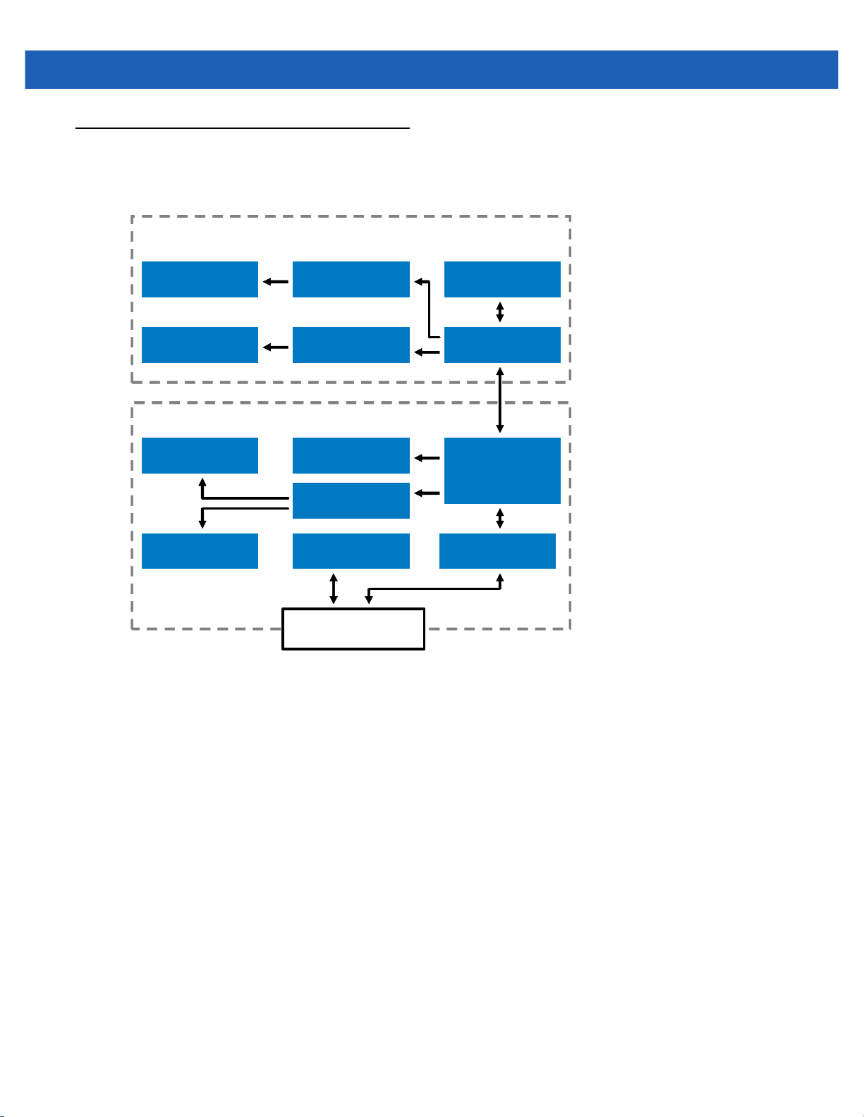
Block Diagram
LED Illumination
Driver
SE4500 Engine
Illumination LEDs
Laser Aimer Laser Aimer Driver Microprocessor
WVGA Sensor
Internal Beeper Internal Trigger
Interface CircuitryGreen/Red LEDs
Atmel AT91SAM9G20
MIcroprocessor,
RAM, and Flash
Power Regulation
Decoder/Interface
DB-9 Connector
User Interface
Drivers
The DS457 imager block diagram illustrates the functional relationship of the DS457 components. This section
also provides a description of each component in the block diagrams.
Getting Started 1 - 3
Figure 1-2
DS457 Block Diagram

1 - 4 DS457-XX20004ZZWW Fixed Mount Imager Integration Guide
DS457 Block Diagram Descriptions
SE4500 Imaging Engine - The SE4500 imaging engine captures 8-bit gray scale WVGA images at up to 60
fps, which are sent uncompressed to a companion board for processing. The engine uses a red laser for intuitive
aiming and features LED illumination. The engine is available in two focusing configurations, providing a choice
between high resolution and longer depth of field.
DS457 Decoder/Interface Board - The decoder/interface board is a companion decoder module for the
SE4500 imaging engine, which controls the engine, receives images, decodes 1D and 2D symbologies, and
performs various image processing tasks. The board controls a beeper and red and green LEDs for acoustic
and visual feedback, respectively. It also provides imaging for an external trigger and external beeper via the
DB9 connector. The board supports asynchronous serial (the standard Symbol Simple Serial Interface/SSI
command set) and SNAPI (Symbol Native API) interfaces, as well as a variety of other USB and RS-232 host
interfaces.
DB9 - The DB9 connector provides an outlet for the various interface signals used between the DS457 and the
host. It also provides power to the unit.
DS457 Decoder/Interface Board
Atmel AT91SAM9G20 Processor
The digital system is built on an Atmel AT91SAM9G20, a RISC processor based on ARM v5TEJ architecture.
The major features of the core are:
•
CPU clock speed up to 400 MHz with external LP SDRAM bus speed of 133 MHz
•
32 KB instruction/32 KB data cache, 256 KB instruction cache, 32 KB internal SRAM
Power Management
The DS457 decoder/interface board has various power management options depending on the host interface.
•
USB (SNAPI, USB HID Keyboard, etc.) - The DS457 automatically manages its power usage, including
USB suspend mode. Additionally, when drawing power from the USB bus, the DS457 does not exceed
the USB limit of 500 mA.
•
SSI or RS-232 - When using SSI or any RS-232 host interface, the DS457 uses one of the following power
modes. See Power Mode (RS-232 Hosts Only) on page 6-15.
• Continuous Power: The DS457 is fully awake and running, even when not in a decode session.
• Low Power (default): The DS457 draws less current at idle than when in Continuous Power mode.

CHAPTER 2INSTALLATION
Overview
This chapter provides information on unpacking, mounting, and installing the imager.
Unpacking
Remove the DS457 from its packing and inspect for damage. If the imager is damaged, call Zebra Global
Customer Support on page xix.
KEEP THE PACKING. It is the approved shipping container and should be used if the equipment needs to be
returned for servicing.
Mounting
There are two M3 x .5 tapped holes on the bottom of the DS457 housing for mounting. The following figures
provide the mounting dimensions.
NOTE
Do not use screws that penetrate more than 3.5 mm into the bottom mousing of the DS457 since this is the
maximum depth of the useful thread.

2 - 2 DS457-XX20004ZZWW Fixed Mount Imager Integration Guide
DS457 Mounting Dimensions
Note: Dimensions are in mm.
Figure 2-1
DS457 Mounting Dimensions

Installation 2 - 3
Mounting the Imager on the Gooseneck Stand
To mount the imager on the optional gooseneck stand:
1. Mount the DS457 to the mount plate. Align the imager so its window faces the short edge of the plate, and
its two threaded inserts align with the stand’s two mounting holes that are closest to the edge of the plastic.
Note that the imager requires only two screws for mounting.
2. Secure the imager to the stand using the two screws provided with the stand.
Assembling the Stand
1. Unscrew the wingnut
Imager mount
Mounting holes
Flat areas
from the bottom of the
one-piece mount.
2. Fit the bottom of the
neck piece into the
opening on the top of the
stand base.
3. Tighten the wingnut
underneath the base to
secure the cup and neck
piece (see the note
below).
4. Bend the neck to the
desired position for
scanning.
Stand base
Wingnut
Figure 2-2
Assembling the Gooseneck Stand
NOTE
Before tightening the wingnut under the base, ensure that the flat areas on the flexible neck fit securely in
the grooves in the base.
Mounting the Stand (optional)
You can attach the base of the stand to a flat surface using two screws or double-sided tape (not provided).
Screw Mount
1. Position the assembled base on a flat surface.
2. Screw one #10 wood screw into each screw-mount hole until the base of the stand is secure.

2 - 4 DS457-XX20004ZZWW Fixed Mount Imager Integration Guide
Tape Mount
1. Peel the paper liner off one side of each piece of tape and place the sticky surface over each of the three
rectangular tape areas.
2. Peel the paper liner off the exposed sides of each piece of tape and press the stand on a flat surface until
it is secure.
Two screw-mount holes
Double-sided tape
areas (3 places)
(dimensions = 1” x 2”)
Figure 2-3
Mounting the Stand

Mounting the Imager on the POS Stand
To mount the imager on the optional POS stand:
1. Mount the imager to the bracket assembly using the two mounting screws provided.
Installation 2 - 5
Figure 2-4
2. Secure the microphone-style clip to the mounting surface using the two screws provided.
Figure 2-5
Mounting Imager on Bracket Assembly
Securing Microphone Clip

2 - 6 DS457-XX20004ZZWW Fixed Mount Imager Integration Guide
3. Slide the bracket assembly with the imager attached onto the microphone-style clip.
Figure 2-6
Assembling the POS Stand
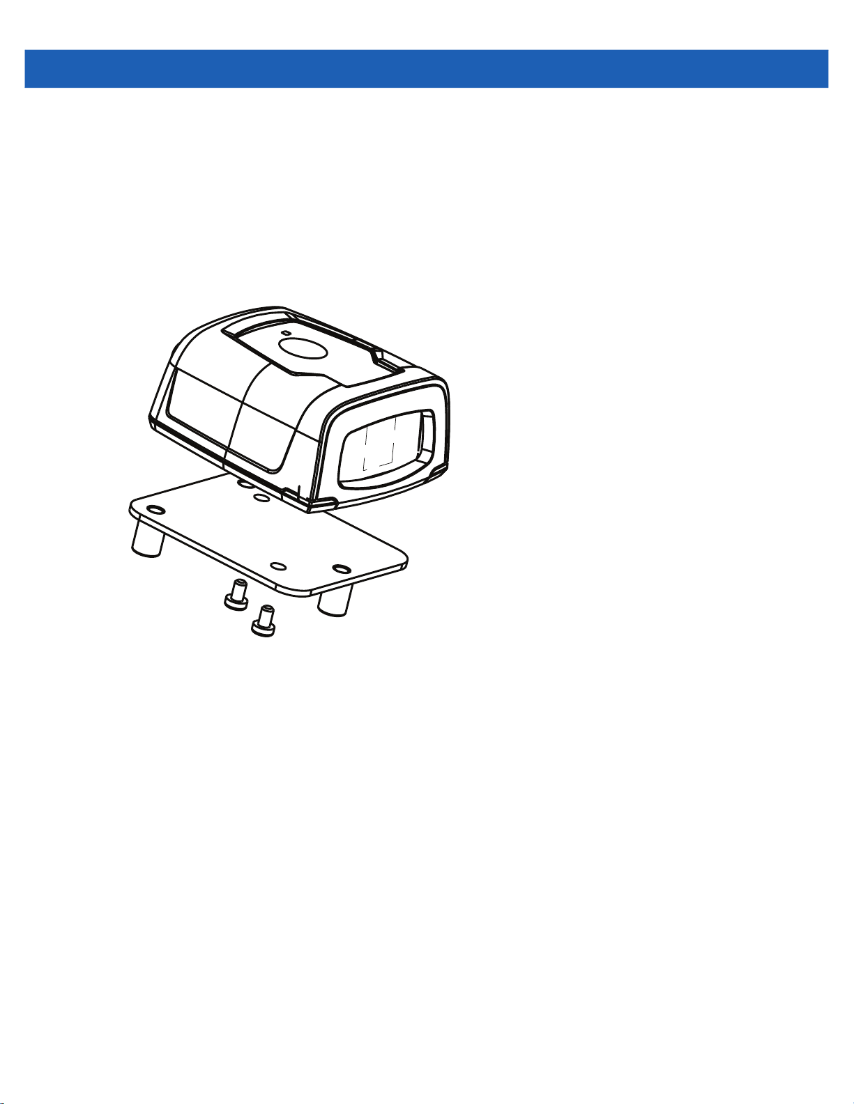
Installation 2 - 7
Mounting the Imager on the MS320X Conversion Mounting Bracket
To mount the imager on an existing MS320X mounting bracket:
1. Remove the MS320X from its original mounting.
2. Mount the DS457 imager to the conversion mounting bracket using the two mounting screws provided.
3. Place the conversion bracket on top of the existing MS320X bracket, aligning the standoffs with the
existing mounting screws.
Figure 2-7
Replacing a Mounted MS320X with the DS457

2 - 8 DS457-XX20004ZZWW Fixed Mount Imager Integration Guide
Connecting the DS457

Installation 2 - 9
USB Host Connection
1. Plug the 9-pin D-connector with the end marked SCANNER into the DS457.
2. If using an external switch and applicable host cable, plug the trigger cable into the female stereo
connector on the flying lead of the 9-pin D-connector. See Figure 2-10 on page 2-12 for connector
pins.
3. Plug the host connector into the appropriate port on the host.
4. Check all connections to ensure they are secure.
5. Program the DS457 using the programming bar codes in this guide.
Host Connector
9-pin D-connector
Figure 2-8
Trigger or Photo
Sensor (Optional)
Trigger Jack (Optional)
See Figure 2-10
USB Connection
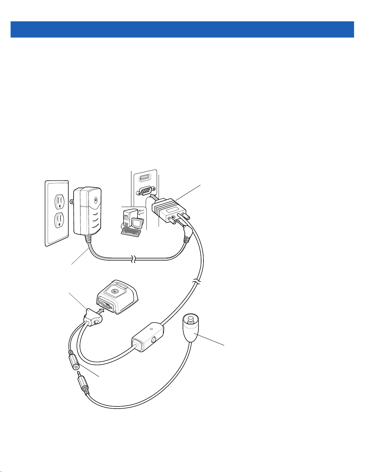
2 - 10 DS457-XX20004ZZWW Fixed Mount Imager Integration Guide
Serial Host Connection
1. Plug the 9-pin D-connector with the end marked SCANNER into the DS457. See Serial Interface Cable
Connection on page 2-11 to determine which cable to use.
2. If using an external switch and applicable host cable, plug the trigger cable into the female stereo
connector on the flying lead of the 9-pin D-connector. See Figure 2-10 on page 2-12 for connector
pins.
3. Plug the host connector into the appropriate port on the host.
4. Plug the power supply into an AC receptacle, and the output cable from the power supply into the
connector near the host end of the interface cable.
5. Check all connections to ensure they are secure.
6. Program the DS457 using the programming bar codes in this guide.
Host Connector
Power Supply
9-pin D-connector
Figure 2-9
Trigger or Photo
Sensor (Optional)
Trigger Jack (Optional)
See Figure 2-10
Serial Connection

Installation 2 - 11
Serial Interface Cable Connection
When connecting via RS-232, identify the type of host system to determine the cable needed. If you are unsure
what host system you are using, contact the local Zebra representative.
TTL Level Compatible RS-232 Host Systems
If using a PC, laptop, or POS terminal, the host system most likely has an RS-232 port which is compatible with
TTL levels. In this case, use the standard 5V RS-232 cable.
Host Systems Which Require True RS-232 Levels
Some host devices are not compatible with TTL level signals and require true RS-232 levels, such as those in
electrically noisy environments and locations with long cable runs. In such installations the DS457 may require
a level-shifting cable, such as p/n 25-62186-03R, to interface to this host system.
Failure to use the appropriate cable can impact the imager’s ability to reliably communicate with the host under
some conditions.

2 - 12 DS457-XX20004ZZWW Fixed Mount Imager Integration Guide
Male jack shown for reference
Note: Due to many variations of
jack and socket styles, identify
terminals as shown before
soldering leads.
1
1
2
2
3
3
Insertion
Direction
1 - Ground (Sleeve)
2 - Battery (Middle Contact)
3 - Trigger (Tip)
Trigger Jack Connector Pins
1 - Ground (Sleeve)
2 - Vcc (Middle Contact)
3 - Trigger (Tip)
Figure 2-10
Trigger Jack Connector Pins
Location and Positioning
The location and positioning guidelines do not consider unique application characteristics. Zebra recommends
that an opto-mechanical engineer perform an opto-mechanical analysis prior to integration.
NOTE
Integrate the imager in an environment no more extreme than the product’s specification, where the
imager will not exceed its temperature range. For instance, do not mount the imager onto or next to a large
heat source. When placing the imager with another device, ensure there is proper convection or venting
for heat. Follow these suggestions to ensure product longevity, warranty, and overall satisfaction with the
imager.

Embedded Applications Requiring a Window
!
Use the following guidelines for applications that require a window in front of the DS457.
NOTE
Zebra does not recommend placing an exit window in front of the DS457; however, the following
information is provided for applications that require such a window.
Window Material
NOTE
Consider the following window placement and material recommendations if mounting the DS457 within a
product with its own window.
Many window materials that look perfectly clear can contain stresses and distortions that can reduce imager
performance. For this reason, Zebra highly recommends optical glass or cell-cast acrylic. Following is a
description of acrylic and CR-39, another popular window material. Table 2-1 outlines the suggested
window properties.
Installation 2 - 13
CAUTION
NOTE
Consult an opto-mechanical engineer to recommend an appropriate window material and to
determine if coatings are appropriate for the specific application.
Do not use polycarbonate material.
Acrylic (PMMA)
When fabricated by cell-casting, acrylic has very good optical quality and low initial cost. However, protect the
surface from the environment as acrylic is susceptible to attack by chemicals, mechanical stresses, and UV light.
Acrylic has reasonably good impact resistance and can be ultrasonically welded.
CR-39 (ADC)
CR-39 is a thermal-setting plastic produced by the cell-casting process, and is commonly used in plastic eye
glasses lenses. CR-39 has excellent chemical and environmental resistance, including good surface hardness.
Typically it does not require hard-coating, but can be hard coated for severe environments. CR-39 has
reasonably good impact resistance and cannot be ultrasonically welded.
Chemically Tempered Float Glass
Glass is a hard material which provides excellent scratch and abrasion resistance. However, unannealed glass
is brittle. Increasing flexibility strength with minimal optical distortion requires chemical tempering. Glass cannot
be ultrasonically welded and is difficult to cut into odd shapes.

2 - 14 DS457-XX20004ZZWW Fixed Mount Imager Integration Guide
Table 2-1
Material Clear cell-cast acrylic.
Spectral Transmission 85% minimum at 400 - 700 nm.
Thickness 0.059 ± 0.005
Wavefront Distortion (transmission) 0.2 wavelengths peak-to-valley maximum over any 0.08 in.
Clear Aperture To extend to within 0.04 in. of the edges all around.
Surface Quality 60-20 scratch/dig
Suggested Window Properties
Property Description
diameter within the clear aperture.

Installation 2 - 15
Window Coatings
Table 2-3 lists some exit window manufacturers and anti-reflection coaters.
Anti-Reflection Coatings
Anti-reflection coatings can be used to achieve maximum working range and to improve the range of acceptable
window positions. However, they are expensive. AR coatings also have very poor abrasion and scratch
resistance, making only single-side AR coating practical (the AR coated side of the window faces the interior of
the imager).
Polysiloxane Coating
Apply polysiloxane type coatings to plastic surfaces to improve the surface resistance to both scratch and
abrasion. Typically, you apply these by dipping, then air-drying in an oven with filtered hot air.
Table 2-2
Chemically Tempered Float Glass 1.20% 1.50% Best
PMMA with Polysiloxane Hardcoat 3% 10%
ADC 5% 30%
PMMA 30% Worst
* All measurements use a 100 gram load and CS-10F abraser.
Table 2-3
Evaporated Coatings, Inc.
2365 Maryland Road
Willow Grove, PA 19090
(215) 659-3080
Fosta-Tek Optics, Inc.
320 Hamilton Street
Leominster, MA 01453
(978) 534-6511
Taber Test Results on Common Exit Window Materials
Sample
Window Manufacturers and Coaters
Company Discipline Specifics
Anti-reflection coater Acrylic window supplier
Cell-caster, hard coater, laser
cutter
Haze 100
cycles
Haze 500
cycles
Anti-reflection coater
CR39 exit window
manufacturer
Abrasion
Resistance

2 - 16 DS457-XX20004ZZWW Fixed Mount Imager Integration Guide
Table 2-3
Optical Polymers Int. (OPI)
110 West Main Street
Milford, CT 06460
(203) 882-9093
Polycast
70 Carlisle Place
Stamford, CT 06902
(800) 243-9002
TSP
2009 Glen Parkway
Batavia, OH 45103
(800) 277-9778
Window Manufacturers and Coaters (Continued)
Company Discipline Specifics
CR-39 cell-caster, coater,
laser cutter
Acrylic cell-caster, hard coater,
laser cutter
Acrylic cell-caster, coater,
laser cutter
CR39 exit window
manufacturer
Acrylic exit window
manufacturer
Acrylic exit window
manufacturer

Embedded Window Angle and Position
If you are placing a window between the DS457 and the target, observe the following guidelines:
•
Window Clear Opening - Make the clear opening of the window large enough so that the entire imager
clear aperture passes through the window. Cutting off any part of the clear aperture can degrade decode
range performance. Ensure that window placement relative to the DS457 accounts for tolerances on all
parts involved in that assembly.
•
Window Angle - Minimum window tilt is indicated in Table 2-4 on page 2-19. Further tilting the window is
acceptable and decreases the possibility of a secondary reflection from that window degrading the
imager's performance.
•
Minimum Window Distance - 5 mm.
•
Optical Working Range - Adding a window can reduce the working range of the imager since there is a
signal loss when passing through window material. To minimize this reduction, use a special coating
described in Window Coatings on page 2-15. To understand the difference, test the imager in the desired
orientation and see if the difference affects imager performance.
Installation 2 - 17

2 - 18 DS457-XX20004ZZWW Fixed Mount Imager Integration Guide
Notes:
1. Imaging axis pointing tolerance vs. datums ABC:
± 4º horizontal; ± 3º vertical
2. Clipping the imager clear aperture is not permitted.
3. Dimensions are in mm.
4. User mounting tolerances are not included.
Figure 2-11
DS457 Optical Path and Exit Window

Recommended Exit Window Information
Note: Minimum external window distance
b = 5 mm (see Table 2-4).
Installation 2 - 19
Figure 2-12
Table 2-4
Window Distances
Recommended Exit Window Information - Tilted Window
External Window Specification Minimum Window Angle
Non-coated, minimum window positive tilt (+c)
Non-coated, minimum window negative tilt (-c)
AR coated, one side, minimum window positive tilt (+c)
AR coated, one side, minimum window negative tilt (-c)
AR coated, two sides, minimum window positive tilt (+c)
AR coated, two sides, minimum window negative tilt (-c)
31
31
26
27
23
17
o
o
o
o
o
o

2 - 20 DS457-XX20004ZZWW Fixed Mount Imager Integration Guide
Exit Window Notes
•
Integration tolerances are not included.
•
Ensure the window size is large enough to cover the engine clear aperture specified in Figure 2-11 plus
mounting tolerances of the window relative to the engine.
Accessories
Zebra offers the following accessories for the imager. Refer to Solution Builder (ordering guide).
Table 2-5
Power Supplies (RS-232)*
5 VDC 850 mA; US, Canada, Mexico, Japan, Taiwan PWRS-WUA5V4W0US
5 VDC 850 mA; EU, UK, EMEA, Russia, South Africa PWRS-WUA5V4W0EU
5 VDC 850 mA; China PWRS-WUA5V4W0CN
5 VDC 850 mA; Australia, Hong Kong, New Zealand PWRS-WUA5V4W0AU
RS-232
9-Pin female (DB9) with straight connector, 6 ft, with trigger jack, no beeper 25-13227-03R
9-Pin female (DB9) with straight connector, 6 ft, with trigger jack and beeper 25-13228-03R
9-Pin female (DB9) with straight connector, 6 ft, no trigger jack or beeper CBL-58918-02
9-Pin female (DB9) coiled, 9 ft, no trigger jack or beeper CBL-58918-03
TTL RS-232 to true RS-232 conversion cable, low profile connector 25-62186-03R
USB
9-Pin female (DB9) with straight connector, 6 ft, with trigger jack and beeper 25-58925-02R
DS457 Imager Accessories
Accessory Part Number
9-Pin female (DB9) with straight connector, 6 ft, no trigger jack or beeper CBL-58926-04
9-Pin female (DB9), 18 in, no trigger jack or beeper (for kiosks) CBL-58926-05
9-Pin female (DB9), coiled, 9 ft, no trigger jack or beeper CBL-58926-06
Optional Accessories
Push button trigger cable 25-04950-01R
Gooseneck stand (twilight black) 20-60136-02R
Adjustable mounting bracket, requires adapter plate (see next line item) KT-65578-01R
Adapter plate for adjustable mounting bracket KT-152342-01
POS wall/counter mount
MS320x to DS457 conversion mounting bracket
*Standalone power supply is not used for USB hosts.
KT-145344-01
KT-152342-01

Installation 2 - 21
Simple Serial Interface Software Developer's Kit (SSI SDK)
The SSI Software Developer's Kit, available on Zebra’s website, provides the software tools used to integrate
and communicate with the DS457 imagers via RS-232, including:
•
Sample Windows® program with source code
•
DLL with source code for building user applications
•
ActiveX component (including help file) for easy integration into VisualBasic programs
•
Simple Serial Interface documentation.
With over 70 programmable parameters, you can configure DS457 imagers using bar code menus, or through
the serial interface using Zebra’s Simple Serial Interface protocol.
For Windows
imager’s features and obtain maximum performance.
To download the SDK, go to: http://www.zebra.com/support.
®
, DOS, and embedded system environments, this enables you to take full advantage of the
Zebra SNAPI Software Developer's Kit
The Symbol Native Application Programming Interface Software Development Kit (SNAPI SDK) facilitates
communicate with SNAPI-based Zebra scanners over USB, providing the following features:
•
Bar code capture and decode
•
Image and video capture
•
Electronic scanner configuration and software update
•
Reference sample application in Microsoft Visual C#® .NET.
To download the SDK, go to: http://www.zebra.com/support.

2 - 22 DS457-XX20004ZZWW Fixed Mount Imager Integration Guide

CHAPTER 3IMAGING
Overview
This chapter provides information on aiming, illumination, data capture, beeper and decode LED feedback,
supported symbologies, and operating modes.
Imaging System
Aiming Pattern
A 655 nm laser and a pattern forming element generate a laser aiming pattern which represents the imager's
field of view throughout its entire depth of field. The pattern's center dot indicates the center of the field of view.
Figure 3-1
The bright center spot provides visibility for aiming in sunlight and other bright light applications. The aiming
pattern indicates the field of view for capturing images. The ends of the horizontal and vertical lines represent
the midpoints of the sides of an imaginary box outlining the capture field.
Aiming Pattern
Aiming Error
The aiming pattern is rotated by 2o relative to the imaging axis in the horizontal plane to minimize parallax
between the aiming axis and the imaging axis at 190 mm (7.5 in.) from the imager.

3 - 2 DS457-XX20004ZZWW Fixed Mount Imager Integration Guide
Aiming Control
The DS457 can capture images with both the aiming subsystem turned on during exposure (the image of the
aiming pattern is visible in the digital image) or off. If the aiming system is turned off during exposure,
brightness of the aiming pattern decreases as exposure increases.
Illumination System
The illumination system consists of two high-output, red LEDs (625 nm) and a sophisticated drive system that
allows image capture and decoding throughout a full range of lighting conditions (total darkness to full
sunlight).
Illumination Control
The DS457 can capture images with the illumination subsystem turned on or off, accommodating images that
are close to the wavelength of the illumination. For example, since the imager uses red LED illumination, it may
be desirable to shut off the illumination when capturing an image printed in red ink.
It is recommended to turn off LED illumination and provide minimum 30 fcd ambient light on the document
surface when taking images of documents. Even a small amount of dust or fingerprints on the imager window
can scatter the LED illumination and create glare in the image. The glare reduces quality of document images
but does not affect bar code reading.
Frame Rate Control
The DS457 outputs images at 60 frames per second by default. When capturing images, use lower frame rates
to increase image brightness. The aiming pattern and illumination appear to blink when the frame rate is 30 fps
or lower.
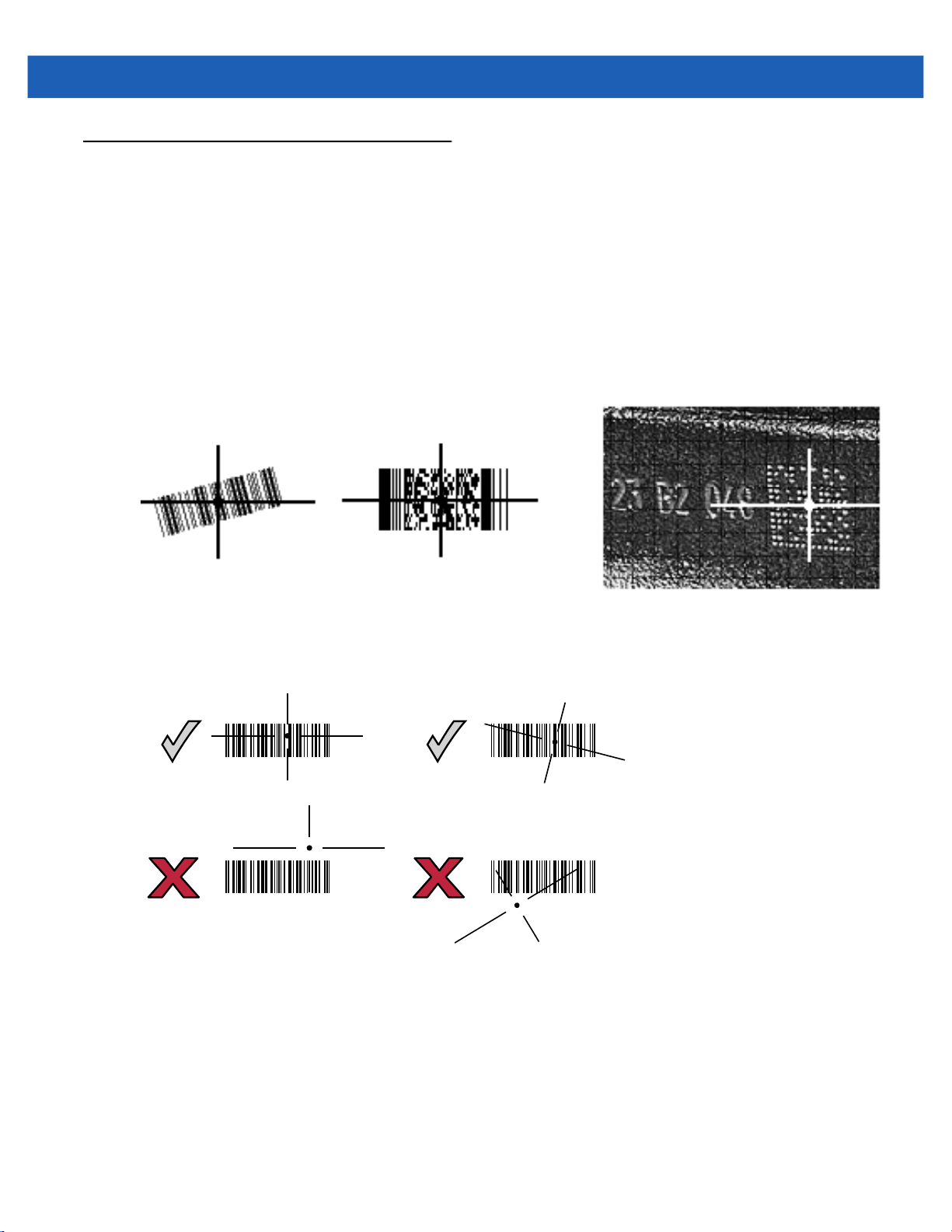
Capturing Data
012345
012345
012345
012345
When scanning, the imager projects a red laser aiming pattern which allows positioning the bar code within its
field of view. See Decode Zones on page 4-6 for the proper distance to achieve between the imager and a bar
code. The imager turns on its red LEDs to illuminate the target bar code.
In Presentation Mode (default), when the DS457 detects an object in its field of view, it automatically triggers
and displays the aiming pattern. In triggered mode, press the trigger button on top of the imager to display the
aiming pattern.
To scan a bar code, center the symbol in any orientation within the aiming pattern. Be sure the entire symbol is
within the rectangular area formed by the cross pattern.
1D bar code symbol
2D bar code symbol
Imaging 3 - 3
2D dot peen symbol
Figure 3-2
Scanning Orientation with Imager Aiming Pattern
The imager can also read a bar code presented within the aiming pattern but not centered. The top examples
in Figure 3-3 show acceptable aiming options, while the bottom examples can not be decoded.
Figure 3-3
Acceptable and Incorrect Aiming
Upon successful decode, the DS457 beeps and its feedback LED turns green.

3 - 4 DS457-XX20004ZZWW Fixed Mount Imager Integration Guide
Beeper and Decode LED Indications
Table 3-1 provides beeper and LED indications related to certain events. The LED illuminates red to indicate
that the imager has power. SSI events are also listed.
Table 3-1
Trigger pull No sound Red TRIGGER_PULLED
No decode NODECODE_MSG
Wakeup WAKEUP
Video is off VIDEO_OFF
Video is on VIDEO_ON
Decode Middle Tone Flash of green DECODE
Snapshot started Low Tone Blinking green SNAPSHOT_START
Snapshot is complete Low Tone Red SNAPSHOT_COMPLETE
Bootup Low Tone, Middle
Transmission error Four Low Tones Red TRANSMIT_ERROR
Entry error Low Tone, High Tone Flash of green ENTRY_ERROR
User Interface Indications
Description
Beeper
Tone, High Tone
Indication
Red BOOTUP
Power/Decode
LED
SSI Event
Defaults set High Tone, Low Tone,
High Tone, Low Tone
Parameter entered PARAM_ENTERED
Number entry expected High Tone, Low Tone Flash of green NUMBER_EXPECTED
Flash of green DEFAULTS_SET

Supported Symbologies
The following bar code types are supported and can be individually enabled or disabled:
1D Symbologies 2D Symbologies
UPC/EAN PDF417
Bookland EAN MicroPDF417
UCC Coupon Code Data Matrix, Data Matrix Inverse
ISSN EAN GS1 Data Matrix
Code 128 Maxicode
GS1-128 QR Code
ISBT 128 GS1 QR
Code 39 MicroQR
Trioptic Code 39 Aztec, Aztec Inverse
Code 32 Han Xin, Han Xin Inverse
Code 93 Grid Matrix, Grid Matrix Inverse, Grid Matrix Mirrored
Code 11
Interleaved 2 of 5 Postal Codes
Discrete 2 of 5 US Postnet
Codabar US Planet
MSI UK Postal
Chinese 2 of 5 Japan Postal
Matrix 2 of 5 Australia Post
Korean 3 of 5 Netherlands KIX Code
Inverse 1D USPS 4CB/One Code/Intelligent Mail
GS1 DataBar UPU FICS Postal
Composite Codes
Imaging 3 - 5
Mailmark
Operating Modes
The DS457 supports the following operating modes. See Operational Modes on page 7-4 for information on
changing between modes.
•
Decode (default mode) - for decoding a bar code
•
Snapshot - for capturing an image
•
Snapshot with Viewfinder Mode - provides a video of the subject until a snapshot of the image is
captured.
•
Video - provides a video of the subject

3 - 6 DS457-XX20004ZZWW Fixed Mount Imager Integration Guide

CHAPTER 4SPECIFICATIONS
Electrical Interface
Figure 4-1
Table 4-1 lists the pin functions of the DS457 interface.
Table 4-1
Pin No. Pin Name Pin No. Pin Name
1 Trigger 1 Trigger
2 NC 2 TXD Output TTL Only
3 USB + 3 RXD Input TTL Only
4 Connect to Pin 8 4 NC
5 Ground 5 Ground
6 +5V Power 6 +5V Power
7 USB - 7 CTS Input TTL Only
8 Connect to Pin 4 8 RTS Output TTL Only
9 Beeper/Download 9 Beeper/Download
NC = No Connect (do not connect this pin)
DS457 Connector
DS457 USB and Serial Electrical Interface
USB Interface Serial Interface
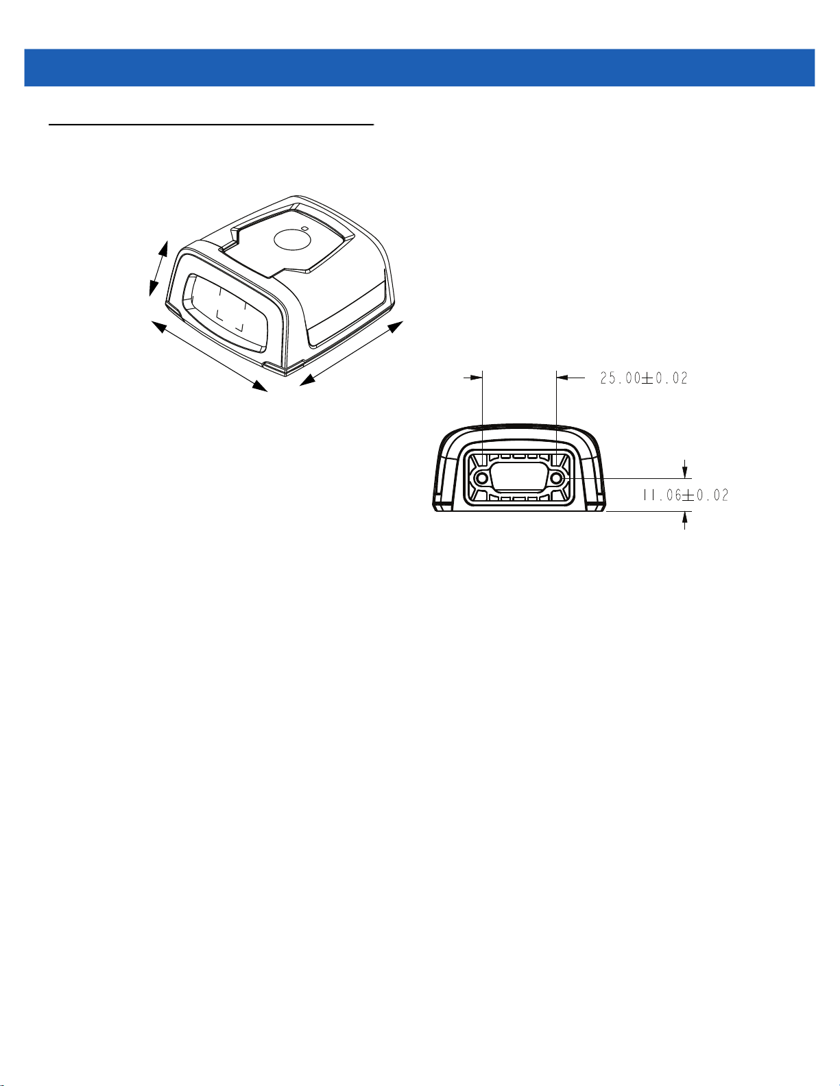
4 - 2 DS457-XX20004ZZWW Fixed Mount Imager Integration Guide
Dimension Drawings
29.2 mm
58.4 mm
Figure 4-2
62.0 mm
Back View
DS457 Dimension Drawings

DS457 Imager Technical Specifications
Specifications 4 - 3
Table 4-2
Performance Characteristics
Sensor Resolution 752 x 480 pixels
Field of View DS457-SR/DL: 39.6º horizontal, 25.7º vertical
Pitch/Skew/Roll Tolerance ± 60º / ± 60º / 360º (see Figure 4-3 on page 4-5)
Focal Distance from Front of Imager
Housing
Aiming Element (VLD) 655 nm ± 10 nm
Illumination Element 625 nm ± 5 nm (LED)
Minimum Print Contrast 25% absolute dark/light reflectance
User Environment
Power Requirements
Supply Voltage
Low Power / Suspend Current
Draw
Idle Current
Operating Current
(scan/decode session)
Peak Current
DS457 Technical Specifications at 23° C
Item Description
DS457-HD/DP: 38.4º horizontal, 24.9º vertical
DS457-SR/DL: 4.7 in.
DS457-HD/DP: 2.3 in.
5.00 V ± 0.5 V
2.5 mA (typical)
160 mA (typical)
280 mA (average)
450 mA
Ambient Light Immunity Total darkness to 9,000 ft. candles (96,900 lux)
Humidity
Operating
Storage
Drop Rating Unit functions normally after multiple 30 in (76 cm) drops to tile over
Temperature
Operating
Storage
Note: Environmental and/or tolerance parameters are not cumulative. Perform a thermal analysis if
the application is subject to an extreme temperature environment.
95% RH, non-condensing at 50º C
85% RH, non-condensing at 70º C
concrete
-4º to 122º F (-20º to 50º C)*
-40º to 158º F (-40º to 70º C)
* Above 45ºC the laser aimer is disabled. In high temperature
environments the DS457 safeguards the laser from overheating by
monitoring the internal system temperature. For this reason, if Time
Delay to Presentation Idle Mode is set to a high value and the aiming
pattern remains on for an extended period of time while in
presentation mode, the imager may temporarily shut off the aiming
pattern.

4 - 4 DS457-XX20004ZZWW Fixed Mount Imager Integration Guide
Table 4-2
Dimensions 1.15 in. (29.2 mm) H x 2.30 in. (58.4 mm) W x 2.44 in. (62.0 mm) D
Weight 3.9 oz. (111.0 grams)
Interface 9-pin male D-sub supports USB (full speed) and TTL level RS-232
Note: Environmental and/or tolerance parameters are not cumulative. Perform a thermal analysis if
the application is subject to an extreme temperature environment.
DS457 Technical Specifications at 23° C (Continued)
Item Description
with RTS and CTS
Skew, Pitch and Roll
Measured on a 20 mil Code 39 symbol at a distance of 10 inches. Tolerance is reduced at extreme ends of the
working range.

Specifications 4 - 5
Skew Pitch
+ 50° from normal
+
60° from normal
Roll
360°
Note: Tolerances are
reduced at extreme ends
of the working range.
Figure 4-3
Skew, Pitch and Roll

4 - 6 DS457-XX20004ZZWW Fixed Mount Imager Integration Guide
Decode Zones
DS457-SR/DL
Figure 4-4 shows the decode zone for the DS457-SR/DL. Typical values appear. Table 4-3 lists the typical and
guaranteed distances for selected bar code densities. The minimum element width (or “symbol density”) is the
width in mils of the narrowest element (bar or space) in the symbol.
Note: Typical performance at 73˚F (23˚C)
on high quality symbols.
DS457-SR/DL
7.5 mil Data Matrix
2.0
5 mil Code 39
1.3
10 mil Data Matrix
1.5
1.6
1.5
15 mil Data Matrix
6.0
8.1
8.4
13 mil (100% UPC)
10.9
15.3
in.
20
10
0
10
20
cm
50.8
25.4
0
25.4
50.8
W
i
d
t
h
o
f
F
i
e
l
d
In.
cm
Figure 4-4
1.8
0
0
4
10.2 20.3
20 mil Code 39
8
12 16
30.5
40.6
16.5
20
50.8
Depth of Field
DS457-SR/DL Decode Zone - 1D and Data Matrix Symbols

Specifications 4 - 7
Note: Typical performance at 73˚F (23˚C)
on high quality symbols.
DS457-SR/DL
7.5 mil QR Code
2.1
5 mil PDF417
2.4
10 mil QR Code
1.5
6.67 mil PDF417
1.8
1.2
5.1
6.2
10 mil PDF417
7.0
7.1
10.2
in.
20
10
10
20
cm
50.8
W
i
d
25.4
t
h
0
0
o
f
F
25.4
i
e
l
d
50.8
In.
cm
Figure 4-5
1.5
0
0
15 mil PDF417
4
8
10.2 20.3
13.0
12 16
30.5
40.6
Depth of Field
DS457-SR/DL Decode Zone - QR Code and PDF417 Symbols

4 - 8 DS457-XX20004ZZWW Fixed Mount Imager Integration Guide
Table 4-3
Symbol Density/
Bar Code Type
5.0 mil
Code 39
20 mil
Code 39
13 mil
100% UPC
7.5 mil
Data Matrix
10 mil
Data Matrix
15 mil
Data Matrix
7.5 mil
QR Code
DS457-SR/DL Decode Distances (Presentation Mode)
Typical Working Ranges
Near Far Near Far
1.3 in
3.30 cm
1.8 in
4.57 cm
1.5 in
3.81 cm
2.0 in
5.08 cm
1.5 in
3.81 cm
1.6 in
4.06 cm
2.1 in
5.33 cm
8.1 in
20.57 cm
16.5 in
41.91 cm
15.3 in
38.86 cm
6.0 in
15.24 cm
8.4 in
21.34 cm
10.9 in
27.69 cm
5.1 in
12.95 cm
Guaranteed Working
Ranges
1.6 in
4.06 cm
Note 1 11.6 in
2.1 in
5.33 cm
N/A N/A
N/A N/A
N/A N/A
N/A N/A
6.3 in
16.00 cm
29.46 cm
9.5 in
24.13 cm
10 mil
QR Code
5.0 mil
PDF417
6.67 mil
PDF417
10 mil
PDF417
15 mil
PDF417
Notes:
1. Near distances are field-of-view (FOV) limited.
2. Contrast is measured as Mean Reflective Difference (MRD) at 670 nm.
3. Working range specifications at temperature = 23°C, pitch=18°, roll=0°,
skew=0°, photographic quality, humidity 45-70% RH.
1.5 in
3.81 cm
2.4 in
6.10 cm
1.8 in
4.57 cm
1.2 in
3.05 cm
1.5 in
3.81 cm
7.0 in
17.78 cm
6.2 in
15.75 cm
7.1 in
18.03 cm
10.2 in
25.91 cm
13.0 in
33.02 cm
N/A N/A
3.1 in
7.87 cm
2.1 in
5.33 cm
Note 1 7.6 in
Note 1 10.1 in
3.5 in
8.89 cm
5.8 in
14.73 cm
19.30 cm
25.65 cm

Specifications 4 - 9
DS457-HD/DP
Figure 4-6 shows the decode zone for the DS457-HD/DP. Typical values appear. Table 4-4 lists the typical and
guaranteed distances for selected bar code densities. The minimum element width (or “symbol density”) is the
width in mils of the narrowest element (bar or space) in the symbol.
Note: Typical performance at 73˚F (23˚C)
on high quality symbols.
DS457-HD/DP
4 mil Data Matrix
1.6
3 mil Code 128
1.4
5 mil Data Matrix
1.4
7.5 mil Data Matrix
1.2
1.2
1.1
3.0
3.5
3 mil Code 39
5 mil Code 39
3.7
4.4
4.8
5.7
in.
10
10
cm
25.4
W
i
d
12.7
5
t
h
0
0
o
f
F
12.7
5
i
e
l
d
25.4
In.
cm
Figure 4-6
1.7
1.9
0
0
2
5.1 10.2
13 mil (100% UPC)
15 mil Code 128
20 mil Code 39
4
6
15.2
8
20.3
8.3
8.73.1
9.7
10
25.4
Depth of Field
DS457-HD/DP Decode Zone - 1D and Data Matrix Symbols

4 - 10 DS457-XX20004ZZWW Fixed Mount Imager Integration Guide
Note: Typical performance at 73˚F (23˚C)
on high quality symbols.
DS457-HD/DP
5 mil QR Code
1.5
1.4
7.5 mil QR Code
1.1
1.1
1.0
4 mil PDF417
10 mil QR Code
6.67 mil PDF417
3.1
3.8
4.0
4.6
4.8
in.
10
10
cm
25.4
W
i
d
12.7
5
t
h
0
0
o
f
F
12.7
5
i
e
l
d
25.4
In.
cm
Figure 4-7
1.4
0
0
20 mil QR Code
3.0
2
4
5.1 10.2
40 mil QR Code
6
15.2
6.8
8
20.3
10.4
10
25.4
Depth of Field
DS457-HD/DP Decode Zone - QR Code and PDF417 Symbols

Specifications 4 - 11
Table 4-4
Symbol Density/
Bar Code Type
3.0 mil
Code 39
5.0 mil
Code 39
20 mil
Code 39
3.0 mil
Code 128
15.0 mil
Code 128
13 mil
100% UPC
4 mil
Data Matrix
DS457-HD/DP Decode Distances (Presentation Mode)
Typical Working Ranges
Near Far Near Far
1.2 in
3.05 cm
1.1 in
2.79 cm
1.9 in
4.83 cm
1.4 in
3.56 cm
3.1 in
7.87 cm
1.7 in
4.32 cm
1.6 in
4.06 cm
4.8 in
12.19 cm
5.7 in
14.48 cm
9.7 in
24.64 cm
3.5 in
8.89 cm
8.7 in
22.10 cm
8.3 in
21.08 cm
3.0 in
7.62 cm
Guaranteed Working
Ranges
1.4 in
3.56 cm
Note 1 4.1 in
Note 1 9.3 in
N/A N/A
N/A N/A
2.1 in
5.33 cm
N/A N/A
3.0 in
7.62 cm
10.41 cm
23.62 cm
5.7 in
14.48 cm
5 mil
Data Matrix
7.5 mil
Data Matrix
5 mil
QR Code
7.5 mil
QR Code
10 mil
QR Code
20 mil
QR Code
Notes:
1. Near distances are FOV limited.
2. Contrast is measured as Mean Reflective Difference (MRD) at 670 nm.
3. Working range specifications at temperature = 23°C, pitch=18°, roll=0°,
skew=0°, photographic quality, humidity 45-70% RH.
1.4 in
3.56 cm
1.2 in
3.05 cm
1.5 in
3.81 cm
1.1 in
2.79 cm
1.1 in
2.79 cm
1.4 in
3.56 cm
3.7 in
9.40 cm
4.4 in
11.18 cm
3.1 in
7.87 cm
4.0 in
10.16 cm
4.6 in
11.68 cm
6.8 in
17.27 cm
N/A N/A
N/A N/A
N/A N/A
N/A N/A
N/A N/A
N/A N/A

4 - 12 DS457-XX20004ZZWW Fixed Mount Imager Integration Guide
Table 4-4
Symbol Density/
Bar Code Type
40 mil
QR Code
4.0 mil
PDF417
6.67 mil
PDF417
Notes:
1. Near distances are FOV limited.
2. Contrast is measured as Mean Reflective Difference (MRD) at 670 nm.
3. Working range specifications at temperature = 23°C, pitch=18°, roll=0°,
skew=0°, photographic quality, humidity 45-70% RH.
DS457-HD/DP Decode Distances (Presentation Mode) (Continued)
Typical Working Ranges
Near Far Near Far
3.0 in
7.62 cm
1.4 in
3.56 cm
1.0 in
2.54 cm
10.4 in
26.42 cm
3.8 in
9.65 cm
4.8 in
12.19 cm
Guaranteed Working
N/A N/A
1.6 in
4.06 cm
1.1 in
2.79 cm
Ranges
2.7 in
6.86 cm
3.6 in
9.14 cm

CHAPTER 5MAINTENANCE &
TROUBLESHOOTING
Overview
The chapter provides information on maintenance and troubleshooting.
Maintenance
Clean the imager housing and exit window with a damp cloth and, if necessary, a non-ammonia based
detergent. Do not allow any abrasive material to touch the exit window.
Cleaning the Connector
1. Remove the cable connector from the imager.
2. Rub a cotton-tipped applicator dipped in isopropyl alcohol back and forth across the connector pins. Do not
leave any cotton residue on the connector.
3. Rub a dry cotton-tipped applicator back and forth across the connector pins.
4. Spray compressed air on the connector area by pointing the tube/nozzle about ½ inch away from the
surface.
5. Inspect the area for any grease or dirt and repeat if required.
CAUTION
Do not get excess alcohol onto the soft elastomeric gasket since this can compromise the adhesion to
the housing and ultimately the gasket’s ability to prevent liquids from entering the imager in this area
during normal operation.

5 - 2 DS457-XX20004ZZWW Fixed Mount Imager Integration Guide
Troubleshooting
Table 5-1.
Problem Possible Cause Possible Solutions
No red LED or nothing
happens during a
capture attempt.
Imager cannot read the
bar code.
Aiming pattern does not
appear.
Laser activates, followed
by a beep sequence.
No power to the imager. Check the system power.
Confirm that the correct host interface cable is
used.
Connect the power supply.
Re-connect loose cables.
Interface/power cables are
loose.
Imager is not programmed for
the correct bar code type.
Incorrect communication
parameters.
Bar code symbol is
unreadable.
Hot environment. Remove the imager from the hot environment,
Beeper is configured. See Beeper and Decode LED Indications on
Re-connect loose cables.
Program the imager to read the type of bar code
to be decoded.
Set the correct communication parameters
(baud rate, parity, stop bits, etc.)
Ensure the symbol is not defaced.
Try capturing similar symbols of the same code
type.
and allow it to cool down.
page 3-4 for beeper indication descriptions.
NOTE
If after performing these checks the symbol still does not decode, contact the distributor or contact Zebra
Global Customer Support. See page xix for contact information.

CHAPTER 6USER PREFERENCES
Introduction
This chapter describes each user preference feature and provides the programming bar codes necessary for
selecting these features.
Host Selection
The default serial host is SSI and the default USB host is USB HID Keyboard, as these host types provide
more flexibility during integration when configuring the unit via host command. Selecting other host
configurations requires scanning bar code menus and cannot be performed via host programming. See each
host chapter for configuration options for each host type.
NOTE
The DS457 automatically switches between USB and serial host interfaces based on the type of cable
attached.
NOTE
Selecting one of the Serial Host Types on page 9-5 disables SSI support. To restore SSI support, scan
SSI Host on page 8-9.

6 - 2 DS457-XX20004ZZWW Fixed Mount Imager Integration Guide
Changing Default Values
The imager ships with the settings shown in the Table 6-1 on page 6-3 (also see Appendix A, Standard Default
Parameters for all host and miscellaneous defaults). If the default values suit requirements, programming is not
necessary.
There are two ways to change a parameter value:
•
Scan the appropriate bar codes in this guide. These new values replace the standard default values in
memory.
•
For SSI and USB SNAPI hosts, send a “parameter send” command from the host system. Hexadecimal
parameter numbers appear in this chapter below the parameter title, and options appear in parenthesis
beneath the accompanying bar codes. See the Simple Serial Interface (SSI) Programmer’s Guide for
detailed instructions for changing parameter values using this method.
NOTE
Most computer monitors allow scanning the bar codes directly on the screen. When scanning from the
screen, be sure to set the document magnification to a level where you can see the bar code clearly, and
bars and/or spaces are not merging.
To return all features to default values, scan *Restore Defaults on page 6-5. Throughout the programming bar
code menus, asterisks (
*) indicate default values.
* Indicates default
*High Volume
Scanning Sequence Examples
In most cases, scanning one bar code sets the parameter value. For example, to set the beeper tone to high,
scan the High Frequency (beeper tone) bar code listed under Beeper Tone on page 6-9. The imager issues a
fast warble beep signal and a good decode LED signal, signifying a successful parameter entry.
Other parameters, such as Decode Session Timeout, require scanning several bar codes. See these
parameter descriptions for this procedure.
Errors While Scanning
Unless otherwise specified, to correct an error during a scanning sequence, just re-scan the correct parameter.
Feature/Option
(0)
Option decimal value for
programming

User Preferences Parameter Defaults
Table 6-1 lists defaults for user preferences parameters. To change any parameter value, scan the appropriate
bar code(s) provided in the User Preferences section beginning on page 6-5.
NOTE
See Appendix A, Standard Default Parameters for all user preferences, hosts, symbologies, and
miscellaneous default parameters.
User Preferences 6 - 3
Table 6-1
User Preferences
Set Default Parameter Restore Defaults 6-5
Parameter Scanning 236 ECh Enable 6-6
Lock Parameter Scanning 802 F2h 22h Disable
Unlock Parameter Scanning 803 F2h 23h Disable
Beep After Good Decode 56 38h Enable 6-8
Beeper Tone 145 91h Medium 6-9
Beeper Volume 140 8Ch High 6-10
Suppress Power-up Beeps 721 F1h D1h Do not suppress 6-10
Trigger Mode 138 8Ah Presentation 6-11
Presentation Performance Mode 650 F1h 8Ah Standard 6-12
Time Delay to Presentation Sleep Mode 662 F1h 96h 1 Minute 6-13
Power Mode 128 80h Low Power 6-15
User Preferences Default Table
Parameter
Parameter
Number
SSI Number Default
Number
6-7
6-7
Page
Time Delay to Low Power Mode 146 92h 1.0 Sec 6-15
Picklist Mode 402 F0h 92h Disabled Always 6-17
Decode Session Timeout 136 88h 9.9 Sec 6-17
Timeout Between Decodes,
Same Symbol
Continuous Bar Code Read 649 F1h 89h Disable 6-18
Unique Bar Code Reporting 723 F1h D3h Enable 6-19
PDF Prioritization 719 F1h CFh Disable 6-20
PDF Prioritization Timeout 720 F1h D0h 400 ms 6-21
Product ID (PID) Type 1281 F8h 05h 01h Host Type Unique 6-21
DPM Mode (DS457-DP Only) 1438 F8h 05h 9Eh Enable DPM Mode 2 6-22
137 89h 0.6 Sec 6-18

6 - 4 DS457-XX20004ZZWW Fixed Mount Imager Integration Guide
Table 6-1
Miscellaneous Parameters
Add an Enter Key N/A N/A N/A 6-23
Transmit Code ID Character 45 2Dh None 6-23
SSI Prefix Value 105 69h <CR> 6-24
SSI Suffix 1 Value
SSI Suffix 2 Value
Non-SSI Prefix Value 99, 105 63h, 69h <CR><LF> 6-24
Non-SSI Suffix 1 Value
Non-SSI Suffix 2 Value
Scan Data Transmission Format 235 EBh Data as is 6-25
FN1 Substitution Values 103, 109 67h, 6Dh Set 6-26
Transmit “No Read” Message 94 5Eh Disable 6-27
Report Version 6-27
User Preferences Default Table
Parameter
Parameter
Number
104
106
98, 104
100, 106
SSI Number Default
68h
6Ah
62h, 68h
64h, 6Ah
<CR>
<CR>
<CR><LF>
<CR><LF>
Number
6-24
6-24
Page

User Preferences
Set Default Parameter
You can reset the DS457 to two types of defaults: factory defaults or custom defaults. Scan the appropriate bar
code below to reset the imager to its default settings and/or set its current settings as custom defaults.
•
Restore Defaults - Scan this bar code to reset all default parameters as follows.
• If you previously set custom defaults by scanning Write to Custom Defaults, scan Restore Defaults
to retrieve and restore the imager’s custom default settings.
• If you did not set custom defaults, scan Restore Defaults to restore the factory default values listed in
Table A-1.
•
Set Factory Defaults - Scan this bar code to restore the factory default values listed in Table A-1. This
deletes any custom defaults set.
•
Write to Custom Defaults - Scan this bar code to set the current imager settings as custom defaults.
Once set, you can recover custom default settings by scanning Restore Defaults.
User Preferences 6 - 5
*Restore Defaults
Write to Custom Defaults
Set Factory Defaults

6 - 6 DS457-XX20004ZZWW Fixed Mount Imager Integration Guide
Parameter Scanning
Parameter # 236 (SSI # ECh)
To disable the decoding of parameter bar codes, including the Set Defaults parameter bar codes, scan the
Disable Parameter Scanning bar code below. To enable decoding of parameter bar codes, scan Enable
Parameter Scanning.
*Enable Parameter Scanning
(1)
Disable Parameter Scanning
(0)

User Preferences 6 - 7
Lock/Unlock Parameter Scanning
Lock: Parameter # 802 (SSI # F2h 22h)
Unlock: Parameter # 803 (SSI # F2h 23h)
This feature locks parameter settings with a 4-digit code to prevent the user from changing parameter values
by scanning parameter bar codes. This provides an added level of security not offered via Disable Parameter
Scanning.
After locking parameter settings, the only the Unlock parameter bar code is accepted, with the correct code.
NOTE
Parameter Scanning must be enabled in order to scan the Lock parameter bar code. Once parameter
scanning is locked, scanning the Enable or Disable Parameter Scanning bar code results in a parameter
error beep.
1. To lock parameter scanning:
2. Scan the Lock bar code.
3. Scan four bar codes from Appendix G, Numeric Bar Codes that represent the desired code. Enter leading
zeros for numbers below 1000, e.g., to program a code of 29, enter 0, 0, 2, 9. A lock beep sounds (two
long high beeps) in addition to the parameter entry beep.
To unlock parameter scanning:
1. Scan the Unlock bar code.
2. Scan four bar codes from Appendix G, Numeric Bar Codes that represent the correct code. An unlock beep
sounds (two long low beeps) in addition to the parameter entry beep. Entering an incorrect code results in
a parameter error beep.
Lock
Unlock
Locking/Unlocking via the Host Interface
Parameter scanning can also be locked or unlocked using a host interface such as SSI or USB SNAPI.
To lock parameter scanning using the host interface, store a 4-digit code within the range of 1-9999 in the Lock
parameter. Values outside this range are ignored. To unlock parameter scanning, store this code in the Unlock
parameter. To persist the lock/unlock status through a power cycle, make this parameter value permanent.
NOTE
Parameter values can be changed via host interface commands even when parameter scanning is locked.

6 - 8 DS457-XX20004ZZWW Fixed Mount Imager Integration Guide
Beep After Good Decode
Parameter # 56 (SSI # 38h)
Scan a bar code below to select whether or not the imager issues a beep signal after a good decode. If
selecting Do Not Beep After Good Decode, beeper signals still occur during parameter menu scanning and
to indicate error conditions.
*Beep After Good Decode
(Enable)
(1)
Do Not Beep After Good Decode
(Disable)
(0)

User Preferences 6 - 9
Beeper Tone
Parameter # 145 (SSI # 91h)
To select a decode beep frequency (tone), scan the Low Frequency, Medium Frequency, or High
Frequency bar code.
Low Frequency
(2)
*Medium Frequency
(Optimum Setting)
(1)
High Frequency
(0)

6 - 10 DS457-XX20004ZZWW Fixed Mount Imager Integration Guide
Beeper Volume
Parameter # 140 (SSI # 8Ch)
To select a beeper volume, scan the Low Volume, Medium Volume, or High Volume bar code.
Low Volume
(2)
Medium Volume
(1)
*High Volume
(0)
Suppress Power-up Beeps
Parameter # 721 (SSI # F1h D1h)
Select whether or not to suppress the imager’s power-up beeps.
Suppress Power-up Beeps
(1)
* Do Not Suppress Power-up Beeps
(0)

Trigger Mode
Parameter # 138 (SSI # 8Ah)
•
Level - A trigger event activates decode processing, which continues until the trigger event ends, a valid
decode, or the decode session time-out occurs.
•
Presentation Mode - When the DS457 detects an object in its field of view, it triggers and attempts to
decode. The range of object detection does not vary under normal lighting conditions. This applies to
decode mode only. In this mode the unit does not enter Low Power mode.
•
Host - A host command issues the triggering signal. The DS457 interprets a trigger pull as a level
triggering option.
Level
(0)
User Preferences 6 - 11
Host
(8)
*Presentation Mode
(7)

6 - 12 DS457-XX20004ZZWW Fixed Mount Imager Integration Guide
Presentation Performance Mode
Parameter # 650 (SSI # F1h 8Ah)
Select one of the following Presentation Performance Mode options:
•
Standard Presentation Mode is optimized for general purpose scanning, i.e., reading bar codes from
standard surfaces such as paper labels or hang tags. This mode balances bar code swipe speed (the
speed a bar code can pass through the field of view and still be read) and decode range (distance
between the imager and the bar code) for optimal performance on standard paper-based bar codes.
•
Enhanced Presentation Mode is also optimized for general purpose (paper-based) scanning but
provides for a faster bar code swipe speed and shorter decode range than
This mode is recommended for applications requiring the highest bar code swipe speed (e.g., automated
scanning) or a reduced decode range (e.g., to better match EAS deactivation range or reduce the
occurrence of inadvertent reads during hands-free operation).
•
Traditional Presentation Mode is optimized for applications that require frequent reading of bar codes
from mobile phones or PC displays, and improves performance on large 2D symbols. This mode allows
more time for the imager to analyze each bar code, improving performance on challenging bar codes
such as those on a mobile phone display where the backlight has dimmed. This mode is also
recommended for applications that include many truncated or poor quality bar codes. Because swipe
speed is reduced, present bar codes to the imager rather than swiping them when using this mode.
Standard Presentation Mode.
NOTE
To scan bar codes from mobile phones or PC displays, you must enable Mobile Phone/Display Mode
on page 6-19.
*Standard Presentation Mode
(2)
Traditional Presentation Mode
(3)
Enhanced Presentation Mode
(0)

User Preferences 6 - 13
Time Delay to Presentation Sleep Mode
Parameter # 662 (SSI # F1h 96h)
In Presentation Mode, this parameter sets the time the imager remains active before entering sleep mode with
no illumination. The imager wakes when it senses motion, upon presentation of a bar code, or a trigger pull.
NOTE
Imager performance is not guaranteed in dim conditions.
Disable
(0)
10 Seconds
(10)
5 Minutes
(21)
1 Second
(1)
*1 Minute
(17)

6 - 14 DS457-XX20004ZZWW Fixed Mount Imager Integration Guide
Time Delay to Presentation Sleep Mode (continued)
15 Minutes
(27)
30 Minutes
(29)
45 Minutes
(30)
3 Hours
(35)
1 Hour
(33)
6 Hours
(38)
9 Hours
(41)

User Preferences 6 - 15
Power Mode (RS-232 Hosts Only)
Parameter # 128 (SSI # 80h)
Select whether or not the imager enters Low Power consumption mode after a decode attempt. In Continuous
On mode, the imager does not enter this low power state.
Continuous On
(0)
*Low Power Mode
(1)
Time Delay to Low Power Mode
Parameter # 146 (SSI # 92h)
This parameter sets the time the imager remains active after decoding. After a scan session, the imager waits
this amount of time before entering Low Power mode.
NOTE
This parameter only applies when Power Mode is set to Low Power.
To program a different value for this parameter than those provided here, see Using Time Delay to Low
Power Mode with SSI on page 8-7.
*1 Second
(17)
5 Seconds
(21)

6 - 16 DS457-XX20004ZZWW Fixed Mount Imager Integration Guide
Time Delay to Low Power Mode (continued)
1 Minute
(33)
5 Minutes
(37)
15 Minutes
(43)
1 Hour
(49)

User Preferences 6 - 17
Picklist Mode
Parameter # 402 (SSI # F0h 92h)
Picklist mode enables the imager to decode only bar codes aligned under the center of the laser aiming
pattern. Select one of the following picklist modes:
•
Disabled Always - Picklist mode is always disabled.
•
Enabled Always - Picklist mode is always enabled.
NOTE
With Picklist Mode enabled, the decode aiming pattern turns on even when the Decode Aiming Pattern on
page 7-6 is disabled.
Picklist mode does not apply to OCR reading.
*Disabled Always
(0)
Enabled Always
(2)
Decode Session Timeout
Parameter # 136 (SSI # 88h)
This parameter sets the maximum time decode processing continues during a scan attempt. It is
programmable in 0.1 second increments from 0.5 to 9.9 seconds. The default timeout is 9.9 seconds.
To set a Decode Session Timeout, scan the bar code below. Next, scan two numeric bar codes from Appendix
G, Numeric Bar Codes that correspond to the desired on time. Provide a leading zero for single digit numbers.
For example, to set a Decode Session Timeout of 0.5 seconds, scan the bar code below, then scan the 0 and
5 bar codes. To correct an error or change the selection, scan Cancel on page G-3.
Decode Session Timeout

6 - 18 DS457-XX20004ZZWW Fixed Mount Imager Integration Guide
Timeout Between Decodes, Same Symbol
Parameter # 137 (SSI # 89h)
Use this option in presentation mode to prevent multiple reads of a symbol left in the DS457’s field of view. The
timeout begins when you remove the symbol from the field of view.
To select the timeout between decodes for the same symbol, available in 0.1 second increments from 0.0 to
9.9 seconds, scan the bar code below, then scan two numeric bar codes from Appendix G, Numeric Bar Codes
that correspond to the desired interval. The default interval is 0.6 seconds.
Timeout Between Decodes, Same Symbol
Continuous Bar Code Read
Parameter # 649 (SSI # F1h 89h)
Select Enable to allow decode processing to continue until the trigger event ends or the decode session
time-out occurs. User indications occur upon decoding each bar code. Select Disable to end decode
processing upon a valid decode as well. This mode does not apply to presentation mode.
NOTE
Zebra strongly recommends enabling Picklist Mode on page 6-17 with this feature. Disabling Picklist
Mode can cause accidental decodes when more than one bar code is in the imaging engine's field of view.
*Disable Continuous Bar Code Read
(0)
Enable Continuous Bar Code Read
(1)

User Preferences 6 - 19
Unique Bar Code Reporting
Parameter # 723 (SSI # F1h D3h)
Enable this to report only unique bar codes while the trigger is pressed. This option only applies when
Continuous Bar Code Read
Disable Unique Bar Code Reporting
(0)
is enabled.
*Enable Unique Bar Code Reporting
(1)
Mobile Phone/Display Mode
Parameter # 716 (SSI # F1h CCh)
This mode improves bar code reading performance off mobile phones and electronic displays.
*Disable Mobile Phone/Display Mode
(0)
Enable Mobile Phone/Display Mode
(3)

6 - 20 DS457-XX20004ZZWW Fixed Mount Imager Integration Guide
PDF Prioritization
Parameter # 719 (SSI # F1h CFh)
Enable this feature to delay decoding a 1D bar code (Code 128) by the value specified in PDF Prioritization
Timeout. During that time the imager attempts to decode a PDF417 symbol (e.g., on a US driver's license), and
if successful, reports this only. If it does not decode (can not find) a PDF417 symbol, it reports the 1D symbol
after the timeout. The 1D symbol must be in the device’s field of view for the imager to report it. This parameter
does not affect decoding other symbologies..
NOTE
The 1D Code 128 bar code lengths include the following:
• 7 to 10 characters
• 14 to 22 characters
• 27 to 28 characters
In addition, a Code 39 bar code with the following lengths are considered to potentially be part of a US
driver’s license:
• 8 characters
• 12 characters
*Disable PDF Prioritization
(0)
Enable PDF Prioritization
(1)

User Preferences 6 - 21
PDF Prioritization Timeout
Parameter # 720 (SSI # F1h D0h)
NOTE
PDF Prioritization Timeout must be at least one second lower than the Decode Session Timeout.
When PDF Prioritization is enabled, this timeout specifies how long the imager attempts to decode a PDF417
symbol before reporting the 1D bar code in the field of view.
Scan the following bar code, then scan four digits from Appendix G, Numeric Bar Codes that specify the
timeout in milliseconds. For example, to enter 200 ms, scan the following bar code, then scan 0200. The range
is 0 to 5000 ms, and the default is 400 ms.
PDF Prioritization Timeout
Product ID (PID) Type
Parameter # 1281 (SSI # F8h 05h 01h)
Scan one of the following bar codes to define the PID value reported in USB enumeration.
*Host Type Unique
(0)
Product Unique
(1)
IBM Unique
(2)

6 - 22 DS457-XX20004ZZWW Fixed Mount Imager Integration Guide
DPM Mode (DS457-DP Only)
Parameter # 1438 (SSI # F8h 05h 9Eh)
NOTE
If you enable a DPM Mode, the decoder behaves as if the Data Matrix Inverse Autodetect setting is
selected.
Unlike bar codes typically printed on labels, a direct part mark (DPM) is a symbol that is marked directly on an
item's surface for permanent identification, using methods such as laser etching, dot peening, or
direct-printing.
Select one of the following DPM modes based on the type of bar code being scanned. There are two DPM
modes which are recommended for different sets of bar code characteristics. The combinations of these
characteristics vary and it is recommended that all modes are tested on the target bar code to determine the
best mode for the application.
•
Disable DPM Mode - No special processing occurs.
•
DPM Mode 1 - Optimizes decoding performance on smaller DPM bar codes, typically found on
electronics and medical instruments, especially on smooth surfaces. These bar codes tend to be laser
etched or direct-printed.
•
DPM Mode 2 - Optimizes decoding performance on larger DPM bar codes, typically found on industrial
parts, especially on rough, grainy, or visibly machined surfaces. These bar codes tend to be dot-peened
or laser etched.
Disable DPM Mode
(0)
Enable DPM Mode 1
(1)
*Enable DPM Mode 2
(2)

Miscellaneous Parameters
Add an Enter Key
To add an Enter key (carriage return/line feed) after scanned data, scan the following bar code.
To program other prefixes and/or suffixes, see Prefix/Suffix Values on page 6-24.
Add Enter Key (Carriage Return/Line Feed)
Transmit Code ID Character
Parameter # 45 (SSI # 2Dh)
User Preferences 6 - 23
A Code ID character identifies the code type of a scanned bar code. This is useful when the imager is decoding
more than one code type. In addition to any single character prefix already selected, the Code ID character is
inserted between the prefix and the decoded symbol.
Select no Code ID character, a Symbol Code ID character, or an AIM Code ID character. For Code ID
Characters, see Code Identifiers on page E-1.
Symbol Code ID Character
(2)
AIM Code ID Character
(1)
*None
(0)

6 - 24 DS457-XX20004ZZWW Fixed Mount Imager Integration Guide
Prefix/Suffix Values
Parameter # Prefix = 105, Suffix1 = 104, Suffix2 = 106
Key Category Parameter # Prefix = 63h, Suffix1 = 62h, Suffix2 = 64h
Decimal Value Parameter # Prefix = 69h, Suffix1 = 68h, Suffix2 = 6Ah
A prefix and/or one or two suffixes can be appended to scan data for use in data editing. To set a value for a
prefix or suffix, scan the prefix or suffix bar code below, then scan a four-digit number (i.e., four bar codes from
Appendix G, Numeric Bar Codes) that corresponds to that value. The first digit defines the key category (type
of character to send) and is stored in the key category parameter. The remaining three digits define the value
of the character and are stored in the decimal value parameter. Be sure to use both key category and decimal
value parameters to define the prefix/suffix value.
See Table H-1 on page H-1 for the four-digit code values. To correct an error or change a selection, scan
Cancel on page G-3.
NOTE
When using the imager with an SSI or SNAPI host, only a key category value of 1 is valid. All other values
are ignored.
To send a Prefix or Suffix with bar code data, first enable the format in which they are sent by setting the
Scan Data Transmission Format on page 6-25.
Scan Prefix
(7)
Scan Suffix 2
(8)
Scan Suffix 1
(6)

User Preferences 6 - 25
Scan Data Transmission Format
Parameter # 235 (SSI # EBh)
To change the scan data format, scan one of the following eight bar codes corresponding to the desired format.
NOTE
If using this parameter do not use ADF rules to set the prefix/suffix.
To set values for the prefix and/or suffix, see Prefix/Suffix Values on page 6-24.
*Data As Is
(0)
<DATA> <SUFFIX 2>
(2)
<PREFIX> <DATA >
(4)
<DATA> <SUFFIX 1>
(1)
<DATA> <SUFFIX 1> <SUFFIX 2>
(3)

6 - 26 DS457-XX20004ZZWW Fixed Mount Imager Integration Guide
Scan Data Transmission Format (continued)
<PREFIX> <DATA> <SUFFIX 1>
<PREFIX> <DATA> <SUFFIX 2>
(6)
(5)
<PREFIX> <DATA> <SUFFIX 1> <SUFFIX 2>
(7)
FN1 Substitution Values
Key Category Parameter # 103 (SSI # 67h)
Decimal Value Parameter # 109 (SSI # 6Dh)
The Wedge and USB HID Keyboard hosts support a FN1 Substitution feature. When enabled any FN1
character (0x1b) in an EAN128 bar code is substituted with a value. This value defaults to 7013 (Enter Key).
When using host commands to set the FN1 substitution value, set the key category parameter to 1, then set
the 3-digit keystroke value. See the ASCII Character Set table for the currently installed host interface for the
desired value.
To select a FN1 substitution value via bar code menus:
1. Scan the bar code below.
Set FN1 Substitution Value
2. Look up the keystroke desired for FN1 Substitution in the ASCII Character Set table for the currently
installed host interface. Enter the 4-digit ASCII Value by scanning each digit in Appendix G, Numeric Bar
Codes.
To correct an error or change the selection, scan Cancel.

User Preferences 6 - 27
To enable FN1 substitution for USB HID keyboard, scan the Enable FN1 Substitution bar code on page
10-10.
Transmit “No Read” Message
Parameter # 94 (SSI # 5Eh)
Scan a bar code below to select whether or not to transmit a No Read message. When enabled, the characters
NR are transmitted when a bar code is not decoded. When disabled, if a symbol does not decode, nothing is
sent to the host.
Enable No Read
(1)
*Disable No Read
(0)
Report Version
Scan the bar code below to report the version of software currently installed in the imager.
Report Software Version

6 - 28 DS457-XX20004ZZWW Fixed Mount Imager Integration Guide

CHAPTER 7IMAGER PREFERENCES
Introduction
This chapter describes imager preference features and provides the programming bar codes for selecting
these features.
The imager ships with the settings shown in the Imager Preferences Default Table on page 7-2 (also see
Appendix A, Standard Default Parameters for all host and miscellaneous defaults). If the default values suit
requirements, programming is not necessary.
There are two ways to change a parameter value:
•
Scan the appropriate bar codes in this guide. These new values replace the standard default values in
memory.
•
For SSI and USB SNAPI hosts, send a “parameter send” command from the host system. Hexadecimal
parameter numbers appear in this chapter below the parameter title, and options appear in parenthesis
beneath the accompanying bar codes. See the Simple Serial Interface (SSI) Programmer’s Guide for
detailed instructions for changing parameter values using this method.
NOTE
Most computer monitors allow scanning the bar codes directly on the screen. When scanning from the
screen, be sure to set the document magnification to a level where you can see the bar code clearly, and
bars and/or spaces are not merging.
Select a host type (see each host chapter for specific host information) after the power-up beep signal
activates. This is only necessary upon the first power-up when connected to a new host.
To return all features to default values, scan the Set Default Parameter on page 6-5. Throughout the
programming bar code menus, asterisks (
* Indicates default
*Enable Decode Aiming Pattern
*) indicate default values.
(2)
Feature/Option
Option decimal value for
programming

7 - 2 DS457-XX20004ZZWW Fixed Mount Imager Integration Guide
Scanning Sequence Examples
In most cases scanning one bar code sets the parameter value. For example, to disable the decode aiming
pattern, scan the Disable Decode Aiming Pattern bar code listed under Decode Aiming Pattern on page 7-6.
For systems that use a beeper and LED, a fast warble beep sounds and the LED lights, signifying a successful
parameter entry.
Other parameters, such as Crop to Pixel Address, require scanning several bar codes. See these parameter
descriptions for this procedure.
Errors While Scanning
Unless otherwise specified, to correct an error during a scanning sequence, just re-scan the correct parameter.
Imager Preferences Parameter Defaults
Table 7-1 lists defaults for imager preferences parameters. To change any option, scan the appropriate bar
code(s) provided in Imager Preferences on page 7-4.
NOTE
See Appendix A, Standard Default Parameters for all user preferences, hosts, symbologies, and
miscellaneous default parameters
Table 7-1
Imaging Options
Silence Operational Mode Changes 1293 F8h 05h 0Dh Disable
Decoding Illumination 298 F0h 2Ah Enable 7-6
Decode Aiming Pattern 306 F0h 32h Enable 7-6
Aim Brightness 668 F1h 9Ch 0 7-7
Illumination Brightness 669 F1h 9Dh 10 7-7
Low Light Enhancement 612 F1h 64h Disable 7-8
Power Up Light in Presentation Mode 1198 F8h 04h AEh Disable
Presentation Mode Field of View 609 F1h 61h Small 7-9
Frame Rate 674 F1h A2h Auto 7-10
Imager Preferences Default Table
Parameter
Parameter
Number
SSI Number Default
(do not silence)
Number
7-5
7-8
Page
Image Capture Autoexposure 360 F0h 68h Enable 7-12
Image Capture Illumination 361 F0h 69h Enable 7-12
Fixed Gain 568 F1h 38h 50 7-13
Exposure Time 567 F4h F1h 37h 100 (10 ms) 7-13

Imager Preferences 7 - 3
Table 7-1
Snapshot Mode Timeout 323 F0h 43h 0 (30 seconds) 7-14
Snapshot Aiming Pattern 300 F0h 2Ch Enable 7-14
Image Cropping 301 F0h 2Dh Disable 7-15
Crop to Pixel Addresses 315, 316,
Image Resolution 302 F0h 2Eh Full 7-17
Image Brightness (Target White) 390 F0h 86h 180 7-18
Image File Format Selection 304 F0h 30h JPEG 7-19
JPEG Image Options 299 F0h 2Bh Quality 7-19
JPEG Quality Value 305 F0h 31h 65 7-20
JPEG Size Value 561 F1h 31h 160 (164K) 7-20
Image Enhancement 564 F1h 34h Off 7-20
Imager Preferences Default Table (Continued)
Parameter
Parameter
Number
317, 318
SSI Number Default
F4h F0h 3Bh;
F4h F0h 3Ch;
F4h F0h 3Dh;
F4h F0h 3Eh
0 top, 0 left,
479 bottom, 751 right
Number
7-16
Page
Image Edge Sharpening 664 F1h 98h Low 7-21
Image Contrast Enhancement 666 F1h 9Ah Enable 7-22
Image Rotation 665 F1h 99h 0 7-24
Bits per Pixel (BPP) 303 F0h 2Fh 8 BPP 7-25
Signature Capture 93 5Dh Disable 7-26
Signature Capture Image File Format
Selection
Signature Capture Bits per Pixel (BPP) 314 F0h 3Ah 8 BPP 7-28
Signature Capture Width 366 F4h F0h 6Eh 400 7-28
Signature Capture Height 367 F4h F0h 6Fh 100 7-29
Signature Capture JPEG Quality 421 F0h A5h 65 7-29
Video Mode Format Selector 916 F2h 94h JPEG 7-29
Video View Finder 324 F0h 44h Disable 7-30
Target Video Frame Size 328 F0h 48h 2200 bytes 7-31
Video View Finder Image Size 329 F0h 49h 1700 bytes 7-31
313 F0h 39h JPEG 7-27
Video Resolution 667 F1h 9Bh 1/4 resolution 7-32

7 - 4 DS457-XX20004ZZWW Fixed Mount Imager Integration Guide
Imager Preferences
The parameters in this chapter control image capture characteristics. Image capture occurs in all modes of
operation, including decode, video, and snapshot.
Operational Modes
The imager has three modes of operation:
•
Decode Mode
•
Snapshot Mode
• Snapshot with Viewfinder Mode
•
Video Mode.
Decode Mode
By default, upon a trigger event, the imager attempts to locate and decode bar codes within its field of view.
The imager remains in this mode as long as the trigger is active, until it decodes a bar code, or it reaches the
Decode Session Timeout on page 6-17.
Snapshot Mode
Use Snapshot Mode to capture a high-quality image and transmit it to the host. To temporarily enter this mode
scan the Snapshot Mode bar code. While in this mode the imager blinks the green LED at 1-second intervals
to indicate it is not in standard operating (decode) mode.
In Snapshot Mode, the DS457 laser aiming pattern highlights the area to capture in the image. The next trigger
event instructs the imager to capture a high quality image and transmit it to the host. A short time may pass
(less than 2 seconds) between trigger activation and image capture as the imager adjusts to the lighting
conditions. Hold the imager steady until image capture, denoted by a single beep.
If a trigger event does not occur within the Snapshot Mode Timeout period, the imager returns to Decode
Mode. Use Snapshot Mode Timeout on page 7-14 to adjust this timeout period. The default timeout period is
30 seconds.
To disable the laser aiming pattern during Snapshot Mode, see Snapshot Aiming Pattern on page 7-14.
Use Video View Finder on page 7-30 to enable Snapshot with Viewfinder Mode. In this mode the imager
behaves as a video camera until the trigger activates, at which time a Snapshot occurs as described above.
 Loading...