

Page 1
DS4308/DS4308P
DIGITAL SCANNER
PRODUCT REFERENCE GUIDE
Page 2

Page 3

DS4308/DS4308P DIGITAL SCANNER
PRODUCT REFERENCE GUIDE
MN000327A06
Revision A
August 2017
Page 4

ii DS4308/DS4308P Digital Scanner Product Reference Guide
No part of this publication may be reproduced or used in any form, or by any electrical or mechanical means,
without permission in writing from Zebra. This includes electronic or mechanical means, such as photocopying,
recording, or information storage and retrieval systems. The material in this manual is subject to change
without notice.
The software is provided strictly on an “as is” basis. All software, including firmware, furnished to the user is on
a licensed basis. Zebra grants to the user a non-transferable and non-exclusive license to use each software
or firmware program delivered hereunder (licensed program). Except as noted below, such license may not be
assigned, sublicensed, or otherwise transferred by the user without prior written consent of Zebra. No right to
copy a licensed program in whole or in part is granted, except as permitted under copyright law. The user shall
not modify, merge, or incorporate any form or portion of a licensed program with other program material, create
a derivative work from a licensed program, or use a licensed program in a network without written permission
from Zebra. The user agrees to maintain Zebra’s copyright notice on the licensed programs delivered
hereunder, and to include the same on any authorized copies it makes, in whole or in part. The user agrees not
to decompile, disassemble, decode, or reverse engineer any licensed program delivered to the user or any
portion thereof.
Zebra reserves the right to make changes to any product to improve reliability, function, or design.
Zebra does not assume any product liability arising out of, or in connection with, the application or use of any
product, circuit, or application described herein. No license is granted, either expressly or by implication,
estoppel, or otherwise under any patent right or patent, covering or relating to any combination, system,
apparatus, machine, material, method, or process in which Zebra products might be used. An implied license
exists only for equipment, circuits, and subsystems contained in Zebra products.
This product may include Seller Software, Third Party Software, and/or Publicly Available Software.
Use of any Software is subject to the applicable licenses, terms and conditions of the agreement in force
between you and the Seller unless a separate License is included, in which case, use of the Software will be
governed by the separate License.
Copies of the licenses for the following Publicly Available Software, and all attributions, acknowledgements,
and software information details, are included below. Seller is required to reproduce the software licenses,
acknowledgments and copyright notices as provided by the Authors and Owners. The information is provided
in its native language form, without modification or translation.
Publicly available software list:
Name: Regular Expression Evaluator
Version: 8.3
Description: Compiles and executes regular expressions
Software Site: http://www.freebsd.org/cgi/cvsweb.cgi/src/lib/libc/regex/
Source Code: No Source Distribution Obligations. Seller will not provide nor distribute the Source Code for the
Regular Expression Evaluator.
License: BSD Style License
© 1992 Henry Spencer.
© 1992, 1993 The Regents of the University of California. All rights reserved.
This code is derived from software contributed to Berkeley by Henry Spencer of the University of Toronto.
Redistribution and use in source and binary forms, with or without modification, are permitted provided that the
following conditions are met:
1. Redistributions of source code must retain the above copyright notice, this list of conditions and the following
disclaimer.
2. Redistributions in binary form must reproduce the above copyright notice, this list of conditions and the
following disclaimer in the documentation and/or other materials provided with the distribution.
Page 5

3. All advertising materials mentioning features or use of this software must display the following
acknowledgement:
This product includes software developed by the University of California, Berkeley and its contributors.
4. Neither the name of the University nor the names of its contributors may be used to endorse or promote
products derived from this software without specific prior written permission.
THIS SOFTWARE IS PROVIDED BY THE REGENTS AND CONTRIBUTORS ``AS IS'' AND ANY EXPRESS
OR IMPLIED WARRANTIES, INCLUDING, BUT NOT LIMITED TO, THE IMPLIED WARRANTIES OF
MERCHANTABILITY AND FITNESS FOR A PARTICULAR PURPOSE ARE DISCLAIMED. IN NO EVENT
SHALL THE REGENTS OR CONTRIBUTORS BE LIABLE FOR ANY DIRECT, INDIRECT, INCIDENTAL,
SPECIAL, EXEMPLARY, OR CONSEQUENTIAL DAMAGES (INCLUDING, BUT NOT LIMITED TO,
PROCUREMENT OF SUBSTITUTE GOODS OR SERVICES; LOSS OF USE, DATA, OR PROFITS; OR
BUSINESS INTERRUPTION) HOWEVER CAUSED AND ON ANY THEORY OF LIABILITY, WHETHER IN
CONTRACT, STRICT LIABILITY, OR TORT (INCLUDING NEGLIGENCE OR OTHERWISE) ARISING IN ANY
WAY OUT OF THE USE OF THIS SOFTWARE, EVEN IF ADVISED OF THE POSSIBILITY OF SUCH
DAMAGE.
Warranty
iii
For the complete hardware product warranty statement, go to: http://www.zebra.com/warranty.
Page 6

iv DS4308/DS4308P Digital Scanner Product Reference Guide
Revision History
Changes to the original guide are listed below:
Change Date Description
-01 Rev A 8/2014 Initial release
-02 Rev A 2/2015 Rebranded, updated
Mode description, added Dump Scanner Parameters feature, added
Communication Protocol Functionality appendix
-03 Rev A 3/2016 Updated Configurations list
Added DS4308-XD LED indications for hands-free scanning
Added DS4308-XD decode ranges
Updated Low Power Mode description
Added
Added
Added Enabled Always option for Picklist Mode
Added
Updated range for PDF Prioritization
Added
Removed Note from Low Light Scene Detection parameter
Updated Motion Tolerance default
Updated Movement Sensitivity description, options, and default
Added Direct I/O Beep parameter
Added Note to Data Matrix Inverse parameter
Added GS1 Data Matrix and GS1 QR to RS-232 Terminal Specific Code ID
Characters table
Added GS1 Data Matrix, GS1 QR, and Mailmark parameters
Removed QR Inverse parameter
Added OCR Bright Illumination parameter
Presentation Performance Mode parameter
note regarding default to Hands-Free Decode Aiming Pattern parameter
note regarding support to
note regarding default to Illumination Brightness parameter
Environmental Sealing specification, updated Hands-Free
Picklist Mode
parameter
parameter
parameter
-04 Rev A 5/2016 Added 2D (Data Matrix) programming bar code for Add Enter Key, User
Programmable Supplementals, Code 128 Lengths, and Codabar Lengths,
along with Notes, to accommodate the
-05 Rev A 9/2016 Added Symbol Code and Aim Code characters: GS1 Data Matrix, GS1-QR,
and Mailmark.
-06 Rev A 8/2017 Changed hosts USB Keyboard HID to USB HID Keyboard, and IBM OPOS
(IBM Hand-Held USB with Full Scan Disable) to OPOS (IBM Hand-held with Full
Disable)
Changed MSI Check Digit Algorithm option Mod 10/Mod 11 to Mod 11/Mod 10
Renamed GS1 DataBar-14 to GS1 DataBar Omnidirectional
Removed ADF chapter and updated 123Scan chapter
DS4308-XD
Page 7

TABLE OF CONTENTS
About This Guide
Introduction ..................................................................................................................................... xvii
Configurations................................................................................................................................. xvii
Chapter Descriptions ...................................................................................................................... xviii
Notational Conventions................................................................................................................... xix
Related Documents ........................................................................................................................ xx
Service Information......................................................................................................................... xx
Chapter 1: Getting Started
Introduction .................................................................................................................................... 1-1
Interfaces ....................................................................................................................................... 1-2
Unpacking ...................................................................................................................................... 1-2
Setting Up the Digital Scanner ....................................................................................................... 1-3
Installing the Interface Cable ................................................................................................... 1-3
Removing the Interface Cable ................................................................................................. 1-4
Connecting Power (if required) ................................................................................................ 1-4
Configuring the Digital Scanner ............................................................................................... 1-4
Accessories .................................................................................................................................... 1-5
Chapter 2: Data Capture
Introduction .................................................................................................................................... 2-1
Beeper Definitions .......................................................................................................................... 2-2
LED Definitions .............................................................................................................................. 2-4
Scanning ........................................................................................................................................ 2-6
Scanning in Hands-Free (Presentation) Mode - DS4308 ........................................................ 2-6
Scanning in Hands-Free (Presentation) Mode - DS4308P ...................................................... 2-9
Scanning in Hand-Held Mode .................................................................................................. 2-11
Aiming ...................................................................................................................................... 2-11
Decode Ranges ............................................................................................................................. 2-13
Page 8

vi DS4308/DS4308P Digital Scanner Product Reference Guide
Chapter 3: Maintenance & Technical Specifications
Introduction .................................................................................................................................... 3-1
Maintenance .................................................................................................................................. 3-1
General Scanner Maintenance ................................................................................................ 3-1
Healthcare Scanner Maintenance ............................................................................................ 3-1
Troubleshooting ............................................................................................................................. 3-3
Report Software Version Bar Code .......................................................................................... 3-6
Technical Specifications ................................................................................................................ 3-7
Digital Scanner Signal Descriptions ............................................................................................... 3-9
Chapter 4: User Preferences & Miscellaneous Options
Introduction .................................................................................................................................... 4-1
Scanning Sequence Examples ...................................................................................................... 4-2
Errors While Scanning ................................................................................................................... 4-2
User Preferences/Miscellaneous Options Parameter Defaults ...................................................... 4-2
User Preferences ........................................................................................................................... 4-5
Default Parameters .................................................................................................................. 4-5
Parameter Bar Code Scanning ................................................................................................ 4-6
Beep on Decode ...................................................................................................................... 4-7
Direct Decode Indicator ........................................................................................................... 4-8
Beeper Volume ........................................................................................................................ 4-9
Beeper Tone ............................................................................................................................ 4-10
Beeper Duration ....................................................................................................................... 4-11
Suppress Power Up Beeps ...................................................................................................... 4-11
Decode Pager Motor (DS4308-HC and DS4308-XD) .............................................................. 4-12
Decode Pager Motor Duration ................................................................................................. 4-12
Night Mode (DS4308-HC Only) ............................................................................................... 4-14
Low Power Mode ..................................................................................................................... 4-16
Time Delay to Low Power Mode .............................................................................................. 4-17
Hand-Held Trigger Mode ......................................................................................................... 4-19
Hands-Free Mode .................................................................................................................... 4-20
Presentation Performance Mode ............................................................................................. 4-21
Hands-Free/Hand-Held Auto Switching (DS4308P Only) ........................................................ 4-22
Hand-Held Decode Aiming Pattern .......................................................................................... 4-23
Hands-Free Decode Aiming Pattern ........................................................................................ 4-24
Hands-Free Motionless Timeout (DS4308P Only) ................................................................... 4-24
Motion Detect Range (DS4308P Only) .................................................................................... 4-25
Picklist Mode ............................................................................................................................ 4-26
Continuous Bar Code Read ..................................................................................................... 4-27
Unique Bar Code Reporting ..................................................................................................... 4-27
Decode Session Timeout ......................................................................................................... 4-28
Timeout Between Decodes, Same Symbol ............................................................................. 4-28
Timeout Between Decodes, Different Symbols ....................................................................... 4-29
Fuzzy 1D Processing ............................................................................................................... 4-29
Decode Mirror Images (Data Matrix Only) ............................................................................... 4-30
Mobile Phone/Display Mode .................................................................................................... 4-31
PDF Prioritization ..................................................................................................................... 4-32
PDF Prioritization Timeout ....................................................................................................... 4-32
Presentation Mode Field of View ............................................................................................. 4-33
Decoding Illumination ............................................................................................................... 4-33
Page 9

Table of Contents vii
Post Decode Illumination (DS4308P Only) .............................................................................. 4-34
Illumination Brightness ............................................................................................................. 4-35
Low Light Scene Detection ...................................................................................................... 4-36
Motion Tolerance (Hand-Held Trigger Modes Only) ................................................................ 4-37
Movement Sensitivity (DS4308P Only) .................................................................................... 4-38
Object Detection Method (DS4308P Only) .............................................................................. 4-39
Miscellaneous Scanner Parameters .............................................................................................. 4-40
Add an Enter Key ..................................................................................................................... 4-40
Transmit Code ID Character .................................................................................................... 4-41
Prefix/Suffix Values .................................................................................................................. 4-42
Scan Data Transmission Format ............................................................................................. 4-43
FN1 Substitution Values .......................................................................................................... 4-44
Transmit “No Read” Message .................................................................................................. 4-45
Unsolicited Heartbeat Interval .................................................................................................. 4-46
Dump Scanner Parameters ..................................................................................................... 4-47
Chapter 5: Imaging Preferences
Introduction .................................................................................................................................... 5-1
Scanning Sequence Examples ...................................................................................................... 5-2
Errors While Scanning ................................................................................................................... 5-2
Imaging Preferences Parameter Defaults ...................................................................................... 5-2
Imaging Preferences ...................................................................................................................... 5-4
Operational Modes ................................................................................................................... 5-4
Image Capture Illumination ...................................................................................................... 5-5
Image Capture Autoexposure .................................................................................................. 5-5
Fixed Exposure ........................................................................................................................ 5-6
Fixed Gain ................................................................................................................................ 5-6
Gain/Exposure Priority for Snapshot Mode .............................................................................. 5-7
Snapshot Mode Timeout .......................................................................................................... 5-8
Snapshot Aiming Pattern ......................................................................................................... 5-9
Silence Operational Mode Changes ........................................................................................ 5-9
Image Cropping ....................................................................................................................... 5-10
Crop to Pixel Addresses .......................................................................................................... 5-11
Image Size (Number of Pixels) ................................................................................................ 5-12
Image Brightness (Target White) ............................................................................................. 5-13
JPEG Image Options ............................................................................................................... 5-13
JPEG Target File Size ............................................................................................................. 5-14
JPEG Quality and Size Value .................................................................................................. 5-14
Image Enhancement ................................................................................................................ 5-15
Image File Format Selector ...................................................................................................... 5-16
Image Rotation ......................................................................................................................... 5-17
Bits Per Pixel ............................................................................................................................ 5-18
Signature Capture .................................................................................................................... 5-19
Signature Capture File Format Selector .................................................................................. 5-20
Signature Capture Bits Per Pixel ............................................................................................. 5-21
Signature Capture Width .......................................................................................................... 5-22
Signature Capture Height ........................................................................................................ 5-22
Signature Capture JPEG Quality ............................................................................................. 5-22
Video Mode Format Selector ................................................................................................... 5-23
Video View Finder .................................................................................................................... 5-23
Page 10

viii DS4308/DS4308P Digital Scanner Product Reference Guide
Target Video Frame Size ......................................................................................................... 5-24
Video View Finder Image Size ................................................................................................. 5-24
Chapter 6: USB Interface
Introduction .................................................................................................................................... 6-1
Connecting a USB Interface .......................................................................................................... 6-2
USB Parameter Defaults ............................................................................................................... 6-4
USB Host Parameters ................................................................................................................... 6-5
USB Device Type ..................................................................................................................... 6-5
Symbol Native API (SNAPI) Status Handshaking .................................................................... 6-7
USB Keystroke Delay .............................................................................................................. 6-7
USB CAPS Lock Override ....................................................................................................... 6-8
USB Ignore Unknown Characters ............................................................................................ 6-8
USB Convert Unknown to Code 39 ......................................................................................... 6-9
Emulate Keypad ....................................................................................................................... 6-9
Emulate Keypad with Leading Zero ......................................................................................... 6-10
Quick Keypad Emulation .......................................................................................................... 6-10
USB Keyboard FN 1 Substitution ............................................................................................. 6-11
Function Key Mapping ............................................................................................................. 6-11
Simulated Caps Lock ............................................................................................................... 6-12
Convert Case ........................................................................................................................... 6-12
USB Static CDC ....................................................................................................................... 6-13
Direct I/O Beep ........................................................................................................................ 6-13
TGCS (IBM) USB Beep Directive ............................................................................................ 6-14
TGCS (IBM) USB Bar Code Configuration Directive ............................................................... 6-14
USB Polling Interval ................................................................................................................. 6-15
USB Fast HID .......................................................................................................................... 6-16
TGCS (IBM) USB Specification Version .................................................................................. 6-17
ASCII Character Set for USB ......................................................................................................... 6-18
Chapter 7: SSI Interface
Introduction .................................................................................................................................... 7-1
Communications ............................................................................................................................ 7-1
SSI Transactions ........................................................................................................................... 7-3
General Data Transactions ...................................................................................................... 7-3
Transfer of Decode Data .......................................................................................................... 7-4
Communication Summary ............................................................................................................. 7-5
RTS/CTS Lines ........................................................................................................................ 7-5
ACK/NAK Option ...................................................................................................................... 7-5
Number of Data Bits ................................................................................................................. 7-5
Serial Response Time-out ....................................................................................................... 7-5
Retries ...................................................................................................................................... 7-5
Baud Rate, Stop Bits, Parity, Response Time-out, ACK/NAK Handshake .............................. 7-6
Errors ....................................................................................................................................... 7-6
Things to Remember When Using SSI Communication ................................................................ 7-6
Using Time Delay to Low Power Mode with SSI ........................................................................... 7-7
Encapsulation of RSM Commands/Responses over SSI .............................................................. 7-8
Command Structure ................................................................................................................. 7-8
Response Structure ................................................................................................................. 7-8
Page 11

Table of Contents ix
Example Transaction ............................................................................................................... 7-9
Simple Serial Interface Default Parameters ................................................................................... 7-10
SSI Host Parameters ..................................................................................................................... 7-11
Select SSI Host ........................................................................................................................ 7-11
Baud Rate ................................................................................................................................ 7-12
Parity ........................................................................................................................................ 7-13
Check Parity ............................................................................................................................. 7-14
Stop Bits ................................................................................................................................... 7-14
Software Handshaking ............................................................................................................. 7-15
Host RTS Line State ................................................................................................................ 7-16
Decode Data Packet Format .................................................................................................... 7-16
Host Serial Response Time-out ............................................................................................... 7-17
Host Character Time-out .......................................................................................................... 7-18
Multipacket Option ................................................................................................................... 7-19
Interpacket Delay ..................................................................................................................... 7-20
Event Reporting ............................................................................................................................. 7-21
Decode Event .......................................................................................................................... 7-21
Boot Up Event .......................................................................................................................... 7-22
Parameter Event ...................................................................................................................... 7-22
Chapter 8: RS-232 Interface
Introduction .................................................................................................................................... 8-1
Connecting an RS-232 Interface .................................................................................................... 8-2
RS-232 Parameter Defaults ........................................................................................................... 8-3
RS-232 Host Parameters ............................................................................................................... 8-4
RS-232 Host Types .................................................................................................................. 8-7
Baud Rate ................................................................................................................................ 8-9
Parity ........................................................................................................................................ 8-10
Stop Bit Select ......................................................................................................................... 8-11
Data Bits .................................................................................................................................. 8-11
Check Receive Errors .............................................................................................................. 8-12
Hardware Handshaking ........................................................................................................... 8-12
Software Handshaking ............................................................................................................. 8-14
Host Serial Response Time-out ............................................................................................... 8-16
RTS Line State ......................................................................................................................... 8-17
Beep on <BEL> ........................................................................................................................ 8-17
Intercharacter Delay ................................................................................................................. 8-18
Nixdorf Beep/LED Options ....................................................................................................... 8-19
Ignore Unknown Characters .................................................................................................... 8-19
ASCII Character Set for RS-232 .................................................................................................... 8-20
Chapter 9: IBM 468X / 469X Interface
Introduction .................................................................................................................................... 9-1
Connecting to an IBM 468X/469X Host ......................................................................................... 9-2
IBM Parameter Defaults ................................................................................................................. 9-3
IBM 468X/469X Host Parameters .................................................................................................. 9-4
Port Address ............................................................................................................................ 9-4
Convert Unknown to Code 39 .................................................................................................. 9-5
Ignore Beep Directive .............................................................................................................. 9-5
Page 12

x DS4308/DS4308P Digital Scanner Product Reference Guide
Ignore Bar Code Configuration Directive ................................................................................. 9-6
Chapter 10: Keyboard Wedge Interface
Introduction .................................................................................................................................... 10-1
Connecting a Keyboard Wedge Interface ...................................................................................... 10-2
Keyboard Wedge Parameter Defaults ........................................................................................... 10-3
Keyboard Wedge Host Parameters ............................................................................................... 10-4
Keyboard Wedge Host Types .................................................................................................. 10-4
Ignore Unknown Characters .................................................................................................... 10-4
Keystroke Delay ....................................................................................................................... 10-5
Intra-Keystroke Delay .............................................................................................................. 10-5
Alternate Numeric Keypad Emulation ...................................................................................... 10-6
Quick Keypad Emulation .......................................................................................................... 10-6
Simulated Caps Lock ............................................................................................................... 10-7
Caps Lock Override ................................................................................................................. 10-7
Convert Wedge Case ............................................................................................................... 10-8
Function Key Mapping ............................................................................................................. 10-8
FN1 Substitution ...................................................................................................................... 10-9
Send Make and Break ............................................................................................................. 10-9
Keyboard Maps ........................................................................................................................ 10-10
ASCII Character Set for Keyboard Wedge .................................................................................... 10-11
Chapter 11: Symbologies
Introduction .................................................................................................................................... 11-1
Scanning Sequence Examples ...................................................................................................... 11-1
Errors While Scanning ................................................................................................................... 11-2
Symbology Parameter Defaults ..................................................................................................... 11-2
Enable/Disable All Code Types ..................................................................................................... 11-8
UPC/EAN ....................................................................................................................................... 11-9
Enable/Disable UPC-A ............................................................................................................. 11-9
Enable/Disable UPC-E ............................................................................................................. 11-9
Enable/Disable UPC-E1 ........................................................................................................... 11-10
Enable/Disable EAN-8/JAN-8 .................................................................................................. 11-10
Enable/Disable EAN-13/JAN-13 .............................................................................................. 11-11
Enable/Disable Bookland EAN ................................................................................................ 11-11
Decode UPC/EAN/JAN Supplementals ................................................................................... 11-12
User-Programmable Supplementals ........................................................................................ 11-15
UPC/EAN/JAN Supplemental Redundancy ............................................................................. 11-16
UPC/EAN/JAN Supplemental AIM ID Format .......................................................................... 11-17
UPC Reduced Quiet Zone ....................................................................................................... 11-18
Transmit UPC-A Check Digit ................................................................................................... 11-18
Transmit UPC-E Check Digit ................................................................................................... 11-19
Transmit UPC-E1 Check Digit ................................................................................................. 11-19
UPC-A Preamble ..................................................................................................................... 11-20
UPC-E Preamble ..................................................................................................................... 11-21
UPC-E1 Preamble ................................................................................................................... 11-22
Convert UPC-E to UPC-A ........................................................................................................ 11-23
Convert UPC-E1 to UPC-A ...................................................................................................... 11-23
EAN-8/JAN-8 Extend ............................................................................................................... 11-24
Page 13

Table of Contents xi
Bookland ISBN Format ............................................................................................................ 11-24
UCC Coupon Extended Code .................................................................................................. 11-25
Coupon Report ......................................................................................................................... 11-25
ISSN EAN ................................................................................................................................ 11-26
Code 128 ....................................................................................................................................... 11-27
Enable/Disable Code 128 ........................................................................................................ 11-27
Set Lengths for Code 128 ........................................................................................................ 11-27
Enable/Disable GS1-128 (formerly UCC/EAN-128) ................................................................. 11-29
Enable/Disable ISBT 128 ......................................................................................................... 11-29
ISBT Concatenation ................................................................................................................. 11-30
Check ISBT Table .................................................................................................................... 11-31
ISBT Concatenation Redundancy ............................................................................................ 11-31
Code 128 Security Level .......................................................................................................... 11-32
Code 128 Reduced Quiet Zone ............................................................................................... 11-33
Ignore Code 128 <FNC4> ........................................................................................................ 11-33
Code 39 ......................................................................................................................................... 11-34
Enable/Disable Code 39 .......................................................................................................... 11-34
Enable/Disable Trioptic Code 39 ............................................................................................. 11-34
Convert Code 39 to Code 32 ................................................................................................... 11-35
Code 32 Prefix ......................................................................................................................... 11-35
Set Lengths for Code 39 .......................................................................................................... 11-36
Code 39 Check Digit Verification ............................................................................................. 11-37
Transmit Code 39 Check Digit ................................................................................................. 11-37
Code 39 Full ASCII Conversion ............................................................................................... 11-38
Code 39 Security Level ............................................................................................................ 11-39
Code 39 Reduced Quiet Zone ................................................................................................. 11-40
Code 93 ......................................................................................................................................... 11-41
Enable/Disable Code 93 .......................................................................................................... 11-41
Set Lengths for Code 93 .......................................................................................................... 11-41
Code 11 ......................................................................................................................................... 11-43
Code 11 ................................................................................................................................... 11-43
Set Lengths for Code 11 .......................................................................................................... 11-43
Code 11 Check Digit Verification ............................................................................................. 11-45
Transmit Code 11 Check Digits ............................................................................................... 11-46
Interleaved 2 of 5 (ITF) .................................................................................................................. 11-47
Enable/Disable Interleaved 2 of 5 ............................................................................................ 11-47
Set Lengths for Interleaved 2 of 5 ............................................................................................ 11-47
I 2 of 5 Check Digit Verification ................................................................................................ 11-49
Transmit I 2 of 5 Check Digit .................................................................................................... 11-50
Convert I 2 of 5 to EAN-13 ....................................................................................................... 11-50
I 2 of 5 Security Level .............................................................................................................. 11-51
I 2 of 5 Reduced Quiet Zone .................................................................................................... 11-52
Discrete 2 of 5 (DTF) ..................................................................................................................... 11-53
Enable/Disable Discrete 2 of 5 ................................................................................................. 11-53
Set Lengths for Discrete 2 of 5 ................................................................................................ 11-53
Codabar (NW - 7) ........................................................................................................................... 11-55
Enable/Disable Codabar .......................................................................................................... 11-55
Set Lengths for Codabar .......................................................................................................... 11-55
CLSI Editing ............................................................................................................................. 11-57
NOTIS Editing .......................................................................................................................... 11-57
Codabar Upper or Lower Case Start/Stop Characters Detection ............................................ 11-58
Page 14

xii DS4308/DS4308P Digital Scanner Product Reference Guide
MSI ................................................................................................................................................ 11-59
Enable/Disable MSI ................................................................................................................. 11-59
Set Lengths for MSI ................................................................................................................. 11-59
MSI Check Digits ..................................................................................................................... 11-61
Transmit MSI Check Digit(s) .................................................................................................... 11-61
MSI Check Digit Algorithm ....................................................................................................... 11-62
Chinese 2 of 5 ................................................................................................................................ 11-63
Enable/Disable Chinese 2 of 5 ................................................................................................. 11-63
Matrix 2 of 5 ................................................................................................................................... 11-64
Enable/Disable Matrix 2 of 5 .................................................................................................... 11-64
Set Lengths for Matrix 2 of 5 .................................................................................................... 11-64
Matrix 2 of 5 Check Digit .......................................................................................................... 11-66
Transmit Matrix 2 of 5 Check Digit ........................................................................................... 11-66
Korean 3 of 5 ................................................................................................................................. 11-67
Enable/Disable Korean 3 of 5 .................................................................................................. 11-67
Inverse 1D ..................................................................................................................................... 11-68
GS1 DataBar ................................................................................................................................. 11-69
GS1 DataBar Omnidirectional (formerly GS1 DataBar-14) ...................................................... 11-69
GS1 DataBar Limited ............................................................................................................... 11-69
GS1 DataBar Expanded .......................................................................................................... 11-70
Convert GS1 DataBar to UPC/EAN ......................................................................................... 11-70
GS1 DataBar Limited Security Level ....................................................................................... 11-71
Composite ...................................................................................................................................... 11-72
Composite CC-C ...................................................................................................................... 11-72
Composite CC-A/B ................................................................................................................... 11-72
Composite TLC-39 ................................................................................................................... 11-73
UPC Composite Mode ............................................................................................................. 11-73
Composite Beep Mode ............................................................................................................ 11-74
GS1-128 Emulation Mode for UCC/EAN Composite Codes .................................................... 11-74
2D Symbologies ............................................................................................................................. 11-75
Enable/Disable PDF417 ........................................................................................................... 11-75
Enable/Disable MicroPDF417 .................................................................................................. 11-75
Code 128 Emulation ................................................................................................................ 11-76
Data Matrix ............................................................................................................................... 11-77
Data Matrix Inverse .................................................................................................................. 11-77
GS1 Data Matrix ...................................................................................................................... 11-78
Maxicode .................................................................................................................................. 11-78
QR Code .................................................................................................................................. 11-79
GS1 QR ................................................................................................................................... 11-79
MicroQR ................................................................................................................................... 11-80
Aztec ........................................................................................................................................ 11-81
Aztec Inverse ........................................................................................................................... 11-81
Han Xin .................................................................................................................................... 11-82
Han Xin Inverse ....................................................................................................................... 11-82
Postal Codes ................................................................................................................................. 11-83
US Postnet ............................................................................................................................... 11-83
US Planet ................................................................................................................................. 11-83
Transmit US Postal Check Digit ............................................................................................... 11-84
UK Postal ................................................................................................................................. 11-84
Transmit UK Postal Check Digit ............................................................................................... 11-85
Japan Postal ............................................................................................................................ 11-85
Page 15

Table of Contents xiii
Australia Post ........................................................................................................................... 11-86
Australia Post Format .............................................................................................................. 11-87
Netherlands KIX Code ............................................................................................................ 11-88
USPS 4CB/One Code/Intelligent Mail ...................................................................................... 11-88
UPU FICS Postal ..................................................................................................................... 11-89
Mailmark .................................................................................................................................. 11-89
Symbology-Specific Security Levels .............................................................................................. 11-90
Redundancy Level ................................................................................................................... 11-90
Security Level .......................................................................................................................... 11-92
1D Quiet Zone Level ................................................................................................................ 11-93
Intercharacter Gap Size ........................................................................................................... 11-94
Report Version ............................................................................................................................... 11-94
Macro PDF Features ...................................................................................................................... 11-95
Flush Macro Buffer ................................................................................................................... 11-95
Abort Macro PDF Entry ............................................................................................................ 11-95
Chapter 12: Intelligent Document Capture
Introduction .................................................................................................................................... 12-1
The IDC Process ............................................................................................................................ 12-1
Bar Code Acceptance Test ...................................................................................................... 12-2
Capture Region Determination ................................................................................................ 12-2
Image Post Processing ............................................................................................................ 12-3
Data Transmission ................................................................................................................... 12-3
PC Application and Programming Support .................................................................................... 12-3
Parameters .................................................................................................................................... 12-4
IDC Operating Mode ................................................................................................................ 12-5
IDC Symbology ........................................................................................................................ 12-6
IDC X Coordinate ..................................................................................................................... 12-7
IDC Y Coordinate ..................................................................................................................... 12-7
IDC Width ................................................................................................................................. 12-8
IDC Height ............................................................................................................................... 12-8
IDC Aspect ............................................................................................................................... 12-9
IDC File Format Selector ......................................................................................................... 12-9
IDC Bits Per Pixel .................................................................................................................... 12-10
IDC JPEG Quality .................................................................................................................... 12-10
IDC Find Box Outline ............................................................................................................... 12-11
IDC Minimum Text Length ....................................................................................................... 12-11
IDC Maximum Text Length ...................................................................................................... 12-12
IDC Captured Image Brighten .................................................................................................. 12-12
IDC Captured Image Sharpen ................................................................................................. 12-13
IDC Border Type ...................................................................................................................... 12-14
IDC Delay Time ........................................................................................................................ 12-15
IDC Zoom Limit ........................................................................................................................ 12-15
IDC Maximum Rotation ............................................................................................................ 12-16
Quick Start ..................................................................................................................................... 12-17
Sample IDC Setup ................................................................................................................... 12-17
IDC Demonstrations ................................................................................................................. 12-18
Other Suggestions ................................................................................................................... 12-19
Quick Start Form ...................................................................................................................... 12-19
Page 16

xiv DS4308/DS4308P Digital Scanner Product Reference Guide
Chapter 13: OCR Programming
Introduction .................................................................................................................................... 13-1
OCR Parameter Defaults ............................................................................................................... 13-2
OCR Programming Parameters ..................................................................................................... 13-3
Enable/Disable OCR-A ............................................................................................................ 13-3
OCR-A Variant ......................................................................................................................... 13-3
Enable/Disable OCR-B ............................................................................................................ 13-5
OCR-B Variant ......................................................................................................................... 13-6
Enable/Disable MICR E13B ..................................................................................................... 13-9
Enable/Disable US Currency Serial Number ........................................................................... 13-10
OCR Orientation ...................................................................................................................... 13-10
OCR Lines ............................................................................................................................... 13-12
OCR Minimum Characters ....................................................................................................... 13-12
OCR Maximum Characters ...................................................................................................... 13-13
OCR Subset ............................................................................................................................. 13-13
OCR Quiet Zone ...................................................................................................................... 13-14
OCR Bright Illumination ........................................................................................................... 13-14
OCR Template ......................................................................................................................... 13-15
OCR Check Digit Modulus ....................................................................................................... 13-24
OCR Check Digit Multiplier ...................................................................................................... 13-25
OCR Check Digit Validation ..................................................................................................... 13-26
Inverse OCR ............................................................................................................................ 13-31
Chapter 14: Driver’s License Set Up (DS4308-DL)
Introduction .................................................................................................................................... 14-1
Driver’s License Parsing ................................................................................................................ 14-2
Parsing Driver’s License Data Fields (Embedded Driver's License Parsing) ................................ 14-3
Embedded Driver's License Parsing Criteria - Code Type ...................................................... 14-3
Driver’s License Parse Field Bar Codes .................................................................................. 14-4
AAMVA Parse Field Bar Codes ............................................................................................... 14-7
User Preferences ........................................................................................................................... 14-17
Set Default Parameter ............................................................................................................. 14-17
Output Gender as M or F ......................................................................................................... 14-17
Date Format ............................................................................................................................. 14-18
Send Keystroke (Control Characters and Keyboard Characters) ............................................ 14-20
Parsing Rule Example ................................................................................................................... 14-39
Embedded Driver's License Parsing ADF Example ................................................................. 14-43
Chapter 15: 123Scan and Software Tools
Introduction .................................................................................................................................... 15-1
123Scan ......................................................................................................................................... 15-1
Communication with 123Scan ................................................................................................. 15-2
123Scan Requirements ........................................................................................................... 15-2
123Scan Information ................................................................................................................ 15-2
Scanner SDK, Other Software Tools, and Videos ................................................................... 15-3
Scanner Control App (SCA) ........................................................................................................... 15-4
Advanced Data Formatting (ADF) ................................................................................................. 15-4
Page 17

Table of Contents xv
Appendix A: Standard Default Parameters
Appendix B: Country Codes
Introduction .................................................................................................................................... B-1
USB and Keyboard Wedge Country Keyboard Types (Country Codes) ........................................ B-2
Appendix C: Country Code Pages
Introduction .................................................................................................................................... C-1
Country Code Page Defaults ......................................................................................................... C-1
Country Code Page Bar Codes ..................................................................................................... C-5
Appendix D: CKJ Decode Control
Introduction .................................................................................................................................... D-1
CJK Control Parameters ................................................................................................................ D-2
Unicode Output Control ........................................................................................................... D-2
CJK Output Method to Windows Host ..................................................................................... D-3
Non-CJK UTF Bar Code Output .............................................................................................. D-5
Unicode/CJK Decode Setup with Windows Host ........................................................................... D-7
Setting Up the Windows Registry Table for Unicode Universal Output ................................... D-7
Adding CJK IME on Windows .................................................................................................. D-7
Selecting the Simplified Chinese Input Method on the Host .................................................... D-8
Selecting the Traditional Chinese Input Method on the Host ................................................... D-9
Appendix E: Programming Reference
Symbol Code Identifiers ................................................................................................................. E-1
AIM Code Identifiers ...................................................................................................................... E-3
Appendix F: Sample Bar Codes
Code 39 ......................................................................................................................................... F-1
UPC/EAN ....................................................................................................................................... F-1
UPC-A, 100% ........................................................................................................................... F-1
EAN-13, 100% ......................................................................................................................... F-2
Code 128 ....................................................................................................................................... F-2
Interleaved 2 of 5 ........................................................................................................................... F-2
GS1 DataBar Omnidirectional ........................................................................................................ F-3
PDF417 .......................................................................................................................................... F-3
Data Matrix ..................................................................................................................................... F-3
Maxicode ........................................................................................................................................ F-3
QR Code ........................................................................................................................................ F-4
US Postnet ..................................................................................................................................... F-4
UK Postal ....................................................................................................................................... F-4
Appendix G: Numeric Bar Codes
Numeric Bar Codes ........................................................................................................................ G-1
Cancel ............................................................................................................................................ G-2
Page 18

xvi DS4308/DS4308P Digital Scanner Product Reference Guide
Appendix H: ASCII Character Sets
Appendix I: Communication Protocol Functionality
Functionality Supported via Communication (Cable) Interface ...................................................... I-1
Appendix J: Signature Capture Code
Introduction .................................................................................................................................... J-1
Code Structure ............................................................................................................................... J-1
Signature Capture Area ........................................................................................................... J-1
CapCode Pattern Structure ...................................................................................................... J-2
Start / Stop Patterns ...................................................................................................................... J-2
Dimensions .................................................................................................................................... J-3
Data Format ................................................................................................................................... J-3
Additional Capabilities ................................................................................................................... J-4
Signature Boxes ............................................................................................................................ J-4
Index
Page 19

ABOUT THIS GUIDE
Introduction
The DS4308/DS4308P Product Reference Guide provides general instructions for setting up, operating,
maintaining, and troubleshooting the DS4308 series digital scanner.
Configurations
This guide includes the following DS4308 series digital scanner configurations:
•
DS4308-SR DS4308 Area Imager, Standard Range
•
DS4308-DL DS4308 Area Imager, Driver’s License (DL) Parsing
•
DS4308-HD DS4308 Area Imager, High Density, Checkpoint EAS optional
•
DS4308-HL DS4308 Area Imager, High Density, DL Parsing, Checkpoint EAS optional
•
DS4308-HC DS4308 Area Imager, Healthcare
•
DS4308-XD DS4308 Area Imager, Extreme Density
•
DS4308P-SR DS4308 Area Imager with Integrated Presentation Stand, Standard Range,
Checkpoint EAS optional
•
DS4308P-DL DS4308 Area Imager with Integrated Presentation Stand, DL Parsing,
Checkpoint EAS optional
Page 20

xviii DS4308/DS4308P Digital Scanner Product Reference Guide
Chapter Descriptions
Topics covered in this guide are as follows:
•
Chapter 1, Getting Started provides a product overview, unpacking instructions, and cable connection
information.
•
Chapter 2, Data Capture provides beeper and LED definitions, techniques involved in scanning bar
codes, general instructions and tips about scanning, and decode ranges.
•
Chapter 3, Maintenance & Technical Specifications provides suggested digital scanner maintenance,
troubleshooting, technical specifications, and signal descriptions (pinouts).
•
Chapter 4, User Preferences & Miscellaneous Options describes each user preference feature and
provides programming bar codes for selecting these features.
•
Chapter 5, Imaging Preferences describes imaging preference features and provides programming bar
codes for selecting these features.
•
Chapter 6, USB Interface describes how to set up the digital scanner with a USB host.
•
Chapter 7, SSI Interface describes the system requirements of the Simple Serial Interface (SSI), which
provides a communications link between Zebra decoders and a serial host.
•
Chapter 8, RS-232 Interface describes how to set up the digital scanner with an RS-232 host.
•
Chapter 9, IBM 468X / 469X Interface describes how to set up the digital scanner with an IBM
468X/469X host.
•
Chapter 10, Keyboard Wedge Interface describes how to set up a keyboard wedge interface with the
digital scanner.
•
Chapter 11, Symbologies describes all symbology features and provides programming bar codes for
selecting these features for the digital scanner.
•
Chapter 12, Intelligent Document Capture describes IDC, an advanced image processing firmware,
including IDC functionality, parameter bar codes to control its features, and a quick start procedure.
•
Chapter 13, OCR Programming describes how to set up the digital scanner for OCR programming.
•
Chapter 14, Driver’s License Set Up (DS4308-DL) describes how to program the DS4308-DL digital
scanner to read and use the data contained in the 2D bar codes on US driver's licenses and AAMVA
compliant ID cards.
•
Chapter 15, 123Scan and Software Tools provides information on the PC-based digital scanner
configuration tool 123Scan
•
Appendix A, Standard Default Parameters provides a table of all host devices and miscellaneous
scanner defaults.
•
Appendix B, Country Codes provides bar codes for programming the country keyboard type for the USB
keyboard (HID) device and the keyboard wedge host.
2
.
•
Appendix C, Country Code Pages provides bar codes for selecting code pages for the country keyboard
type.
•
Appendix D, CKJ Decode Control describes control parameters for Unicode/CJK (Chinese, Japanese,
Korean) bar code decode through USB HID Keyboard Emulation mode.
•
Appendix E, Programming Reference provides a table of AIM code identifiers, ASCII character
conversions, and keyboard maps.
Page 21

•
*Baud Rate 9600
Feature/Option
* Indicates Default
Appendix F, Sample Bar Codes includes sample bar codes of various code types.
•
Appendix G, Numeric Bar Codes includes the numeric bar codes to scan for parameters requiring
specific numeric values.
•
Appendix H, ASCII Character Sets provides ASCII character value tables.
•
Appendix I, Communication Protocol Functionality lists supported scanner functionality by
communication protocol.
•
Appendix J, Signature Capture Code describes CapCode, a special pattern that encloses a signature
area on a document and allows the scanner to capture a signature.
Notational Conventions
The following conventions are used in this document:
•
Unless stated otherwise, DS4308 refers to both the DS4308 and DS4308P configurations
•
Italics are used to highlight the following:
• Chapters and sections in this and related documents
• Dialog box, window and screen names
• Drop-down list and list box names
• Check box and radio button names
About This Guide xix
•
Bold text is used to highlight the following:
• Key names on a keypad
• Button names on a screen.
•
bullets (•) indicate:
• Action items
• Lists of alternatives
• Lists of required steps that are not necessarily sequential
•
Sequential lists (e.g., those that describe step-by-step procedures) appear as numbered lists.
•
Throughout the programming bar code menus, asterisks (*) are used to denote default parameter
settings.
Page 22

xx DS4308/DS4308P Digital Scanner Product Reference Guide
Related Documents
•
DS4308 Series Quick Start Guide, p/n MN000328A01 - provides general information for getting started
with the DS4308 digital scanner, and includes basic set up and operation instructions.
•
DS4308P Series Quick Start Guide, p/n MN000883A01 - provides general information for getting started
with the DS4308P pedestal scanner, and includes basic set up and operation instructions.
•
Advanced Data Formatting Programmer Guide, p/n 72E-69680-xx - provides information on ADF, a
means of customizing data before transmission to a host.
•
Attribute Data Dictionary, p/n 72E-149786-xx defines attribute numbers (device configuration
parameters, monitored data, and born-on information) and describes management of various attribute
domains for bar code scanners and OEM engines.
•
ToshibaTEC Programmer’s Guide, p/n MN-002707-xx - provides information on programming the
Toshiba TEC USB device type.
For the latest version of this guide and all guides, go to: http://www.zebra.com/support.
Service Information
If you have a problem using the equipment, contact your facility's technical or systems support. If there is a
problem with the equipment, they will contact the Customer Support Center at: http://www.zebra.com/support.
When contacting support, please have the following information available:
•
Serial number of the unit
•
Model number or product name
•
Software type and version number
Zebra responds to calls by e-mail, telephone or fax within the time limits set forth in service agreements.
If your problem cannot be solved by support, you may need to return your equipment for servicing and will be
given specific directions. Zebra is not responsible for any damages incurred during shipment if the approved
shipping container is not used. Shipping the units improperly can possibly void the warranty.
If you purchased your business product from a Zebra business partner, please contact that business partner
for support.
Page 23
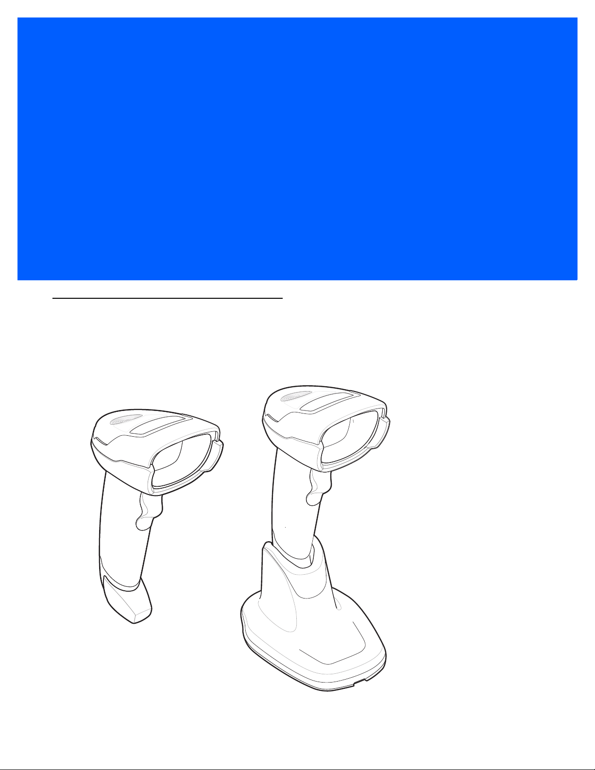
CHAPTER 1 GETTING STARTED
Introduction
The DS4308 and DS4308P combine superior 1D and 2D omnidirectional bar code scanning and transfer with
a light-weight, hands-free/hand-held design. The digital scanner’s gooseneck Intellistand seamlessly
accommodates both countertop and hand-held use. Whether in hands-free (presentation) or hand-held mode,
the digital scanner ensures comfort and ease of use for extended periods of time.
Figure 1-1
DS4308 and DS4308P Digital Scanner
Page 24

1 - 2 DS4308/DS4308P Digital Scanner Product Reference Guide
Interfaces
The DS4308 digital scanner supports:
•
USB connection to a host. The digital scanner autodetects a USB host and defaults to the HID keyboard
interface type. Select other USB interface types by scanning programming bar code menus.This
interface supports the following international keyboards (for Windows® environment): North America,
German, French, French Canadian, Spanish, Italian, Swedish, UK English, Portuguese-Brazilian, and
Japanese.
•
Standard RS-232 connection to a host. Scan bar code menus to set up communication of the digital
scanner with the host.
•
Connection to IBM 468X/469X hosts. Scan bar code menus to set up communication of the digital
scanner with the IBM terminal.
•
Keyboard Wedge connection to a host. The host interprets scanned data as keystrokes. Scan bar code
menus to set up communication of the digital scanner with the host. This interface supports the following
international keyboards (for Windows® environment): North America, German, French International,
French Canadian, French Belgian, Spanish, Italian, Swedish, UK English, Brazilian-Portuguese and
Japanese.
•
Configuration via 123Scan2.
Unpacking
Remove the digital scanner from its packing and inspect it for damage. If the scanner was damaged in transit,
contact support. See page xx for information. KEEP THE PACKING. It is the approved shipping container; use
this to return the equipment for servicing.
NOTE For a list of supported scanner functionality by communication protocol, see Appendix I, Communication
Protocol Functionality.
Page 25
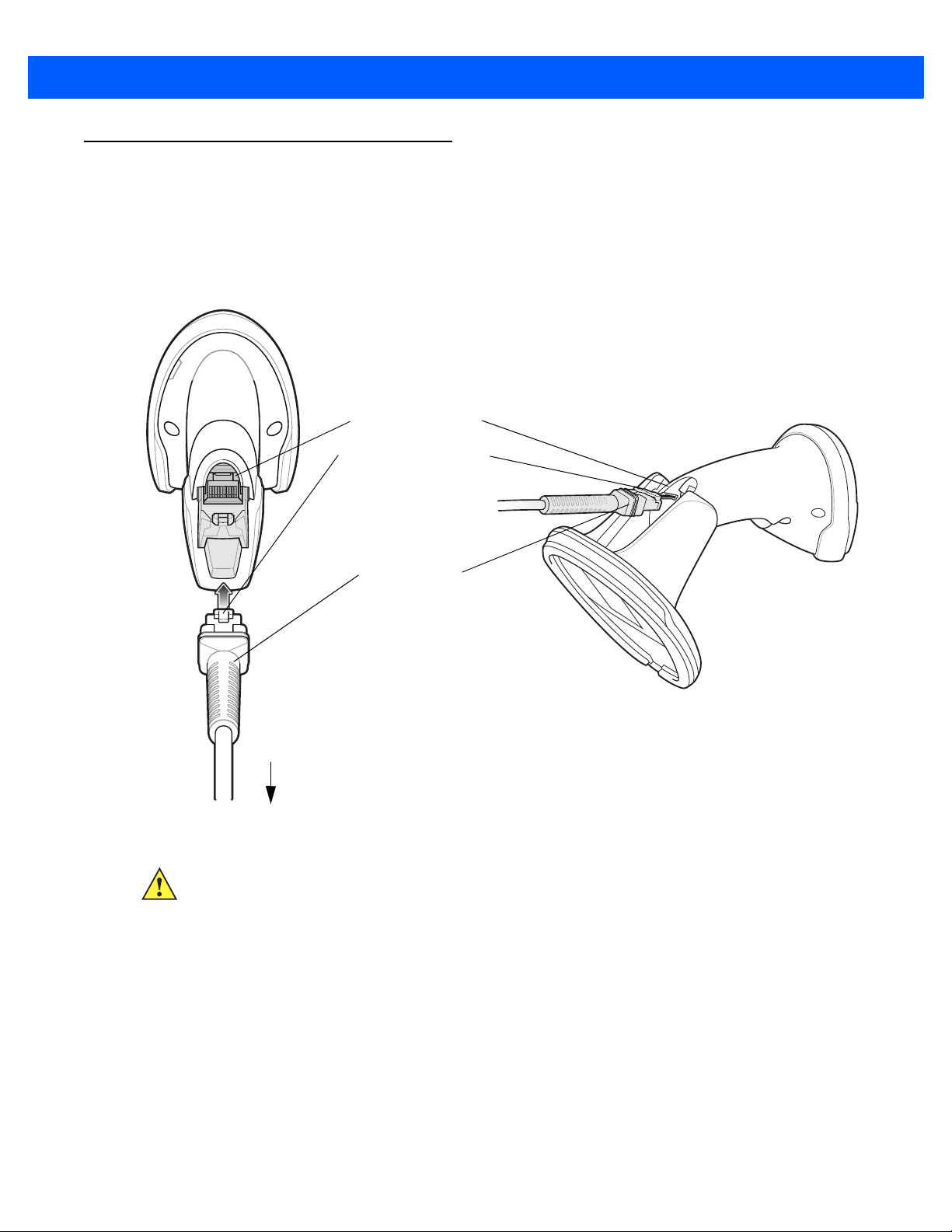
Setting Up the Digital Scanner
Interface cable
modular connector
To h o st
Cable interface port
Interface cable modular
connector clip
Installing the Interface Cable
1. Insert the interface cable modular connector into the interface cable port on the rear of the digital scanner
until you hear a click. For the DS4308P, tip the scanner forward in its base to best access the port.
Low/medium/high beeps sound, indicating the scanner is operational.
Getting Started 1 - 3
Figure 1-2
2. Gently tug the cable to ensure the connector is secure.
3. Connect the other end of the interface cable to the host (see the specific host chapter for information on
Installing the Cable - DS4308 and DS4308P
IMPORTANT Insert the cable into the cable interface port until a click sounds.
When connecting the DS4308 using a USB cable, a shielded connector cable is required (e.g., p/n
CBA-U21-S07ZAR). If upgrading an LS2208 or LS4208 to a DS4308, use the shielded connector
cable.
host connections).
Page 26
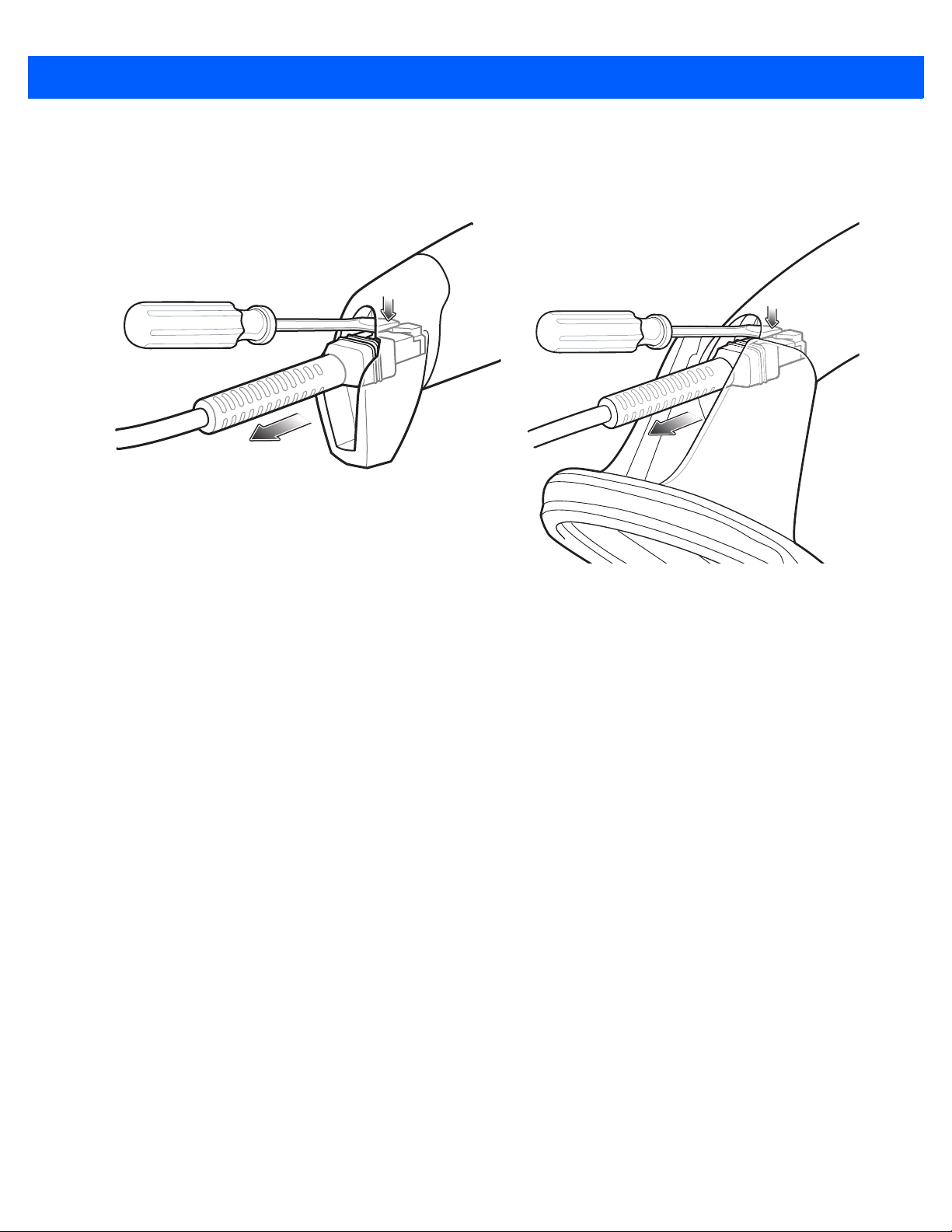
1 - 4 DS4308/DS4308P Digital Scanner Product Reference Guide
Removing the Interface Cable
1. Press the cable’s modular connector clip through the access slot in the digital scanner’s base. For the
DS4308P, tip the scanner forward in its base to best access the slot.
Figure 1-3
2. Carefully slide out the cable.
3. Follow the steps for Installing the Interface Cable to connect a new cable.
Removing the Cable - DS4308 and DS4308P
Connecting Power (if required)
If the host does not provide power to the digital scanner, connect an external power supply.
1. Plug the power supply into the power jack on the interface cable.
2. Plug the other end of the power supply into an AC outlet.
Configuring the Digital Scanner
To configure the digital scanner use the bar codes included in this manual, or use the 123Scan2 configuration
program. See Chapter 4, User Preferences & Miscellaneous Options, and Chapter 11, Symbologies for
information about programming the digital scanner using bar code menus. See Chapter 15, 123Scan and
Software Tools for information on using this configuration program. Also see each host-specific chapter to set
up connection to a specific host type.
Page 27

Accessories
The digital scanner ships with the DS4308 Quick Start Guide. The following required accessories must be
ordered:
•
Interface cable for the appropriate interface.
•
Shielded connector cable (e.g., p/n CBA-U21-S07ZAR) when connecting via USB. Refer to Solution
Builder for guidance about cables.
NOTE If upgrading an LS2208 or LS4208 to a DS4308, the shielded connector cable must be used.
•
Universal power supply, if the interface requires this.
•
Gooseneck Intellistand for hands-free operation of the DS4308.
•
Wall/table mount bracket for mounting the DS4308P.
For additional items, contact a local Zebra representative or business partner.
Getting Started 1 - 5
Page 28

1 - 6 DS4308/DS4308P Digital Scanner Product Reference Guide
Page 29
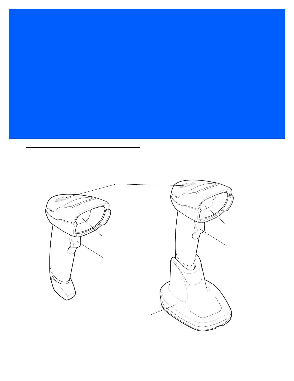
CHAPTER 2 DATA CAPTURE
LED
Trigger
Scan window
Trigger
Scan window
Pedestal base
Introduction
This chapter provides beeper and LED definitions, techniques involved in scanning bar codes, general
instructions and tips about scanning, and decode ranges.
Figure 2-1
Parts of the DS4308 and DS4308P
Page 30

2 - 2 DS4308/DS4308P Digital Scanner Product Reference Guide
Beeper Definitions
The digital scanner issues different beep sequences and patterns to indicate status. Table 2-1 defines beep
sequences that occur during both normal scanning and while programming the digital scanner.
Table 2-1
Standard Use
Low/medium/high beeps Power up.
Short beep, tone
programmable
4 long low beeps Transmission error.
5 low beeps Conversion or format error.
Low/low/low/extra low beeps RS-232 receive error.
High beep The digital scanner detected a <BEL> character over RS-232.
Parameter Menu Scanning
Low/high beeps Input error; incorrect bar code, programming sequence, or
High/low beeps Keyboard parameter selected. Enter value using numeric bar codes.
High/low/high/low beeps Successful program exit with change in parameter setting.
ADF Programming
Beeper Definitions
Beeper Sequence Indication
A bar code symbol was decoded (if decode beeper is enabled).
Cancel
scanned.
Low/low beeps Enter another alphabetic character or scan the
Low/high/high beeps All rules are deleted.
Low/high/low/high beeps Out of rule memory. Erase some existing rules, then try to save rule again.
Low/high/low beeps Cancel rule entry. Rule entry mode exited because of an error or the user
asked to exit rule entry.
Low/high beeps Entry error, wrong bar code scanned, or criteria/action list is too long for a rule.
Re-enter criterion or action.
Low beep Delete last saved rule. The current rule is left intact.
High/high beeps ADF criteria or action is expected. Enter another criterion or action, or scan the
Save Rule
High/low/low beeps All criteria or actions cleared for current rule, continue entering rule.
High/low/high/low beeps Rule saved. Rule entry mode exited.
Code 39 Buffering
Low/high/low beeps The Code 39 buffer was erased or there was an attempt to clear or transmit an
empty buffer.
High/low beeps New Code 39 data was entered into the buffer.
3 long high beeps Code 39 buffer is full.
bar code.
End of Message
bar code.
Page 31

Data Capture 2 - 3
Table 2-1
High/low/high beeps The Code 39 buffer was erased.
Low/high beeps A successful transmission of buffered data.
Macro PDF
2 low beeps
2 long low beeps
3 long low beeps Out of memory. There is not enough buffer space to store the current MPDF
4 long low beeps Bad symbology. Scanned a 1D or 2D bar code in a MPDF sequence, a
5 long low beeps Flushing MPDF buffer.
Low/high beeps Flushing an already empty MPDF buffer.
Fast warble beep Aborting MPDF sequence.
Host Specific
Beeper Definitions (Continued)
Beeper Sequence Indication
MPDF sequence buffered.
File ID error. A bar code not in the current MPDF sequence was scanned.
symbol.
duplicate MPDF label, a label in an incorrect order, or trying to transmit an
empty or illegal MPDF field.
USB only
Low/medium/high beeps
upon scanning a USB device
type
Low/medium/high beeps
occur more than once
RS-232 only
1 short high beep A <BEL> character is received and Beep on <BEL> is enabled.
Communication with the host must be established before the digital scanner
can operate at the highest power level.
The USB host can put the digital scanner in a state where power to the
scanner is cycled on and off more than once. This is normal and usually
happens when the PC cold boots.
Page 32

2 - 4 DS4308/DS4308P Digital Scanner Product Reference Guide
LED Definitions
In addition to beep sequences, the digital scanner uses a two-color LED to indicate status. Table 2-2 defines
LED colors that display during scanning.
Table 2-2
Hand-Held Scanning Standard Use
Green A bar code was successfully decoded.
Red Transmission error, conversion or format error, or RS-232 receive error.
Off No power is applied to the digital scanner, or the scanner is on and ready to scan.
Hands-Free (Presentation) Scanning Standard Use
Green The scanner is on and ready to scan.
Momentarily Off A bar code was successfully decoded.
Red Transmission error, conversion or format error, or RS-232 receive error.
Off No power is applied to the digital scanner, or the scanner is in low power mode.
DS4308-XD Only: Hands-Free (Presentation) Scanning Standard Use
Green Momentarily On A bar code was successfully decoded.
Red Transmission error, conversion or format error, or RS-232 receive error.
Off No power is applied to the digital scanner, the scanner is in low power mode, or a
Standard LED Definitions
LED Indication
scan session in progress.
Parameter Programming
Green Number expected. Enter value using numeric bar codes.
Successful program exit with change in parameter setting.
Red Input error: incorrect bar code, programming sequence, or Cancel scanned.
Firmware Update
Red, alternating between
solid and fast blinking
Firmware download is completing (user should wait for this indicator to complete
before using the scanner). This indicator is followed by a low/medium/high power
up beep.
Page 33

Data Capture 2 - 5
Table 2-2
ADF Programming
Green Enter another digit. Add leading zeros to the front if necessary.
Blinking Green Enter another criterion or action, or scan the
Green after Blinking Rule saved. Rule entry mode exited.
Red Out of rule memory. Erase some existing rules, then try to save rule again.
Standard LED Definitions (Continued)
LED Indication
Enter another alphabetic character or scan the
All criteria or actions cleared for current rule, continue entering rule.
Delete last saved rule. The current rule is left intact.
All rules deleted.
Cancel rule entry. Rule entry mode exited because of an error or the user asked to
exit rule entry.
Entry error, wrong bar code scanned, or criteria/action list is too long for a rule.
Re-enter criterion or action.
End of Message
Save Rule
bar code.
bar code.
Page 34

2 - 6 DS4308/DS4308P Digital Scanner Product Reference Guide
Stand base
Wingnut
One piece scanner
“cup” with flexible
“gooseneck”
Scanning
The DS4308 digital scanner is in hands-free (presentation) mode when it is placed in the gooseneck
Intellistand. The DS4308P is in hands-free (presentation) mode when it is placed on the countertop. In this
mode, the digital scanner operates in continuous (constant-on) mode, where it automatically decodes a bar
code presented in its field of view.
When the digital scanner is not used for a user-definable period of time, it enters a low power mode in which
the LEDs are turned off or illumination blinks at a low duty cycle until the digital scanner detects an image
change (e.g. motion).
Scanning in Hands-Free (Presentation) Mode - DS4308
The optional stand adds greater flexibility to DS4308 scanning operation. When the scanner is seated in the
stand’s “cup,” the scanner’s built-in sensor places the scanner in hands-free (presentation) mode. When the
scanner is removed from the stand, it automatically switches to its programmed hand-held triggered mode.
Assemble the Stand
To assemble the stand:
1. Unscrew the wing nut from the bottom of the one piece scanner “cup.”
Figure 2-2
2. Fit the bottom of the gooseneck piece into the opening on the top of the stand base.
3. Tighten the wing nut underneath the base to secure the cup and neck piece to the base.
4. Bend the neck to the desired position for scanning.
Assembling the Stand
Page 35

Data Capture 2 - 7
Two screw-mount holes
Double-sided tape areas
(3 places)
dimensions = 1” x 2”)
Mounting the Stand (optional)
You can attach the base of the scanner’s stand to a flat surface using two screws or double-sided tape (not
provided).
Figure 2-3
Mounting the Stand
Screw Mount
1. Position the assembled base on a flat surface.
2. Screw one #10 wood screw into each screw-mount hole until the base of the stand is secure (see Figure
2-3).
Tape Mount
1. Peel the paper liner off one side of each piece of tape and place the sticky surface over each of the three
rectangular tape holders.
2. Peel the paper liner off the exposed sides of each piece of tape and press the stand on a flat surface until
it is secure (see Figure 2-3).
Page 36

2 - 8 DS4308/DS4308P Digital Scanner Product Reference Guide
Scanning with the Stand
When the digital scanner is placed in the gooseneck Intellistand it operates in continuous (constant-on) mode,
where it automatically decodes a bar code presented in its field of view.
To operate the scanner in the stand:
1. Ensure the scanner is properly connected to the host (see the appropriate host chapter for information on
host connections).
2. Insert the scanner in the gooseneck Intellistand by placing the front of the scanner into the stand’s “cup.”
Figure 2-4
3. Adjust the scan angle by bending the stand’s flexible “gooseneck” body.
4. Present the bar code. Upon successful decode, the scanner beeps and the LED momentarily shuts off. For
Inserting the Scanner in the Gooseneck Intellistand
more information about beeper and LED definitions, see Table 2-1 and Table 2-2.
Page 37

Data Capture 2 - 9
Scanning in Hands-Free (Presentation) Mode - DS4308P
Placing the DS4308P on the countertop or in the optional wall mount puts the scanner in hands-free
(presentation) mode. It operates in continuous (constant-on) mode, where it automatically decodes a bar code
presented in its field of view. Lifting the scanner places it in its programmed hand-held triggered mode.
DS4308P Wall Mounting
The optional wall mount allows mounting the DS4308P to a wall for scanning. Place the mount at the desired
location and secure with two screws (not provided).
Figure 2-5
Slide the base of the DS4308P into the stand
Mounting the DS4308P Wall Mount
Figure 2-6
Inserting the DS4308P into the Wall Mount
Page 38

2 - 10 DS4308/DS4308P Digital Scanner Product Reference Guide
DS4308P Hands-Free Scanning
To operate the DS4308P in hands-free mode:
1. Ensure the scanner is properly connected to the host (see the appropriate host chapter for information on
host connections).
2. Place the scanner on the countertop or in the optional wall mount.
3. Adjust the scan angle by swiveling the scanner forward or backward in its base.
Figure 2-7
4. Present the bar code to the scanner. The scanner turns on illumination. Upon successful decode, the
Adjusting the DS4308P
scanner beeps and the LED momentarily shuts off. For more information about beeper and LED
definitions, see Table 2-1 and Table 2-2.
Figure 2-8
Scanning with the DS4308P
Page 39

Scanning in Hand-Held Mode
Pick up the digital scanner. The aiming dot displays.
1. Ensure the aiming dot is centered on the bar code. See Aiming below.
Data Capture 2 - 11
Figure 2-9
2. Press and hold the trigger until either:
a. The digital scanner reads the bar code. The digital scanner beeps, the LED flashes, and the aiming dot
b. The digital scanner does not read the bar code and the aiming dot turns off.
3. Release the trigger.
Centering the Aiming Dot on the Bar Code - DS4308 and DS4308P
turns off.
Or
Aiming
When scanning, the digital scanner projects a red LED dot which allows positioning the bar code within its field
of view. See Decode Ranges on page 2-13 for the proper distance to achieve between the digital scanner and
a bar code.
Figure 2-10
If necessary, the digital scanner turns on its red illumination LEDs to illuminate the target bar code.
Aiming Dot
Page 40

2 - 12 DS4308/DS4308P Digital Scanner Product Reference Guide
1D bar code
2D bar code
To scan a barcode, center the symbol and ensure the entire symbol is within the rectangular area formed by
the illumination LEDs.
Figure 2-11
Scanning Orientation with Aiming Dot
The digital scanner can also read a bar code presented within the aiming dot not centered. The top examples
in Figure 2-12 show acceptable aiming options, while the bottom examples can not be decoded.
Figure 2-12
Figure 2-13
Acceptable Aiming
Incorrect Aiming
The aiming dot is smaller when the digital scanner is closer to the symbol and larger when it is farther from the
symbol. Scan symbols with smaller bars or elements (mil size) closer to the digital scanner, and those with
larger bars or elements (mil size) farther from the digital scanner.
The digital scanner beeps to indicate that it successfully decoded the bar code. For more information on
beeper and LED definitions, see Table 2-1 and Table 2-2.
Page 41

Decode Ranges
Data Capture 2 - 13
Table 2-3
Bar Code
Code 128 2.0 mil N/A N/A N/A N/A 0.6 / 1.5 3.0 / 7.6
Code 39 2.0 mil N/A N/A N/A N/A 0.5 / 1.3 3.0 / 7.6
100% UPC 13.0 mil 0.0 / 0.0 28.0 / 71.1 0.0 / 0.0 16.5 / 41.9 N/A N/A
PDF417 4.0 mil N/A N/A N/A N/A 0.5 / 1.3 3.3 / 8.4
MicroPDF 4.0 mil N/A N/A 1.0 / 2.5 4.7 / 11.9 N/A N/A
DS4308 Decode Ranges
Type
Symbol
Density
3.0 mil N/A N/A 1.0 / 2.5 3.0 / 7.6 0.4 / 1.0 3.3 / 8.4
3.0 mil 1.5 / 3.8 5.4 / 13.7 0.5 / 1.3 5.8 / 14.6 0.2 / 0.5 3.8 / 9.7
5.0 mil 0.0 / 0.0 11.0 / 27.9 0.0 / 0.0 10.0 / 25.4 0.1 / 0.3 4.7 / 11.9
20.0 mil 0.0 / 0.0 53.0 / 134.6 0.0 / 0.0 30.0 / 76.2 N/A N/A
5.0 mil N/A N/A N/A N/A 0.1 / 0.3 3.6 / 9.1
6.6 mil 1.1 / 2.8 8.0 / 20.3 0.2 / 0.5 7.8 / 19.7 0.1 / 0.3 4.1 / 10.4
Typical Working Ranges
DS4308-SR
Near
(in / cm)
Far
(in / cm)
Near
(in / cm)
DS4308-HD
Far
(in / cm)
Typical Working Ranges
Near
(in / cm)
DS4308-XD
(in / cm)
Typical Working Ranges
Far
5.0 mil N/A N/A N/A N/A 0.2 / 0.5 3.1 / 7.9
Data Matrix 4 mil N/A N/A N/A N/A 0.7 / 1.8 3.0 / 7.6
5 mil N/A N/A 1.2 / 3.0 3.5 / 8.9 0.4 / 1.0 3.4 / 8.6
7.5 mil N/A N/A 1.0 / 2.5 6.5 / 16.5 N/A N/A
10.0 mil 2.0 / 5.1 9.0 / 22.9 0.8 / 1.9 8.2 / 20.8 0.1 / 0.3 4.6 / 11.7
QR Code 10.0 mil 1.1 / 2.8 8.5 / 21.6 0.0 / 0.0 7.0 / 17.8 0.0 / 0.0 4.5 / 11.4
20.0 mil 0.9 / 2.3 16.2 / 41.1 0.5 / 1.3 11.0 / 27.9 N/A N/A
Page 42

2 - 14 DS4308/DS4308P Digital Scanner Product Reference Guide
Page 43

CHAPTER 3 MAINTENANCE & TECHNICAL
SPECIFICATIONS
Introduction
This chapter provides suggested digital scanner maintenance, troubleshooting, technical specifications, and
signal descriptions (pinouts).
Maintenance
General Scanner Maintenance
Cleaning the scan window is required. A dirty window can affect scanning accuracy.
•
Do not allow abrasive material to touch the window.
•
Remove any dirt particles with a damp cloth.
•
Wipe the window using a tissue moistened with approved cleanser (listed below).
•
Do not spray water or other cleaning liquids directly into the window.
In addition to the cleaning requirements above, healthcare configurations of the scanner (DS4308-HC) may
require additional maintenance.
Healthcare Scanner Maintenance
The DS4308-HC design allows safe cleansing of the product plastics with a variety of cleaning products and
disinfectants. If required, wipe the digital scanner with the following list of approved cleansers:
•
Isopropyl alcohol
•
Bleach/sodium hypochlorite
•
Hydrogen peroxide
•
Gentle dish soap and water
IMPORTANT Cleansers that contain active ingredients not listed above should not be utilized on the
DS4308-HC digital scanner.
Page 44

3 - 2 DS4308/DS4308P Digital Scanner Product Reference Guide
Daily Cleaning and Disinfecting
Following are the cleaning and disinfecting instructions for environments that require daily or more frequent
cleaning to prevent the spread of germs, including healthcare workers who need to disinfect their scanner after
each patient visit and retail and other shift workers who share devices.
1. Dampen a soft cloth with one of the approved cleaning agents listed above or use pre-moistened wipes.
2. Gently wipe all surfaces, including the front, back, sides, top and bottom. Never apply liquid directly to the
scanner. Be careful not to let liquid pool around the scanner window, trigger, cable connector or any other
area on the device.
3. Be sure to clean the trigger and in between the trigger and the housing (use a cotton-tipped applicator to
reach tight or inaccessible areas).
4. Immediately dry the scanner window after cleaning with a soft non-abrasive cloth to prevent streaking.
5. Allow the unit to air dry before use.
Monthly 'Deep Cleaning' Maintenance
Keep your scanner in good working order with a regular comprehensive cleaning routine to remove the natural
build-up of dirt that occurs with everyday use on connectors and the scanner exit window as well as, the main
surfaces of the device.
1. Housing: Follow the instructions for daily cleaning and disinfecting above to give the housing a general
cleaning.
2. Scanner window: Wipe the scanner window with a lens tissue or other material suitable for cleaning optical
material such as eyeglasses.
3. Scanner connector:
a. Dip the cotton portion of a cotton-tipped applicator in isopropyl alcohol.
b. Rub the cotton portion of the cotton-tipped applicator back-and-forth across the connector on the
scanner. Do not leave any cotton residue on the connector.
c. Repeat at least 3 times.
d. Use the cotton-tipped applicator dipped in alcohol to remove any grease and dirt near the connector
area.
e. Use a dry cotton tipped applicator and repeat steps c, d and e (do not apply alcohol as directed in any
of these steps).
Page 45

Troubleshooting
Maintenance & Technical Specifications 3 - 3
Table 3-1
The aiming pattern does not
appear when pressing the
trigger.
Digital scanner emits aiming
pattern, but does not
decode the bar code.
Troubleshooting
Problem Possible Causes Possible Solutions
No power to the digital scanner. If the configuration requires a power
supply, re-connect the power supply.
Incorrect host interface cable is
used.
Interface/power cables are loose. Re-connect cables.
Digital scanner is disabled. For IBM 468x and USB IBM hand-held,
If using RS-232 Nixdorf B mode,
CTS is not asserted.
Aiming pattern is disabled. Enable the aiming pattern. See
Digital scanner is not programmed
for the correct bar code type.
Connect the correct host interface cable.
IBM table-top, and OPOS modes, enable
the digital scanner via the host interface.
Otherwise, see the technical person in
charge of scanning.
Assert CTS line.
Hand-Held Decode Aiming Pattern on
page 4-23
Program the digital scanner to read that
type of bar code. See
Symbologies
.
Chapter 11,
.
Bar code symbol is unreadable. Scan test symbols of the same bar code
type to determine if the bar code is
defaced.
The symbol is not completely
inside aiming pattern.
Distance between digital scanner
and bar code is incorrect.
Move the symbol completely within the
aiming pattern.
Move the symbol completely within the
field of view (AIM pattern does NOT
define FOV)
Move the scanner closer to or further from
the bar code. See
page 2-13
.
Decode Ranges on
Page 46

3 - 4 DS4308/DS4308P Digital Scanner Product Reference Guide
Table 3-1
Digital scanner decodes bar
code, but does not transmit
the data to the host.
Troubleshooting (Continued)
Problem Possible Causes Possible Solutions
Digital scanner is not programmed
for the correct host type.
Interface cable is loose. Re-connect the cable.
If the digital scanner emits 4 long
low beeps, a transmission error
occurred.
This occurs if a unit is not properly
configured or connected to the
wrong host type.
If the digital scanner emits 5 low
beeps, a conversion or format error
occurred.
If the digital scanner emits
low/high/low beeps, it detected an
invalid ADF rule.
If the digital scanner emits high/low
beeps, the scanner is buffering
Code 39 data.
Scan the appropriate host type
programming bar code. See the chapter
corresponding to the host type.
Set the scanner's communication
parameters to match the host's setting.
Configure the digital scanner's conversion
parameters properly.
Program the correct ADF rules. Refer to
the Advanced Data Formatting
Programmer Guide.
Normal scanning a Code 39 bar code and
the Code 39 Buffering option is enabled.
Host displays scanned data
incorrectly.
Digital scanner emits short
low/short medium/short high
beep sequence (power-up
beep sequence) more than
once.
Digital scanner emits 4 short
high beeps during decode
attempt.
Digital scanner emits
Low/low/low/extra low
beeps when not in use.
Digital scanner is not programmed
to work with the host.
The USB bus may put the digital
scanner in a state where power to
the scanner is cycled on and off
more than once.
Digital scanner has not completed
USB initialization.
RS-232 receive error. Normal during host reset. Otherwise, set
Scan the appropriate host type
programming bar code.
For RS-232, set the digital scanner's
communication parameters to match the
host's settings.
For a Keyboard Wedge configuration,
program the system for the correct
keyboard type, and turn off the CAPS
LOCK key.
Program the proper editing options (e.g.,
UPC-E to UPC-A Conversion).
Normal during host reset.
Wait several seconds and scan again.
the digital scanner's RS-232 parity to
match the host setting.
Page 47

Maintenance & Technical Specifications 3 - 5
Table 3-1
Digital scanner emits
low/high beeps during
programming.
Digital scanner emits
low/high/low/high beeps
during programming.
Digital scanner emits
low/high/low beeps.
Troubleshooting (Continued)
Problem Possible Causes Possible Solutions
Input error, incorrect bar code or
Cancel
Out of host parameter storage
space.
Out of memory for ADF rules. Reduce the number of ADF rules or the
During programming, indicates out
of ADF parameter storage space.
Clearing Code 39 buffer. Normal when scanning the Code 39
ADF transmit error. Refer to the Advanced Data Formatting
Invalid ADF rule is detected. Refer to the Advanced Data Formatting
bar code was scanned.
Scan the correct numeric bar codes within
range for the parameter programmed.
Scan
Default Parameters on page 4-5
number of steps in the ADF rules.
Erase all rules and re-program with
shorter rules.
Buffering
attempt to transmit an empty Code 39
buffer.
Guide for information.
Guide for information.
Clear Buffer
bar code or upon
.
Digital scanner emits a
power-up beep after
changing USB host type.
Digital scanner emits one
high beep when not in use.
Digital scanner emits
frequent beeps.
The USB bus re-established power
to the digital scanner.
In RS-232 mode, a <BEL>
character was received and Beep
on <BEL> option is enabled.
No power to the scanner. Check the system power. If the
Incorrect host interface cable is
used.
Interface/power cables are loose. Check for loose cable connections and
Normal when changing USB host type.
Normal when
and the digital scanner is in RS-232
mode.
configuration requires a power supply,
re-connect the power supply.
Verify that the correct host interface cable
is used. If not, connect the correct host
interface cable.
re-connect cables.
Beep on <BEL>
is enabled
Page 48

3 - 6 DS4308/DS4308P Digital Scanner Product Reference Guide
Table 3-1
Digital scanner emits five
long low beeps after a bar
code is decoded.
Troubleshooting (Continued)
Problem Possible Causes Possible Solutions
NOTE If after performing these checks the digital scanner still experiences problems, contact the distributor or
call support.
Conversion or format error was
detected.
The scanner’s conversion
parameters are not properly
configured.
Conversion or format error was
detected.
An ADF rule was set up with
characters that can't be sent for the
host selected.
Conversion or format error was
detected.
A bar code was scanned with
characters that can't be sent for
that host.
Ensure the scanner’s conversion
parameters are properly configured.
Change the ADF rule, or change to a host
that can support the ADF rule.
Change the bar code, or change to a host
that can support the bar code.
Report Software Version Bar Code
When contacting support, a support representative may ask you to scan the bar code below to determine the
version of software installed in the digital scanner.
Report Software Version
Page 49

Technical Specifications
Maintenance & Technical Specifications 3 - 7
Table 3-2
Physical Characteristics
Dimensions
Weight
Power 5 VDC +/- 10% @ 360 mA (RMS typical)
Performance Characteristics
Light Source Aiming pattern: 617 nm LED
Field of View
(Vertical x Horizontal)
Roll
Pitch
Yaw
Technical Specifications
Item Description
DS4308
DS4308P
(without cable)
DS4308
DS4308P
6.48 in. H x 3.86 in. L x 2.64 in. W
(16.5 cm H x 9.8 cm L x 6.7 cm W)
8.15 in. H x 5.18 in. L x 3.74 in. W
(20.7 cm H x 13.15 cm L x 9.5 cm W)
5.71 oz. (162 g)
10.6 oz. (300 g)
Illumination: 660 nm LEDs
36º (H) x 22.5º (V)
0 - 360º
+/- 65º or greater
+/- 60º or greater
Symbology Decode Capability
1D UPC/EAN, UPC/EAN with supplementals, Bookland EAN, ISSN, UCC Coupon
Extended Code, Code 128, GS1-128, ISBT 128, ISBT Concatenation, Code 39,
Code 39 Full ASCII, Trioptic Code 39, Code 32, Code 93, Code 11, Interleaved 2
of 5, Discrete 2 of 5, Codabar, MSI, Chinese 2 of 5, Matrix 2 of 5, Korean 3 of 5,
GS1 DataBar variants
2D PDF417, MicroPDF417, Composite Codes, TLC-39, Data Matrix, GS1 Data
Matrix, Maxicode, QR Code, GS1 QR Code, MicroQR, Aztec, Han Xin
Postal US Postnet, US Planet, UK Postal, Japan Postal, Australia Post, Royal Mail 4
State Customer, KIX Code (Dutch), UPU 4 State Postal FICS (Post US4), USPS
4 State Postal (Post US3), Mailmark
Typical Working Distance See
Motion Tolerances Up to 30 in. (76.2) cm per second
Decode Ranges on page 2-13
.
Page 50

3 - 8 DS4308/DS4308P Digital Scanner Product Reference Guide
Table 3-2
Interfaces Supported USB, RS-232, RS-485 (IBM 46xx), keyboard wedge, SSI
Minimum Resolution Standard Range (SR) Configuration
User Environment
Technical Specifications (Continued)
Item Description
The scanner supports the following protocols over USB: HID Keyboard (default
mode), SNAPI, COM Port Emulation, IBM SurePOS (Yellowstone) (IBM
Hand-held, IBM Table-top, OPOS), USB CDC, SSI over USB CDC
The scanner supports the following protocols over RS232: Standard,
Wincor-Nixdorf, ICL, Fujitsu, Olivetti, Omron, CUTE
Code 39 4 mil
UPC 60% 7.8 mil
PDF417 5 mil
Data Matrix 7.5 mil
High Density (HD) Configuration
Code 39 3 mil
UPC 60% 7.8 mil
PDF417 4 mil
Data Matrix 5 mil
Operating Temperature 32º F to 122º F (0º C to 50º C)
Storage Temperature -40º F to 158º F (-40º C to 70º C)
Humidity 5% to 95%, non-condensing
Drop Specifications
DS4308
DS4308P
Environmental Sealing IP42
Ambient Light Immunity Immune to normal indoor lighting up to 1600 Lux.
Accessories
DS4308 Hands-Free
Option
DS4308P Mounting
Option
Power Supplies Power supplies are available for applications that do not supply power over the
Withstands multiple 6 ft. (1.8 m) drops to concrete
Withstands multiple 5 ft. (1.5 m) drops to concrete.
Immune to sunlight up to 86,000 Lux.
Gooseneck Intellistand
Wall/table mount bracket
host cable.
Page 51

Digital Scanner Signal Descriptions
Cable interface port
Interface cable
modular connector
Bottom of
scanner
PIN 1
PIN 10
Maintenance & Technical Specifications 3 - 9
Figure 3-1
Digital Scanner Cable Pinouts
Page 52

3 - 10 DS4308/DS4308P Digital Scanner Product Reference Guide
The signal descriptions in Table 3-3 apply to the connectors on the DS4308 digital scanner and are for
reference only.
Table 3-3
1
2
3
4
5
6
7
8
9
10
SHELL
DS4308 Digital Scanner Signal Pin-outs
Pin USB RS-232 Keyboard Wedge IBM
Short to Pin 6 Reserved 1M Resistor to Pin 8 2M Resistor to Pin 8
Power Power Power Power
Ground Ground Ground Ground
Reserved TXD KBD_CLK IBM_TXD
D + RXD TERM_DATA IBM_RXD
Short to Pin 1 RTS KBD_DATA IBM_DIR
D - CTS TERM_CLK Reserved
Reserved Reserved 1M Resistor to Pin 1 2M Resistor to Pin 1
EAS EAS EAS EAS
EAS EAS EAS EAS
Shield Shield Shield Shield
Page 53

CHAPTER 4 USER PREFERENCES &
*High Volume
(0)
Feature/Option
* Indicates Default
Option Value
MISCELLANEOUS OPTIONS
Introduction
You can program the digital scanner to perform various functions, or activate different features. This chapter
describes each user preference feature and provides programming bar codes for selecting these features.
The digital scanner ships with the settings shown in Table 4-1 on page 4-2 (also see Appendix A, Standard
Default Parameters for all defaults). If the default values suit requirements, programming is not necessary.
To set feature values, scan a single bar code or a short bar code sequence. The settings are stored in
non-volatile memory and are preserved even when the digital scanner is powered down.
NOTE Most computer monitors allow scanning the bar codes directly on the screen. When scanning from the
screen, be sure to set the document magnification to a level where you can see the bar code clearly, and
bars and/or spaces are not merging.
If not using a USB cable, select a host type (see each host chapter for specific host information) after the
power-up beeps sound. This is only necessary upon the first power-up when connected to a new host.
To return all features to default values, see Default Parameters on page 4-5. Throughout the programming bar
code menus, asterisks indicate (
*) default values.
Page 54

4 - 2 DS4308/DS4308P Digital Scanner Product Reference Guide
Scanning Sequence Examples
In most cases, scanning one bar code sets the parameter value. For example, to set the beeper tone to high,
scan the High Frequency (beeper tone) bar code listed under Beeper Tone on page 4-10. The digital scanner
issues a fast warble beep and the LED turns green, signifying a successful parameter entry.
Other parameters, such as Serial Response Time-Out or Data Transmission Formats, require scanning
several bar codes. See these parameter descriptions for this procedure.
Errors While Scanning
Unless otherwise specified, to correct an error during a scanning sequence, just re-scan the correct parameter.
User Preferences/Miscellaneous Options Parameter Defaults
Table 4-1 lists defaults for user preferences parameters. To change the default values:
•
Scan the appropriate bar codes in this guide. These new values replace the standard default values in
memory. To recall the default parameter values, see Default Parameters on page 4-5.
•
Configure the digital scanner using the 123Scan2 configuration program (see Chapter 15, 123Scan and
Software Tools).
NOTE See Appendix A, Standard Default Parameters for all user preferences, hosts, symbologies, and
miscellaneous default parameters.
Table 4-1
User Preferences
Set Default Parameter Restore Defaults
Parameter Bar Code Scanning 236 ECh Enable
Beep on Decode 56 38h Enable
Direct Decode Indicator 859 F2h 5Bh Disable
Beeper Volume 140 8Ch High
Beeper Tone 145 91h Medium
User Preferences Parameter Defaults
Parameter
Parameter
Number
1
SSI
Number
2
Default
Page
Number
4-5
4-6
4-7
4-8
4-9
4-10
Beeper Duration 628 F1h 74h Medium
Suppress Power Up Beeps 721 F1h D1h Do Not Suppress
Decode Pager Motor
(DS4308-HC and DS4308-XD)
1. Parameter number decimal values are used for programming via RSM commands.
2. SSI number hex values are used for programming via SSI commands.
613 F1h 65h Disable
4-11
4-11
4-12
Page 55

User Preferences & Miscellaneous Options 4 - 3
Table 4-1
Decode Pager Motor Duration
User Preferences Parameter Defaults (Continued)
Parameter
Parameter
Number
1
626 F1h 72h 150 msec
SSI
Number
2
(DS4308-HC and DS4308-XD)
Night Mode Trigger (DS4308-HC Only) 1215 F8h 04h BFh Enable
Night Mode Toggle (DS4308-HC Only) N/A N/A N/A
Low Power Mode 128 80h Disable
Time Delay to Low Power Mode 146 92h 1 Hour
Hand-Held Trigger Mode 138 8Ah Auto Aim
Hands-Free Mode 630 F1h 76h Enable
Presentation Performance Mode 650 F1h 8Ah Standard
Hands-Free/Hand-Held Auto Switching
(DS4308P Only)
N/A N/A Auto Aim in Hand-Held,
Auto Switching to
Hands-Free Enabled
Hand-Held Decode Aiming Pattern 306 F0h 32h Enable
Hands-Free (Presentation) Decode
Aiming Pattern
590 F1h 4Eh Enable Hands-Free
(Presentation) Decode
Aiming Pattern on PDF
DS4308-XD only
Enable Hands-Free
Decode Aiming Pattern
Default
Page
Number
4-12
4-15
4-15
4-16
4-17
4-19
4-20
4-21
4-22
4-23
4-24
:
Hands-Free Motionless Timeout
745 F1h E9h 2.0 seconds
(DS4308P Only)
Motion Detect Range (DS4308P Only) 827 F2h 3Bh Full
Picklist Mode 402 F0h 92h Disabled Always
Continuous Bar Code Read 649 F1h 89h Disable
Unique Bar Code Reporting 723 F1h D3h Enable
Decode Session Timeout 136 88h 9.9 Sec
Timeout Between Decodes, Same
137 89h 0.5 Sec
Symbol
Timeout Between Decodes, Different
144 90h 0.1 sec
Symbols
Fuzzy 1D Processing 514 F1h 02h Enable
Decode Mirror Images (Data Matrix Only) 537 F1h 19h Auto
Mobile Phone/Display Mode 716 F1h CCh Normal
1. Parameter number decimal values are used for programming via RSM commands.
2. SSI number hex values are used for programming via SSI commands.
4-24
4-25
4-26
4-27
4-27
4-28
4-28
4-29
4-29
4-30
4-31
Page 56

4 - 4 DS4308/DS4308P Digital Scanner Product Reference Guide
Table 4-1
User Preferences Parameter Defaults (Continued)
Parameter
Parameter
Number
1
SSI
Number
2
Default
PDF Prioritization 719 F1h CFh Disable
PDF Prioritization Timeout 720 F1h D0h 200 ms
Presentation Mode Field of View 609 F1h 61h Full
Decoding Illumination 298 F0h 2Ah Enable
Post Decode Illumination
809 F2h 29h Always Off
(DS4308P Only)
Illumination Brightness 669 F1h 9Dh High
DS4308-XD only
Low Light Scene Detection 810 F2h 2Ah Dim Illumination Low
Light Assist Scene
Detection
Motion Tolerance (Hand-Held Trigger
858 F2h 5Ah Less Motion Tolerance
Mode Only)
Movement Sensitivity (DS4308P Only) 1300 F8h 05h 14h Medium
Page
Number
4-32
4-32
4-33
4-33
4-34
4-35
: Low
4-36
4-37
4-38
Object Detection Method
857 F2h 59h IR Sensor Detection
(DS4308P Only)
Miscellaneous Options
Add an Enter Key N/A N/A N/A
Transmit Code ID Character 45 2Dh None
Prefix Value 99, 105 63h, 69h 7013 <CR><LF>
Suffix 1 Value
Suffix 2 Value
98, 104
100, 106
62h, 68h
64h, 6Ah
7013 <CR><LF>
Scan Data Transmission Format 235 EBh Data as is
FN1 Substitution Values 103, 109 67h, 6Dh 7013 <CR><LF>
Transmit “No Read” Message 94 5E Disable
Unsolicited Heartbeat Interval 1118 F8h 04h 5Eh Disable
Dump Scanner Parameters N/A N/A N/A
1. Parameter number decimal values are used for programming via RSM commands.
2. SSI number hex values are used for programming via SSI commands.
4-39
4-40
4-41
4-42
4-42
4-43
4-44
4-45
4-46
4-47
Page 57

User Preferences
Default Parameters
The digital scanner can be reset to two types of defaults: factory defaults or custom defaults. Scan the
appropriate bar code below to reset the digital scanner to its default settings and/or set the digital scanner’s
current settings as the custom default.
•
Restore Defaults - Resets all default parameters as follows:
• If custom default values were configured (see Write to Custom Defaults), the custom default values
are set for all parameters each time the Restore Defaults bar code below is scanned.
• If no custom default values were configured, the factory default values are set for all parameters each
time the Restore Defaults bar code below is scanned. (For factory default values, see Appendix A,
Standard Default Parameters.)
•
Set Factory Defaults - Scan the Set Factory Defaults bar code below to eliminate all custom default
values and set the digital scanner to factory default values (For factory default values, see Appendix A,
Standard Default Parameters).
•
Write to Custom Defaults - Custom default parameters can be configured to set unique default values
for all parameters. After changing all parameters to the desired default values, scan the Write to Custom
Defaults bar code below to configure custom defaults.
User Preferences & Miscellaneous Options 4 - 5
*Restore Defaults
Write to Custom Defaults
Set Factory Defaults
Page 58

4 - 6 DS4308/DS4308P Digital Scanner Product Reference Guide
Parameter Bar Code Scanning
Parameter # 236 (SSI # ECh)
To disable the decoding of parameter bar codes, including the Set Defaults parameter bar codes, scan the
Disable Parameter Scanning bar code below. To enable decoding of parameter bar codes, scan Enable
Parameter Scanning.
*Enable Parameter Bar Code Scanning
(1)
Disable Parameter Bar Code Scanning
(0)
Page 59

User Preferences & Miscellaneous Options 4 - 7
Beep on Decode
Parameter # 56 (SSI # 38h)
Scan a bar code below to select whether or not the digital scanner beeps after a good decode. If selecting Do
Not Beep on Decode, the beeper still operates during parameter menu scanning and to indicate error
conditions.
*Beep on Decode (Enable)
(1)
Do Not Beep on Decode (Disable)
(0)
Page 60

4 - 8 DS4308/DS4308P Digital Scanner Product Reference Guide
Direct Decode Indicator
Parameter # 859
This feature is only supported in Auto Aim and Standard (Level) trigger modes. Scan a bar code below to
select optional blinking of the illumination on a successful decode:
•
Disable Direct Decode Indicator - illumination does not blink on a successful decode.
•
1 Blink - illumination blinks once upon a successful decode.
•
2 Blinks - illumination blinks twice upon a successful decode.
(SSI #
F2h 5Bh)
*Disable Direct Decode Indicator
(0)
1 Blink
(1)
2 Blinks
(2)
Page 61

User Preferences & Miscellaneous Options 4 - 9
Beeper Volume
Parameter # 140 (SSI # 8Ch)
To select a beeper volume, scan the Low Volume, Medium Volume, or High Vol u m e bar code.
Low Volume
(2)
Medium Volume
(1)
*High Volume
(0)
Page 62

4 - 10 DS4308/DS4308P Digital Scanner Product Reference Guide
Beeper Tone
Parameter # 145 (SSI # 91h)
To select a beeper tone, scan one of the following bar codes.
Off
(3)
Low Tone
(2)
* Medium Tone
(1)
Medium to High Tone (2-tone)
(4)
High Tone
(0)
Page 63

User Preferences & Miscellaneous Options 4 - 11
Beeper Duration
Parameter # 628 (SSI # F1h 74h)
To select the duration for the beeper, scan one of the following bar codes.
Short
(0)
* Medium
(1)
Long
(2)
Suppress Power Up Beeps
Parameter # 721 (SSI # F1h D1h)
Scan a bar code below to select whether or not to suppress the digital scanner’s power-up beeps.
*Do Not Suppress Power Up Beeps
(0)
Suppress Power Up Beeps
(1)
Page 64

4 - 12 DS4308/DS4308P Digital Scanner Product Reference Guide
Decode Pager Motor (DS4308-HC and DS4308-XD)
Parameter # 613 (SSI # F1h 65h)
The scanner includes a pager motor which, when enabled, vibrates the scanner for a period of time when a
successful decode occurs.
NOTE While the scanner is in the Intellistand, the pager motor is disabled.
Scan one of the following bar codes to enable or disable the pager motor. If enabled, scan a Decode Pager
Motor Duration bar code to set the duration of the pager motor vibration.
*Disable Pager Motor
(0)
Decode Pager Motor Duration
Parameter # 626 (SSI # F1h 72h)
*150 msec
(15)
Enable Pager Motor
(1)
200 msec
(20)
Page 65

Decode Pager Motor Duration (continued)
250 msec
(25)
User Preferences & Miscellaneous Options 4 - 13
300 msec
(30)
400 msec
(40)
600 msec
(60)
500 msec
(50)
750 msec
(75)
Page 66

4 - 14 DS4308/DS4308P Digital Scanner Product Reference Guide
Night Mode (DS4308-HC Only)
The Night Mode feature allows the user to easily switch to a “quiet mode” in order to use the pager motor with
the beeper off.
Enter and exit Night Mode in one of two ways:
•
If Night Mode Trigger (DS4308-HC Only) is enabled, you can use the trigger to toggle between entering
and exiting Night Mode. To do this, point the digital scanner away from a bar code and pull the trigger
until the beam goes off. Continue to pull the trigger for an additional 5 seconds.
NOTE After decoding a bar code, pulling the trigger an additional 5 seconds has no affect.
•
Scan the Night Mode Toggle (DS4308-HC Only) bar code to enter or exit Night Mode, regardless of the
state of the Night Mode Trigger (DS4308-HC Only) parameter.
Entering Night Mode makes the following changes to the digital scanner:
•
Decode Pager Motor (DS4308-HC and DS4308-XD) is enabled.
•
Beep on Decode is disabled.
Also note the following scanner behavior regarding night mode:
•
Exiting Night Mode returns the scanner to the previously programmed states for the three parameters
changed (for example, if Beep on Decode was enabled before entering Night Mode, it returns to enabled
upon exiting night mode).
•
When entering Night Mode, the pager motor vibrates. When exiting Night Mode, the scanner emits two
short beeps.
•
Scanning a Default Parameters bar code causes the scanner to exit Night Mode.
•
For scanners that do not use a pager motor, scanning any of the Night Mode parameters or the pager
motor parameters results in an error beep.
•
If the scanner loses power while in Night Mode because a cable is disconnected, on the next power up
the scanner exits Night Mode and resumes normal operation.
Page 67

User Preferences & Miscellaneous Options 4 - 15
Night Mode Trigger (DS4308-HC Only)
Parameter # 1215 (SSI # F8h 04h BFh)
Enable this to use the trigger to toggle between entering and exiting Night Mode. To toggle, point the scanner
away from a bar code, pull the trigger until the beam goes off, and then continue pulling the trigger for an
additional 5 seconds. Note that pulling the trigger an additional 5 seconds after decoding a bar code has no
affect.
When entering Night Mode, the pager motor vibrates. When exiting Night Mode, the scanner emits 2 short
beeps.
*Enable Night Mode Trigger
(1)
Disable Night Mode Trigger
(0)
Night Mode Toggle (DS4308-HC Only)
To toggle between entering and exiting Night Mode without using the trigger, scan this bar code. This functions
regardless of the state of the Night Mode Trigger parameter.
When scanning this bar code, the pager motor vibrates when entering Night Mode, and the scanner emits 2
short beeps when exiting Night Mode.
Toggle Night Mode
Page 68

4 - 16 DS4308/DS4308P Digital Scanner Product Reference Guide
Low Power Mode
Parameter # 128
NOTE The Low Power Mode feature only applies for non-USB and non-RS485 host interfaces, and when
Enable this parameter to reduce power consumption if the scanner is idle for the period defined in Time Delay
to Low Power Mode on page 4-17. Once in Low Power Mode, the scanner wakes upon a trigger pull or when
the host attempts to communicate with the scanner. If disabled, power remains on after each decode attempt.
(SSI # 80h)
Hand-Held Trigger Mode on page 4-19 is set to Level (Standard).
*Disable Low Power Mode
(0)
Enable Low Power Mode
(1)
Page 69

User Preferences & Miscellaneous Options 4 - 17
Time Delay to Low Power Mode
Parameter # 146 (SSI # 92h)
NOTE This parameter only applies when Low Power Mode is enabled.
This parameter sets the time the digital scanner remains active before entering low power mode. The digital
scanner wakes upon trigger pull or when the host attempts to communicate with the digital scanner.
1 Second
(17)
1 Minute
(33)
15 Minutes
(43)
10 Seconds
(26)
5 Minutes
(37)
Page 70

4 - 18 DS4308/DS4308P Digital Scanner Product Reference Guide
Time Delay to Low Power Mode (continued)
45 Minutes
(46)
30 Minutes
(45)
3 Hours
(51)
* 1 Hour
(49)
6 Hours
(54)
9 Hours
(57)
Page 71

Hand-Held Trigger Mode
Parameter # 138 (SSI # 8Ah)
Select one of the following trigger modes for the digital scanner.
•
Level (Standard) - A trigger pull activates decode processing. Decode processing continues until the bar
code decodes, you release the trigger, or the Decode Session Timeout on page 4-28 occurs.
•
Presentation (Blink) - The digital scanner activates decode processing when it detects a bar code in its
field of view. After a period of non-use, the digital scanner enters a low power mode, in which the LEDs
turn off until the digital scanner senses motion.
•
Auto Aim - This trigger mode projects the aiming dot when you lift the digital scanner. A trigger pull
activates decode processing. After 2 seconds of inactivity the aiming dot shuts off.
Level (Standard)
(0)
User Preferences & Miscellaneous Options 4 - 19
* Auto Aim
(9)
Presentation (Blink)
(7)
Page 72

4 - 20 DS4308/DS4308P Digital Scanner Product Reference Guide
Hands-Free Mode
Parameter # 630
In
hands-free
automatically triggers when presented with a bar code. Lifting the digital scanner causes it to behave according
to the setting of the Hand-Held Trigger Mode on page 4-19.
If you select Disable Hands-Free Mode, the digital scanner behaves according to the setting of the Hand-Held
Trigger Mode on page 4-19 regardless of whether the DS4308 is in the Intellistand or the DS4308P is on the
countertop.
(SSI #
mode, when you place the DS4308 in the Intellistand, or the DS4308P on the countertop, it
F1h 76h)
*Enable Hands-Free Mode
(1)
Disable Hands-Free Mode
(0)
Page 73

User Preferences & Miscellaneous Options 4 - 21
Presentation Performance Mode
Parameter # 650
Select one of the following Presentation Performance Mode options:
•
Standard Presentation Mode is optimized for general purpose scanning, i.e., reading bar codes from
standard surfaces such as paper labels or hang tags. This mode balances bar code swipe speed (the
speed a bar code can pass through the field of view and still be read) and decode range (distance
between the digital scanner and the bar code) for optimal performance on standard paper-based bar
codes.
•
Enhanced Presentation Mode is also optimized for general purpose (paper-based) scanning but
provides for a faster bar code swipe speed and shorter decode range than
This mode is recommended for applications requiring the highest bar code swipe speed (e.g., automated
scanning) or a reduced decode range (e.g., to better match EAS deactivation range or reduce the
occurrence of inadvertent reads during hands-free operation).
Standard Presentation Mode.
*Standard Presentation Mode
(2)
Enhanced Presentation Mode
(0)
Page 74

4 - 22 DS4308/DS4308P Digital Scanner Product Reference Guide
Hands-Free/Hand-Held Auto Switching (DS4308P Only)
This parameter controls whether the DS4308P automatically switches between hands-free and hand-held
modes. Select one of the following options:
•
Presentation (Blink) in Hand-Held and Hands-Free Modes: This prevents the scanner from
automatically switching and is equivalent to setting Hand-Held Trigger Mode to Presentation (Blink) and
Hands-Free Mode to Disable.
•
Auto Aim in Hand-Held, Auto Switching to Hands-Free Enabled: This resets Hand-Held Trigger
Mode to Auto Aim and Hands-Free Mode to Enable.
Presentation (Blink) in
Hand-Held and Hands-Free Modes
*Auto Aim in Hand-Held,
Auto Switching to Hands-Free Enabled
Page 75

User Preferences & Miscellaneous Options 4 - 23
Hand-Held Decode Aiming Pattern
Parameter # 306 (SSI # F0h 32h)
Select Enable Hand-Held Decode Aiming Pattern to project the aiming dot during bar code capture, Disable
Hand-Held Decode Aiming Pattern to turn the aiming dot off, or Enable Hand-Held Decode Aiming Pattern
on PDF to project the aiming dot when the digital scanner detects a 2D bar code.
NOTE With Picklist Mode on page 4-26 enabled, the decode aiming dot flashes even when the Hand-Held
Decode Aiming Pattern is disabled.
*Enable Hand-Held Decode Aiming Pattern
(2)
Enable Hand-Held Decode Aiming Pattern on PDF
(3)
Disable Hand-Held Decode Aiming Pattern
(0)
Page 76

4 - 24 DS4308/DS4308P Digital Scanner Product Reference Guide
Hands-Free Decode Aiming Pattern
Parameter # 590 (SSI # F1h 4Eh)
Select Enable Hands-Free Decode Aiming Pattern to project the aiming dot during bar code capture,
Disable Hands-Free Decode Aiming Pattern to turn the aiming dot off, or Enable Hands-Free Decode
Aiming Pattern on PDF to project the aiming dot when the digital scanner detects a 2D bar code.
NOTE The default for the DS4308-XD is Enable Hands-Free Decode Aiming Pattern.
NOTE If Picklist Mode on page 4-26 is set to Enabled Always, the decode aiming dot flashes even when the
Decode Aiming Pattern is disabled.
Enable Hands-Free Decode Aiming Pattern
(1)
(DS4308-XD Default)
Disable Hands-Free Decode Aiming Pattern
(0)
*Enable Hands-Free Decode Aiming Pattern on PDF
(2)
Hands-Free Motionless Timeout (DS4308P Only)
Parameter # 745
This feature determines how long the DS4308P remains motionless before automatically returning to a
presentation (hands-free) mode of operation. To specify the timeout in 100 ms increments, scan the following
bar code. Next, scan three numeric bar codes from Appendix G, Numeric Bar Codes that correspond to the
desired timeout in the range of 0.5 (value 005) to 25.5 (value 255) seconds. Enter a leading zero if necessary.
For example, to set a timeout of 5 seconds, scan the bar code below, then scan the 0, 5, and 0 bar codes.
The default is 2.0 seconds.
(SSI #
F1h E9h)
Hands-Free Motionless Timeout
Page 77

User Preferences & Miscellaneous Options 4 - 25
Motion Detect Range (DS4308P Only)
Parameter # 827 (SSI # F2h 3Bh)
This parameter controls the distance, or range, at which the DS4308P detects object motion and then triggers
while in presentation mode.
*Full Range
(1)
Medium Range
(3)
Short Range
(8)
Page 78

4 - 26 DS4308/DS4308P Digital Scanner Product Reference Guide
Picklist Mode
Parameter # 402 (SSI # F0h 92h)
Picklist mode enables the digital scanner to decode only bar codes that are aligned under the LED aiming dot.
Select one of the following picklist modes for the digital scanner:
•
Disabled Always - Picklist mode is always disabled.
•
Enabled in Hand-Held Mode - Picklist mode is enabled when the digital scanner is out of hands-free
mode and disabled when the digital scanner is in presentation mode.
•
Enabled Always - Picklist mode is always enabled in both hand-held and hands-free modes.
NOTE The DS4308-XD does not support Picklist Mode.
NOTE Picklist Mode temporarily overrides the Disable Decode Aiming Pattern parameter. You can not disable the
decode aiming pattern when Picklist Mode is enabled.
*Disabled Always
(0)
Enabled Always
(2)
Enabled in Hand-Held Mode
(1)
Page 79

Continuous Bar Code Read
Parameter # 649 (SSI # F1h 89h)
Enable this to report every bar code while the trigger is pulled.
NOTE Zebra strongly recommends enabling Picklist Mode on page 4-26 with this feature. Disabling Picklist
Mode can cause accidental decodes when more than one bar code is in the digital scanner's field of view.
*Disable Continuous Bar Code Read
(0)
User Preferences & Miscellaneous Options 4 - 27
Enable Continuous Bar Code Read
(1)
Unique Bar Code Reporting
Parameter # 723 (SSI # F1h D3h)
Enable this to report only unique bar codes while the trigger is pulled. This option only applies when
Continuous Bar Code Read is enabled.
Disable Continuous Bar Code Read Uniqueness
(0)
*Enable Continuous Bar Code Read Uniqueness
(1)
Page 80

4 - 28 DS4308/DS4308P Digital Scanner Product Reference Guide
Decode Session Timeout
Parameter # 136 (SSI # 88h)
This parameter sets the maximum time decode processing continues during a scan attempt. It is
programmable in 0.1 second increments from 0.5 to 9.9 seconds. The default timeout is 9.9 seconds.
To set a Decode Session Timeout, scan the bar code below. Next, scan two numeric bar codes from Appendix
G, Numeric Bar Codes that correspond to the desired on time. Enter a leading zero for single digit numbers.
For example, to set a Decode Session Timeout of 0.5 seconds, scan the bar code below, then scan the 0 and
5 bar codes. To correct an error or change the selection, scan Cancel on page G-2
Decode Session Timeout
.
Timeout Between Decodes, Same Symbol
Parameter # 137 (SSI # 89h)
Use this option in Continuous Bar Code Read mode to prevent the beeper from continuously beeping when a
symbol is left in the digital scanner’s field of view. The bar code must be out of the field of view for the timeout
period before the digital scanner reads the same consecutive symbol. It is programmable in 0.1 second
increments from 0.0 to 9.9 seconds. The default interval is 0.5 seconds.
To select the timeout between decodes for the same symbol, scan the bar code below, then scan two numeric
bar codes from Appendix G, Numeric Bar Codes that correspond to the desired interval, in 0.1 second
increments.
Timeout Between Decodes, Same Symbol
Page 81

Timeout Between Decodes, Different Symbols
User Preferences & Miscellaneous Options 4 - 29
Parameter # 144
Use this option in presentation mode or Continuous Bar Code Read to control the time the digital scanner is
inactive between decoding different symbols. It is programmable in 0.1 second increments from 0.1 to 9.9
seconds. The default is 0.1 seconds.
To select the timeout between decodes for different symbols, scan the bar code below, then scan two numeric
bar codes from Appendix G, Numeric Bar Codes that correspond to the desired interval, in 0.1 second
increments.
NOTE Timeout Between Decodes, Different Symbols cannot be greater than or equal to the Decode Session
(SSI # 90h)
Timeout.
Timeout Between Decodes, Different Symbols
Fuzzy 1D Processing
Parameter # 514 (SSI # F1h 02h)
This option is enabled by default to optimize decode performance on 1D bar codes, including damaged and
poor quality symbols. Disable this only if you experience time delays when decoding 2D bar codes, or in
detecting a no decode.
*Enable Fuzzy 1D Processing
(1)
Disable Fuzzy 1D Processing
(0)
Page 82

4 - 30 DS4308/DS4308P Digital Scanner Product Reference Guide
Decode Mirror Images (Data Matrix Only)
Parameter # 537 (SSI # F1h 19h)
Select an option for decoding mirror image Data Matrix bar codes:
•
Always - decode only Data Matrix bar codes that are mirror images
•
Never - do not decode Data Matrix bar codes that are mirror images
•
Auto - decode both mirrored and unmirrored Data Matrix bar codes.
Never
(0)
*Auto
(2)
Always
(1)
Page 83

User Preferences & Miscellaneous Options 4 - 31
Mobile Phone/Display Mode
Parameter # 716 (SSI # F1h CCh)
This mode improves bar code reading performance off mobile phones and electronic displays. Select
Enhanced in hand-held, hands-free, or both modes, or select Normal Mobile Phone/Display Mode.
*Normal Mobile Phone/Display Mode
(0)
Enhanced in Hand-Held Mode
(1)
Enhanced in Hands-Free Mode
(2)
Enhanced in Both Modes
(3)
Page 84

4 - 32 DS4308/DS4308P Digital Scanner Product Reference Guide
PDF Prioritization
Parameter # 719 (SSI # F1h CFh)
Enable this feature to delay decoding a 1D bar code (Code 128) by the value specified in PDF Prioritization
Timeout. During that time the digital scanner attempts to decode a PDF417 symbol (e.g., on a US driver's
license), and if successful, reports this only. If it does not decode (can not find) a PDF417 symbol, it reports the
1D symbol after the timeout. The 1D symbol must be in the device’s field of view for the digital scanner to
report it. This parameter does not affect decoding other symbologies..
NOTE
The 1D Code 128 bar code lengths include the following:
• 7 to 10 characters
• 14 to 22 characters
• 27 to 28 characters
In addition, a Code 39 bar code with the following lengths are considered to potentially be part of a US driver’s
license:
• 8 characters
• 12 characters
*Disable PDF Prioritization
(0)
Enable PDF Prioritization
(1)
PDF Prioritization Timeout
Parameter # 720 (SSI # F1h D0h)
When PDF Prioritization is enabled, this timeout specifies how long the digital scanner attempts to decode a
PDF417 symbol before reporting the 1D bar code in the field of view.
Scan the following bar code, then scan four digits fromAppendix G, Numeric Bar Codes that specify the timeout
in milliseconds. For example, to enter 400 ms, scan the following bar code, then scan 0400. The range is 0 to
5000 ms, and the default is 200 ms.
PDF Prioritization Timeout
Page 85

User Preferences & Miscellaneous Options 4 - 33
Presentation Mode Field of View
Parameter # 609 (SSI # F1h 61h)
In presentation mode, by default the digital scanner searches the larger area of the aiming pattern (Full Field of
View
).
To search for a bar code in a smaller region around the aiming dot’s center in order to speed search time,
select
Small Field of View or Medium Field of View.
Small Field of View
(0)
Medium Field of View
(1)
*Full Field of View
(2)
Decoding Illumination
Parameter # 298 (SSI # F0h 2Ah)
Selecting Enable Decoding Illumination causes the digital scanner to flash illumination to aid decoding.
Select Disable Decoding Illumination to prevent the digital scanner from using decoding illumination.
Enabling illumination usually results in superior images. The effectiveness of the illumination decreases as the
distance to the target increases.
*Enable Decoding Illumination
(1)
Disable Decoding Illumination
(0)
Page 86

4 - 34 DS4308/DS4308P Digital Scanner Product Reference Guide
Post Decode Illumination (DS4308P Only)
Parameter # 809 (SSI # F2h 29h)
This parameter controls illumination after decode. Select Always Off to turn off illumination immediately after
decode. Select
keep illumination on until timeout.
Always On to keep Illumination on after decode so the DS4308P is ready for next decode, or to
Always On
(0)
*Always Off
(1)
Page 87

User Preferences & Miscellaneous Options 4 - 35
Illumination Brightness
Parameter # 669 (SSI # F1h 9Dh)
This parameter controls the illumination brightness used during an active decode session and only applies in
hand-held mode (not in presentation mode).
NOTE The default for the DS4308-XD is Low.
*High
(8)
Low
(2)
Medium
(4)
Page 88

4 - 36 DS4308/DS4308P Digital Scanner Product Reference Guide
Low Light Scene Detection
Parameter # 810 (SSI # F2h 2Ah)
This parameter allows the digital scanner to be able to detect motion in dim to dark illumination environments
when in presentation mode.
•
No Low Light Scene Detection: The digital scanner attempts to detect motion as best it can with the
aim dot and illumination turned off when the digital scanner is idle.
•
Aiming Dot Low Light Assist Scene Detection: Illumination is turned off, but the aim dot is turned on
when the digital scanner is idle to assist in scene detection.
•
Dim Illumination Low Light Assist Scene Detection (default): The aim dot is turned off, but
illumination is turned on at a dim level to assist in scene detection.
No Low Light Assist Scene Detection
(0)
*Dim Illumination Low Light Assist Scene Detection
(2)
Aiming Dot Low Light Assist Scene Detection
(1)
Page 89

User Preferences & Miscellaneous Options 4 - 37
Motion Tolerance (Hand-Held Trigger Modes Only)
Parameter # 858 (SSI # F2h 5Ah)
Less Motion Tolerance provides optimal decoding performance on 1D bar codes.
To increase motion tolerance and speed decoding when scanning a series of 1D bar codes in rapid
progression, scan More Motion Tolerance.
*Less Motion Tolerance
(0)
More Motion Tolerance
(1)
Page 90

4 - 38 DS4308/DS4308P Digital Scanner Product Reference Guide
Movement Sensitivity (DS4308P Only)
Parameter # 1300 (SSI # F8h 05h 14h)
The DS4308P detects movement to determine if the scanner was picked up (and to switch to hand-held trigger
mode). Use this option to adjust the scanner's sensitivity to movement while in presentation (hands-free)
mode.
NOTE Setting this option to High can cause the scanner to inadvertently switch to hand-held trigger mode.
High
(0)
Low
(2)
*Medium
(1)
Very Low
(3)
Page 91

User Preferences & Miscellaneous Options 4 - 39
Object Detection Method (DS4308P Only)
Parameter # 857 (SSI # F2h 59h)
This option applies to presentation mode only. Select the method used to detect objects in front of the scanner:
•
IR Sensor Detection uses the built-in infrared sensor which is less reliant on ambient light levels.
•
Scene Detection uses scene detection changes observed by the camera (as specified by the setting of
Low Light Scene Detection on page 4-36).
*IR Sensor Detection
(0)
Use Scene Detection
(1)
Page 92

4 - 40 DS4308/DS4308P Digital Scanner Product Reference Guide
Miscellaneous Scanner Parameters
Add an Enter Key
To add an Enter key (carriage return/line feed) after scanned data, scan the following bar code.
To program other prefixes and/or suffixes, see Prefix/Suffix Values on page 4-42.
Add Enter Key (Carriage Return/Line Feed)
For the DS4308-XD, use the following bar code.
DS4308-XD: Add Enter Key (Carriage Return/Line Feed)
Page 93

User Preferences & Miscellaneous Options 4 - 41
Transmit Code ID Character
Parameter # 45 (SSI # 2Dh)
A Code ID character identifies the code type of a scanned bar code. This is useful when decoding more than
one code type. In addition to any single character prefix already selected, the Code ID character is inserted
between the prefix and the decoded symbol.
Select no Code ID character, a Symbol Code ID character, or an AIM Code ID character. For Code ID
characters, see Symbol Code Identifiers on page E-1 and Programming Reference on page E-1.
NOTE If you enable Symbol Code ID Character or AIM Code ID Character, and enable Transmit “No Read”
Message on page 4-45, the digital scanner appends the code ID for Code 39 to the NR message.
Symbol Code ID Character
(2)
*None
(0)
AIM Code ID Character
(1)
Page 94

4 - 42 DS4308/DS4308P Digital Scanner Product Reference Guide
Prefix/Suffix Values
Key Category Parameter # P = 99, S1 = 98, S2 = 100
Decimal Value Parameter # P = 105, S1 = 104, S2 = 106
You can append a prefix and/or one or two suffixes to scan data for use in data editing. To set a value for a
prefix or suffix, scan a four-digit number (i.e., four bar codes from Appendix G, Numeric Bar Codes) that
corresponds to that value. SeeAppendix H, ASCII Character Sets for the four-digit codes.
When using host commands to set the prefix or suffix, set the key category parameter to 1, then set the 3-digit
decimal value. See Appendix H, ASCII Character Sets for the four-digit codes.
The default prefix and suffix value is 7013 <CR><LF> (the Enter key). To correct an error or change a
selection, scan Cancel on page G-2
NOTE To use Prefix/Suffix values, first set the Scan Data Transmission Format on page 4-43.
Scan Prefix
(7)
.
(SSI # P = 63h
(SSI # P = 69h
, S1 =
, S1 =
62h
, S2 =
68h
, S2 =
64h)
6Ah)
Scan Suffix 2
(8)
Scan Suffix 1
(6)
Data Format Cancel
Page 95

User Preferences & Miscellaneous Options 4 - 43
Scan Data Transmission Format
Parameter # 235 (SSI # EBh)
To change the scan data format, scan one of the following eight bar codes corresponding to the desired format.
NOTE If using this parameter do not use ADF rules to set the prefix/suffix.
To set values for the prefix and/or suffix, see Prefix/Suffix Values on page 4-42.
*Data As Is
(0)
<DATA> <SUFFIX 2>
(2)
<PREFIX> <DATA >
(4)
<DATA> <SUFFIX 1>
(1)
<DATA> <SUFFIX 1> <SUFFIX 2>
(3)
Page 96

4 - 44 DS4308/DS4308P Digital Scanner Product Reference Guide
Scan Data Transmission Format (continued)
<PREFIX> <DATA> <SUFFIX 2>
(6)
<PREFIX> <DATA> <SUFFIX 1>
(5)
<PREFIX> <DATA> <SUFFIX 1> <SUFFIX 2>
(7)
FN1 Substitution Values
Key Category Parameter # 103 (SSI #
Decimal Value Parameter # 109 (SSI # 6Dh)
The wedge and USB HID keyboard hosts support a FN1 Substitution feature. Enabling this substitutes any
FN1 character (0x1b) in an EAN128 bar code with a value. This value defaults to 7013 (Enter Key).
When using host commands to set the FN1 substitution value, set the key category parameter to 1, then set
the 3-digit keystroke value. See the ASCII Character Set table for the current host interface for the desired
value.
To select a FN1 substitution value via bar code menus:
1. Scan the bar code below.
67h)
Set FN1 Substitution Value
2. Locate the keystroke desired for FN1 Substitution in the ASCII Character Set table for the current host
interface. Enter the 4-digit ASCII Value by scanning each digit in Appendix G, Numeric Bar Codes.
To correct an error or change the selection, scan Cancel.
To enable FN1 substitution for USB HID keyboard, scan the Enable FN1 Substitution bar code on page 4-44.
Page 97

User Preferences & Miscellaneous Options 4 - 45
Transmit “No Read” Message
Parameter # 94 (SSI # 5Eh)
Scan a bar code below to select whether or not to transmit a No Read message. Enable this to transmit the
characters NR when a successful decode does not occur before trigger release or the
expires. See Decode Session Timeout on page 4-28. Disable this to send nothing to the host if a symbol does
not decode.
NOTE If you enable Transmit No Read, and also enable Symbol Code ID Character or AIM Code ID Character
for Transmit Code ID Character on page 4-41, the digital scanner appends the code ID for Code 39 to the
NR message.
Enable No Read
(1)
Decode Session Timeout
*Disable No Read
(0)
Page 98

4 - 46 DS4308/DS4308P Digital Scanner Product Reference Guide
Unsolicited Heartbeat Interval
Parameter # 1118 (SSI #
The imager supports sending Unsolicited Heartbeat Messages to assist in diagnostics. To enable this feature
and set the desired unsolicited heartbeat interval, scan one of the time interval bar codes below, or scan Set
Another Interval followed by four numeric bar codes from Appendix G, Numeric Bar Codes (scan sequential
numbers that correspond to the desired number of seconds).
Scan Disable Unsolicited Heartbeat Interval to turn off the feature.
The heartbeat event is sent as decode data (with no decode beep) in the form of:
MOTEVTHB:nnn
where nnn is a three-digit sequence number starting at 001 and wrapping after 100.
10 seconds
(10)
F8h 04h
5Eh)
Set Another Interval
1 minute
(60)
*Disable Unsolicited Heartbeat Interval
(0)
Page 99

Dump Scanner Parameters
User Preferences & Miscellaneous Options 4 - 47
To debug a scanner issue, scan the following bar code with the scanner connected in USB HID keyboard mode
to Microsoft
scanner's asset tracking information and parameter settings to a text document in human-readable format.
Refer to the parameter numbers in this guide, or the Attribute Data Dictionary (index of parameters), to
interpret the parameter/attribute numbers in the output. The Attribute Data Dictionary (72E-149786-xx) is
available at: http://www.zebra.com/support.
®
Windows Notepad or Wordpad, or via RS-232 to Windows Hyperterminal. This outputs all the
NOTE For proper formatting, it may be necessary to first scan <DATA> <SUFFIX 1> (1) on page 4-43.
STISCANPARAMS
Page 100

4 - 48 DS4308/DS4308P Digital Scanner Product Reference Guide
 Loading...