

Page 1

DS3508 Digital Scanner
Product Reference Guide
Page 2

Page 3

DS3508 Digital Scanner
Product Reference Guide
72E-124801-11
Revision A
March 2017
Page 4

ii DS3508 Product Reference Guide
No part of this publication may be reproduced or used in any form, or by any electrical or mechanical means, without permission in writing
from Zebra. This includes electronic or mechanical means, such as photocopying, recording, or information storage and retrieval systems.
The material in this manual is subject to change without notice.
The software is provided strictly on an “as is” basis. All software, including firmware, furnished to the user is on a licensed basis. Zebra
grants to the user a non-transferable and non-exclusive license to use each software or firmware program delivered hereunder (licensed
program). Except as noted below, such license may not be assigned, sublicensed, or otherwise transferred by the user without prior written
consent of Zebra. No right to copy a licensed program in whole or in part is granted, except as permitted under copyright law. The user
shall not modify, merge, or incorporate any form or portion of a licensed program with other program material, create a derivative work from
a licensed program, or use a licensed program in a network without written permission from Zebra. The user agrees to maintain Zebra’s
copyright notice on the licensed programs delivered hereunder, and to include the same on any authorized copies it makes, in whole or in
part. The user agrees not to decompile, disassemble, decode, or reverse engineer any licensed program delivered to the user or any
portion thereof.
Zebra reserves the right to make changes to any software or product to improve reliability, function, or design.
Zebra does not assume any product liability arising out of, or in connection with, the application or use of any product, circuit, or application
described herein.
No license is granted, either expressly or by implication, estoppel, or otherwise under any Zebra Technologies Corporation, intellectual
property rights. An implied license only exists for equipment, circuits, and subsystems contained in Zebra products.
Zebra and the Zebra head graphic are registered trademarks of ZIH Corp. The Symbol logo is a registered trademark of Symbol
Technologies, Inc., a Zebra Technologies company. All other trademarks are the property of their respective owners.
This media, or Zebra Product, may include Zebra Software, Commercial Third Party Software, and Publicly Available Software.
The Zebra Software that may be included on this media, or included in the Zebra Product, is Copyright (c) by Zebra Technologies
Corporation, and its use is subject to the licenses, terms and conditions of the agreement in force between the purchaser of the Zebra
Product and Zebra Technologies Corporation.
The Commercial Third Party Software that may be included on this media, or included in the Zebra Product, is subject to the licenses,
terms and conditions of the agreement in force between the purchaser of the Zebra Product and Zebra Technologies Corporation, unless a
separate Commercial Third Party Software License is included, in which case, your use of the Commercial Third Party Software will then
be governed by the separate Commercial Third Party License.
The Publicly Available Software that may be included on this media, or in the Zebra Product, is listed below. The use of the listed Publicly
Available Software is subject to the licenses, terms and conditions of the agreement in force between the purchaser of the Zebra Product
and Zebra Technologies Corporation, as well as, the terms and conditions of the license of each Publicly Available Software package.
Copies of the licenses for the listed Publicly Available Software, as well as, all attributions, acknow ledge ments, and software inform atio n
details, are included below. Zebra is required to reproduce the software licenses, acknowledgments and copyright notices as provided by
the Authors and Owners, thus, all such information is provided in its native language form, without modification or translation
The Publicly Available Software in the list below is limited to the Publicly Available Software included by Zebra. The Publicly Available
Software included by Commercial Third Party Software or Products, that is used in the Zebra Product, are disclosed in the Commercial
Third Party Licenses, or via the respective Commercial Third Party Publicly Available Software Legal Notices.
Publicly available software list:
Name: Regular Expression Evaluator
Version: 8.3
Description: Compiles and executes regular expressions
Software Site:
Source Code: No Source Distribution Obligations. Zebra will not provide nor distribute the Source Code for the
License: BSD Style License
© 1992 Henry Spencer.
© 1992, 1993 The Regents of the University of California. All rights reserved.
This code is derived from software contributed to Berkeley by Henry Spencer of the University of Toronto. Redistribution and use in source
and binary forms, with or without modification, are permitted provided that the following conditions are met:
1. Redistributions of source code must retain the above copyright notice, this list of conditions and the following disclaimer.
2. Redistributions in binary form must reproduce the above copyright notice, this list of conditions and the following disclaimer in the
documentation and/or other materials provided with the distribution.
3. All advertising materials mentioning features or use of this software must display the following acknowledgement:
http://www.freebsd.org/cgi/cvsweb.cgi/src/lib/libc/regex/
Regular Expression Evaluator.
.
Page 5

This product includes software developed by the University of California, Berkeley and its contributors.
4. Neither the name of the University nor the names of its contributors may be used to endorse or promote products derived from this
software without specific prior written permission.
THIS SOFTWARE IS PROVIDED BY THE REGENTS AND CONTRIBUTORS ``AS IS'' AND ANY EXPRESS OR IMPLIED
WARRANTIES, INCLUDING, BUT NOT LIMITED TO, THE IMPLIED WARRANTIES OF MERCHANTABILITY AND FITNESS FOR A
PARTICULAR PURPOSE ARE DISCLAIMED. IN NO EVENT SHALL THE REGENTS OR CONTRIBUTORS BE LIABLE FOR ANY
DIRECT, INDIRECT, INCIDENTAL, SPECIAL, EXEMPLARY, OR CONSEQUENTIAL DAMAGES (INCLUDING, BUT NOT LIMITED TO,
PROCUREMENT OF SUBSTITUTE GOODS OR SERVICES; LOSS OF USE, DATA, OR PROFITS; OR BUSINESS INTERRUPTION)
HOWEVER CAUSED AND ON ANY THEORY OF LIABILITY, WHETHER IN CONTRACT, STRICT LIABILITY, OR TORT (INCLUDING
NEGLIGENCE OR OTHERWISE) ARISING IN ANY WAY OUT OF THE USE OF THIS SOFTWARE, EVEN IF ADVISED OF THE
POSSIBILITY OF SUCH DAMAGE.
Zebra Technologies Corporation
Lincolnshire, IL U.S.A.
http://www.zebra.com.
Warranty
For the complete hardware product warranty statement, go to:
http://www.zebra.com/warranty.
iii
Page 6

iv DS3508 Product Reference Guide
Revision History
Changes to the original manual are listed below:
Change Date Description
-01 Rev A 09/2009 Initial release.
-02 Rev A 11/2009 Update:
- Presentation Mode Field of View’ bar codes
- Supported baud rates for RS232.
-03 Rev A 02/2010 Add UID.
Update DPM information.
-04 Rev A 04/2010 Remove reference to Synapse (not supported); remove Regulatory information
as the complete Regulatory requirements appear in the Quick Start Guide;
update IEC definition in Glossary.
-05 Rev A 03/2011 Add: Decode Pager Motor Duration, Fuzzy 1D Processing, PDF Prioritization,
Prioritization Timeout, Mobile Phone/Display Mode, CDC USB Com Port
Emulation, Cute, PDF417, Data Matrix, QR Codes, Aztec/Aztec Rune, Micro
PDF , Maxicode, Polling Interval, Quick Emulation, OCR, Coupon Report, Korean
3 of 5, Australian Post Format, Databar Limited Security Level.
Update: Nixdorf Mode A and B columns, Inve rse 1D defaults, Inverse Data Matrix
defaults.
Remove: Matrix 2 of 5 Redundancy.
-06 Rev A 2/2012 Add DS3508-ER configuration parameters: Trigger Modes, Torch Mode, Smart
LED Mode, Focus Modes. Add DS3508-ER decode zones and technical
specifications.
-07 Rev A 3/2012 Add notes to indicate that the DS3508-ER and DS3508-DP do not support
Multicode Mode, and that the DS3508-ER does not support imaging pr eferences.
-08 Rev A 4/2012 Add voltage and current specification for the DS3508-ER.
-09 Rev A 8/2014 Add note to indicate that the DS3508-ER does not support OCR programming,
change SSI parameter numbers to Attribute numbers.
-10 Rev A 12/2014 Zebra Rebranding.
-10 Rev B 3/2015 Zebra Rebranding/ removing Motorola.
-11 Rev A 3/2017 Remove OCR chapter (no longer supported); bar code name change (GS1
DataBar-14 to GS1 DataBar Omnidirectional.
Page 7

Table of Contents
Warranty........................................................................................................................ iii
Revision History............................................................................................................. iv
About This Guide
Introduction.................................................................................................................... xv
Configurations................................................................................................................ xv
Chapter Descriptions..................................................................................................... xvi
Notational Conventions.................................................................................................. xvii
Related Documents....................................................................................................... xvii
Service Information........................................................................................................ xviii
Chapter 1: Getting Started
Introduction ................................................................................................................... 1-1
Interfaces ...................................................................................................................... 1-2
Unpacking ..................................................................................................................... 1-2
Setting Up the Digital Scanner ...................................................................................... 1-3
Installing the Interface Cable .................................................................................. 1-3
Removing the Interface Cable ................................................................................ 1-4
Connecting Power (if required) ............................................................................... 1-4
Configuring the Digital Scanner .............................................................................. 1-4
Accessories .................................................................................................................. 1-5
Required Accessories ............................................................................................. 1-5
Optional Accessories .............................................................................................. 1-5
Chapter 2: Scanning
Introduction ................................................................................................................... 2-1
Beeper Definitions ........................................................................................................ 2-2
LED Definitions ............................................................................................................. 2-4
Scanning ....................................................................................................................... 2-5
Presentation Mode (DS3508-SR/HD/DP) ............................................................... 2-5
Hand-Held Scanning ............................................................................................... 2-6
Page 8

vi DS3508 Product Reference Guide
DS3508-SR/HD/DP Aiming ..................................................................................... 2-7
Decode Ranges ............................................................................................................ 2-9
DS3508-SR/HD/DP ................................................................................................. 2-9
DS3508-ER ............................................................................................................. 2-10
Chapter 3: Maintenance & Technical Specifications
Introduction ................................................................................................................... 3-1
Maintenance ................................................................................................................. 3-1
Troubleshooting ............................................................................................................ 3-2
Technical Specifications ............................................................................................... 3-5
Digital Scanner Signal Descriptions .............................................................................. 3-7
Chapter 4: User Preferences & Miscellaneous Digital Scanner Options
Introduction ................................................................................................................... 4-1
Scanning Sequence Examples ..................................................................................... 4-2
Errors While Scanning .................................................................................................. 4-2
User Preferences/Miscellaneous Options Parameter Defaults ..................................... 4-2
User Preferences .......................................................................................................... 4-5
Set Default Parameter ............................................................................................ 4-5
Parameter Bar Code Scanning ............................................................................... 4-6
Decode Pager Motor ............................................................................................... 4-7
Trigger Mode ........................................................................................................... 4-9
Beep After Good Decode ........................................................................................ 4-11
Beeper Volume ....................................................................................................... 4-11
Beeper Tone ........................................................................................................... 4-12
Beeper Duration ...................................................................................................... 4-13
Suppress Power-up Beeps ..................................................................................... 4-13
Hands-Free Mode ................................................................................................... 4-14
Presentation Performance Mode ............................................................................ 4-14
Digital Scanner Activity Modes ............................................................................... 4-15
Fuzzy 1D Processing .............................................................................................. 4-23
Picklist Mode ........................................................................................................... 4-24
PDF Prioritization .................................................................................................... 4-25
PDF Prioritization Timeout ...................................................................................... 4-26
DPM Scanning ........................................................................................................ 4-27
Continuous Bar Code Read .................................................................................... 4-28
Decode Session Timeout ........................................................................................ 4-28
Timeout Between Decodes, Same Symbol ............................................................ 4-29
Timeout Between Decodes, Different Symbols ...................................................... 4-29
Hand-Held Decode Aiming Pattern ......................................................................... 4-30
Hands-Free Decode Aiming Pattern ....................................................................... 4-31
Presentation Mode Field of View ............................................................................ 4-32
Mobile Phone/Display Mode ................................................................................... 4-33
Decoding Illumination (Hand-Held Mode only) ....................................................... 4-34
Torch Mode (DS3508-ER Only) .............................................................................. 4-35
Smart LED Mode (DS3508-ER Only) ..................................................................... 4-36
Focus Mode ............................................................................................................ 4-37
Multicode Mode (DS3508-SR / DS3508-HD) .......................................................... 4-38
Page 9

Multicode Expression (DS3508-SR / DS3508-HD) ................................................. 4-39
Multicode Mode Concatenation (DS3508-SR / DS3508-HD) ................................. 4-44
Multicode Concatenation Symbology (DS3508-SR / DS3508-HD) ......................... 4-45
Multicode Troubleshooting ...................................................................................... 4-46
Miscellaneous Scanner Parameters ............................................................................. 4-48
Transmit Code ID Character ................................................................................... 4-48
Prefix/Suffix Values ................................................................................................. 4-49
Scan Data Transmission Format ............................................................................ 4-50
FN1 Substitution Values ......................................................................................... 4-51
Scan Data Transmission Format (continued) ......................................................... 4-51
Transmit “No Read” Message ................................................................................. 4-52
UID Parsing ............................................................................................................. 4-53
Chapter 5: Imaging Preferences
Introduction ................................................................................................................... 5-1
Scanning Sequence Examples ..................................................................................... 5-2
Errors While Scanning .................................................................................................. 5-2
Imaging Preferences Parameter Defaults ..................................................................... 5-2
Imaging Preferences ..................................................................................................... 5-4
Operational Modes .................................................................................................. 5-4
Image Capture Illumination ..................................................................................... 5-5
Gain/Exposure Priority for Snapshot Mode ............................................................. 5-6
Snapshot Mode Timeout ......................................................................................... 5-7
Snapshot Aiming Pattern ........................................................................................ 5-7
Image Cropping ...................................................................................................... 5-8
Crop to Pixel Addresses ......................................................................................... 5-9
Image Size (Number of Pixels) ............................................................................... 5-10
Image Brightness (Target White) ............................................................................ 5-11
JPEG Image Options .............................................................................................. 5-11
JPEG Target File Size ............................................................................................ 5-12
JPEG Quality and Size Value ................................................................................. 5-12
Image Enhancement ............................................................................................... 5-13
Image File Format Selector ..................................................................................... 5-14
Bits Per Pixel ........................................................................................................... 5-15
Signature Capture ................................................................................................... 5-16
Signature Capture File Format Selector ................................................................. 5-17
Signature Capture Bits Per Pixel ............................................................................ 5-18
Signature Capture Width ......................................................................................... 5-19
Signature Capture Height ....................................................................................... 5-19
Signature Capture JPEG Quality ............................................................................ 5-19
Video View Finder ................................................................................................... 5-20
Video View Finder Image Size ................................................................................ 5-20
Table of Contents vii
Chapter 6: USB Interface
Introduction ................................................................................................................... 6-1
Connecting a USB Interface ......................................................................................... 6-2
USB Parameter Defaults .............................................................................................. 6-3
USB Host Parameters .................................................................................................. 6-4
Page 10

viii DS3508 Product Reference Guide
USB Device Type .................................................................................................... 6-4
Symbol Native API (SNAPI) Status Handshaking ................................................... 6-5
USB Country Keyboard Types - Country Codes ..................................................... 6-6
USB Keystroke Delay ............................................................................................. 6-8
USB CAPS Lock Override ...................................................................................... 6-8
USB Ignore Unknown Characters ........................................................................... 6-9
Emulate Keypad ...................................................................................................... 6-9
Emulate Keypad with Leading Zero ........................................................................ 6-10
USB Keyboard FN 1 Substitution ............................................................................ 6-10
Function Key Mapping ............................................................................................ 6-11
Simulated Caps Lock .............................................................................................. 6-11
Convert Case .......................................................................................................... 6-12
USB Static CDC ...................................................................................................... 6-12
USB Polling Interval ................................................................................................ 6-13
Quick Keypad Emulation ......................................................................................... 6-15
ASCII Character Set for USB ........................................................................................ 6-16
Chapter 7: RS-232 Interface
Introduction ................................................................................................................... 7-1
Connecting an RS-232 Interface .................................................................................. 7-2
RS-232 Parameter Defaults .......................................................................................... 7-3
RS-232 Host Parameters .............................................................................................. 7-4
RS-232 Host Types ................................................................................................. 7-6
Baud Rate ............................................................................................................... 7-8
Parity ....................................................................................................................... 7-9
Data Bits ................................................................................................................. 7-9
Stop Bit Select ........................................................................................................ 7-10
Check Receive Errors ............................................................................................. 7-10
Hardware Handshaking .......................................................................................... 7-11
Software Handshaking ............................................................................................ 7-13
Host Serial Response Time-out .............................................................................. 7-15
RTS Line State ........................................................................................................ 7-16
Beep on <BEL> ....................................................................................................... 7-16
Intercharacter Delay ................................................................................................ 7-17
Nixdorf Beep/LED Options ...................................................................................... 7-18
Ignore Unknown Characters ................................................................................... 7-18
ASCII Character Set for RS-232 ................................................................................... 7-19
Chapter 8: IBM 468X / 469X Interface
Introduction ................................................................................................................... 8-1
Connecting to an IBM 468X/469X Host ........................................................................ 8-2
IBM Parameter Defaults ............................................................................................... 8-3
IBM 468X/469X Host Parameters ................................................................................. 8-4
Port Address ........................................................................................................... 8-4
Convert Unknown to Code 39 ................................................................................. 8-5
Page 11

Chapter 9: Keyboard Wedge Interface
Introduction ................................................................................................................... 9-1
Connecting a Keyboard Wedge Interface ..................................................................... 9-2
Keyboard Wedge Parameter Defaults .......................................................................... 9-3
Keyboard Wedge Host Parameters .............................................................................. 9-4
Keyboard Wedge Host Types ................................................................................. 9-4
Keyboard Wedge Country Types - Country Codes ................................................. 9-5
Ignore Unknown Characters ................................................................................... 9-7
Keystroke Delay ...................................................................................................... 9-7
Intra-Keystroke Delay ............................................................................................. 9-8
Alternate Numeric Keypad Emulation ..................................................................... 9-8
Caps Lock On ......................................................................................................... 9-9
Caps Lock Override ................................................................................................ 9-9
Convert Wedge Data .............................................................................................. 9-10
Function Key Mapping ............................................................................................ 9-10
FN1 Substitution ..................................................................................................... 9-11
Send Make and Break ............................................................................................ 9-11
Keyboard Maps ....................................................................................................... 9-12
ASCII Character Set for Keyboard Wedge ................................................................... 9-13
Table of Contents ix
Chapter 10: Symbologies
Introduction ................................................................................................................... 10-1
Scanning Sequence Examples ..................................................................................... 10-1
Errors While Scanning .................................................................................................. 10-2
Symbology Parameter Defaults .................................................................................... 10-2
UPC/EAN ...................................................................................................................... 10-7
Enable/Disable UPC-A ............................................................................................ 10-7
Enable/Disable UPC-E ............................................................................................ 10-7
Enable/Disable UPC-E1 .......................................................................................... 10-8
Enable/Disable EAN-8/JAN-8 ................................................................................. 10-8
Enable/Disable EAN-13/JAN-13 ............................................................................. 10-9
Enable/Disable Bookland EAN ............................................................................... 10-9
Decode UPC/EAN/JAN Supplementals .................................................................. 10-10
User-Programmable Supplementals ....................................................................... 10-13
UPC/EAN/JAN Supplemental Redundancy ............................................................ 10-13
UPC/EAN/JAN Supplemental AIM ID Format ......................................................... 10-14
Transmit UPC-A Check Digit .................................................................................. 10-14
Transmit UPC-E Check Digit .................................................................................. 10-15
Transmit UPC-E1 Check Digit ................................................................................ 10-15
UPC-A Preamble .................................................................................................... 10-16
UPC-E Preamble .................................................................................................... 10-17
UPC-E1 Preamble .................................................................................................. 10-18
Convert UPC-E to UPC-A ....................................................................................... 10-19
Convert UPC-E1 to UPC-A ..................................................................................... 10-19
EAN-8/JAN-8 Extend .............................................................................................. 10-20
Bookland ISBN Format ........................................................................................... 10-21
UCC Coupon Extended Code ................................................................................. 10-22
Coupon Report ........................................................................................................ 10-23
ISSN EAN ............................................................................................................... 10-24
Page 12

x DS3508 Product Reference Guide
Code 128 ...................................................................................................................... 10-25
Enable/Disable Code 128 ....................................................................................... 10-25
Set Lengths for Code 128 ....................................................................................... 10-25
Enable/Disable GS1-128 (formerly UCC/EAN-128) ................................................ 10-26
Enable/Disable ISBT 128 ........................................................................................ 10-27
ISBT Concatenation ................................................................................................ 10-28
Check ISBT Table ................................................................................................... 10-29
ISBT Concatenation Redundancy ........................................................................... 10-29
Code 39 ........................................................................................................................ 10-30
Enable/Disable Code 39 ......................................................................................... 10-30
Enable/Disable Trioptic Code 39 ............................................................................ 10-30
Convert Code 39 to Code 32 .................................................................................. 10-31
Code 32 Prefix ........................................................................................................ 10-31
Set Lengths for Code 39 ......................................................................................... 10-32
Code 39 Check Digit Verification ............................................................................ 10-33
Transmit Code 39 Check Digit ................................................................................ 10-33
Code 39 Full ASCII Conversion .............................................................................. 10-34
Code 39 Buffering - Scan & Store ........................................................................... 10-34
Code 93 ........................................................................................................................ 10-37
Enable/Disable Code 93 ......................................................................................... 10-37
Set Lengths for Code 93 ......................................................................................... 10-37
Code 11 ........................................................................................................................ 10-39
Code 11 .................................................................................................................. 10-39
Set Lengths for Code 11 ......................................................................................... 10-39
Code 11 Check Digit Verification ............................................................................ 10-41
Transmit Code 11 Check Digits .............................................................................. 10-42
Interleaved 2 of 5 (ITF) ................................................................................................. 10-42
Enable/Disable Interleaved 2 of 5 ........................................................................... 10-42
Set Lengths for Interleaved 2 of 5 ........................................................................... 10-43
I 2 of 5 Check Digit Verification ............................................................................... 10-45
Transmit I 2 of 5 Check Digit ................................................................................... 10-45
Convert I 2 of 5 to EAN-13 ...................................................................................... 10-46
Discrete 2 of 5 (DTF) .................................................................................................... 10-46
Enable/Disable Discrete 2 of 5 ................................................................................ 10-46
Set Lengths for Discrete 2 of 5 ............................................................................... 10-47
Codabar (NW - 7) ......................................................................................................... 10-49
Enable/Disable Codabar ......................................................................................... 10-49
Set Lengths for Codabar ......................................................................................... 10-49
CLSI Editing ............................................................................................................ 10-51
NOTIS Editing ......................................................................................................... 10-51
MSI ............................................................................................................................... 10-52
Enable/Disable MSI ................................................................................................ 10-52
Set Lengths for MSI ................................................................................................ 10-52
MSI Check Digits .................................................................................................... 10-54
Transmit MSI Check Digit(s) ................................................................................... 10-54
MSI Check Digit Algorithm ...................................................................................... 10-55
Chinese 2 of 5 ............................................................................................................... 10-55
Enable/Disable Chinese 2 of 5 ................................................................................ 10-55
Matrix 2 of 5 .................................................................................................................. 10-56
Enable/Disable Matrix 2 of 5 ................................................................................... 10-56
Page 13

Table of Contents xi
Set Lengths for Matrix 2 of 5 ................................................................................... 10-57
Matrix 2 of 5 Check Digit ......................................................................................... 10-58
Transmit Matrix 2 of 5 Check Digit .......................................................................... 10-58
Korean 3 of 5 ................................................................................................................ 10-59
Enable/Disable Korean 3 of 5 ................................................................................. 10-59
Inverse 1D .................................................................................................................... 10-60
Postal Codes ................................................................................................................ 10-61
US Postnet .............................................................................................................. 10-61
US Planet ................................................................................................................ 10-61
Transmit US Postal Check Digit .............................................................................. 10-62
UK Postal ................................................................................................................ 10-62
Transmit UK Postal Check Digit .............................................................................. 10-63
Japan Postal ........................................................................................................... 10-63
Australia Post .......................................................................................................... 10-64
Australia Post Format ............................................................................................. 10-65
Netherlands KIX Code ........................................................................................... 10-66
USPS 4CB/One Code/Intelligent Mail ..................................................................... 10-66
UPU FICS Postal .................................................................................................... 10-67
GS1 DataBar ................................................................................................................ 10-68
GS1 DataBar Omnidirectional (formerly GS1 DataBar-14) ..................................... 10-68
GS1 DataBar Limited .............................................................................................. 10-68
GS1 DataBar Limited Security Level ...................................................................... 10-69
GS1 DataBar Expanded ......................................................................................... 10-70
Convert GS1 DataBar to UPC/EAN ........................................................................ 10-70
Composite ..................................................................................................................... 10-71
Composite CC-C ..................................................................................................... 10-71
Composite CC-A/B .................................................................................................. 10-71
Composite TLC-39 .................................................................................................. 10-72
UPC Composite Mode ............................................................................................ 10-72
Composite Beep Mode ........................................................................................... 10-73
GS1-128 Emulation Mode for UCC/EAN Composite Codes ................................... 10-73
2D Symbologies ............................................................................................................ 10-74
Enable/Disable PDF417 .......................................................................................... 10-74
Enable/Disable MicroPDF417 ................................................................................. 10-74
Code 128 Emulation ............................................................................................... 10-75
Data Matrix .............................................................................................................. 10-76
Data Matrix Inverse ................................................................................................. 10-77
Maxicode ................................................................................................................. 10-78
QR Code ................................................................................................................. 10-78
QR Inverse .............................................................................................................. 10-79
MicroQR .................................................................................................................. 10-79
Aztec ....................................................................................................................... 10-80
Aztec Inverse .......................................................................................................... 10-80
Redundancy Level ........................................................................................................ 10-81
Redundancy Level 1 ............................................................................................... 10-81
Redundancy Level 2 ............................................................................................... 10-81
Redundancy Level 3 ............................................................................................... 10-81
Redundancy Level 4 ............................................................................................... 10-82
Security Level ............................................................................................................... 10-83
Intercharacter Gap Size .......................................................................................... 10-84
Page 14

xii DS3508 Product Reference Guide
Report Version .............................................................................................................. 10-84
Macro PDF Features .................................................................................................... 10-85
Flush Macro Buffer .................................................................................................. 10-85
Abort Macro PDF Entry ........................................................................................... 10-85
Chapter 11: 123Scan2
Introduction ................................................................................................................... 11-1
Communication with 123Scan2 .................................................................................... 11-1
123Scan2 Requirements .............................................................................................. 11-2
Scanner SDK, Other Software Tools, and Videos ........................................................ 11-2
Chapter 12: Advanced Data Formatting
Introduction ................................................................................................................... 12-1
Appendix A: Standard Default Parameters
Appendix B: Programming Reference
Symbol Code Identifiers ................................................................................................ B-1
AIM Code Identifiers ..................................................................................................... B-3
Appendix C: Sample Bar Codes
Code 39 ........................................................................................................................ C-1
UPC/EAN ...................................................................................................................... C-1
UPC-A, 100% .......................................................................................................... C-1
EAN-13, 100% ........................................................................................................ C-2
Code 128 ...................................................................................................................... C-2
Interleaved 2 of 5 .......................................................................................................... C-2
GS1 DataBar Omnidirectional (formerly GS1 DataBar-14) .......................................... C-3
PDF417 ......................................................................................................................... C-3
Data Matrix ................................................................................................................... C-3
Maxicode ...................................................................................................................... C-4
QR Code ....................................................................................................................... C-4
US Postnet .................................................................................................................... C-4
UK Postal ...................................................................................................................... C-4
Appendix D: Numeric Bar Codes
Numeric Bar Codes ...................................................................................................... D-1
Cancel ........................................................................................................................... D-2
Page 15

Appendix E: ASCII Character Sets
Appendix F: Signature Capture Code
Introduction ................................................................................................................... F-1
Code Structure .............................................................................................................. F-1
Signature Capture Area .......................................................................................... F-1
CapCode Pattern Structure ..................................................................................... F-2
Start / Stop Patterns ..................................................................................................... F-2
Dimensions ................................................................................................................... F-3
Data Format .................................................................................................................. F-3
Additional Capabilities .................................................................................................. F-4
Signature Boxes ........................................................................................................... F-4
Glossary
Index
Table of Contents xiii
Tell Us What You Think... 7
Page 16

xiv DS3508 Product Reference Guide
Page 17

About This Guide
Introduction
The DS3508 Product Reference Guide provides general instructions for setting up, operating, maintaining, and
troubleshooting the DS3508 digital scanner.
Configurations
This guide includes the following configurations:
•
DS3508-SR20005R – DS3508 digital scanner, standard range
•
DS3508-HD20005R – DS3508 digital scanner, high density focus
•
DS3508-DP20005R – DS3508 digital scanner, DPM
•
DS3508-ER20005R - DS3508 digital scanner, extended range
Page 18

xvi DS3508 Product Reference Guide
Chapter Descriptions
Topics covered in this guide are as follows:
•
Chapter 1, Getting Started provides a product overview, unpacking instructions, and cable connection
information.
•
Chapter 2, Scanning describes parts of the digital scanner, beeper and LED definitions, and how to use the
scanner in hand-held and hands-free (presentation) modes.
•
Chapter 3, Maintenance & Technical Specifications provides information on how to care for the digital
scanner, troubleshooting, and technical specifications.
•
Chapter 4, User Preferences & Miscellaneous Digital Scanner Options describes features frequently used to
customize how data transmits to the host device and programming bar codes for selecting user preference
features for the digital scanner.
•
Chapter 5, Imaging Preferences provides imaging preference features and pr ogramming bar codes for
selecting these features. Note that the DS3508-ER does not support these features.
•
Chapter 6, USB Interface describes how to set up the digital scanner with a USB host.
•
Chapter 7, RS-232 Interface describes how to set up the digital scanner with an RS-232 host, such as
point-of-sale devices, host computers, or other devices with an available RS-232 port.
•
Chapter 8, IBM 468X / 469X Interface describes how to set up the digital scanner with IBM 468X/469X POS
systems.
•
Chapter 9, Keyboard Wedge Interface describes how to set up a Keyboard Wedge interface with the digital
scanner.
•
Chapter 10, Symbologies describes all symbology features and provides programming bar codes for
selecting these features for the digital scanner.
•
Chapter 11, 123Scan2 (PC based scanner configuration tool) enables rapid and easy customized setup of
Zebra Scanners.
•
Chapter 12, Advanced Data Formatting briefly describes ADF, a means of customizing data before
transmission to the host device, and includes a reference to the ADF Programmer Guide.
•
Appendix A, Standard Default Parameters provides a table of all host devices and miscellaneous scanner
defaults.
•
Appendix B, Programming Reference provides a table of AIM code identifiers, ASCII character conversions,
and keyboard maps.
•
Appendix C, Sample Bar Codes includes sample bar codes of various code types.
•
Appendix D, Numeric Bar Codes includes the numeric bar codes to scan for parameters requiring specific
numeric values.
•
Appendix E, ASCII Character Sets provides ASCII character value tables.
•
Appendix F, Signature Capture Code provides information on CapCode, a signature capture code that
encloses a signature area on a document and allows a scanner to capture a signature.
Page 19

Notational Conventions
*Baud Rate 9600
Feature/Option
* Indicates Default
The following conventions are used in this document:
•
Italics are used to highlight the following:
• Chapters and sections in this and related documents
• Dialog box, window and screen names
• Drop-down list and list box names
• Check box and radio button names
•
Bold text is used to highlight the following:
• Key names on a keypad
• Button names on a screen.
•
bullets (•) indicate:
• Action items
• Lists of alternatives
• Lists of required steps that are not necessarily seq ue nt ial
About This Guide xvii
•
Sequential lists (e.g., those that describe step-by-step procedures) appear as numbered lists.
•
Throughout the programming bar code menus, asterisks (*) are used to denote default parameter settings.
Related Documents
•
DS3508 Quick Start Guide, p/n 72-124802-xx - provides general information for getting started with the
DS3508 digital scanner, and includes basic set up and operation instructions.
For the latest version of all guides, go to: http://www.zebra.com/support.
Page 20

xviii DS3508 Product Reference Guide
Service Information
If you have a problem using the equipment, contact your facility's technical or systems support. If there is a
problem with the equipment, they will contact the Zebra Global Customer Support Center at:
http://www.zebra.com/support.
When contacting Zebra support, please have the following information available:
•
Serial number of the unit
•
Model number or product name
•
Software type and version number
Zebra responds to calls by e-mail, telephone or fax within the time limits set forth in service agreements.
If your problem cannot be solved by Zebra Support, you may need to return your equipment for servicing and will
be given specific directions. Zebra is not responsible for any damages incurred during shipment if the approved
shipping container is not used. Shipping the units improperly can possibly void the warranty.
If you purchased your product from a Zebra business partner, please contact that business partner for support.
Page 21
Chapter 1 Getting Started
Introduction
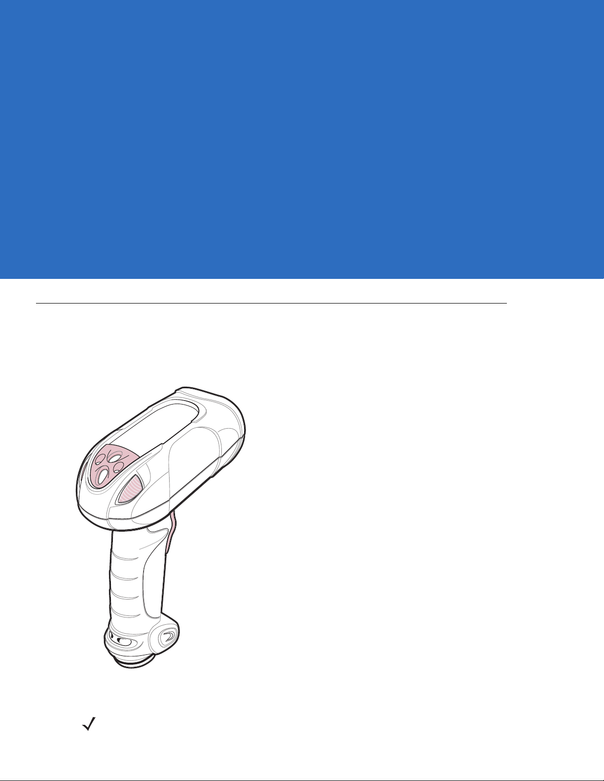
The DS3508 combines superior 1D and 2D omnidirectional bar code scann ing and sub-se cond image capture and
transfer with a light-weight, hands-free/hand-held design. The digital scanner accommodates both hands-free use
(in the scan stand) and hand-held use. Whether in hands-free (presentation) or hand-held mode, the digital
scanner ensures comfort and ease of use for extended periods of time.
Figure 1-1
NOTE Hands-free (presentation) scanning does not apply to the DS3508-ER configuration.
DS3508 Digital Scanner
Page 22

1 - 2 DS3508 Product Reference Guide
Interfaces
The DS3508 digital scanner supports:
•
USB connection to a host. The digital scanner autodetects a USB host and defaults to the HID keyboard
interface type. Select other USB interface types by scanning programming bar code menus.This interface
supports the following international keyboards (for Windows® environment): North America, Germ an,
French, French Canadian, Spanish, Italian, Swedish, UK English, Portuguese-Brazilian, and Japanese.
•
Standard RS-232 connection to a host. Scan bar code menus to set up communication of the digital scanner
with the host.
•
Connection to IBM 468X/469X hosts. Scan bar code menus to set up communication of the digital scanner
with the IBM terminal.
•
Keyboard Wedge connection to a host. The host interprets scanned data as keystrokes. Scan bar code
menus to set up communication of the digital scanner with the host. This interface supports the following
international keyboards (for Windows® environment): Nort h America, German, French, French Canadian,
French Belgian, Spanish, Italian, Swedish, UK English, Portuguese-Brazilian, and Japanese.
Unpacking
Remove the digital scanner from its packing and inspect it for damage. If the scanner was damaged in transit,
contact Zebra Support. See page xviii for contact information. KEEP THE PACKING. It is the approved shipping
container; use this to return the equipment for servicing.
Page 23
Setting Up the Digital Scanner
Installing the Interface Cable
NOTE Different hosts require different cables. The connectors illustrated in each host chapter are examples only.
Connectors vary from those illustrated, but the steps to connect the digital scanner are the same.
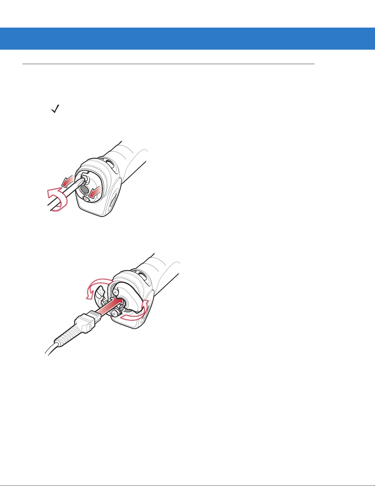
1. Loosen the two screws on the cable clamp at the bottom of the scanner and gently pull the clamp away from
the bottom of the scanner.
Getting Started 1 - 3
Figure 1-2
2. Open the clamp and plug the interface cable modular connector into the cable interface port on the bottom of
the scanner handle.
Figure 1-3
3. Gently tug the cable to ensure the connector is properly secured.
Removing the Cable Clamp
Inserting the Interface Cable
Page 24
1 - 4 DS3508 Product Reference Guide
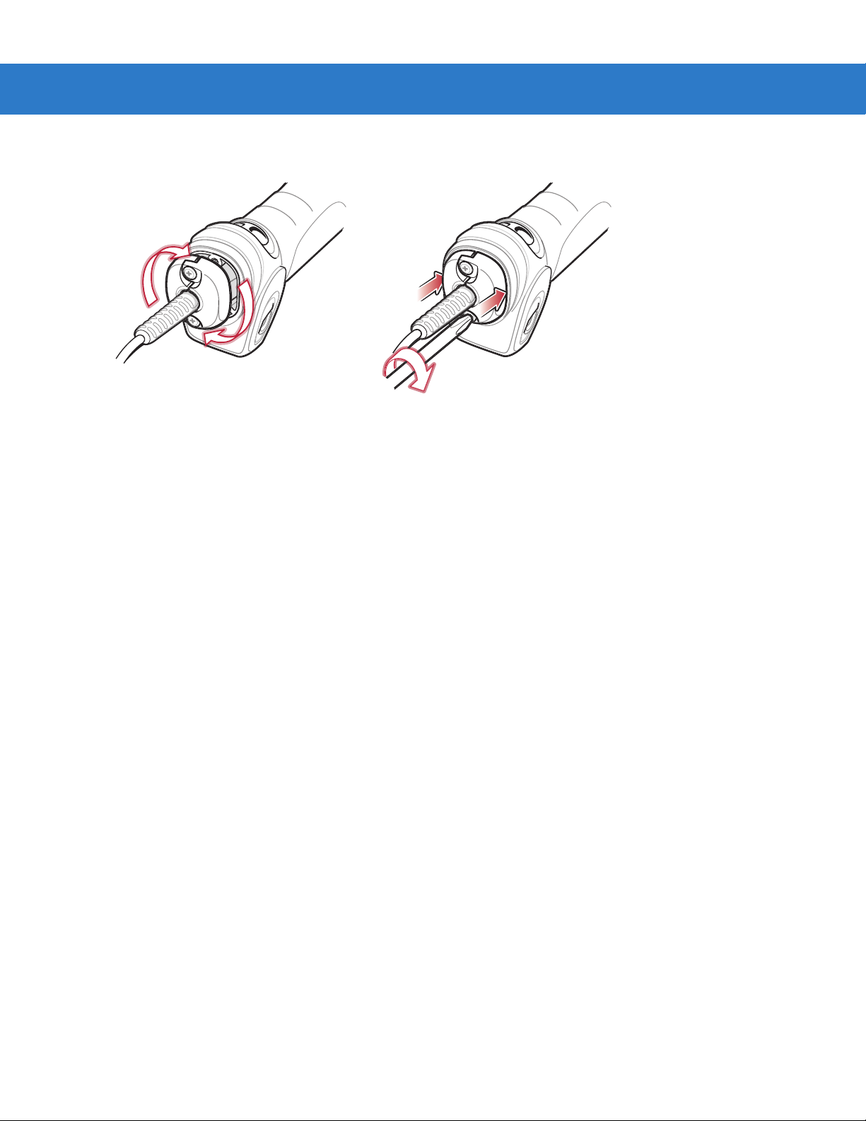
4. Close the clamp, push it back into place and tighten the screws on the clamp to secure the cable into the
bottom of the scanner.
Figure 1-4
5. Connect the other end of the interface cable to the host (see the specific host chapter for information on host
connections).
Closing the Cable Clamp
Removing the Interface Cable
1. Loosen the two screws on the cable clamp at the bottom of the scanner and gently pull the clamp away from
the bottom of the scanner.
2. Open the clamp and unplug the interface cable modular connector from the cable interface port on the bottom
of the scanner handle. Carefully slide out the cable.
3. Follow the steps for Installing the Interface Cable on page 1-3 to connect a new cabl e.
Connecting Power (if required)
If the host does not provide power to the digital scanner, connect an external power supply:
1. Connect the interface cable to the base of the digital scanner, as described in Installing the Interface Cable on
page 1-3.
2. Connect the other end of the interface cable to the host (refer to the host manual to locate the correct port).
3. Plug the power supply into the power jack on the interface cable. Plug the other end of the power supp ly into
an AC outlet.
Configuring the Digital Scanner
To configure the digital scanner use the bar codes included in this manual. See Chapter 4, User Preferences &
Miscellaneous Digital Scanner Options and Chapter 5, Imaging Preferences for infor mation about programming the
digital scanner using bar code menus. Also see each host-specific chapter to set up connection to a specific host
type.
Page 25

Accessories
Required Accessories
The digital scanner requires an interface cable and may require a power supply. These items can be purchased
from Zebra.
Optional Accessories
Contact Zebra to purchase the optional accessories inTable 1-1 for the DS3508.
Getting Started 1 - 5
Table 1-1
Scanner Belt Holster 11-35035-01R
Intellistand for DS3508 20-54090-07R (see page 2-5).
Desk Top Holder 20-67176-01R
Multi-Mount Stand 12-44267-01R
Tool Balancer 50-15400-03
Optional Accessories
Accessory Part Number
Page 26

1 - 6 DS3508 Product Reference Guide
Page 27
Chapter 2 Scanning
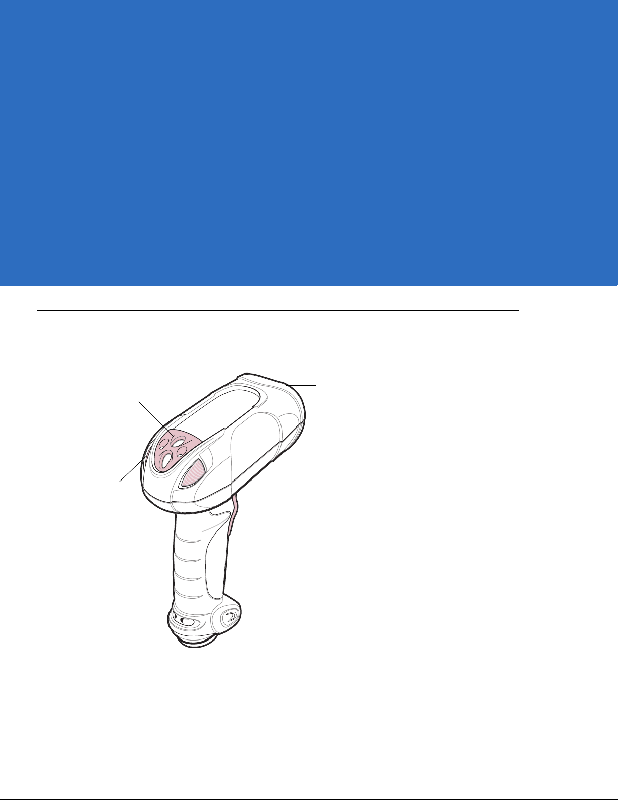
Scan Trigger
Scan Window
LED
Indicators
Tether Plate
Introduction
This chapter provides beeper and LED definitions, techniqu es involved in scanning bar codes, general instructions
and tips about scanning, and decode zone diagrams.
Figure 2-1
Parts
Page 28

2 - 2 DS3508 Product Reference Guide
Beeper Definitions
The digital scanner issues different beep sequences and patterns to indicate status. Table 2-1 defines beep
sequences that occur during both normal scanning and while programming the digital scanner.
Table 2-1
Standard Use
Low/medium/high beeps Power up.
Short high beep A bar code symbol was decoded (if decode beeper is enabled).
4 long low beeps Transmission error.
5 low beeps Conversion or format error.
Low/low/low/extra low beeps RS-232 receive error.
High beep The digital scanner detected a <BEL> character over RS-232.
Image Capture
Low beep Snapshot mode started or completed.
High/low beeps Snapshot mode timed out.
Parameter Menu Scanning
Low/high beeps Input error; incorrect bar code, progr amming sequence, or
High/low beeps Keyboard parameter selected. Enter value using numeric bar codes.
Beeper Definitions
Beeper Sequence Indication
Cancel
scanned.
High/low/high/low beeps Successful program exit with change in parameter setting.
Code 39 Buffering
High/low beeps New Code 39 data was entered into the buffer.
3 long high beeps Code 39 buffer is full.
High/low/high beeps The Code 39 buffer was erased.
Low/high/low beeps The Code 39 buffer was erased or there was an attempt to clear or transmit an
empty buffer.
Low/high beeps A successful transmission of buffered data.
Macro PDF
2 low beeps
2 long low beeps
3 long low beeps Out of memory. There is not enough buffer space to store the current MPDF
MPDF sequence buffered.
File ID error. A bar code not in the current MPDF sequence was scanned.
symbol.
Page 29

Scanning 2 - 3
Table 2-1
4 long low beeps Bad symbology. Scanned a 1D or 2D bar code in a MPDF sequence, a duplicate
5 long low beeps Flushing MPDF buffer.
Fast warble beep Aborting MPDF sequence.
Low/high beeps Flushing an already empty MPDF buffer.
Host Specific
USB only
4 short high beeps The digital scanner has not completed initialization. Wait several seconds and
Low/medium/high beeps
upon scanning a USB device
type
Low/medium/high beeps
occur more than once
Beeper Definitions (Continued)
Beeper Sequence Indication
MPDF label, a label in an incorrect order, or trying to transmit an empty or illegal
MPDF field.
scan again.
Communication with the host must be established before the digital scanner can
operate at the highest power level.
The USB host can put the digital scanner in a state where power to the scanner i s
cycled on and off more than once. This is normal and usually happens when the
PC cold boots.
RS-232 only
1 short high beep A <BEL> character is received and Beep on <BEL> is enabled.
Page 30

2 - 4 DS3508 Product Reference Guide
LED Definitions
In addition to beep sequences, the digital scanner uses a two-color LED to indicate status. Table 2-2 defines LED
colors that display during scanning.
Table 2-2
Hand-Held Scanning Standard Use
Green A bar code was successfully decoded.
Red Transmission error, conversion or format error, or RS-232 receive error.
Off No power is applied to the digital scanner, or the scanner is on and ready to scan.
Presentation (Hands-Free) Scanning Standard Use
Green The scanner is on and ready to scan.
Momentarily Off A bar code was successfully decoded.
Red Transmission error, conversion or format error, or RS-232 receive error.
Off No power is applied to the digital scanner, or the scanner is in low power mode.
Parameter Programming
Green Number expected. Enter value using numeric bar codes.
Red Input error: incorrect bar code, programming sequence, or Cancel scanned.
Standard LED Definitions
LED Indication
Successful program exit with change in parameter setting.
ADF Programming
Green Enter another digit. Add leading zeros to the front if necessary.
Enter another alphabetic character or scan the
All criteria or actions cleared for current rule, continue entering rule.
Delete last saved rule. The current rule is left intact.
All rules deleted.
Blinking Green Enter another criterion or action, or scan the
Green after Blinking Rule saved. Rule entry mode exited.
Cancel rule entry. Rule entry mode exited because of an error or the user asked to exit
rule entry.
Red Out of rule memory. Erase some existing rules, then try to save rule again.
Entry error , wrong bar code scan ned, or criteria/actio n list is too long for a rule. Re-enter
criterion or action.
End of Message
Save Rule
bar code.
bar code.
Page 31

Scanning
Scanner “Cup”
Adjust height of
IntelliStand
Adjust angle of
scanner “cup”
Scanning 2 - 5
The DS3508 has a built-in, light-weight stand to easily accommodate both
hands-free (presentation)
and hand-held
scanning.
NOTE Certain areas of the digital scanner ’s handle may feel warm at times. This is normal.
NOTE Hands-free (presentation) scanning does not apply to the DS3508-ER configuration.
Presentation Mode (DS3508-SR/HD/DP)
The optional Intellistand adds greater flexibility to scanning operation. When you place the digital scanner in the
stand’s “cup,” the scanner’s built-in sensor places the scanner in presentation (hands-free) mode. When you
remove the digital scanner from the stand it operates in its normal hand-held mode.
Figure 2-2
Scanning in Hands-Free Mode
To operate the digital scanner in the Intellistand:
1. Connect the digital scanner to the host (see the appropriate host chapter for information on host connections).
2. Insert the digital scanner in the Intellistand by placing the front of the digital scanner into the stand’s “cup” (see
Figure 2-2).
3. Use the Intellistand’s adjustment knobs to adjust the height and angle of the digital scanner.
4. Center the symbol in the aiming pattern.
Page 32

2 - 6 DS3508 Product Reference Guide
5. Upon successful decode, the digital scanner beeps and the LED turns green. For more information on beeper
and LED definitions, see Table 2-1 on page 2-2 and Table 2-2 on page 2-4.
NOTE Hands-free (presentation) scanning does not apply to the DS3508-ER configuration.
Hand-Held Scanning
Aim the digital scanner at a bar code and pull the trigger to decode.
Figure 2-3
Figure 2-4
Scanning in Hand-Held Mode: DS3508-SR/HD/DP
Scanning in Hand-Held Mode: DS3508-ER
Page 33

Scanning 2 - 7
1D bar code symbol
2D bar code symbol
2D dot peen DPM symbol
Aiming Pattern
DS3508-SR/HD/DP Aiming
When scanning, the DS3508-SR/HD/DP projects a red laser aiming pattern which allows positioning the bar code
within its field of view. See Decode Ranges on page 2-9 for the proper distance to achieve between the digital
scanner and a bar code.
Figure 2-5
DS3508-SR/HD/DP Aiming Pattern
If necessary , the digital scanner turns on its red LEDs to illuminate the target bar code.To scan a bar code, center
the symbol in any orientation within the aiming pattern. Be sure the entire symbol is within the rectangular area
formed by the cross pattern.
Figure 2-6
Scanning Orientation with Aiming Pattern
NOTE Scanning Direct Part Mark (DPM) bar codes with the DS3508-DP20005R digital scanner: Due to the
reflective nature of some surfaces used with DPM bar codes (see Figure 2-6), it may be necessary to tilt
the scanner at an angle relative to the target (Zebra recommends 25-45 degrees). Fo r example, when
scanning a 15 mil dot peen Data matrix bar code marked on an aluminum surface with the
DS3508-DP20005R, present the target between two and three inches from the nose of the scanner, and
tilt the scanner at a 30 degree angle.
When scanning standard (non-DPM) bar codes with any configuration of the DS3508 digital scanner,
follow the standard aiming instructions described in DS3508-SR/HD/DP Aiming on page 2-7.
Page 34

2 - 8 DS3508 Product Reference Guide
0123 45
0123 45
0123 45
0123 45
The digital scanner can also read a bar code presented within the aiming pattern but not centered. The top
examples in Figure 2-7 show acceptable aiming options, while the bottom examples can not be decoded.
Figure 2-7
Acceptable and Incorrect Aimi ng
Page 35

Decode Ranges
DS3508-SR/HD/DP
Scanning 2 - 9
Table 2-3
Code 39 - 3 mil
Code 39 - 4 mil
Code 39 - 5 mil
Code 39 - 7.5 mil
Code 39 - 20 mil
100% UPC - 13 mil
PDF417 - 6.67 mil
PDF417 - 10 mil
DS3508-SR/HD/DP Depth of Field
Symbol Density DS3508-SR DS3508-HD/DS3508-DP
N/A 1.10 in. - 1.60 in.
2.79 cm - 4.06 cm
2.60 in. - 4.50 in.
6.60 cm - 11.43 cm
1.00 in. - 6.30 in.
2.54 cm - 16.00 cm
Contact - 10.10 in.
Contact - 25.65 cm
1.00 in. - 20.90 in.
2.54 cm - 53.09 cm
0.90 in. - 15.10 in.
2.29 cm - 38.35 cm
2.70 in. - 6.10 in.
6.86 cm - 15.49 cm
0.40 in. - 9.30 in.
1.02 cm - 23.62 cm
Contact - 3.5 in.
Contact - 8.89 cm
Contact - 4.2 in.
Contact - 10.67 cm
Contact - 5.4 in.
Contact - 13.72 cm
1.10 in. - 9.20 in.
2.79 cm - 23.37 cm
0.80 in. - 6.20 in.
2.03 cm - 15.75 cm
Contact - 3.70 in.
Contact - 9.40
Contact - 4.50 in.
Contact - 11.43 cm
PDF417 - 15 mil
Data Matrix - 4 mil
Data Matrix - 5 mil
Data Matrix - 7.5 mil
Data Matrix - 10 mil
QR Code - 4 mil
3.30 in. - 14.80 in.
8.38 cm - 37.59 cm
N/A 1.00 in. - 2.10 in.
N/A 0.40 in. - 2.70 in.
2.10 in. - 5.50 in.
5.33 cm - 13.97 cm
1.10 in. - 7.10 in.
2.79 cm - 18.03 cm
N/A 1.10 in. - 1.40 in.
3.20 in. - 5.60 in.
8.13 cm - 14.22 cm
2.54 cm - 5.33 cm
1.02 cm - 6.86 cm
Contact - 3.50 in.
Contact - 8.89 cm
Contact - 4.40 in.
Contact - 11.18 cm
2.79 cm - 3.56 cm
Page 36

2 - 10 DS3508 Product Reference Guide
Table 2-3
Symbol Density DS3508-SR DS3508-HD/DS3508-DP
QR Code - 5 mil
QR Code - 7.5 mil
QR Code - 10 mil
DS3508-ER
Table 2-4
Code 39 - 7.5 mil
Code 39 - 10 mil
DS3508-SR/HD/DP Depth of Field (Continued)
N/A 0.50 in. - 2.20 in.
N/A Contact - 3.30 in.
1.50 in. - 6.10 in.
3.81 cm - 15.49 cm
DS3508-ER Depth of Field
Symbol Density Depth of Field
8.50 in. - 34.00 in.
21.59 cm - 86.36 cm
8.00 in. - 41.50 in.
20.32 cm - 105.41 cm
1.27 cm - 5.59 cm
Contact - 8.38 cm
Contact - 4.00 in.
Contact - 10.16 cm
Code 128 - 15 mil
Code 39 - 20 mil
Code 39 - 55 mil
Code 39 - 100 mil
Code 39 - 100 mil reflective
Data Matrix - 10 mil
Data Matrix - 55 mil
Data Matrix - 100 mil
Data Matrix - 314 mil
* Dependent on length of bar codes.
7.00 in. - 47.50 in.
17.78 cm - 120.65 cm
* - 88.00 in.
* - 223.52 cm
* - 205.00 in.
* - 520.70 cm
* - 335.00 in.
* - 850.90 cm
* - 340.00 in.
* - 863.60 cm
8.25 in. - 16.50 in.
20.96 cm - 41.91 cm
* - 89.50 in.
* - 227.33 cm
* - 168.50 in.
* - 427.99 cm
* - 450.00 in.
* - 1143.00 cm
Page 37

Chapter 3 Maintenance & Technical
Specifications
Introduction
This chapter provides suggested digital scanner maintenance, troubleshoo ting, technical specifications, and signa l
descriptions (pinouts).
Maintenance
Cleaning the scan window is the only maintenance required. A dirty window can affect scanning accuracy.
•
Do not allow abrasive material to touch the window.
•
Remove any dirt particles with a damp cloth.
•
Wipe the window using a tissue moistened with ammonia/water.
•
Do not spray water or other cleaning liquids directly into the window.
Page 38

3 - 2 DS3508 Product Reference Guide
Troubleshooting
Table 3-1
The aiming pattern does not
appear when pressing the
trigger.
Digital scanner emits short
low/short medium/short high
beep sequence (power-up beep
sequence) more than once.
Troubleshooting
Problem Possible Causes Possible Solutions
No power to the digital scanner. If the configuration requires a power
supply, re-connect the power supply.
Incorrect host interface cable is used. Connect the correct host interface
cable.
Interface/power cables are loose. Re-connect cables.
Digital scanner is disabled. For IBM 468x and USB IBM hand-held,
IBM table top, and OPOS modes,
enable the digital scanner via the host
interface. Otherwise, see the technical
person in charge of scanning.
If using RS-232 Nixdorf B mode, CTS
is not asserted.
Aiming pattern is disabled. Enable the aiming pattern. See
The USB bus may put the digital
scanner in a state where power to the
scanner is cycled on and off mor e than
once.
Assert CTS line.
Hand-Held Decode Aiming Pattern on
page 4-30
Normal during host reset.
.
Digital scanner emits aiming
pattern, but does not decode the
bar code.
Digital scanner emits 4 short
high beeps during decode
attempt.
Digital scanner is not programmed for
the correct bar code type.
Bar code symbol is unreadable. Scan test symbols of the same bar
The symbol is not completely inside
aiming pattern.
Digital scanner has not completed
USB initialization.
Program the digital scanner to read that
type of bar code. See
Symbologies
code type to determine if the bar code
is defaced.
Move the symbol completely within the
aiming pattern.
Wait several seconds and scan again.
.
Chapter 10,
Page 39

Maintenance & Technical Specifications 3 - 3
Table 3-1
Digital scanner decodes bar
code, but does not transmit the
data to the host.
Host displays scanned data
incorrectly.
Troubleshooting (Continued)
Problem Possible Causes Possible Solutions
Digital scanner is not programmed for
the correct host type.
Interface cable is loose. Re-connect the cable.
If the digital scanner emits 4 long low
beeps, a transmission error occurred.
If the digital scanner emits 5 low
beeps, a conversion or format error
occurred.
If the digital scanner emits
low/high/low beeps, it detected an
invalid ADF rule.
If the digital scanner emits high/low
beeps, the scanner is buffering Code
39 data.
Digital scanner is not programmed to
work with the host.
Scan the appropriate host type
programming bar code. See the
chapter corresponding to the host type.
Set the scanner's communication
parameters to match the host's setting.
Configure the digital scanner's
conversion parameters properly.
Program the correct ADF rules. Refer
to the Advanced Data Formatting
Programmer Guide.
Normal scanning a Code 39 bar code
and the Code 39 Buffering option is
enabled.
Scan the appropriate host type
programming bar code.
Digital scanner emits
high/high/high/low beeps when
not in use.
Digital scanner emits low/high
beeps during programming.
Digital scanner emits
low/high/low/high beeps during
programming.
For RS-232, set the digital scanner's
communication parameters to match
the host's settings.
For a Keyboard Wedge configuration,
program the system for the correct
keyboard type, and turn off the CAPS
LOCK key.
Program the proper editing options
(e.g., UPC-E to UPC-A Conversion).
RS-232 receive error. Normal during host reset. Otherwise,
set the digital scanner's RS-232 parity
to match the host setting.
Input error or
scanned.
Out of ADF parameter storage space. Erase all rules and re-program with
Cancel
bar code was
Scan the correct numeric bar codes
within range for the parameter
programmed.
shorter rules.
Page 40

3 - 4 DS3508 Product Reference Guide
Table 3-1
Troubleshooting (Continued)
Problem Possible Causes Possible Solutions
Digital scanner emits
low/high/low beeps.
Digital scanner emits a
power-up beep after changing
USB host type.
Digital scanner emits one high
beep when not in use.
NOTE If after performing these checks the digital scanner still experiences problems, contact the distributor or
call Zebra Support. See page xviii for the telephone numbers.
Clearing Code 39 buffer. Normal when scanning the Code 39
Buffering
Clear Buffer
bar code or
upon attempt to transmit an empty
Code 39 buffer.
The USB bus re-established power to
Normal when changing USB host type.
the digital scanner.
In RS-232 mode, a <BEL> character
was received and Beep on <BEL>
option is enabled.
Normal when
Beep on <BEL>
is
enabled and the digital scanner is in
RS-232 mode.
Page 41

Technical Specifications
Maintenance & Technical Specifications 3 - 5
Table 3-2
Physical Characteristi cs
Dimensions 7.34 in. H x 4.82 in. W x 2.93 in. D
Weight (without cable) 12.8 oz. (363 gm)
Voltage and Current DS3508-SR/HD/DP: 5 volts ±10%, 330mA
Performance Characteristics
Light Source Aiming pattern: 650nm visible laser diode
Imager Field of View Standard Range Focus: 39.6 H x 25.7 V
Roll/Pitch/Yaw DS3508-SR/HD/DP: ±360, ±65, ±60
Motion Tolerance DS3508-SR/HD/DP: up to 100 in/sec (2.54 m/sec) in presentation mode
Technical Specifications
Item Description
(18.65 cm H x 12.25 cm W x 7.43 cm D)
DS3508-ER: 5 volts ±10%, 1.2A
Illumination: 630nm LED
High Density Focus: 38.4 H x 24.9 V
DS3508-ER: ±360, ±60, ±65
(horizontal read rate)
DS3508-ER: up to 60 in/sec (1.52 m/sec) for 100% 13 mil UPC;
motion tolerance varies depending on code type, scan distance and print quality
Symbology Decode Capability
1D UPC/EAN (UPCA/UPCE/UPCE1/EAN-8/EAN-13/ JAN-8/JAN-13 plus
supplementals, ISBN (Bookland), ISSN, Coupon Code), Code 39 (Standard, Full
ASCII, Trioptic), Code 128 (Standard, Full ASCII, UCC/EAN-128, ISBT-128
Concatenated), Code 93, Codabar/NW7,Code 11 (Standard, Matrix 2 of 5), MSI
Plessey, I 2 of 5 (Interleaved 2 of 5 / ITF, Discrete 2 of 5, IATA, Chinese 2 of 5),
GS1 DataBar (Omnidirectional, Truncated, Stacked, Stacked Omnidirectional,
Limited, Expanded, Expanded Stacked, Inverse), Base 32 (Italian Pharmacode)
PDF417 (and variants) PDF417 (Standard, Macro), MicroPDF417 (Standard, Macro), Composite Codes
(CC-A, CC-B, CC-C)
2D TLC-39, Aztec (Standard, Inverse), MaxiCode, DataMatrix/ECC 200 (Standard,
Inverse), QR Code (Standard, Inverse, Micro)
Postal U.S. Postnet and Planet, U.K. Post, Japan Post, Australian Post, Netherlands KIX
Code, Royal Mail 4 State Customer, UPU FICS 4 State Postal, USPS 4CB
DPM Marks (DPM unit only) Datamatrix marks applied by dot-peening. All supported barcode types listed
above marked by laser etching, chemical etching, ink marking, molding, stamping
or casting methods on surfaces such as including metal, plastic, rubber or glass
Page 42

3 - 6 DS3508 Product Reference Guide
Table 3-2
Technical Specifications (Continued)
Item Description
IUID Support
Supports IUID parsing. The ability to read and separate IUID
fields per application requirements
Nominal Working Range
See
Decode Ranges on page 2-9
.
(Handheld)
Interfaces Supported
USB, RS-232, RS-485 (IBM 46xx Protocols), Keyboard Wedge,
User Environment
Operating Temperature -4° to 122° F (-20° to 50° C)
Storage Temperature -40° to 158° F (-40° to 70° C)
Humidity 5% to 95% relative humidity, non-condensing
Drop Specifications Unit functions normally after repeated 6.5 ft. (2 m) drops to concrete
Ambient Light Immunity Incandescent: 150 ft. candles (1,600 LUX)
Sunlight: 8,000 ft. candles (86,000 LUX)
Fluorescent: 150 ft. candles (1,600 LUX)
Mercury Vapor: 150 ft. candles (1,600 LUX)
Sodium Vapor: 150 ft. candles (1,600 LUX)
Immune to direct exposure to normal office and factory lighting conditions, as well
as direct exposure to sunlight
123Scan
2
Electrostatic Discharge DS3508-SR/HD/DP: Conforms to 20 kV air discharge and 8 kV contact discharge
DS3508-ER: Conforms to ±15 kV air discharge and ±8 kV contact discharge
Page 43

Digital Scanner Signal Descriptions
Cable interface port
Interface cable
modular connector
Bottom of scanner
PIN 1PIN 10
Maintenance & Technical Specifications 3 - 7
Figure 3-1
Digital Scanner Cable Pinouts
Page 44

3 - 8 DS3508 Product Reference Guide
The signal descriptions in Table 3-3 apply to the connector on the digital scanner and are for reference only.
Table 3-3
Pin IBM RS-232
1 Reserved Reserved Reserved Jump to Pin 6
2 Power Power Power Power
3 Ground Ground Ground Ground
4 IBM_A(+) TxD KeyClock Reserved
5 Reserved RxD TermData D +
6 IBM_B(-) RTS KeyData Jump to Pin 1
7 Reserved CTS TermClock D 8 Reserved Reserved Reserved Reserved
9 Reserved Reserved Reserved Reserved
10 Reserved Reserved Reserved Reserved
Digital Scanner Signal Pin-outs
Keyboard
Wedge
USB
Page 45

Chapter 4 User Preferences & Miscellaneous
*High Volume
(0)
Feature/Option
* Indicates Default
Option Value
Digital Scanner Options
Introduction
You can program the digital scanner to perform various functions, or activate different features. This chapter
describes each user preference feature and provides programming bar codes for selecting these features.
The digital scanner ships with the settings shown in Table 4-1 on page 4-2 (also see Appendix A, Standard Default
Parameters for all host device and miscellaneous defaults). If the default values suit requirements, programming is
not necessary.
To set feature values, scan a single bar code or a short bar code sequence. The settings are stored in non-volatile
memory and are preserved even when th e dig ita l scan ne r is po wer e d do wn .
NOTE Most computer monitors allow scanning the bar codes directly on the screen (when using the imaging
engine). When scanning from the screen, be sure to set the document magnification to a level where you
can see the bar code clearly, and bars and/or spaces are not merging.
If not using a USB cable, select a host type (see each host chapter for specific host information) after the power-up
beeps sound. This is only necessary upon the first power-up when connected to a new host.
To return all features to default values, scan the Set Default Parameter on page 4-5. Throughout the programmin g
bar code menus, asterisks indicate (
*)default values.
Page 46

4 - 2 DS3508 Product Reference Guide
Scanning Sequence Examples
In most cases, scanning one bar code sets the parameter va lue. For example, to set the beep er tone to high , scan
the High Frequency (beeper tone) bar code listed under Beeper Tone on page 4-12. The digital scanner issues a
fast warble beep and the LED turns green, signifying a successful parameter entry.
Other parameters, such as Serial Response Time-Out or Data Transmission Formats, require scanning several
bar codes. See these parameter descriptions for this procedure.
Errors While Scanning
Unless otherwise specified, to correct an error during a scanning sequence, just re-scan the correct para meter.
User Preferences/Miscellaneous Options Parameter Defaults
Table 4-1 lists defaults for user preferences parameters. To change the default values, scan the appropriate bar
codes in this guide. These new values replace the standard default values in memory. To recall the default
parameter values, scan the Set Default Parameter on page 4-5.
NOTE See Appendix A, Standard Default Parameters for all user preferences, hosts, symbologies, and
miscellaneous default parameters.
Table 4-1
User Preferences
Set Default Parameter N/A Set Defaults 4-5
Parameter Bar Code Scanning 236 Enable 4-6
Decode Pager Motor 613 Enable 4-7
Decode Pager Motor Duration 626 500 msec 4-7
Trigger Mode 138 Level (Standard) 4-9
Beep After Good Decode 56 Enable 4-11
Beeper Volume 140 High 4-11
Beeper Tone 145 Medium 4-12
Beeper Duration 628 Medium 4-13
User Preferences Parameter Defaults
Parameter
Parameter
Number
Default
Page
Number
Suppress Power-up Beeps 721 Do Not Suppress 4-13
Hands-Free Mode 630 Enable 4-14
Presentation Performance Mode 650 Standard 4-14
Time Delay to Presentation Idle Mode 663 1 Minute 4-16
Page 47

User Preferences & Miscellaneous Digital Scanner Options 4 - 3
Table 4-1
Time Delay to Presentation Sleep Mode 662 1 Hour 4-18
Low Power Mode 128 Disable 4-20
Time Delay to Low Power Mode 146 1 Hour 4-21
Fuzzy 1D Processing 514 Enable 4-23
Picklist Mode 402 Disabled Always 4-24
PDF Prioritization 719 Disable 4-25
PDF Prioritization Timeout 720 200 ms 4-26
DPM Scanning 521 Enable 4-27
Continuous Bar Code Read 649 Disable 4-28
Decode Session Timeout 136 9.9 Sec 4-28
Timeout Between Decodes, Same Symbol 137 0.5 Sec 4-29
Timeout Between Decodes, Different Symbols 144 0.2 Sec 4-29
Hand-Held Decode Aiming Pattern 306 Enable 4-30
User Preferences Parameter Defaults (Continued)
Parameter
Parameter
Number
Default
Page
Number
Hands-Free Decode Aiming Pattern 590 Enable
Presentation Mode Field of View 609 Full 4-32
Mobile Phone/Display Mode 716 Disable 4-33
Decoding Illumination 298 Enable 4-34
Torch Mode 747 Enable 4-35
Smart LED Mode 748 Enable 4-36
Focus Mode 422 Auto-Ranging 4-37
Multicode Mode 677 Disable 4-38
Multicode Expression 661 1 4-39
Multicode Mode Concatenation 717 Disable 4-44
Multicode Concatenation Symbology 722 Concatenate as PDF417 4-45
Miscellaneous Options
Transmit Code ID Character 45 None 4-48
Prefix Value 99, 105 7013 <CR><LF> 4-49
Suffix 1 Value
Suffix 2 Value
98, 104
100, 106
7013 <CR><LF> 4-49
for PDF 4-31
Page 48

4 - 4 DS3508 Product Reference Guide
Table 4-1
Scan Data Transmission Format 235 Data as is 4-50
FN1 Substitution Values 103, 109 Set 4-51
Transmit “No Read” Message 94 Disable 4-52
UID Parsing 740 Disable 4-53
User Preferences Parameter Defaults (Continued)
Parameter
Parameter
Number
Default
Page
Number
Page 49

User Preferences
Set Default Parameter
Y o u can reset the digital scanner to two types of defaults: factory defaults or custom def aults. Scan the appro priate
bar code below to reset the decoder to its default settings and/or set its current settings as custom defaults.
•
Set Defaults - Scan this bar code to reset all default parameters as follows.
• If you previously set custom defaults by scanning Write to Custom Defaults, scan Set Defaults to
retrieve and restore the decoder’s custom default settings.
• If you did not set custom defaults, scan Restore Defaults to restore the factory default values listed in
T able A-1.
•
Set Factory Defaults - Scan this bar code to restore the factory default values listed in Table A-1. This
deletes any custom defaults set.
•
Write to Custom Defaults - Scan this bar code to set the current de coder settings as custom defaults. On ce
set, you can recover custom default settings by scanning Restore Defaults.
User Preferences & Miscellaneous Digital Scanner Options 4 - 5
*Set Defaults
Write to Custom Defaults
Set Factory Defaults
Page 50

4 - 6 DS3508 Product Reference Guide
Parameter Bar Code Scanning
Parameter # 236
To disable the decoding of parameter bar codes, including the Set Defaults parameter bar codes, scan the
Disable Parameter Scanning bar code below. To enable decoding of parameter bar codes, scan Enable
Parameter Scanning.
*Enable Parameter Bar Code Scanning
(1)
Disable Parameter Bar Code Scanning
(0)
Page 51

User Preferences & Miscellaneous Digital Scanner Options 4 - 7
Decode Pager Motor
Parameter # 613
The scanner includes a pager motor which, when enabled, vibrates the scanner for a period of time when a
successful decode occurs.
NOTE When the pager motor is enabled and the scanner is in IntelliStand, the pager motor disables until the
scanner is removed from IntelliStand.
Scan a bar code below to enable or disable the pager motor. If enabled, scan the appropriate bar code to set the
period of time in which to vibrate the scanner (see Decode Pager Motor Duration below).
Pager Motor Disable
(0)
Decode Pager Motor Duration
Parameter # 626
150 msec
*Pager Motor Enable
(1)
200 msec
Page 52

4 - 8 DS3508 Product Reference Guide
Decode Pager Motor Duration (continued)
250 msec
300 msec
400 msec
600 msec
*500 msec
750 msec
Page 53

User Preferences & Miscellaneous Digital Scanner Options 4 - 9
Trigger Mode
Parameter # 138
Select one of the following trigger modes for the digital scanner:
•
Level (Standard) - Upon trigger pull, an aiming dot appears for a programmable duration of time. After this
time, the aiming dot changes to a standard laser scanning beam for a full decode session. The laser
scanning beam stays on until the Decode Session Timeout on page 4-28 occurs, a decode occurs, or the
trigger is released. If the trigger is released before the timeout expires, the laser shuts off and no decode
occurs.
•
Two Stage Option 1 (DS3508-ER only) - Upon trigger pull, an aiming dot appears. When the trigger is released,
the aiming dot changes to a standard laser scanning beam for a full decode session. The laser scanning
beam stays on for one-third of the curr ently configure d decode timeout. If the trigger is pulled again while in a
decode session, the scanner beam returns to an aiming dot.
•
T wo Stage Option 2 (DS3508-ER only) - Upon trigger pull, a n aiming dot appears. When the trigger is re leased,
the aiming dot turns off. Pulling the trigger twice quickly turns on the standard laser scanning beam for a full
decode session. The laser scanning beam stays on until the Decode Session Timeout occurs, a decode
occurs, or the trigger is released.
•
Presentation (Blink) (DS3508-SR/HD/DP only) - The digital scanner activates decode processing when it
detects a bar code in its field of view. After a per iod of non-use, the digital scanner enters a low power mode
in which the LEDs turn off until the digital scanner senses motion.
•
Auto Aim (DS3508-SR/HD/DP only) - The digital scanner’s aiming pattern is consistently on when in auto aim
mode. A trigger pull activates decode processing. After 2 seconds of inactivity the aiming pattern shuts off.
Page 54

4 - 10 DS3508 Product Reference Guide
Trigger Mode (continued)
* Level (Standard)
(0)
Two Stage Option 1 (DS3508-ER only)
(14)
Two Stage Option 2 (DS3508-ER only)
(15)
Auto Aim (DS3508-SR/HD/DP only)
(9)
NOTE Hands-free (presentation) scanning does not apply to the DS3508-ER configuration.
Presentation (Blink) (DS3508-SR/HD/DP only)
(7)
Page 55

User Preferences & Miscellaneous Digital Scanner Options 4 - 11
Beep After Good Decode
Parameter # 56
Scan a bar code below to select whether or not the digital scanner beeps afte r a good de code. If sele ctin g Do Not
Beep After Good Decode, the beeper still operates during parameter menu scanning and to indicate error
conditions.
*Beep After Good Decode
(Enable)
(1)
Do Not Beep After Good Decode
(Disable)
(0)
Beeper Volume
Parameter # 140
To select a beeper volume, scan the Low Volume, Medium Volume, or High Volume bar code.
Low Volume
(2)
Medium Volume
(1)
*High Volume
(0)
Page 56

4 - 12 DS3508 Product Reference Guide
Beeper Tone
Parameter # 145
To select a decode beep frequency (tone), scan one of the following bar codes.
Off
(3)
Low Tone
(2)
*Medium Tone
(1)
Medium to High Tone (2-tone)
(4)
High Tone
(0)
Page 57

User Preferences & Miscellaneous Digital Scanner Options 4 - 13
Beeper Duration
Parameter # 628
To select the duration for the beeper, scan one of the following bar codes.
Short
(0)
* Medium
(1)
Long
(2)
Suppress Power-up Beeps
Parameter # 721
Select whether or not to suppress the digital scanner’s power-up beeps.
Suppress Power-up Beeps
(1)
* Do Not Suppress Power-up Beeps
(0)
Page 58

4 - 14 DS3508 Product Reference Guide
Hands-Free Mode
Parameter # 630
In
hands-free
with a bar code. Lifting the digital scanner causes it to behave acco rding to the setting of the Trigger Mode on page
4-9.
If you select Disable Hands-Free Mode, the digital scanner behaves according to the setting of the Trigger Mode
regardless of whether it is hand-held or in the scan stand.
mode, when you place the digital scanner in the scan stand, it automatically triggers when presented
*Enable Hands-Free Mode
(1)
Disable Hands-Free Mode
(0)
NOTE Hands-free (presentation) scanning does not apply to the DS3508-ER configuration.
Presentation Performance Mode
Parameter # 650
Select Standard Presentation Mode when presenting objects to the scanner. Select Enhanced Presentation
Mode when swiping items underneath the scanner.
*Standard Presentation Mode
(2)
Enhanced Presentation Mode
(0)
NOTE Hands-free (presentation) scanning does not apply to the DS3508-ER configuration.
Page 59

User Preferences & Miscellaneous Digital Scanner Options 4 - 15
Active Mode Idle Mode Sleep Mode Low Power Mode
Time Delay to
Presentation
Idle Mode value
Time Delay to
Presentation
Sleep Mode value
Time Delay to
Low Power
Mode value
Note: Time delays are cumulative.
Digital Scanner Activity Modes
The digital scanner is capable of four modes of activity:
•
Active Mode - The digital scanner uses full illumination for active scanning.
•
Idle Mode - In presentation mode only, the digital scanner’s illumination dims after a programmable time
period. See Time Delay to Presentation Idle Mode on page 4-16. The digital scanner wakes when it is lifted or
senses motion, upon presentation of a bar code, or upon a trigger pull.
•
Sleep Mode - In presentation mode only, the digital scanner’s illumination shuts off after a programmable
time period after Idle Mode has expired. See Time Delay to Presentation Sleep Mode on page 4-18. The
digital scanner wakes when it is lifted or senses motion, upon presentation of a bar code (de pending on
ambient light conditions), or upon a trigger pull.
•
Low Power Mode - The digital scanner enters a low power consumption mode after Sleep Mode has
expired, in which the LEDs turn off in order to conserve energy and prolong the life of the scanner. See Low
Power Mode. In hand-held mode, this occurs immediately after the programmed Time Delay to Low Power
Mode. In presentation mode, this occurs after idle mode and sleep mode. The digital scanner wakes when it
is lifted, senses a trigger pull, or when the host attempts to communicate.
NOTE The digital scanner does not use Low Power Mode when connected to a USB or IBM host.
NOTE Hands-free (presentation) scanning does not apply to the DS3508-ER configuration.
Figure 4-1
Power Levels
Page 60

4 - 16 DS3508 Product Reference Guide
Time Delay to Presentation Idle Mode
Parameter # 663
In presentation mode, this parameter sets the time the digital scanner remains active before entering idle mode
with dim illumination. The digital scanner wakes upon presentation of a bar code or a trigger pull.
Disable
(0)
1 Second
(1)
10 Seconds
(10)
5 Minutes
(21)
*1 Minute
(17)
15 Minutes
(27)
Page 61

User Preferences & Miscellaneous Digital Scanner Options 4 - 17
Time Delay to Presentation Idle Mode (continued)
30 Minutes
(29)
45 Minutes
(30)
1 Hour
(33)
6 Hours
(38)
3 Hours
(35)
9 Hours
(41)
NOTE Hands-free (presentation) scanning does not apply to the DS3508-ER configuration.
Page 62

4 - 18 DS3508 Product Reference Guide
Time Delay to Presentation Sleep Mode
Parameter # 662
In presentation mode, this parameter sets the time the digital scanner r emains active before entering sleep mode
with no illumination. The digital scanner wakes when it senses motion, upon presentation of a bar code, or a trigger
pull.
NOTE Digital scanner performance is not guaranteed in dim conditions.
Disable
(0)
10 Seconds
(10)
5 Minutes
(21)
1 Second
(1)
1 Minute
(17)
NOTE Hands-free (presentation) scanning does not apply to the DS3508-ER configuration.
Page 63

User Preferences & Miscellaneous Digital Scanner Options 4 - 19
Time Delay to Presentation Sleep Mode (continued)
15 Minutes
(27)
30 Minutes
(29)
45 Minutes
(30)
3 Hours
(35)
*1 Hour
(33)
6 Hours
(38)
9 Hours
(41)
Page 64

4 - 20 DS3508 Product Reference Guide
Low Power Mode
Parameter # 128
If enabled, the digital scanner enters a low power consumption mode after Sleep Mode has expired, in which the
LEDs turn off in order to conserve energy and prolon g the life of the scanner. In hand-held mode, this occurs
immediately after the programmed Time Delay to Low Power Mode. In presentation mode, this occurs after idle
mode and sleep mode. The digital scann er wake s when it is lifte d, senses a trigger pu ll, or when the host attempts
to communicate.
If disabled, power remains on after ea ch decode attempt.
*Disable Low Power Mode
(0)
Enable Low Power Mode
(1)
Page 65

User Preferences & Miscellaneous Digital Scanner Options 4 - 21
Time Delay to Low Power Mode
Parameter # 146
NOTE This parameter only applies when Low Power Mode is enabled.
This parameter sets the time the digital scanner remains active before entering lower power mode (after the
applicable activity mode - see Digital Scanner Activity Modes on page 4-15). The digital scanner wakes upon
trigger pull or when the host attempts to communicate with the digital scanner.
1 Second
(17)
1 Minute
(33)
15 Minutes
(43)
10 Seconds
(26)
5 Minutes
(37)
Page 66

4 - 22 DS3508 Product Reference Guide
Time Delay to Low Power Mode (continued)
30 Minutes
(45)
45 Minutes
(46)
*1 Hour
(49)
6 Hours
(54)
3 Hours
(51)
9 Hours
(57)
Page 67

User Preferences & Miscellaneous Digital Scanner Options 4 - 23
Fuzzy 1D Processing
Parameter # 514
This option is enabled by default to optimize decode performance on 1D bar codes, including damaged and poor
quality symbols. Disable this only if you experience time delays w he n deco din g 2D bar codes, or in detecting a no
decode.
* Enable Fuzzy 1D Processing
(1)
Disable Fuzzy 1D Processing
(0)
Page 68

4 - 24 DS3508 Product Reference Guide
Picklist Mode
Parameter # 402
Picklist mode enables the digital scanner to decode only bar codes that are aligned under the laser crosshair.
Select one of the following picklist modes for the digital scanner:
•
Disabled Always - Picklist mode is always disabled.
•
Enabled in Hand-Held Mode - Picklist mode is enabled when the digital scanner is out of hands-free mode
and disabled when the digital scanner is in presentation mode.
•
Enabled in Hands-Free Mode - Picklist mode is enabled when the digital scanner is in hands-free mode
only .
•
Enabled Always - Picklist mode is always enabled.
NOTE If you enabled DPM Scanning on page 4-27, disable Picklist Mode when scanning a DPM bar code.
Picklist performance is not guaranteed for DPM bar codes.
*Disabled Always
(0)
Enabled in Hands-Free Mode
(3)
Enabled in Hand-Held Mode
(1)
Enabled Always
(2)
NOTE Picklist Mode temporarily overrides the Disable Decode Aiming Pattern option. The Decode Aiming
Pattern cannot be disabled when the following options are selected:
• Smart LED Mode is set to Enable (DS3508-ER configuration)
• Focus Mode is set to Auto-Ranging (DS3508-ER configuration)
• Picklist Mode is set to Enable (DS3508-ER and DS3508-SR config urations)
Page 69

User Preferences & Miscellaneous Digital Scanner Options 4 - 25
PDF Prioritization
Parameter # 719
Enable this feature to delay decoding a 1D bar code (Code 128) by the value specified in PDF Prioritization
Timeout. During that time the digital scanner attempts to decode a PDF417 symbol (e.g., on a US driver's license ),
and if successful, reports this only. If it does not decode (can not find) a PDF417 symbol, it reports the 1D symbol
after the timeout. The 1D symbol must be in the device’s field of view for the digital scanner to report it. This
parameter does not affect decoding other symb olo gie s.
NOTE The 1D Code 128 bar code lengths include the following:
- 7 to 10 characters
- 14 to 17 characters
- 27 to 28 characters
In addition, a Code 39 bar code with the following lengths are considered to potentially be part of a US
driver’s license:
- 8 characters
- 12 characters.
* Disable PDF Prioritization
(0)
Enable PDF Prioritization
(1)
Page 70

4 - 26 DS3508 Product Reference Guide
PDF Prioritization Timeout
Parameter # 720
When PDF Prioritization is enabled, this timeout specifies how long the digital scanner attempts to decode a
PDF417 symbol before reporting the 1D bar code in the field of view. Scan the following bar code, then scan four
digits from Numeric Bar Codes on page D-1 that specify the timeout in milliseconds. For example, to enter 400 ms,
scan the following bar code, then scan 0400. The range is 0 to 5000 ms, and the default is 200 ms.
PDF Prioritization Timeout
Page 71

User Preferences & Miscellaneous Digital Scanner Options 4 - 27
DPM Scanning
Parameter # 521
Unlike bar codes that are typically printed on labels, a direct part mark ( DPM) is a symbol that is marked directly on
an item’s surface for permanent identification. These symbols are marked using methods such as laser etching
and dot peening (see Figure 2-6 on page 2-7 for an example of a dot peen symbol). The DS3508-DP ( DPM) reader
scans these types of symbols.
NOTE When the DS3508-DP digital scanner is DPM enabled, the digital scanner reads all symbols including
DPM, 1D, PDF417, etc. If you do not require DPM reading, scan Disable DPM Scanning to ensure
optimum scanner performance.
If you enable DPM Scanning, disable Picklist Mode on page 4-24 when scanning a DPM bar code.
Picklist performance is not guaranteed for DPM bar codes.
Also, if you enable DPM Scanning, the scanner behaves as if the Data Matrix Inverse Autodetect setting
is selected. When you disable DPM Scanning, the previous (user-selected) Data Matrix Inverse setting
remains in effect. SeeData Matrix Inverse on page 10-77.
To configure the DS3508-DP digital scanner for DPM reading:
1. If you disabled DPM scanning in the DS3508-DP digital scanner, scan Enable DPM Scanning below.
2. Before scanning a DPM bar code, ensure you enabled Data Matrix Inverse on page 10-77.
*Enable DPM Scanning
(1)
Disable DPM Scanning
(0)
Page 72

4 - 28 DS3508 Product Reference Guide
Continuous Bar Code Read
Parameter # 649
Enable this to report every bar code while the trigger is pressed.
NOTE Zebra strongly recommends enabling Picklist Mode on page 4-24 with this feature. Disabling Picklist
Mode can cause accidental decodes when more than one bar code is in the imaging engine's field of view.
*Disable Continuous Bar Code Read
(0)
Enable Continuous Bar Code Read
(1)
Decode Session Timeout
Parameter # 136
This parameter sets the maximum time decode pro ces sing con tinues d ur ing a sca n attempt. It is pr og rammab le in
0.1 second increments from 0.5 to 9.9 seconds. The default timeout is 9.9 seconds.
To set a Decode Session Timeout, scan the bar code below. Next, scan two numeric bar codes from Appendix D,
Numeric Bar Codes that correspond to the desired on time. Enter a leading zero for single digit numbers. For
example, to set a Decode Session Timeout of 0.5 seconds, scan the bar code below, then scan the 0 and 5 bar
codes. To correct an error or change the selection, scan Cancel on page D-2.
Decode Session Timeout
Page 73

User Preferences & Miscellaneous Digital Scanner Options 4 - 29
Timeout Between Decodes, Same Symbol
Parameter # 137
Use this option in presentation mode and Continuous Bar Code Read to prevent the beeper from continuously
beeping when a symbol is left in the digital scanner’s field of view. It is programmable in 0 .1 second increments
from 0.0 to 9.9 seconds. The default interval is 0.5 seconds.
To select the timeout between decodes for the same symbol, scan the bar code below, then scan two numeric bar
codes from Appendix D, Numeric Bar Codes that correspond to the desired interval, in 0.1 second increments.
Timeout Between Decodes, Same Symbol
Timeout Between Decodes, Different Symbols
Parameter # 144
Use this option in presentation mode and Continuous Bar Code Read to control the time the scanner is inactive
between decoding different symbols. It is programmable in 0.1 second increments from 0.1 to 9.9 seconds. The
default is 0.2 seconds.
To select the timeout between decodes for different symbols, scan the bar code below, then scan two numeric bar
codes from Appendix D, Numeric Bar Codes that correspond to the desired interval, in 0.1 second increments.
Timeout Between Decodes, Different Symbols
Page 74

4 - 30 DS3508 Product Reference Guide
Hand-Held Decode Aiming Pattern
Parameter # 306
Select Enable Hand-Held Decode Aiming Pattern to project the aiming pattern during bar code capture, Disable
Hand-Held Decode Aiming Pattern to turn the aiming pattern of f, or Enable Hand-Held Decode Aiming Pattern
on PDF to project the aiming pattern when the digital scanner detects a 2D bar code.
This parameter does not apply to Snapshot Mode. See Operational Modes on page 5-4.
NOTE With Picklist Mode on page 4-24 enabled, the decode aiming pattern flashes even when the Decode
Aiming Pattern is disabled.
*Enable Hand-Held Decode Aiming Pattern
(2)
Enable Hand-Held Decode Aiming Pattern on PDF
(3)
NOTE Picklist Mode temporarily over-rides the Disable Decode Aiming Pattern option. The Decode Aiming
Pattern cannot be disabled when the following options are selected:
• Smart LED Mode is set to Enable (DS3508-ER configuration)
• Focus Mode is set to Auto-Ranging (DS3508-ER configuration)
• Picklist Mode is set to Enable (DS3508-ER and DS3508-SR con fig urations)
Disable Hand-Held Decode Aiming Pattern
(0)
Page 75

User Preferences & Miscellaneous Digital Scanner Options 4 - 31
Hands-Free Decode Aiming Pattern
Parameter # 590
Select Enable Hands-Free Decode Aiming Pattern to project the aiming pattern during bar code capture,
Disable Hands-Free Decode Aiming Pattern to turn the aiming pattern off, or Enable Hands-Free Decode
Aiming Pattern on PDF to project the aiming pattern when the digital scanner detects a 2D bar code.
This parameter does not apply to Snapshot Mode. See Operational Modes on page 5-4.
NOTE With Picklist Mode on page 4-24 enabled, the decode aiming pattern flashes even when the Decode
Aiming Pattern is disabled.
Enable Hands-Free Decode Aiming Pattern
(1)
*Enable Hands-Free Decode Aiming Pattern on PDF
(2)
NOTE Picklist Mode temporarily overrides the Disable Decode Aiming Pattern parameter. The Decode Aiming
Pattern cannot be disabled (using the DS3508-SR and DS3508-ER configurations) when the following
parameters/settings are selected:
• Smart LED Mode is set to Enable (DS3508-ER configuration)
• Focus Mode is set to Auto-Ranging (DS3508-ER configuration)
• Picklist Mode is set to Enable (DS3508-ER and DS3508-SR config urations)
Disable Hands-Free Decode Aiming Pattern
(0)
Page 76

4 - 32 DS3508 Product Reference Guide
Presentation Mode Field of View
Parameter # 609
In presentation mode, by default the digital scanner searches the large r area of the aiming pattern (Full Field of
View
).
To search for a bar code in a smaller region around the aiming pattern’s center cross in order to speed search time,
select
Small Field of View or Medium Field of View.
Small Field of View
(0)
Medium Field of View
(1)
*Full Field of View
(2)
NOTE Hands-free (presentation) scanning does not apply to the DS3508-ER configuration.
Page 77

User Preferences & Miscellaneous Digital Scanner Options 4 - 33
Mobile Phone/Display Mode
Parameter # 716
This mode improves bar code reading performance off mobile phones and electronic displays. Enable this in
hand-held, hands-free, or both modes, or disable mode.
NOTE If you enable this mode, for best performance also select Presentation Performance Mode on page 4-14
and enable Hands-Free Decode Aiming Pattern on page 4-31.
*Disable Mobile Phone/Display Mode
(0)
Enable in Hand-Held Mode
(1)
Enable in Hands-Free Mode
(2)
Enable in Both Modes
(3)
NOTE Torch Mode does not function when Mobile Phone/Display Mode is enabled.
Page 78

4 - 34 DS3508 Product Reference Guide
Decoding Illumination (Hand-Held Mode only)
Parameter # 298
When in hand-held mode, selecting Enable Decoding Illumination causes the digital scanner to flash illumination
to aid decoding. Select Disable Decoding Illumination to prevent the digital scanner from using decoding
illumination.
Enabling illumination usually results in superior images. The effectiveness of the illumination decreases as the
distance to the target increases.
*Enable Decoding Illumination
(1)
Disable Decoding Illumination
(0)
Page 79

User Preferences & Miscellaneous Digital Scanner Options 4 - 35
Torch Mode (DS3508-ER Only)
Parameter # 747
When using the DS3508-ER, selecting Enable Torch Mode causes the digital scanner to provide illumination
longer to optimize decode accuracy when scanning at an extended decode range (far distance of 5 feet or greater).
Select Disable Torch Mode to prevent the digital scanner from using Torch Mode.
Disable Torch Mode
(1)
*Enable Torch Mode
(0)
NOTE Torch Mode does not function when Mobile Phone/Display Mode is enabled.
Page 80

4 - 36 DS3508 Product Reference Guide
Smart LED Mode (DS3508-ER Only)
Parameter # 748
Selecting Enable Smart LED Mode optimizes decode accuracy when scan ning near using the DS350 8-ER digital
scanner.
Select Disable Smart LED Mode to prevent the digital scanner from using Smart LED Mode.
Disable Smart LED Mode
(1)
*Enable Smart LED Mode
(0)
NOTE When using Smart LED Mode, it is normal for the illumination to appear off center.
Page 81

User Preferences & Miscellaneous Digital Scanner Options 4 - 37
Focus Mode
Parameter # 422
Select the Focus Mode to control the working range of the DS3508-ER digital scanner.
•
Select Far focus to optimize the di gital scanner to read at its far position. Use this mode when scanning lar ge
bar codes in order to fit these bar codes in the digital scanner’s field of view.
•
Select Near focus to optimize the digital scanner to read at its near position. Use this mode when scanning
small, high-density bar codes.
•
Select Alternating focus to toggle between near and far focus position.
•
Select Auto-Ranging focus to allow the digital scanner to control the focus o peration.
Far
(0)
Alternating
(2)
Near
(1)
*Auto-Ranging
(3)
NOTE When in Far Focus Mode, you may not be able to decode standard size parameter bar codes.
Page 82

4 - 38 DS3508 Product Reference Guide
Multicode Mode (DS3508-SR / DS3508-HD)
Parameter # 677
Enable this parameter to allow multiple bar codes to decode upon one trigger event based on the programmed
multicode expression. The digital scanner reports a successful decode and provides user indication only if it
decodes all bar codes indicated by the multicode expressi on, otherwise the decode fails. Bar codes a re transmitted
in the order defined in the multicode expression. Disable this to operate in normal decode mode.
NOTES The DS3508-DP and DS3508-ER configurations do not support Multicode Mode.
Enabling Multicode Mode disables Picklist Mode.
Multicode does not operate in presentation mode.
Do not use Multicode Mode if a trigger is set to Laser Preferred Decoding.
Do not use Multicode Mode if Continuous Bar Code Read is enabled.
When using this mode, always orient the digital scanner at the same distance and angle (perpendicular).
*Disable Multicode Mode
(0)
Enable Multicode Mode
(1)
Page 83

User Preferences & Miscellaneous Digital Scanner Options 4 - 39
Multicode Expression (DS3508-SR / DS3508-HD)
Parameter # 661
Use this feature to program a multicode expression for Multico de Mode (DS3508- SR / DS3508-HD) (grid meth od).
The default is 1, which indicates any bar code.
NOTE The DS3508-DP and DS3508-ER configurations do not support this feature.
To set the multicode expression:
1. Scan the bar code below.
2. Scan bar codes from the alphanumeric keyboard in the Advanced Data Formatting Programmer Guide to
define the expression.
3. Scan the End of Message bar code from the Advanced Data Formatting Programmer Guide.
Multicode Expression
Multicode Expression Syntax
Multicode Expression Syntax: [n] [Element 1]; [Element 2 ]; ... [Element n];
Where n is the number of elements in the overall expression.
The multicode expression describes the bar code(s) that the digital sca nner can expect to find in an image. Each
element represents one bar code in the digital scanner's field of view. The order of elements in the expression is
the order in which bar code data from each elemen t tran smits to the host. Ele ments are defined using one or more
of the following methods:
By Region. This type of element limits decoding to a specific area within the digital scanner's field of view. Region
coordinates are defined as the top left and bottom right corners of the region, expressed in percentages of the field
of view. These can range from 0% to 100%, or 0x00 to 0x64 in hex, for both horizontal and vertical axes. A region
element is constructed as:
[R] [4] [Top, Left] [Bottom, Right]
Where:
•
[R] is the character R
•
[4] is 0x04, indicating there are four bytes therea fte r to desc rib e th e re gio n
•
[Top, Left] are two values representing the top left corner of the region
•
[Bottom, Right] are two values representing the bottom right corner of the region
Page 84

4 - 40 DS3508 Product Reference Guide
By Code Type. An element can specify a specific bar code symbolo gy to find an d decod e somewhere in the field of
view. A code type element is constructed as:
[C] [2] [Code Type]
Where:
•
[C] is the character C
•
[2] is 0x02, indicating there are two bytes thereafter to describe the code type
•
[Code Type] is the desired symbology's parameter number (see Chapter 10, Symbologies). For single-byte
parameter numbers, extend the value to two bytes by adding 00 before the parameter number.
Notes
When defining multicode expressions consider the following:
•
Use the Code Type specifier if there are bar codes of more than one code type in view.
•
Always use the Region specifier when there are multiple bar codes of the same code type.
•
When transmission order is important (the first element in the expression transmits first), use either type to
define the order.
•
When there are unwanted bar codes in view, filter them out in one of two ways:
• Use Code Type to specify only the target bar codes.
• Use Region to identify only the target bar cod es.
•
If the expression does not contain a Region specifie r, scanning angle and distance do not matter. If you
specify a region you must scan in a fixed orientation and at a fixed distance. Because of this, it is preferable
to use the Code Type specifier rather than the Region specifier.
•
When defining regions:
• Defining a region much larger than the bar code improves tolerance to scan distance and angle, but can
cause a decode of a nearby bar code instead of the target bar code. Therefore, for best performance
define larger regions when only a few bar codes are in view and those in view are widely separated.
• Defining a region close to (or smaller than) the target bar code improves the probability of decoding this
bar code rather than one nearby, but scan distance and angle must be more accurate. Therefore, for best
performance define small regions when many bar codes are in view or those in view are close together.
•
Use Region elements to improve decode speeds by reducing the image area to search for the target bar
code.
•
Specifying Code Type may also improve decode speeds for some code types.
•
Although you can scan parameter bar codes when multicode mode is enabled, be aware of the following: If
the multicode expression defined a region(s), to scan a parameter bar code you must position the bar code
within the first region defined in the expression. In some cases, this first region is not the center of the image
and aiming at the parameter bar code does not result in a successful decode.
The following examples show the multicode expr es sion s in both hex and decimal formats, however in the sample
figures the values are decimal. Be sure to use the corr e ct base nu mbe ring system wh en creating an expressio n. A
region specified as 0x00 0x00 0x64 0x32 represents a region with coordinates of Top-Left (0,0) and Bottom Right
(100,50).
Page 85

User Preferences & Miscellaneous Digital Scanner Options 4 - 41
0
1234
5
67890
5
50%
0%
100%
0%
50%
100%
PDF417 Code
Code 128 Code
UPC-A Code
Example 1
To decode one Code 128 bar code anywhere in the image (even when bar codes of other types are in view), as in
Figure 4-3, program the expression as follows:
The expression in decimal is (formatted for readability):
1 C 2 0 8 ;
To program the expression via scanning parameters the sequence is (spaces are for readability):
[MultiCode-Expression] 01 C 02 00 08 ; [End Of Message]
To program the expression via host command (SSI/SNAPI) the sequence is:
0x01 0x43 0x02 0x00 0x08 0x3b
Figure 4-2
Multicode Expression Example 1
Page 86

4 - 42 DS3508 Product Reference Guide
PDF417 Code
(0,0)
Code 128 Code
(0,50)
(160,100)
(100,50)
50%
0%
100%
0%
50%
100%
Example 2a
To decode a Code128 (Code Type=8) on the top half of the image and a PDF417 (Code Type=15) on the bottom
half of the image, as in Figure 4-4, program the expression as follows:
The expression in decimal is (formatted for readability):
2 C 2 0 8 R 4 0 0 100 50 ; C 2 0 15 R 4 0 50 100 100 ;
To program the expression via scanning parameters the sequence is:
[MultiCode-Expression] 02 C 02 00 08 R 04 00 00 64 32 ; C 02 00 0F R 04 00 32 64 64 ; [End Of Message]
To program the expression via host command (SSI/SNAPI) the sequence is:
0x02 0x43 0x02 0x00 0x08 0x52 0x04 0x00 0 x00 0x64 0x32 0x3B 0x43 0x02 0x00 0x0F 0x52 0x04 0x00 0x32
0x64 0x64 0x3B
Example 2b
In Figure 4-4, if the bottom PDF417 bar code must transmit first, reverse the sequence of the two bar codes:
The expression in decimal is (formatted for readability):
2 C 2 0 15 R 4 0 50 100 100 ; C 2 0 8 R 4 0 0 100 50 ;
To program the expression via scanning parameters the sequence is:
[MultiCode-Expression] 02 C 02 00 0F R 04 00 32 64 64 ; C 02 00 08 R 04 00 00 64 32 ; [End Of Message]
To program the expression via host command (SSI/SNAPI) the sequence is:
0x02 0x43 0x02 0x00 0x0F 0x52 0x04 0x00 0x32 0x64 0x64 0x3B 0x43 0x02 0x00 0x0 8 0x52 0x04 0 x00 0x00
0x64 0x32 0x3B
Figure 4-3
Multicode Expression Example 2
Page 87

User Preferences & Miscellaneous Digital Scanner Options 4 - 43
40%
65%
40%
40%
PDF417 Code
Code 128 Code
Data Matrix Code
Code 128 Code
70%
60%
(70,0)
(100,40)
(100,100)
(0,0)
(40,40)
(65,60)
50%
0%
100%
0% 50% 100%
Example 3
To decode the set of three bar codes while excluding the center Code 128 bar code, as in Figure 4-4, the
expression is:
The expression in decimal is (formatted for readability):
3 C 2 0 15 R 4 0 0 50 50 ; C 2 [F0 24] R 4 70 0 100 40 ; C 2 0 8 R 4 65 60 100 100 ;
To program the expression via scanning parameters the sequence is:
[MultiCode-Expression] 03 C 02 00 0F R 04 00 00 32 32 ; C 02 F0 24 R 04 46 00 64 28 ;
C 02 00 08 R 04 41 3C 64 64 ; [End Of Message]
To program the expression via host command (SSI/SNAPI) the sequence is:
0x03 0x43 0x02 0x00 0x0F 0x52 0x04 0x00 0x00 0x32 0x32 0x3B 0x43 0x02 0xF0 0x24 0x52 0x04 0x46 0x00
0x64 0x28 0x3B 0x43 0x02 0x00 0x08 0x52 0x04 0x41 0x3C 0x64 0x64 0x3B
Figure 4-4
Multicode Expression Example 3
Page 88

4 - 44 DS3508 Product Reference Guide
Multicode Mode Concatenation (DS3508-SR / DS3508-HD)
Parameter # 717
Enable this parameter to transmit multiple decoded bar codes, as specified by the Multicode Expression
(DS3508-SR / DS3508-HD), as one bar code. Use the Multicode Concatenation Symbology (DS3508-SR /
DS3508-HD) parameter to specify how the concatenated bar codes transmit.
Disable this to transmit decoded bar codes separately.
NOTE When using Multicode Mode Concatenation, disable Transmit Code ID Character on page 4-48 and check
digits.
NOTE The DS3508-DP and DS3508-ER configurations do not support this feature.
Enable Multicode Mode Concatenation
(1)
*Disable Multicode Mode Concatenation
(0)
Page 89

User Preferences & Miscellaneous Digital Scanner Options 4 - 45
Multicode Concatenation Symbology (DS3508-SR / DS3508-HD)
Parameter # 722
Use this parameter to specify how to transmit the concatenated bar codes decoded as specified by the Multicode
Expression (DS3508-SR / DS3508-HD). Multicode Mode Concatenation (DS3508-SR / DS3508-HD) must be
enabled to use this option.
NOTE The DS3508-DP and DS3508-ER configurations do not support this feature.
Concatenation as Code 128
(1)
Concatenation as Data Matrix
(3)
*Concatenation as PDF417
(2)
Concatenation as Maxicode
(4)
Page 90

4 - 46 DS3508 Product Reference Guide
Multicode Troubleshooting
Troubleshooting Multicode Expression Programming
Use the following suggestions if encountering problems programming a multicode expression:
•
Ensure the expression is valid. Invalid expressions are rejected during programming. Wh en an expression is
rejected the previous expression remains intact. If after programming the expression the digital scanner can
still decode any bar code, the expression was possibly rejected.
•
When programming the multicode expression via parameter bar code, the digital scanner generates beeps. If
any of the following beeps do not sound during programming, an error occurred (see Table 2-1 on page 2-2
and Table 2-2 on page 2-4 for error indicators):
• Scanning the
• Scanning each value of the expression prod uc es a two -t one (s am e pitch ) beep .
• Scanning the
•
Check the expression for syntax errors.
•
Try programming a simple expression to ensure the syntax is correct. See Examples of Simple Multicode
Expressions.
Multicode Expression bar code produces a two-tone (same pitch) beep.
End Of Message bar code produces a four-tone (high-low-high-low) beep.
•
Review Notes on page 4-40 for additional hints.
Troubleshooting Multicode Mode Scanning and Decoding
Use the following suggestions if encountering problems using multicode mode:
•
If the digital scanner appears to decode any single bar code instead of the intended multiple bar codes,
ensure you enabled Smart LED Mode (DS3508-ER Only) on page 4-36. Programming the multicode
expression does not enable multicode mode.
•
When specifying Region, ensure:
• Coordinates are within range the 0-100 decimal (or 0x00 - 0x64 hexadecimal).
• Top, Left is above Bottom, Right. Top, Left is 0,0 (0x00, 0x00 hexadecimal), and Bottom, Right is 100,100
(0x64, 0x64 hexadecimal).
• Regions for two or more bar codes do not overlap.
•
When specifying Code Type ensure the digital scanner supports the code type. Try decoding a single bar
code without using multicode. If it does not decode try enabling the bar code type. See Chapter 10,
Symbologies.
•
Experiment with simpler expressions, then add to it until you discover the source of the error . For example try
the simplest expression (see Examples of Simple Multicode Expressions) and make sure you can scan a
single bar code. If so, extend the expression by adding a second bar code, specifying a region, or specifying
the code type. Verify that the digital scanner can decode this new expression. Cont inu e ad d ing to the
expression until it fails to decode as expected, indicating the source of the error.
•
Review Notes on page 4-40 for additional hints.
Page 91

User Preferences & Miscellaneous Digital Scanner Options 4 - 47
Examples of Simple Multicode Expressions
The simplest multicode expression is:
•
One bar code of any type, anywhere in the image.
•
To program this use: [MultiCode-Expression] 01 ; [End Of Message]
Another simple multicode expression is:
•
One Code 128 bar code, anywhere in the image.
•
To program this use: [MultiCode-Expression] 01 C 02 00 08 ; [End Of Message]
Page 92

4 - 48 DS3508 Product Reference Guide
Miscellaneous Scanner Parameters
Transmit Code ID Character
Parameter # 45
A Code ID character identifies the code type of a scanned bar code. This is useful when decoding more than one
code type. In addition to any single character prefix already selected, the Code ID character is inserted between
the prefix and the decoded symbol.
Select no Code ID character, a Symbol Code ID character, or an AIM Code ID character. For Code ID Characters,
see Symbol Code Identifiers on page B-1 and AIM Code Identifiers on page B-3.
NOTE If you enable Symbol Code ID Character or AIM Code ID Character, and enable Transmit “No Read”
Message on page 4-52, the digital scanner appends the code ID for Code 39 to the NR message.
Symbol Code ID Character
(2)
*None
(0)
AIM Code ID Character
(1)
Page 93

User Preferences & Miscellaneous Digital Scanner Options 4 - 49
Prefix/Suffix Values
Key Category Parameter # P = 99, S1 = 98, S2 = 100
Decimal Value Parameter # P = 105, S1 = 104, S2 = 106
Y o u can append a prefix and/o r one or two suff ixes to scan data for use in data editing. To set a value for a prefix or
suffix, scan a four-digit number (i.e., fou r bar codes from Appendix D, Numeric Bar Codes) tha t corresponds to that
value. See Table E-1 on page E-1 for the four-digit codes.
When using host commands to set the prefix or suffix, set the key category parameter to 1, then set the 3-digit
decimal value. See Table E-1 on page E-1 for the four-digit codes.
To correct an error or change a selection, scan Cancel on page D-2.
NOTE To use Prefix/Suffix values, first set the Scan Data Transmission Format on page 4-50.
Scan Prefix
(7)
Scan Suffix 2
(8)
Scan Suffix 1
(6)
Data Format Cancel
Page 94

4 - 50 DS3508 Product Reference Guide
Scan Data Transmission Format
Parameter # 235
To change the scan data format, scan one of the following eight bar codes corresponding to the desired format.
NOTE If using this parameter do not use ADF rules to set the prefix/suffix.
To set values for the prefix and/or suffix, see Prefix/Suffix Values on page 4-49.
*Data As Is
(0)
<DATA> <SUFFIX 2>
(2)
<PREFIX> <DATA >
(4)
<DATA> <SUFFIX 1>
(1)
<DATA> <SUFFIX 1> <SUFFIX 2>
(3)
Page 95

User Preferences & Miscellaneous Digital Scanner Options 4 - 51
Scan Data Transmission Format (continued)
<PREFIX> <DA TA> <SUFFIX 2>
(6)
<PREFIX> <DATA> <SUFFIX 1>
(5)
<PREFIX> <DATA> <SUFFIX 1> <SUFFIX 2>
(7)
FN1 Substitution Values
Key Category Parameter # 103
Decimal Value Parameter # 109
The Wedge and USB HID Keyboard hosts support a FN1 Substitution feature. Enabling this substitutes any FN1
character (0x1b) in an EAN128 bar code with a value. This value defaults to 7013 (Enter Key).
When using host commands to set the FN1 substitution value, set the key category parameter to 1, then set the
3-digit keystroke value. See the ASCII Character Set table for the current host interface for the desired value.
To select a FN1 substitution value via bar code menus:
1. Scan the bar code below.
Set FN1 Substitution Value
2. Locate the keystroke desired for FN1 Substitution in the ASCII Character Set table for the current host
interface. Enter the 4-digit ASCII Value by scanning each digit in Appendix D, Numeric Bar Codes.
To correct an error or change the selection, scan Cancel.
To enable FN1 substitution for USB HID keyboard, scan the Enable FN1 Substitution bar code on page 4-51.
Page 96

4 - 52 DS3508 Product Reference Guide
Transmit “No Read” Message
Parameter # 94
Scan a bar code below to select whether or not to transmit a No Read message. Enable this to transmit the
characters NR when a successful decode does not occur before trigger release or the
expires. See Decode Session Timeout on page 4-28. Disable this to send nothing to the host if a symbol does not
decode.
NOTE If you enable Transmit No Read, and also enable Symbol Code ID Character or AIM Code ID Character
for T ransmit Code ID Character on page 4-48, the digital scanner appends the code ID for Code 39 to the
NR message.
Enable No Read
(1)
Decode Session Timeout
*Disable No Read
(0)
Page 97

User Preferences & Miscellaneous Digital Scanner Options 4 - 53
UID Parsing
Parameter # 740
NOTE UID parsing is only supported by DP configurations of the digital scanner.
NOTE UID constructs are compliant with the US Department of Defense MIL - STD - 130N.
A UID, or Unique Identifier, is used to identify and track data (e.g., manufacturer, distribution, lifetime of products
and other information) specified by the United States Depa rtment of Defense for all imported packages containing
merchandise equal to or greater than $5,000.00. Vendors are required to provide a legible and permanent UID
marking, in the form of a data matrix bar code, with the contents.
DP configurations of the digital scanner read the data matrix bar code, verify it is a valid UID bar code and parse
the data into a UID bar code (Criterion: Parsed UID bar code type with UID fields). This output can be used at a
later date.
To enable/disable UID parsing, scan the appropriate bar code below. UID parsing is disabled by default. Scan
Enable Embedded UID Parsing to start the parsing process.
* Disable UID Parsing
Enable Embedded UID Parsing
Page 98

4 - 54 DS3508 Product Reference Guide
UID Parsing Output
When a UID successfully parses the fields shown in Table 4-2 are created. Each field is separated by a comma. If
data is missing from a field in the UID, a lone comma fills the field.
NOTE When a UID successfully parses, a parsed UID bar code type transmits to the host.
When parsing is unsuccessful but data transmits to the host anyway, the data is in the data matrix format.
Table 4-2
Output Fields
Field Description
1 Concatenated UID
2 Construct type (UID1 or UID2)
3 Enterprise ID
4 Serialized part #
5 Original part #
6Lot #
7 Current part #
8 Scanned data in ASCII mode
Example Output - Successful Parsed Data
D12345WS51-004041,UID2,12345,041,WS51-004,,,[)> rs 06 gs 17V12345 gs 1PWS51-004 gs S041 rs eot
Table 4-3
Output Fields
Field Description
1 D12345WS51-004041
2UID2
3 12345
4041
5 WS51-004
6 (no data supplied, comma filled field)
7 (no data supplied, comma filled field)
8 [)> rs 06 gs 17V12345 gs 1PWS51-004 gs S041 rs eot
Page 99

User Preferences & Miscellaneous Digital Scanner Options 4 - 55
UID Error Mode Options
•
UID Error Beep (default): Scan UID Error Beep to program the digital scanner no t to parse the data
contained in the UID when the UID is not formatted correctly. An error
tone sounds and no data transmits to the host.
•
UID Error Pass Data: Scan UID Error Pass Data to pro gram the digital scanner to transmit data
to the host even when parsing fails. The digital scanner reads the
incorrectly encoded UID, assumes the host can process the data and
transmits the unformatted contents of the bar code. No error tone sounds.
•
UID Error Beep and Pass Data: Scan UID Error Pass Data to program the digital scanner to transmit data
to the host even when parsing fails. The digital scanner reads the
incorrectly encoded UID, assumes the host can process the data and
transmits the unformatted contents of the bar code. An error tone sounds.
Scan the appropriate bar code below to program potential error conditions.
UID Error Beep
UID Error Beep and Pass Data
UID Error Pass Data
Page 100

4 - 56 DS3508 Product Reference Guide
Sample ADF Rule for UID
To transmit only the concatenated UID field of the parsed UID, scan the bar codes below, in order.
Begin New Rule
Criterion: Parsed UID
Send Data Up to Character
Save Rule
,
(Comma)
 Loading...