

Page 1
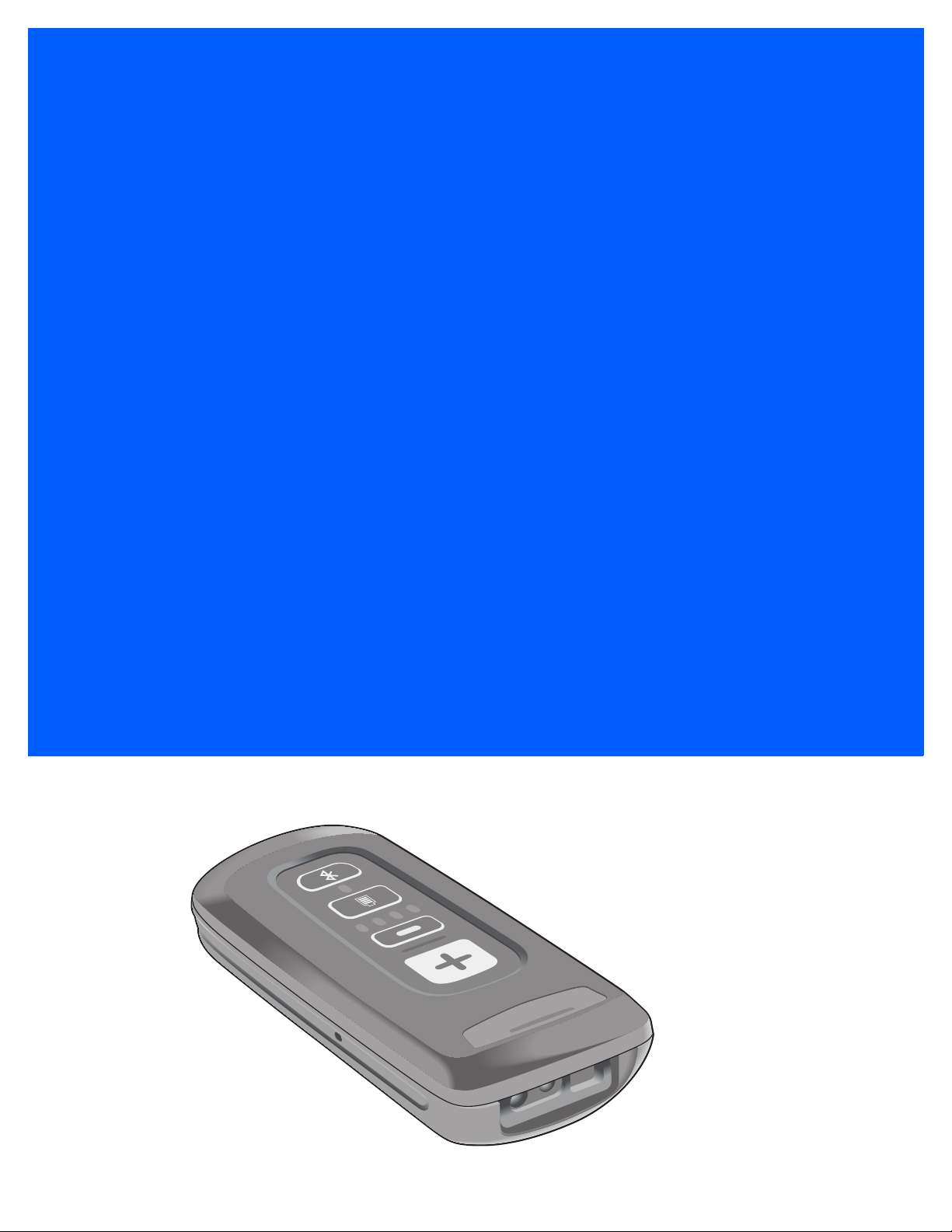
CS4070 SCANNER
PRODUCT REFERENCE
GUIDE
Page 2

Page 3

CS4070 SCANNER
PRODUCT REFERENCE GUIDE
MN000762A04
Revision A
September 2015
Page 4

ii CS4070 Scanner Product Reference Guide
No part of this publication may be reproduced or used in any form, or by any electrical or mechanical means,
without permission in writing. This includes electronic or mechanical means, such as pho to co pying, r ecordin g,
or information storage and retrieval systems. The material in this manual is subject to change without notice.
The software is provided strictly on an “as i s” basis. All sof twar e, including firmware, furnished to the user is on
a licensed basis. We grant to the user a non-transferable an d non-exclusive license to use each software or
firmware program delivered hereunder (licensed program). Except as noted below, such license may not be
assigned, sublicensed, or otherwise transferred by the user with out our prior written consent. No right to copy a
licensed program in whole or in part is granted, except as permitted under copyright law. The user shall not
modify, merge, or incorporate any form or portion of a licensed program with other program material, create a
derivative work from a licensed program, or use a licensed program in a network without written permission.
The user agrees to maintain o ur copyright noti ce on the lice nsed programs de livered hereu nder, and to include
the same on any authorized copies it makes, in whole or in part. The user agrees not to decompile,
disassemble, decode, or reverse engineer any licensed program delivered to the user or any portion thereof.
Zebra reserves the right to make changes to any product to improve reliability, function, or design.
Zebra does not assume any product liability arising out of, or in connection with, the application or use of any
product, circuit, or application described herein. No license is granted, either expressly or by implication,
estoppel, or otherwise under any patent right or patent, covering or relating to any combination, system,
apparatus, machine, material, method, or process in which Zebra products might be used. An implied license
exists only for equipment, circuits, and subsystems contained in Zebra products.
Warranty
For the complete hardware product warranty statement, go to: http://www.zebra.com/warranty.
Page 5

Revision History
Changes to the original manual are listed below:
Change Date Description
-01 Rev A 8/2014 Initial release
-02 Rev A 12/2014 Rebranded; various updates to connection and operatio n information, updated
-03 Rev A 3/2015 Updated URLs, added auto-reconnect beep description, added note to Scan
-04 Rev A 9/2015 - Added Bluetooth button press requirement and Note for unpairing
iii
default for Sleep and BTSleep, updated 123Scan2 chapter, updated index
Data Transmission Format
- Added 2 minute value to Connection Interval option
- Added Notes to Prefix and Suffix descriptions in config.ini table
- Added Unpair function to LED Indications table
- Updated Auto-reconnect default
- Added General Decoder Modes and User Preferences to User Preferences
chapter
- Added Bluetooth HID Keyboard Features section/parameters to User
Preferences chapter
- Added USB HID Keyboard Features (Dongle) chapter
- Removed Bi-directional Redundancy parameter
- Updated ADF chapter
- Removed PF Key Standard Default Table in Appendix G
Page 6

iv CS4070 Scanner Product Reference Guide
Page 7

TABLE OF CONTENTS
About This Guide
Introduction..................................................................................................................................... xiii
Configurations................................................................................................................................. xiii
Accessories..................................................................................................................................... xiii
Chapter Descriptions ...................................................................................................................... xiv
Notational Conventions................................................................................................................... xv
Related Documents ........................................................................................................................ xv
Service Information......................................................................................................................... xvi
Chapter 1: Getting Started
Introduction .................................................................................................................................... 1-1
Unpacking the Scanner .................................................................................................................. 1-2
Inserting and Removing the Battery ............................................................................................... 1-2
Inserting the Battery ................................................................................................................. 1-2
Removing the Battery .............................................................................................................. 1-3
Charging Batteries ......................................................................................................................... 1-4
Charging the Battery in a CS4070 ........................................................................................... 1-4
Charging Spare Batteries ......................................................................................................... 1-4
Charging Temperature ............................................................................................................. 1-4
Connecting to the Host Computer .................................................................................................. 1-5
Batch Connection ..................................................................................................................... 1-5
Bluetooth Connection: Development Options .......................................................................... 1-5
Pairing ...................................................................................................................................... 1-6
Unpairing .................................................................................................................................. 1-7
Deleting the CS4070 from the Device List ............................................................................... 1-7
Configuring the Scanner ................................................................................................................ 1-8
123Scan2 ................................................................................................................................. 1-8
Parameter Bar Codes and Config.ini ....................................................................................... 1-8
Updating Scanner Firmware .................................................................................................... 1-8
Editing the Configuration File ......................................................................................................... 1-9
Page 8

vi CS4070 Scanner Product Reference Guide
Chapter 2: Scanning
Introduction .................................................................................................................................... 2-1
Scanning ........................................................................................................................................ 2-1
Deleting Bar Codes .................................................................................................................. 2-2
Transmitting Bar Code Data to Host .............................................................................................. 2-2
Transferring Data from a Batch Scanner ................................................................................. 2-2
Transferring Data from a Bluetooth Scanner ........................................................................... 2-3
User Interface Definitions .............................................................................................................. 2-3
LED Indications ........................................................................................................................ 2-3
Beeper Indications ................................................................................................................... 2-5
Chapter 3: User Preferences
Introduction .................................................................................................................................... 3-1
Scanning Sequence Examples ...................................................................................................... 3-1
Errors While Scanning ................................................................................................................... 3-1
User Preferences Default Parameters ........................................................................................... 3-2
Reset Factory Defaults .................................................................................................................. 3-4
Set Date and Time ......................................................................................................................... 3-5
Set Date ................................................................................................................................... 3-5
Set Time ................................................................................................................................... 3-5
Cancel Date and Time Setting ................................................................................................. 3-5
Bluetooth Options .......................................................................................................................... 3-7
Master/Slave Set Up ................................................................................................................ 3-7
Bluetooth Unpair ...................................................................................................................... 3-8
Bluetooth Profile ....................................................................................................................... 3-8
Clear Data ................................................................................................................................ 3-9
Auto-reconnect ......................................................................................................................... 3-10
Connection Interval .................................................................................................................. 3-11
HID Security ............................................................................................................................ 3-12
Radio Output Power ................................................................................................................. 3-12
Set HID CoD to Zero ................................................................................................................ 3-13
General Decoder Modes and User Preferences ............................................................................ 3-14
Hand-Held Trigger Mode ......................................................................................................... 3-14
Hand-Held Decode Aiming Pattern .......................................................................................... 3-15
Presentation Mode Field of View ............................................................................................. 3-16
Decoding Illumination ............................................................................................................... 3-17
Illumination Brightness ............................................................................................................. 3-17
Direct Decode Indicator ........................................................................................................... 3-18
Low Light Scene Detection ...................................................................................................... 3-19
Bluetooth HID Keyboard Features ................................................................................................. 3-20
HID CAPS Lock Override ......................................................................................................... 3-20
HID Ignore Unknown Characters ............................................................................................. 3-20
Emulate Keypad ....................................................................................................................... 3-21
HID Keyboard FN1 Substitution ............................................................................................... 3-22
HID Function Key Mapping ...................................................................................................... 3-23
Simulated Caps Lock ............................................................................................................... 3-23
Convert Case ........................................................................................................................... 3-24
User Preference Settings ............................................................................................................... 3-25
Parameter Bar Code Scanning ................................................................................................ 3-25
Beep After Good Decode ......................................................................................................... 3-25
Page 9

Table of Contents vii
Beeper Volume ........................................................................................................................ 3-26
Beeper Tone ............................................................................................................................ 3-27
Mute Beeper ............................................................................................................................ 3-27
Decode Pager Motor (CS4070HC only) ................................................................................... 3-28
Decode Pager Motor Duration (CS4070HC only) .................................................................... 3-28
Picklist Mode ............................................................................................................................ 3-30
Fuzzy 1D Processing ............................................................................................................... 3-30
Mirrored Image ......................................................................................................................... 3-31
Mobile Phone/Display Mode .................................................................................................... 3-31
PDF Prioritization ..................................................................................................................... 3-32
PDF Prioritization Timeout ....................................................................................................... 3-32
Data Options .................................................................................................................. ................ 3-33
Transmit Code ID Character .................................................................................................... 3-33
Prefix/Suffix Values .................................................................................................................. 3-34
Scan Data Transmission Format ............................................................................................. 3-35
Transmit “No Read” Message .................................................................................................. 3-36
Send Versions ................................................................................................................................ 3-37
Firmware Version ..................................................................................................................... 3-37
Scan Engine Version ............................................................................................................... 3-37
Dongle Version ........................................................................................................................ 3-37
Chapter 4: USB HID Keyboard Features (Dongle)
Introduction .................................................................................................................................... 4-1
Scanning Sequence Examples ...................................................................................................... 4-1
Errors While Scanning ................................................................................................................... 4-1
USB HID Keyboard Default Parameters ........................................................................................ 4-2
USB HID Keyboard Features (Dongle) .......................................................................................... 4-3
USB Keystroke Delay .............................................................................................................. 4-3
USB CAPS Lock Override ....................................................................................................... 4-4
USB Send Bar Codes with Unknown Characters .................................................................... 4-4
Emulate Keypad ....................................................................................................................... 4-5
Emulate Keypad with Leading Zero ......................................................................................... 4-5
Quick Keypad Emulation .......................................................................................................... 4-6
USB Keyboard FN 1 Substitution ............................................................................................. 4-7
Function Key Mapping ............................................................................................................. 4-8
Simulated Caps Lock ............................................................................................................... 4-8
Convert Case ........................................................................................................................... 4-9
Chapter 5: Symbologies
Introduction .................................................................................................................................... 5-1
Scanning Sequence Examples ...................................................................................................... 5-1
Errors While Scanning ................................................................................................................... 5-2
Symbology Default Parameters ..................................................................................................... 5-2
Enable/Disable All Code Types ..................................................................................................... 5-7
UPC/EAN ....................................................................................................................................... 5-8
Enable/Disable UPC-A ............................................................................................................. 5-8
Enable/Disable UPC-E ............................................................................................................. 5-8
Enable/Disable UPC-E1 ........................................................................................................... 5-9
Enable/Disable EAN-8/JAN-8 .................................................................................................. 5-9
Page 10

viii CS4070 Scanner Product Reference Guide
Enable/Disable EAN-13/JAN-13 .............................................................................................. 5-10
Enable/Disable Bookland EAN ................................................................................................ 5-10
Bookland ISBN Format ............................................................................................................ 5-11
Decode UPC/EAN/JAN Supplementals ................................................................................... 5-12
User-Programmable Supplementals ........................................................................................ 5-15
UPC/EAN/JAN Supplemental Redundancy ............................................................................. 5-15
UPC/EAN/JAN Supplemental AIM ID Format .......................................................................... 5-16
Transmit UPC-A Check Digit ................................................................................................... 5-17
Transmit UPC-E Check Digit ................................................................................................... 5-17
Transmit UPC-E1 Check Digit ................................................................................................. 5-18
UPC-A Preamble ..................................................................................................................... 5-19
UPC-E Preamble ..................................................................................................................... 5-20
UPC-E1 Preamble ................................................................................................................... 5-21
Convert UPC-E to UPC-A ........................................................................................................ 5-22
Convert UPC-E1 to UPC-A ...................................................................................................... 5-22
EAN-8/JAN-8 Extend ............................................................................................................... 5-23
UCC Coupon Extended Code .................................................................................................. 5-23
Coupon Report ......................................................................................................................... 5-24
ISSN EAN ................................................................................................................................ 5-24
Code 128 ....................................................................................................................................... 5-25
Enable/Disable Code 128 ........................................................................................................ 5-25
Set Lengths for Code 128 ........................................................................................................ 5-25
Enable/Disable GS1-128 (formerly UCC/EAN-128) ................................................................. 5-27
Enable/Disable ISBT 128 ......................................................................................................... 5-27
ISBT Concatenation ................................................................................................................. 5-28
Check ISBT Table .................................................................................................................... 5-29
ISBT Concatenation Redundancy ............................................................................................ 5-29
Code 128 Security Level .......................................................................................................... 5-30
Code 39 ......................................................................................................................................... 5-31
Enable/Disable Code 39 .......................................................................................................... 5-31
Enable/Disable Trioptic Code 39 ............................................................................................. 5-31
Convert Code 39 to Code 32 ................................................................................................... 5-32
Code 32 Prefix ......................................................................................................................... 5-32
Set Lengths for Code 39 .......................................................................................................... 5-33
Code 39 Check Digit Verification ............................................................................................. 5-34
Transmit Code 39 Check Digit ................................................................................................. 5-34
Code 39 Full ASCII Conversion ............................................................................................... 5-35
Code 39 Security Level ............................................................................................................ 5-36
Code 93 ......................................................................................................................................... 5-37
Enable/Disable Code 93 .......................................................................................................... 5-37
Set Lengths for Code 93 .......................................................................................................... 5-37
Code 11 ......................................................................................................................................... 5-39
Code 11 ................................................................................................................................... 5-39
Set Lengths for Code 11 .......................................................................................................... 5-39
Code 11 Check Digit Verification ............................................................................................. 5-41
Transmit Code 11 Check Digits ............................................................................................... 5-42
Interleaved 2 of 5 (ITF) .................................................................................................................. 5-43
Enable/Disable Interleaved 2 of 5 ............................................................................................ 5-43
Set Lengths for Interleaved 2 of 5 ............................................................................................ 5-43
I 2 of 5 Check Digit Verification ................................................................................................ 5-45
Transmit I 2 of 5 Check Digit .................................................................................................... 5-46
Page 11

Table of Contents ix
Convert I 2 of 5 to EAN-13 ....................................................................................................... 5-46
I 2 of 5 Security Level .............................................................................................................. 5-47
Discrete 2 of 5 (DTF) ..................................................................................................................... 5-48
Enable/Disable Discrete 2 of 5 ................................................................................................. 5-48
Set Lengths for Discrete 2 of 5 ................................................................................................ 5-48
Codabar (NW - 7) ........................................................................................................................... 5-50
Enable/Disable Codabar .......................................................................................................... 5-50
Set Lengths for Codabar .......................................................................................................... 5-50
CLSI Editing ............................................................................................................................. 5-52
NOTIS Editing .......................................................................................................................... 5-52
Codabar Upper or Lower Case Start/Stop Characters Detection ............................................ 5-53
MSI ................................................................................................................................................. 5-54
Enable/Disable MSI ................................................................................................................. 5-54
Set Lengths for MSI ................................................................................................................. 5-54
MSI Check Digits ..................................................................................................................... 5-56
Transmit MSI Check Digit(s) .................................................................................................... 5-56
MSI Check Digit Algorithm ....................................................................................................... 5-57
Chinese 2 of 5 ................................................................................................................................ 5-58
Enable/Disable Chinese 2 of 5 ................................................................................................. 5-58
Matrix 2 of 5 ................................................................................................................................... 5-59
Enable/Disable Matrix 2 of 5 .................................................................................................... 5-59
Set Lengths for Matrix 2 of 5 .................................................................................................... 5-59
Matrix 2 of 5 Check Digit .......................................................................................................... 5-61
Transmit Matrix 2 of 5 Check Digit ........................................................................................... 5-61
Korean 3 of 5 ................................................................................................................................. 5-62
Enable/Disable Korean 3 of 5 .................................................................................................. 5-62
Inverse 1D ...................................................................................................................................... 5-63
GS1 DataBar .................................................................................................................................. 5-64
GS1 DataBar-14 ...................................................................................................................... 5-64
GS1 DataBar Limited ............................................................................................................... 5-64
GS1 DataBar Expanded .......................................................................................................... 5-65
Convert GS1 DataBar to UPC/EAN ......................................................................................... 5-65
GS1 DataBar Limited Security Level ....................................................................................... 5-66
Composite ...................................................................................................................................... 5-67
Composite CC-C ...................................................................................................................... 5-67
Composite CC-A/B ................................................................................................................... 5-67
Composite TLC-39 ................................................................................................................... 5-68
UPC Composite Mode ............................................................................................................. 5-68
GS1-128 Emulation Mode for UCC/EAN Composite Codes .................................................... 5-69
Postal Codes .................................................................................................................................. 5-70
US Postnet ............................................................................................................................... 5-70
US Planet ................................................................................................................................. 5-70
Transmit US Postal Check Digit ............................................................................................... 5-71
UK Postal ................................................................................................................................. 5-71
Transmit UK Postal Check Digit ............................................................................................... 5-72
Japan Postal ............................................................................................................................ 5-72
Australia Post ........................................................................................................................... 5-73
Australia Post Format .............................................................................................................. 5-74
Netherlands KIX Code ............................................................................................................ 5-75
USPS 4CB/One Code/Intelligent Mail ...................................................................................... 5-75
UPU FICS Postal ..................................................................................................................... 5-76
Page 12

x CS4070 Scanner Product Reference Guide
2D Symbologies ............................................................................................................................. 5-77
Enable/Disable PDF417 ........................................................................................................... 5-77
Enable/Disable MicroPDF417 .................................................................................................. 5-77
Code 128 Emulation ................................................................................................................ 5-78
Data Matrix ............................................................................................................................... 5-79
Data Matrix Inverse .................................................................................................................. 5-79
Decode Mirror Images (Data Matrix Only) ............................................................................... 5-80
Maxicode .................................................................................................................................. 5-81
QR Code .................................................................................................................................. 5-81
QR Inverse ............................................................................................................................... 5-82
MicroQR ................................................................................................................................... 5-82
Aztec ........................................................................................................................................ 5-83
Aztec Inverse ........................................................................................................................... 5-83
Han Xin .................................................................................................................................... 5-84
Han Xin Inverse ....................................................................................................................... 5-84
Symbology-Specific Security Levels .............................................................................................. 5-85
Redundancy Level ................................................................................................................... 5-85
Security Level .......................................................................................................................... 5-87
Intercharacter Gap Size ........................................................................................................... 5-88
Chapter 6: 123Scan2
Introduction .................................................................................................................................... 6-1
Chapter 7: Advanced Data Formatting
Introduction .................................................................................................................................... 7-1
Chapter 8: Maintenance and Technical Specifications
Introduction .................................................................................................................................... 8-1
Maintenance .................................................................................................................................. 8-1
Troubleshooting ............................................................................................................................. 8-2
Technical Specifications ................................................................................................................ 8-3
Appendix A: Standard Default Parameters
Appendix B: Accessories
Overview ........................................................................................................................................ B-1
Accessories Summary ................................................................................................................... B-2
Single-Slot CS4070 Charging Cradle with Spare Battery Charger ................................................ B-3
Battery Charging Indications .................................................................................................... B-4
Bluetooth Connectivity ............................................................................................................. B-4
Eight-Slot CS4070 Charging Cradle .............................................................................................. B-5
Battery Charging Indications .................................................................................................... B-6
Bluetooth Connectivity ............................................................................................................. B-6
Eight-Slot Spare Battery Charger .................................................................................................. B-7
Battery Charging Indications .................................................................................................... B-8
LED Indications ........................................................................................................................ B-8
Page 13

Table of Contents xi
Wall Mount Brackets ...................................................................................................................... B-9
KT-102376-01R Bracket .......................................................................................................... B-9
KT-102375-01R Bracket .......................................................................................................... B-11
Bluetooth to USB HID Dongle ........................................................................................................ B-14
Pairing to a USB HID Device ................................................................................................... B-15
Lanyard with Clip ........................................................................................................................... B-16
Attaching and Removing the Lanyard ...................................................................................... B-16
Appendix C: Bluetooth Connection Examples
Overview ........................................................................................................................................ C-1
iPad Pairing Example ..................................................................................................................... C-2
Android Pairing Example ............................................................................................................... C-3
Accessing the Android Phone Keyboard ................................................................................. C-4
Windows 7 Pairing Example .......................................................................................................... C-5
Windows 8 Pairing Example .......................................................................................................... C-7
PIN Entry Bar Codes ...................................................................................................................... C-9
Appendix D: Programming Reference
Code Type IDs ............................................................................................................................... D-1
Symbol Code Identifiers ................................................................................................................. D-4
AIM Code Identifiers ...................................................................................................................... D-6
GS1-128 (formerly UCC/EAN-128) ................................................................................................ D-11
Setting Prefixes and Suffixes ......................................................................................................... D-12
Appendix E: Sample Bar Codes
UPC-A ............................................................................................................................................ E-1
UPC-E ............................................................................................................................................ E-1
UPC-E1 .......................................................................................................................................... E-2
EAN-13 .......................................................................................................................................... E-2
EAN-8 ............................................................................................................................................ E-2
Code 39 ......................................................................................................................................... E-2
Trioptic Code 39 ............................................................................................................................. E-3
Code 93 ......................................................................................................................................... E-3
Code 11 ......................................................................................................................................... E-3
Codabar ......................................................................................................................................... E-4
MSI ................................................................................................................................................. E-4
Interleaved 2 of 5 ........................................................................................................................... E-4
GS1 DataBar-14 ............................................................................................................................ E-5
PDF417 .......................................................................................................................................... E-5
Data Matrix ..................................................................................................................................... E-5
Maxicode ........................................................................................................................................ E-5
QR Code ........................................................................................................................................ E-6
Han Xin .......................................................................................................................................... E-6
US Postnet ..................................................................................................................................... E-6
UK Postal ....................................................................................................................................... E-6
Page 14

xii CS4070 Scanner Product Reference Guide
Appendix F: Numeric Bar Codes
Numeric Bar Codes ....................................................................................................................... F-1
Cancel ............................................................................................................................................ F-3
Appendix G: ASCII Character Sets
Index
Page 15

ABOUT THIS GUIDE
Introduction
The CS4070 Scanner Product Reference Guide provides general instructions for setting up, operating,
maintaining, and troubleshooting the scanne r.
Configurations
The CS4070 scanner is available in the following configurations:
•
CS4070SR - Standard range, cordless Bluetooth
•
CS4070HC - Healthcare, cordless Bluetooth
Each scanner includes a micro USB host cable.
Accessories
See Table B-1 on page B-2 for a list of accessories.
Page 16

xiv CS4070 Scanner Product Reference Guide
Chapter Descriptions
Topics covered in this guide are as follows:
•
Chapter 1, Getting Started provides a product overview and describes how to charge, connect, and
configure the scanner.
•
Chapter 2, Scanning provides instructions for how to scan bar codes and send the data to a host, as well
as beeper and LED definitions.
•
Chapter 3, User Preferences describes each user preference feature and provides the programming bar
codes for selecting these features for the scanner. It also includes wireless communication parameters
and commonly used bar codes to customize how data is transmit te d to the host devic e.
•
Chapter 4, USB HID Keyboard Features (Dongle) describes each USB HID keyboard feature and
provides the programming bar codes for selecting these features for the scanner.
•
Chapter 5, Symbologies describes all symbology features and provides the programming bar codes for
selecting these features.
•
Chapter 6, 123Scan2 provides information on the PC-based scanner configuration tool 123Scan2.
•
Chapter 7, Advanced Data Formatting briefly describes ADF, a means of customizing data before
transmission to the host device, and includes a reference to the ADF Programmer Guide.
•
Chapter 8, Maintenance and Technical Specifications provides information on how to care for the
scanner, troubleshooting, and technical specifications.
•
Appendix A, Standard Defaul t Parameters provides a table of all host devices and miscellaneous
scanner defaults.
•
Appendix B, Accessories provides information on CS4070 accessories, which provide a variety of
product support capabilities.
•
Appendix C, Bluetooth Connection Exa mp le s provides pairing examples for several host devices.
•
Appendix D, Programming Reference provides a table of AIM code identifiers, ASCII character
conversions, and keyboard maps.
•
Appendix E, Sample Bar Codes includes sample bar codes.
•
Appendix F, Numeric Bar Codes includes numeric bar codes for parameters requiring specific numeric
values.
•
Appendix G, ASCII Character Sets includes character set tables.
Page 17
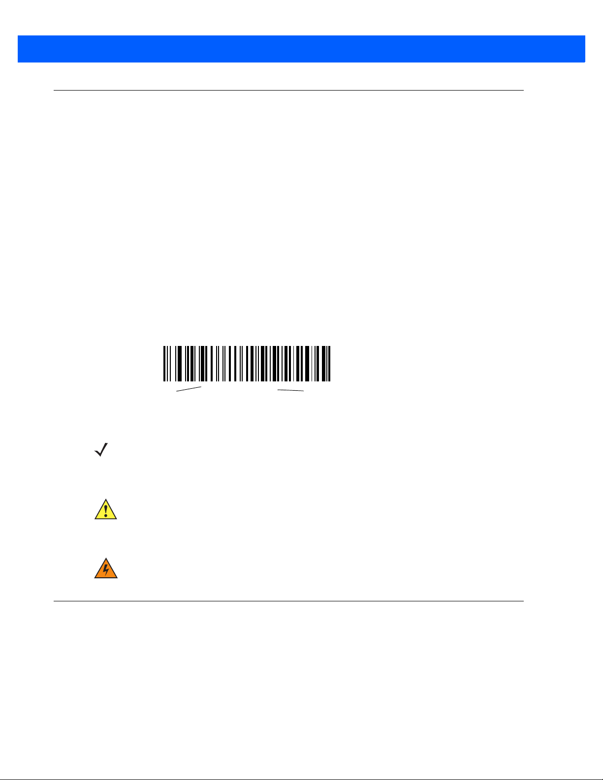
Notational Conventions
*Baud Rate 9600
Feature/Option
* Indicates Default
The following conventions are used in this document:
•
Italics are used to highlight the following:
• Chapters and sections in this and related documents
•
Bold text is used to highlight the following:
• Key names on a keypad
• Button names on a screen or window.
•
bullets (•) indicate:
• Action items
• Lists of alternatives
• Lists of required steps that are not necessarily sequential
•
Sequential lists (e.g., those that describe step-by-step procedures) appear as numbered lists.
•
Throughout the programming bar code menus, asterisks (*) are used to denote default parameter
settings.
About This Guide xv
NOTE This symbol indicates something of special interest or importance to the reader. Failure to read the note
will not result in physical harm to the reader, equipment or data.
CAUTION This symbol indicates that if this information is ignored, the possiblity of data or material damage may
WARNING! This symbol indicates that if this information is ignored the possibility that serious personal
Related Documents
•
CS4070 Scanner Quick Reference Guide (p/n MN000763A01) provides general information to help the
user get started with the scanner, including basic setup and operation instructions.
For the latest version of this guide and all guides, go to: http://www.zebra.com/support.
occur.
injury may occur.
Page 18

xvi CS4070 Scanner Product Reference Guide
Service Information
If you have a problem using the equipment, contact your facility's technical or systems support. If there is a
problem with the equipment, they will contact Global Customer Support at: http://www.zebra.com/support.
When contacting support, please have the following information available:
•
Serial number of the unit
•
Model number or product name
•
Software type and version number
Zebra responds to calls by e-mail, telephone or fax within the time limits set forth in service agreements.
If your problem cannot be solved by support, you may need to return your equipment for servicing and will be
given specific directions. Zebra is not responsible for any damages incurred during shipment if the approved
shipping container is not used. Shipping the units improperly can possibly void the warranty.
If you purchased your business product from a Zebra business partner, please contact that business partner
for support.
Page 19
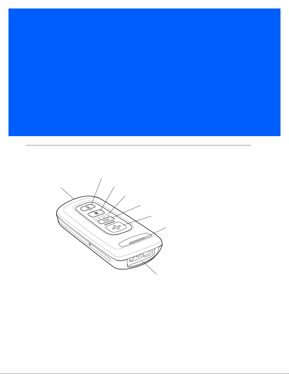
CHAPTER 1 GETTING STARTED
Scanner Window
Scan/Add Key
LED
Bluetooth Key / LED
Delete Key
Battery Level LEDs
Battery Level Key
Micro USB Port
Introduction
The CS4070 Scanner captures and stores bar codes for a variety of uses, and transmits bar code data to a
host via USB connection or Bluetooth.
Figure 1-1
This scanner supports the following host interfaces:
•
•
CS4070 Scanner
USB - The scanner connects to a USB host as a removable storage device, via a cradle or USB cable.
Bluetooth - The scanner supports Bluetooth HID connection to a host (the default) where the scanner
emulates a keyboard, as well as Serial Port Profile (SPP) connection where the scanner behaves as if
there is a serial connection.
Page 20
1 - 2 CS4070 Scanner Product Reference Guide
Battery
Release Latch
Unpacking the Scanner
Carefully remove all protective material from the scanner and save the shipping con taine r for later storag e and
shipping. Verify that you received the following equipment:
•
CS4070
•
Lithium-ion battery
•
Micro USB cable
•
Quick Start Guide.
Inspect the equipment. If any equipment is missing or damaged, contact support. See page xvi for contact
information.
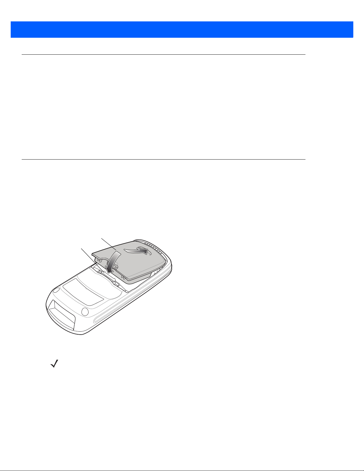
Inserting and Removing the Battery
Inserting the Battery
Before using the scanner, insert the lithium-ion battery provided with the device.
1. Insert the battery, bottom first, into the battery compartment in the back of the device.
2. Press the battery down into the battery compartment until the battery release latch snaps into place.
Figure 1-2
Inserting the Battery
NOTE Position the battery correctly, with the battery charging contacts pointing towards the bottom of the
scanner.
Page 21

Getting Started 1 - 3
Removing the Battery
To remove the battery, pull the release latch upward with one finger, and use a finger from your other hand to
pull back on the indent in the bottom of the battery housing . The battery rot ates about the bo ttom edge an d the
latch end of the battery pops up, enabling you to lift it out from the sides.
Figure 1-3
Lift Release Latch
Page 22

1 - 4 CS4070 Scanner Product Reference Guide
Charging Batteries
Before using the CS4070 for the first time, charge the battery using the micro USB cable or a cradle until the
green charge status LED lights. See Table 2-1 on p age 2-3 for charge status indications. For information about
the charging accessories available for the devic e, see Appendix B, Accessories.
NOTE If the battery is removed or replaced, the device cold boots. The internal back up battery retains the
real-time clock.
Charging the Battery in a CS4070
Use one of the following methods to charge the battery when installed in a CS4070:
•
Connect the micro USB cable to the micro USB port on the device , and the othe r end to a USB port on a
host computer. Note that the scanner can not scan when connected to a host computer.
•
Connect the micro USB cable to the micro USB port on the device, and the other end to a USB power
adapter plugged into an AC outlet.
•
Insert the CS4070 into a powered single-slot or 8-slot charging cradle. See Single-Slot CS4070 Charging
Cradle with Spare Battery Charger on page B-3 or Eight-Slot CS4070 Charging Cradle on page B-5 for
more information.
The CS4070 begins charging. The charge status LED flashes amb er while charging, then turns solid green
when fully charged. See Table 2-1 on page 2-3 for charging indications.
Charging Spare Batteries
To charge a spare battery, insert the ba tter y in to a sl o t of a powere d sp ar e battery ch arging accessory with the
charging contacts facing down, contacting the charging pins in the cradle. See Single-Slot CS4070 Charging
Cradle with Spare Battery Charger on page B-3 or Eight-Slot Spare Battery Charger on page B-7.
The battery begins charging. The charge LED on the cradle lights to show the charge status.
Charging Temperature
IMPORTANT:
Charge batteries in temperatures from 0°C to 35°C (32°F to 95°F).
Note that at temperatures above 30°C the charging temperatur e is monitored and controlled by the de vice and
the charging accessory. Charging is halted at temperatures above 35°C.
The device or accessory indicates when charging is disabled due to abnormal temper atures via it s LED and/or
battery icon. See Table 2-1 on page 2-3, Table B-2 on page B-4, and Table B-3 on page B-8.
Page 23
Connecting to the Host Computer
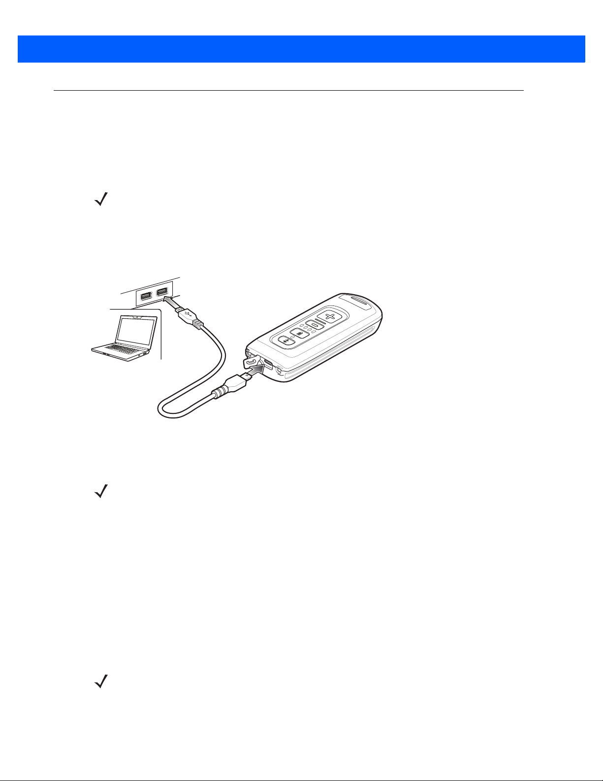
Batch Connection
The micro USB cable enables communication between the CS4070 and a PC, and charges the battery in the
CS4070.
NOTE To enter batch scanning mode, the scanner cannot be paired to a Bluetooth host.
To connect the CS4070 to a USB device:
1. Connect the USB A end of the USB cable to a USB port of the host or device.
2. Connect the micro USB connector of the cable to the CS4070.
Getting Started 1 - 5
Figure 1-4
Micro USB Cable Communication
Bluetooth Connection: Development Options
NOTE Multiple scanners can connect to a single host via SPP or HID. The host application must sort the data it
receives from the scanner.
Serial Port Profile
This Bluetooth profile emulates a serial cable to provide a simply implemented wireless replacement for
existing RS-232 based serial communications applications, including familiar control signals. It is the preferred
communication profile implementation because accidental key strokes from the keyboard or touch screen on
the host are not entered into the bar code data strea m.
Human Interface Device Emulation
This Bluetooth profile is a lightweight wrapper of the Human Interface Device protocol defined for USB. Data
transmitted from the Bluetooth scanner appears as keyboard entries to the Bluetooth host (Smartphone, PC,
etc).
NOTE Wedge data appears within whichever application has input focus.
Page 24

1 - 6 CS4070 Scanner Product Reference Guide
Pairing
Pairing the CS4070 with a host device typically requires holding the Bluetooth button to place the scanner in
discoverable mode, then scanning a pairing PIN if required. The CS4070 reme mbe rs the PIN fo r the last eigh t
devices to which it paired, and can establish connection to these devices without customer input after the initial
pairing.
NOTE When using the dongle, simply scan the pairing bar code on the dongle to connect. No PIN is required.
Note that the dongle allows a single connection only.
Supported Devices
The CS4070 supports connection to the following types of devices:
•
iOS
•
Android
•
Windows 8 Pro
•
Windows 7 Pro
•
Windows XP (Microsoft, Broadcom, and other commonly av ailab l e Blue to ot h stacks)
•
Windows RT
•
Windows Embedded Compact (CE7)
To pair to a Bluetooth-enabled host:
1. Press the scan button (+) to wake the scanner.
2. Press and hold the Bluetooth button until the scanner beeps and the blue LED begins to flash to indicate
that the scanner is discoverable by the host.
3. On the host, launch the Bluetooth pairing application and pla ce th e ap plic at ion into disco ve r Blue to ot h
device mode.
4. Select the CS4070 from the discovered device list. The Bluetooth application may prompt you to scan a
PIN it generated, or for you to create and then scan the PIN.
5. If required, scan PIN Entry Bar Codes on page C-9 that correspond to the PIN, then scan Enter.
The Bluetooth button blinks slowly to indicate that the scanner paired with the host.
NOTE Bluetooth pairing suspends temporarily while charging via a USB cable. Disconnecting the cable
re-establishes Bluetooth pairing.
NOTE When pairing with an iPad, press the delete key (- ) on the CS4070 to toggle the virtual keyboard on and
off.
For pairing examples, see Appendix C, Bluetooth Connection Examples.
Page 25
Getting Started 1 - 7
Unpairing
To temporarily unpair the scanner and host, press and hold the Bluetooth button for 2 seconds, then release.
This disables Bluetooth and the Bluetooth button stops blinking. Pressing the Bluetooth button again re-pairs
the scanner with the host.
NOTE If the Bluetooth button is held for longer than 5 seconds, the scanner terminates the wireless connection,
if already paired and connected to a host system. The scanner then enters discovery mode, searching for
a new host with which to pair and establish a new wireless connection.
To permanently unpair the scanner and host, scan Unpair on page 3-8. This allows the scanner to pair to a
different host device.
NOTE To enter batch scanning mode, the scanner cannot be paired to a Bluetooth host (applies to CS4070
model only).
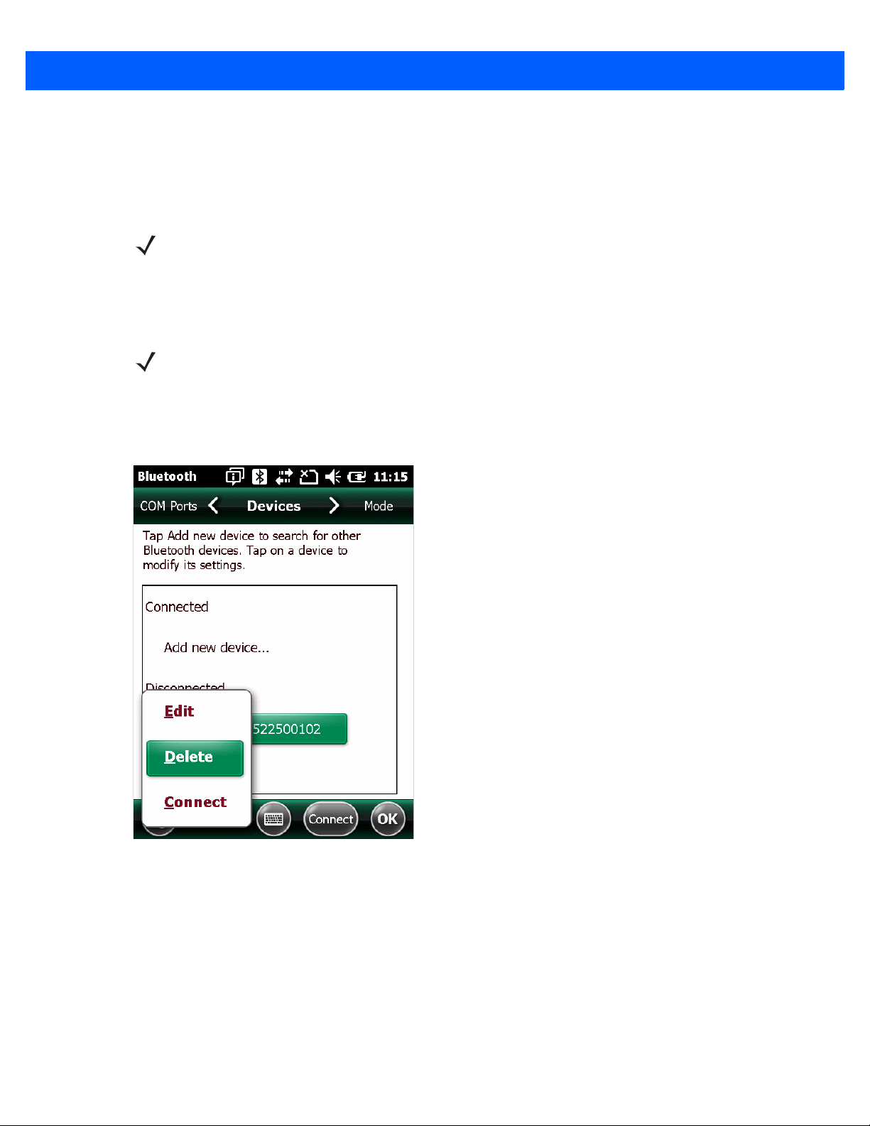
Deleting the CS4070 from the Device List
To delete the device from the discovered devices list, tap and old the device and select Delete.
Figure 1-5
Deleting Device
Page 26

1 - 8 CS4070 Scanner Product Reference Guide
Configuring the Scanner
123Scan2
To configure the scanner via 123Scan2, use this utility to generate a 2D bar code with the desired configuration
options. Scan the bar code to configure the scanner with these options. Note that the CS4070 does not support
1D configuration bar codes. See Chapter 6, 123Scan2.
Parameter Bar Codes and Config.ini
To configure the scanne r:
1. Scan the parameter bar codes in Chapter 3, User Preferences and Chapter 5, Symbologies to customize
scanner operation.
2. For additional customization, edit the Config.ini file on the scanner using the options in Editing the
Configuration File on page 1-9.
3. When deploying the new configuration to multiple scanners, to ensure unique CS4070 serial numbers
appear in the host’s discovery window, edit the
blank (“BTName=”) to ensure that each scanner uses the default BT name of
Config.ini file to either remove the BTName entry or set it to
CS4070:<serial number>.
Staging Multiple Scanners
After creating a config.ini file for one “golden” scanner with all desired settings, create a copy of the file from
this scanner and copy it to other scanners via USB connection. Set the time and date on the “cloned” scanners
by scanning bar codes from Set Date and Time on page 3-5.
NOTE When deploying the new configuration to multiple scanners, to ensure unique CS4070 serial nu mbers
appear in the host’s discovery window, edit the Config.ini file to either remove the BTName entry or set it
to blank (“BTName=”) to ensure that each scanner uses the default BT name of CS4070:<serial number>.
Updating Scanner Firmware
To update scanner firmware:
1. Connect the micro USB cable from the host to the CS4070.
2. Copy the .dat and .bin files to the root directory of the scanner.
3. Disconnect the cable when the host indicates that it is safe to remove.
After several minutes the LED turns green to indicate that the firmware was successfully installed.
Page 27

Editing the Configuration File
Use a text editor such as Notepad to set configuration values in the Config.ini editable text file in the
\Parameters folder on the CS4070. Table 1-1 lists the programmable contents of the file.
NOTE If you make errors while editing the Config.ini file, the file LOG.TXT is created in the \Parameters folder.
Consult this log file to determine the errors and make corrections.
Getting Started 1 - 9
Table 1-1
Config.ini File Content
Name Description Values Default
AutoReconnect Enable or disable automatic Bluetooth
reconnection to dongle or another device
BarcodeDB Bar code database filename. If file exists,
checks scanned bar codes against content.
If bar code exists, generates a positive beep;
if not a negative beep
BarcodeFile Name of file to store batched data String BARCODES.TXT
BTName Bluetooth friendly name String CS4070
BTPin Bluetooth PIN code String 1234
BTProfile Selected Bluetooth profile 0 = HID
BtRfPower Controls Bluetooth radio output power
(100 m vs. 10 m)
BTSleep Time in seconds before device enters sleep
mode while paired to another Bluetooth
device if no activity is detected
Note: Set this value equal to or less than the
Sleep
setting.
1 = Enabled
0 = Disabled
String DBASE.TXT
1 = SPP
2 = SSI
3 = MFi_SPP
4 = MFi_SSI
0 = Class 1
1 = Class 2
Word 14400 (4 hours)
Enabled
HID
Class 1
ButtonBT Enable or disable the Bluetooth button 1 = Enabled
0 = Disabled
ButtonMinus Enable or disable the delete (minus) button 1 = Enabled
0 = Disabled
ButtonPlus Enable or disable the scan/add (plus) button 1 = Enabled
0 = Disabled
CodeID Enable or disable saving CodeID in scanned
bar codes file
ConnectionInterval Amount of time to try to establish
connection/auto-reconnect
1 = Enabled
0 = Disabled
30 seconds
1 minute
2 minutes
5 minutes
Enabled
Enabled
Enabled
Enabled
30 seconds
Page 28

1 - 10 CS4070 Scanner Product Reference Guide
Table 1-1
Config.ini File Content (Continued)
Name Description Values Default
CountryKeyboardType Country keyboard code North_American
Windows_Belgian_
French
Windows_French
Windows_German
Windows_Canadian
Windows_Spanish
Windows_Italian
Windows_Swedish
Windows_UK
Windows_Japan
Windows_Brazil
DateFormat Date format 0= MM/DD/YY
1 = DD/MM/YY
2 = MM/DD/YYYY
3 = DD/MM/YYYY
DisableProtectToggle Enable or disable the scan bar code function 1 = Enabled
0 = Disabled
HIDSecurity Set HID security
Notes: Some devices do not allow a
connection in HID mode if this is set to low.
Set security to low to connect to Android
devices in HID mode without entering a PIN
code.
2 = High (keyboard only
- secure simple pairing
capability)
3 = Low (no input/
no output - secure
simple pairing capability
North_American
MM/DD/YY
Disabled
High
KeystrokeDelay For HID only, set the delay, in milliseconds,
between emulated keystrokes
Note: When pairing with the Android, set this
to 70 ms to avoid data loss.
LEDBlue Enable or disable the blue LED for normal
operations and wake up
LEDGreen Enable or disable the green LED for normal
operations and wake up
LEDRed Enable or disable the red LED for normal
operations and wake up
LEDAmber Enable or disable the amber LED for normal
operations and wake up
Mute Mute beeper 1 = Enabled
PagerMotor
(CS4070HC only)
PagerMotorDuration
(CS4070HC only)
Enable or disable the pager motor which
vibrates the sca nner for a period of time
upon successful decode
Set the period of time for which the scanner
vibrates
Word (0 to 100) 0
1 = Enabled
0 = Disabled
1 = Enabled
0 = Disabled
1 = Enabled
0 = Disabled
1 = Enabled
0 = Disabled
0 = Disabled
1 = Enabled
0 = Disabled
150 - 750 msec 200 msec
Enabled
Enabled
Enabled
Enabled
Off
Enabled
Page 29

Getting Started 1 - 11
Table 1-1
Config.ini File Content (Continued)
Name Description Values Default
Prefix Add prefix to decode data
Note: This field must contain a printable
keystroke ASCII hex code as defined in
Table G-1 on page G-1
To program non-printable and non-ASCII
characters shown in the
Character Sets
code programming in
3-33
.
ScanLED Enable of disable the LEDs that illuminate
while the laser scanner is active
ScanParam Any scanner parameter. Multiple entries are
allowed. Sent after reset or whenever
scanner is powered.
For example:
ScanParam=0xf0,0x00,0x01
ScanParam=0xee,0x01
ScanParam=0x38,0x00
Separator Separator character Byte ',’
Sleep Time in seconds before device enters sleep
mode if no activity is detected
tables, use parameter bar
.
Appendix G, ASCII
Data Options on page
Byte <none>
1 = Enabled
0 = Disabled
V ariable N/A
Word 14400 (4 hours)
Enabled
Suffix Add suffix to decode data
Note: This field must contain a printable
keystroke ASCII hex code as defined in
Table G-1 on page G-1
To program non-printable and non-ASCII
characters shown in the
Character Sets
code programming in
.
3-33
TimeFormat Time format for data stored in batch 1 = 12h
WakeUpBeep Enable or disable wake up beep 1 = Enabled
WakeUpLED Enable or disable wake up LEDs 1 = Enabled
ZeroOutHIDClassOfDevice Some versions of Broadcom stack
experience issues when connecting to HID
devices. Enable this feature if this is the
case.
tables, use parameter bar
.
Appendix G, ASCII
Data Options on page
Byte <none>
0 = 24h
0 = Disabled
0 = Disabled
1 = Enabled
0 = Disabled
24h
Disabled
Disabled
Disabled
Page 30

1 - 12 CS4070 Scanner Product Reference Guide
Page 31

CHAPTER 2 SCANNING
Introduction
This chapter provides instructions for how to scan bar codes and send the data to a host. Beeper and LED
definitions are also included.
Scanning
See Chapter 1, Getting Started to install and program the scanner. To scan:
1. Aim the scanner at the bar code.
2. Press the scan (+) button.
Figure 2-1
3. Ensure the aiming dot is centered on the bar code.
The scanner beeps and the LED turns green to indicate a successful decode. See Table 2-1 and Table 2-2 for
beeper and LED definitions..
Scanning
NOTE The scanner cannot scan bar codes when it is connected to the host via the USB host cable.
Page 32

2 - 2 CS4070 Scanner Product Reference Guide
NOTE Hold down the + button for 10 seconds to toggle the beeper functionality on and off.
Deleting Bar Codes
In batch mode, to delete a bar code aim the scanner at the bar code and press the delete ( - ) button.
Figure 2-2
Deleting a Bar Code in Batch Mode
NOTE Bar codes cannot be deleted in Bluetooth mode.
Transmitting Bar Code Data to Host
Transferring Data from a Batch Scanner
The BarcodeFile.txt file within the \Scanned Barcodes directory on the scanner stores scanned bar code data.
Connect the scanner to the host via USB cable and use Windows Explorer to navigate to the scanner. Copy
the bar code data file to the host.
To clear the bar code data, delete the BarcodeFile.txt file from the scanner, or scan the
page 3-9.
Autorun Feature
The scanner supports an autorun featur e where you can build an autorun.inf file to automatically copy the data
to the host upon connection. Autorun.inf is a text-based configuration file that defines, upon connecting the
scanner, which executable or application to run on the host, which icon represents the scanner, and which
menu commands appear when you right-click the scanner icon from Windows Explorer. For more information,
search
autorun.inf on any search engine.
Clear Data bar code on
Page 33

Transferring Data from a Bluetooth Scanner
When the scanner is paired to a host via Bluetooth, data transmit s to the host af ter each scan and is not stored
on the device.
Out of Range Behavior
If the scanner moves out of range of the host, and does not re-pair with the host within the timeout period,
scanned data is lost and the scanner emits a 3-beep error tone.
When the radio loses connection, the Bluetooth LED stop s it s slow, consistent blinking and the beeper emits a
short high low beep. The Bluetooth LED blinks at a faster rate for a period of time while the device attempts to
reestablish pairing with the host, and when it return s within range the device repairs. If repairing is
unsuccessful the Bluetooth LED stops blinking.
To manually reestablish paring when the device returns to range, press the Bluetooth LED button. Upon
Bluetooth pairing, the beeper emits a short low high beep and the Bluetooth LED starts its slow, consistent
blinking again.
User Interface Definitions
Scanning 2 - 3
The scanner uses beeper and LED sequences to indicate various system events. Table 2-1 and Table 2-2
define these sequences and events.
LED Indications
Table 2-1
Scan attempt Press scan (+)
Successful bar code scan Solid green Imager off
Battery charge status Press battery
Delete bar code
(when in batch mode)
LED Indications
Function Performed User Action LED Feedback Other
Flashing green Imager on
button
4 green Full charge (12 hours in a
charge button.
If scanner is in
sleep mode, press
scan (+) button to
wake it.
Press & hold
delete (-) button
3 green Approximately 3/4 charge
2 green Approximately 1/2 charge
1 green Approximately 1/4 charge
Flashing amber Imager on
busy environment)
Successful bar code deletion Solid amber Imager off
Unsuccessful deletion - item
doesn't exist (when in batch
mode)
Clear all bar code data
(when delete (-) button enabled)
Hold delete (-)
button 3 seconds
past scan time
Solid red Imager off
Flashing amber Imager on
Page 34

2 - 4 CS4070 Scanner Product Reference Guide
Table 2-1
Successful clear all Solid amber Imager off
Charge scanner Connect scanner
Charge complete Solid green
Toggle data protection on or off
(when enabled)
Successful data protection setting Solid amber
Enable Bluetooth radio Hold Bluetooth
Bluetooth radio pairing Press Bluetooth
Bluetooth radio paired with host
and in range
LED Indications (Continued)
Function Performed User Action LED Feedback Other
Flashing amber Scanner connects in mass
to a host PC USB
port
Press & hold both
scan (+) and
delete (-) buttons
for 6 seconds
button
button
None
Rapidly flashing blue
LED
Slowly flashing blue
LED
Very slowly flashing
blue LED
storage mode, auto-run
application on PC launches
Bluetooth is enabled but has
not paired with a host
Unpair scanner from host Hold Bluetooth
button for 2
seconds
Bluetooth radio out of range of
host
Bluetooth radio returns to
communication range of host
Special Conditions
Memory low scan Press & hold scan
Delete/Clear All Press & hold
Memory Full Scan Press & hold scan
Memory Full Delete/Clear All Press & hold
Data protection (enabled and on) Scan/function/
Unexpected failure Scan/function/dock Flashing red, green
Press any button Very slowly flashing
(+) button
delete (-) button
(+) button
delete (-) button
host com
Off
Blue LED is off Stops transmitting beacons
blue LED
Flashing red, then
normal operation
Normal operation
Solid red
Normal operation
Rapidly flashing red
and amber for 5
seconds
Re-pairs device with host
Contact support
Battery depleted Scan/function/dock None
Page 35

Beeper Indications
Scanning 2 - 5
Table 2-2
Successful bar code scan Short high beep Imager off
Successful bar code deletion Short medium beep Imager off
Unsuccessful deletion - item doesn't
exist (when in batch mode)
Successful clear all 2 long medium beeps Imager off
Successful data protection setting Short long short beep
Connect scanner to a host PC USB
port to charge scanner
Enable Bluetooth radio Short beep Hold Bluetooth button
Bluetooth radio pairing Short low high beep
Bluetooth radio out of range of host Short high low beep Stops transmitting beacons
Bluetooth radio returns to
communication range of host
Bluetooth automatic reconnect to
host or disconnect from host
Beeper Indications
Function Performed Beeper Feedback Other
Long short short beep Imager off
Low high beep
Short low high beep Re-pairs device with host
2 short beeps
Auto-reconnect on page 3-10
be enabled
must
Attempt to scan when out of
Bluetooth radio range
Memory Full Scan Long beep for 5 seconds or
4 high beeps No Bluetooth transmission
until scan button released
Page 36

2 - 6 CS4070 Scanner Product Reference Guide
Page 37

CHAPTER 3 USER PREFERENCES
*Medium Frequency
(1)
Feature/Option* Indicates Default
Option value
Introduction
This chapter describes each user preferen ce fea tu re and provides the programming bar codes for selecting
these features for the scanner.
The scanner ships with the settings shown in the User Preferences Default Table on page 3-2 (also see
Appendix A, Standard Defaul t Parameters for all host device and miscellaneous scanner defaults). If the
default values suit the requirements, progr amming is not necessary. To change these values, scan a single bar
code or a short bar code sequence. The new settings are stored in non-volatile memory and are preserved
when the scanner powers down.
To return all features to their default values, scan the Reset Factory Default s bar code on page 3- 4. Throughout
the programming bar code menus, default values are indicated with asterisks (
*).
Scanning Sequence Examples
In most cases, scan only one bar code to set a parameter value. For example, to set the beeper tone to high,
scan the High Frequency (beeper tone) bar code unde r Beeper Tone on page 3-27. The scanner issues a fast
warble beep and the LED turns green, indicating a successful parameter entry.
Other parameters, such as Data Transmission Formats, require scanning several bar codes. See the
parameter description for this procedure.
Errors While Scanning
Unless otherwise specified, if an error is made during a scanning sequence, re-scan the correct parameter.
Page 38

3 - 2 CS4070 Scanner Product Reference Guide
User Preferences Default Parameters
Table 3-1 lists the defaults for user preference parameters. To change any option, scan the appropriate bar
code(s) provided in this chapter.
NOTE See Appendix A, Standard Default Parameters for all default parameters.
Table 3-1
Reset Factory Defaults N/A N/A
Set Date N/A N/A
Set Time N/A N/A
Cancel Date and Time Settings N/A N/A
Bluetooth Options
Pairing Bar Code Format N/A N/A
Bluetooth Unpair N/A N/A
Bluetooth Profile N/A HID
Clear Data N/A N/A
Auto-reconnect N/A Enable
Connection Interval 1339 2 Minutes
HID Security 911 High
Radio Output Power N/A Class 1
User Preferences Default Table
Parameter Parameter Number Factory Default
Page
Number
3-4
3-5
3-5
3-5
3-7
3-8
3-8
3-9
3-10
3-11
3-12
3-12
Set HID CoD to Zero N/A Disable
General Decoder Modes and User Preferences
Hand-Held Trigger Mode 138 Level (Standard)
Hand-Held Decode Aiming Pattern 306 Enable
Presentation Mode Field of View 609 Full
Decoding Illumination 298 Enable
Illumination Brightness 669 High
Direct Decode Indicator 859 Disable
Low Light Scene Detection 810 No Low Light Scene
Detection
Bluetooth HID Keyboard Features
HID Caps Lock Override 1372 Disable
HID Ignore Unknown Characters 1373 Enable
3-13
3-14
3-15
3-16
3-17
3-17
3-18
3-19
3-20
3-20
Page 39

User Preferences 3 - 3
Table 3-1
Emulate Keypad 1374 Disable
HID Keyboard FN1 Substitution 1375 Disable
FN1 Substitution Values 103 N/A
HID Function Key Mapping 1377 Disable
Simulate Caps Lock 1378 Disable
Convert Case 1379 No Case Conversion
User Preferences
Beeper Volume 140 High
Beeper Tone 145 M edium Frequency
Mute Beeper N/A Do Not Mute
Decode Pager Motor (CS4070HC only) 613 Enable
Decode Pager Motor Duration
(CS4070HC only)
User Preferences Default Table (Continued)
Parameter Parameter Number Factory Default
626 200 msec
Page
Number
3-21
3-22
3-22
3-23
3-23
3-24
3-26
3-27
3-27
3-28
3-28
Picklist Mode 402 Disabled Always
Fuzzy 1D Processing 514 Enable
Mirrored Image 624 Disable
Mobile Phone/Display Mode 716 Disable
PDF Prioritization 719 Disable
PDF Prioritization Timeout 720 200 ms
Data Options
Transmit Code ID Character 45 None
Prefix Value 99, 105 7013 <CR><LF>
Suffix 1 Value
Suffix 2 Value
Transmit “No Read” Message 94 Disable
Scan Data Transmission Format 235 Data as is
Version Options
Send Firmware Version N/A N/A
98, 104
100, 106
7013 <CR><LF>
3-30
3-30
3-31
3-31
3-32
3-32
3-33
3-34
3-34
3-36
3-35
3-37
Send Scan Engine Version N/A N/A
Send Dongle Version N/A N/A
3-37
3-37
Page 40

3 - 4 CS4070 Scanner Product Reference Guide
Reset Factory Defaults
To reset the scanner to factory defaults, scan the following bar code. This rebuilds the configuration file from
program memory.
Reset Factory Defaults
Page 41

Set Date and Time
NOTE You must scan the configuration bar codes to set the time and date stamp on the scanner. The time and
date can not be set or edited in the config.ini file. This setting persists for three months if the scanner is
not used.
Set Date
User Preferences 3 - 5
Scan the Set Date bar code, then scan six numeric digits in the format mmddyy
Date and Time Settings on page 3-6
NOTE To change the date format fro m mmddyy, see DateFormat on page 1-10.
(first two for the month, second two for the day, third two for the year).
Set Date
from
Numeric Bar Codes for
Set Time
Scan the Set Time bar code, then scan four numeric digits in the format hhmm from Numeric Bar Codes for
Date and Time Settings on page 3-6 representing the time according to the 24 hour clock (first two for the hour,
second two for the minute).
For example, to set the time to 8:45 in the morning, scan the following bar code, then scan 0, 8, 4, 5. To set the
time to 3:07 in the afternoon, scan 1, 5, 0, 7.
NOTE To change the time format between 12h and 24h, see TimeFormat on page 1-11.
Set Time
Cancel Date and Time Setting
Scan the Cancel Set Date/Time bar code to cancel the date and time settings.
Cancel Set Date/Time
Page 42

3 - 6 CS4070 Scanner Product Reference Guide
Numeric Bar Codes for Date and Time Settings
0
2
1
3
4
5
6
7
8
9
Enter
Page 43

Bluetooth Options
Pairing Bar Code Content:
‘B’ + Bluetooth Address
B112233445566
Master/Slave Set Up
The scanner can be set up as a master or slave. When the scanner is set up as a slave, it is discoverable and
connectable to other devices. When the scanner is set up as a master, the Bluetooth address of the remote
device to which a connection is requested is required.
Slave
When the scanner is set up as a slave device, the scanner accepts an incoming connection request from a
remote device.
NOTE The number of scanners is dependent on the host’s capability.
Setting the scanner up as a slave typically requires holding the Bluetooth button to place the scanner in
discoverable mode, then scanning a pairing PIN. See Appendix C, Bluetooth Connection Examples for more
information.
User Preferences 3 - 7
Master
When the scanner is set up as a master, it initiates the radio connection to a slave device. Initiate the
connection in one of two ways:
•
Scan the bar code on the dongle. See Bluetooth to USB HID Dongle on page B-14.
•
Create and scan a pairing bar code with the remote device address. See Pairing Bar Code Format.
Pairing Bar Code Format
When connecting the scanner as a master to a remote Blue tooth device, you must create a p airing bar code for
the device. The Bluetooth address of the remote device must be known. Pairing bar codes are Code 128 bar
codes and are formatted as follows:
<Fnc 3>Bxxxxxxxxxxxx
where:
•
B (or LNKB) is the prefix
•
xxxxxxxxxxxx represents the 12-character Bluetooth address.
For example, if the remote device to which the scanner can connect has a Bluetooth address of
11:22:33:44:55:66, then the pairing bar code is:
Page 44

3 - 8 CS4070 Scanner Product Reference Guide
Bluetooth Unpair
Scan the following bar code to unpair the scanner from the host.
Bluetooth Profile
Scan a bar code below to select a Bluetooth profile:
•
Bluetooth HID Profile - the scanner emulates a keyboard.
•
Bluetooth Serial Port Profile (SPP) - the scanner emulates a serial connection.
•
Bluetooth SSI Profile - the scanner uses SSI.
Unpair
•
Bluetooth MFi SPP - allows the scanner to connect to a serial port on iOS devices such as iPad and
iPhone.
•
Bluetooth MFi SSI - allows bi-directional (command and control) communication between the CS4070
and iOS devices.
Page 45

Bluetooth Profile (continued)
*Bluetooth HID Profile
User Preferences 3 - 9
Bluetooth SPP
Bluetooth SSI Profile
Bluetooth MFi_SPP
Bluetooth MFi_SSI
Clear Data
Scan the following bar code to clear all batch bar code data on the scanner. This deletes the BarcodeFile.txt
from the scanner.
Clear Data
Page 46

3 - 10 CS4070 Scanner Product Reference Guide
Auto-reconnect
When auto-reconnect is enabled, the scanner automatically tries to reconnect to a remote device when a
disconnection occurs that is due to the radio losing co mmunication. This can hap pen if the scan ner goes out of
range with the remote device, or if the remote device powers down. The scanner tries to reconnect for the
period of time specified by the Connection Interval on page 3-11. During that time the blue LED continues to
blink.
If the auto-reconnect process fails due to page time-outs, the scanner sounds a timeout beep (long low/long
high) and turns off the radio. To re-start the auto-reconnect process press the scan ‘+’ or delete ‘-’ key.
If the auto-reconnect process fails because the remote device rejects the connection attempt, the scanner
sounds a connection reject beep sequence and deletes the remote pairing address. If this happens, you must
scan a pairing bar code to attempt a new connection to the remote device.
NOTE If you scan a bar code during the auto-reconnect sequence, the scanner emits a transmission error beep
sequence and does not transmit the data to the host. Normal scanning operation resumes after
re-establishing the connection. For error beep sequence definitions, see Table 2-2 on page 2-5.
Scan a bar code below to enable or disable automatic Blueto oth reconnection to the dongle or another device.
*Enable Auto-reconnect
Disable Auto-reconnect
Page 47

User Preferences 3 - 11
Connection Interval
Parameter # 1339
Select the time period that the scanner attempts to connect or auto-reconnect to another device.
30 Seconds
(0)
1 Minute
(1)
*2 Minutes
(3)
5 Minutes
(2)
Page 48

3 - 12 CS4070 Scanner Product Reference Guide
HID Security
Parameter # 911
Scan one of the following bar codes to set HID security as follows:
•
High - keyboard only, secure simple pairing capability (select this for iOS devices)
•
Low - no input/no output, secure simple pairing capability (select this for Android devices)
NOTE Some devices do not allow a connection in HID mode if this is set to low.
Set security to low to connect to Android devices in HID mode without entering a PIN code.
*HID Security High
(2)
HID Security Low
(3)
Radio Output Power
The CS4070 uses a Class 1 Bluetooth radio with a transmission range of up to 100m. To place the radio in a
Class 2 operating mode to restrict the transmission range to 10m and reduce the effect of the radio on
neighboring wireless systems, scan the Bluetooth Class 2 bar code.
*Bluetooth Class 1
Bluetooth Class 2
Page 49

User Preferences 3 - 13
Set HID CoD to Zero
Some versions of Broadcom stack experience issues when connecting to HID devices. If experiencing issues,
delete the CS4070 device from the Broadcom stack, enable ZeroOutHIDClassOfDevice on page 1-11 or scan
the Set HID CoD to Zero bar code below, and reconnect.
*Use HID CoD
Set HID CoD to Zero
Page 50

3 - 14 CS4070 Scanner Product Reference Guide
General Decoder Modes and User Preferences
Hand-Held Trigger Mode
Parameter # 138
Select one of the following trigger modes for the scanner.
•
Standard (Level) - A trigger press (i.e., (+) or (-) button) activates decode processing. Decode
processing continues until the bar code decodes, you release the trigger, or the decode session times
out.
•
Presentation (Blink) - The scanner activates decode processing when it detects a bar code in its field of
view. Af ter a period of non-use, the scanner enters a low power mod e, in which the LEDs turn of f until the
scanner senses motion.
IMPORTANT Presentation (Blink) mode cannot be enabled if the scanner system is in either a Bluetooth SSI
Profile mode or a Bluetooth MFi_SSI Profile mode. See Bluetooth Profile on page 3-8. The scanner
sounds an error beep and leaves the Hand-Held Trigger Mode in its present state.
Likewise, if the Hand-Held Trigger Mode is set to Presentation (Blink) mode and you attempt to
configure the scanner for Bluetooth SSI Profile or Bluetooth MFi_SSI Profile, the scanner sounds an
error beep and leaves Hand-Held Trigger Mode set to Presentation (Blink) mode.
•
Auto Aim - This trigger mode projects the aiming dot when you lift the scanner. A trigger press activates
decode processing. After 2 seconds of inactivity the aiming dot shuts off.
*Level (Standard)
(0)
Presentation (Blink)
(7)
Auto Aim
(9)
Page 51

User Preferences 3 - 15
Hand-Held Decode Aiming Pattern
Parameter # 306
Select Enable Hand-Held Decode Aiming Pattern to project the aiming dot during bar code capture, Disable
Hand-Held Decode Aiming Pattern to turn the aiming dot off, or Enable Hand-Held Decode Aiming Pattern
on PDF to project the aiming dot when the scanner detects a 2D bar code.
NOTE With Picklist Mode on page 3-30 enabled, the decode aiming dot flashes even when the Hand-Held
Decode Aiming Pattern is disabled.
*Enable Hand-Held Decode Aiming Pattern
(2)
Enable Hand-Held Decode Aiming Pattern on PDF
(3)
Disable Hand-Held Decode Aiming Pattern
(0)
Page 52

3 - 16 CS4070 Scanner Product Reference Guide
Presentation Mode Field of View
Parameter # 609
In presentation mode, by default the scanner searches the larger area of the aiming pattern (Full Field of View).
To search for a bar code in a smaller region around the aiming dot’s center in order to speed search time,
select
Small Field of View or Medium Field of View.
Small Field of View
(0)
*Full Field of View
(2)
Medium Field of View
(1)
Page 53

User Preferences 3 - 17
Decoding Illumination
Parameter # 298
Selecting Enable Decoding Illumination causes the scanner to flash illumination to aid decoding. Select
Disable Decoding Illumination to prevent the scanner from using decoding illumination.
Enabling illumination usually results in superior images. The effectiveness of the illumination decreases as the
distance to the target increases.
*Enable Decoding Illumination
(1)
Disable Decoding Illumination
(0)
Illumination Brightness
Parameter # 669
This parameter controls the illumination brightness used during an active decode session and only applies in
hand-held mode (not in presentation mode).
*High
(8)
Medium
(4)
Low
(2)
Page 54

3 - 18 CS4070 Scanner Product Reference Guide
Direct Decode Indicator
Parameter # 859
This feature is only supported in Auto Aim and Standard (Level) trigger modes. Scan a bar code below to
select optional blinking of the illumination on a successful decode:
•
Disable Direct Decode Indicator - illumination does not blink on a successful decode.
•
1 Blink - illumination blinks once upon a successful decode.
•
2 Blinks - illumination blinks twice upon a successful decode.
*Disable Direct Decode Indicator
(0)
2 Blinks
(2)
1 Blink
(1)
Page 55

User Preferences 3 - 19
Low Light Scene Detection
Parameter # 810
This parameter allows the scanner to detect motion in dim to dark illumination environments when in
presentation mode.
NOTE If both Low Light Scene Detection and Decoding Illumination are enabled, Decoding Illumination takes
precedence.
•
No Low Light Scene Detection: The scanner attempts to detect motion as best it can with the aim dot
and illumination turned off when the scanner is idle.
•
Aiming Dot Low Light Assist Scene Detection: Illumination is turned off, but the aim dot is turned on
when the scanner is idle to assist in scene detection.
•
Dim Illumination Low Light Assist Scene Detection: The aim dot is turned off, but illumination is
turned on at a dim level to assist in scene detection.
*No Low Light Assist Scene Detection
(0)
Dim Illumination Low Light Assist Scene Detection
(2)
Aiming Dot Low Light Assist Scene Detection
(1)
Page 56

3 - 20 CS4070 Scanner Product Reference Guide
Bluetooth HID Keyboard Features
HID CAPS Lock Override
Parameter # 1372
When enabled, the case of the data is preserved regardless of the state of the caps lock key. This setting is
always enabled for the “Japanese, Windows (ASCII)” keyboard type and can not be disabled.
*Do Not Override Caps Lock Key (Disable)
(0)
Override Caps Lock Key (Enable)
(1)
HID Ignore Unknown Characters
Parameter # 1373
Unknown characters are characters the host does not recognize. When Send Bar Codes With Unknown
Characters is scanned, all bar code data is sent except for unknown char acters, and no error beeps sound.
When Do Not Send Bar Codes With Unknown Characters is scanned, bar codes containing at least one
unknown character are not sent to the host, and an error beep sounds.
*Send Bar Codes With Unknown Characters
(Enable)
(1)
Do Not Send Bar Codes With Unknown Characters
(Disable)
(0)
Page 57

User Preferences 3 - 21
Emulate Keypad
Parameter # 1374
When enabled, all characters are sent as ASCII sequences over the numeric keypad. For example, ASCII A is
sent as "ALT make" 0 6 5 "ALT Break."
*Disable Keypad Emulation
(0)
Enable Keypad Emulation
(1)
Page 58

3 - 22 CS4070 Scanner Product Reference Guide
HID Keyboard FN1 Substitution
Parameter # 1375
When enabled, this parameter allows replacement of any FN1 character in an EAN128 bar code with a key
category and value chosen by the user. See FN1 Substitution Values to set the key category and key value.
*Disable Keyboard FN1 Substitution
(0)
Enable Keyboard FN1 Substitution
(1)
FN1 Substitution Values
Key Category Parameter # 103
Decimal Value Parameter # 109
Enabling HID Keyboard FN1 Substitution substitutes any FN1 character (0x1d) in an EAN128 bar code with a
value. This value defaults to 7013 (Enter Key).
When using host commands to set the FN1 substitution value, set the key category parameter to 1, then set
the 3-digit keystroke value. See Table G-1 on page G-1 for the desired value.
To select a FN1 substitution value via bar code menus:
1. Scan the bar code below.
Set FN1 Substitution Value
2. Locate the keystroke desired for FN1 Substitution in Table G-1 on page G-1. Enter the 4-digit ASCII value
by scanning each digit in Appendix F, Numeric Bar Codes.
To correct an error or change the selection, scan Cancel.
Page 59

User Preferences 3 - 23
HID Function Key Mapping
Parameter # 1377
ASCII values under 32 are normally sent as control-key sequences. When th is parameter is enabled, the keys
in bold are sent in place of the standard key mapping (see Table G-1 on page G-1).
Table entries that do not have a bold entry remain the same whether or not this parameter is enabled.
*Disable Function Key Mapping
(0)
Enable Function Key Mapping
(1)
Simulated Caps Lock
Parameter # 1378
When enabled, the digital scanner inverts upper and lower case characters on the digital scanner bar code as
if the Caps Lock state is enabled on the keyboard. This inversion is done regardless of the current state of the
keyboard Caps Lock state.
*Disable Simulated Caps Lock
(0)
Enable Simulated Caps Lock
(1)
Page 60

3 - 24 CS4070 Scanner Product Reference Guide
Convert Case
Parameter # 1379
When enabled, the digital scanner converts all bar code data to the selected case.
*No Case Conversion
(0)
Convert All to Upper Case
(1)
Convert All to Lower Case
(2)
Page 61

User Preference Settings
Parameter Bar Code Scanning
Parameter # 236
To disable the decoding of parameter bar codes, including the Set Defaults parameter bar codes, scan the
Disable Parameter Scanning bar code below. To enable decoding of parameter bar codes, scan Enable
Parameter Scanning.
*Enable Parameter Bar Code Scanning
(1)
User Preferences 3 - 25
Disable Parameter Bar Code Scanning
(0)
Beep After Good Decode
Parameter # 56
Scan a bar code below to select whether or not the scanner beeps after a good decode. If selecting Do Not
Beep After Good Decode, the beeper still operates during parameter menu scanning and to indicate error
conditions.
*Beep After Good Decode (Enable)
(1)
Do Not Beep After Good Decode (Disable)
(0)
Page 62

3 - 26 CS4070 Scanner Product Reference Guide
Beeper Volume
Parameter # 140
To select a decode beep volume, scan the appropriate bar code.
Low Volume
(2)
Medium Volume
(1)
*High Volume
(0)
Page 63

Beeper Tone
Parameter # 145
To select a decode beep frequency (tone), scan the appropriate bar code.
Low Frequency
(2)
User Preferences 3 - 27
*Medium Frequency
(1)
High Frequency
(0)
Mute Beeper
Scan the Mute Beeper bar code to mute the beeper.
Mute Beeper
(1)
*Do Not Mute Beeper
(0)
Page 64

3 - 28 CS4070 Scanner Product Reference Guide
Decode Pager Motor (CS4070HC only)
Parameter # 613
The scanner includes a pager motor which, when enabled, vibrates the scanner for a period of time when a
successful decode occurs.
Scan a bar code below to enable or disable the pager motor. If enabled, scan the appropriate bar code to set
the period of time in which to vibrate the scanner (see Decode Pager Motor Duration (CS4070HC only) below).
Pager Motor Disable
(0)
Decode Pager Motor Duration (CS4070HC only)
Parameter # 626
150 msec
(15)
*Pager Motor Enable
(1)
*200 msec
(20)
Page 65

Decode Pager Motor Duration (continued)
250 msec
(25)
User Preferences 3 - 29
300 msec
(30)
400 msec
(40)
600 msec
(60)
500 msec
(50)
750 msec
(75)
Page 66

3 - 30 CS4070 Scanner Product Reference Guide
Picklist Mode
Parameter # 402
Picklist mode enables the scanner to decode only bar codes aligned under the center of the aiming pattern.
Select one of the following picklist modes:
•
Disabled Always - Picklist mode is always disabled.
•
Enabled Always - Picklist mode is always enabled.
*Disabled Always
(0)
Enabled Always
(2)
Fuzzy 1D Processing
Parameter # 514
This option is enabled by default to optimize decode performance on 1D bar codes, including damaged and
poor quality symbols. Disable this only if you experience time delays when decoding 2D bar codes, or in
detecting a no decode.
*Enable Fuzzy 1D Processing
(1)
Disable Fuzzy 1D Processing
(0)
Page 67

User Preferences 3 - 31
Mirrored Image
Parameter # 624
Enable this to scan images in reverse, or mirrored, as if seen through a mirror. This mode is useful in
applications requiring scanning through a mirror and using symbologies that do not decode in reverse.
*Disable Mirrored Image
(0)
Enable Mirrored Image
(1)
Mobile Phone/Display Mode
Parameter # 716
This mode improves bar code reading performance with target bar codes displayed on mobile phones and
electronic displays.
*Disable Mobile Phone/Display Mode
(0)
Enable Mobile Phone/Display Mode
(3)
Page 68

3 - 32 CS4070 Scanner Product Reference Guide
PDF Prioritization
Parameter # 719
Enable this feature to delay decoding a 1D bar code (Code 128 of 8 to 25 characters length) by the value
specified in PDF Prioritization Timeout. During that time the scanner attempts to decode a PDF417 symbol
(e.g., on a US driver's license), and if successful reports this only . If it does not decode (can not find) a PDF417
symbol, it reports the 1D symbol after the timeout. The 1D symbol must be in the device’s field of view for the
scanner to report it. This parameter does not affect decoding other symbologies.
*Disable PDF Prioritization
(0)
Enable PDF Prioritization
(1)
PDF Prioritization Timeout
Parameter # 720
When PDF Prioritization is enabled, this timeout specifies how long the scanner attempts to decode a PDF417
symbol before reporting the 1D bar code in the field of view.
Scan the following bar code, then scan four digits fro m Appendix F, Numeric Bar Codes that specify the timeout
in milliseconds. For example, to enter 400 ms, scan the following bar code, then scan 0400. The range is 0 to
5000 ms, and the default is 200 ms.
PDF Prioritization Timeout
Page 69

Data Options
Transmit Code ID Character
Parameter # 45
A Code ID character identifies the code type of a scanned bar code. This is useful when decoding more than
one code type. In addition to any single character prefix already selected, the Code ID character is inserted
between the prefix and the decoded symbol.
Select no Code ID character, a Symbol Code ID character, or an AIM Code ID character. For Code ID
Characters, see Appendix D, Programming Reference.
NOTE If you enable Symbol Code ID Character or AIM Code ID Character, and enable Transmit “No Read”
Message on page 3-36, the scanner appends the code ID for Code 39 to the NR message.
User Preferences 3 - 33
Symbol Code ID Character
(2)
*None
(0)
AIM Code ID Character
(1)
Page 70

3 - 34 CS4070 Scanner Product Reference Guide
Prefix/Suffix Values
Key Category Parameter # P = 99, S1 = 98, S2 = 100
Decimal Value Parameter # P = 105, S1 = 104, S2 = 106
You can append a prefix and/or one or two suffixes to scan data for use in data editing. To set a value for a
prefix or suffix, scan a four-digit number (i.e., four bar codes from Appendix F, Numeric Bar Codes) that
corresponds to that value. SeeAppendix G, ASCII Character Sets for the four-digit codes.
When using host commands to set the prefix or suf fix, set the ke y ca tegory parameter to 1, then set the 3-digit
decimal value. See Appendix G, ASCII Character Sets for the four-digit codes.
To correct an error or change a selection, scan Cancel on page F-3.
NOTE To use Prefix/Suffix values, first set the Scan Data Transmission Format on page 3-35.
Scan Prefix
(7)
.
Scan Suffix 1
(6)
Scan Suffix 2
(8)
Data Format Cancel
Page 71

User Preferences 3 - 35
Scan Data Transmission Format
Parameter # 235
To change the scan data format, scan one of the following eight ba r codes corr esponding to th e desired format.
NOTE If using this parameter do not use ADF rules to set the prefix/suffix.
NOTE To append a carriage return to data, scan the <data><suffix1> bar code.
If Bluetooth Profile on page 3-8 is set to BT SPP and you select <data><suffix1>, then set Suffix=0x0A in
the Config.ini file to enable linefeed to move the cursor to the next line in a text file.
To set values for the prefix and/or suffix, see Prefix/Suffix Values on page 3-34.
*Data As Is
(0)
<DATA> <SUFFIX 2>
(2)
<PREFIX> <DATA >
(4)
<DATA> <SUFFIX 1>
(1)
<DATA> <SUFFIX 1> <SUFFIX 2>
(3)
Page 72

3 - 36 CS4070 Scanner Product Reference Guide
Scan Data Transmission Format (continued)
<PREFIX> <DATA> <SUFFIX 2>
(6)
<PREFIX> <DATA> <SUFFIX 1>
(5)
<PREFIX> <DATA> <SUFFIX 1> <SUFFIX 2>
(7)
Transmit “No Read” Message
Parameter # 94
Scan a bar code below to select whether or not to transmit a No Read message. Enable this to transmit the
characters NR when a successful decode does not occur before trigger release or during the timeout period.
Disable this to send nothing to the host if a symbol does not decode.
NOTE If you enable Transmit No Read, and also enable Symbol Code ID Character or AIM Code ID Character
for Transmit Code ID Character on page 3-33, the scanner appends the code ID for Code 39 to the NR
message.
Enable No Read
(1)
*Disable No Read
(0)
Page 73

Send Versions
Firmware Version
Scan the following bar code to send the firmware version to the host.
Scan Engine Version
Scan the following bar code to send the scan engine version to the host.
User Preferences 3 - 37
Firmware Version
Scan Engine Version
Dongle Version
Scan the following bar code to send the dongle version to the host.
Dongle V ersion
Page 74

3 - 38 CS4070 Scanner Product Reference Guide
Page 75

CHAPTER 4 USB HID KEYBOARD
*Disable Quick Keypad
Emulation
Feature/Option
* Indicates Default
FEATURES (DONGLE)
Introduction
This chapter describes each USB HID keyboard feature and provides the programming b ar codes for selecting
these features for the scanner.
The scanner ships with the settings shown in the USB HID Keyboard Default Table on page 4-2 (also see
Appendix A, Standard Defaul t Parameters for all host device and miscellaneous scanner defaults). If the
default values suit the requirements, progr amming is not necessary. To change these values, scan a single bar
code or a short bar code sequence. The new settings are stored in non-volatile memory and are preserved
when the scanner powers down.
To return all features to their default values, scan the Reset Factory Default s bar code on page 3- 4. Throughout
the programming bar code menus, default values are indicated with asterisks (
*).
Scanning Sequence Examples
Errors While Scanning
In most cases, scan only one bar code to set a parameter value. For example, to enable keypad emulation,
scan the Enable bar code under Emulate Keypad on page 4- 5. The scanner issues a fast warble beep an d the
LED turns green, indicating a successful parameter entry.
Other parameters require scanning several bar codes. See the parameter description for this procedure.
Unless otherwise specified, if an error is made during a scanning sequence, re-scan the correct parameter.
Page 76

4 - 2 CS4070 Scanner Product Reference Guide
USB HID Keyboard Default Parameters
Table 4-1 lists the defaults for user preference parameters. To change any option, scan the appropriate bar
code(s) provided in this chapter.
NOTE See Appendix A, Standard Default Parameters for all default parameters.
Table 4-1
USB Keystroke Delay 1380 No Delay
USB CAPS Lock Override 1381 Disable
USB Ignore Unknown Characters 1382 Send
Emulate Keypad 1383 Disable
Emulate Keypad with Leading Zero 1384 Disable
Quick Keypad Emulation 1385 Disable
USB FN1 Substitution 1386 Disable
FN1 Substitution Values 103 N/A
Function Key Mapping 1388 Disable
Simulated Caps Lock 1389 Disable
Convert Case 1390 No Case Conversion
USB HID Keyboard Default Table
Parameter Parameter Number Factory Default
Page
Number
4-3
4-4
4-4
4-5
4-5
4-6
4-7
4-7
4-8
4-8
4-9
Page 77

USB HID Keyboard Features (Dongle)
USB Keystroke Delay
Parameter # 1380
This parameter sets the delay, in milliseconds, between emulated keystrokes. Scan a bar code below to
increase the delay when hosts require a slower transmission of data.
*No Delay
(0)
USB HID Keyboard Features (Dongle) 4 - 3
Long Delay (40 msec)
(2)
Medium Delay (20 msec)
(1)
Page 78

4 - 4 CS4070 Scanner Product Reference Guide
USB CAPS Lock Override
Parameter # 1381
This option applies only to the USB Keyboard (HID) device. When enabled, the case of the data is preserved
regardless of the state of the caps lock key. This setting is always enabled for the “Japanese, Windows
(ASCII)” keyboard type and can not be disabled.
Override Caps Lock Key (Enable)
(1)
*Do Not Override Caps Lock Key (Disable)
(0)
USB Send Bar Codes with Unknown Characters
Parameter # 1382
This option applies only to the USB Keyboard (HID) device and a BT HID device. Unknown characters are
characters the host does not recognize. When Send Bar Codes With Unknown Characters is selected, all
bar code data is sent except for unknown characters, and no error beeps sound. When Do Not Send Bar
Codes With Unknown Characters is selected, bar code data is sent up to the first unknown character, then
the digital scanner issues an error beep.
*Send Bar Codes with Unknown Characters
(1)
Do Not Send Bar Codes with Unknown Characters
(0)
Page 79

USB HID Keyboard Features (Dongle) 4 - 5
Emulate Keypad
Parameter # 1383
When enabled, all characters are sent as ASCII sequences over the numeric keypad. For example ASCII A
would be sent as “ALT make” 0 6 5 “ALT Break.”
*Disable Keypad Emulation
(0)
Enable Keypad Emulation
(1)
Emulate Keypad with Leading Zero
Parameter # 1384
Enable this to send character sequences sent over the numeric keypad as ISO characters which have a
leading zero. For example ASCII A transmits as “ALT MAKE” 0 0 6 5 “ALT BREAK”.
*Disable Keypad Emulation with Leading Zero
(0)
Enable Keypad Emulation with Leading Zero
(1)
Page 80

4 - 6 CS4070 Scanner Product Reference Guide
Quick Keypad Emulation
Parameter # 1385
This option applies only to the USB Keyboard (HID) device and if Emulate Keypad is enabled. This parameter
enables a quicker method of keypad e mulation where ASCII sequences a re only sent for ASCII cha racters no t
found on the keyboard. The default value is Disable.
Enable Quick Keypad Emulation
(1)
*Disable Quick Keypad Emulation
(0)
Page 81

USB HID Keyboard Features (Dongle) 4 - 7
USB Keyboard FN 1 Substitution
Parameter # 1386
This option applies only to the USB Keyboard (HID) device. When enabled, this allows replacement of any FN1
characters in an EAN 128 bar code with a key category and value chosen by the user. See FN1 Substitution
Values to set the key category and key value.
Enable FN1 Substitution
(1)
*Disable FN1 Substitution
(0)
FN1 Substitution Values
Key Category Parameter # 103
Decimal Value Parameter # 109
Enabling USB Keyboard FN 1 Substitution substitu tes any FN1 character (0x1d) in an EAN128 bar cod e with a
value. This value defaults to 7013 (Enter Key).
When using host commands to set the FN1 substitution value, set the key category parameter to 1, then set
the 3-digit keystroke value. See Table G-1 on page G-1 for the desired value.
To select a FN1 substitution value via bar code menus:
1. Scan the bar code below.
Set FN1 Substitution Value
2. Locate the keystroke desired for FN1 Substitution in Table G-1 on page G-1. Enter the 4-digit ASCII value
by scanning each digit in Appendix F, Numeric Bar Codes.
To correct an error or change the selection, scan Cancel.
Page 82

4 - 8 CS4070 Scanner Product Reference Guide
Function Key Mapping
Parameter # 1388
ASCII values under 32 are normally sent as a control-key sequences (see Table G-1 on page G-1). When this
parameter is enabled, the keys in bold are sent in place of the standard key mapping. T a ble entries that do not
have a bold entry remain the same whether or not this parameter is enabled.
*Disable Function Key Mapping
(0)
Enable Function Key Mapping
(1)
Simulated Caps Lock
Parameter # 1389
When enabled, the digital scanner inverts upper and lower case characters on the digital scanner bar code as
if the Caps Lock state is enabled on the keyboard. This inversion is done regardless of the current state of the
keyboard’s Caps Lock state.
*Disable Simulated Caps Lock
(0)
Enable Simulated Caps Lock
(1)
Page 83

USB HID Keyboard Features (Dongle) 4 - 9
Convert Case
Parameter # 1390
When enabled, the digital scanner converts all bar code data to the selected case.
*No Case Conversion
(0)
Convert All to Upper Case
(1)
Convert All to Lower Case
(2)
Page 84

4 - 10 CS4070 Scanner Product Reference Guide
Page 85

CHAPTER 5 SYMBOLOGIES
*Enable UPC-A
(1)
Feature/Option
* Indicates Default
Option Value
Introduction
This chapter describes symbology features and provides th e programming bar codes for selecting these
features for the scanner. Before programming, follow the instructions in Chapter 1, Getting Started.
The scanner ships with the settings in Table 5-1 on page 5-2 (also see Appendix A, Standard Default
Parameters for all scanner defaults). If the default values suit requirements, programming is not necessary. Set
a feature value by scanning a single bar code or a short bar code sequences.
NOTE Most computer monitors allow scanning the bar codes directly on the screen. When scanning from the
screen, be sure to set the document magnification to a level where the bar code can be seen clearly, and
bars and/or spaces are not merging .
To return all features to default values, see Reset Factory Defaults on page 3-4. Throughout the programming
bar code menus, asterisks (
*) indicate default values.
Scanning Sequence Examples
In most cases, scan only one bar code to set a parameter value. For example, to transmit bar code data
without the UPC-A check digit, scan the
Check Digit on page 5-17. The scanner issues a fast warble beep and the LED turns green, indicating a
successful parameter entry.
Other parameters, such as Set Length(s) for D 2 of 5 require scanning several bar codes in sequence. See
the parameter description for this procedure .
Do Not Transmit UPC-A Check Digit bar code under Transmit UPC-A
Page 86

5 - 2 CS4070 Scanner Product Reference Guide
Errors While Scanning
Unless otherwise specified, to correct an error during a scanning sequence, re-scan the correct parameter.
Symbology Default Parameters
Table 5-1 lists the defaults for all symbologies parameters. To change any option, scan the appropriate bar
code(s) in this chapter.
NOTE See Appendix A, Standard Default Parameters for all default parameters.
Table 5-1
Enable/Disable All Code Types
1D Symbologies
UPC/EAN
UPC-A 1 Enable 5-8
UPC-E 2 Enable 5-8
UPC-E1 12 Disable 5-9
EAN-8/JAN 8 4 Enable 5-9
EAN-13/JAN 13 3 Enable 5-10
Bookland EAN 83 Disable 5-10
Bookland ISBN Format 576 ISBN-10 5-11
Decode UPC/EAN/JAN Supplementals (2 and 5 digits) 16 Ignore 5-13
User-Programmable Supplementals
Symbology Parameter Defaults
Parameter
Supplemental 1:
Supplemental 2:
Parameter
Number
579
580
Default
5-7
000 5-15
Page
Number
UPC/EAN/JAN Supplemental Redundancy 80 10 5-15
Decode UPC/EAN/JAN Supplemental AIM ID 672 Combined 5-16
Transmit UPC-A Check Digit 40 Enable 5-17
Transmit UPC-E Check Digit 41 Enable 5-17
Transmit UPC-E1 Check Digit 42 Enable 5-18
UPC-A Preamble 34 System Character 5-19
UPC-E Preamble 35 System Character 5-19
Page 87

Symbologies 5 - 3
Table 5-1
UPC-E1 Preamble 36 System Character 5-21
Convert UPC-E to A 37 Disable 5-22
Convert UPC-E1 to A 38 Disable 5-22
EAN-8/JAN-8 Extend 39 Disable 5-23
UCC Coupon Extended Code 85 Disable 5-23
Coupon Report 730 New Coupon
ISSN EAN 617 Disable 5-24
Code 128
Code 128 8 Enable 5-25
Set Length(s) for Code 128 209, 210 1 to 55 5-25
GS1-128 (formerly UCC/EAN-128) 14 Enable 5-27
ISBT 128 84 Enable 5-27
Symbology Parameter Defaults (Continued)
Parameter
Parameter
Number
Default
5-24
Format
Page
Number
ISBT Concatenation 577 Autodiscriminate 5-28
Check ISBT Table 578 Enable 5-29
ISBT Concatenation Redundancy 223 10 5-29
Code 128 Security Level
Code 39
Code 39 0 Enable 5-31
Trioptic Code 39 13 Disable 5-31
Convert Code 39 to Code 32 (Italian Pharmacy Code) 86 Disable 5-32
Code 32 Prefix 231 Disable 5-32
Set Length(s) for Code 39 18, 19 1 to 55 5-33
Code 39 Check Digit Verification 48 Disable 5-34
Transmit Code 39 Check Digit 43 Disable 5-34
Code 39 Full ASCII Conversion 17 Disable 5-35
Code 39 Security Level
Code 93
751 Security Level 1
750 Security Level 1
5-30
5-36
Code 93 9 Enable 5-37
Set Length(s) for Code 93 26, 27 1 to 55 5-37
Page 88

5 - 4 CS4070 Scanner Product Reference Guide
Table 5-1
Code 11
Code 11 10 Disable 5-39
Set Lengths for Code 11 28, 29 4 to 55 5-39
Code 11 Check Digit Verification 52 Disable 5-41
Transmit Code 11 Check Digit(s) 47 Disable 5-42
Interleaved 2 of 5 (ITF)
Interleaved 2 of 5 (ITF) 6 Enable 5-43
Set Lengths for I 2 of 5 22, 23 6 to 55 5-43
I 2 of 5 Check Digit Verification 49 Disable 5-45
Transmit I 2 of 5 Check Digit 44 Disable 5-46
Convert I 2 of 5 to EAN 13 82 Disable 5-46
I 2 of 5 Security Level
Discrete 2 of 5 (DTF)
Symbology Parameter Defaults (Continued)
Parameter
Parameter
Number
1121 Security Level 1
Default
5-47
Page
Number
Discrete 2 of 5 5 Disable 5-48
Set Length(s) for D 2 of 5 20, 21 1 to 55 5-48
Codabar (NW - 7)
Codabar 7 Enable 5-50
Set Lengths for Codabar 24, 25 4 to 55 5-50
CLSI Editing 54 Disable 5-52
NOTIS Editing 55 Disable 5-52
Codabar Upper or Lower Case Start/Stop Characters
Detection
MSI
MSI 11 Disable 5-54
Set Length(s) for MSI 30, 31 4 to 55 5-54
MSI Check Digits 50 One 5-56
Transmit MSI Check Digit 46 Disable 5-56
MSI Check Digit Algorithm 51 Mod 10/Mod 10 5-57
855 Upper Case
Chinese 2 of 5
Chinese 2 of 5 408 Disable 5-58
Page 89

Symbologies 5 - 5
Table 5-1
Matrix 2 of 5
Matrix 2 of 5 618 Disable 5-59
Matrix 2 of 5 Lengths 619, 620 4 to 55 5-59
Matrix 2 of 5 Check Digit 622 Disable 5-61
Transmit Matrix 2 of 5 Check Digit 623 Disable 5-61
Korean 3 of 5
Korean 3 of 5 581 Disable
Inverse 1D
GS1 DataBar
GS1 DataBar-14 338 Enable 5-64
GS1 DataBar Limited 339 Enable 5-64
GS1 DataBar Expanded 340 Enable 5-65
Convert GS1 DataBar to UPC/EAN 397 Disable 5-65
Symbology Parameter Defaults (Continued)
Parameter
Parameter
Number
586 Regular 5-62
Default
5-62
Page
Number
GS1 DataBar Limited Security Level 728 Level 3 5-66
Composite
Composite CC-C 341 Disable 5-67
Composite CC-A/B 342 Disable 5-67
Composite TLC-39 371 Disable 5-68
UPC Composite Mode 344 Never Linked 5-68
GS1-128 Emulation Mode for UCC/EAN Composite Codes 427 Disable 5-69
Postal Codes
US Postnet 89 Disable 5-70
US Planet 90 Disable 5-70
Transmit US Postal Check Digit 95 Enable 5-71
UK Postal 91 Disable 5-71
Transmit UK Postal Check Digit 96 Enable 5-72
Japan Postal 290 Disable 5-72
Australia Post 291 Disable 5-73
Australia Post Format 718 Autodiscriminate 5-74
Netherlands KIX Code 326 Disable 5-75
Page 90

5 - 6 CS4070 Scanner Product Reference Guide
Table 5-1
USPS 4CB/One Code/Intelligent Mail 592 Disable 5-75
UPU FICS Postal 611 Disable 5-76
2D Symbologies
PDF417 15 Enable 5-77
MicroPDF417 227 Disable 5-77
Code 128 Emulation 123 Disable 5-78
Data Matrix 292 Enable 5-79
Data Matrix Inverse 588 Inverse Autodetect 5-79
Decode Mirror Images (Data Matrix Only) 537 Auto 5-80
Maxicode 294 Disable 5-81
QR Code 293 Enable 5-81
QR Inverse 587 Regular 5-82
MicroQR 573 Enable 5-82
Symbology Parameter Defaults (Continued)
Parameter
Parameter
Number
Default
Page
Number
Aztec 574 Enable 5-83
Aztec Inverse 589 Inverse Autodetect 5-83
Han Xin 1167 Disable 5-84
Han Xin Inverse 1168 Regular 5-84
Symbology-Specific Security Levels
Redundancy Level 78 1 5-85
Security Level 77 1 5-87
Intercharacter Gap Size 381 Normal 5-88
Page 91

Enable/Disable All Code Types
To disable all symbologies, scan Disable All Code Types be low. This is useful when enabling only a few code
types.
Scan Enable All Code Types turn on (enable) all code types. This is useful when you want to read all codes,
or when you want to disable only a few code types.
Disable All Code Types
Symbologies 5 - 7
Enable All Code Types
Page 92

5 - 8 CS4070 Scanner Product Reference Guide
UPC/EAN
Enable/Disable UPC-A
Parameter # 1
To enable or disable UPC-A, scan the appropriate bar code below.
*Enable UPC-A
(1)
Enable/Disable UPC-E
Parameter # 2
To enable or disable UPC-E, scan the appropriate bar code below.
*Enable UPC-E
(1)
Disable UPC-A
(0)
Disable UPC-E
(0)
Page 93

Enable/Disable UPC-E1
Parameter # 12
UPC-E1 is disabled by default.
To enable or disable UPC-E1, scan the appropriate bar code below.
NOTE UPC-E1 is not a UCC (Uniform Code Council) approved symbology.
Enable UPC-E1
(1)
Symbologies 5 - 9
Enable/Disable EAN-8/JAN-8
Parameter # 4
To enable or disable EAN-8/JAN-8, scan the appropriate bar code below.
*Enable EAN-8/JAN-8
(1)
*Disable UPC-E1
(0)
Disable EAN-8/JAN-8
(0)
Page 94

5 - 10 CS4070 Scanner Product Reference Guide
Enable/Disable EAN-13/JAN-13
Parameter # 3
To enable or disable EAN-13/JAN-13, scan the appropriate bar code below.
*Enable EAN-13/JAN-13
(1)
Disable EAN-13/JAN-13
(0)
Enable/Disable Bookland EAN
Parameter # 83
To enable or disable Bookland EAN, scan the appropriate bar code below.
Enable Bookland EAN
(1)
NOTE If you enable Bookland EAN, select a Bookland ISBN Format on page 5-11. Also select either Decode
UPC/EAN Supplementals, Autodiscriminate UPC/EAN Supplementals, or Enable 978/979 Supplemental
Mode in Decode UPC/EAN/JAN Supplementals on page 5-12.
*Disable Bookland EAN
(0)
Page 95

Symbologies 5 - 11
Bookland ISBN Format
Parameter # 576
If you enabled Bookland EAN using Enable/Disable Bookland EAN on page 5-10, select one of the following
formats for Bookland data:
•
Bookland ISBN-10 - The scanner reports Bookland data starting with 978 in traditional 10-digit format
with the special Bookland check digit for backward-compatibility . Data starting with 979 is not considered
Bookland in this mode.
•
Bookland ISBN-13 - The scanner reports Bookland data (starting with either 978 or 979) as EAN-13 in
13-digit format to meet the 2007 ISBN-13 protocol.
*Bookland ISBN-10
(0)
Bookland ISBN-13
(1)
NOTE For Bookland EAN to function properly, first enable Bookland EAN using Enable/Disable Bookland EAN
on page 5-10, then select either Decode UPC/EAN Supplementals, Autodiscriminate UPC/EAN
Supplementals, or Enable 978/979 Supplemental Mode in Decode UPC/EAN/JAN Supplementals on
page 5-12.
Page 96

5 - 12 CS4070 Scanner Product Reference Guide
Decode UPC/EAN/JAN Supplementals
Parameter # 16
Supplementals are bar codes appended accord ing to spe c ific format conventions (e.g., UPC A+2, UPC E+2,
EAN 13+2). The following options are available:
•
If you select Ignore UPC/EAN with Supplementals, and the scanner is presented with a UPC/EAN
plus supplemental symbol, the scanner decodes UPC/EAN and ignores the supplemental characters.
•
If you select Decode UPC/EAN with Supplementals, the scan ner only decodes UPC/EAN symbols with
supplemental characters, and ignores symbols without supplementals.
•
If you select Autodiscriminate UPC/EAN Supplementals, the scanner decodes UPC/EAN symbols
with supplemental characters immediately. If the symbol does not have a supplemental, the scanner
must decode the bar code the number of times set via UPC/EAN/JAN Supplemental Redundancy on
page 5-15 before transmitting its data to confirm that there is no supplemental.
•
If you select one of the following Supplemental Mode options, the scanner imme diately transmits
EAN-13 bar codes starting with that prefix that have supplemental characters. If the symbol does not
have a supplemental, the scanner must decode the bar co de the numbe r of times set via UPC/EAN/JAN
Supplemental Redundancy on page 5-15 before transmitting its data to confirm that there is no
supplemental. The scanner transmits UPC/EAN bar codes that do not have that prefix immediately.
• Enable 378/379 Supplemental Mode
• Enable 978/979 Supplemental Mode
NOTE If you select 978/979 Supplemental Mode and are scanning Bookland EAN bar codes, see
Enable/Disable Bookland EAN on page 5-10 to enable Bookland EAN, and select a format using
Bookland ISBN Format on page 5-11.
• Enable 977 Supplemental Mode
• Enable 414/419/434/439 Supplemental Mode
• Enable 491 Supplemental Mode
• Enable Smart Supplemental Mode - applies to EAN-1 3 ba r cod e s starting with any prefix listed
previously.
• Supplemental User-Programmable Type 1 - applies to EAN-13 bar codes starting with a 3-digit
user-defined prefix. Set this 3-digit prefix using User-Programmable Su pplementals on page 5-15.
• Supplemental User-Programma ble Type 1 and 2 - applies to EAN-13 bar codes starting with either
of two 3-digit user-defined prefixes. Set the 3-digit prefixes using User-Programmab le Suppleme nt al s
on page 5-15.
• Smart Supplemental Plus User-Programmable 1 - applies to EAN-13 bar codes starting with any
prefix listed previously or the user-defined prefix set using User-Programmable Supplementals on
page 5-15.
• Smart Supplemental Plus User-Programma ble 1 and 2 - applies to EAN-13 ba r codes st arting with
any prefix listed previously or one of the two user-defined prefixes set using User-Programmable
Supplementals on page 5-15.
NOTE To minimize the risk of invalid data transmission, select either to decode or ignore supplemental
characters.
Page 97

Decode UPC/EAN/JAN Supplementals (continued)
Decode UPC/EAN/JAN Only With Supplementals
(1)
Symbologies 5 - 13
*Ignore Supplementals
(0)
Autodiscriminate UPC/EAN/JAN Supplementals
(2)
Enable 978/979 Supplemental Mode
(5)
Enable 378/379 Supplemental Mode
(4)
Enable 977 Supplemental Mode
(7)
Page 98

5 - 14 CS4070 Scanner Product Reference Guide
Decode UPC/EAN/JAN Supplementals (continued)
Enable 414/419/434/439 Supplemental Mode
(6)
Enable 491 Supplemental Mode
(8)
Enable Smart Supplemental Mode
(3)
Supplemental User-Programmable Type 1 and 2
(10)
Supplemental User-Programmable Type 1
(9)
Smart Supplemental Plus User-Programmable 1
(11)
Smart Supplemental Plus User-Pro grammable 1 and 2
(12)
Page 99

Symbologies 5 - 15
User-Programmable Supplementals
Supplemental 1: Parameter # 579
Supplemental 2: Parameter # 580
If you selected a Supplemental User-Programmable option from Decode UPC/EAN/JAN Supplementals on
page 5-12, select User-Programmable Supplemental 1 to set the 3-digit prefix. Then select the 3 digits using
the numeric bar codes beginning on page F-1. Select User-Programmable Supplemental 2 to set a second
3-digit prefix. Then select the 3 digits using the nume ric ba r codes be ginning on page F-1. The default is 000
(zeroes).
User-Programmable Supplemental 1
User-Programmable Supplemental 2
UPC/EAN/JAN Supplemental Redundancy
Parameter # 80
If you selected Autodiscriminate UPC/EAN/JAN Supplementals, this option adjusts the number of times to
decode a symbol without supplementals before transmission. The range is from two to thirty times. Five or
above is recommended when decoding a mix of UPC/EAN/JAN symbols with and without supplementals. The
default is 10.
Scan the bar code below to set a decode redundancy value. Next, scan two numeric bar codes in Append ix F,
Numeric Bar Codes. Enter a leading zero for single digit numbers. To correct an error or change a selection,
scan Cancel on page F-3.
UPC/EAN/JAN Supplemental Redundancy
Page 100

5 - 16 CS4070 Scanner Product Reference Guide
UPC/EAN/JAN Supplemental AIM ID Format
Parameter # 672
Select an output format when reporting UPC/EAN/JAN bar codes with Supplementals with Transmit Code ID
Character on page 3-33 set to
•
Separate - transmit UPC/EAN with supplementals with separate AIM IDs but one transmission, i.e.:
]E<0 or 4><data>]E<1 or 2>[supplemental data]
•
Combined – transmit UPC/EAN with supplementals with one AIM ID and one transmission, i.e.:
]E3<data+supplemental data>
•
Separate Transmissions - transmit UPC/EAN with supplementals with separate AIM IDs and separate
transmissions, i.e.:
]E<0 or 4><data>
]E<1 or 2>[supplemental data]
AIM Code ID Character:
Separate
(0)
Separate Transmissions
(2)
*Combined
(1)
 Loading...