

CS4070 SCANNER
PRODUCT
REFERENCE GUIDE


CS4070 SCANNER
PRODUCT REFERENCE GUIDE
MN000762A07
Revision A
December 2020

ii CS4070 Scanner Product Reference Guide
No part of this publication may be reproduced or used in any form, or by any electrical or mechanical means,
without permission in writing. This includes electronic or mechanical mean s, such as ph otocop ying, re co rding,
or information storage and retrieval systems. The material in this manual is subject to chang e without notice.
The software is provided strictly on an “as is” basis. All software, including firmware, furnished to the user is on
a licensed basis. We grant to the user a non-transferable and non-exclusive license to use each software or
firmware program delivered hereunder (licensed program). Except as noted below, such license may not be
assigned, sublicensed, or otherwise transferred by the user with out our prior written consent. No right to copy a
licensed program in whole or in part is granted, except as permitted under copyright law. The user shall not
modify, merge, or incorporate any form or portion of a licensed program with other program material, create a
derivative work from a licensed program, or use a licensed program in a network without written permission.
The user agrees to maintain our copyright notice on the licensed prog rams delivered h ereunder, and to include
the same on any authorized copies it makes, in whole or in part. The user agrees not to decompile,
disassemble, decode, or reverse engineer any licensed program delivered to the user or any portion thereof.
Zebra reserves the right to make changes to any product to improve reliability, function, or design.
Zebra does not assume any product liability arising out of, or in connection with, the application or use of any
product, circuit, or application described herein. No license is granted, either expressly or by implication,
estoppel, or otherwise under any patent right or patent, covering or relating to any combination, system,
apparatus, machine, material, method, or process in which Zebra products might be used. An implied license
exists only for equipment, circuits, and subsystems contained in Zebra products.
Warranty
For the complete hardware product warranty statement, go to: www.zebra.com/warranty.

Revision History
Changes to the original manual are listed below:
Change Date Description
-01 Rev A 8/2014 Initial release
iii
-02 Rev A 12/2014 Rebranded; various updates to connection and operatio n information, updated
default for Sleep and BTSleep, updated 123Scan
-03 Rev A 3/2015 Updated URLs, added auto-reconnect beep description, added note to Scan
Data Transmission Format
-04 Rev A 9/2015 - Added Bluetooth button press requirement and Note for unpairing
- Added 2 minute value to Connection Interval option
- Added Notes to Prefix and Suffix descriptions in config.ini table
- Added Unpair function to LED Indications table
- Updated Auto-r econnect default
- Added General Decoder Modes and User Preferences to User Preferences
chapter
- Added Bluetooth HID Keyboard Features section/parameters to User
Preferences chapter
- Added USB HID Keyboard Features (Dongle) chapter
- Removed Bi-directional Redundancy parameter
- Updated ADF chapter
- Removed PF Key Standard Default Table in Appendix G
-05 Rev A 1/2017 - Updated Notes under Batch Connection and Unpairing
- Added Note to Editing the Configuration File section
- Updated Config.ini table (Table 1-1) as follows:
- Removed BarcodeDB
- Updated description for ConnectionInterval
- Added values to CountryKeyboardType
- Updated Prefix entry cross-reference
- Updated Scanner Parameters entry
- Added details to Separator option
- Added Note and a valu e to TimeFormat option
- Changed default for WakeUpLED
- Deleted Note for Deleting Bar Codes
- Updated Transferring Data from a Batch Scanner information
- Updated LED Indications table
- Updated Clear All beeper indication
- Added SSI numbers to all parameters
- Reorganized User Preferences chapter
- Added the following param eters to User Preferences/Bluetooth Options section:
- Bluetooth Friendly Name
- Link Supervision Timeout
- Bluetooth HID Host Name
- Added option information and Important note to Bluetooth Profile parameter
- Updated Connection Interval parameter title and description
- Added the following parameters to User Preferences/Bluetooth HID -
Keyboard Features section:
- Country Keyboard Type
- Fast Bluetooth HID Keyboard
2
chapter, updated index

iv CS4070 Scanner Product Reference Guide
Change Date Description
-05 Rev A
(continued)
-06 Rev A 4/2018 - Updated URLs (removed http://)
1/2017 - Added the following paramete rs to User Preferences/General Decode Settings
section:
- Batch Mode
- Automatic Day/Night Mode
- Out of Range Electric Fence
- Continuous Bar Code Read, Unique Bar Code Reporting, Decode Session
Timeout, Timeout Between Decodes (Same and Different Symbols)
- WiFi Friendly Mode
- Deleted Enable Hand-held Decode Aiming Pattern on PDF option
- Deleted Illumination Brightness parameter
- Added Note to Mute Beeper
- Added Country Keyboard Type parameter to USB HID Keyboard Parameters
- Added GS1 Data Matrix parameter
- Added Chapter 6 Cordless Bluetooth Wedge
- Updated 123Scan chapter and removed ADF chapter
- Replaced Restore Defaults bar code in Troubleshooting with link to Reset
Factory Defaults bar code
- Added new code types to Code ID tables
- Deleted statement after Character Equivalents table
- Added Appendix G Alphanumeric Bar Codes
- Updated ALT Key table in Appendix H
- Added Appendix I CJK Decode Control
- Updated copyright statement
- Updated 123Scan chapter
- Updated 123Scan2 to 123Scan
-07 Rev A 12/2020 - Replaced master/slave references with central/peripheral.

TABLE OF CONTENTS
Warranty ......................................................................................................................................... ii
Revision History.............................................................................................................................. iii
About This Guide
Introduction..................................................................................................................................... xv
Configurations................................................................................................................................. xv
Accessories..................................................................................................................................... xv
Chapter Descriptions ...................................................................................................................... xvi
Notational Conventions................................................................................................................... xvii
Related Documents ........................................................................................................................ xvii
Service Information......................................................................................................................... xviii
Chapter 1: Getting Started
Introduction .................................................................................................................................... 1-1
Unpacking the Scanner .................................................................................................................. 1-2
Inserting and Removing the Battery ............................................................................................... 1-2
Inserting the Battery ................................................................................................................. 1-2
Removing the Battery .............................................................................................................. 1-3
Charging Batteries ......................................................................................................................... 1-4
Charging the Battery in a CS4070 ........................................................................................... 1-4
Charging Spare Batteries ......................................................................................................... 1-4
Charging Temperature ............................................................................................................. 1-4
Connecting to the Host Computer .................................................................................................. 1-5
Batch Connection ..................................................................................................................... 1-5
Bluetooth Connection: Development Options .......................................................................... 1-5
Serial Port Profile ............................................................................................................... 1-5
Human Interface Device Emulation .................................................................................... 1-5
Pairing ...................................................................................................................................... 1-6
Supported Devices ............................................................................................................. 1-6
Unpairing .................................................................................................................................. 1-7
Deleting the CS4070 from the Device List ............................................................................... 1-7
Configuring the Scanner ................................................................................................................ 1-8

vi CS4070 Scanner Product Reference Guide
123Scan ................................................................................................................................... 1-8
Parameter Bar Codes and Config.ini ....................................................................................... 1-8
Staging Multiple Scanners ................................................................................................. 1-8
Updating Scanner Firmware .................................................................................................... 1-8
Editing the Configuration File ......................................................................................................... 1-9
Chapter 2: Scanning
Introduction .................................................................................................................................... 2-1
Scanning ........................................................................................................................................ 2-1
Deleting Bar Codes .................................................................................................................. 2-2
Transmitting Bar Code Data to Host .............................................................................................. 2-2
Transferring Data from a Batch Scanner ................................................................................. 2-2
Clearing Bar Code Data ..................................................................................................... 2-2
Autorun Feature ................................................................................................................. 2-3
Transferring Data from a Bluetooth Scanner ........................................................................... 2-3
Out of Range Behavior ...................................................................................................... 2-3
User Interface Definitions .............................................................................................................. 2-4
LED Indications ........................................................................................................................ 2-4
Beeper Indications ................................................................................................................... 2-7
Chapter 3: User Preferences
Introduction .................................................................................................................................... 3-1
Scanning Sequence Examples ...................................................................................................... 3-1
Errors While Scanning ................................................................................................................... 3-1
User Preferences Default Parameters ........................................................................................... 3-2
Reset Factory Defaults .................................................................................................................. 3-5
Set Date and Time ......................................................................................................................... 3-6
Set Date ................................................................................................................................... 3-6
Set Time ................................................................................................................................... 3-6
Cancel Date and Time Setting ................................................................................................. 3-6
Numeric Bar Codes for Date and Time Settings ................................................................ 3-7
Bluetooth Options .......................................................................................................................... 3-8
Bluetooth Friendly Name ......................................................................................................... 3-8
Central/Peripheral Set Up ........................................................................................................ 3-9
Peripheral ........................................................................................................................... 3-9
Central ............................................................................................................................... 3-9
Bluetooth Unpair ...................................................................................................................... 3-10
Bluetooth Profile ....................................................................................................................... 3-10
Clear Data ................................................................................................................................ 3-11
Auto-reconnect ......................................................................................................................... 3-12
Connection Interval and Discovery Mode Timeout .................................................................. 3-13
Link Supervision Timeout ......................................................................................................... 3-14
Bluetooth HID Host Name ....................................................................................................... 3-15
Examples ........................................................................................................................... 3-15
HID Security ............................................................................................................................ 3-18
Radio Output Power ................................................................................................................. 3-18
Set HID CoD to Zero ................................................................................................................ 3-19
Bluetooth HID Keyboard Features ................................................................................................. 3-20
Country Keyboard Type ........................................................................................................... 3-20

Table of Contents vii
HID CAPS Lock Override ......................................................................................................... 3-23
HID Ignore Unknown Characters ............................................................................................. 3-23
Emulate Keypad ....................................................................................................................... 3-24
HID Keyboard FN1 Substitution ............................................................................................... 3-25
FN1 Substitution Values ..................................................................................................... 3-25
HID Function Key Mapping ...................................................................................................... 3-26
Simulated Caps Lock ............................................................................................................... 3-26
Convert Case ........................................................................................................................... 3-27
Fast Bluetooth HID Keyboard .................................................................................................. 3-28
General Decoder Settings .............................................................................................................. 3-29
Hand-Held Trigger Mode ......................................................................................................... 3-29
Hand-Held Decode Aiming Pattern .......................................................................................... 3-30
Presentation Mode Field of View ............................................................................................. 3-31
Decoding Illumination ............................................................................................................... 3-32
Direct Decode Indicator ........................................................................................................... 3-33
Low Light Scene Detection ................................................................... .......... ........... .......... .... 3-34
Parameter Bar Code Scanning ................................................................................................ 3-35
Beep After Good Decode ......................................................................................................... 3-35
Beeper Volume ........................................................................................................................ 3-36
Beeper Tone ............................................................................................................................ 3-37
Mute Beeper ............................................................................................................................ 3-38
Decode Pager Motor (CS4070HC only) ................................................................................... 3-38
Decode Pager Motor Duration (CS4070HC only) .................................................................... 3-39
Picklist Mode ............................................................................................................................ 3-40
Fuzzy 1D Processing ............................................................................................................... 3-41
Mirrored Image ......................................................................................................................... 3-41
Mobile Phone/Display Mode .................................................................................................... 3-42
PDF Prioritization ..................................................................................................................... 3-43
PDF Prioritization Timeout ....................................................................................................... 3-43
Batch Mode .............................................................................................................................. 3-44
Modes of Operation ............................................................................................................ 3-44
Batch Action Bar Codes ..................................................................................................... 3-46
Automatic Day/Night Mode ...................................................................................................... 3-47
Automatic Day/Night Mode Start/Stop Time ...................................................................... 3-48
Automatic Day/Night Mode Shift Profiles ........................................................................... 3-49
Automatic Day/Night Mode 123Scan Programmable Shift Start Time ............................... 3-50
Automatic Day/Night Mode 123Scan Programmable Shift Stop Time ............................... 3-50
Out of Range Electric Fence .................................................................................................... 3-51
Out of Range Electric Fence Alarm .................................................................................... 3-51
Out of Range Electric Fence Trigger Timeout .................................................................... 3-52
Out of Range Electric Fence Alarm Timeout ...................................................................... 3-53
Continuous Bar Code Read ..................................................................................................... 3-55
Unique Bar Code Reporting ..................................................................................................... 3-55
Decode Session Timeout ......................................................................................................... 3-56
Timeout Between Decodes, Same Symbol ............................................................................. 3-56
Timeout Between Decodes, Different Symbols ....................................................................... 3-57
Wi-Fi Friendly Mode ................................................................................................................. 3-58
Notes ........................................................................................................................................ 3-58
Wi-Fi Friendly Channel Exclusion ............................................................................................ 3-59
Data Options .................................................................................................................................. 3-61
Transmit Code ID Character .................................................................................................... 3-61

viii CS4070 Scanner Product Reference Guide
Prefix/Suffix Values .................................................................................................................. 3-62
Scan Data Transmission Format ............................................................................................. 3-63
Transmit “No Read” Message .................................................................................................. 3-64
Send Versions ............................................................................................................................... 3-65
Firmware Version ..................................................................................................................... 3-65
Scan Engine Version ............................................................................................................... 3-65
Dongle Version ........................................................................................................................ 3-65
Chapter 4: USB HID Keyboard Features (Dongle)
Introduction .................................................................................................................................... 4-1
Scanning Sequence Examples ...................................................................................................... 4-1
Errors While Scanning ................................................................................................................... 4-1
USB HID Keyboard Default Parameters ........................................................................................ 4-2
USB HID Keyboard Features (Dongle) .......................................................................................... 4-3
Country Keyboard Type ........................................................................................................... 4-3
USB Keystroke Delay .............................................................................................................. 4-6
USB CAPS Lock Override ....................................................................................................... 4-7
USB Send Bar Codes with Unknown Characters .................................................................... 4-7
Emulate Keypad ....................................................................................................................... 4-8
Emulate Keypad with Leading Zero ......................................................................................... 4-8
Quick Keypad Emulation .......................................................................................................... 4-9
USB Keyboard FN 1 Substitution ............................................................................................. 4-10
FN1 Substitution Values .................................................................................................... 4-10
Function Key Mapping ............................................................................................................. 4-11
Simulated Caps Lock ............................................................................................................... 4-11
Convert Case ........................................................................................................................... 4-12
Chapter 5: Symbologies
Introduction .................................................................................................................................... 5-1
Scanning Sequence Examples ...................................................................................................... 5-1
Errors While Scanning ................................................................................................................... 5-2
Symbology Default Parameters ..................................................................................................... 5-2
Enable/Disable All Code Types ..................................................................................................... 5-7
UPC/EAN ....................................................................................................................................... 5-8
Enable/Disable UPC-A ............................................................................................................. 5-8
Enable/Disable UPC-E ............................................................................................................. 5-8
Enable/Disable UPC-E1 ........................................................................................................... 5-9
Enable/Disable EAN-8/JAN-8 .................................................................................................. 5-9
Enable/Disable EAN-13/JAN-13 .............................................................................................. 5-10
Enable/Disable Bookland EAN ................................................................................................ 5-10
Bookland ISBN Format ............................................................................................................ 5-11
Decode UPC/EAN/JAN Supplementals ................................................................................... 5-12
User-Programmable Supplementals ........................................................................................ 5-15
UPC/EAN/JAN Supplemental Redundancy ............................................................................. 5-15
UPC/EAN/JAN Supplemental AIM ID Format .......................................................................... 5-16
Transmit UPC-A Check Digit ................................................................................................... 5-17
Transmit UPC-E Check Digit ................................................................................................... 5-17
Transmit UPC-E1 Check Digit ................................................................................................. 5-18
UPC-A Preamble ..................................................................................................................... 5-19

Table of Contents ix
UPC-E Preamble ..................................................................................................................... 5-20
UPC-E1 Preamble ................................................................................................................... 5-21
Convert UPC-E to UPC-A ........................................................................................................ 5-22
Convert UPC-E1 to UPC-A ...................................................................................................... 5-22
EAN-8/JAN-8 Extend ............................................................................................................... 5-23
UCC Coupon Extended Code .................................................................................................. 5-23
Coupon Report ......................................................................................................................... 5-24
ISSN EAN ................................................................................................................................ 5-24
Code 128 ....................................................................................................................................... 5-25
Enable/Disable Code 128 ........................................................................................................ 5-25
Set Lengths for Code 128 ........................................................................................................ 5-25
Enable/Disable GS1-128 (formerly UCC/EAN-128) ................................................................. 5-27
Enable/Disable ISBT 128 ......................................................................................................... 5-27
ISBT Concatenation ................................................................................................................. 5-28
Check ISBT Table .................................................................................................................... 5-29
ISBT Concatenation Redundancy ............................................................................................ 5-29
Code 128 Security Level .......................................................................................................... 5-30
Code 39 ......................................................................................................................................... 5-31
Enable/Disable Code 39 .......................................................................................................... 5-31
Enable/Disable Trioptic Code 39 ............................................................................................. 5-31
Convert Code 39 to Code 32 ................................................................................................... 5-32
Code 32 Prefix ......................................................................................................................... 5-33
Set Lengths for Code 39 .......................................................................................................... 5-33
Code 39 Check Digit Verification ............................................................................................. 5-35
Transmit Code 39 Check Digit ................................................................................................. 5-35
Code 39 Full ASCII Conversion ............................................................................................... 5-36
Code 39 Security Level ............................................................................................................ 5-37
Code 93 ......................................................................................................................................... 5-38
Enable/Disable Code 93 .......................................................................................................... 5-38
Set Lengths for Code 93 .......................................................................................................... 5-38
Code 11 ......................................................................................................................................... 5-40
Code 11 ................................................................................................................................... 5-40
Set Lengths for Code 11 .......................................................................................................... 5-40
Code 11 Check Digit Verification ............................................................................................. 5-42
Transmit Code 11 Check Digits ............................................................................................... 5-43
Interleaved 2 of 5 (ITF) .................................................................................................................. 5-44
Enable/Disable Interleaved 2 of 5 ............................................................................................ 5-44
Set Lengths for Interleaved 2 of 5 ............................................................................................ 5-44
I 2 of 5 Check Digit Verification ................................................................................................ 5-46
Transmit I 2 of 5 Check Digit .................................................................................................... 5-47
Convert I 2 of 5 to EAN-13 ....................................................................................................... 5-47
I 2 of 5 Security Level .............................................................................................................. 5-48
Discrete 2 of 5 (DTF) ..................................................................................................................... 5-49
Enable/Disable Discrete 2 of 5 ................................................................................................. 5-49
Set Lengths for Discrete 2 of 5 ................................................................................................ 5-49
Codabar (NW - 7) ........................................................................................................................... 5-51
Enable/Disable Codabar .......................................................................................................... 5-51
Set Lengths for Codabar .......................................................................................................... 5-51
CLSI Editing ............................................................................................................................. 5-53
NOTIS Editing .......................................................................................................................... 5-53
Codabar Upper or Lower Case Start/Stop Characters Detection ............................................ 5-54

x CS4070 Scanner Product Reference Guide
MSI ................................................................................................................................................ 5-55
Enable/Disable MSI ................................................................................................................. 5-55
Set Lengths for MSI ................................................................................................................. 5-55
MSI Check Digits ..................................................................................................................... 5-57
Transmit MSI Check Digit(s) .................................................................................................... 5-57
MSI Check Digit Algorithm ....................................................................................................... 5-58
Chinese 2 of 5 ................................................................................................................................ 5-59
Enable/Disable Chinese 2 of 5 ................................................................................................. 5-59
Matrix 2 of 5 ................................................................................................................................... 5-60
Enable/Disable Matrix 2 of 5 .................................................................................................... 5-60
Set Lengths for Matrix 2 of 5 .................................................................................................... 5-60
Matrix 2 of 5 Check Digit .......................................................................................................... 5-62
Transmit Matrix 2 of 5 Check Digit ........................................................................................... 5-62
Korean 3 of 5 ................................................................................................................................. 5-63
Enable/Disable Korean 3 of 5 .................................................................................................. 5-63
Inverse 1D ..................................................................................................................................... 5-64
GS1 DataBar ................................................................................................................................. 5-65
GS1 DataBar-14 ...................................................................................................................... 5-65
GS1 DataBar Limited ............................................................................................................... 5-65
GS1 DataBar Expanded .......................................................................................................... 5-66
Convert GS1 DataBar to UPC/EAN ......................................................................................... 5-66
GS1 DataBar Limited Security Level ....................................................................................... 5-67
Composite ...................................................................................................................................... 5-68
Composite CC-C ...................................................................................................................... 5-68
Composite CC-A/B ................................................................................................................... 5-68
Composite TLC-39 ................................................................................................................... 5-69
UPC Composite Mode ............................................................................................................. 5-70
GS1-128 Emulation Mode for UCC/EAN Composite Codes .................................................... 5-71
Postal Codes ................................................................................................................................. 5-72
US Postnet ............................................................................................................................... 5-72
US Planet ................................................................................................................................. 5-72
Transmit US Postal Check Digit ............................................................................................... 5-73
UK Postal ................................................................................................................................. 5-73
Transmit UK Postal Check Digit ............................................................................................... 5-74
Japan Postal ............................................................................................................................ 5-74
Australia Post ........................................................................................................................... 5-75
Australia Post Format .............................................................................................................. 5-76
Netherlands KIX Code ............................................................................................................ 5-77
USPS 4CB/One Code/Intelligent Mail ...................................................................................... 5-77
UPU FICS Postal ..................................................................................................................... 5-78
2D Symbologies ............................................................................................................................. 5-79
Enable/Disable PDF417 ........................................................................................................... 5-79
Enable/Disable MicroPDF417 .................................................................................................. 5-79
Code 128 Emulation ................................................................................................................ 5-80
Data Matrix ............................................................................................................................... 5-81
GS1 Data Matrix ...................................................................................................................... 5-81
Data Matrix Inverse .................................................................................................................. 5-82
Decode Mirror Images (Data Matrix Only) ............................................................................... 5-83
Maxicode .................................................................................................................................. 5-84
QR Code .................................................................................................................................. 5-84
QR Inverse ............................................................................................................................... 5-85

Table of Contents xi
MicroQR ................................................................................................................................... 5-86
Aztec ........................................................................................................................................ 5-86
Aztec Inverse ........................................................................................................................... 5-87
Han Xin .................................................................................................................................... 5-88
Han Xin Inverse ....................................................................................................................... 5-89
Symbology-Specific Security Levels .............................................................................................. 5-90
Redundancy Level ................................................................................................................... 5-90
Redundancy Level 1 .......................................................................................................... 5-90
Redundancy Level 2 .......................................................................................................... 5-90
Redundancy Level 3 .......................................................................................................... 5-90
Redundancy Level 4 .......................................................................................................... 5-91
Security Level .......................................................................................................................... 5-92
Intercharacter Gap Size ........................................................................................................... 5-93
Chapter 6: Cordless Bluetooth Wedge
Introduction .................................................................................................................................... 6-1
Chapter 7: 123Scan and Software Tools
Introduction .................................................................................................................................... 7-1
123Scan ......................................................................................................................................... 7-1
123Scan Requirements ........................................................................................................... 7-2
123Scan Information ................................................................................................................ 7-2
Scanner SDK, Other Software Tools, and Videos ......................................................................... 7-2
Scanner Control App ...................................................................................................................... 7-3
Scan-To-Connect (STC) Utility ...................................................................................................... 7-3
Advanced Data Formatting (ADF) .................................................................................................. 7-3
Chapter 8: Maintenance and Technical Specifications
Introduction .................................................................................................................................... 8-1
Maintenance .................................................................................................................................. 8-1
Troubleshooting ............................................................................................................................. 8-2
Technical Specifications ................................................................................................................ 8-3
Appendix A: Standard Default Parameters
Appendix B: Accessories
Overview ........................................................................................................................................ B-1
Accessories Summary ................................................................................................................... B-2
Single-Slot CS4070 Charging Cradle with Spare Battery Charger ................................................ B-3
Battery Charging Indications .................................................................................................... B-4
Spare Battery Charging Indications ................................................................................... B-4
Bluetooth Connectivity ............................................................................................................. B-4
Eight-Slot CS4070 Charging Cradle .............................................................................................. B-5
Battery Charging Indications .................................................................................................... B-6
Bluetooth Connectivity ............................................................................................................. B-6
Eight-Slot Spare Battery Charger .................................................................................................. B-7

xii CS4070 Scanner Product Reference Guide
Battery Charging Indications .................................................................................................... B-8
LED Indications ........................................................................................................................ B-8
Wall Mount Brackets ...................................................................................................................... B-9
KT-102376-01R Bracket .......................................................................................................... B-9
Included Hardware ............................................................................................................. B-9
Mounting Instructions ......................................................................................................... B-10
KT-102375-01R Bracket .......................................................................................................... B-11
Included Hardware ............................................................................................................. B-11
Mounting Instructions ......................................................................................................... B-12
Bluetooth to USB HID Dongle ........................................................................................................ B-14
Pairing to a USB HID Device ................................................................................................... B-15
Lanyard with Clip ........................................................................................................................... B-16
Attaching and Removing the Lanyard ...................................................................................... B-16
Appendix C: Bluetooth Connection Examples
Overview ........................................................................................................................................ C-1
iPad Pairing Example .................................................................................................................... C-2
Android Pairing Example ............................................................................................................... C-3
Accessing the Android Phone Keyboard ................................................................................. C-4
Windows 7 Pairing Example .......................................................................................................... C-5
Windows 8 Pairing Example .......................................................................................................... C-7
PIN Entry Bar Codes ..................................................................................................................... C-9
Appendix D: Programming Reference
Code Type IDs ............................................................................................................................... D-1
Symbol Code Identifiers ................................................................................................................. D-4
AIM Code Identifiers ...................................................................................................................... D-6
GS1-128 (formerly UCC/EAN-128) ................................................................................................ D-11
Setting Prefixes and Suffixes ......................................................................................................... D-12
Appendix E: Sample Bar Codes
UPC-A ............................................................................................................................................ E-1
UPC-E ............................................................................................................................................ E-1
UPC-E1 .......................................................................................................................................... E-2
EAN-13 .......................................................................................................................................... E-2
EAN-8 ............................................................................................................................................ E-2
Code 39 ......................................................................................................................................... E-2
Trioptic Code 39 ............................................................................................................................ E-3
Code 93 ......................................................................................................................................... E-3
Code 11 ......................................................................................................................................... E-3
Codabar ......................................................................................................................................... E-4
MSI ................................................................................................................................................ E-4
Interleaved 2 of 5 ........................................................................................................................... E-4
GS1 DataBar-14 ............................................................................................................................ E-5
PDF417 .......................................................................................................................................... E-5
Data Matrix .................................................................................................................................... E-5
Maxicode ....................................................................................................................................... E-5
QR Code ........................................................................................................................................ E-6

Table of Contents xiii
Han Xin .......................................................................................................................................... E-6
US Postnet ..................................................................................................................................... E-6
UK Postal ....................................................................................................................................... E-6
Appendix F: Numeric Bar Codes
Numeric Bar Codes ........................................................................................................................ F-1
Cancel ............................................................................................................................................ F-3
Appendix G: Alphanumeric Bar Codes
Alphanumeric Keyboard ................................................................................................................. G-1
Appendix H: ASCII Character Sets
Appendix I: CJK Decode Control
Introduction .................................................................................................................................... I-1
CJK Decode Control Parameters ................................................................................................... I-2
Unicode Output Control ........................................................................................................... I-2
CJK Output Method to Windows Host ..................................................................................... I-3
Unicode/CJK Decode Setup with Windows Host ........................................................................... I-4
Setting Up the Windows Registry Table for Unicode Universal Output ................................... I-4
Adding CJK IME on Windows .................................................................................................. I-4
Selecting the Simplified Chinese Input Method on the Host .................................................... I-5
Selecting the Traditional Chinese Input Method on the Host ................................................... I-5
Index

xiv CS4070 Scanner Product Reference Guide

ABOUT THIS GUIDE
Introduction
The CS4070 Scanner Product Reference Guide provides general instructions for setting up, operating,
maintaining, and troubleshooting the scanner.
Configurations
The CS4070 scanner is available in the following configurations:
•
CS4070SR - Standard range, cordless Bluetooth
•
CS4070HC - Healthcare, cordless Bluetooth
Each scanner includes a micro USB host cable.
Accessories
See Table B-1 on page B-2 for a list of accessories.

xvi CS4070 Scanner Product Reference Guide
Chapter Descriptions
Topics covered in this guide are as follows:
•
Chapter 1, Getting Started provides a product overview and describes how to charge, connect, and
configure the scanner.
•
Chapter 2, Scanning provides instructions for how to scan bar codes an d send the data to a host, as well
as beeper and LED definitions.
•
Chapter 3, User Preferences describes each user preference feature and provides the programming bar
codes for selecting these features for the scanner. It also includes wireless communication parameters
and commonly used bar codes to customize how data is transmitted to the host device.
•
Chapter 4, USB HID Keyboard Features (Dongle) describes each USB HID keyboard feature and
provides the programming bar codes for selecting these features for the scanner.
•
Chapter 5, Symbologies describes all symbology features and provides the programming bar codes for
selecting these features.
•
Chapter 6, Cordless Bluetooth Wedge provides information on the Zebra Cordless Bluetooth Wedge
Windows application utility.
•
Chapter 7, 123Scan and Software Tools provides information on the PC-based scanner configuration
tool 123Scan.
•
Chapter 8, Maintenance and Technical Specifications provides information on how to care for the
scanner, troubleshooting, and technical specifications.
•
Appendix A, Standard Default Parameters provides a table of all host devices and miscellaneous
scanner defaults.
•
Appendix B, Accessories provides information on CS4070 accessories, which provide a variety of
product support capabilities.
•
Appendix C, Bluetooth Connection Examp le s provides pairing examples for several host devices.
•
Appendix D, Programming Reference provides a table of AIM code identifiers, ASCII character
conversions, and keyboard maps.
•
Appendix E, Sample Bar Codes includes sample bar codes.
•
Appendix F, Numeric Bar Codes includes numeric bar codes for parameters requiring specific numeric
values.
•
Appendix G, Alphanumeric Bar Codes includes bar codes for the alphanumeric keyboard.
•
Appendix H, ASCII Character Sets includes character set tables.
•
Appendix I, CJK Decode Control describes control parameters for CJK (Chinese , Japanese, Korean) bar
code decode through USB HID (Dongle) and Bluetooth HID Keyboard Emulation mode.
Notational Conventions
*Medium Frequency
(1)
Feature/Option* Indicates Default
Option value
The following conventions are used in this document:
•
Italics are used to highlight the following:
• Chapters and sections in this and related documents
•
Bold text is used to highlight the following:
• Key names on a keypad
• Button names on a screen or window.
•
bullets (•) indicate:
• Action items
• Lists of alternatives
• Lists of required steps that are not necessarily sequential
•
Sequential lists (e.g., those that describe step-by-step procedures) appear as numbered lists.
•
Throughout the programming bar code menus, asterisks (*) are used to denote default parameter
settings.
About This Guide xvii
NOTE This symbol indicates something of special interest or importance to the reader. Failure to read the note
will not result in physical harm to the reader, equipment or data.
CAUTION This symbol indicates that if this information is ignored, the possibility of data or material damage may
occur.
WARNING! This symbol indicates that if this information is ignored the possibility that serious personal
Related Documents
•
CS4070 Scanner Quick Reference Guide (p/n MN000763Axx) provides general information to help the
user get started with the scanner, including basic setup and operation instructions.
•
Advanced Data Formatting (ADF) Programmer Guide (p/n 72E-69680-xx) provides information and
programming bar codes for ADF.
For the latest version of this guide and all guides, go to: www.zebra.com/support
injury may occur.
.

xviii CS4070 Scanner Product Reference Guide
Service Information
If you have a problem using the equipment, contact your facility's technical or systems support. If there is a
problem with the equipment, they will contact Global Customer Support at: /www.zebra.com/support
When contacting support, please have the following information available:
•
Serial number of the unit
•
Model number or product name
•
Software type and version number
Zebra responds to calls by e-mail, telephone or fax within the time limits set forth in service agreements.
If your problem cannot be solved by support, you may need to return your equipment for servicing and will be
given specific directions. Zebra is not responsible for any damages incurred during shipment if the approved
shipping container is not used. Shipping the units improperly can possibly void the warranty.
If you purchased your business product from a Zebra business partner, please contact that business partner
for support.
.
CHAPTER 1GETTING STARTED
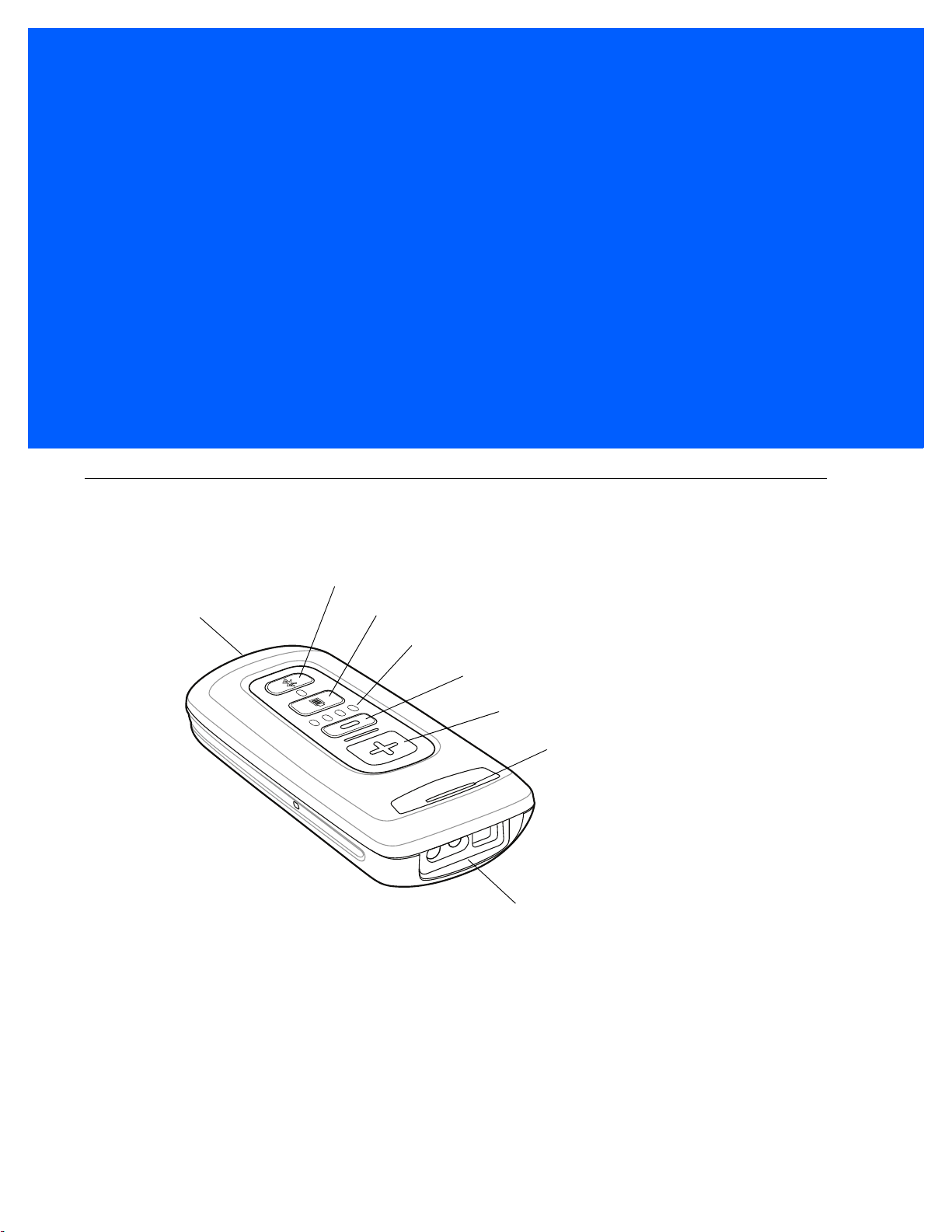
Scanner Window
Scan/Add Key
LED
Bluetooth Key / LED
Delete Key
Battery Level LEDs
Battery Level Key
Micro USB Port
Introduction
The CS4070 Scanner captures and stores bar codes for a variety of uses, and transmits bar code data to a
host via USB connection or Bluetooth.
Figure 1-1
This scanner supports the following host interfaces:
•
•
CS4070 Scanner
USB - The scanner connects to a USB host as a removable storage device, via a cradle or USB cable.
Bluetooth - The scanner supports Bluetooth HID connection to a host (the default) where the scanner
emulates a keyboard, as well as Serial Port Profile (SPP) connection where the scanner behaves as if
there is a serial connection.
1 - 2 CS4070 Scanner Product Reference Guide
Battery
Release Latch
Unpacking the Scanner
Carefully remove all protective material from the scanner and save th e shipping container for late r storage and
shipping. Verify that you received the following equipment:
•
CS4070
•
Lithium-ion battery
•
Micro USB cable
•
Quick Start Guide.
Inspect the equipment. If any equipment is missing or damaged, contact support. See page xviii for contact
information.
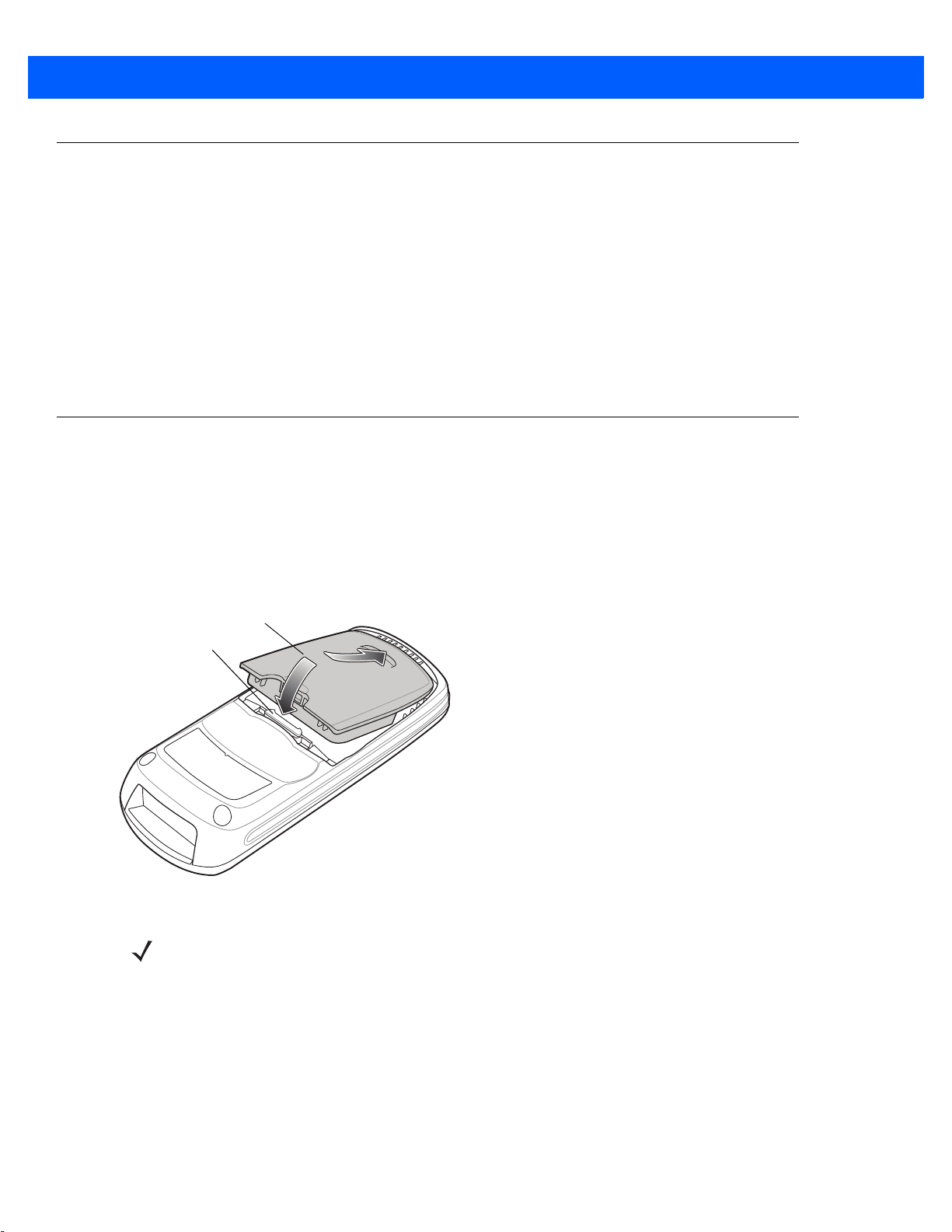
Inserting and Removing the Battery
Inserting the Battery
Before using the scanner, insert the lithium-ion battery provided with the device.
1. Insert the battery, bottom first, into the battery compartment in the back of the device.
2. Press the battery down into the battery compartment until the battery release latch snaps into place.
Figure 1-2
Inserting the Battery
NOTE Position the battery correctly, with the battery charging contacts pointing towards the bottom of the
scanner.

Getting Started 1 - 3
Removing the Battery
To remove the battery, pull the release latch upward with one finger, and use a finger from your other hand to
pull back on the indent in the bottom of the batter y housing. The batte ry rotates about the bottom edge and the
latch end of the battery pops up, enabling you to lift it out from the sides.
Figure 1-3
Lift Release Latch

1 - 4 CS4070 Scanner Product Reference Guide
Charging Batteries
Before using the CS4070 for the first time, charge the battery using the micro USB cable or a cradle until the
green charge status LED lights. See Table 2-1 on page 2-4 for charge status indications. For information about
the charging accessories available for the devic e, see Appendix B, Accessories.
NOTE If the battery is removed or replaced, the device cold boots. The internal back up battery retains the
real-time clock.
Charging the Battery in a CS4070
Use one of the following methods to charge the battery when installed in a CS4070:
•
Connect the micro USB cable to the micro USB port on the device , and the othe r end to a USB port on a
host computer. Note that the scanner can not scan when connected to a host computer.
•
Connect the micro USB cable to the micro USB port on the device, and the other end to a USB power
adapter plugged into an AC outlet.
•
Insert the CS4070 into a powered single-slot or 8-slot charging cradle. See Single- Slot CS4070 Charging
Cradle with Spare Battery Charger on page B-3 or Eight-Slot CS4070 Charging Cradle on page B-5 for
more information.
The CS4070 begins charging. The charge status LED flashes amber while charging, then turns solid green
when fully charged. See Table 2-1 on page 2-4 for charging indications.
Charging Spare Batteries
To charge a spare battery, insert the battery into a slot of a powered sp are batter y char ging accesso ry with th e
charging contacts facing down, contacting the charging pins in the cradle. See Single-Slot CS4070 Charging
Cradle with Spare Battery Charger on page B-3 or Eight-Slot Spare Battery Charger on page B-7.
The battery begins charging. The charge LED on the cradle lights to show the charge status.
Charging Temperature
IMPORTANT:
Charge batteries in temperatures from 0°C to 35°C (32°F to 95°F).
Note that at temperatures above 30°C the charging temperatur e is monitored and controlled by the de vice and
the charging accessory. Charging is halted at temperatures above 35°C.
The device or accessory indicates when charg ing is disa bled due to a bnormal temper atures via its LED and/or
battery icon. See Table 2-1 on page 2-4, Table B-2 on page B-4, and Table B-3 on page B-8.
Connecting to the Host Computer
Batch Connection
The micro USB cable enables communication between the CS4070 and a PC, and charges the battery in the
CS4070.
NOTE To enter batch scanning mode, see Batch Mode on page 3-44.
To connect the CS4070 to a USB device:
1. Connect the USB A end of the USB cable to a USB port of the host or device.
2. Connect the micro USB connector of the cable to the CS4070.
Getting Started 1 - 5
Figure 1-4
Micro USB Cable Communication
Bluetooth Connection: Development Options
NOTE Multiple scanners can connect to a single host via SPP or HID. The host application must sort the data it
receives from the scanner.
Serial Port Profile
This Bluetooth profile emulates a serial cable to provide a simply implemented wireless replacement for
existing RS-232 based serial communications applications, including familiar control signals. It is the preferred
communication profile implementation because accidental key strokes from the keyboard or touch screen on
the host are not entered into the bar code dat a str ea m .
Human Interface Device Emulation
This Bluetooth profile is a lightweight wrapper of the Human Interface Device protocol defined for USB. Data
transmitted from the Bluetooth scanner appears as keyboard entries to the Bluetooth host (Smartphone, PC,
etc).
NOTE Wedge data appears within whichever application has input focus.

1 - 6 CS4070 Scanner Product Reference Guide
Pairing
Pairing the CS4070 with a host device typically requires holding the Bluetooth button to place the scanner in
discoverable mode, then scanning a pairing PIN if required. Th e CS4 070 rem embers th e PIN fo r the last eigh t
devices to which it paired, and can establish connection to these devices without customer input after the initial
pairing.
NOTE When using the dongle, simply scan the pairing bar code on the dongle to connect. No PIN is required.
Note that the dongle allows a single connection only.
Supported Devices
The CS4070 supports connection to the following types of devices:
•
iOS
•
Android
•
Windows 8 Pro
•
Windows 7 Pro
•
Windows XP (Microsoft, Broadcom, and other commonly available Bluetooth stacks)
•
Windows RT
•
Windows Embedded Compact (CE7)
To pair to a Bluetooth-enabled host:
1. Press the scan button (+) to wake the scanner.
2. Press and hold the Bluetooth button until the scanner beeps and the blue LED begins to flash to indicate
that the scanner is discoverable by the host.
3. On the host, launch the Bluetooth pairing application and place the application into discover Bluetooth
device mode.
4. Select the CS4070 from the disco vered device list. The Bluetooth application may prompt you to scan a
PIN it generated, or for you to create and then scan the PIN.
5. If required, scan PIN Entry Bar Codes on page C-9 that correspond to the PIN, then scan Enter.
The Bluetooth button blinks slowly to indicate that the scanner paired with the host.
NOTE Bluetooth pairing suspends temporarily while charging via a USB cable. Disconnecting the cable
re-establishes Bluetooth pairing.
NOTE When pairing with an iPad, press the delete key (- ) on the CS4070 to toggle the virtual keyboard on and
off.
For pairing examples, see Appendix C, Bluetooth Connection Examples.
Getting Started 1 - 7
Unpairing
To temporarily unpair the scanner and host, press and hold the Bluetooth button for 2 seconds, then release.
This disables Bluetooth and the Bluetooth button stops blinking. Pressing the Bluetooth button again re-pairs
the scanner with the host.
NOTE If the Bluetooth button is held for longer than 5 seconds, the scanner terminates the wireless connection,
if already paired and connected to a host system. The scanner then enters discovery mode, searching for
a new host with which to pair and establish a new wireless connection.
To permanently unpair the scanner and host, scan Unpair on page 3-10. This allows the scanner to pair to a
different host device.
NOTE To enter batch scanning mode, see Batch Mode on page 3-44.
Deleting the CS4070 from the Device List
To delete the device from the discovered devices list, tap and old the device and select Delete.
Figure 1-5
Deleting Device

1 - 8 CS4070 Scanner Product Reference Guide
Configuring the Scanner
123Scan
To configure the scanner via 123Scan, use this utility to generate a 2D bar code with the desired configuration
options. Scan the bar code to configure the scanner with these options. Note that the CS4070 does not support
1D configuration bar codes. See Chapter 7, 123Scan and Software Tools.
Parameter Bar Codes and Config.ini
To configure the scanner:
1. Scan the parameter bar codes in Chapter 3, User Preferences and Chapter 5, Symbologies to customize
scanner operation.
2. For additional customization, edit the Config.ini file on the scanner using the options in Editing the
Configuration File on page 1-9.
3. When deploying the new configuration to multiple scanners, to ensure unique CS4070 serial numbers
appear in the host’s discovery window , edit the
blank (“BTName=”) to ensure that each scanner uses the default BT name of
Config.ini file to either remove the BTName entry or set it to
CS4070:<serial number>.
Staging Multiple Scanners
After creating a config.ini file for one “golden” scanner with all desired settings, create a copy of the file from
this scanner and copy it to other scanners via USB connection. Set the time and date on the “cloned” scanners
by scanning bar codes from Set Date and Time on page 3-6.
NOTE When deploying the new configuration to multiple scanners, to ensure unique CS4070 serial nu mbers
appear in the host’s discovery window, edit the Config.ini file to either remove the BTName entry or set it
to blank (“BTName=”) to ensure that each scanner uses the default BT name of CS4070:<serial number>.
Updating Scanner Firmware
To update scanner firmware:
1. Connect the micro USB cable from the host to the CS4070.
2. Copy the .dat and .bin files to the root directory of the scanner.
3. Disconnect the cable when the host indicates that it is safe to remove.
After several minutes the LED turns green to indicate that the firmware was successfully installed.

Editing the Configuration File
Use a text editor such as Notepad to set configuration values in the Config.ini editable text file in the
\Parameters folder on the CS4070. Table 1-1 lists the programmable contents of the file.
NOTE All values in the Config.ini file are hexadecimal.
NOTE If you make errors while editing the Config.ini file, the file LOG.TXT is created in the \Parameters folder.
Consult this log file to determine the errors and make corrections.
Getting Started 1 - 9
Table 1-1
Config.ini File Content
Name Description Values Default
AutoReconnect Enable or disable automatic Bluetooth
reconnection to dongle or another device.
BarcodeFile Name of file to store batched data. String BARCODES.TXT
BTName Bluetooth friendly name String CS4070
BTPin Bluetooth PIN code String 1234
BTProfile Selected Bluetooth profile 0 = HID
BtRfPower Controls Bluetooth radio output power
(100 m vs. 10 m)
BTSleep Time in seconds before device enters sleep
mode while paired to another Bluetooth
device if no activity is detected.
Note: Set this value equal to or less than the
Sleep
setting.
ButtonBT Enable or disable the Bluetooth button. 1 = Enabled
1 = Enabled
0 = Disabled
1 = SPP
2 = SSI
3 = MFi_SPP
4 = MFi_SSI
0 = Class 1
1 = Class 2
Word 14400 (4 hours)
0 = Disabled
Enabled
HID
Class 1
Enabled
ButtonMinus Enable or disable the delete (minus) button. 1 = Enabled
0 = Disabled
ButtonPlus Enable or disable the scan/add (plus) button. 1 = Enabled
0 = Disabled
CodeID Enable or disable saving CodeID in scanned
bar codes file.
ConnectionInterval Amount of time to try to establish
connection/auto-reconnect and the timeout
for discovery mode.
1 = Enabled
0 = Disabled
30 seconds
1 minute
2 minutes
5 minutes
Enabled
Enabled
Enabled
30 seconds

1 - 10 CS4070 Scanner Product Reference Guide
Table 1-1
Config.ini File Content (Continued)
Name Description Values Default
CountryKeyboardType Country keyboard code North American
Windows Belgian
French
Windows French
Windows German
Windows Canadian
Windows Spanish
Windows Italian
Windows Swedish
Windows UK
Windows Japan
Windows Portuguese
Brazil
Windows Swiss
German
Windows Swiss French
Windows Simplified
Chinese GBK
Windows Simplified
Chinese UTF-8
Windows Traditional
Chinese BIG5
Windows Traditional
Chinese UTF-8
Windows Russian
Windows Russian
Typewriter
North American
DateFormat Date format 0= MM/DD/YY
1 = DD/MM/YY
2 = MM/DD/YYYY
3 = DD/MM/YYYY
DisableProtectToggle Enable or disable the scan bar code
function.
HIDSecurity Set HID security
Notes: Some devices do not allow a
connection in HID mode if this is set to low.
Set security to low to connect to Android
devices in HID mode without entering a PIN
code.
KeystrokeDelay For HID only, set the delay, in milliseconds,
between emulated keystrokes.
Note: When pairing with the Android, set this
to 70 ms to avoid data loss.
LEDBlue Enable or disable the blue LED for normal
operations and wake up.
LEDGreen Enable or disable the green LED for normal
operations and wake up.
LEDRed Enable or disable the red LED for normal
operations and wake up.
1 = Enabled
0 = Disabled
2 = High (keyboard only
- secure simple pairing
capability)
3 = Low (no input/
no output - secure
simple pairing capability
Word (0 to 100) 0
1 = Enabled
0 = Disabled
1 = Enabled
0 = Disabled
1 = Enabled
0 = Disabled
MM/DD/YY
Disabled
High
Enabled
Enabled
Enabled

Getting Started 1 - 11
Table 1-1
Config.ini File Content (Continued)
Name Description Values Default
LEDAmber Enable or disable the amber LED for normal
operations and wake up.
Mute Mute beeper 1 = Enabled
PagerMotor
(CS4070HC only)
PagerMotorDuration
(CS4070HC only)
Prefix Add prefix to decode data.
ScanLED Enable of disable the LEDs that illuminate
Enable or disable the pager motor which
vibrates the sca nner for a period of time
upon successful decode.
Set the period of time for which the scanner
vibrates.
Note: This field must contain a printable
keystroke ASCII hex code as defined in
Table D-6 on page D-12
To program non-printable and non-ASCII
characters shown in the Appendix H, ASCII
Character Sets tables, use parameter bar
code programming in
.
3-61
while the laser scanner is active.
.
Data Options on page
1 = Enabled
0 = Disabled
0 = Disabled
1 = Enabled
0 = Disabled
150 - 750 msec 200 msec
Byte <none>
1 = Enabled
0 = Disabled
Enabled
Off
Enabled
Enabled
<Scanner Parameters> All other scanner parameters defined in this
guide. These parameters have
self-documenting names with associated
hexadecimal numbers and values. Multiple
entries are allowed. The format is:
<parameter name><hexadecimal parameter
number><hexadecimal parameter value>
For example:
Code39=00,01
UPC-A=01,01
UPC-E=02,01
Separator An ASCII character that acts as a delimiter in
the Barcode.txt file between the Time and
Date Stamp and the barcode data.
Sleep Time in seconds before device enters sleep
mode if no activity is detected.
Suffix Add suffix to decode data.
Note: This field must contain a printable
keystroke ASCII hex code as defined in
Table D-6 on page D-12
To program non-printable and non-ASCII
characters shown in the Appendix H, ASCII
Character Sets tables, use parameter bar
code programming in
3-61
.
.
Data Options on page
V ariable N/A
Byte ',’
Word 14400 (4 hours)
Byte <none>

1 - 12 CS4070 Scanner Product Reference Guide
Table 1-1
Config.ini File Content (Continued)
Name Description Values Default
TimeFormat Time format for data stored in batch.
Note: If you set this to blank, there is no time
and date stamp stored with batched data in
the Barcodes.txt file.
WakeUpBeep Enable or disable wake up beep. 1 = Enabled
WakeUpLED Enable or disable wake up LEDs. 1 = Enabled
ZeroOutHIDClassOfDevice Some versions of Broadcom stack
experience issues when connecting to HID
devices. Enable this feature if this is the
case.
1 = 12h
0 = 24h
2 = Blank or <Space>
0 = Disabled
0 = Disabled
1 = Enabled
0 = Disabled
24h
Disabled
Enabled
Disabled

CHAPTER 2SCANNING
Introduction
This chapter provides instructions for how to scan bar codes and send the data to a host. Beeper and LED
definitions are also included.
Scanning
See Chapter 1, Getting Started to install and program the scanner. To scan:
1. Aim the scanner at the bar code.
2. Press the scan (+) button.
Figure 2-1
3. Ensure the aiming dot is centered on the bar code.
The scanner beeps and the LED turns green to indicate a successful decode. See Table 2-1 and Table 2-2 for
beeper and LED definitions..
Scanning
NOTE The scanner cannot scan bar codes when it is connected to the host via the USB host cable.

2 - 2 CS4070 Scanner Product Reference Guide
NOTE Hold down the + button for 10 seconds to toggle the beeper functionality on and off.
Deleting Bar Codes
In batch mode, to delete a bar code aim the scanner at the bar code and press the delete ( - ) button.
Figure 2-2
Deleting a Bar Code in Batch Mode
Transmitting Bar Code Data to Host
Transferring Data from a Batch Scanner
The BarcodeFile.txt file within the \Scanned Barcodes directory on the scanner stores scanned bar code data.
To transfer data, perform one of the following:
•
Connect the scanner to the host via USB cable when in Batch Only mode (see Batch Mode on page
3-44) and use Windows Explorer to navigate to the scanner. Cut and paste the bar code data file to the
host.
•
Scan Send Batch Data on page 3-46 when the scanner is in a Standard Batch Mode (see Batch Mode
on page 3-44). The contents of the BarcodeFile.txt file transmit over Bluetooth to the host application.
IMPORTANTBefore scanning Send Batch Data, ensure the host application is ready to receive the
contents of the BarcodeFile.txt file or the data is lost because, for security reasons, the
scanner deletes this file after sending it. The CS4070 sends all Bluetooth data usin g the
standard encryption formats within the Bluetooth protocol.
NOTE When the scanner is in Batch ONLY Mode, Out of Range Batch Mode, or Standard Batch Mode , you
can also copy or cut and paste the BarcodeFile.txt file to the host.
Clearing Bar Code Data
To clear the bar code data, delete the BarcodeFile.txt file from the scanner, or scan the Clear Data bar code on
page 3-11.
NOTE The scanner does not allow changing the Batch Mode state until the BarcodeFile.txt file is deleted or
completely cleared.

Scanning 2 - 3
Autorun Feature
The scanner supports an autorun feature where you can bu ild an autor un.inf file to automatically copy the data
to the host upon connection. Autorun.inf is a text-based configuration file that defines, upon connecting the
scanner, which executable or application to run on the host, which icon represents the scanner, an d which
menu commands appear when you right-click the scanner icon from Windows Explorer. For more information,
search
autorun.inf on any search engine.
Transferring Data from a Bluetooth Scanner
When the scanner is paired to a host via Bluetooth, data transmits to the host after each scan and is not stored
on the device.
Out of Range Behavior
If the scanner moves out of range of the host, and does not re-pair with the host within the timeout period,
scanned data is lost and the scanner emits a 3-beep error tone.
When the radio loses connection, the Bluetooth LED stops its slow, consistent blinking and the beeper emits a
short high low beep. The Bluetooth LED blinks at a faster rate for a period of time while the device attempts to
reestablish pairing with the host, and when it returns within ra ng e the de vic e re pa irs. If repairing is
unsuccessful the Bluetooth LED stops blinking.
To manually reestablish paring when the device returns to range, press the Bluetooth LED button. Upon
Bluetooth pairing, the beeper emits a short low high beep and the Bluetooth LED starts its slow, consistent
blinking again.

2 - 4 CS4070 Scanner Product Reference Guide
User Interface Definitions
The scanner uses beeper and LED sequences to indicate various system events. Table 2-1 and Table 2-2
define these sequences and events.
LED Indications
Table 2-1
Bar Code Data Indications
Scan attempt Press scan (+)
Successful bar code scan Solid green Imager off
Delete bar code
(when in batch mode)
Successful bar code deletion Solid amber Imager off
Unsuccessful deletion - item
doesn't exist (when in batch
mode)
Clear all bar code data
(when delete (-) button enabled)
Successful clear all Solid amber Imager off
LED Indications
Function Performed User Action LED Feedback Other
Flashing green Imager on
button
Press & hold
delete (-) button
Hold delete (-)
button 3 seconds
past scan time
Flashing amber Imager on
Solid red Imager off
Flashing amber Imager on

Scanning 2 - 5
Table 2-1
Charging Indications
Battery charge status Press battery
Charge scanner Connect scanner
LED Indications (Continued)
Function Performed User Action LED Feedback Other
4 green Full charge (12 hours in a
charge button.
If scanner is in
sleep mode, press
scan (+) button to
wake it.
to a host PC USB
port.
Insert scanner in
charging cradle.
3 green Approximately 3/4 charge
2 green Approximately 1/2 charge
1 green Approximately 1/4 charge
Flashing amber Scanner connects in mass
Flashing amber The battery is above the low
Flashing red The battery is trickle charging
busy environment)
storage mode, auto-run
application on PC launches
battery threshold of 3.4 volts.
The scanner turns on if
removed from the charging
source.
but is well below the low
battery threshold of 3.4 volts.
The scanner does not turn on
if removed from the charging
source.
Charge complete Solid green The scanner turns on if
removed from the charging
source.
Charge error Connect scanner
to a host PC USB
port or insert
scanner in
charging cradle.
Solid amber The battery is above the low
battery threshold but is not
charging due to a faulty
battery or charging source.
Re-seat the scanner in the
charging cradle or connect it
to a host PC USB port. If the
problem persists replace the
charger or the battery.
Solid red The battery is not installed or
is faulty. Re-seat the scanner
in the charging cradle or
connect it to a host PC USB
port. If the problem persists
replace the battery.

2 - 6 CS4070 Scanner Product Reference Guide
Table 2-1
Data Protection Indications
Toggle data protection on or off
(when enabled)
Successful data protection setting Solid amber
Bluetooth Indications
Enable Bluetooth radio Hold Bluetooth
Bluetooth radio pairing Press Bluetooth
Bluetooth radio paired with host
and in range
Unpair scanner from host Hold Bluetooth
LED Indications (Continued)
Function Performed User Action LED Feedback Other
Press & hold both
scan (+) and
delete (-) buttons
for 6 seconds.
button.
button.
button for 2
seconds.
None
Rapidly flashing blue
LED
Slowly flashing blue
LED
Very slowly flashing
blue LED
Off
Bluetooth is enabled but has
not paired with a host.
Bluetooth radio out of range of
host
Bluetooth radio returns to
communication range of host
Special Conditions
Memory low scan Press & hold scan
Delete/Clear All Press & hold
Memory Full Scan Press & hold scan
Memory Full Delete/Clear All Press & hold
Data protection (enabled and on) Scan/function/
Unexpected failure Scan/function/dock Flashing red, green
Press any button. Very slowly flashing
(+) button.
delete (-) button.
(+) button.
delete (-) button.
host com
Blue LED rapidly
flashes for 2
minutes, then turns
off
blue LED
Flashing red, then
normal operation
Normal operation
Solid red
Normal operation
Rapidly flashing red
and amber for 5
seconds
Stops transmitting beacons.
Re-pairs device with host.
Contact support
Battery depleted Scan/function/dock None

Beeper Indications
Scanning 2 - 7
Table 2-2
Successful bar code scan Short high beep Imager off
Successful bar code deletion Short medium beep Imager off
Unsuccessful deletion - item doesn't
exist (when in batch mode)
Successful clear all Warble (high low high low)
Successful data protection setting Short long short beep
Connect scanner to a host PC USB
port to charge scanner
Enable Bluetooth radio Short beep Hold Bluetooth button
Bluetooth radio pairing Short low high beep
Bluetooth radio out of range of host Short high low beep Stops transmitting beacons
Bluetooth radio returns to
communication range of host
Bluetooth automatic reconnect to
host or disconnect from host
Beeper Indications
Function Performed Beeper Feedback Other
Long short short beep Imager off
Imager off
beep
Low high beep
Short low high beep Re-pairs device with host
2 short beeps
Auto-reconnect on page 3-12
be enabled
must
Attempt to scan when out of
Bluetooth radio range
Memory Full Scan Long beep for 5 seconds or
4 high beeps No Bluetooth transmission
until scan button released

2 - 8 CS4070 Scanner Product Reference Guide

CHAPTER 3USER PREFERENCES
*Medium Frequency
(1)
Feature/Option* Indicates Default
Option value
Introduction
This chapter describes each user preferen ce fea tu re and provides the programming bar codes for selecting
these features for the scanner.
The scanner ships with the settings shown in the User Preferences Default Table on page 3-2 (also see
Appendix A, Standard Default Parameters for all host device and miscellaneous scanner defaults). If the
default values suit the requirements, programming is not necessary. T o change thes e values, scan a single bar
code or a short bar code sequence. The new settings are stored in non-volatile memory and are preserved
when the scanner powers down.
To return all features to their default values, scan the Reset Factory Defaults bar code on page 3-5. Thro ughout
the programming bar code menus, default values are indicated with asterisks (
*).
Scanning Sequence Examples
In most cases, scan only one bar code to set a parameter value. For example, to set the beeper tone to high,
scan the High Frequency (beeper tone) bar code under Beeper Tone on page 3-37. The scanner issues a fast
warble beep and the LED turns green, indicating a successful parameter entry.
Other parameters, such as Data Transmission Formats, require scanning several bar codes. See the
parameter description for this procedure.
Errors While Scanning
Unless otherwise specified, if an error is made during a scanning sequence, re-scan the correct parameter.

3 - 2 CS4070 Scanner Product Reference Guide
User Preferences Default Parameters
Table 3-1 lists the defaults for user preference parameters. To change any option, scan the appropriate bar
code(s) provided in this chapter.
NOTE See Appendix A, Standard Default Parameters for all default parameters.
Table 3-1
Reset Factory Defaults N/A N/A N/A
Set Date N/A N/A N/A
Set Time N/A N/A N/A
Cancel Date and Time Settings N/A N/A N/A
Bluetooth Options
Bluetooth Friendly Name N/A N/A N/A
Pairing Bar Code Format N/A N/A N/A
Bluetooth Unpair N/A N/A N/A
Bluetooth Profile N/A N/A HID
Clear Data N/A N/A N/A
Auto-reconnect N/A N/A Enable
Connection Interval and Discovery Mode
Timeout
User Preferences Default Table
Parameter
Parameter
Number
1339 F8h 05h 3Bh 2 Minutes
SSI
Number
Factory Default
Page
Number
3-5
3-6
3-6
3-6
3-8
3-9
3-10
3-10
3-11
3-12
3-13
Link Supervision Timeout 1698 F4h 06h A2h 0.5 Seconds
Bluetooth HID Host Name Host 1: 1397
Host 2: 1398
Host 3: 1399
HID Security 911 F2h 8Fh High
Radio Output Power N/A N/A Class 1
Set HID CoD to Zero N/A N/A Disable
Bluetooth HID Keyboard Features
Country Keyboard Type 1392 F8h 05h 70h Windows North
HID Caps Lock Override 1372 F8h 05h 5Ch Disable
HID Ignore Unknown Characters 1373 F8h 05h 5Dh Enable
Host 1:
F8h 05h 75h
Host 2:
F8h 05h 76h
Host 3:
F8h 05h 77h
N/A
American
3-14
3-15
3-18
3-18
3-19
3-20
3-23
3-23

User Preferences 3 - 3
Table 3-1
Emulate Keypad 1374 F8h 05h 5Eh Disable
HID Keyboard FN1 Substitution 1375 F8h 05h 5Fh Disable
FN1 Substitution Values:
HID Function Key Mapping 1377 F8h 05h 61h Disable
Simulate Caps Lock 1378 F8h 05h 62h Disable
Convert Case 1379 F8h 05h 63h No Case Conversion
Fast Bluetooth HID Keyboard 1429 F8h 05h 95h Fast HID Enable
General Decoder Settings
Hand-Held Trigger Mode 138 8Ah Level (Standard)
Hand-Held Decode Aiming Pattern 306 F0h 32h Enable
Presentation Mode Field of View 609 F1h 61h Full
User Preferences Default Table (Continued)
Parameter
Key Category
Decimal Value
Parameter
Number
103
109
Number
67h
6Dh
SSI
Factory Default
N/A
Page
Number
3-24
3-25
3-25
3-26
3-26
3-27
3-28
3-29
3-30
3-31
Decoding Illumination 298 F0h 2Ah Enable
Direct Decode Indicator 859 F2h 5Bh Disab le
Low Light Scene Detection 810 F2h 2Ah No Low Light Scene
Detection
Beeper Volume 140 8Ch High
Beeper Tone 145 91h Medium Frequency
Mute Beeper N/A N/A Do Not Mute
Decode Pager Motor (CS4070HC only) 613 F1h 65h Enable
Decode Pager Motor Duration
(CS4070HC only)
Picklist Mode 402 F0h 92h Disabled Al way s
Fuzzy 1D Processing 514 F1h 02h Enable
Mirrored Image 624 F1h 70h Disable
Mobile Phone/Display Mode 716 F1h CCh Disable
PDF Prioritization 719 F4h F1h CFh Disable
PDF Prioritization Timeout 720 F1h D0h 200 ms
626 F1h 72h 200 msec
3-32
3-33
3-34
3-36
3-37
3-38
3-38
3-39
3-40
3-41
3-41
3-42
3-43
3-43
Batch Mode 544 F1h 20h Normal (Do Not
Batch Data)
Automatic Day/Night Mode 1393 F8h 05h 71h Disable
Automatic Day/Night Mode Start/Stop Time N/A N/A N/A
3-44
3-47
3-48

3 - 4 CS4070 Scanner Product Reference Guide
Table 3-1
Automatic Day/Night Mode Shift Profiles 1394 F8h 05h 72h Enable
Automatic Day/Night Mode 123Scan
Programmable Shift Start Time
Automatic Day/Night Mode 123Scan
Programmable Shift Stop Time
Out of Range Electric Fence Alarm 1426 F8h 05h 92h Disable
Out of Range Electric Fence Trigger
Timeout
Out of Range Electric Fence Alarm
Timeout
Continuous Bar Code Read 649 F1h 89h Disable
Unique Bar Code Reporting 723 F1h D3h Enable
Decode Session Timeout 136 88h 5.0 Sec
Timeout Between Decodes, Same Symbol 137 89h 0.5 Sec
User Preferences Default Table (Continued)
Parameter
Parameter
Number
1395 F8h 05h 73h N/A
1396 F8h 05h 74h N/A
1427 F8h 05h 93h 3 Seconds
1428 F8h 05h 94h 3 Seconds
SSI
Number
Factory Default
Page
Number
3-49
3-50
3-50
3-51
3-52
3-53
3-55
3-55
3-56
3-56
Timeout Between Decodes, Different
Symbols
Wi-Fi Friendly Mode 1299 F8h 05h 13h Disable
Wi-Fi Friendly Channel Exclusion 1297 F8h 05h 11h Use All Channels
Data Options
Transmit Code ID Character 45 2Dh None
Prefix Value 99, 105 63h, 69h 7013 <CR><LF>
Suffix 1 Value
Suffix 2 Value
Transmit “No Read” Message 94 5E Disable
Scan Data Transmission Format 235 EBh Data as is
Version Options
Send Firmware Version N/A N/A N/A
Send Scan Engine Version N/A N/A N/A
Send Dongle Version N/A N/A N/A
144 90h 0.1 sec
98, 104
100, 106
62h, 68h
64h, 6Ah
7013 <CR><LF>
3-57
3-58
3-59
3-61
3-62
3-62
3-64
3-63
3-65
3-65
3-65

Reset Factory Defaults
To reset the scanner to factory defaults, scan the following bar code. This rebuilds the configuration file from
program memory.
User Preferences 3 - 5
Reset Factory Defaults

3 - 6 CS4070 Scanner Product Reference Guide
Set Date and Time
NOTE You must scan the configuration bar codes to set the time and date stamp on the scanner. The time and
date can not be set or edited in the config.ini file. This setting persists for three months if the scanner is
not used.
Set Date
Scan the Set Date bar code, then scan six numeric digits in the format mmddyy
Date and Time Settings on page 3-7
NOTE To change the date format from mmddyy, see DateFormat on page 1-10.
(first two for the month, second two for the day, third two for the year).
Set Date
from
Numeric Bar Codes for
Set Time
Scan the Set Time bar code, then scan four numeric digits in the format hhmm from Numeric Bar Codes for
Date and Time Settings on page 3-7 representing the time a ccording to the 24 hour clock (first two for the h our ,
second two for the minute).
For example, to set the time to 8:45 in the morning, scan the following bar code, then scan 0, 8, 4, 5. To set the
time to 3:07 in the afternoon, scan 1, 5, 0, 7.
NOTE To change the time format between 12h and 24h, see TimeFormat on page 1-12.
Set Time
Cancel Date and Time Setting
Scan the Cancel Set Date/Time bar code to cancel the date and time settings.
Cancel Set Date/Time

Numeric Bar Codes for Date and Time Settings
0
2
User Preferences 3 - 7
1
3
4
5
6
7
8
9
Enter

3 - 8 CS4070 Scanner Product Reference Guide
Bluetooth Options
Bluetooth Friendly Name
You can set a meaningful name for the scanner that appears in the application during device discovery. The
default name is the scanner name followed by its serial number, e.g.,
Reset Factory Defaults reverts the scanner to this name; use 123Scan set defaults to maintain the
user-programmed name through a Set Defaults operation.
To set a new Bluetooth Friendly Name, scan the following bar code, then scan up to 23 characters from
Appendix G, Alphanume ric Bar Codes. If the name con tains less than 2 3 characters, scan End of Messa ge on
page G-7 after entering the name.
NOTE If your application allows you to set a device name, this takes preceden ce over the Bluetooth Friendly
Name.
CS4070: 123456789ABCDEF. Scanning
Bluetooth Friendly Name

User Preferences 3 - 9
Pairing Bar Code Content:
‘B’ + Bluetooth Address
B112233445566
Central/Peripheral Set Up
The scanner can be set up as a central or peripheral. When the scanner is set up as a peripheral, it is
discoverable and connectible to other devices. When the scanner is set up as a central, the Bluetooth ad dress
of the remote device to which a connection is req ue st ed is requ ir ed .
Peripheral
When the scanner is set up as a peripheral device, the scanner accepts an incoming connection request from
a remote device.
NOTE The number of scanners is dependent on the host’s capability.
Setting the scanner up as a peripheral typically requires holding the Bluetooth button to place the scanner in
discoverable mode, then scanning a pairing PIN. See Appendix C, Bluetooth Connection Examples for more
information.
Central
When the scanner is set up as a central, it initiates the radio connection to a peripheral device. Initiate the
connection in one of two ways:
•
Scan the bar code on the dongle. See Bluetooth to USB HID Dongle on page B-14.
•
Create and scan a pairing bar code with the remote device address. See Pairing Bar Code Format.
Pairing Bar Code Format
When connecting the scanner as a centra l to a remote Blueto oth device, you must create a pairing bar code for
the device. The Bluetooth address of the remote device must be known. Pairing bar codes are Code 128 bar
codes and are formatted as follows:
<Fnc 3>Bxxxxxxxxxxxx
where:
•
B (or LNKB) is the prefix
•
xxxxxxxxxxxx represents the 12-character Bluetooth address.
For example, if the remote device to which the scanner can connect has a Bluetooth address of
11:22:33:44:55:66, the n the pa irin g ba r co de is:

3 - 10 CS4070 Scanner Product Reference Guide
Bluetooth Unpair
Scan the following bar code to unpair the scanner from the host.
Bluetooth Profile
Scan a bar code below to select a Bluetooth profile:
•
Bluetooth HID Profile - The scanner emulates a keyboard. Includes USB Dongle Keyboard HID.
•
Bluetooth Serial Port Profile (SPP) - The scanner emulates a serial connection. Includes USB Dongle
CDC Host.
Unpair
•
Bluetooth SSI Profile - The scanner uses SSI. Includes SSI Dongle Over USB CDC.
•
Bluetooth MFi SPP - allows the scanner to connect to a serial port on iOS devices such as iPad and
iPhone.
•
Bluetooth MFi SSI - allows bi-directional (command and control) communication between the CS4070
and iOS devices.
IMPORTANTZebra CDC Windows device drivers must be loaded on the Windows host system when configuring
the scanner for USB Dongle CDC Host or SSI Dongle over USB CDC, and pairing and connecting to
the dongle. Download the Windows CDC drivers from
www.zebra.com/support.

Bluetooth Profile (continued)
*Bluetooth HID Profile
User Preferences 3 - 11
Bluetooth SPP
Bluetooth SSI Profile
Bluetooth MFi_SPP
Bluetooth MFi_SSI
Clear Data
Scan the following bar code to clear all batch bar code data on the scanner. This deletes the BarcodeFile.txt
from the scanner.
Clear Data

3 - 12 CS4070 Scanner Product Reference Guide
Auto-reconnect
When auto-reconnect is enabled, the scanner automatically tries to reconnect to a remote device when a
disconnection occurs that is due to the radio losing communication. This can hap pen if the scanner goe s out of
range with the remote device, or if the remote device powers down. The scanner tries to reconnect for the
period of time specified by the Connection Interval and Discovery Mode Timeout on page 3-13. During that
time the blue LED continues to blink.
If the auto-reconnect process fails due to page timeouts, the scanner sounds a timeout beep (long low/long
high) and turns off the radio. To re-start the auto-reconnect process press the scan ‘+’ or delete ‘-’ key.
If the auto-reconnect process fails because the remote device rejects the connection attempt, the scanner
sounds a connection reject beep sequence and deletes the remote pairing address. If this happens, you must
scan a pairing bar code to attempt a new connection to the remote device.
NOTE If you scan a bar code during the auto-reconnect sequence, the scanner emits a transmission error beep
sequence and does not transmit the data to the host. Normal scanning operation resumes after
re-establishing the connection. For error beep sequence definitions, see Table 2-2 on page 2-7.
Scan a bar code below to enable or disable automatic Blueto oth reconnection to the dongle or another device.
*Enable Auto-reconnect
Disable Auto-reconnect

User Preferences 3 - 13
Connection Interval and Discovery Mode Timeout
Parameter # 1339
SSI # F8h 05h 3Bh
Select the time period that the scanner attempts to connect or auto-reconne ct to another device, as well as the
timeout for discovery mode.
30 Seconds
(0)
*2 Minutes
(3)
1 Minute
(1)
5 Minutes
(2)

3 - 14 CS4070 Scanner Product Reference Guide
Link Supervision Timeout
Parameter # 1698
SSI # F4h 06h A2h
Scan one of the following bar codes to select how quickly the scanner senses that the Bluetooth radio lost
connection to the remote device. A lower value minimize s data loss a t the ed ge of the o perating rang e, while a
larger value minimizes disconnects due to the remote device not responding in time. If you are experiencing
occasional disconnects and the scanner is able to reconnect, increase the link supervision timeout value.
*0.5 Seconds
(800)
5 Seconds
(8000)
2 Seconds
(3200)
10 Seconds
(16000)
20 Seconds
(32000)

User Preferences 3 - 15
Bluetooth HID Host Name
Host 1: Parameter # 1397
SSI # F8h 05h 75h
Host 2: Parameter # 1398
SSI # F8h 05h 76h
Host 3: Parameter # 1399
SSI # F8h 05h 77h
You can enter up to three Bluetooth (BT) HID Host Names when configuring multiple scann er s us ing 1 23Scan
and/or the CS4070/ Parameters/support_table.ini file on the scanner.
By entering a BT HID Host Name, HID Security can be set to High so that authentication is disabled when
pairing and connecting to a Windows or Android device (i.e., no pin code entry is required to connect). To
enable authentication, leave this blank in 123Scan or delete the name fr om the
CS4070/Parameters/support_table.ini file.
Examples
Finding the Bluetooth HID Host Name on a Windows PC
1. In Windows Explorer, right-click Computer on the left-hand side of the dialog window.
2. Select Properties in the drop-down menu to open the Control Panel.
3. Enter the information indicated in the Computer name field (<Windows_XXXXXXX >) on the lower
right-hand side of the Control Panel home page into one of the three Bluetooth HID Host Name text boxes in 123Scan. This allows the CS4070 HID Security parameter to remain high while not having to enter a PIN code on the PC when pairing and connecting to the CS4070.
NOTE Windows_XXXXXXX is an example name used for illustration purposes only. Every Windows PC has a
unique computer name.

3 - 16 CS4070 Scanner Product Reference Guide
Figure 3-1
Entering Windows Host Name in 123Scan

User Preferences 3 - 17
Finding the Bluetooth HID Host Name on an Android Device
1. On the Android device, go to Settings > WiFi and turn on WiFi.
2. Tap the WiFi text to open the configuration screen.
3. Tap the WiFi Direct button, or open the options menu and tap WiFi Direct.
a. Note the name of the Android device under My device name, typically in the format Android_#####.
b. Enter this device name into one of the three Bluetooth HID Host Name text boxes in 123Scan. This
allows the CS4070 HID Security parameter to remain high while not having to enter a PIN code on the
Android device when pairing and connecting to the CS4070.
NOTE Android_##### is an example name used for illustration purposes only. Every Android device has a
unique My device name.
Figure 3-2
Entering Android Host Name in 123Scan

3 - 18 CS4070 Scanner Product Reference Guide
HID Security
Parameter # 911
SSI # F2h 8Fh
Scan one of the following bar codes to set HID security as follows:
•
High - keyboard only, secure simple pairing capability (select this for iOS devices)
•
Low - no input/no output, secure simple pairing capability (select this for Android devices)
NOTE Some devices do not allow a connection in HID mode if this is set to low.
Set security to low to connect to Android devices in HID mode without entering a PIN code.
*HID Security High
(2)
HID Security Low
(3)
Radio Output Power
The CS4070 uses a Class 1 Bluetooth radio with a transmission range of up to 100m . To place the radio in a
Class 2 operating mode to restrict the transmission range to 10m and reduce the effect of the radio on
neighboring wireless systems, scan the Bluetooth Class 2 bar code.
*Bluetooth Class 1
Bluetooth Class 2

User Preferences 3 - 19
Set HID CoD to Zero
Some versions of Broadcom stack experience issues when connecting to HID devices. If experiencing issues,
delete the CS4070 device from the Broadcom stack, enable ZeroOutHIDClassOfDevice on page 1-12 or scan
the Set HID CoD to Zero bar code below, and reconnect.
*Use HID CoD
Set HID CoD to Zero

3 - 20 CS4070 Scanner Product Reference Guide
Bluetooth HID Keyboard Features
Country Keyboard Type
Parameter # 1392
SSI # F8h 05h 70h
Select the country keyboard code type.
*Windows North American
(0)
Windows French
(9)
Windows Canadian
(11)
Windows Belgian French
(8)
Windows German
(10)
Windows Spanish
(12)

Country Keyboard Type (continued)
Windows Italian
(13)
User Preferences 3 - 21
Windows Swedish
(14)
Windows UK
(15)
Windows Portuguese Brazil
(18)
Windows Japan (ASCII)
(16)
Windows Swiss German
(19)

3 - 22 CS4070 Scanner Product Reference Guide
Country Keyboard Type (continued)
Windows Swiss French
(20)
Windows Simplified Chinese GBK
(21)
Windows Simplified Chinese UTF-8
(22)
Windows Traditional Chinese UTF-8
(24)
Windows Traditional Chinese BIG5
(23)
Windows Russian
(25)
Windows Russian Typewriter
(32)

User Preferences 3 - 23
HID CAPS Lock Override
Parameter # 1372
SSI # F8h 05h 5Ch
When enabled, the case of the data is preserved regardless of the state of the caps lock key. This setting is
always enabled for the “Japanese, Windows (ASCII)” keyboard type and can not be disabled.
*Do Not Override Caps Lock Key (Disable)
(0)
Override Caps Lock Key (Enable)
(1)
HID Ignore Unknown Characters
Parameter # 1373
SSI # F8h 05h 5Dh
Unknown characters are characters the host does not recognize. When Send Bar Codes With Unknown
Characters is scanned, all bar code data is sent except for unknown characters, and no error beeps sound.
When Do Not Send Bar Codes With Unknown Characters is scanne d, bar codes containing at least one
unknown character are not sent to the host, and an error beep sounds.
*Send Bar Codes With Unknown Characte rs
(Enable)
(1)
Do Not Send Bar Codes With Unknown Characters
(Disable)
(0)

3 - 24 CS4070 Scanner Product Reference Guide
Emulate Keypad
Parameter # 1374
SSI # F8h 05h 5Eh
When enabled, all characters are sent as ASCII sequences over the numeric keypad. For example, ASCII A is
sent as "ALT make" 0 6 5 "ALT Break."
*Disable Keypad Emulation
(0)
Enable Keypad Emulation
(1)

User Preferences 3 - 25
HID Keyboard FN1 Substitution
Parameter # 1375
SSI # F8h 05h 5Fh
When enabled, this parameter allows replacement of any FN1 character in an EAN128 bar code with a key
category and value chosen by the user. See FN1 Substitution Values to set the key category and key value.
*Disable Keyboard FN1 Substitution
(0)
Enable Keyboard FN1 Substitution
(1)
FN1 Substitution Values
Key Category Parameter # 103
SSI # 67h
Decimal Value Parameter # 109
SSI # 6Dh
Enabling HID Keyboard FN1 Substitution substitutes any FN1 character (0x1d) in an EAN128 bar code with a value. This value defaults to 7013 (Enter Key).
When using host commands to set the FN1 substitution value, set the key category parameter to 1, then set
the 3-digit keystroke value. See Table H-1 on page H-1 for the desired value.
To select a FN1 substitution value via bar code menus:
1. Scan the bar code below.
Set FN1 Substitution Value
2. Locate the keystroke desired for FN1 Substitution in Table H-1 on page H-1. Enter the 4-digit ASCII value
by scanning each digit in Appendix F, Numeric Bar Codes.
To correct an error or change the selection, scan Cancel.

3 - 26 CS4070 Scanner Product Reference Guide
HID Function Key Mapping
Parameter # 1377
SSI # F8h 05h 61h
ASCII values under 32 are normally sent as co ntrol-ke y se quences. When this p aramete r is enable d, the keys
in bold are sent in place of the standard key mapping (see Table H-1 on page H-1).
Table entries that do not have a bold entry remain the same whether or not this parameter is enabled.
*Disable Function Key Mapping
(0)
Enable Function Key Mapping
(1)
Simulated Caps Lock
Parameter # 1378
SSI # F8h 05h 62h
When enabled, the scanner inverts upper and lower case characters on the scanner bar code as if the Caps
Lock state is enabled on the keyboard. This inversion is done regardless of the current state of the keyboard
Caps Lock state.
*Disable Simulated Caps Lock
(0)
Enable Simulated Caps Lock
(1)

Convert Case
Parameter # 1379
SSI # F8h 05h 63h
When enabled, the scanner converts all bar code data to the selected case.
*No Case Conversion
(0)
User Preferences 3 - 27
Convert All to Upper Case
(1)
Convert All to Lower Case
(2)

3 - 28 CS4070 Scanner Product Reference Guide
Fast Bluetooth HID Keyboard
Parameter # 1429
SSI # F8h 05h 95h
Enable this to transmit Bluetooth HID keyboard data at a faster rate.
NOTE Disable this if the connected Bluetooth HID host displays multiple characters or drops characters.
*Enable Fast Bluetooth HID Keyboard
(1)
Disable Fast Bluetooth HID Keyboard
(0)

General Decoder Settings
Hand-Held Trigger Mode
Parameter # 138
SSI # 8Ah
Select one of the following trigger modes for the scanner.
•
Standard (Level) - A trigger press (i.e., (+) or (-) button) activates decode processing. Decode
processing continues until the bar code decodes, you release the trigger, or the decode session times
out.
•
Presentation (Blink) - The scanner activates decode processing when it detects a bar code in its field of
view. After a period of non-use, the scanner enters a low power mode, in which the LEDs turn off until the
scanner senses motion.
IMPORTANTPresentation (Blink) mode cannot be enabled if the scanner system is in either a Bluetooth SSI
Profile mode or a Bluetooth MFi_SSI Profile mode. See Bluetooth Profile on page 3-10. The scanner
sounds an error beep and leaves the Hand-Held Trigger Mode in its present state.
User Preferences 3 - 29
Likewise, if the Hand-Held Trigger Mode is set to Presentation (Blink) mode and you attempt to
configure the scanner for Bluetooth SSI Profile or Bluetooth MFi_SSI Profile, the scanner sounds an
error beep and leaves Hand-Held Trigger Mode set to Presentation (Blink) mode.
•
Auto Aim - This trigger mode projects the aiming dot when you lift the scanner. A trigger press activates
decode processing. After 2 seconds of inactivity the aiming dot shuts off.
*Level (Standard)
(0)
Presentation (Blink)
(7)
Auto Aim
(9)

3 - 30 CS4070 Scanner Product Reference Guide
Hand-Held Decode Aiming Pattern
Parameter # 306
SSI # F0h 32h
Select Enable Hand-Held Decode Aiming Pattern to project the aiming dot during bar code capture, or
Disable Hand-Held
NOTE With Picklist Mode on page 3-40 enabled, the decode aiming dot flashes even when the Hand-Held
Decode Aiming Pattern to turn the aiming dot off.
Decode Aiming Pattern is disabled.
*Enable Hand-Held Decode Aiming Pattern
(2)
Disable Hand-Held Decode Aiming Pattern
(0)

User Preferences 3 - 31
Presentation Mode Field of View
Parameter # 609
SSI # F1h 61h
In presentation mode, by default the scanner searches the larger are a of the aimi ng pattern ( Full Fiel d of View).
To search for a bar code in a smaller region around the aiming dot’s center in order to speed search time,
select
Small Field of View or Medium Field of View.
Small Field of View
(0)
*Full Field of View
(2)
Medium Field of View
(1)

3 - 32 CS4070 Scanner Product Reference Guide
Decoding Illumination
Parameter # 298
SSI # F0h 2Ah
Selecting Enable Decoding Illumination causes the scanner to flash illumination to aid decoding. Select
Disable Decoding Illumination to prevent the scanner from using decoding illumination.
Enabling illumination usually results in superior images. The effectiveness of the illumination decreases as the
distance to the target increases.
*Enable Decoding Illumination
(1)
Disable Decoding Illumination
(0)

User Preferences 3 - 33
Direct Decode Indicator
Parameter # 859
SSI # F2h 5Bh
This feature is only supported in Auto Aim and Standard (Level) trigger modes. Scan a bar code below to
select optional blinking of the illumination on a successful decode:
•
Disable Direct Decode Indicator - illumination does not blink on a successful decode.
•
1 Blink - illumination blinks once upon a successful decode.
•
2 Blinks - illumination blinks twice upon a successful decode.
*Disable Direct Decode Indicator
(0)
2 Blinks
(2)
1 Blink
(1)

3 - 34 CS4070 Scanner Product Reference Guide
Low Light Scene Detection
Parameter # 810
SSI # F2h 2Ah
This parameter allows the scanner to detect motion in dim to dark illumination environments when in
presentation mode.
NOTE If both Low Light Scene Detection and Decoding Illumination are enabled, Decoding Illumination takes
precedence.
•
No Low Light Scene Detection: The scanner attempts to detect motion as best it can with the aim dot
and illumination turned off when the scanner is idle.
•
Aiming Dot Low Light Assist Scene Detection: Illumination is turned off, but the aim dot is turned on
when the scanner is idle to assist in scene detection.
•
Dim Illumination Low Light Assist Scene Detection: The aim dot is turned off, but illumination is
turned on at a dim level to assist in scene detection.
*No Low Light Assist Scene Detection
(0)
Dim Illumination Low Light Assist Scene De tection
(2)
Aiming Dot Low Light Assist Scene Detection
(1)

User Preferences 3 - 35
Parameter Bar Code Scanning
Parameter # 236
To disable the decoding of parameter bar codes, including the Set Defaults parameter bar codes, scan the
Disable Parameter Scanning bar code below. To enable decoding of parameter bar codes, scan Enable
Parameter Scanning.
*Enable Parameter Bar Code Scanning
(1)
Disable Parameter Bar Code Scanning
(0)
Beep After Good Decode
Parameter # 56
Scan a bar code below to select whether or not the scanner beeps after a good decode. If selecting Do Not
Beep After Good Decode, the beeper still operates during parameter menu scanning and to indicate error
conditions.
*Beep After Good Decode (Enable)
(1)
Do Not Beep After Good Decode (Disable)
(0)

3 - 36 CS4070 Scanner Product Reference Guide
Beeper Volume
Parameter # 140
SSI # 8Ch
To select a decode beep volume, scan the appropriate bar code.
Low Volume
(2)
Medium Volume
(1)
*High Volume
(0)

Beeper Tone
Parameter # 145
SSI # 91h
To select a decode beep frequency (tone), scan the appropriate bar code.
Low Frequency
(2)
User Preferences 3 - 37
*Medium Frequency
(1)
High Frequency
(0)

3 - 38 CS4070 Scanner Product Reference Guide
Mute Beeper
Scan the Mute Beeper bar code to mute the beeper.
NOTE Scan the appropriate bar codes that follow to mute the beeper and/or disable the pager, and/or use the
config.ini file to disable all LEDs, when using the following SSI commands for scanner command and
control applications:
• SSI Beeper command
• Pager Motor Activation command
• LED commands
• CMD_ACK_ACTION command
Mute Beeper
(1)
*Do Not Mute Beeper
(0)
Decode Pager Motor (CS4070HC only)
Parameter # 613
SSI # F1h 65h
The scanner includes a pager motor which, when enabled, vibrates the scanner for a period of time when a
successful decode occurs.
Scan a bar code below to enable or disable the pager motor. If enabled, scan the appropriate bar code to set
the period of time in which to vibrate the scanner using Decode Pager Motor Duration (CS4070HC only).
Pager Motor Disable
(0)
*Pager Motor Enable
(1)

Decode Pager Motor Duration (CS4070HC only)
Parameter # 626
SSI # F1h 72h
150 msec
(15)
User Preferences 3 - 39
*200 msec
(20)
250 msec
(25)
400 msec
(40)
300 msec
(30)
500 msec
(50)

3 - 40 CS4070 Scanner Product Reference Guide
Decode Pager Motor Duration (continued)
600 msec
(60)
Picklist Mode
750 msec
(75)
Parameter # 402
SSI # F0h 92h
Picklist mode enables the scanner to decode only bar codes aligned under the center of the aiming pattern.
Select one of the following picklist modes:
•
Disabled Always - Picklist mode is always disabled.
•
Enabled Always - Picklist mode is always enabled.
*Disabled Always
(0)
Enabled Always
(2)

User Preferences 3 - 41
Fuzzy 1D Processing
Parameter # 514
SSI # F1h 02h
This option is enabled by default to optimize decode performance on 1D bar codes, including damaged and
poor quality symbols. Disable this only if you experience time delays when decoding 2D bar codes, or in
detecting a no decode.
*Enable Fuzzy 1D Processing
(1)
Disable Fuzzy 1D Processing
(0)
Mirrored Image
Parameter # 624
SSI # F1h 70h
Enable this to scan images in reverse, or mirrored, as if seen through a mirror. This mode is useful in
applications requiring scanning through a mirror and using symbologies that do not decode in reverse.
*Disable Mirrored Image
(0)
Enable Mirrored Image
(1)

3 - 42 CS4070 Scanner Product Reference Guide
Mobile Phone/Display Mode
Parameter # 716
SSI # F1h CCh
This mode improves bar code reading performance with target bar codes displayed on mobile phones and
electronic displays.
*Disable Mobile Phone/Display Mode
(0)
Enable Mobile Phone/Display Mode
(3)

User Preferences 3 - 43
PDF Prioritization
Parameter # 719
SSI # F4h F1h CFh
Enable this feature to delay decoding a 1D bar code (Code 128 of 8 to 25 characters length) by the value
specified in PDF Prioritization Timeout. During that time the scanner attempts to decode a PDF417 symbol
(e.g., on a US driver's license), and if successful reports this only. If it does not decode (can not find) a PDF417
symbol, it reports the 1D symbol after the timeout. The 1D symbol must be in the device’s field of view for the
scanner to report it. This parameter does not affect decoding other symbologies.
*Disable PDF Prioritization
(0)
Enable PDF Prioritization
(1)
PDF Prioritization Timeout
Parameter # 720
SSI # F1h D0h
When PDF Prioritization is enabled, this timeout specifies how long the scanner attempts to decode a PDF417 symbol before reporting the 1D bar code in the field of view.
Scan the following bar code, then scan four digits from Appendix F, Numeric Bar Codes that specify the timeout
in milliseconds. For example, to enter 400 ms, scan the following bar code, then scan 0400. The range is 0 to
5000 ms, and the default is 200 ms.
PDF Prioritization Timeout

3 - 44 CS4070 Scanner Product Reference Guide
Batch Mode
Parameter # 544
SSI # F1h 20h
When a cordless scanner is configured for batch mode, it attempts to store bar code data until transmission is
initialized, or the batch storage buffer is full (i.e., the Barcode.txt file is at maximum memory on the CS4070
only). Parameter bar codes are not stored. When a bar code is saved successfully, a good decode beep
sounds and the LED flashes green. If the scanner is unable to store a new bar code, a long beep sounds until
the scan button is released, indicating the scanner is out of memory.
IMPORTANTIf the batch mode selection is changed while there is batched data, the new batch mode
takes effect only after all the previously batched data is sent.
NOTE Always delete the Barcode.txt file before changing the batch mode state, either by holding the
delete key (- ) for 3 seconds, or scanning Clear Data on page 3-11.
Modes of Operation
•
Normal Batch Mode (default) - The scanner does not batch decoded data but transmits all decoded
data to the host over Bluetooth. If the scanner is not paired to a host and you attempt to scan and decode
a bar code, the scanner emits 4 short high beeps.
•
Out of Range Batch Mode - The scanner batches data whenever it loses connection to a remote
device, moves out of range, or is not paired. It suppresses batching decoded data if paired to a remote
device and transmits decoded data to the ho st de vic e.
NOTE Transmission halts if the scanner moves out of range. When the scanner moves backs into range, it
automatically re-connects to the Bluetooth host and resumes transmission. Scanning is disabled until all
batched data is sent to the host.
NOTE In this mode, if an abnormal Bluetooth termination occurs (e.g., removing the battery) while the CS4070 is
transmitting batched data over Bluetooth, the scanner resends the data on a reset and auto-reconnection
to ensure that no data is lost.
•
Standard Batch Mode - The scanner begins storing bar code data after scanning the Enter Batch
Mode bar code. Scan Send Batch Data to trigger data transmission an d dump the contents of the
Barcode.txt file stored in \CS4070<drive>:\Scanned Barcodes\.
•
Batch Only Mode - The scanner radio is off (never turned on) and the scanner stores all bar code data.
NOTE To dump the batched data stored in the /CS4070/Scanned Barcodes/Barcode.txt file, connect via USB
and either run the autorun.ini Windows script (see Autorun Feature on page 2-3) to copy and paste the
data into another PC program, OR cut and paste the file onto another network drive.
CAUTION If you copy and paste the Barcode.txt file from the CS4070 scanner to a network drive or a local PC
drive, delete the file afterward. The scanner does not change the batch mode state if the Barcode.txt
has stored batch data.

Batch Mode (continued)
*Normal Batch Mode
(0)
User Preferences 3 - 45
Out of Range Batch Mode
(1)
Standard Batch Mode
(2)
Batch Only Mode
(3)

3 - 46 CS4070 Scanner Product Reference Guide
Batch Action Bar Codes
•
In Standard Batch Mode, scan Enter Batch Mode to begin batching data. This stores the decoded data
in the /CS4070/Scanned Barcodes/Barcode.txt file on the device.
•
In Standard Batch Mode, scan Send Batch Data to send all stored batch data to the Bluetooth host
system.
CAUTION The scanner sounds 4 short high beeps if you scan Send Batch Data when the scanner is out of
range, when the scanner contains no batch data, or if the scanner is configured in Normal Batch
Mode or Batch Only Mode.
NOTE A carriage return (i.e., ASCII hex code = 0x0D / extended keypad ENTER key) keystroke is automatically
appended to the end of scanned data in the /CS4070/Scanned Barcodes/Barcodes.txt file and when
transmitted to the host system, the receiving host program (e.g., Microsoft Word, Notepad, Microsoft
Excel) displays the batch data in exactly the same format as it appears in the Barcodes.txt file. If this does
not happen, enable Bluetooth HID Function Key Mapping on page 3-26 or USB Dongle Function Key
Mapping on page 4-11.
Enter Batch Mode
Send Batch Data

User Preferences 3 - 47
Automatic Day/Night Mode
Parameter # 1393
SSI # F8h 05h 71h
Scan Enable Automatic Day/Night Mode to mute the beeper for all actions defined in Table 2-2 on page 2-7
from the Automatic Day/Night Start Time to the Automatic Day/Night Mode Stop Time OR based on the
Automatic Day/Night Mode Shift Profiles setting. This also enables the Decode Pager Motor ( CS4070HC o nly)
during this time period.
NOTE There are two ways to temporarily disable Night Mode (Night Mode start/stop times remain intact):
• Scan *Do Not Mute Beeper (0) on page 3-38 or
• Hold the scan (+) button for greater than 10 seconds.
Night Mode is re-enabled (i.e., the beeper is muted) on pressing the scan (+) button for greater than 10
seconds or on the next Au to ma tic Day/Night Mode start time.
CAUTION If this feature is enabled, the scanner sounds an error beep if the scanner Real Time Clock (RTC) is
not synchronized with the PC RTC. In this case, the Automatic Day/Night Mode start and stop times
may not trigger at the correct times. Use the RTCSync.exe utility on www.zebra.com/support to
synchronize the scanner and PC RTC from a factory defaults state or after removing and re-installing
the battery.
Enable Automatic Day/Night Mode
(1)
*Disable Automatic Day/Night Mode
(0)

3 - 48 CS4070 Scanner Product Reference Guide
Automatic Day/Night Mode Start/Stop Time
To set the Automatic Day/Night Mode start and stop time:
1. Scan the Automatic Day/Night Mode Start Time bar code.
2. Scan four Numeric Bar Codes for Date and Time Settings on page 3-7 representing the start time in the
format hhmm for the time according to the 24 hour clock (hh for the hour, mm for the minute).
3. Scan the Automatic Day/Night Mode Stop Time bar code.
4. Scan four Numeric Bar Codes for Date and Time Settings on page 3-7 representing the stop time in the
format hhmm for the time according to the 24 hour clock (hh for the hour, mm for the minute).
For example, to set the start time to 8:15 in the morning and th e sto p tim e to 5:07 in the afternoon, scan
Automatic Day/Night Mode Start Time, scan 0, 8, 1, 5, scan Automatic Day/Night Mode Stop Time, and
then scan 1, 7, 0, 7.
NOTE These times are set based on the CS4070 Real Time Clock settings. Ensure the Real Time Clock on the
scanner reflects the correct time zone. To set the Real Time Clock on the scanner use the RTCSync.exe
utility on www.zebra.com/support.
Automatic Day/Night Mode Start Time
Automatic Day/Night Mode Stop Time

User Preferences 3 - 49
Automatic Day/Night Mode Shift Profiles
Parameter # 1394
SSI # F8h 05h 72h
Scan one of the following bar codes to set the start and stop times for the Automatic Day/Night Mode feature.
•
Enable Shift 1 - 8 PM (20:00) to 8 AM (08:00)
•
Enable Shift 2 - 11 PM (23:00) to 4 AM (04:00)
•
Enable Shift 3 - 1 AM (01:00) to 8 AM (08:00)
•
24 Hour Shift - The scanner enters Automatic Day/Night Mode at 8:00 PM in the evening and remains in
this mode until 8:00 PM the following evening. It then becomes inactive over the next 24 hour perio d from
8:00 PM to 8:00 PM, and repeats this cycle until disabled.
*Enable Shift 1
(0)
Enable Shift 3
(2)
Enable Shift 2
(1)
24 Hour Shift
(3)

3 - 50 CS4070 Scanner Product Reference Guide
Automatic Day/Night Mode 123Scan Programmable Shift Start Time
Parameter # 1395
SSI # F8h 05h 73h
Use Zebra's 123Scan tool to program the Automatic Day/Night Mode shift start time. If Automatic Day/Night
Mode on page 3-47 is enabled, the scanner enters Night Mode at this start time. The beeper is muted and the
vibration pager motor feedback is active until the programmed shift stop time.
To set the start time, enter military time in the range of 0001 (12:01 AM) to 2400 (12:00 AM). For example, to
start Night Mode at 4:00 PM, enter 1600 in the 123Scan text box for this parameter.
For more information, seeChapter 7, 123Scan and Software Tool s or go to: www.zebra.com/123Scan
.
Automatic Day/Night Mode 123Scan Programmable Shift Stop Time
Parameter # 1396
SSI # F8h 05h 74h
Use Zebra's 123Scan tool to program the Automatic Day/Night Mode shift stop time. If Automatic Day/Night
Mode on page 3-47 is enabled, the scanner exits night mode and enters Day Mode at this time. The beeper is
no longer muted and the vibration pager motor feedback is inactive during Day Mode.
To set the stop time, enter military time in the range of 0001 (12:01 AM) to 2400 (12:00 AM). For example, to
stop Night Mode at 8:00 AM, enter 2000 in the 123Scan text box for this parameter.
For more information, seeChapter 7, 123Scan and Software Tool s or go to: www.zebra.com/123Scan
.

User Preferences 3 - 51
Out of Range Electric Fence
Out of Range Electric Fence Alarm
Parameter # 1426
SSI # F8h 05h 92h
This feature prevents scanners from going missing from a fixed location. Enable this to create an alarm that
generates a constant beep tone, vibration feedba ck, and rapidly flashes the LED between red and amber if th e
scanner moves out of range of a Bluetooth host system for a programmable amount of time.
NOTE To turn the alarm off, press and hold the minus button for greater than three seconds.
NOTE This alarm is automatically disabled if Batch Mode on page 3-44 is set to Standard Batch Mode (i.e., after
scanning the Enter Batch Mode bar code), Out of Range Batch Mode, or Batch Mode Only.
Enable Out of Range Electric Fence Alarm
(1)
*Disable Out of Range Electric Fence Alarm
(0)

3 - 52 CS4070 Scanner Product Reference Guide
Out of Range Electric Fence Trigger Timeout
Parameter # 1427
SSI # F8h 05h 93h
Scan one of the following bar codes to set the amount of time the scanne r can be out of range before the a larm
triggers.
For example, if the scanner moves out o f range of the Bluetoo th host and re mains out of r ange for gre ater than
three consecutive seconds (default), the alarm triggers. If the scanner moves back into range in less than three
consecutive seconds, this timer resets and th e ala rm do es no t trigg er.
0 Seconds
(0)
5Seconds
(2)
30 Seconds
(4)
*3 Seconds
(1)
10 Seconds
(3)
1 Minute
(5)

Out of Range Electric Fence Trigger Timeout (continued)
3 Minutes
(6)
User Preferences 3 - 53
5 Minutes
(7)
Out of Range Electric Fence Alarm Timeout
Parameter # 1428
SSI # F8h 05h 94h
Scan one of the following bar codes to set the amount of time the alarm sounds once triggered.
NOTE The alarm shuts down under any one of the following conditions:
• This Out of Range Electric Fence Timeout occurs.
• You hold the minus button for greater than three seconds and then release it.
• The scanner comes back into range.
• The scanner is placed into Standard Batch Mode, an Out of Range Batch Mode, or a Batch Only Mode.
• The scanner is connected to a new host.
This alarm is disabled if the scanner is placed into a Batch Mode on page 3-44.
*3 Seconds
(0)
5 Seconds
(1)

3 - 54 CS4070 Scanner Product Reference Guide
Out of Range Electric Fence Alarm Timeout (continued)
10 Seconds
(2)
30 Seconds
(3)
1 Minute
(4)
5 Minutes
(6)
2 Minutes
(5)
10 Minutes
(7)

Continuous Bar Code Read
Parameter # 649
SSI # F1h 89h
Enable this to report every bar code while the scan (+) button is held.
NOTE Zebra strongly recommends enabling Picklist Mode on page 3-40 with this feature. Disabling Picklist
Mode can cause accidental decodes when more than one bar code is in the scanner's field of view.
NOTE Enabling this feature disables deleting batch data from the Barcode.txt batch file by pressing the delete
(minus) key. To clear data in Continuous Bar Code Read mode, see Clear Data on page 3-11.
*Disable Continuous Bar Code Read
(0)
User Preferences 3 - 55
Enable Continuous Bar Code Read
(1)
Unique Bar Code Reporting
Parameter # 723
SSI # F1h D3h
Enable this to report only unique bar codes while the scan (+) button is held. This option only applies when
Continuous Bar Code Read is enabled.
Disable Continuous Bar Code Read Uniqueness
(0)
*Enable Continuous Bar Code Read Uniqueness
(1)

3 - 56 CS4070 Scanner Product Reference Guide
Decode Session Timeout
Parameter # 136
SSI # 88h
This parameter sets the maximum time decode processing continues during a scan attempt. It is
programmable in 0.1 second increments from 0.5 to 5.0 seconds. The default timeout is 5.0 seconds.
To set a Decode Session Timeout, scan the following bar code. Next, scan two numeric bar codes from
Appendix F, Numeric Bar Codes that correspond to the desired on time. Enter a leading zero for single digit
numbers. For example, to set a Decode Sessio n Timeout of 0.5 seconds, scan the bar code belo w, then scan
the 0 and 5 bar codes. To correct an error or change the selection, scan Cancel on page F-3
Decode Session Timeout
.
Timeout Between Decodes, Same Symbol
Parameter # 137
SSI # 89h
Use this option in Continuous Bar Code Read mode to prevent the beeper from continuously beeping when a
symbol is left in the scanner’s field of view. The bar code must be out of the field of view for the timeout period
before the scanner reads the same consecutive symbol. It is programmable in 0.1 secon d increments fr om 0.0
to 5.0 seconds. The default interval is 0.5 seconds.
To select the timeout between decodes for the same symbol, scan the bar code below, then scan two numeric
bar codes from Appendix F, Numeric Bar Codes that correspond to the desired interval, in 0.1 second
increments.
Timeout Between Decodes, Same Symbol

Timeout Between Decodes, Different Symbols
User Preferences 3 - 57
Parameter # 144
SSI # 90h
Use this option in presentation mode or Continuous Bar Code Read to control the time the scanner is inactive
between decoding different symbols. It is programmable in 0.1 second increments from 0.1 to 5.0 seconds.
The default is 0.1 seconds.
To select the timeout between decodes for different symbols, scan the bar code below, then scan two numeric
bar codes from Appendix F, Numeric Bar Codes that correspond to the desired interval, in 0.1 second
increments.
NOTE Timeout Between Decodes, Different Symbols cannot be greater than or equal to the Decode Session
Timeout.
Timeout Between Decodes, Different Symbols

3 - 58 CS4070 Scanner Product Reference Guide
Wi-Fi Friendly Mode
Parameter # 1299
SSI # F8h 05h 13h
Scanners configured for Wi-Fi friendly mode behave as follows:
•
The scanner remains in sniff mode, and exits sniff mode only during firmware update.
•
If any Wi-Fi channel is excluded from the hopping sequence, AFH turns off.
•
Scanner (and dongle) avoid the selected Wi-Fi channels after establishing connection.
Notes
•
If using this feature, configure all scanners in the area for Wi-Fi friendly mode.
•
By default, no Wi-Fi channels are excluded.
•
Since Bluetooth requires a minimum of 20 channels when Wi-Fi channels 1, 6, and 11 are excluded,
a smaller number of channels are cut from the hopping sequence.
•
Updating Wi-Fi friendly settings before Bluetooth connection is recommended.
•
This mode is automatically disabled when connected to a Panasonic Toughpad.
Scan a one of the following bar codes to enable or disable Wi-Fi Friendly Mode, then see Wi-Fi Friendly
Channel Exclusion to select any channels to exclude.
*Disable Wi-Fi Friendly Mode
(0)
Enable Wi-Fi Friendly Mode
(1)

Wi-Fi Friendly Channel Exclusion
Parameter # 1297
SSI # F8h 05h 11h
Select the channels to exclude:
•
Exclude Wi-Fi channel 1: Bluetooth channels 0-21 are excluded from hopping sequence
(2402-2423 MHz).
•
Exclude Wi-Fi channel 6: Bluetooth channels 25-46 are excluded from hopping sequence
(2427 - 2448 MHz).
•
Exclude Wi-Fi channel 11: Bluetooth channels 50-71 are excluded from hopping sequence
(2452 - 2473 MHz).
•
Exclude Wi-Fi channel 1, 6 and 11: Bluetooth channels 2-19 (2404-2421 MHz),
26-45 (2428 - 2447 MHz) and 51-69 (2453 - 2471 MHz) are excluded from hopping sequence.
•
Exclude Wi-Fi channels 1 and 6: Bluetooth channels 0-21 (2402-2423 MHz) and 25-46
(2427 - 2448 MHz) are excluded from hopping sequence.
•
Exclude Wi-Fi channels 1 and 11: Bluetooth channels 0-21 (2402-2423 MHz ) an d 50 -7 1
(2452 - 2473 MHz) are excluded from hopping sequence.
User Preferences 3 - 59
•
Exclude Wi-Fi channel 6 and 11: Bluetooth channels 25-46 (2427 - 2448 MHz) and 50-71
(2452 - 2473 MHz) are excluded from hopping sequence.
*Use All Channels (Standard AFH)
(0)
Exclude Wi-Fi Channel 1
(1)
Exclude Wi-Fi Channel 6
(2)
Exclude Wi-Fi Channel 11
(3)

3 - 60 CS4070 Scanner Product Reference Guide
Wi-Fi Friendly Channel Exclusion (continued)
Exclude Wi-Fi Channels 1, 6, and 11
(4)
Exclude Wi-Fi Channels 1 and 6
(5)
Exclude Wi-Fi Channels 1 and 11
(6)
Exclude Wi-Fi Channels 6 and 11
(7)
 Loading...