

Page 1
CLP100
Bar Code Reader
OPERATING INSTRUCTIONS
Page 2

Software Versions
Operating Instructions
CLP100 Bar Code Reader
Software Versions
Device/Software/Tool Function Version
CLP100 Firmware from V 1.10
CLP Setup Configuration software from V 1.10
CLP Setup Help Online help (HTML) from V 1.10
Copyright
Copyright © 2007 - 2008
SICK AG Waldkirch
Auto Ident, Reute Plant
Nimburger Strasse 11
79276 Reute
Germany
Trademarks
Windows 95/98
TM
er
are trademarks or registered trademarks of the Microsoft Corporation in the USA and
TM
, Windows NT4.0TM, Windows 2000TM, Windows XPTM and Internet Explor-
other countries.
TM
Adobe
ReaderTM is a trademark of Adobe Systems Incorporated.
Latest Manual Version
For the latest version of this manual (PDF), see www.sick.com.
2 © SICK AG · Division Auto Ident · Germany · All rights reserved 8008912/R289/2008-11-28
Page 3

Operating Instructions
CLP100 Bar Code Reader
Contents
Contents
1 Notes on this document ............................................................................................. 6
1.1 Function.................................................................................................................... 6
1.2 Target audience ....................................................................................................... 6
1.3 Information content .................................................................................................6
1.4 Symbols used ........................................................................................................... 7
2 Safety information ...................................................................................................... 8
2.1 Authorized users ...................................................................................................... 8
2.2 Intended use ............................................................................................................ 8
2.3 General safety instructions ..................................................................................... 9
2.4 Quick- Stop and Quick-Restart ................................................................................9
2.5 Environmental information....................................................................................10
3 Product description...................................................................................................11
3.1 Design.....................................................................................................................11
3.2 Product features and functions (overview) ..........................................................14
3.3 Working method of the device ..............................................................................15
3.4 Display and operating elements ...........................................................................15
4 Installation ................................................................................................................. 17
4.1 Installation sequence ............................................................................................17
4.2 Preparations for installation..................................................................................17
4.3 Installation site......................................................................................................18
4.4 Installation and adjustment of the device ...........................................................21
4.5 Installing the reading-pulse sensor ......................................................................22
4.6 Disassembling the device .....................................................................................22
5 Electrical installation ................................................................................................23
5.1 Overview of installation sequences ......................................................................23
5.2 Planning the electrical installation .......................................................................23
5.3 Electrical connections and cables ........................................................................24
5.4 Carry out the electrical installation.......................................................................25
6 Startup and configuration........................................................................................29
6.1 Overview ot the startup procedure .......................................................................29
6.2 Quick-Start..............................................................................................................29
6.3 Operating modes and output of the read result ..................................................30
6.4 Configuration..........................................................................................................30
6.5 Default setting........................................................................................................35
6.6 Switching off the CLP100......................................................................................36
7 Maintenance .............................................................................................................. 37
7.1 Maintennance during operation ...........................................................................37
7.2 Cleaning the CLP100.............................................................................................37
7.3 Replacing a CLP100 ..............................................................................................38
7.4 Disposal..................................................................................................................39
8 Troubleshooting.........................................................................................................40
8.1 Possible errors and faults .....................................................................................40
8.2 Troubleshooting table............................................................................................41
8.3 SICK support ..........................................................................................................42
9 Technical data ........................................................................................................... 43
9.1 Data sheet CLP100 bar code reader....................................................................43
9.2 Reading field diagram ...........................................................................................44
9.3 Dimensional drawings ...........................................................................................45
10 Appendix.....................................................................................................................46
10.1 Appendix overview .................................................................................................46
10.2 Installation and handling of the CLP Setup software..........................................46
10.3 Calculation of the number of scans......................................................................51
10.4 Calculation of the code length of a bar code.......................................................52
10.5 Command language for CLP100 bar code reader...............................................53
10.6 EC Declaration of Conformity................................................................................56
8008912/R289/2008-11-28 © SICK AG · Division Auto Ident · Germany · All rights reserved 3
Page 4

Figures and tables
Abbreviations used
CLP Code Leser Parallel (Code Reader Parallel)
CCD Charge Coupled Device
PLC Progammable Logic Controller
HTML Hyper Text Markup Language
LED Light Emitting Diode
Tables
Table 1-1: Target group of the document........................................................................... 6
Table 2-1: Required qualifications for starting up the CLP100 ........................................ 8
Table 3-1: CLP100 delivery ...............................................................................................13
Table 3-2: Variants of the CLP100....................................................................................13
Table 3-3: Overview of the product features and functions............................................14
Table 3-4: Meaning of the LEDs........................................................................................16
Table 4-1: Permissible angle occurring between the scan line and the bar code bars 19
Table 5-1: Pin assignment of the D Sub plug...................................................................24
Table 5-2: Assignment of the wire colors of the open cable end ...................................24
Table 5-3: Maximum cable length between the CLP100 and the host computer.........25
Table 5-4: Communication parameters of the host interface (default setting) .............26
Table 5-5: Characteristic data of the "Sensor" switching input ......................................27
Table 5-6: Characteristic data of the "Result" switching output .....................................28
Table 6-1: Default setting of the parameters of the CLP100 .........................................35
Table 8-1: Troubleshooting table ......................................................................................41
Table 9-1: Technical specification of the CLP100...........................................................43
Table 10-1: Default settings of CLP Setup .........................................................................48
Table 10-2: Functions of the CLP Setup configuration software (overview) ....................50
Table 10-3: Auxiliary table for calculating the code length of a bar code ........................52
Table 10-4: Command language for CLP bar code readers ..............................................53
Operating Instructions
CLP100 Bar Code Reader
Figures
Fig. 3-1: Design of the CLP100 with front end reading window .....................................12
Fig. 3-2: Design of the CLP100 with side reading window .............................................12
Fig. 3-3: Function of the CLP100......................................................................................15
Fig. 4-1: Position of the threaded holes
Fig. 4-2: Reading distance to the object ..........................................................................18
Fig. 4-3: 90° angle between the scan line and the bar code bars................................19
Fig. 4-4: Reading angle occurring between the scan line and the bar code bars.........19
Fig. 4-5: Angle between the emitted light and the bar code (tilted to the
perpendicular) .....................................................................................................20
Fig. 4-6: Adjustment of the CLP100 in order to avoid reflections;
a: With front end reading window, b: With side reading window.....................21
Fig. 4-7: Installation site for the reading-pulse sensor and the reflector
(b smaller than a)................................................................................................22
Fig. 5-1: Wiring the host interface (RS 232) ....................................................................26
Fig. 5-2: Wiring the terminal interface (RS 232 TTL).......................................................27
Fig. 5-3: Wiring of the "Sensor" switching input...............................................................27
Fig. 5-4: Wiring of the "Result" switching output (NPN) ..................................................28
Fig. 6-1: Bar code sample (code 39, 0.35 mm (13.8 mil)), printing ratio 2:1)..............29
Fig. 6-2: Configuration with CLP Setup and storage of the parameter set....................30
Fig. 6-3: Terminal emulator with input of a command string .........................................32
Fig. 6-4: Terminal emulator with reading results of the CLP100 in diagnosis mode.... 34
Fig. 7-1: Cleaning the reading window .............................................................................38
Fig. 9-1: Reading field diagram.........................................................................................44
Fig. 9-2: Dimensions of the CLP100 with front end reading window.............................45
!at CLP100 ....................................................18
4 © SICK AG · Division Auto Ident · Germany · All rights reserved 8008912/R289/2008-11-28
Page 5

Operating Instructions
CLP100 Bar Code Reader
Figures and tables
Fig. 9-3: Dimensions of the CLP100 with side reading window .................................... 45
Fig. 10-1: User interface of the CLP Setup software......................................................... 49
Fig. 10-2: Calculation example: Number of scans for ladder positioning of
the bar code bars ............................................................................................... 51
Fig. 10-3: Copy of the EC Declaration of of conformity, page 1 (scaled down in size) ... 56
8008912/R289/2008-11-28 © SICK AG · Division Auto Ident · Germany · All rights reserved 5
Page 6

Chapter 1 Operating Instructions
Notes on this document
CLP100 Bar Code Reader
1 Notes on this document
1.1 Function
This document provides instructions for technical staff on the installation and operation of
the CCD bar code reader CLP100 in the following versions:
• front end or side reading window
• connection via cable with 9-pin D Sub plug or cable with open end
A summary of all device versions is given in Table 3-2, Page 13.
The document contains information on
• Installation and electrical installation
• Startup and configuration
• Maintenance
• Troubleshooting
• Replacing the CLP100 bar code reader
All actions are described step-by-step.
Important The CLP100 bar code reader will all simply be called "CLP100" below.
1.2 Target audience
This document is intended for persons who are responsible for the following activities:
Tasks Target group
Installation, electrical installation, maintenance and replacement
Startup and configuration Qualified staff, e.g. technicians and engineers
Table 1-1: Target group of the document
Qualified staff, e.g. electricians and service technicians
1.3 Information content
This document contains all the information required for the installation, electrical installation and startup of the CLP100 with the default setting at the installation location.
Configuration of the CLP100 for the application-specific reading conditions is carried out
using the CLP Setup configuration software. The CLP Setup configuration software contains
an online help system to facilitate configuration. Installation and use of the software are described in the appendix.
Further information on the construction of the bar code reader as well as the bar code technology can be obtained from SICK AG, Auto Ident Division.
On the Internet at www.sick.com.
6 © SICK AG · Division Auto Ident · Germany · All rights reserved 8008912/R289/2008-11-28
Page 7

Operating Instructions Chapter 1
CLP100 Bar Code Reader
Notes on this document
1.4 Symbols used
To gain easier access, some information in this document is emphasised as follows:
NOTICE
Notice!
Indicates a potential risk of damage or impair on the functionality of the CLP100.
WARNING
Warning notice!
A warning noctice indicates real or potential danger. This should protect you against accidents.
The safety symbol next to the warning notice indicates why there is a risk of accident. e.g.
due to electricity. The warning levels (CAUTION, WARNING, DANGER) indicate the seriousness of the risk.
¾ Carefully read and follow the warning notices.
Reference Italic script denotes a reference to further information.
Important This important note informs you about specific features.
Recommendation A "Recommendation" provides information on how to carry out an action optimally.
TIP A "TIP" explains the setting possibilities in the CLP Setup configuration software.
T
HIS FONT characterizes a term used in the user interface of the CLP Setup configuration soft-
ware (for example, menu item, tab card).
¾ There is a procedure which needs to be carried out. This symbol indicates operational in-
structions which only contain one operational step or operational steps in warning notices
which do not have to be followed in any particular order.
Operational instructions comprising several steps are denoted using consecutive numbers.
8008912/R289/2008-11-28 © SICK AG · Division Auto Ident · Germany · All rights reserved 7
Page 8

Chapter 2 Operating Instructions
Safety information
CLP100 Bar Code Reader
2 Safety information
This chapter deals with your safety and operator safety in the operational area.
¾ Read this chapter carefully before using the CLP100.
2.1 Authorized users
The CLP100 must be installed and operated by qualified personnel in order to ensure that
it functions correctly and safely.
NOTICE
Repairs to the CLP100 should only be carried out by qualified and authorised SICK AG
service staff.
The following qualifications are required for the various activities:
Tasks Qualifications
Installation, maintenance – General technical training
– Knowledge of the standard guidelines relating to safety in the work-
place
Electrical installation,
replacement
Startup, configuration – Basis knowledge of the Windows
Operation of the devices in
each operational area
– Practical electrical training
– Knowledge of the common electrical safety guidelines
– Knowledge regarding the operation of the devices in the relevant ap-
plication (for example, packaging machines, clinical automatic analyzer, access control)
TM
operating system
– Basis knowledge of working with an HTML browser (e.g. Internet
ExplorerTM) for using the online help
– Basic knowledge of data transfer
– Basic knowledge of bar code technology
– Knowledge regarding the operation and handling of the devices in
the relevant application (for example, packaging machines, clinical
automatic analyzer, access control)
– Knowledge of the hardware and software environment of the rele-
vant application
Table 2-1: Required qualifications for starting up the CLP100
2.2 Intended use
The CLP100 is used for the automatic detection and decoding of bar codes. It is installed
as a reading station and reads, for example, bar codes on objects of a clinical automatic
analyser. The CLP100 transmits the decoded bar code information via its host interface to
a host computer for further processing.
NOTICE
Claims under the warranty rendered void!
Any warranty claims against SICK AG shall be deemed invalid in the case changes to the
CLP100, such as opening the housing, this includes modifications during installation and
electrical installation or changes to the SICK software.
¾ Only operated the CLP100 in the permitted ambient air temperature range (see
Chapter 9 Technical data, Page 43).
8 © SICK AG · Division Auto Ident · Germany · All rights reserved 8008912/R289/2008-11-28
Page 9
Operating Instructions Chapter 2
CLP100 Bar Code Reader
Safety information
2.3 General safety instructions
¾ Read the general safety instructions thoroughly and observe them strictly at all activi-
ties at the bar code reader. This also applies to the warnings before the handling instructions in the individual chapters of this document.
2.3.1 LED illumination
CAUTION
LED radiation!
The illumination of the CLP100 operates with LEDs of LED class 1. Under normal and sensible conditions, the accessible radiation of the LEDs is not hazardous.
The entire area of the reading window acts as a LED outlet aperture.
Caution – use of controls or adjustments or performance of procedures other than those
specified herein may result in hazardous radiation exposure.
¾ Never look directly into the illumination.
¾ Do not open the housing.
(Opening the housing does not deactivate the LEDs by the reading pulse.)
¾ Always observe the latest valid version of laser protection regulations.
Important The illumination LEDs operate at a wavelength of λ = 630 nm (visible red light).
The product is classified in LED class 1 in accordance with EN/IEC 60825-1.
Maintenance is not required to ensure compliance with LED class 1.
2.3.2 Electrical installation
NOTICE
• Electrical installation should only be carried out by qualified staff.
• Connect or disconnect current linkages only under de-energised conditions.
• Wire cross sections and their correct protection have to be selected and implemented
according to valid engineering standards.
• Observe the current safety regulations when working on eletrical systems.
2.4 Quick- Stop and Quick-Restart
The CLP100 can be switched on or off using the user’s main switch.
2.4.1 Switching off the CLP100
¾ Switch off the supply voltage or remove the 9-pin D Sub plug.
At the most the last read result is lost.
2.4.2 Switching on the CLP100 again
¾ Switch on the supply voltage or reconnect the 9-pin D Sub plug.
The CLP100 resumes operation with the last parameter set saved.
8008912/R289/2008-11-28 © SICK AG · Division Auto Ident · Germany · All rights reserved 9
Page 10

Chapter 2 Operating Instructions
Safety information
CLP100 Bar Code Reader
2.5 Environmental information
The CLP100 is designed so that it harms the environment as little as possible. It does not
contain or emit any substances harmful to the environment and is not a source of faults for,
for example, coating wetting in paint shops.
The maximum power consumption of the CLP100 amounts to 2 W.
2.5.1 Disposal after final removal from service
At p resent S ICK AG do es n ot take b a ck devi ces which ha v e becom e un usable or i rrepara ble.
¾ Dispose of unusable or irreparable devices in accordance with the respective state reg-
ulations on waste disposal in a manner compatible with the environment.
The CLP100 design allows it to be separated into recyclable secondary raw materials (housing) and hazardous waste (electronic scrap). See Chapter 7.4, Page 39.
10 © SICK AG · Division Auto Ident · Germany · All rights reserved 8008912/R289/2008-11-28
Page 11

Operating Instructions Chapter 3
CLP100 Bar Code Reader
Product description
3 Product description
This chapter describes the design, the features and the functions of the CLP100.
¾ For installation, electrical installation and startup assistance as well as for the applica-
tion-specific configuration of the CLP100 using the CLP Setup configuration software,
please read this chapter prior to carrying out any of the tasks.
3.1 Design
The CLP100 consists of an optical system with CCD line and an electronic unit with integrated decoder. All components are loctated in an industry-compatible housing (enclosure rating IP 40). The light exits and enters via a reading window in the housing.
For an adaptation to on-site space conditions two housings are available: a housing with
front reading window and a housing with side reading window. Via the integrated angle attachment, the reflected light enters through the side reading window at an angle of 90°,
referred to the centre-line of the housing.
Two LEDs on the rear of the CLP100 indicate the status depending on the operating mode.
Depending on the type, the CLP100 is electrically connected by a shielded cable with a
D-Sub plug or with an open end.
8008912/R289/2008-11-28 © SICK AG · Division Auto Ident · Germany · All rights reserved 11
Page 12
Chapter 3 Operating Instructions
Product description
CLP100 Bar Code Reader
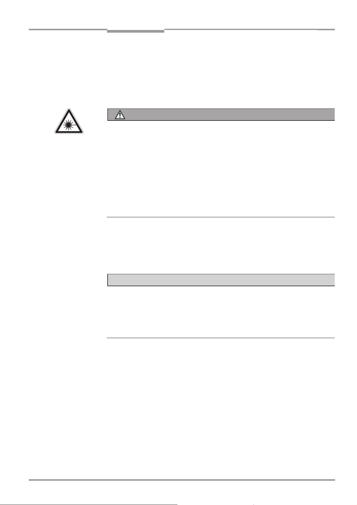
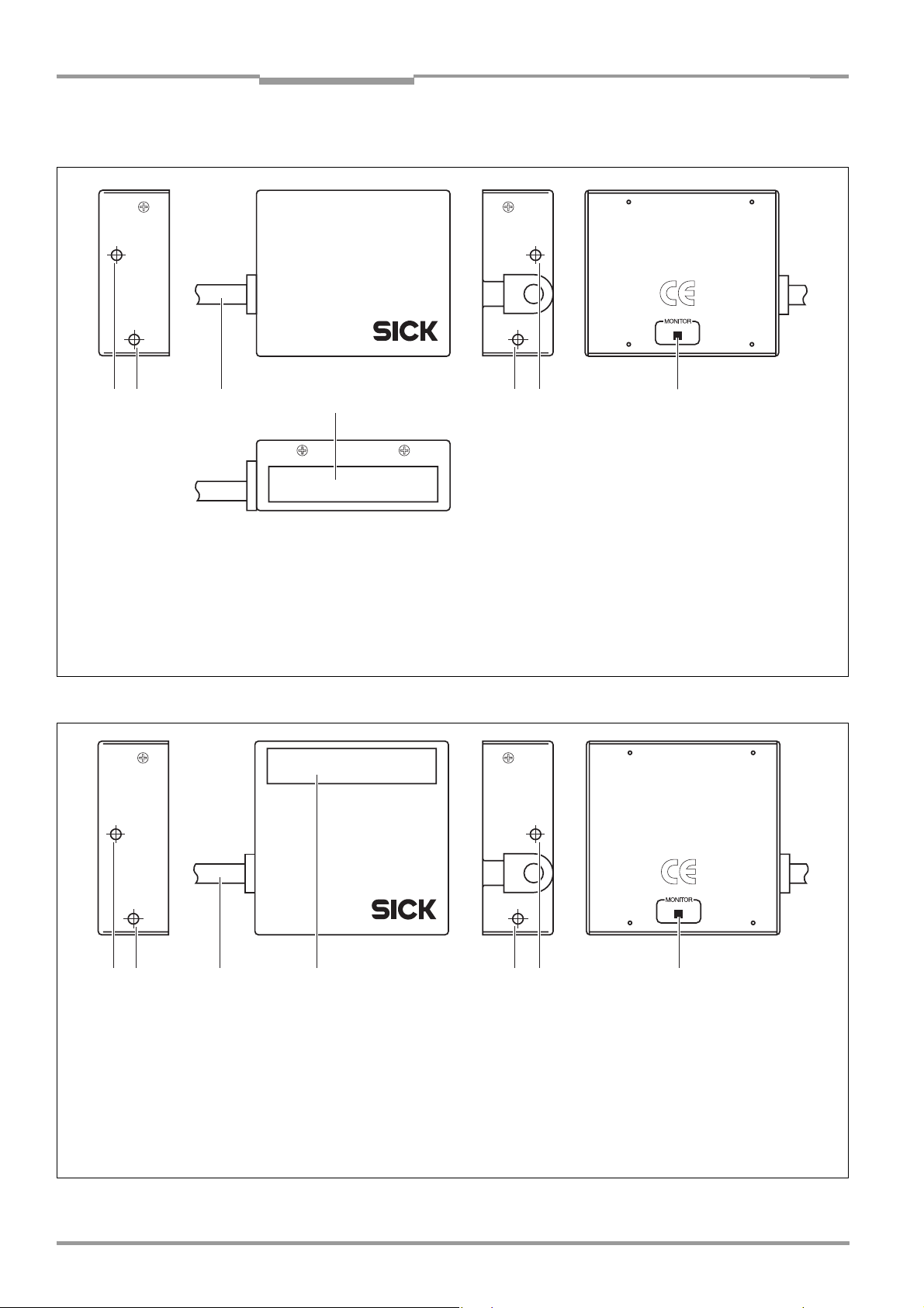
3.1.1 View of device
!! " § !!
Legend:
! Threaded hole M3, 2.5 mm deep
" Connection cable
§ Reading window
$ LED (status display)
Fig. 3-1: Design of the CLP100 with front end reading window
$
!! " § !! $
Legend:
! Threaded hole M3, 2.5 mm deep
" Connection cable
§ Reading window
$ LED (status display)
Fig. 3-2: Design of the CLP100 with side reading window
12 © SICK AG · Division Auto Ident · Germany · All rights reserved 8008912/R289/2008-11-28
Page 13

Operating Instructions Chapter 3
CLP100 Bar Code Reader
Product description
3.1.2 Scope of delivery
Delivery of the CLP100 includes the following components:
No. Component Comment
1 CLP100 bar code reader Type depends on version, see Table 3-2
1 Notes on device with electrical connection dia-
gram and quick start as primary information
1 CD-ROM "Manuals & Software Bar Code Scan-
ners"
CLP100 Operating Instructions in printed
form, in German and/or English
Table 3-1: CLP100 delivery
Included in the device packing of the
CLP100
Included in the device packing of the
CLP100
Optional, depending on the number of
issues explicitly ordered upon purchase
3.1.3 Contents of the CD-ROM (no. 2029112)
• CLP Setup: Configuration software for standard PC (Windows
TM
) with integrated
online help system CLP Setup Help (HTML files)
• CLP100 operating instructions: PDF version in German and English as well as further
publications of other SICK devices (connection modules, bar code scanners)
• Adobe Reader: Freely available PC software for displaying PDF files
Important All current versions of publications and programs on the CD-ROM can also be downloaded
at www.sick.com.
3.1.4 Variants
At present the CLP100 is available in the following variants:
Device Order no. Reading window Connection
CLP100-0010 1018331 Front 9-pin D-Sub plug
CLP100-2010 1018332 Side 9-pin D-Sub plug
CLP100-0110 1018333 Front Open cable end
CLP100-2110 1018334 Side Open cable end
Table 3-2: Variants of the CLP100
3.1.5 System requirements
The following are required to start-up and operate the CLP100:
• A supply power pack with a stabilised output voltage of 5 V DC ± 5 % in accordance with
IEC 60364-4-41 (functional extra-low voltage) and at least 2 W power output
• In the case of external reading pulsing via the "Sensor" switching input: A suitable sen-
sor for signaling an object with bar code, for example, a photoelectric reflex switch
• A PC as followed:
– Min. 80486, 66 MHz, 16 MB RAM, CD drive, a serial port (COM x), mouse
(recommended), colour screen (resolution min. 800 x 600 pixel)
– Operating system Windows 95
Windows XP
TM
.
TM
/98TM, Windows NTTM, Windows 2000TM or
– Free space available on the hard disk: approx. 6.5 MB
• An RS 232 data connection cable (null modem, TxD and RxD transposed)
• In order to install the CLP Setup configuration software and to use the CLP Setup Help
online help system an HTML browser, for example, Internet Explorer
TM
.
8008912/R289/2008-11-28 © SICK AG · Division Auto Ident · Germany · All rights reserved 13
Page 14

Chapter 3 Operating Instructions
Product description
CLP100 Bar Code Reader
3.2 Product features and functions (overview)
Feature Characteristic
High-performance bar code reader • Optical system with CCD line and integrated LED illumination
• Fixed focus
• Front reading window or side reading window
• Resolution 0.15 to 1.0 mm (5.9 mil to 39.5 mil), reading range (DOF) see Fig. 9-1, Page 44
• Scanning/decoding frequency 500 Hz
Safety and user-friendly features • Robust, compact metal housing, CE certification
• LED class 1
• Automatic self-test on startup
• Low power consumption
Easy configuration • Configuration (online/offline) via CLP Setup configuration software with integrated help
system
• Configuration alternatively with simple command strings, also for use with special devices
• Two status LEDs
Operating modes • Reading mode
• Diagnostic mode
• Adjusting mode
• Online test mode
Reading pulse • External reading pulse, via switching input(s) or serial data interface (command)
Bar code evaluation • All standard bar code types
• Max. 10 codes per reading pulse
• Code length max. 32 digits (depends on number of codes per reading pulse)
• Code comparison (one matchcode)
Data communication • Host interface: variable output format for reading result
• Auxiliary interface (auxiliary data interface): same output format as on host interface
Electrical interfaces • Host interface (RS 232), variable data transfer rate and protocol
• Auxiliary interface (RS 232 TTL), same data transfer rate and protocol as on host interface
• One digital switching input for external reading pulse
• One digital switching output for signaling the reading status
Connection technology (design) • Data and switching interfaces as well as power supply:
– Cable with 9-pin D Sub plug or
– Cable with open end
Table 3-3: Overview of the product features and functions
14 © SICK AG · Division Auto Ident · Germany · All rights reserved 8008912/R289/2008-11-28
Page 15
Operating Instructions Chapter 3
CLP100 Bar Code Reader
Product description
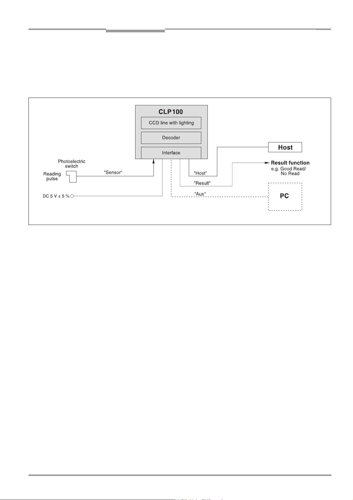
3.3 Working method of the device
The CCD bar code reader CLP100 detects bar codes in an illuminated scan field (scan line)
and decodes the bar codes. The CLP100 transmits this data via the serial host interface to
a host/PC for further processing. Refer to Fig. 3-3 for an overview of the functionality of the
CLP100.
Fig. 3-3: Function of the CLP100
--- Cable if required
The CLP100 derives useful data for diagnostics from the reading processes. The quality of
the reading data can be checked in the diagnosis mode.
The CLP100 requires suitable pulsing (triggering) in order to start a reading process when
there is an object in the reading area. This results in a time window for the reading process
being opened in the CLP100. Triggering is carried out either with an external sensor or with
a command string via the host interface. Both options are active in the default setting.
The switching input ("Sensor" input) informs the CLP100 when it must start a reading process. The switching output ("Result" output) can have result functions assigned to them and
triggers external devices such as, for example, a PLC input.
3.4 Display and operating elements
The CLP100 is operated or configured via the host interface by using the CLP Setup
PC software or with command strings. The CLP100 is adapted to various applications by
means of parameterization. The CLP Setup software is used, for example, to carry out the
following settings:
• Configuration of the code types to be read
• Read, evaluation and output properties
• Communication parameters of the host interface
• Structure of the data output strings of the host interface
• Function of the auxiliary interface (terminal interface)
Chapter 10.2, Page 46 describes the installation and handling of the CLP Setup software.
The procedure for configuring the CLP100 with the software is explained in Chapter 6.4,
Page 30.
8008912/R289/2008-11-28 © SICK AG · Division Auto Ident · Germany · All rights reserved 15
Page 16

Chapter 3 Operating Instructions
Product description
CLP100 Bar Code Reader
An LED status display ("Monitor") with two LEDs (red and green) on the rear of the CLP100
indicates the current operating state of the device. The meaning of the display for the respective operating mode is shown in Table 3-4. The display can be parameterized differently in some operating modes. The table lists all the possible meanings.
:
Operating mode Display Function
Start Green/red • Light up during the switching on phase if the self-test is suc-
cessful
• Extinguish when changing to the read standby state
Reading mode Green/red • Light up when the signal for reading is given, until the begin-
ning of the next reading cycle
Green • Lights up after successful reading ("Good Read")
Red • Extinguishes after successful reading ("Good Read")
Adjusting mode Green • Extinguishes after unsuccessful reading ("No Read")
Red • Lights up after unsuccessful reading ("No Read")
Matchcode operation Green/red • Extinguish, when there was no signal for reading and there is
no read result
Red • Lights up at "No Read" or "Read & No Match"
Green • Lights up at "Read & Match"
Table 3-4: Meaning of the LEDs
or in accordance with the parameterization
• Lights up at "No Read" or "Read & Match"
or in accordance with the parameterization
• Lights up at "Read & No Match"
16 © SICK AG · Division Auto Ident · Germany · All rights reserved 8008912/R289/2008-11-28
Page 17

Operating Instructions Chapter 4
CLP100 Bar Code Reader
Installation
4 Installation
This chapter describes the installation sequences for the CLP100.
4.1 Installation sequence
The typical installation sequences are listed below:
• Select the installation site for the CLP100
• Connect the power supply
• Align the CLP100 to the bar code
• Install the CLP100
• Adjust the CLP100
• Install the external sensor for the reading pulse
NOTICE
Claims under the warranty rendered void!
Do not open the housing of the CLP100. If the device is opened, the SICK AG warranty shall
not apply.
4.2 Preparations for installation
The following general requirements should be observed for installation:
• Typical space requirement: application-specific and type-dependent (reading range,
orientation of reading window)
• Unobstructed view of the objects for the CLP100
• Stable installation holder with sufficient load capacity and dimensions suited to the
CLP100 (see Chapter 9.3 Dimensional drawings, Page 45)
• Shock absorbent and vibration free attachment
The following tools and resources are required for installation:
• 2 screws M3 for fixing the CLP100 to the installation site,
Screw length depends on the wall thickness of the base.
Screws may not be screwed more than 2.5 mm (0.1 in) into the CLP100
• Tool
• Measuring tape
• Angulometer
4.2.1 Laying out the components to be installed ready
• CLP100 bar code reader
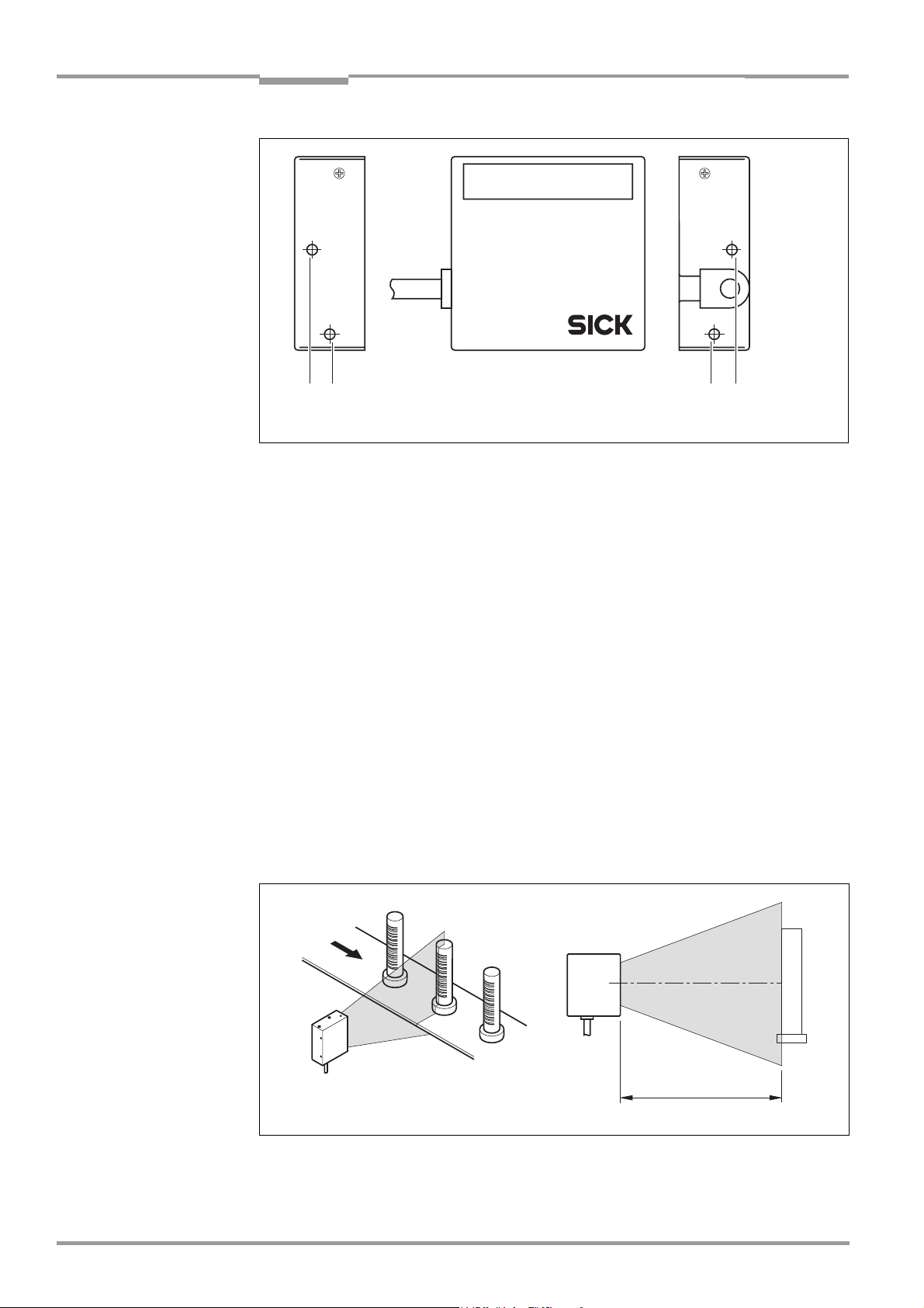
4.2.2 Threaded holes
The CLP100 is fastened by means of two threaded holes (M3) to the top or bottom of the
device (Fig. 4-1, Page 18). The complete housing dimensions are shown in Chapter 9.3 Di-
mensional drawings, Page 45.
8008912/R289/2008-11-28 © SICK AG · Division Auto Ident · Germany · All rights reserved 17
Page 18
Chapter 4 Operating Instructions
Installation
CLP100 Bar Code Reader
!! !!
Fig. 4-1: Position of the threaded holes !at CLP100
4.3 Installation site
The following aspects are relevant for the selection of the installation location:
• Reading distance to the code/field of view dimensions
• Angle alignment of the CLP100
• Avoiding surface reflections
When selecting the installation site take the distance between the CLP100 and the host.
4.3.1 Distance between the CLP100 and the host
The maximum distance between the CLP100 and the host when extension cables are used
amounts to 12 m (39.37 ft) (host interface RS 232).
4.3.2 Distance between the CLP100 and the bar code/field of view dimensions
The distance a between the reading window of the CLP100 and the bar code must amount
to 20 to 70 mm (0.79 to 2.76 in) depending on the width of the bar code (see Fig. 4-2).
Chapter 9.2 Reading field diagram, Page 44 shows the width of the reading area of the
CLP100 in relation to the reading distance for various resolutions (module widths).
a
Fig. 4-2: Reading distance to the object
18 © SICK AG · Division Auto Ident · Germany · All rights reserved 8008912/R289/2008-11-28
Page 19

Operating Instructions Chapter 4
CLP100 Bar Code Reader
Installation
Angle alignment of the CLP100
The angle between the scan line and bar code is selected, so that a good reading is possible. The optimum alignment of the CLP100 is reached at an angle of 90° between the scan
line and the bar code bars (see Fig. 4-3). Possible reading angles which can arise between
the scan line and the bar code bars must be taken into consideration (see Fig. 4-4 and
Table 4-1).
Fig. 4-3: 90° angle between the scan line and the bar code bars
Fig. 4-4: Reading angle occurring between the scan line and the bar code bars
Angle Limit
Tilt α 0° ± 2°
Pitch β 0° ± 5°
Skew γ 10° ± 5°
Table 4-1: Permissible angle occurring between the scan line and the bar code bars
8008912/R289/2008-11-28 © SICK AG · Division Auto Ident · Germany · All rights reserved 19
Page 20

Chapter 4 Operating Instructions
Installation
CLP100 Bar Code Reader
Important If the light of the scan line falls exactly vertically on the surface of the bar code, disturbing
reflections can occur when the reflected light is received. In order to avoid this effect the
CLP100 must be installed so that the emitted light is tilted relative to the perpendicular (see
Fig. 4-5).
Front end reading window Side reading window
10°
10°
Bar code
Bar code
15
Reading
Distance
Reading
Distance
Fig. 4-5: Angle between the emitted light and the bar code (tilted to the perpendicular)
8
20 © SICK AG · Division Auto Ident · Germany · All rights reserved 8008912/R289/2008-11-28
Page 21

Operating Instructions Chapter 4
CLP100 Bar Code Reader
Installation
4.4 Installation and adjustment of the device
4.4.1 Installing the CLP100
1. Align the CLP100 so that the angle between the scan line and the bar code bars
amounts to 90°. Take any possible reading angle occurring into consideration (see
Fig. 4-4, Page 19).
2. In order to avoid disturbing reflections align the CLP100 so that the emitted light im-
pacts on the bar code at an angle of 100° (see Fig. 4-5, Page 20 and Fig. 4-6).
NOTICE
Damage to the device!
The screws may not be screwed more than 2.5 mm (0.1 in) into the CLP100. Longer screws
may damage the device.
¾ Use screws with a suitable length.
3. Screw the screws through the base to which the CLP100 is fastened into the threaded
hole.
4. Tighten the screws slightly.
5. Adjust the CLP100 as described below.
ab
100°
Fig. 4-6: Adjustment of the CLP100 in order to avoid reflections;
a: With front end reading window, b: With side reading window
4.4.2 Adjusting the CLP100
The adjusting operating mode supports the adjustment of the CLP100. In this operating
mode the green LED extinguishes if the reading process fails ("No Read"). If the green LED
does not light up, the CLP100 cannot read the bar code. If the green LED flickers, the
CLP100 can only read the bar code badly. If the green LED shows steady light, the CLP100
is aligned optimally. The scanning frequency in adjusting mode amounts to 500 Hz.
1. Connect the CLP100 to the supply voltage and switch on the supply voltage.
2. Connect the CLP100 to the PC.
3. Start the CLP Setup configuration software (see Chapter 10.2, Page 46).
4. In the CLP Setup select the D
5. Click in the O
6. Click in the LED
7. Carry out the download to the CLP100 (see Chapter 6.4.1, Page 31).
PERATING MODE field and select ADJUSTING MODE.
DISPLAY field and select NO READ/GOOD READ.
EVICE CONFIGURATION tab card.
100°
8008912/R289/2008-11-28 © SICK AG · Division Auto Ident · Germany · All rights reserved 21
Page 22

Chapter 4 Operating Instructions
Installation
CLP100 Bar Code Reader
8. Guide objects with bar codes realistically into the reading area of the CLP100. Ensure
that the permitted reading angle is not exceeded.
9. Start the reading pulse: Cover the optical path of the sensor or make connection (see
Chapter 4.5, Page 22).
10. Align the CLP100 so that the green LED lights up steadily as far as possible (reading
result "Good Read").
11. Tighten the screws.
The CLP100 is aligned optimally to the bar code.
4.5 Installing the reading-pulse sensor
If the CLP100 is triggered via an external sensor, the sensor and a reflector have to be installed near the CLP100. Fig. 4-7 shows an example of the installation site of the sensor.
a
b
Fig. 4-7: Installation site for the reading-pulse sensor and the reflector (b smaller than a)
1. Install the reading-pulse sensor at the installation site.
2. Connect the reading-pulse sensor to the CLP100 (see Chapter 5.4.4, Page 27).
3. Call up the CLP Setup and check the read result with the terminal emulator (see
Chapter 6.4, Page 30).
4. Check whether the reading process of the CLP100 is synchronized with the incoming
objects.
4.6 Disassembling the device
1. Switch off the supply voltage.
2. Disconnect the cable connection.
3. Screw off the CLP100.
4. Dispose of the CLP100 ecologically friendly (see Chapter 7.4, Page 39)
22 © SICK AG · Division Auto Ident · Germany · All rights reserved 8008912/R289/2008-11-28
Page 23

Operating Instructions Chapter 5
CLP100 Bar Code Reader
Electrical installation
5 Electrical installation
5.1 Overview of installation sequences
Important Electrical installation should only be carried out by qualified staff.
The following list provides an overview of a typical installation sequence:
• Connecting the supply voltage
• Wiring the host interface (Connecting the PC)
• Wiring the "Sensor" switching input
• Wiring the "Result" switching output
Once electrical installation has been completed, the CLP100 is started up and configured
(see Chapter 6 Startup and configuration, Page 29).
5.2 Planning the electrical installation
The following general requirements should be observed for the electrical installation:
• Supply voltage 5 V DC
IEC 60364-4-41). The power supply unit must output a continuous output of 2 W and
be provided by the customer using e.g. a supply power pack.
• With external reading pulsing: Suitable reading pulse sensor (start/stop), e.g. photo-
electric reflex switch, for registering an object in the field of view
• Host computer with RS RS 232 data interface for further processing the reading data
± 5 % (functional extra-low voltage in accordance with
The following toots and resources are required for electrical installation:
• Tool
• Digital measuring device (current/voltage measurement)
8008912/R289/2008-11-28 © SICK AG · Division Auto Ident · Germany · All rights reserved 23
Page 24

Chapter 5 Operating Instructions
Electrical installation
CLP100 Bar Code Reader
5.3 Electrical connections and cables
The electrical connection of the CLP100 is carried out either via a 9-pin D-Sub cable plug or
the open cable end. The cable length is 0.9 m (2.95 ft).
5.3.1 Pin assignment of the connection plug or wire colors of the cable end
5
1
6
9
Pin Signal
1 Sensor
2 RxD (Host)
3 TxD (Host)
4 Result "GO/NG"
5 GND
6 Not assigned
7 RxD (Terminal), TTL
8 TxD (Terminal), TTL
9 +5 V
Table 5-1: Pin assignment of the D Sub plug
Wire color Signal
Pink Sensor
Brown RxD (Host)
Gray TxD (Host)
White Result "GO/NG"
Black GND
Yellow RxD (Terminal), TTL
Orange TxD (Terminal), TTL
Red +5 V
Blue RTS
Green CTS
Table 5-2: Assignment of the wire colors of the open cable end
24 © SICK AG · Division Auto Ident · Germany · All rights reserved 8008912/R289/2008-11-28
Page 25

Operating Instructions Chapter 5
CLP100 Bar Code Reader
Electrical installation
5.4 Carry out the electrical installation
NOTICE
Claims under the warranty rendered void!
Do not open the housing of the CLP100. If the device is opened, the SICK AG warranty shall
not apply.
• Connect or disconnect current linkages only under de-energised conditions.
• Wire cross sections and their correct protection have to be selected and implemented
according to valid engineering standards.
• For data connection use only shielded data cables (twisted pair).
• In order to avoid interferences, do not install data cable parallel to the power- supply
and motor cables over long distances (for example in cable ducts).
• Lay all cables so th a t t h ere is no poss i b i lity of people trip p i n g over them and s o t hat they
are protected against damage.
5.4.1 Supply voltage
For operation the CLP100 requires a supply voltage of 5 V DC
± 5 % in accordance with
IEC 60364-4-41 (functional extra-low voltage). The functional extra-low voltage can be generated by a power supply unit using a safety transformer . The power supply unit must output a continuous output of 2 W.
Important The output circuit of the power supply unit must be electrically insulated from the input
circuit. This is usually created by means of a safety transformer in accordance with
IEC 742.
To ensure that the incoming supply cables are protected against short-circuits/overloads,
the wire cross-sections must be dimensioned and protected in accordance with valid standards.
Connecting the supply voltage:
¾ Connect the supply voltage to Pin 5 and Pin 9 of the 9-pin D Sub plug (see Table 5-1,
Page 24) respectively to the wires of the open cable end (see Table 5-2, Page 24).
5.4.2 Wiring the host interface (Connecting the PC)
The CLP100 is operated and configured with the CLP Setup software. For this purpose it
must be connected temporarily to the PC via the host interface.
The host interface of the CLP100 is an RS 232 interface.
For the pin assignment refer to Table 5-1, Page 24 or Table 5-2, Page 24. Table 5-3 shows
the recommended maximum cable length as a function of the data transmission rate.
.
Interface type Transmission rate Max. distance to the host
RS 232 Up to 19,200 Bd 12 m (39.37 ft)
Table 5-3: Maximum cable length between the CLP100 and the host computer
When the PC is connected, the communications parameters are set as described in
Chapter 6.4.1 Transferring the parameter set between the CLP Setup and CLP100,
Page 31.
8008912/R289/2008-11-28 © SICK AG · Division Auto Ident · Germany · All rights reserved 25
Page 26

Chapter 5 Operating Instructions
Electrical installation
CLP100 Bar Code Reader
Fig. 5-1 shows the wiring of the host interface.
*) 9-pin internal D-Sub plug to PC
Fig. 5-1: Wiring the host interface (RS 232)
NOTICE
Damage to the interface module in the CLP100!
Electronic components can be damaged if the host interface is wired incorrectly.
¾ Wire the host interface correctly in accordance with Fig. 5-1.
¾ Check the wiring before switching on the CLP100.
¾ Connect the host interface of the CLP100 EMC-compatibly to the host by means of
shielded cables. Observe the maximum cable lengths (see Table 5-3, Page 25).
Recommendation ¾ Connect the shielding at one end.
1. Switch off the PC and the supply voltage of the CLP100.
2. Connect the desired port "COM x" of the PC to the CLP100. To this purpose use an
RS-232 data connection cable (null modem, RxD and TxD transposed).
3. Switch on the PC and the supply voltage of the CLP100.
4. Set the communication parameters of the PC (see Chapter 10.2.3, Page 48).
In the default setting the CLP100 communicates via the RS 232 interface with the host
using the values listed in Table 5-4.
Parameter Host interface value Aux interface value
Data transmission rate 9,600 Bd 9,600 Bd
Data bit 8 8
Parity None None
Stop bit 1 1
Protocol SICK:
Sending start characters: STX
Sending stop characters: ETX
Repeat request: None
Timeout: 50 ms
SICK:
Sending start characters: STX
Sending stop characters: ETX
Repeat request: None
Timeout: 50 ms
Table 5-4: Communication parameters of the host interface (default setting)
26 © SICK AG · Division Auto Ident · Germany · All rights reserved 8008912/R289/2008-11-28
Page 27

Operating Instructions Chapter 5
CLP100 Bar Code Reader
Electrical installation
5.4.3 Wiring the auxiliary (terminal) interface
As an alternative the PC may be connected to the Aux interface which operates parallel to
the host interface with the same communication parameter values. The Aux interface can
be use e.g. to monitor the data traffic on the host interface.
Fig. 5-2 shows the wiring of the Aux interface.
Important The terminal interface is a TTL level interface.
73 *
82 *
55 *
*) 9-pin internal D-Sub plug to PC
Fig. 5-2: Wiring the Aux interface (RS 232 TTL)
5.4.4 Wiring the "Sensor" switching input
If a reading process is to be triggered via an external sensor, connect the sensor to the "Sensor" switching input. This triggering type is selected as the default setting of the CLP100.
Fig. 5-3 shows the wiring of the "Sensor" switching input. Table 5-5 lists the characteristic
data of this switching input.
Fig. 5-3: Wiring of the "Sensor" switching input
¾ Connect the sensor as shown in Fig. 5-3.
Switching behaviour Connecting GND to the input starts the read port of the CLP100 (low)
Properties Not electrically separated
Electrical values Low (Reading gate active):
0 V ≤ V
≤ 0.8 V
S
I ≤ 1.5 V µA
Table 5-5: Characteristic data of the "Sensor" switching input
High (Reading gate inactive):
2.4 V ≤ VS ≤ 5 V
I ≤ 1.5 V µA
TIP The D
EVICE CONFIGURATION tab card of the CLP Setup software can be used to modify the
response time of the "Sensor" input (debouncing).
8008912/R289/2008-11-28 © SICK AG · Division Auto Ident · Germany · All rights reserved 27
Page 28

Chapter 5 Operating Instructions
Electrical installation
CLP100 Bar Code Reader
5.4.5 Wiring the "Result" switching output
The switching output can have various result functions assigned to it. If the corresponding
event occurs during a reading process, the switching output becomes live for the selected
pulse duration. Fig. 5-4 shows the wiring of the "Result" switching output. Table 5-6 lists the
characteristic data of the switching output.
Fig. 5-4: Wiring of the "Result" switching output (NPN)
¾ Wire the switching output as described in Figure 5-4.
Switching behaviour NPN switching against GND
Properties Not electrically separated
Electrical values V
Table 5-6: Characteristic data of the "Result" switching output
= 5 V ≤ V ≤ 30 V
out
I
= ≤ 50 mA
out
Recommendation ¾ In order to check the switching functions wire the switching output to a load and meas-
ure the voltage with a high-voltage digital voltmeter. This avoids the display of incorrect
voltage values and switching states.
TIP The D
EVICE CONFIGURATION tab card of the CLP Setup software can be used to modify the func-
tion assignment, the pulse duration and the output instant of the signal.
28 © SICK AG · Division Auto Ident · Germany · All rights reserved 8008912/R289/2008-11-28
Page 29

Operating Instructions Chapter 6
CLP100 Bar Code Reader
Startup and configuration
6 Startup and configuration
Startup, adjustment, configuration and diagnosis are carried out via the CLP Setup configuration software. In normal reading operation the CLP100 operates fully automated.
6.1 Overview ot the startup procedure
• Startup of the CLP100 with the default setting set by factory (Quick-Start).
• Installing the CLP Setup software (Chapter 10.2, Page 46).
• Connecting the PC to the CLP100 (Chapter 5.4.2, Page 25).
• In order for optimising the functionality of the CLP100, adjusting the CLP100 and con-
figuring the CLP100 for the application.
• Checking correct functioning of CLP100 in automatic reading operation.
6.2 Quick-Start
1. Carry out the electrical installation in accordance with Chapter 5, Page 23. A PC does
not have to be connected if the CLP100 is operated with the default setting.
2. Switch on the supply voltage.
The LEDs of the CLP100 light up and are extinguished after the self-test has been completed successfully.
3. Present the bar code sample from Fig. 6-1 to the CLP100 at a distance of approx.
35 mm.
4. Start the reading pulse: Cover the optical path of the sensor (close the switch).
Both LEDs on the rear light up.
5. End the reading pulse: Unmask the optical path of the sensor (open the switch).
If the reading has been successful, the red LED is extinguished, the green LED lights up.
The CLP100 is ready to operate with the default setting of our works.
The CLP100 can be switched off without the configuration data being lost, since no changes
were carried out to the parameter set.
0123412345
Fig. 6-1: Bar code sample (code 39, 0.35 mm (13.8 mil)), printing ratio 2:1)
The default setting shows Table 6-1, Page 35.
8008912/R289/2008-11-28 © SICK AG · Division Auto Ident · Germany · All rights reserved 29
Page 30

Chapter 6 Operating Instructions
Startup and configuration
CLP100 Bar Code Reader
6.3 Operating modes and output of the read result
When configuring the CLP100, it is possible to choose between the following operating
modes:
• Reading mode
• Diagnostic mode
• Adjusting mode
• On-line test mode
In reading mode the CLP100 detects the presented bar codes and emits the read result at
the end of the reading pulse parallel via the host and aux interface.
In diagnosis mode the quality of the bar code readings is judged. These are brought statistically into the read field of the CLP100 (no transport movement). The output is emitted via
the host and aux interface. For details on the diagnosis mode refer to Chapter 6.4.8,
Page 33.
In adjusting mode the CLP100 is adjusted to the bar code (see Chapter 4.4.2, Page 21).
In the on-line test mode the CLP100 emits the read result only via the aux interface and not
via the host interface.
When outputting the read result, it is possible to choose between the normal reading function and the code comparison function (matchcode). The matchcode function allows the
comparison of the read bar codes with a code which is entered at the CLP100. It is possible
to select between complete or partial matching of the codes.
6.4 Configuration
The CLP Setup configuration software or command strings optimise the CLP100 to reading
conditions on site. Starting point for this is the factory default setting which can be adjusted
to optimise the CLP100. The CLP Setup configuration software is used to create an application-specific parameter set which can be loaded permanently into the CLP100 and saved/
archived as a configuration file (slp file) on the PC.
CLP100
Parameter set in the
main memory
Permanently saved
parameter set
Factory default setting
Download
Upload
RAM
PROM
ROM
PC with CLP Setup
configuration software
Opened configuration file
with current parameter set
(after upload)
RAM
Saved configuration file
(*.slp) with archived parameter set
Data base
(hard drive)
Fig. 6-2: Configuration with CLP Setup and storage of the parameter set
To this purpose a PC has to be connected and the CLP Setup has to be installed.
30 © SICK AG · Division Auto Ident · Germany · All rights reserved 8008912/R289/2008-11-28
Page 31

Operating Instructions Chapter 6
CLP100 Bar Code Reader
Startup and configuration
6.4.1 Transferring the parameter set between the CLP Setup and CLP100
In order to edit the current parameter set of the CLP100 it must first be copied from the
CLP100 to the CLP Setup. This process is designated as uploading.
Changes to the parameter set carried out in the CLP Setup are not effective until they have
been transferred to the CLP100. CLP Setup always copies the complete parameter set. Saving the parameters to the CLP100 is designated as downloading.
Uploading the parameter set from the CLP100
¾ Click on in the CLP Setup toolbar.
CLP Setup copies the parameter set last saved in the CLP100 from the CLP100 into its
database and displays its values in the tab cards.
If the CLP Setup software does not recognize the loaded parameters during uploading, a
warning is emited. Unknown parameters can be edited in the terminal emulator under observance of the conventions for command strings. These parameters are also taken into
consideration when the parameter set is saved.
Downloading the parameter set to the CLP100
¾ Click on in the CLP Setup toolbar.
The new parameter set is saved in the CLP100.
Saving the parameter set in the CLP Setup
1. Select the S
AVE AS menu item in the FILE menu bar in order to save the modified param-
eter set as the new configuration file in the CLP Setup or to overwrite an existing file.
The S
AVE CLP FILE dialog box is opened.
2. Enter the path and file name in the dialog box (extension of the file name: "*.slp") and
click on OK.
The new parameter set is saved in the CLP Setup.
6.4.2 Parameterize the CLP100 with command strings
The CLP100 can be parameterized for example by means of the terminal emulator by entering command strings. Parameters which are unknown to the CLP Setup can also be used.
The command language of the CLP100 accesses the command interpreter of the device directly. Fig. 6-3, Page 32 shows a view of the terminal emulator. A0 is entered as an example
in the framed text field for entering commands. This input is repeated in the large output
window. For a full description of the command language refer to Table 10-4, Page 53.
1. Click on in the CLP Setup toolbar.
The terminal emulator window opens.
2. Enter the command in the framed text field and press the Return key.
The command is transmitted to the CLP100.
Important The CLP100 does not transmit an answer, but reacts immediately to the command.
8008912/R289/2008-11-28 © SICK AG · Division Auto Ident · Germany · All rights reserved 31
Page 32

Chapter 6 Operating Instructions
Startup and configuration
CLP100 Bar Code Reader
Fig. 6-3: Terminal emulator with input of a command string
6.4.3 Selecting reading mode
After being switched on the CLP100 carries out a self-test and then changes over to the
reading mode (default setting). Reading mode can be selected as follows if the CLP100 is
in another operating mode:
1. In the CLP Setup select the D
2. Click in the O
PERATING MODE field and select READING MODE.
3. Carry out the download to CLP100.
The CLP100 is in reading mode.
6.4.4 Adjusting the reading pulse
In the CLP100 default setting the reading pulse (trigger) is supplied by an external sensor.
Debouncing of the sensor and the type of reading pulse end (through a time window or a
sensor signal) can be set by means of the CLP Setup software.
1. In the CLP Setup select the D
2. Select the settings in the R
3. Carry out the download to CLP100.
6.4.5 Triggering the reading pulse
EVICE CONFIGURATION tab card.
EVICE CONFIGURATION tab card.
EADING PULSE or READING PULSE END field.
In its default setting the CLP100 receives the reading pulse (trigger) via an external sensor
or a command string (software trigger). For test purposes, the reading pulse can also be triggered directly via the terminal emulator.
1. Click on in the CLP Setup toolbar.
The terminal emulator window opens. The CLP100 is in reading mode.
32 © SICK AG · Division Auto Ident · Germany · All rights reserved 8008912/R289/2008-11-28
Page 33

Operating Instructions Chapter 6
CLP100 Bar Code Reader
Startup and configuration
2. Click on START READING.
3. Present the bar code.
4. Click on S
TOP READING.
The CLP100 outputs the read result in the window of the terminal emulator.
6.4.6 Setting the structure of the read result
In its default setting the CLP100 sends the data contents of the bar code to the host as the
read result. In the default setting this data string is STX-/ETX-framed.
The structure of the data string can be selected by means of the H
CONFIGURATION tab cards.
1. In the CLP Setup select the R
2. Click in the S
3. Select the H
4. Click in the S
END PREFIX list box and select a prefix from the list (A-Z, 1-0).
OST INTERFACE tab card.
EPARATOR list field and select a separator.
EADING CONFIGURATION tab card.
OST INTERFACE and READING
5. Carry out the download to CLP100.
The CLP100 operates with the new settings.
6.4.7 Setting the matchcode function
The matchcode function allows the comparison of the read bar codes with a code which is
entered manually at the CLP100 or trained in automatically (matchcode).
1. In the CLP Setup select the D
2. Click in the A
CTIVE box in the COMPARE CODE field.
3. Enter the code which is to be used for comparison in the M
4. If only a part of the code has to agree, enter the partial code in the P
OF THE MATCHCODE text field, and complete the field with question marks or @ characters.
5. Selection the function of the switching output in the S
SON field.
EVICE CONFIGURATION tab card.
ATCHCODE text field.
ARTIAL COMPARISON
WITCHING OUTPUT AT CODE COMPARI-
6. Carry out the download to CLP100.
The CLP100 outputs a result either at agreement of the read codes with the matchcode
or at non-agreement.
6.4.8 Setting the diagnosis mode
In diagnosis mode the quality of the bar code readings is judged. These are brought statistically into the read field of the CLP100 (no transport movement). The CLP100 carries out
100 readings after the reading pulse and evaluates them.
The data string in the diagnosis mode is STX-/ETX-framed. The data string contains the bar
code information (data) at the first place, followed by a slash and a three-digit identifier. The
data string is followed by the combination of slash and identifier repeated thrice (a total of
four identifiers separated by slashes):
<STX>Data/www/xxx/yyy/zzz<ETX>.
The maximum value of an identifier is 100. If the value is lower (one- or two-digit number),
the leading blanks will be filled with spaces. If the D
ISPLAY CONTROL CODE function is activated,
a space is displayed as <SPC>. The identifiers mean:
www = Number of successful readings ("Good reads")
xxx = Number of successful decoding processes (with misinterpretations)
8008912/R289/2008-11-28 © SICK AG · Division Auto Ident · Germany · All rights reserved 33
Page 34

Chapter 6 Operating Instructions
Startup and configuration
CLP100 Bar Code Reader
yyy = Number of successful indentifications of a start or stop character (depending on
the scan direction)
zzz = Number of readings carried out (the CLP100 carries out 100 readings each in the
diagnosis mode)
Error-free reading and decoding of a bar code would thus have the following form:
<STX>Data/100/100/100/100<ETX>.
A reading with some failed decodings has, for example, the following form:
<STX>Data/<SPC>67/<SPC>67/100/100<ETX>.
If the CLP100 has only recognized the start character, it transfers a question mark instead
of the data string:
<STX>?/<SPC><SPC>0/<SPC><SPC>0/100/100<ETX>.
Fig. 6-4 shows further examples of reading results in the diagnosis mode:
Fig. 6-4: Terminal emulator with reading results of the CLP100 in diagnosis mode
The diagnosis mode can be selected directly in the terminal emulation window or set via the
tab cards:
¾ If the terminal emulator window is active: Click in the D
IAGNOSTIC MODE box and present
the bar code.
The reading process is started automatically. The CLP100 scans the bar code once per
second.
- or -
1. If the terminal emulator window is not active: In the CLP Setup select the D
URATION tab card.
2. Click in the O
PERATING MODE field and select DIAGNOSTIC MODE.
EVICE CONFIG-
3. Carry out the download to CLP100.
The CLP100 is in diagnosis mode.
34 © SICK AG · Division Auto Ident · Germany · All rights reserved 8008912/R289/2008-11-28
Page 35

Operating Instructions Chapter 6
CLP100 Bar Code Reader
Startup and configuration
4. Click on in the CLP Setup toolbar.
The terminal emulator window opens.
5. Click on S
TART READING.
6. Present the bar code.
The CLP100 outputs the read result in the window of the terminal emulator.
7. In order to return to reading mode proceed as described in Chapter 6.4.3, Page 32.
6.5 Default setting
Table 6-1 shows an overview of the default setting of our works for the CLP100. The para-
meters in the default setting are selected so that the CLP100 can be used directly for many
applications in this configuration. With the default setting no PC is required for starting up.
Parameter Default setting
Active code type Code 39
Code length Free
Multiple reading 2
Number of codes 1
Reading direction Both
Send start/stop characters Not active
Check digit None
Reading pulse generation Active low (unchangable)
Switching output Not active
Host interface RS 232 (unchangable)
Protocol Start characters STX, Stop characters ETX
Data transmission rate 9,600 Bd
Data format 8 data bits, no parity, 1 stop bit
Output instant Immediately
No Read message BR
Table 6-1: Default setting of the parameters of the CLP100
If the CLP100 is connected to a PC, the current parameters can be changed by using the
CLP Setup software. The parameter set of the default setting is saved in the CLP Setup and
in the CLP100 and can be re-activated at any time.
The complete default setting can be viewed by using the CLP Setup software and printed
out, if required:
1. In order to save the current settings: Select the S
AVE AS menu item in the FILE menu bar
and enter the file name.
2. Click on in the toolbar.
The default setting is loaded and is displayed in the tab cards.
3. Click on in the toolbar.
The F
ILE PRINT dialog box is opened.
4. Enter the comment for the header of the output and click on OK.
The dialog box for the print settings is opened.
5. Enter the settings for printing and click on OK.
CLP Setup prints out the default settings.
8008912/R289/2008-11-28 © SICK AG · Division Auto Ident · Germany · All rights reserved 35
Page 36

Chapter 6 Operating Instructions
Startup and configuration
CLP100 Bar Code Reader
6.6 Switching off the CLP100
1. If the parameter set was changed, download the parameter set to the CLP100 and save
the parameter set as a configuration file in the CLP Setup.
2. Switch off the supply voltage.
The last parameter set saved in the CLP100 remains valid.
36 © SICK AG · Division Auto Ident · Germany · All rights reserved 8008912/R289/2008-11-28
Page 37

Operating Instructions Chapter 7
CLP100 Bar Code Reader
Maintenance
7 Maintenance
7.1 Maintennance during operation
The CLP100 operates maintenance free. No maintenance is required to keep this product
in compliance with LED class 1.
NOTICE
Claims under the warranty rendered void!
Do not open the housing of the CLP100. If the device is opened, the SICK AG warranty shall
not apply.
7.2 Cleaning the CLP100
Recommendation In order to make use of the full optical reading capacity of the CLP100, the reading window
should be checked regulary (e.g. weekly) for soiling. This is especially recommended when
operating the device in harsh conditions (dust, abraison, humidity).
CAUTION
LED radiation!
The illumination of the CLP100 operates with LEDs of LED class 1. Under normal and sensible conditions, the accessible radiation of the LEDs is not hazardous.
The entire area of the reading window acts as a LED outlet aperture.
Caution – use of controls or adjustments or performance of procedures other than those
specified herein may result in hazardous radiation exposure.
¾ Never look directly into the illumination.
¾ Do not open the housing.
(Opening the housing does not deactivate the LEDs by the reading pulse.)
¾ Always observe the latest valid version of laser protection regulations.
7.2.1 Cleaning the reading window
NOTICE
Damage to the reading window!
The CLP100 reading window is made of glass.
Scratches and streaks on the reading window impair the reading performance.
¾ Use a mild detergent without scouring agents.
¾ Avoid cloths or sponges which scratch.
¾ Clean the reading window carefully.
Important Electrostatic charges cause dust particles to stick to the reading window. This effect can be
combated by using anit-static SICK synthetic cleaner (no. 5600006) in combination with a
SICK lens cloth (no. 4003353).
8008912/R289/2008-11-28 © SICK AG · Division Auto Ident · Germany · All rights reserved 37
Page 38

Chapter 7 Operating Instructions
Maintenance
CLP100 Bar Code Reader
Cleaning the reading window:
¾ Use a clean, soft brush to free the reading window.
¾ If necessary, additionally clean the reading window with a clean, damp, lint-free cloth
and a mild, anti-static window cleaning fluid.
a
Fig. 7-1: Cleaning the reading window
If the reading window is scratched or damaged (cracked, broken), it must be replaced.
Please contact the SICK Service.
7.2.2 Cleaning the housing
¾ If necessary, also clean the LEDs on the back side of the housing.
7.2.3 Cleaning further optical effective surfaces
If an external reading pulse generator with a sensor (e.g. photoelectric reflex switch) is used,
make sure to clean the relevant optical surfaces regulary (e.g. weekly). Contamination on
these surfaces can cause switching errors.
¾ In oder to prevent incorrect switching behaviour, remove soiling from the optical effec-
tive surfaces of the external sensor.
b
7.3 Replacing a CLP100
An incorrect or damaged CLP100 has to be removed and replaced with either a new or an
repaired CLP100.
NOTICE
Repairs to the CLP100 should only be carried out by qualified and authorised SICK AG
service staff.
7.3.1 Removing the CLP100
1. Switch off the power supply to the CLP100.
2. Remove the cable plug of the CLP100 respectively remove the wires when using the
variant with open cable end.
3. Mark the situation and alignment of the CLP100 on the holder or environment.
4. Remove the CLP100 from the holder.
38 © SICK AG · Division Auto Ident · Germany · All rights reserved 8008912/R289/2008-11-28
Page 39

Operating Instructions Chapter 7
CLP100 Bar Code Reader
Maintenance
7.3.2 Replacing the CLP100
1. Align and install the new or repaired CLP100.
To do so, observe any marks made previously on the holder or environment (see also
Chapter 4.4 Installation and adjustment of the device, Page 21).
2. Reconnect the cable plug of the CLP100 respectively reconnect the wires when using
the variant with open cable end.
3. Switch on the power supply to the CLP100.
The CLP100 starts with the factory default settings.
4. Establish communication to the CLP100 using the CLP Setup configuration software.
5. Transfer the configuration of the replaced device stored on the PC via download to the
new CLP100 (see Chapter 6.4.1 Transferring the parameter set between the
CLP Setup and CLP100, Page 31). The configuration can only be transferred between
identical device types.
6. Check the behaviour of the CLP100 in the reading process.
7.4 Disposal
After removal from service dispose of unusable or irreparable devices in a manner which is
not harmful to the environment. Observe the respective state regulations on waste disposal.
At present, SICK AG does not take back devices which have become unusable or irreparable.
1. Remove the CLP100 housing.
2. Remove the electronic modules and connection cable.
3. Recycle the housing.
4. Dispose of electronic modules and connection cable as hazardous waste.
8008912/R289/2008-11-28 © SICK AG · Division Auto Ident · Germany · All rights reserved 39
Page 40

Chapter 8 Operating Instructions
Troubleshooting
CLP100 Bar Code Reader
8 Troubleshooting
This chapter describes how errors at the CLP100 can be recognised and eliminated.
NOTICE
Claims under the warranty rendered void!
Do not open the housing of the CLP100. If the device is opened, the SICK AG warranty shall
not apply.
8.1 Possible errors and faults
8.1.1 Installation faults
• CLP100 aligned unfavorably to the bar code (for example, reflections).
• Reading-pulse sensor positioned incorrectly
8.1.2 Faults during the electrical installation
• Interfaces of the CLP100 wired incorrectly
8.1.3 Parameterization errors
• Functions not adapted to the local conditions, for example, communication parameters
of the host interface set incorrectly
8.1.4 Faults during operation
• Device fault (hardware/software)
40 © SICK AG · Division Auto Ident · Germany · All rights reserved 8008912/R289/2008-11-28
Page 41

Operating Instructions Chapter 8
T
CLP100 Bar Code Reader
roubleshooting
8.2 Troubleshooting table
Aids during troubleshooting:
• These operating instructions
• Multimeter for measuring voltage and current
Fault Possible cause Check Remedy
1. When the supply voltage is
applied to the CLP100:
The LEDs do not light up
(LEDs must light up for
three seconds after
voltage is applied if the
self-test is successful)
2. CLP100 cannot be started
via the external sensor,
Scan field of the CLP100
(red light) is not displayed
or
LEDs do not light up after
an executed signal for
reading
3. Green LED does not light
up after the end of the
reading pulse (reading not
successful)
Tab l e 8-1: Troublesh o oting t a ble
1.1 CLP100 without supply
voltage
1.2 CLP100 has diagnosed a
device fault during the
self-test
2.1 External sensor connected
incorrectly
2.2 Photoelectric switch not
aligned to the reflector or
Optical path covered (light
scanner or inductive
sensor is not dampened)
2.3 CLP100 does not receive
command string for
pulsing via the host
interface
3.1 No bar code in the reading
area during the reading
process
3.2 Scan field does not
contact the bar code
3.3 Reading distance
incorrect
3.4 Evaluation criteria for the
code type set incorrectly
3.5 Reading angle under
which the bar code
appears is too large
1.1 Check the supply voltage 1.1 Check the wiring and
measure the supply
voltage (DC 5 V ± 5 %)
1.2 Switch the device off and
on again. Do the LEDs
light up?
2.1 Check the wiring of the
external sensor
2.2 Check the external sensor
for functionality and a free
optical path
2.3 Check the data
connection between the
host and the CLP100.
Check the command
strings of the host
computer
3.1 Check the interval
between the reading pulse
and presence of the bar
code in the reading area
3.2 Check the adjustment. Is
the bar code in the middle
of the scan field?
3.3 Check the reading
distance
3.4 Check the code type and
code length
3.5 Check the reading angle 3.5 Readjust the CLP100
1.2 If the LEDs do not light up,
contact the SICK service
(refer to Chapter 8.3,
Page 42)
2.1 Measure the output signal
of the external sensor and
the input signal at the
CLP100 (active low)
2.2 Re-align the external
sensor
2.3 Carry out the connection
in accordance with
Chapter 5.4, Page 25 and
observe the pin
assigment. Carry out an
upload in the CLP Setup.
On the H
card set the data format,
protocol, start and stop
characters, baud rate
correctly.
Carry out the download to
the CLP100
3.1 Refer to Item 2
3.2 Readjust the CLP100
(refer to Chapter 4.4.2,
Page 21)
3.3 Set the correct reading
distance, but take the
module width into
consideration (refer to
Chapter 10.3, Page 51)
3.4 Enter correct code type in
CLP Setup. Carry out
download to CLP100
while ensuring that the
maximum reading angle is
observed (refer to Fig. 4-4,
Page 19)
OST INTERFACE tab
8008912/R289/2008-11-28 © SICK AG · Division Auto Ident · Germany · All rights reserved 41
Page 42

Chapter 8 Operating Instructions
Fault Possible cause Check Remedy
–continued–
3. Green LED does not light
up after the end of the
reading pulse (reading not
successful)
4. CLP100 does not transfer
read results after the end
of the reading pulse
Troubleshooting
CLP100 Bar Code Reader
3.6 Fault due to reflection of
the light at the bar code
3.7 Bar code quality is
insufficient
4.1 No reading pulse occurred 4.1 Do the LEDs light up after
4.2 Data connection cable
wired incorrectly
4.3 Voltage level incorrect 4.3 Check the voltage level 4.3 Correct the voltage level
4.4 Host interface
parameterized incorrectly
3.6 Check the angle 3.6 Readjust the CLP100 and
tilt it relative to the vertical
(refer to Fig. 4-5, Page 20)
3.7 Check the printing
contrast, idle zones and
print tolerances of the bar
code
the reading pulse?
4.2 Check the wiring 4.2 Carry out the wiring in
4.4 Check the data format,
protocol, start and stop
characters
3.7 Have the bar code
checked (for example by
the SICK service (refer to
Chapter 8.3, Page 42))
4.1 Refer to Item 2
accordance with the pin
assignment and the
connection scheme
4.4 Carry out an upload in the
CLP Setup. On the HOST
NTERFACE tab card set the
I
data format, protocol,
start and stop characters,
baud rate correctly.
Carry out the download to
the CLP100
Table 8-1: Troubleshooting table (contd.)
8.3 SICK support
Repairs to the CLP100 should only be carried out by qualified and authorised SICK AG
service staff.
If an error cannot be eliminated using the above measures, it is possible that the CLP100
is defective. The CLP100 cannot be repaired by the user, meaning that it is not possible to
re-estabilsh functions after a failure. However, the CLP100 can be rapidly replaced by the
user. See Chapter 7.3 Replacing a CLP100, Page 38.
If an error occurs which cannot be eliminated, please contact SICK Service:
• International: Competent SICK branch office or SICK subsidary
¾ Only return devices after consultation with the SICK Service.
NOTICE
– For telephon numbers and e-mail addresses please see the back page of these
operating instructions
– For the postal address please visit www.sick.com.
42 © SICK AG · Division Auto Ident · Germany · All rights reserved 8008912/R289/2008-11-28
Page 43

Operating Instructions Chapter 9
CLP100 Bar Code Reader
Technical data
9 Technical data
9.1 Data sheet CLP100 bar code reader
Type CLP100
Scanner design CCD bar code reader
Light source Visible red light (λ = 630 nm)
LED class Class 1 according to EN 60825-1/A2 (2001-03) and
IEC 60825-1 AMD2 (2001-01)
Artificial light compatability 0 to 100,000 lux
Scanning/Decoding frequency 500 Hz
Reading distance/Resolution 30 to 40 mm: 0.15 mm
(1.18 to 1.58 in 5.9 mil)
25 to 45 mm: 0.2 mm
(0.99 to 1.77 in 7.9 mil)
25 to 45 mm: 0.25 mm
(0.99 to 1.77 in 9.8 mil)
25 to 55 mm: 0.35 mm
(0.99 to 2.17 in 13.8 mil)
25 to 55 mm: 0.5 mm
(0.99 to 2.17 in 19.7 mil)
25 to 55 mm: 1 mm
(0.99 to 2.17 in 39.5 mil)
Reading area width 80 mm (3.15 in) (at a reading distance of 40 mm
(1.58 in))
Minimum resolution 0.15 mm (5.9 mil)
Code types All common bar codes
Number of codes per reading pulse Max. 10 codes
Code length Max. 32 digits (depends on number of codes per read-
ing pulse)
Optical indicators Status display with two LEDs (red and green)
Data interfaces 2 x (RS 232), parallel operation (transmitting/monitor-
ing)
Data transfer rate 1,200 to 19,200 Bd
Digital switching input V
Digital switching output I
Electrical connection Cable (0.9 m (2.95 ft)), with 9-pin D Sub plug or open
Supply voltage 5 V DC ± 5 % according to IEC 60364-4-41
Power consumption (reading operation) 350 mA
Power consumption (standby mode) 150 mA
Housing Metal
Enclosure rating IP 40
EMC test According to EN 61000-6-2 (2001-10-01), 61000-6-3
Weight Approx. 200 g (7.05 oz)
Temperature
(ambient service/storage)
Maximum relative humdity 30 to 85 %, non-condensing
= max. 5 V, Iin ≤ 1,5 µA
in
= max. 50 mA
out
end
(2001-10-01), 61000-6-3/A11 (2004-07-01)
0 to +40 °C / −20 to +70 °C
(+32 to 104 °F/ −4 to +158 °F)
Table 9-1: Technical specification of the CLP100
8008912/R289/2008-11-28 © SICK AG · Division Auto Ident · Germany · All rights reserved 43
Page 44

Chapter 9 Operating Instructions
Technical data
CLP100 Bar Code Reader
9.2 Reading field diagram
The reading area diagram shows the reading width as a ratio of the reading distance for various resolutions. Disturbing optical effects (distortions) which can occur when the distance
is too great are taken into account when specifying the reading width.
The module width is the narrowest bar of a bar code which is still resolved.
(in)
(1.97)
(1.58)
(1.18)
Reading field height
(0.79)
(0.39)
(-0.39)
(-0.79)
(-1.18)
(-1.58)
mm
(-1.97)
(0.39)
Resolution in mm (mil) a: 0.15 (5.9 mil)
Reading Conditions: Test Code:
Print Ratio:
Print Contrast:
Pitch/Tilt
Fig. 9-1: Reading field diagram
(0.79)
(1.18)
39
3:1
90 %
0°
(1.58)
mm
(1.97)
b: 0.2 (7.9 mil), 0.25 (9.8 mil)
c: 0.35 (13.8 mil), 0.5 (19.7 mil),
1.0 (39.5 mil)
(2.76)
(2.36)
Reading distance
(in)
44 © SICK AG · Division Auto Ident · Germany · All rights reserved 8008912/R289/2008-11-28
Page 45

Operating Instructions Chapter 9
CLP100 Bar Code Reader
Technical data
9.3 Dimensional drawings
*) Screws may not project more than
2.5 mm (0.1 in) into the CLP100
All dimensions in mm
Fig. 9-2: Dimensions of the CLP100 with front end reading window
All dimensions in mm
*) Screws may not project more than
2.5 mm (0.1 in) into the CLP100
Fig. 9-3: Dimensions of the CLP100 with side reading window
mm inch mm inch mm inch mm inch
3 0.12 7 0.28 15 0.59 24 0.95
4.5 0.18 10 0.39 16.5 0.65 47 1.85
5 0.20 11 0.43 20 0.79 55 2.17
Table 9-2: Conversion table for dimensions in the figures above (mm to inch)
8008912/R289/2008-11-28 © SICK AG · Division Auto Ident · Germany · All rights reserved 45
Page 46

Chapter 10 Operating Instructions
Appendix
CLP100 Bar Code Reader
10 Appendix
10.1 Appendix overview
• Installation and handling of the CLP Setup software
• Calculation of the number of scans
• Calculation of the code length of a bar code
• Command language for CLP100 bar code readers
• Copy of the EC Declaration of Conformity (page 1)
10.2 Installation and handling of the CLP Setup software
The scope of delivery of the CLP100 includes a CD-ROM (“Manuals & Software“) with the
CLP Setup software. A PC with the operating system Windows 95
Windows 2000
TM
or Windows XPTM as well as an HTML browser, e.g. Internet ExplorerTM is
TM
/98TM, Windows NTTM,
required in order to install and use the software. The memory requirement on the hard disk
amounts to approx. 6.5 MB for the installation of CLPSetup and CLPSetup Help.
10.2.1 Preparing the installation
1. Have the CD ROM (“Manuals & Software“) at hand.
2. Connect the PC to the host interface of the CLP100 (see Chapter 5.4.2, Page 25).
3. Switch on the supply voltage of the CLP100.
4. Switch on the PC and start Windows.
Important The following instructions describe how to install the software on Windows 95
structions may differ depending on the operating system you are using (for example, administrator rights are required to install the software on Windows NT
TM
).
10.2.2 Carrying out the installation
The installation can be carried out directly from the CD-ROM or after the software has been
saved on your local hard disk.
During the installation of CLP Setup the installation program creates a main directory with
subdirectories and the required links. CLP Setup can be removed completely from the PC
by using the Uninstaller which is automatically installed as well.
TM
. These in-
First installation
1. Shut down all the applications running in Windows.
2. Insert the CD-ROM into the CD-ROM drive.
3. If the auto run function is enabled, the start page (table of contents) of the CD-ROM is
automatically displayed in the your browser.
4. Select the S
5. Select CLP S
OFTWARE folder on top left.
ET-UP SOFTWARE in the listing.
A table with CLP100 information is displayed.
6. Select D
7. In the F
OWNLOAD under SOFTWARE FILE .
ILE DOWNLOAD dialog box select the option to install directly from the CD-ROM.
Confirm with OK.
- or -
46 © SICK AG · Division Auto Ident · Germany · All rights reserved 8008912/R289/2008-11-28
Page 47

Operating Instructions Chapter 10
CLP100 Bar Code Reader
Appendix
Select the option to save the software locally on your local hard disk and confirm with
OK.
In the F
ILE DOWNLOAD dialog box select the desired target directory on your hard disk.
The “CLPSetup.exe“ file is then saved at this location.
Select O
PEN in the dialog box to start the file.
8. The installation program starts and guides you through the installation with screen
messages. The CLP Setup software and the CLP Setup Help online help are installed.
9. Observe the the latest information on the CLP Setup given in the Readme file.
10. Click on OK to confirm the final installation message.
The CLP Setup software and the CLP Setup Help online help are installed and ready for
use.
Updating an installation
There are two possibilities of installing a new version of CLP Setup:
• Installation of the new version in addition to the old version
- or -
• Installation of the new version instead of the old version (overwriting)
Installation of the new version in addition to the old version
When the new version is installed in addition to the old version the new CLP Setup software
is installed as described under First installation. When prompted for the target directory you
have to enter a new directory. Both software versions are available parallel, but may not be
started simultaneously. The configuration files of the old version can continue to be used in
the new version.
Installation of the new version instead of the old version
When the new version is installed instead of the old one, the files of the old version have to
be removed – with the exception of the configuration files "*.slp". The "*.slp" files contain
the parameter sets of the CLP100.
The Uninstaller removes the program files. The Uninstaller can be used to remove either all
the files (with the exception of the configuration files) or only selected files. The default setting is the complete removal (the configuration files are not removed). In the case of userspecific removal the files are listed and only the selected files are removed. When selecting
files ensure that the main directory together with the "*.slp" files is not deleted.
1. Select the Uninstaller for CLP Setup in the start menu of Windows under P
ROGRAMS.
The Uninstaller starts and guides you through the removal with screen messages.
2. Select the type of removal (complete or user-specific).
3. The new version of CLP Setup is installed as described under First installation. Select
the same directory.
The new version of CLP Setup is installed. The configuration files of the old version can
continue to be used.
8008912/R289/2008-11-28 © SICK AG · Division Auto Ident · Germany · All rights reserved 47
Page 48

Chapter 10 Operating Instructions
Appendix
CLP100 Bar Code Reader
10.2.3 Starting the CLP Setup software
The CLP Setup software starts with the following default setting:
Communication COM 1, 9,600 Bd, 8 data bits, 1 stop bit, no parity
Linear measures Metric
Language English
Browser Not assigned
Directory for files "Data" (configuration files for CLP100)
Table 10-1: Default settings of CLP Setup
1. Switch on the PC and start Windows.
2. Select CLP Setup in the start menu.
The introductory dialog box is displayed after the identifier for the SICK software.
3. Click on OK.
CLP Setup checks whether a bar code reader is connected to the port "COM 1" of the
PC and whether the values of the communication parameters between the bar code
reader and the PC agree. If the values agree, CLP Setup enters C
ONNECTED in the top
right-hand of the status bar.
The software loads the internal description of the bar code reader and the default setting of the parameters from the database and displays it in the tab cards. Then the software copies the last set saved permanently in the CLP100 from the CLP100.
Afterwards this is displayed in the tab cards.
The current parameter set can be edited in the tab cards.
Help in cases of problems
If the CLP Setup displays the message N
O CONNECTION in the top right-hand of the status bar,
the software could not establish a connection to the CLP100. This can have two causes. The
CLP100 is not connected, or the communication parameters of the CLP100 and the PC do
not agree.
1. Connect the PC to the host interface of the CLP100 as described in Chapter 5.4.2,
Page 25.
2. Click on .
The A
UTO BAUD DETECT dialog box is displayed. CLP Setup checks whether a bar code
reader is connected to the port "COM 1" of the PC and whether the values of the communication parameters between the bar code reader and the PC agree. If the values
agree, the CLP Setup displays the values of the communication parameters.
3. If CLP Setup still cannot establish a connection, click on C
S
ERIAL INTERFACE menu item in the OPTIONS menu.
ANCEL and select the
CLP Setup displays the current settings of the communication parameters.
4. Set the following communication parameters: Connected COM port, 9,600 Bd,
8 data bits, 1 stop bit, no parity.
5. Click on OK.
6. Click on .
The A
UTO BAUD DETECT dialog box is displayed. CLP Setup attempts again to communi-
cate with the CLP100. If this is successful, CLP Setup displays the values of the communication parameters between the bar code reader and the PC.
7. Click on OK.
The dialog box prompts you whether the parameters of the device are to be loaded.
48 © SICK AG · Division Auto Ident · Germany · All rights reserved 8008912/R289/2008-11-28
Page 49

Operating Instructions Chapter 10
CLP100 Bar Code Reader
Appendix
8. In order to copy the current parameter set to the CLP Setup click on YES.
CLP Setup displays C
ONNECTED. The current parameter set can be edited in the tab
cards.
10.2.4 User interface
The user interface is largely self-explanatory. The online help describes how to use the user
interface under H
ELP in the menu item PROGRAM INFORMATION. Fig. 10-1 shows a view of the
user interface.
The user interface consists of the following elements:
• Title bar displaying the program name (CLP Setup) and the current configuration file
• Menu bar with pull-down menus
• Toolbar with icons which trigger a function when clicked on
• Status bar (top right) with scanner selection field and status field for displaying the con-
nection to the bar code reader
• 3 tab cards (R
EADING CONFIGURATION, DEVICE CONFIGURATION, HOST INTERFACE).
Further dialog boxes are opened in the tab cards, if necessary
Fig. 10-1: User interface of the CLP Setup software
8008912/R289/2008-11-28 © SICK AG · Division Auto Ident · Germany · All rights reserved 49
Page 50

Chapter 10 Operating Instructions
Appendix
CLP100 Bar Code Reader
10.2.5 Functions
The CLP Setup software provides the following functions:
Group Function
Communication • Automatic communication attempt with the CLP100 when the program is started
• AutoBaud detect for automatic serial communication establishment with the CLP100
• Selecting the COM port of the PC for adapting the data transfer parameters
• Automatic software compatibility check in the CLP100
Display • Selecting the display language
• Selecting the units of measure
• Displaying the last 10 configuration files that were processed
Operation • Modifying the parameter/parameter values on the tabs
• Online access to the CLP100 via a Terminal Emulator (selecting operating mode, configuring with
commands, starting reading process)
• Context-sensitive help via the
Upload/Download • Uploading and displaying parameter set stored in the CLP100
• Downloading and saving the changes to the parameter set in the CLP100
Administration • Loading the default setting of the parameter set from the database of CLP Setup
• Saving the changes to the parameter set as a configuration file "*.slp"
• Automatic storage confirmation prompt when changes are made to the configuration file
• Setting switches in the "dpmain.ini" file for starting the program
• Starting program with SLP file as argument
Export • Exporting the configuration files in RTF format
Printing • Printing the configuration files
[F1] key
Table 10-2: Functions of the CLP Setup configuration software (overview)
10.2.6 Using the CLP Setup Help on-line help
The CLP Setup Help on-line help helps you in using the CLP Setup software. The help runs
under an HTML browser (for example, Microsoft Internet-Explorer
up context-specifically for the parameter being edited and describes the function of the parameter and possible values for the parameter.
¾ Press
[F1] key.
The browser window opens and the help topic is displayed.
¾ If the browser is not found, select C
path for the browser in the opened dialog box.
¾ In order to avoid multiple opening of the browser use the key combination
or the Windows status bar to toggle between the CLP Setup and the CLP Setup Help.
¾ In order to call up the help overview click on the C
menu bar of the CLP Setup.
In the upper horizontal frame it is possible to also click on a tab tard. The parameters are
then displayed in the left-hand vertical frame. These can be selected by clicking on them.
TM
). The help can be called
HOOSE BROWSER in the HELP menue and enter the
[Alt]+ [Tab]
ONTENTS menu item under HELP in the
50 © SICK AG · Division Auto Ident · Germany · All rights reserved 8008912/R289/2008-11-28
Page 51

Operating Instructions Chapter 10
CLP100 Bar Code Reader
Appendix
10.3 Calculation of the number of scans
The maximum possible number of scans for a bar code depends on the transporting
speed v. Fig. 10-2 show one calculation example for the possible number of scans at ladder
positionings of the bar code bars.
s
v
I
S
-- -=
t
l
S
--------------------- -= with t
v
nt
⋅
Scan
l
S
----
v
n
v
0.02 m
---------------- -
Specified values:
Number of scans n = ?
Transporting speed v = 1.5 m/s
Bar length l
Scanning frequency f = 500 Hz
Coding 100 % readable
Fig. 10-2: Calculation example: Number of scans for ladder positioning of the bar code bars
= 20 mm
S
Recommended minimum value n = 5
n
n6.7 n⇒ 6==
1.5
f⋅=
n
l
S
----
f⋅=
v
1
-- -
500
⋅=
m
----
s
s
Scan
1
-- -=
f
Important Picket fence orientation of the bar code labels is only feasible in stand still situations or slow
movement of the object.
8008912/R289/2008-11-28 © SICK AG · Division Auto Ident · Germany · All rights reserved 51
Page 52

Chapter 10 Operating Instructions
Appendix
CLP100 Bar Code Reader
10.4 Calculation of the code length of a bar code
The code length of a bar code corresponds to the number of used characters in the printing
image including the check digits (if they exist). The fixed code length can be specified in the
CLP Setup.
The code length can be determined by counting the bars and gaps if the code type of a bar
code is known. The respective equation for calculation is shown in Table 10-3.
1. Count the bars and possibly gaps as specified in Table 10-3. Also count the start and
stop characters.
2. Calculate the code length in accordance with the equation specified in the table.
3. Carry out the input in the CLP Setup as specified in Column 4 of Table 10-3.
Code type Count Calculation of the code length
Code 39 Number of bars Calculated code length
2/5 Interleaved Number of wide elements
(bars and gaps)
I
I
Code
Code
Number 10–
--------------------------------------------=
Number 1–
------------------------------------------=
EAN Not applicable 13 characters (normal version)
8 characters (short version)
UPC Not applicable 12 characters (UPC A, normal version)
8 characters (UPC E, short version)
Codabar Number of bars Calculated code length
Code 128
Number of bars Calculated code length
(character set A)
EAN 128 Number of bars Calculated code length
1) Check digit optional for Code 39, 2/5 Interleaved, Codabar.
Check digit always integrated in the bar code print at EAN, UPC, Code 128, EAN 128 in accordance with specification
(is suppressed automatically at the output of the read result of the CLP100)
2) With few exceptions each printed character corresponds to an ASCII character which has to be decoded.
In the case of Code 39 extended, Code 128 and EAN 128 the number of characters in the data string of the CLP100 can exceed the number of characters in the printing
image because it consists of several character sets.
I
Code
I
Code
I
Code
Number 8–
------------------------------------------=
Number 10–
----------------------------------------------=
Number 10–
----------------------------------------------=
1)2)
Input in the CLP Setup
5
Calculated code length
2
activate 13-digit
activate 8-digit
Activate Version A
Activate Version E
4
3
3
Table 10-3: Auxiliary table for calculating the code length of a bar code
52 © SICK AG · Division Auto Ident · Germany · All rights reserved 8008912/R289/2008-11-28
Page 53

Operating Instructions Chapter 10
CLP100 Bar Code Reader
Appendix
10.5 Command language for CLP100 bar code reader
Table 10-4 lists the commands of the command language for CLP100. The default settings
of the respective parameters are printed in bold.
For sending host commandos to the CLP100 it is nesessary to frame the data string with
<ESC> and
Example:
<ESC>U0B2<CR> (Meaning: enable lable no. 1, set to Codabar)
There may be not any blank between the characters.
Parameter Character Value
Number Of Codes UAx x: 0: FREE
<CR>.
1-10: 1 - 10 Labels to be read with one Sensor
Output On Good
Read
Label Number Ux x: 0: Label Number 1
Code Type UxBy y: 1: CODE 39
Code Length UxByNz z: 0: FREE
Reading Direction UxByNzDa a: 0: NOT SPECIFIED
Check Digits UxByNzDaCb b: 0: NO CHECK
(Codabar Only) UxByNzDaCb b: 0: NO CHECK
Transmit Start/Stop UxByNzDaCbSc c: 0: SEND
UBx x: 0: AFTER SENSOR
1: AFTER READ
...
9: Label Number 10
2: Codabar
3: ITF
4: JAN (UPC)
5: ITF-B
7: CODE 128
1-32: Specified Digits (1 - 32)
1: FORWARD
2: REVERSE
1: SEND C/D
3: NOT SEND C/D
1: SEND M16
2: SEND 7DR
3: NOT SEND M16
4: NOT SEND 7DR
1: NOT SEND
Option (Code 128) UxB7NzDaEd d: 0: NOT SEND
1: SEND THROUGH
2: SEND TRANSLATED
Transmit Leading
Character
Host Interface UHx x: 0: RS-232C
Baud Rate UH0Fy y: 0: 1,200
Table 10-4: Command language for CLP bar code readers
8008912/R289/2008-11-28 © SICK AG · Division Auto Ident · Germany · All rights reserved 53
UxByNzDaCbScKe e: 0: NONE
2,“N“: N = 0 - 9 (30h - 39h) & Upper Character
1: 2,400
3: 9,600
4: 19,200
Page 54

Chapter 10 Operating Instructions
Appendix
Parameter Character Value
Data/Parity/Stop
Bits
Terminator UH0Ty y: 0: NONE
Cs Control UH0Hy y: 0: NO CONTROL
Error String UH0Ry y: 0: NOT SEND
UH0Py y: 0: 7O1
1: 7O2
2: 7E1
3: 7E2
4: 8N1
5: 8N2
6: 8O1
7: 8O2
8: 8E1
9: 8E2
10: 7N1
11: 7N2
1: <SX>/<EX>
2: /<CR><LF>
3: /<CR>
4: <SX>/<EX><CR>
5: <EX>/<CR>
1: CONTROL
1: BR
2: ?
3: <CAN>
4: ERROR
CLP100 Bar Code Reader
Result Output Time UExx xx: 00: HOLD
1-99: 10 - 990 ms
10: 100 ms One Shot
Result Function UJx x: 0: DISABLED
1: GOOD READ
2: NO READ
Result Output Timing UFx x: 0: AFTER READ
1: AFTER SENSOR OFF
Memory Mx x: 0: DEFAULT
1: RECALL N. V. MEMORY
2: WRITE N. V. MEMORY
Multiple Reads Xxx xx: 1-10: 1 - 10 Times
2: 2 Times
End Of Reading
Interval
Debouncing Sensor UYx x: 0: 1 ms
Codabar Start/Stop
Character
Separator UTx x: 0: NONE
Yx x: 0: GENERATED BY TRIGGER
1,nn: 01 - 99 BY TIMER
1: 5 ms
2: 10 ms
USx x: 0: LOWER CASE
1: UPPER CASE
1: &
2:
3: FS
4: GS
5: SP
Table 10-4: Command language for CLP bar code readers (contd.)
54 © SICK AG · Division Auto Ident · Germany · All rights reserved 8008912/R289/2008-11-28
Page 55

Operating Instructions Chapter 10
CLP100 Bar Code Reader
Appendix
Parameter Character Value
LED Control UIx x: 0: CCD ON (Red) & READING GATES ON
(Green)
1: NO READ (Red) & GOOD READ (Green)
Minimum Time
Between Labels
Code Comparison UNx x: 0: NO
Sensor Input Ax x: 0: LEVEL 0,mm: EDGE mm s
Operation Mode UCx x: 0: READING MODE
UDx
x: 0: NOT READ
10-990 ms
1: YES
(mm = 1 - 60 ms)
1: OFF
1: DIAGNOSIS MODE
2: ONLINE TESTING MODE
3: ADJUSTMENT MODE
nn: 01-99 = Prohibition Time
Result Output On
Code Comparison
Teach In Code
Comparison
Read Out Wx x: 0: VERSION INFORMATION
Table 10-4: Command language for CLP bar code readers (contd.)
UQx x: 0: ACTIVE HIGH ON READ & MATCH
1: ACTIVE HIGH ON READ & NO MATCH
URx x: 0: NO
1: YES
1: SETUP OUTPUT
4: BAUD RATE/FRAME (1 STOP)
5: BAUD RATE/FRAME (2 STOP)
Selection of a bar code (example):
2/5 ITF
6-digit
without check digit
Reqired command:
<STX>U0B3N6D0C0<CR>
8008912/R289/2008-11-28 © SICK AG · Division Auto Ident · Germany · All rights reserved 55
Page 56

Chapter 10 Operating Instructions
Appendix
CLP100 Bar Code Reader
10.6 EC Declaration of Conformity
10.6.1 Copy of the EC Declaration of Conformity
Fig. 10-3 shows a scaled down copy of the EC Declaration of conformity, page 1 for the
CLP100 bar code reader.
¾ The complete EC Declaration of Conformity and the list of device versions and the
standards met can be requested from SICK AG.
Fig. 10-3: Copy of the EC Declaration of of conformity, page 1 (scaled down in size)
56 © SICK AG · Division Auto Ident · Germany · All rights reserved 8008912/R289/2008-11-28
Page 57

Operating Instructions Chapter 10
CLP100 Bar Code Reader
Appendix
Notes:
8008912/R289/2008-11-28 © SICK AG · Division Auto Ident · Germany · All rights reserved 57
Page 58

SICK AG | Waldkirch | Germany | www.sick.com
8008912/R289/2008-11-28 ∙ 5M/TR <PM6.5/FM7.0/PDF>/VD ∙ Printed in Germany ∙ Subject to change without notice ∙ The specified product features and technical data do not represent any guarantee ∙ 05 Af t int62
Australia
Phone +61 3 9497 4100
1800 33 48 02 – tollfree
E-Mail sales@sick.com.au
Belgium/Luxembourg
Phone +32 (0)2 466 55 66
info@sick.be
E-Mail
Brasil
Phone +55 11 3215-4900
sac@sick.com.br
E-Mail
Ceská Republika
Phone +420 2 57 91 18 50
sick@sick.cz
E-Mail
China
Phone +852-2763 6966
ghk@sick.com.hk
E-Mail
Danmark
Phone +45 45 82 64 00
sick@sick.dk
E-Mail
Deutschland
Phone +49 211 5301-270
info@sick.de
E-Mail
España
Phone +34 93 480 31 00
info@sick.es
E-Mail
France
Phone +33 1 64 62 35 00
info@sick.fr
E-Mail
Great Britain
Phone +44 (0)1727 831121
info@sick.co.uk
E-Mail
India
Phone +91–22–4033 8333
E-Mail info@sick-india.com
Israel
Phone +972-4-999-0590
info@sick-sensors.com
E-Mail
Italia
Phone +39 02 27 43 41
info@sick.it
E-Mail
Japan
Phone +81 (0)3 3358 1341
E-Mail support@sick.jp
Nederlands
Phone +31 (0)30 229 25 44
info@sick.nl
E-Mail
Norge
Phone +47 67 81 50 00
austefjord@sick.no
E-Mail
Österreich
Phone +43 (0)22 36 62 28 8-0
office@sick.at
E-Mail
Polska
Phone +48 22 837 40 50
info@sick.pl
E-Mail
Republic of Korea
Phone +82-2 786 6321/4
kang@sickkorea.net
E-Mail
Republika Slowenija
Phone +386 (0)1-47 69 990
office@sick.si
E-Mail
România
Phone +40 356 171 120
office@sick.ro
E-Mail
Russia
Phone +7 495 775 05 34
info@sick-automation.ru
E-Mail
Schweiz
Phone +41 41 619 29 39
contact@sick.ch
E-Mail
Singapore
Phone +65 6744 3732
admin@sicksgp.com.sg
E-Mail
Suomi
Phone +358-9-25 15 800
sick@sick.fi
E-Mail
Sverige
Phone +46 10 110 10 00
info@sick.se
E-Mail
Taiwan
Phone +886 2 2375-6288
sickgrc@ms6.hinet.net
E-Mail
Türkiye
Phone +90 216 587 74 00
info@sick.com.tr
E-Mail
USA/Canada/México
Phone +1(952) 941-6780
1 800-325-7425 – tollfree
E-Mail info@sickusa.com
More representatives and agencies
in all major industrial nations at
www.sick.com
 Loading...