


 Loading...
AP-7562 ACCESS POINT INSTALLATION GUIDE
2 |
AP-7562 Access Point |
Zebra and the Zebra head graphic are registered trademarks of ZIH Corp. The Symbol logo is a registered trademark of Symbol Technologies, Inc., a Zebra Technologies company.
© 2015 Symbol Technologies, Inc.
Installation Guide |
3 |
1.0 Introduction . . . . . . . . . . . . . . . . . . . . . . . . . . . . . . . . . . . . . . . . . . . . . . . . . . . . . . 5
1.1 Document Conventions . . . . . . . . . . . . . . . . . . . . . . . . . . . . . . . . . . . . . . . . . . . . 5 1.2 AP-7562 Hardware . . . . . . . . . . . . . . . . . . . . . . . . . . . . . . . . . . . . . . . . . . . . . . . . 6 1.3 AP-7562 Antenna Accessories . . . . . . . . . . . . . . . . . . . . . . . . . . . . . . . . . . . . . . . 6 1.3.1 AP-7562 Dual Band 2.4 GHz / 5 GHz Antennas - US and Canada . . . . . . . . 7 1.3.2 AP-7562 Single Band 2.4 GHz Antennas - US and Canada . . . . . . . . . . . . 7 1.3.3 AP-7562 Single Band 5 GHz Antenna - US and Canada . . . . . . . . . . . . . . . 7 1.3.4 Outdoor Elevation Gain Configuration for US SKUs . . . . . . . . . . . . . . . . . . 8 1.3.5 AP-7562 Dual Band 2.4 GHz / 5 GHz Antennas - EU . . . . . . . . . . . . . . . . . . 8 1.3.6 AP-7562 Single Band 2.4 GHz Antennas - EU . . . . . . . . . . . . . . . . . . . . . . . 8 1.3.7 AP-7562 Single Band 5 GHz Antenna - EU. . . . . . . . . . . . . . . . . . . . . . . . . . 8 1.4 Hardware and Mounting Accessories . . . . . . . . . . . . . . . . . . . . . . . . . . . . . . . . . 9 1.5 AP-7562 Mounting Accessories . . . . . . . . . . . . . . . . . . . . . . . . . . . . . . . . . . . . . . 9 1.6 AP-7562 Weatherized Ethernet Accessory . . . . . . . . . . . . . . . . . . . . . . . . . . . . . 9 1.7 Package Contents . . . . . . . . . . . . . . . . . . . . . . . . . . . . . . . . . . . . . . . . . . . . . . . . 10 1.8 Hardware Installation Guidelines. . . . . . . . . . . . . . . . . . . . . . . . . . . . . . . . . . . . 10 1.8.1 Precautions. . . . . . . . . . . . . . . . . . . . . . . . . . . . . . . . . . . . . . . . . . . . . . . . . 11 1.8.2 Warnings . . . . . . . . . . . . . . . . . . . . . . . . . . . . . . . . . . . . . . . . . . . . . . . . . . 12 1.9 Access Point Placement . . . . . . . . . . . . . . . . . . . . . . . . . . . . . . . . . . . . . . . . . . . 13 1.10 AP-7562 Hardware Overview . . . . . . . . . . . . . . . . . . . . . . . . . . . . . . . . . . . . . . 13 1.10.1 AP-7562 Ports and Connections. . . . . . . . . . . . . . . . . . . . . . . . . . . . . . . . 13 1.10.2 AP-7562 Antenna Connectors . . . . . . . . . . . . . . . . . . . . . . . . . . . . . . . . . 14 1.10.3 AP-7562 Antenna Mouting Guidelines . . . . . . . . . . . . . . . . . . . . . . . . . . 15 1.10.4 AP-7562 Grounding Post . . . . . . . . . . . . . . . . . . . . . . . . . . . . . . . . . . . . . 16 1.11 LED Indicators . . . . . . . . . . . . . . . . . . . . . . . . . . . . . . . . . . . . . . . . . . . . . . . . . . 17
2.0 AP-7562 Hardware Mounting and Installation . . . . . . . . . . . . . . . . . . . . . . . . 18
2.1 Mounting Bracket Kit . . . . . . . . . . . . . . . . . . . . . . . . . . . . . . . . . . . . . . . . . . . . . 19
2.1.1 Extension Arm Kit. . . . . . . . . . . . . . . . . . . . . . . . . . . . . . . . . . . . . . . . . . . . 19
2.2 Pole Mounted Installations . . . . . . . . . . . . . . . . . . . . . . . . . . . . . . . . . . . . . . . . 20
4 |
AP-7562 Access Point |
2.2.1 Vertical Pole Mount . . . . . . . . . . . . . . . . . . . . . . . . . . . . . . . . . . . . . . . . . . 21 2.2.2 Wall Mounted Installations . . . . . . . . . . . . . . . . . . . . . . . . . . . . . . . . . . . . 27 2.3 AP-7562 Power Options Using Power over Ethernet . . . . . . . . . . . . . . . . . . . . . 29
3.0 Basic Access Point Configuration . . . . . . . . . . . . . . . . . . . . . . . . . . . . . . . . . . 30
4.0 Specifications . . . . . . . . . . . . . . . . . . . . . . . . . . . . . . . . . . . . . . . . . . . . . . . . . . . 41
4.1 Physical Characteristics . . . . . . . . . . . . . . . . . . . . . . . . . . . . . . . . . . . . . . . . . . . 41
4.2 Environmental Characteristics . . . . . . . . . . . . . . . . . . . . . . . . . . . . . . . . . . . . . . 41
4.3 Power Characteristics . . . . . . . . . . . . . . . . . . . . . . . . . . . . . . . . . . . . . . . . . . . . 42
5.0 Regulatory Information . . . . . . . . . . . . . . . . . . . . . . . . . . . . . . . . . . . . . . . . . . . . 43
5.1 Wireless Country Approvals . . . . . . . . . . . . . . . . . . . . . . . . . . . . . . . . . . . . . . . 43 5.2 Frequency of Operation - FCC and IC . . . . . . . . . . . . . . . . . . . . . . . . . . . . . . . . . 44 5.3 Industry Canada Statement . . . . . . . . . . . . . . . . . . . . . . . . . . . . . . . . . . . . . . . . 44 5.4 Health and Safety Recommendations . . . . . . . . . . . . . . . . . . . . . . . . . . . . . . . . 44 5.4.1 Warnings for the Use of Wireless Devices . . . . . . . . . . . . . . . . . . . . . . . . 44 5.4.2 Potentially Hazardous Atmospheres . . . . . . . . . . . . . . . . . . . . . . . . . . . . . 44 5.5 RF Exposure Guidelines . . . . . . . . . . . . . . . . . . . . . . . . . . . . . . . . . . . . . . . . . . . 45 5.6 Power Supply . . . . . . . . . . . . . . . . . . . . . . . . . . . . . . . . . . . . . . . . . . . . . . . . . . . 45 5.7 Radio Frequency Interference Requirements - FCC . . . . . . . . . . . . . . . . . . . . . . 45 5.7.1 Radio Transmitters (Part 15) . . . . . . . . . . . . . . . . . . . . . . . . . . . . . . . . . . . 47 5.8 Radio Frequency Interference Requirements - Canada . . . . . . . . . . . . . . . . . . . 47 5.9 CE Marking and European Economic Area (EEA) . . . . . . . . . . . . . . . . . . . . . . . . 48 5.10 Statement of Compliance . . . . . . . . . . . . . . . . . . . . . . . . . . . . . . . . . . . . . . . . 48 5.11 Other Countries . . . . . . . . . . . . . . . . . . . . . . . . . . . . . . . . . . . . . . . . . . . . . . . . 48 5.12 Waste Electrical and Electrical Equipment (WEEE) . . . . . . . . . . . . . . . . . . . . . 52 5.13 Turkish WEEE Statement of Compliance . . . . . . . . . . . . . . . . . . . . . . . . . . . . . 53
6.0 Support . . . . . . . . . . . . . . . . . . . . . . . . . . . . . . . . . . . . . . . . . . . . . . . . . . . . . . . . . 54
7.0 Symbol Technologies End-User Software License Agreement . . . . . . . . . 55
8.0 AP-7562 Series ROHS Compliance . . . . . . . . . . . . . . . . . . . . . . . . . . . . . . . . . . 62
Installation Guide |
5 |
1 Introduction
Designed for extending network coverage to outside areas, the AP-7562 brings the latest 802.11ac 3x3:3 Multiple Input Multiple Output (MIMO) dual radio design together with rugged outdoor performance. The AP-7562 is a 3x3:3 802.11ac Access Point utilizing one 2.4 GHz 802.11n radio and one 5 GHz 802.11ac radio. The AP-7562 is optimized with WiNG intelligence, extending QoS, security, and mobility services to the Access Point to support better capacity and performance.
Deployments can be managed using WiNG architecture. WiNG architecture leverages the best aspects of independent and dependent architectures to create a smart network that meets the connectivity, quality, and security needs of each user and their applications based on the availability of network resources, including wired networks.
Once adopted by a WLAN or Integrated Services Controller running WiNG firmware, the AP-7562 is managed as an Adaptive AP, running the WiNG network management protocol. WiNG networks extend the current differentiation that Adaptive APs offered to the next level by now having the services and security available at every point in the network. The traffic flow is optimized to prevent wired congestion. Traffic flows dynamically, based on user and application, and finds alternate routes to work around any possible network choke points. Mixed-media application optimization is the hallmark of WiNG 5 networks.
1.1 Document Conventions
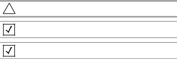
The following graphical alerts are used in this document to indicate notable situations:
NOTE Tips, hints, or special requirements that you should take note of.
! |
CAUTION Care is required. Disregarding a caution can result in data loss or equipment |
malfunction. |
WARNING! Indicates a condition or procedure that could result in personal injury or equipment damage.

6 |
AP-7562 Access Point |
1.2 AP-7562 Hardware
There are currently three AP-7562 Access Points:
Model Part Number |
|
Description |
|
|
|
|
|
AP-7562-67040-US |
AP-7562 |
Access Point outdoor IP67 dual radio 3x3:3 802.11 a/b/g/n/ac radio SKU: US |
|
|
|
|
|
AP-7562-67040-EU |
AP-7562 |
Access Point outdoor IP67 dual radio 3x3:3 802.11 a/b/g/n/ac radio SKU: EU |
|
|
|
|
|
AP-7562-67040-WR |
AP-7562 Access Point outdoor IP67 dual radio 3x3:3 802.11 a/b/g/n/ac radio SKU: WR |
|
|
|
|
|
|
|
|
|
|
NOTE All AP-7562 Access Points ship with one weatherized Ethernet adapter. AP-7562 Access Points do not ship with the Mounting Kit/Antenna and POE injector. These items must be ordered separately.
1.3 AP-7562 Antenna Accessories
NOTE Antennas must be ordered separately and are not included with the AP-7562.
The AP-7562 antenna suite includes the following optional antenna accessories. The antennas do not ship with the AP-7562 Access Points and must be ordered separately.
Installation Guide |
7 |
1.3.1 AP-7562 Dual Band 2.4 GHz / 5 GHz Antennas - US and Canada
Part Number |
Antenna Type |
2.4 GHz Peak Gain |
5.2 GHz Peak Gain |
|
|
|
|
ML-2452-HPAG4A6-01 |
Dipole |
4.0 |
7.3 |
|
|
|
|
ML-2452-HPA6X6-036 |
Dipole |
4.0 |
7.3 |
|
|
|
|
ML-2452-HPA6-01 |
Dipole |
5.3 |
6.1 |
|
|
|
|
ML-2452-PNA5-01R |
Panel |
5.5 |
6.0 |
|
|
|
|
ML-2452-PNL3M3-1 |
Polarized Panel |
9.7 |
9.2 |
|
|
|
|
1.3.2 AP-7562 Single Band 2.4 GHz Antennas - US and Canada
Part Number |
Antenna Type |
2.4 GHz Peak Gain |
|
|
|
ML-2499-FHPA5-01R |
Dipole |
5.3 |
|
|
|
ML-2499-HPA4-01 |
Dipole |
4.5 |
|
|
|
ML-2499-5PNL-72-N |
Panel |
6.5 |
|
|
|
1.3.3 AP-7562 Single Band 5 GHz Antenna - US and Canada
Part Number |
Antenna Type |
5.2 GHz Peak Gain |
|
|
|
ML-5299-HPA5-01 |
Dipole |
5.6 |
|
|
|
8 |
AP-7562 Access Point |
1.3.4 Outdoor Elevation Gain Configuration for US SKUs
Per FCC requirement, the use of the Access Point on UNII-1 band requires installers to input antenna elevation gain for dipole antennas during configuration. This information can be found in Zebra antenna guide document at www.zebra.com/support.
The applicable outdoor antennas on 5GHz band are shown below:
Index |
Antenna Type |
Part Number |
Elevation Gain |
|
|
|
|
1 |
Dipole |
ML-5299-HPA5-01 |
-2.53 |
|
|
|
|
2 |
Dipole |
ML-2452-HPAG4A6-01 |
5.7 |
|
|
|
|
3 |
Dipole |
ML-2452-HPA6X6-036 |
3.9 |
|
|
|
|
4 |
Dipole |
ML-2452-HPA6-01 |
4.09 |
|
|
|
|
1.3.5 AP-7562 Dual Band 2.4 GHz / 5 GHz Antennas - EU
Part Number |
Antenna Type |
2.4 GHz Peak Gain |
5.2 GHz Peak Gain |
|
|
|
|
ML-2452-HPAG5A8-01 |
Dipole |
7.5 |
8.0 |
|
|
|
|
ML-2452-PNA7-01R |
Panel |
8.0 |
12.0 |
|
|
|
|
ML-2452-PNL3M3-1 |
Polarized Panel |
9.7 |
9.2 |
|
|
|
|
1.3.6 AP-7562 Single Band 2.4 GHz Antennas - EU
Part Number |
Antenna Type |
2.4 GHz Peak Gain |
|
|
|
ML-2499-FHPA9-01R |
Dipole |
10.5 |
|
|
|
ML-2499-HPA8-01 |
Dipole |
8.0 |
|
|
|
1.3.7 AP-7562 Single Band 5 GHz Antenna - EU
Part Number |
Antenna Type |
5.2 GHz Peak Gain |
|
|
|
ML-5299-HPA10-01 |
Dipole |
10.5 |
|
|
|
ML-5299-HPA5-01 |
Dipole |
5.6 |
|
|
|

Installation Guide |
9 |
1.4 Hardware and Mounting Accessories
The AP-7562 is a Power over Ethernet (PoE) device. When deployed, the use of an outdoor rated PoE power supply and mounting bracket may be required. The recommended PoE accessories are listed in the following table:
Part Number |
Description |
|
|
|
|
AP-PSBIAS-7161-US |
Outdoor IP66 802.3AT gigabit Ethernet power injector, 100-240 |
VAC US |
|
|
|
AP-PSBIAS-7161-WW |
Outdoor IP66 802.3AT gigabit Ethernet power injector, 100-240 |
VAC International |
|
|
|
KT-153143-01 |
Outdoor PoE mounting kit |
|
|
|
|
1.5 AP-7562 Mounting Accessories
The AP-7562 has a flexible three piece mounting kit (KT-147407-01), together with an optional standoff extension arm (KT-150173-01) for pole mounting.
Part Number |
Description |
|
|
KT-147407-01 |
Hardware Mounting Kit |
|
|
KT-150173-01 |
12 inch extension arm for mounting kit |
|
|
1.6 AP-7562 Weatherized Ethernet Accessorys
One RJ45 weatherized connector plug is included with each AP-7562 Access Point. If additional plugs are required, they can be ordered using the part number listed in the following table:
|
Part Number |
|
Description |
|
|
|
|
|
|
KT-153676-01 |
|
RJ45 weatherized connector plug |
|
|
|
|
|
|
|
|
|
|||
|
|
|||
! |
CAUTION When connecting RJ45 cables, ensure that all cables are connected to the Access |
|||
|
Point from the bottom, and include a drip loop to prevent moisture intrusion. Cover |
|||
|
the Ethernet cable with self-healing weatherproofing tape. |
|||
|
|
|
|
|
|
|
|
|
|
Refer to the installation instructions included with the RJ45 weatherized connector plug for proper procedure to form a drip loop with the cable.
10 |
AP-7562 Access Point |
1.7 Package Contents
Carefully remove all protective packing material around the AP-7562 Access Point and save the container for storage. Refer to AP-7562 Hardware on page 6 when verifying all AP-7562 hardware has been received.
Record the serial numbers on the shipping cartons and AP-7562 for warranty claims and reference during software download procedures.
NOTE Record the serial numbers on the shipping cartons and AP-7562 Access Points for warranty claims and reference during software download procedures.
When opening the shipping cartons, inspect the equipment for damage. If you find any damaged equipment or any equipment is missing, contact Support immediately.
Each AP-7562 Access Point (see AP-7562 Hardware on page 6) includes the following parts:
•AP-7562 Access Point
•Weatherproof RJ45 plug kit
•AP-7562 Access Point Installation Guide (this document)
1.8Hardware Installation Guidelines
CAUTION All device wiring must comply with the National Electric Code (NEC) or regulations ! and procedures defined by the regulatory bodies of the country or region where the
devices are being deployed. All local building and structure codes must be observed.
WARNING! Strictly observe safety precautions and warnings when installing an AP-7562 Access Point.
Installation Guide |
11 |
1.8.1 Precautions
Before installing an AP-7562 Access Point, verify the following grounding and lightning protection guidelines:
•The installation professional should be familiar with all grounding requirements and regional codes and ensure the Access Point and mounting asset are properly grounded. The grounding cable for an AP-7562 must be at a minimum a #10 gauge wire cross section. The cable can be attached to the unit using one of the following methods:
•Loosen the grounding screw, insert the grounding cable into the hole below it, and tighten the screw.
•Loosen the grounding screw, wind the grounding cable around it, and tighten the screw.
•Attach a ring lug to the grounding cable and secure it to the unit using the grounding screw.
•To properly attach the grounding cable to the Access Point, refer to AP-7562 Grounding Post on page 16.
•For Ethernet and lightning protection, it is recommended that a commercially available off-the-shelf Lightning Protection Unit (LPU) be used on all shielded CAT5E Ethernet connections. The LPU should be rated for outdoor use.
•For the best possible protection, each Access Point requires an LPU be installed adjacent to the Access Point. If there is a LAN connection to an indoor network, a second LPU is required at the cable entry point to the building.
CAUTION Lightning damage is not covered under the conditions of a standard product
! warranty. When installed correctly, Lightning Protection Units (LPUs) provide the best protection from the harmful effects of lightning. Observe all regional and national codes that apply for lightning protection.
•Verify the deployment environment has a continuous temperature range compatible with the operating temperature range of the device.
12 |
AP-7562 Access Point |
1.8.2 Warnings
• Read all installation instructions and site survey reports, and verify correct equipment installation before connecting the Access Point to its power source.
• Remove jewelry and watches before installing this equipment.
• Verify the unit is grounded before connecting it to the power source.
• Verify any device connected to this unit is properly wired and grounded.
• Connect all power cords to a properly wired and grounded electrical circuit. Verify the electrical circuits have appropriate overload protection.
• Attach only approved power cords to the device.
• Verify the power connector and socket are accessible at all times during the operation of the equipment.
• Do not hold any component containing a radio such that it is very close to or touching any exposed parts of the body, especially the face or eyes, while transmitting.
• Do not work with power circuits in dimly lit spaces.
• Do not install this equipment or work with its power circuits during thunderstorms or other weather conditions that could cause a power surge.
• Verify there is adequate ventilation around the device, and that ambient temperatures meet equipment operation specifications.
• Avoid contact with overhead power lines.
• Take precautions to avoid injury from falling tools and equipment. Crews should wear hard hats in and around the installation work site.
• Be aware of vehicular traffic in and around the installation work site.
• Do not operate a portable transmitter near unshielded blasting caps or in an environment where explosives are present unless the transmitter is especially certified for such use.
• Refer to your site survey and network analysis reports to determine specific requirements for each deployment.
• Assign installation responsibility to the appropriate personnel.
• Identify and document where all installed components are located.
• Identify and prepare Ethernet and console port connections.
• Verify cable lengths are within the maximum allowable distances for optimal signal transmission.
! |
CAUTION |
The maximum length allowed for PoE cables is 100 meters. |
|
||
|
|
|
|
|
|
|
|
|
|
|
|
! |
CAUTION When connecting RJ45 cables, ensure that all cables are connected to the Access |
|
|
Point from the bottom, and include a drip loop to prevent moisture intrusion. |
|
|
|
|
|
|
|
Installation Guide |
13 |
1.9 Access Point Placement
Observe the following recommended guidelines:
•Identify each piece of the mounting bracket and mounting extension arm hardware and ancillary hardware.
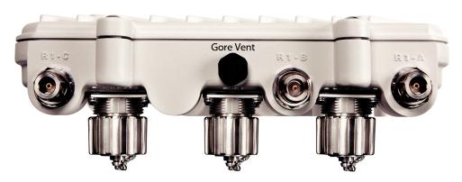
•Mount the device with the black gore vent down.
•Mounting height for network devices should not exceed 30 to 35 feet. Mounting height should vary to accommodate the topography of the deployment area, foliage, and other obstructions.
•Devices can be deployed using any of the recommended outdoor deployment procedures.
•Line of Sight (LoS) guidelines should be given special consideration when deploying devices.
1.10AP-7562 Hardware Overview
The AP-7562 is a 3x3:3 802.11ac Access Point utilizing one 2.4 GHz 802.11n radio and one 5 GHz 802.11ac radio.
An AP-7562 must be installed by trained professionals familiar with RF planning and regulatory limits defined by the regulatory bodies of the country where the devices are being deployed. All common precautions for grounding and Electrostatic Discharge (ESD) protection should be observed during deployment and installation. AP-7562 Access Points must be installed such that no harmful interference results from device operation.
1.10.1 AP-7562 Ports and Connections
The AP-7562 Access Point has the following port designations:
•Antenna ports R1-A, B and C, R2-A, B and C
•Console port
•GE1/POE - LAN port
•GE2 - WAN port

14 |
AP-7562 Access Point |
1.10.2 AP-7562 Antenna Connectors
AP-7562 Access Points (AP-7562-67040-US, AP-7562-67040-EU and AP-7562-67040-WR) are configured with six N type connectors to support two active WLAN data radios.
WARNING! Antenna ports where no antenna is mounted must be properly terminated using an approved IP67 terminator.
WARNING! All antenna connectors should be covered with weatherproofing tape.
Installation Guide |
15 |
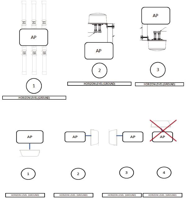
1.10.3 Antenna Mounting Guidelines
The following are examples of acceptable mounting for dipole antenna deployments:
The following are examples of acceptable mounting methods for panel antenna deployments:

16 |
AP-7562 Access Point |
1.10.4 AP-7562 Grounding Post
The grounding post is located on the bottom of the Access Point above the GND symbol.
WARNING! The grounding cable for an AP-7562 must be at a minimum a #10 gauge wire cross section.
The grounding cable can be attached to the unit using one of the following methods:
•Use a grounding screw to securely attach the grounding cable to the grounding post. Use an 8mm socket and driver to tighten the grounding screw to 30 inch pounds (lbf-in).
•Attach a ring lug to the grounding cable and use a grounding screw to securely attach the ring lug to the Access Point. Use an 8mm socket and driver to tighten the grounding screw to 30 inch pounds (lbf-in).
Installation Guide |
17 |
1.11 LED Indicators
AP-7562 Access Points have LED activity indicators on the front of the enclosure. The LEDs provide a status display indicating error conditions, transmission, and network activity for the 2.4 GHz radio (green) and the 5 GHz radio (amber).
Task |
2.4 GHz Activity LED (Green) |
5 GHz Activity LED (Amber) |
|
|
|
Unconfigured |
On |
On |
Radio |
|
|
|
|
|
Normal |
• If this radio band is enabled: |
• If this radio band is enabled: |
Operation |
Blink at 5 second interval |
Blink at 5 second interval |
|
• If this radio band is disabled: |
• If this radio band is disabled: |
|
Off |
Off |
|
• If there is activity on this band: |
• If there is activity on this band: |
|
Blink interval at 1 time per second |
Blink interval at 1 time per second |
|
|
|
Firmware |
Off |
On |
Update |
|
|
|
|
|
Locate AP |
LEDs blink in an alternating green, red and |
LEDs blink in an alternating green, red and |
Mode |
amber pattern using an irregular blink rate. |
amber pattern using an irregular blink rate. |
|
This LED state in no way resembles normal |
This LED state in no way resembles normal |
|
operating conditions |
operating conditions. |
|
|
|
18 |
AP-7562 Access Point |
2 AP-7562 Hardware Mounting and Installation
The AP-7562 mounting bracket kit (KT-147407-01) is recommended for most deployments.. When a standoff distance is required for a pole mounted or wall mounted installation, use the extension arm kit (KT-150173-01).
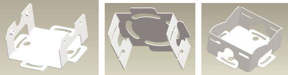
2.1 Mounting Bracket Kit
The AP-7562 mounting bracket kit (KT-147407-01) includes the Access Point bracket (left), angle adapter bracket (center), and pole mount bracket (right) sections:
The Access Point bracket and angle adapter bracket can be rotated (plus or minus 15 degrees) and tilted (up to 45 degrees) to orient the unit for optimal positioning.
The following ancillary hardware to assemble the mounting bracket is included in the kit:
Description |
Quantity |
|
|
M6 serrated hex flanged screws |
7 |
|
|
1/2 inch hex head nut |
2 |
|
|
1/2 inch x 3/4 inch hex head bolt |
2 |
|
|
A torque wrench or ratchet with a 10mm adapter, or an adjustable wrench, can be used to assemble the mounting brackets.
Installation Guide |
19 |
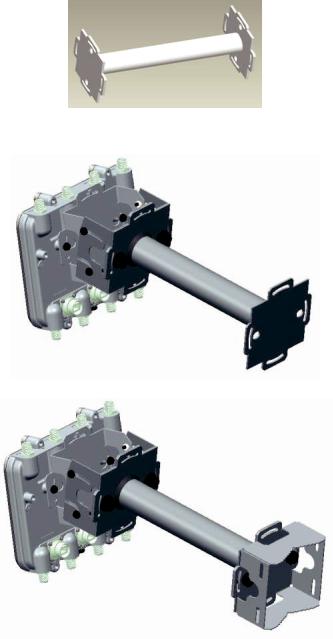
2.1.1 Extension Arm Kit
When mounting an AP-7562 on poles more than 3 inches in diameter, use the extension arm kit (KT-150173-01) to provide a minimum standoff distance of twelve inches to avoid interference with the antennas.
The extension arm kit can also be used in combination with the any of the brackets from the mounting bracket kit.
20 |
AP-7562 Access Point |
The following ancillary hardware to attach the extension arm to the mounting bracket kit is included in the extension arm kit:
Description |
Quantity |
|
|
1/2 inch hex head nut |
2 |
|
|
1/2 inch x 3/4 inch hex head bolt |
2 |
|
|
2.2 Pole Mounted Installations
The mounting hardware kit and extension arm can be used in various combinations to properly install the AP-7562 on a pole. For poles of up to 3 inches in diameter, attach the pole mount bracket of the mounting hardware kit at the desired position on the pole using band clamps up to 3/4 inch width, or a 1/2 inch x 4 inch wide U-bolt and nuts. For poles greater than 3 inches in diameter, attach the pole mount bracket using band clamps.
!CAUTION Always mount the AP-7562 with the black gore vent facing down.
NOTE The U-bolt and band clamps are not included in the mounting bracket kit.
NOTE Use of the extension arm is recommended for installations on poles greater than 3 inches in diameter.
Loading...