

Page 1
CC600/CC6000
Customer Concierge
Integrator Guide
for Android ™ 8.1.0 Oreo
MN-003411-02EN
Page 2

Copyright
ZEBRA and the stylized Zebra head are trademarks of Zebra Technologies Corporation, registered in many
jurisdictions worldwide. All other trademarks are the property of their respective owners.
©2019-2020 Zebra Technologies Corporation and/or its affiliates. All rights reserved. Google ™ , Android,
Google Play™ and other marks are trademarks of Google LLC; Oreo is a trademark of Mondelez International,
Inc. group. All other trademarks are the property of their respective owners.
COPYRIGHTS & TRADEMARKS: For complete copyright and trademark information, go to www.zebra.com/
copyright.
WARRANTY: For complete warranty information, go to www.zebra.com/warranty.
END USER LICENSE AGREEMENT: For complete EULA information, go to www.zebra.com/eula.
Terms of Use
• Proprietary Statement
This manual contains proprietary information of Zebra Technologies Corporation and its subsidiaries
(“Zebra Technologies”). It is intended solely for the information and use of parties operating and maintaining
the equipment described herein. Such proprietary information may not be used, reproduced, or disclosed to
any other parties for any other purpose without the express, written permission of Zebra Technologies.
• Product Improvements
Continuous improvement of products is a policy of Zebra Technologies. All specifications and designs are
subject to change without notice.
• Liability Disclaimer
Zebra Technologies takes steps to ensure that its published Engineering specifications and manuals are
correct; however, errors do occur. Zebra Technologies reserves the right to correct any such errors and
disclaims liability resulting therefrom.
• Limitation of Liability
In no event shall Zebra Technologies or anyone else involved in the creation, production, or delivery of the
accompanying product (including hardware and software) be liable for any damages whatsoever (including,
without limitation, consequential damages including loss of business profits, business interruption, or loss of
business information) arising out of the use of, the results of use of, or inability to use such product, even if
Zebra Technologies has been advised of the possibility of such damages. Some jurisdictions do not allow
the exclusion or limitation of incidental or consequential damages, so the above limitation or exclusion may
not apply to you.
Revision History
Changes to the original guide are listed below:
Change Date Description
-01 Rev A 4/2019 Initial Release
-02EN Rev A 8/2020 Removed duplicate screen captures.
Removed Imager as Camera.
Labeled the proximity sensor in Figure 1.
Updated Documentation Set, Supported Decoders, and Transferring Files with a
Host Computer via USB sections.
2
Page 3

Table of Contents
Copyright ......................................................................................................................... 2
Terms of Use ..................................................................................................................2
Revision History ..............................................................................................................2
About This Guide........................................................................................................ 10
Introduction ................................................................................................................... 10
Documentation Set ....................................................................................................... 10
Configurations .............................................................................................................. 11
Accessories ...................................................................................................................11
Software Versions ......................................................................................................... 12
Chapter Descriptions .................................................................................................... 13
Notational Conventions ................................................................................................ 14
Service Information ....................................................................................................... 14
Provide Documentation Feedback ................................................................................ 14
Getting Started............................................................................................................ 15
Introduction ................................................................................................................... 15
Unpacking .....................................................................................................................15
Features ....................................................................................................................... 16
Setup ............................................................................................................................. 20
Inserting the microSD Card (Optional) .......................................................................... 21
Mounting the Device ..................................................................................................... 21
Google Account Setup .......................................................................................... 28
Zebra Visibility Services ........................................................................................ 28
Resetting the Device ..................................................................................................... 28
Settings........................................................................................................................ 30
Introduction ................................................................................................................... 30
WLAN Configuration ..................................................................................................... 30
3
Page 4

Table of Contents
Configuring a Secure Wi-Fi Network ..................................................................... 30
Manually Adding a Wi-Fi Network ......................................................................... 32
Configuring for a Proxy Server .............................................................................. 33
Configuring the Device to Use a Static IP Address ............................................... 34
Wi-Fi Preferences .................................................................................................. 35
Additional Wi-Fi Settings ....................................................................................... 36
Wi-Fi Direct ............................................................................................................ 38
Setting Screen Lock ...................................................................................................... 38
Setting Screen Lock Using PIN ............................................................................. 39
Setting Screen Unlock Using Password ................................................................ 40
Setting Screen Unlock Using Pattern .................................................................... 41
Showing Passwords ...................................................................................................... 41
Accounts ....................................................................................................................... 42
Language Usage ........................................................................................................... 42
Changing the Language Setting ............................................................................ 42
Adding Words to the Dictionary ............................................................................. 42
Keyboard Settings ................................................................................................. 42
PTT Express Configuration ................................................................................... 43
RxLogger ......................................................................................................................43
RxLogger Configuration ........................................................................................ 43
RxLogger Settings ........................................................................................................ 44
ANR Module .................................................................................................... 44
Kernal Module ................................................................................................. 44
Logcat Module ................................................................................................ 45
LTS Module ..................................................................................................... 46
Ramoops Module ............................................................................................ 46
Resource Module ............................................................................................ 47
Snapshot Module ............................................................................................ 47
TCPDump Module .......................................................................................... 48
Tombstone Module ......................................................................................... 48
Configuration File .................................................................................................. 48
Enabling Logging ................................................................................................... 48
Disabling Logging .................................................................................................. 48
Extracting Log Files ............................................................................................... 48
RxLogger Utility ..................................................................................................... 49
App View ....................................................................................................................... 49
Viewing Logs ................................................................................................... 50
Backup ............................................................................................................ 51
Archive Data ................................................................................................... 52
Overlay View ......................................................................................................... 52
Initiating the Main Chat Head .......................................................................... 52
Removing the Main Chat Head ....................................................................... 52
Viewing Logs ................................................................................................... 53
4
Page 5

Table of Contents
Removing a Sub Chat Head Icon ................................................................... 54
Backing Up In Overlay View ........................................................................... 54
About Phone ................................................................................................................. 54
USB/Ethernet Communication................................................................................... 56
Introduction ................................................................................................................... 56
Transferring Files with a Host Computer via USB ........................................................ 56
Transferring Files .................................................................................................. 56
Transferring Photos ............................................................................................... 57
Disconnect from the Host Computer ..................................................................... 57
USB/Ethernet Communication ..................................................................................... 58
Ethernet Settings ................................................................................................... 58
Configuring Ethernet Proxy Settings ..................................................................... 58
Configuring Ethernet Static IP Address ................................................................. 59
Establishing Ethernet Connection ......................................................................... 60
DataWedge .................................................................................................................. 61
Introduction ................................................................................................................... 61
Basic Scanning ............................................................................................................. 61
Barcode Capture with an Imager ........................................................................... 61
Profiles .......................................................................................................................... 62
Profile0 .................................................................................................................. 62
Plug-ins ................................................................................................................. 63
Input Plug-ins ........................................................................................................ 63
Process Plug-ins ................................................................................................... 63
Output Plug-ins ...................................................................................................... 63
Profiles Screen .............................................................................................................. 64
Profile Context Menu ............................................................................................. 64
Options Menu ........................................................................................................ 65
Disabling DataWedge ............................................................................................ 65
Creating a New Profile .................................................................................................. 65
Profile Configuration ..................................................................................................... 66
Associating Applications ........................................................................................ 66
Data Capture Plus ................................................................................................. 68
Barcode Input ................................................................................................................ 70
Enabled ........................................................................................................... 70
Scanner Selection ........................................................................................... 70
Auto Switch to Default on Event ..................................................................... 70
Configure Scanner Settings ............................................................................ 71
Decoders ......................................................................................................... 71
Decoder Params ............................................................................................. 74
5
Page 6

Table of Contents
Codabar .......................................................................................................... 74
UPC EAN Params ........................................................................................... 79
Reader Params ............................................................................................... 81
Scan Params .................................................................................................. 84
UDI Params .................................................................................................... 85
Keep enabled on suspend .............................................................................. 85
Voice Input ............................................................................................................ 85
Keystroke Output ................................................................................................... 86
Intent Output .......................................................................................................... 87
Intent Overview ............................................................................................... 88
IP Output ............................................................................................................... 89
Usage .............................................................................................................. 90
Using IP Output with IPWedge .............................................................................. 91
Using IP Output without IPWedge .................................................................. 92
Generating Advanced Data Formatting Rules .............................................................. 93
Configuring ADF Plug-in ........................................................................................ 93
Creating a Rule ..................................................................................................... 94
Defining a Rule ............................................................................................... 95
Defining Criteria .............................................................................................. 95
Defining an Action ........................................................................................... 97
Deleting a Rule ............................................................................................... 97
Order Rules List .............................................................................................. 97
Deleting an Action ........................................................................................... 98
ADF Example .................................................................................................. 98
DataWedge Settings ................................................................................................... 102
Importing a Configuration File ....................................................................... 102
Exporting a Configuration File ............................................................................. 103
Importing a Profile File ........................................................................................ 103
Exporting a Profile ............................................................................................... 103
Restoring DataWedge ......................................................................................... 104
Configuration and Profile File Management ................................................................ 104
Enterprise Folder ................................................................................................. 104
Auto Import .......................................................................................................... 104
Programming Notes ............................................................................................ 105
Capture Data and Taking a Photo in the Same Application ................................ 105
Disable DataWedge on Device and Mass Deploy ............................................... 105
DataWedge APIs ................................................................................................. 105
Reporting ............................................................................................................. 105
Soft Scan Trigger ................................................................................................ 106
Function Prototype ........................................................................................ 106
Scanner Input Plugin ........................................................................................... 106
Function Prototype .............................................................................................. 106
Parameters ................................................................................................... 106
Return Values ............................................................................................... 106
6
Page 7

Table of Contents
Example ........................................................................................................ 107
Comments ..................................................................................................... 107
Enumerate Scanners ........................................................................................... 107
Function Prototype ........................................................................................ 108
Parameters ................................................................................................... 108
Return Values ............................................................................................... 108
Example ........................................................................................................ 109
Comments ..................................................................................................... 109
Set Default Profile ............................................................................................... 110
Default Profile Recap .................................................................................... 110
Usage Scenario ............................................................................................ 110
Function Prototype ........................................................................................ 110
Parameters ................................................................................................... 110
Return Values ............................................................................................... 110
Example ........................................................................................................ 111
Comments ..................................................................................................... 111
Reset Default Profile ........................................................................................... 111
Function Prototype ........................................................................................ 112
Parameters ................................................................................................... 112
Return Values ............................................................................................... 112
Example ........................................................................................................ 112
Comments ..................................................................................................... 112
Switch To Profile ................................................................................................. 113
Profiles Recap ............................................................................................... 113
Usage Scenario ............................................................................................ 113
Function Prototype ........................................................................................ 113
Parameters ................................................................................................... 113
Return Values ............................................................................................... 114
Example ........................................................................................................ 114
Comments ..................................................................................................... 114
Notes ............................................................................................................. 115
Application Deployment........................................................................................... 116
Introduction ................................................................................................................. 116
Security ....................................................................................................................... 116
Secure Certificates ...................................................................................................... 116
Installing a Secure Certificate ..................................................................................... 116
Configuring Credential Storage Settings ............................................................. 117
Development Tools ..................................................................................................... 117
Android ................................................................................................................ 117
EMDK for Android ............................................................................................... 118
StageNow ............................................................................................................ 119
ADB USB Setup .......................................................................................................... 119
Enabling USB Debugging ........................................................................................... 119
7
Page 8

Table of Contents
Application Installation ................................................................................................ 120
Installing Applications Using the USB Connection .............................................. 120
Installing Applications Using the Android Debug Bridge ..................................... 121
Installing Applications Using a microSD Card ..................................................... 122
Uninstalling an Application .................................................................................. 123
Performing a System Update ...................................................................................... 124
Downloading the System Update Package ......................................................... 124
Using microSD Card ............................................................................................ 124
Using ADB ........................................................................................................... 125
Verify System Update Installation ....................................................................... 126
Performing an Enterprise Reset .................................................................................. 126
Downloading the Enterprise Reset Package ....................................................... 126
Using microSD Card ............................................................................................ 126
Using ADB ........................................................................................................... 127
Performing a Factory Reset ........................................................................................ 127
Downloading the Factory Reset Package ........................................................... 127
Using microSD Card ............................................................................................ 128
Using ADB ........................................................................................................... 128
Storage .......................................................................................................................129
Random Access Memory .................................................................................... 129
Internal Storage ................................................................................................... 130
External Storage .................................................................................................. 131
Formatting a microSD Card .......................................................................... 132
Formatting as Internal Memory ..................................................................... 133
Enterprise Folder ................................................................................................. 134
App Management ........................................................................................................ 134
Viewing App Details .................................................................................................... 136
Managing Downloads ................................................................................................. 136
Maintenance and Troubleshooting ......................................................................... 137
Introduction ................................................................................................................. 137
Maintaining the Device ................................................................................................ 137
Cleaning Instructions .................................................................................................. 137
Approved Cleanser Active Ingredients ................................................................ 137
Harmful Ingredients ............................................................................................. 138
Device Cleaning Instructions ...................................................................................... 138
Special Cleaning Notes ....................................................................................... 138
Cleaning Materials Required ............................................................................... 138
Cleaning Frequency ............................................................................................ 138
Cleaning the Device ............................................................................................ 139
Housing ............................................................................................................... 139
8
Page 9

Table of Contents
Display ................................................................................................................. 139
Camera and Exit Window .................................................................................... 139
Troubleshooting ......................................................................................................... 140
Technical Specifications.......................................................................................... 142
Introduction ................................................................................................................. 142
Technical Specifications ............................................................................................. 142
CC6000 ............................................................................................................... 142
CC600 ................................................................................................................. 144
Decode Distances ...................................................................................................... 146
CC6000 - SE4710 Scan Engine .......................................................................... 146
CC600 - SE2100 Scan Engine ............................................................................ 147
9
Page 10

About This Guide
Introduction
This guide provides information about using the CC600 and CC6000 Customer Concierge and
accessories.
NOTE: Screens and windows pictured in this guide are samples and can differ from actual screens.
Documentation Set
The documentation set provides information for specific user needs, and includes:
• CC600/CC6000 Customer Concierge Quick Start Guide for Android Version 8.1, p/n
MN-003315-xx, - describes how to get the device up and running.
• CC600/CC6000 Customer Concierge User Guide for Android Version 8.1, p/n MN-003313-xx, describes how to use the device.
• CC600/CC6000 Customer Concierge Integrator Guide for Android Version 8.1, p/n MN-003411-xx,
- describes how to set up the device and accessories.
For the latest version of this guide and all guides, go to: www.zebra.com/support
10
Page 11
Configurations
This guide covers the configurations listed in Table 1 and Table 2.
Table 1 CC600 Device Configurations
About This Guide
Configuration Description
CC600-5-3200LNWW 5 inch, OS: Android ™ 8.1.0 Oreo, 32GB,
Ethernet/Wi-Fi, Imager, Worldwide
Configuration
CC600-5-3200LNNA 5 inch, OS: Android ™ 8.1.0 Oreo, 32GB,
Ethernet/Wi-Fi, Imager, North America
Configuration
CC600-5-3200LNEU 5 inch, OS: Android ™ 8.1.0 Oreo, 32GB,
Ethernet/Wi-Fi, Imager, Europe Configuration
CC600-5-3200LNIN 5 inch, OS: Android ™ 8.1.0 Oreo, 32GB,
Ethernet/Wi-Fi, Imager, India Configuration
Table 2 CC6000 Device Configurations
Configuration Description
CC6000-10-3200LCWW 10 inch, OS: Android ™ 8.1.0 Oreo, 32GB,
Landscape, Imager, Worldwide Configuration
Front
Camera
No SE2100
No SE2100
No SE2100
No SE2100
Front
Camera
No SE4710
Scan
Engine
Scan
Engine
CC6000-10-3200PCWW 10 inch, OS: Android ™ 8.1.0 Oreo, 32GB,
CC6000-10-3200LCNA 10 inch, OS: Android ™ 8.1.0 Oreo, 32GB,
CC6000-10-3200PCNA 10 inch, OS: Android ™ 8.1.0 Oreo, 32GB,
CC6000-10-3200LNNA 10 inch, OS: Android ™ 8.1.0 Oreo, 32GB,
Accessories
Table 3 Accessories
Mounting Plates
CC600 Wall Mount 21-118517-01R CC600 Wall Mounting Kit
CC600 Pole Mount 21-118517-02R CC600 Pole Mounting Kit
Yes SE4710
Portrait, Imager, Worldwide Configuration
Yes SE4710
Portrait, Imager, North America Configuration
Yes SE4710
Portrait, Imager, North America Configuration
No SE4710
Landscape, Imager, North America
Configuration
Accessory Part Number Description
11
Page 12

Table 3 Accessories
Accessory Part Number Description
CC6000 Wall Mounting
Kit
CC6000 Wall Mounting
Kit
CC6000 Wall Mounting
Kit
About This Guide
KT-152097-03 CC6000 Wall Mounting Kit with Power
Supply Storage
KT-152097-01 100mm VESA
KT-152098-03 Slimmer, CC6000 specific mount
CC6000 Pole Mounting
Kit
CC6000 Pole Mounting
Kit
Communication Cables
USB-C Cable CBL-TC2X-USBC-01 Used to communicate with CC6000 via the
USB-C Cable CBL-TC5X-USBC2A-01 Used to communicate with CC6000 via the
Power Supplies
DC Line Cord CBL-DC-383A1-01 Used with Power Supply
Power Supply PWR-BUA5V16W0WW 100-240VAC, 5.4V, 3A, 16W
KT-152096-03 100mm VESA
Includes additional storage shelf to hold
power supply
Modified over KT0152096-02 to better hold
Level VI power supply.
KT-152096-01 100mm VESA
USB OTG port.
USB OTG port.
(PWR-BUA5V16W0WW)
Cable length is 6 ft
Meets US DOE Level VI efficiency
standard
Replaces PWRS-14000-249R
AC Line Cord 50-16000-182R Used with
Software Versions
To determine the current software versions:
1. Swipe down from the top to open Quick Settings.
2. Touch > System.
3. Touch About phone.
50-14000-147R/50-14000-249R?PWRS-1
4000-249R/PWR-BUA5V16W0WW
12
Page 13

4. The following information displays:
• Status
• SW Components
• Legal Information
• Model
• Android version
• Android security patch level
• Kernel version
• Build Fingerprint
• Build number
To determine the device serial number, touch About Phone > Status. Serial number displays.
Chapter Descriptions
Topics covered in this guide are as follows:
• Getting Started provides information on getting the device up and running for the first time.
• Settings provides the settings for configuring the device.
• USB/Ethernet Communication describes how to connect the device to a host computer using USB and
Ethernet.
• DataWedge describes how to use and configure the DataWedge application.
• Application Deployment provides information for developing and managing applications.
• Maintenance and Troubleshooting includes instructions on cleaning and storing the device, and provides
troubleshooting solutions for potential problems during device operation.
• Technical Specifications provides the technical specifications for the device.
About This Guide
13
Page 14

Notational Conventions
The following conventions are used in this document:
• “Device” refers to all configurations of the CC600 Customer Concierge and CC6000 Customer Concierge.
• Bold text is used to highlight the following:
• Dialog box, window and screen names
• Drop-down list and list box names
• Check box and radio button names
• Icons on a screen
• Key names on a keypad
• Button names on a screen.
• Bullets (•) indicate:
• Action items
• Lists of alternatives
• Lists of required steps that are not necessarily sequential.
• Sequential lists (e.g., those that describe step-by-step procedures) appear as numbered lists.
About This Guide
Service Information
If you have a problem with your equipment, contact Customer Support for your region. Contact information is
available at: zebra.com/support
When contacting support, please have the following information available:
• Serial number of the unit (found on manufacturing label)
• Model number or product name (found on manufacturing label)
• Software type and version number
• IMEI number.
Customer Support responds to calls by email or telephone within the time limits set forth in support
agreements.
If the problem cannot be solved by Customer Support, the user may need to return the equipment for servicing
and will be given specific directions. We are not responsible for any damages incurred during shipment if the
approved shipping container is not used. Shipping the units improperly can possibly void the warranty.
Remove the SIM card and/or microSD card from the device before shipping for service.
If the device was purchased from a business partner, contact that business partner for support.
.
Provide Documentation Feedback
If you have comments, questions, or suggestions about this guide, send an email to
EVM-Techdocs@zebra.com
.
14
Page 15

Getting Started
Introduction
This chapter provides information for getting the device up and running for the first time.
Unpacking
1. Carefully remove all protective material from the device and save the shipping container for later
storage and shipping.
2. Verify that the following are included:
• CC600 or CC6000 interactive kiosk.
• Regulatory Guide.
• CC600 only: Ferrite bead for EMI. Attaches to the DC power module.
3. Inspect the equipment for damage. If any equipment is missing or damaged, contact the Global
Customer Support center immediately.
4. Prior to using the device for the first time, remove the protective shipping film that covers the
display.
15
Page 16

Features
Front
Facing
Camera
Touch
Screen and
Display
Speaker
NFC
Antenna
Speaker
Exit Window (Scanner)
Microphone
Proximity Sensor
Mounting
Bracket
Screw
Holders
Micro SD
Card Slot
Audio
Adjustment/
Programmable
Buttons
Reset Button
Figure 1 CC6000 Front View
Getting Started
NOTE: Although the orientations differ, the features on the CC6000 landscape and portrait devices are the
same.
Figure 2 CC6000 Back View
16
Page 17
Getting Started
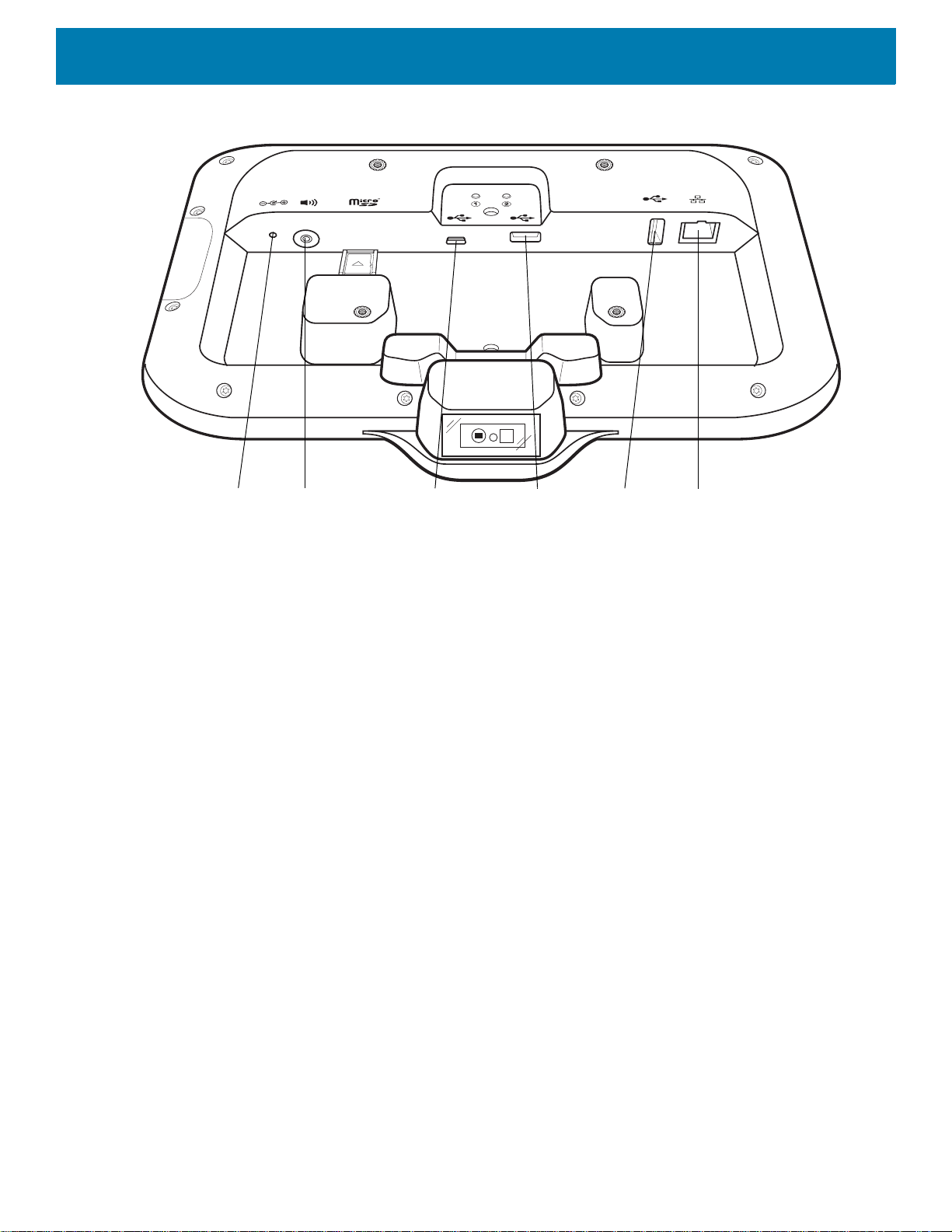
USB C Port
(Used for
External
display or
OTG)
Power
Port
Audio
Port
USB A
Port
USB A
Port
Ethernet with POE
Figure 3 CC6000 Power and Cable Ports
17
Page 18

Getting Started
Mounting
Bracket
Mounting
Bracket Screw
Holders
Mounting
Bracket
Locking
Screw
Wall Mount
Screw
Holes
Speaker
Exit Window
(Scanner)
Proximity Sensor
Microphone
Touch
Screen and
Display
Figure 4 CC6000 Back With Bracket View
Figure 5 CC600 Front Views
18
Page 19
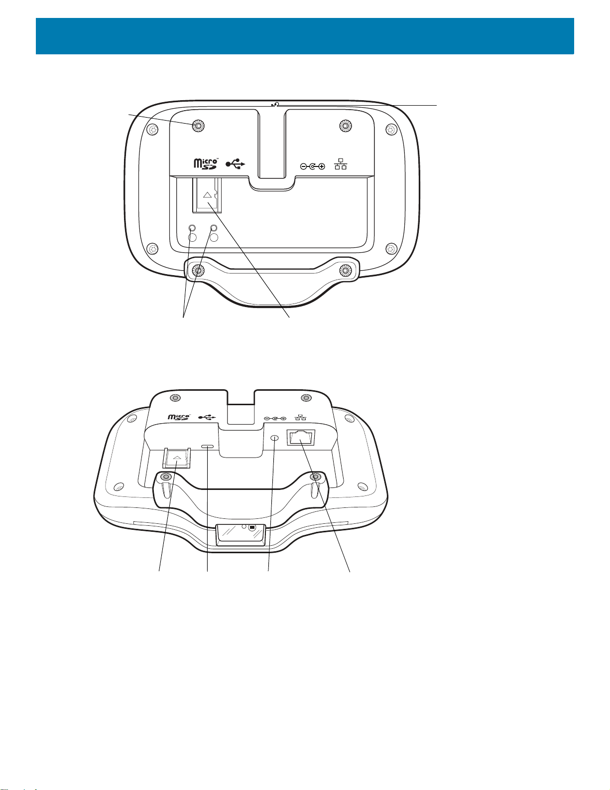
Figure 6 CC600 Back View
Reset Button
Mounting
Bracket
Screw
Holders
(4)
Micro SD
Card Slot
Audio
Adjustment/Programmable
Buttons
x
USB C Port
(Used for
External
display or
OTG and other
USB-2
peripherals)
Power
Port
Micro SD
Card Slot
Ethernet with POE
Getting Started
21
Figure 7 CC600 Power and Cable Ports
19
Page 20
Getting Started
21
Mounting
Bracket
Mounting
Bracket Screw
Holders
Mounting
Bracket
Locking
Screw
Wall Mount
Screw
Holes
Figure 8 CC600 Back With Bracket View
Table 4 Feature Descriptions
Item Function
Touch Screen and
Displays all information needed to operate the device.
Display
Exit Window
(Scanner)
Provides data capture using the imager and reads a barcode.
Note: To read a barcode, a scan-enabled app is required on the device.
Speaker Provides audio output for video and music playback. Provides audio in
speaker-phone mode.
NFC Antenna Reads NFC tags. (CC6000 Only)
Proximity Sensor Identifies the proximity of a user for turning up the display.
Microphone Use for communications in Speakerphone mode.
Front Facing Camera Captures still photos and videos.
Note: Select CC6000 devices only.
Interface Connectors See Figure 3 and Figure 7.
Volume Up/Down
Button
External Display Designated for USB-C port utilization.
Increase and decrease audio volume (programmable).
Setup
Perform this procedure to start using the device for the first time.
• Install a micro secure digital (SD) card (optional).
• Connect the power supply to power on the device.
• Configure the device.
20
Page 21
Getting Started
• Mount the device with the mounting bracket.
• Setup a Google account.
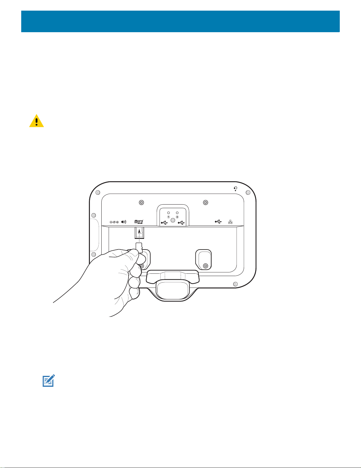
Inserting the microSD Card (Optional)
The microSD card slot provides secondary non-volatile storage. The slot is located on the back of the device to
the right of the audio jack. Refer to the documentation provided with the card for more information, and follow
the manufacturer’s recommendations for use.
CAUTION: Follow proper electrostatic discharge (ESD) precautions to avoid damaging the microSD card. Proper ESD pre-
cautions include, but are not limited to, working on an ESD mat and ensuring that the operator is properly grounded.
To install the microSD card:
1. Remove the device from the mounting bracket, if installed.
2. Slide the microSD card, connectors down, into the device as shown in Figure 9.
Figure 9 Inserting microSD Card
Mounting the Device
Each configuration of the device requires the appropriate mounting bracket to mount the device to a wall or
other flat surface. The diameter of the holes for the wall screws is 5.8mm (0.228 in).
NOTE: Device measurements in Figure 10, Figure 11 and Figure 12 are in millimeters.
21
Page 22
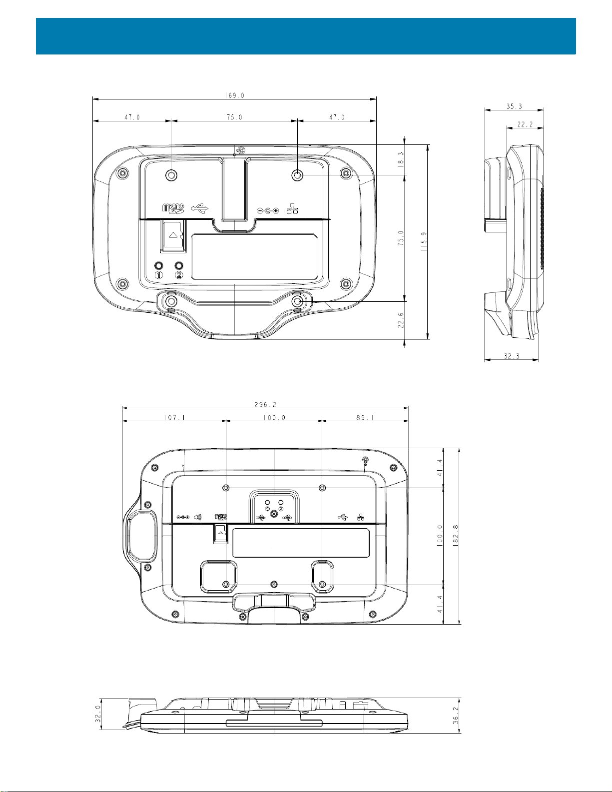
Figure 10 CC600 Measurements
Getting Started
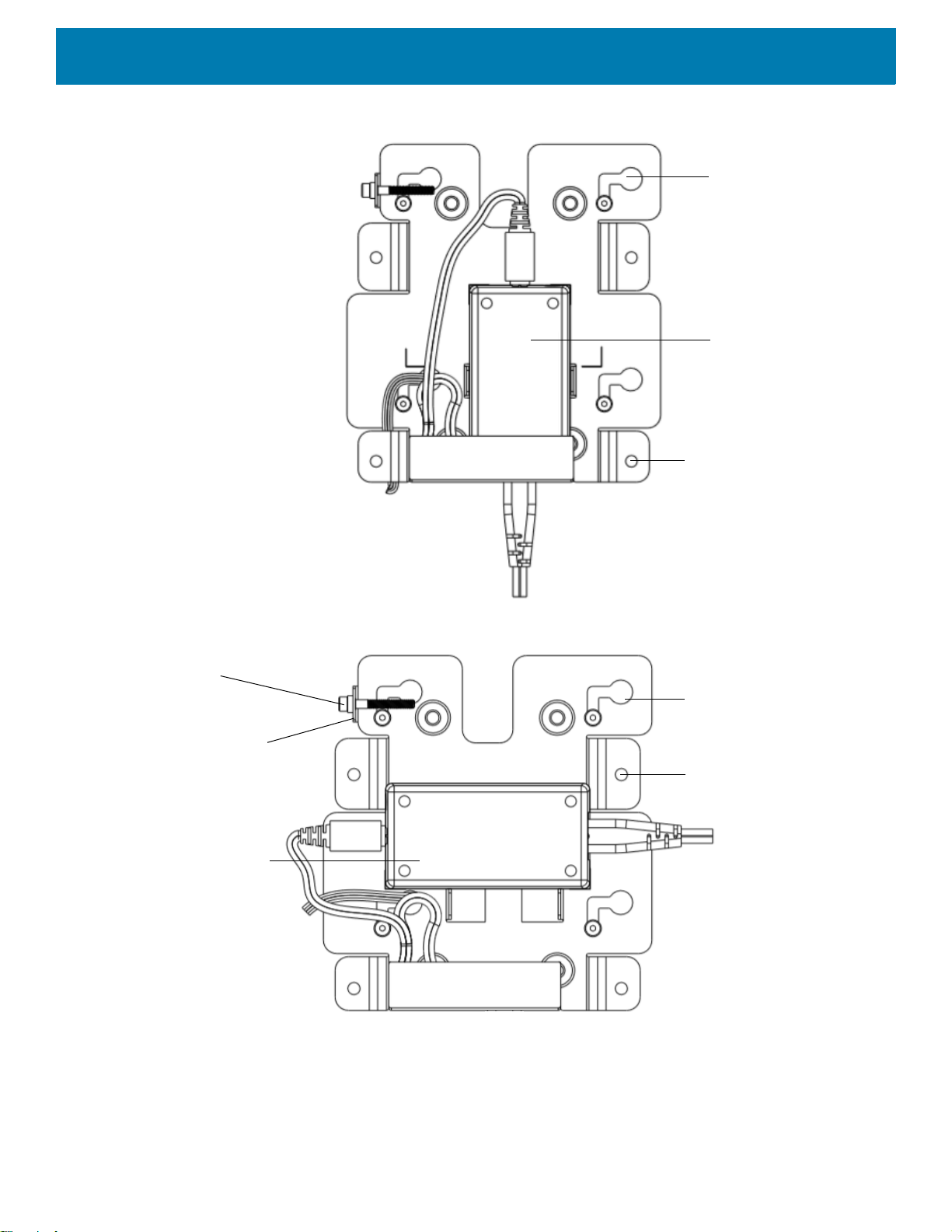
Figure 11 CC6000 Portrait Measurements
22
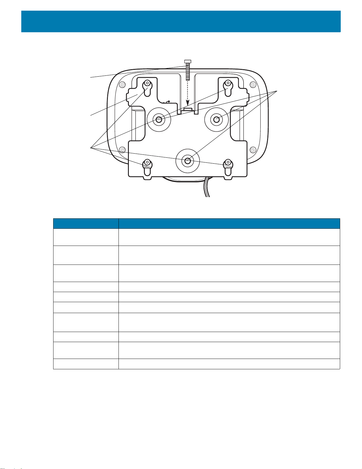
Page 23
Getting Started
Shoulder Screw Hole (4)
Wall Screw Hole (3)
Securing Screw
21
Securing Screw Hole
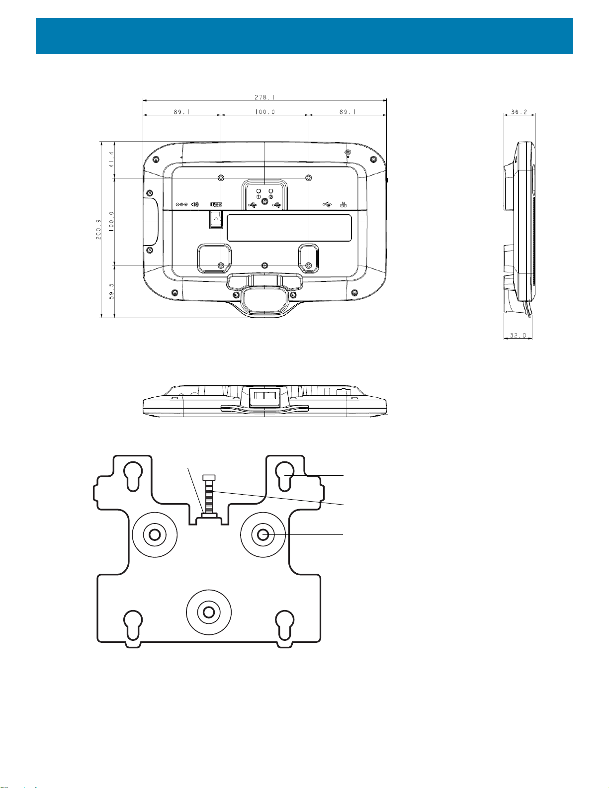
Figure 12 CC6000 Landscape Measurements
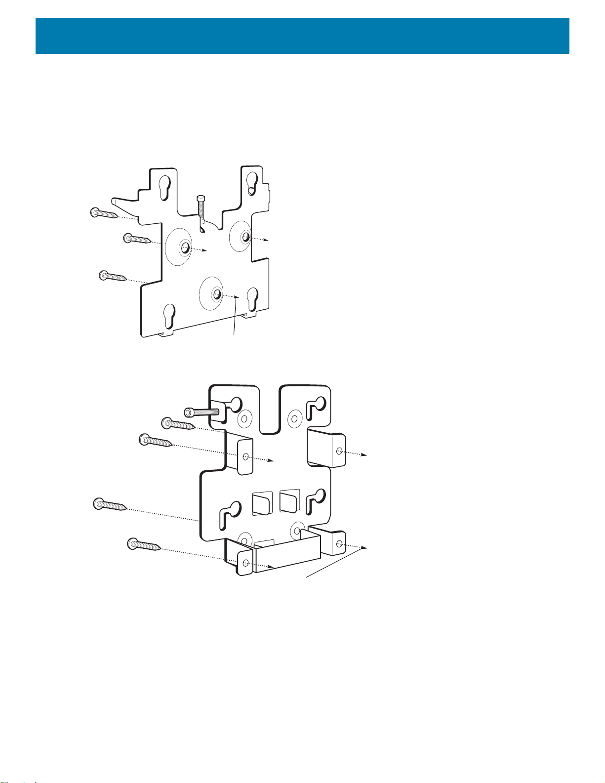
Figure 13 CC600 Mounting Bracket
23
Page 24
Getting Started
Shoulder Screw Hole (4)
Power Supply
Wall Screw Hole (4)
Shoulder Screw Hole (4)
Wall Screw Hole (4)
Securing Screw
Securing
Screw Hole
Power Supply
Figure 14 CC6000 Mounting Bracket - Portrait Orientation
Figure 15 CC6000 Mounting Bracket (KT-152098-03) - Landscape Orientation
24
Page 25
Getting Started
To Wall
To Wall
To mount the device:
1. Determine the CC600 or CC6000 mounting location.
2. Secure the mounting plate to the wall using the screws provided (three screws for the CC600 plate and four
screws for the CC6000).
Figure 16 Attaching the CC600 Bracket To Wall
Figure 17 Attaching the CC6000 Bracket To Wall
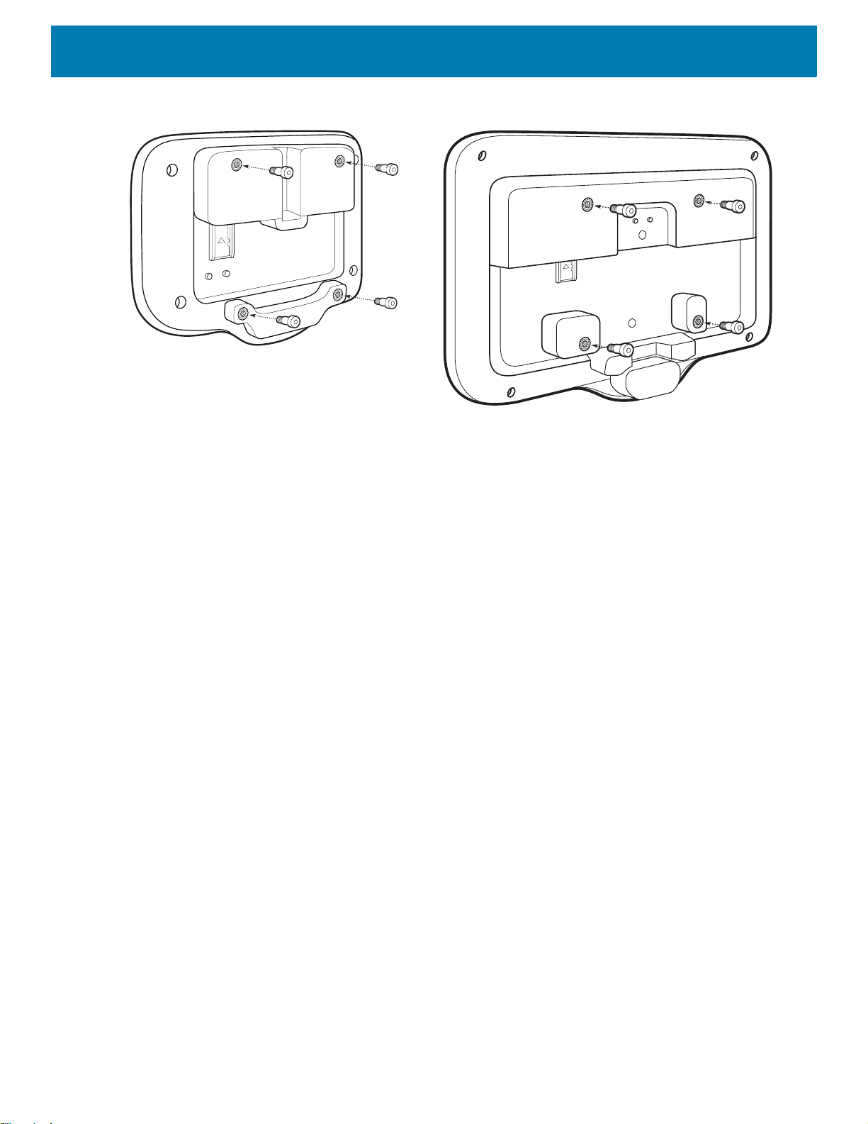
3. Insert the four shoulder screws, also provided, into the mounting holes in the back of the device.
25
Page 26
Getting Started
Figure 18 Inserting Shoulder Screws
4. Connect the power supply to the power port. Connect any additional cables into the appropriate ports
shown in Figure 3 and Figure 7.
5. Mount the device by placing the shoulder screws through the four keyholes on the mounting plate, and slide
the device down to secure in place.
26
Page 27
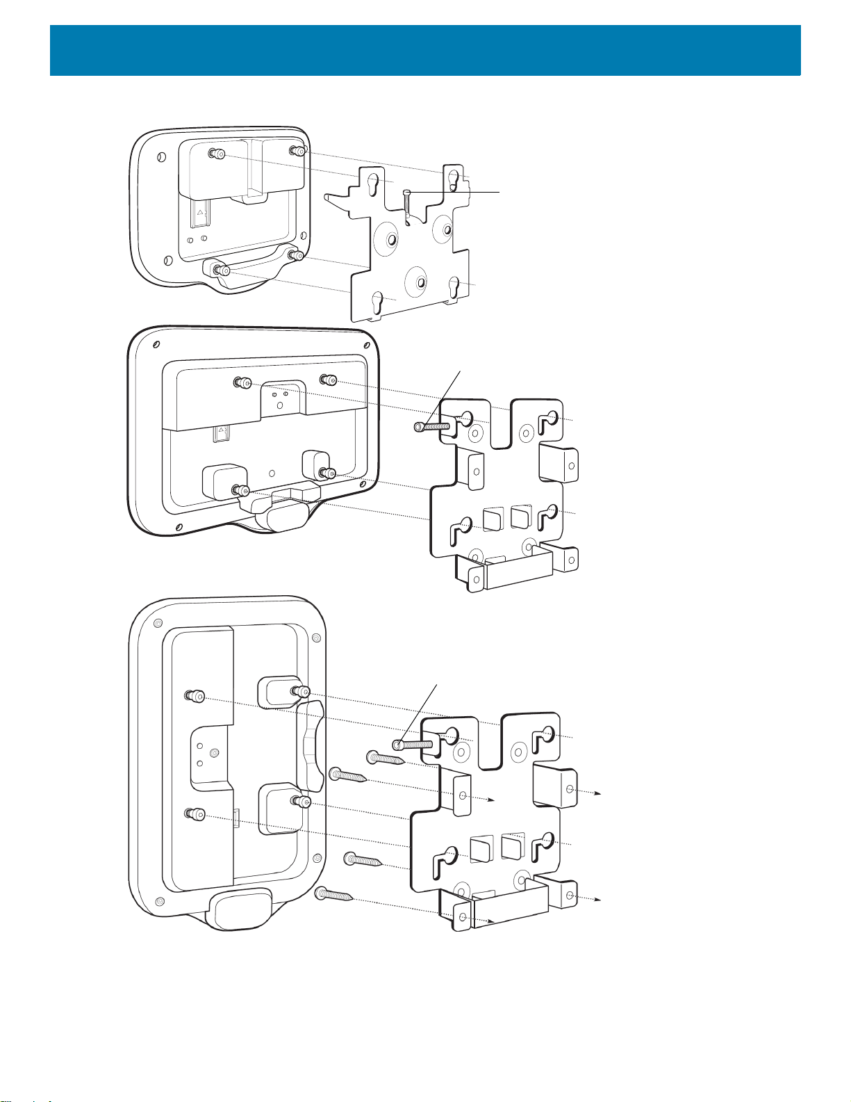
Getting Started
Locking
Screw
Locking
Screw
Locking
Screw
Figure 19 Attaching the Device to the Bracket
6. Insert the locking screw through the hole in the tab at the top of the mounting plate. Hand tighten the screw
to secure the device.
27
Page 28

Google Account Setup
NOTE: The device has to be connected to the Internet in order to set up a Google account (optional).
A Google account is only required on devices with GMS software.
The first time the device starts, the Setup Wizard displays. Follow the on-screen instructions to set up a Google
account, configure Google Wallet for purchasing items from the Play Store, to enter your personal information,
and enable backup/restore features (optional).
Zebra Visibility Services
The device captures and provides device analytics to a system administrator. The first time the device boots
(or after a Factory reset), the Zebra Services agreement screen displays.
Figure 20 Zebra Services
Getting Started
Touch the Device Data switch to disable the device from sending analytics data.
Resetting the Device
The device has a recessed reset button (see Features on page 16 for the location of the button).
To activate the reset button, use the tip of a small paper clip (1mm in diameter), insert into the recess, push
and hold for 3 seconds.
Device has a recovery console accessible via pressing the Button #1 on the back of the device upon power up
or via ADB connection and command.
The following reset functions are supported:
• Soft reset is performed with an ADB command.
• Enterprise reset (see StageNow on page 119 for more information)
• Factory reset (see StageNow on page 119 for more information)
The device recovery mode supports the following functions:
28
Page 29

Getting Started
• Flash image from zip file on an SD card or from internal flash.
• Apply a system update from an SD card or from internal flash.
29
Page 30

Settings
Introduction
This chapter describes settings available for configuring the device.
WLAN Configuration
This section provides information on configuring Wi-Fi settings.
Configuring a Secure Wi-Fi Network
To set up a Wi-Fi network:
1. Swipe from the Status bar to open the Quick Access panel and then touch .
2. Touch Network & Internet > Wi-Fi.
3. Slide the switch to the ON position.
4. The device searches for WLANs in the area and lists them on the screen.
5. Scroll through the list and select the desired WLAN network.
30
Page 31

Settings
6. Touch the desired network. If the network security is Open, the device automatically connects to the
network. For all other network security a dialog box appears.
Figure 21 WLAN WEP Network Security Dialog Box
Figure 22 WLAN 802.11 EAP Network Security Dialog Box
7. If the network security is WEP or WPA/WPS2 PSK, enter the required password and then touch Connect.
31
Page 32
8. If the network security is 802.1x EAP:
• Touch the EAP method drop-down list and select PEAP, TLS, TTLS, or LEAP.
• Touch the Phase 2 authentication drop-down list and select an authentication method.
• If required, touch CA certificate and select a Certification Authority (CA) certificate. Note: Certificates
are installed using the Security settings.
• If required, touch User certificate and select a user certificate. Note: User certificates are installed
using the Location & security settings.
• If required, in the Identity text box, enter the username credentials.
• If desired, in the Anonymous identity text box, enter an anonymous identity username.
• If required, in the Password text box, enter the password for then given identity.
NOTE: By default, the network Proxy is set to None and the IP settings is set to DHCP. See Configuring for a Proxy
Server on page 33
on page 34
9. Touch Connect.
10.Touch .
for setting the device to use a static IP address.
for setting connection to a proxy server and see Configuring the Device to Use a Static IP Address
Manually Adding a Wi-Fi Network
Settings
Manually add a Wi-Fi network if the network does not broadcast its name (SSID) or to add a Wi-Fi network
when out of range.
1. Swipe down from the Status bar to open the Quick Access panel and then touch .
2. Touch Network & Internet > Wi-Fi.
3. Slide the Wi-Fi switch to the On position.
4. Scroll to the bottom of the list and select Add network.
5. In the Network name text box, enter the name of the Wi-Fi network.
6. In the Security drop-down list, set the type of security to:
• None
•WEP
• WPA/WPA2 PSK
• 802.1x EAP.
7. If the network security is None, touch Save.
8. If the network security is WEP or WPA/WPA2 PSK, enter the required password and then touch Save.
32
Page 33

Settings
9. If the network security is 802.1x EAP:
• Touch the EAP method drop-down list and select PEAP, TLS, TTLS, PWD or LEAP.
• Touch the Phase 2 authentication drop-down list and select an authentication method.
• If required, touch CA certificate and select a Certification Authority (CA) certificate. Note: Certificates
are installed using the Security settings.
• If required, touch User certificate and select a user certificate. Note: User certificates are installed
using the Security settings.
• If required, in the Identity text box, enter the username credentials.
• If desired, in the Anonymous identity text box, enter an anonymous identity username.
• If required, in the Password text box, enter the password for the given identity.
NOTE: By default, the network Proxy is set to None and the IP settings is set to DHCP. See Configuring for a Proxy
Server on page 33
on page 34
10.Touch Save. To connect to the saved network, touch and hold on the saved network and select Connect to
network.
11.Touch .
for setting the device to use a static IP address.
for setting connection to a proxy server and see Configuring the Device to Use a Static IP Address
Configuring for a Proxy Server
A proxy server is a server that acts as an intermediary for requests from clients seeking resources from other
servers. A client connects to the proxy server and requests some service, such as a file, connection, web
page, or other resource, available from a different server. The proxy server evaluates the request according to
its filtering rules. For example, it may filter traffic by IP address or protocol. If the request is validated by the
filter, the proxy provides the resource by connecting to the relevant server and requesting the service on behalf
of the client.
It is important for enterprise customers to be able to set up secure computing environments within their
companies, making proxy configuration essential. Proxy configuration acts as a security barrier ensuring that
the proxy server monitors all traffic between the Internet and the Intranet. This is normally an integral part of
security enforcement in corporate firewalls within Intranets.
To configure the device for a proxy server:
1. In the network dialog box, touch a network.
2. Touch Advanced options.
33
Page 34
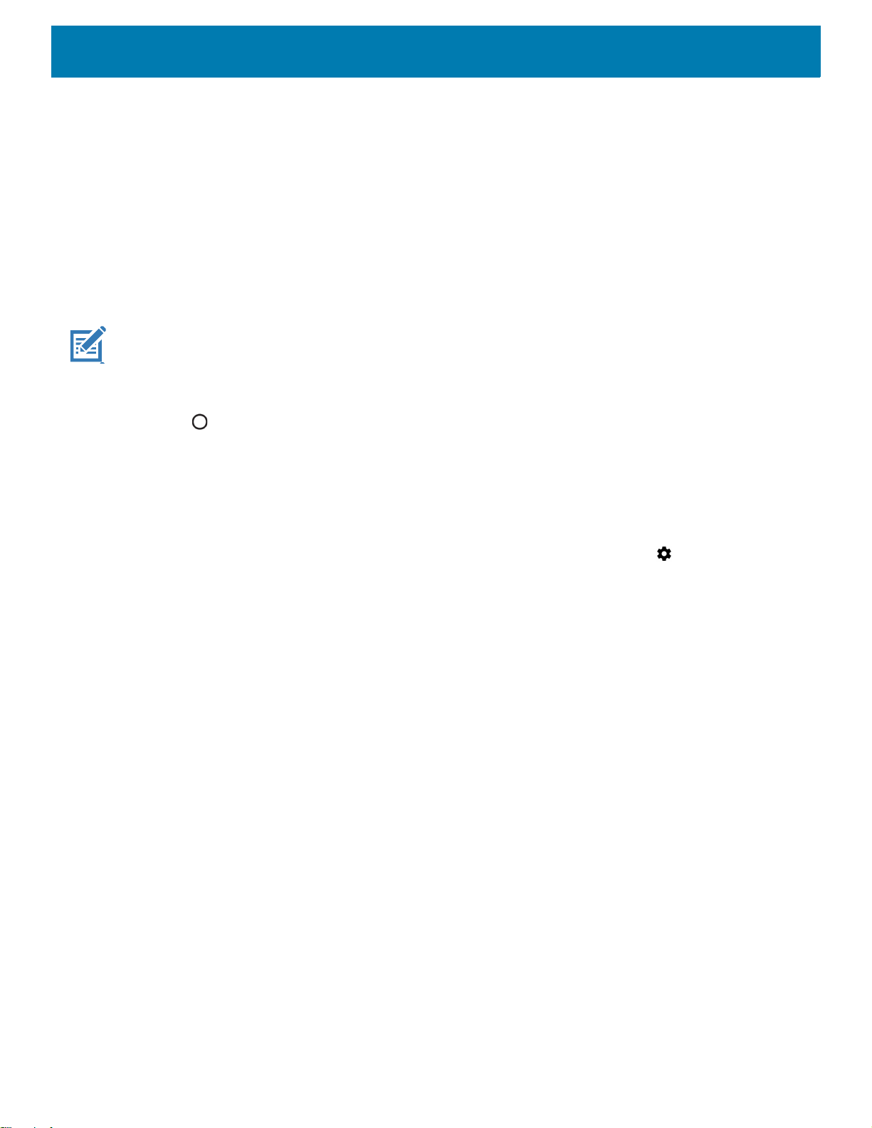
3. Touch Proxy and select Manual.
Figure 23 Proxy Settings
Settings
4. In the Proxy hostname text box, enter the address of the proxy server.
5. In the Proxy port text box, enter the port number for the proxy server.
6. In the Bypass proxy for text box, enter addresses for web sites that are not required to go through the
proxy server. Use a comma “,” between addresses. Do not use spaces or carriage returns between
addresses.
7. Touch Connect.
8. Touch .
Configuring the Device to Use a Static IP Address
By default, the device is configured to use Dynamic Host Configuration Protocol (DHCP) to assign an Internet
protocol (IP) address when connecting to a wireless network.
To configure the device to connect to a network using a static IP address:
1. In the network dialog box, touch a network.
2. Touch Advanced options.
34
Page 35
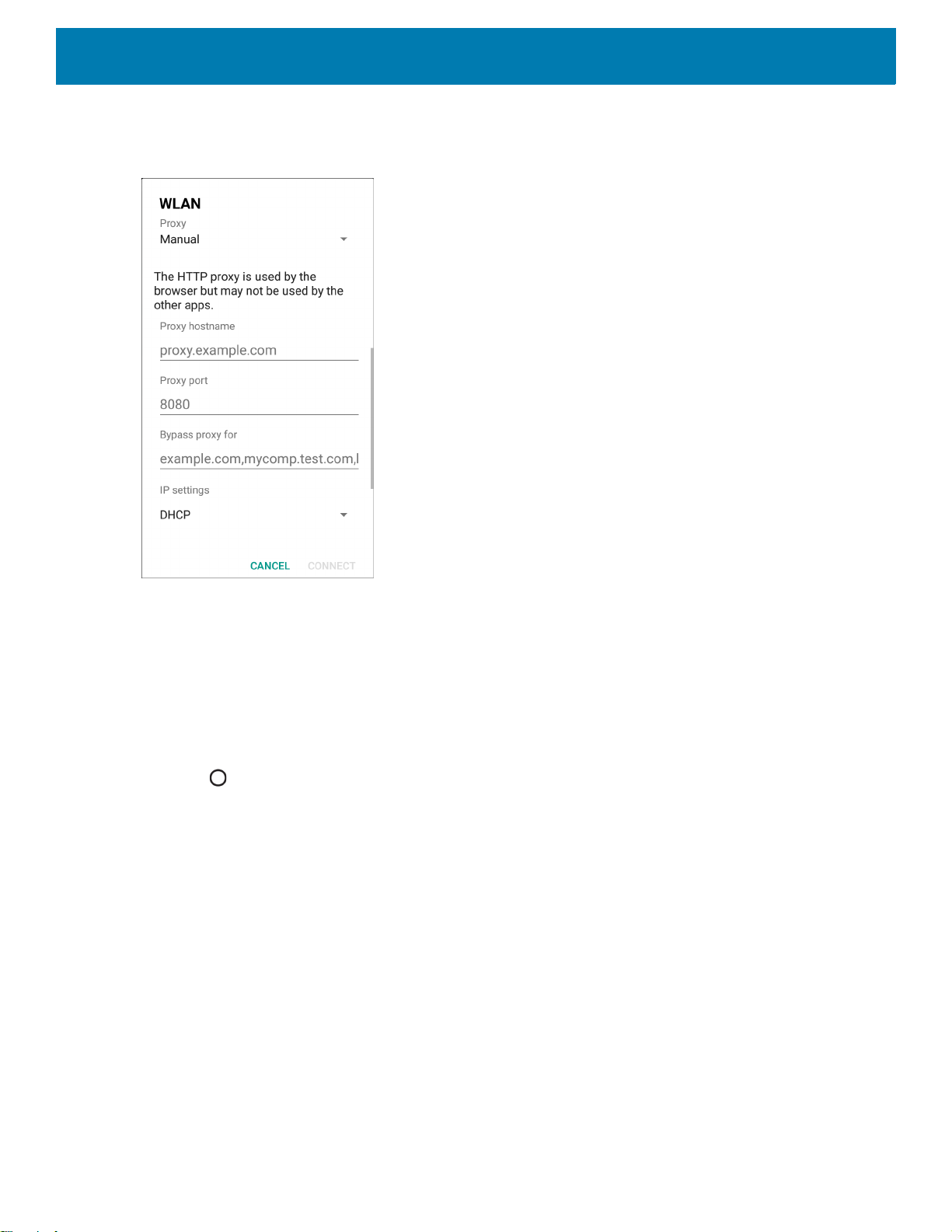
3. Touch IP settings and select Static.
Figure 24 Static IP Settings
Settings
4. In the IP address text box, enter an IP address for the device.
5. If required, in the Gateway text box, enter a gateway address for the device.
6. If required, in the Network prefix length text box, enter the prefix length.
7. If required, in the DNS 1 text box, enter a Domain Name System (DNS) address.
8. If required, in the DNS 2 text box, enter a DNS address.
9. Touch Connect.
10.Touch .
Wi-Fi Preferences
Use the Wi-Fi preferences to configure advanced Wi-Fi settings. From the Wi-Fi screen scroll down to the
bottom of the screen and touch Wi-Fi preferences.
• Open network notification - When enabled, notifies the user when an open network is available.
• Advanced - Touch to expand options.
• Additional settings - See Additional Settings.
• Install Certificates – Touch to install certificates.
• Network rating provider - Disabled (AOSP devices). To help determine what constitutes a good Wi-Fi
network, Android supports external Network rating providers that provide information about the quality of
open Wi-Fi networks. Select one of the providers listed or None. If none are available or selected, the
Connect to open networks feature is disabled.
• Wi-Fi Direct - Displays a list of devices available for a direct Wi-Fi connection.
35
Page 36

• MAC address - Displays the Media Access Control (MAC) address of the device when connecting to
Wi-Fi networks.
• IP address - Displays the IP address of the device when connecting to Wi-Fi networks.
Additional Wi-Fi Settings
NOTE: Additional Wi-Fi settings are for the device, not for a specific wireless network.
Use the Additional Settings to configure additional Wi-Fi settings. To view the additional Wi-Fi settings, scroll
to the bottom of the Wi-Fi screen and touch Wi-Fi Preferences > Advanced > Additional settings.
•Regulatory
• Country Selection - Displays the acquired country code if 802.11d is enabled, else it displays the
currently selected country code.
• Region code - Displays the current region code.
• Band and Channel Selection
• Wi-Fi frequency band - Set the frequency band to: Auto (default), 5 GHz only or 2.4 GHz only.
• Available channels (2.4 GHz) - Touch to display the Available channels menu. Select specific
channels and touch OK.
• Available channels (5 GHz) - Touch to display the Available channels menu. Select specific channels
and touch OK.
• Logging
• Advanced Logging – Touch to enable advanced logging or change the log directory.
• Wireless logs - Use to capture Wi-Fi log files.
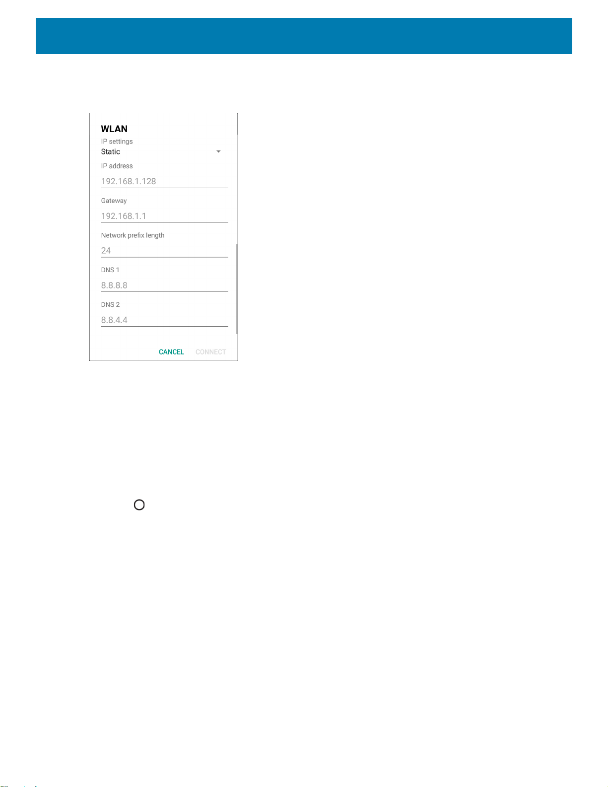
• Fusion Logger - Touch to open the Fusion Logger application. This application maintains a history
of high level WLAN events which helps to understand the status of connectivity.
• Fusion Status - Touch to display live status of WLAN state. Also provides information about the
device and connected profile.
• About
• Version - Displays the current Fusion information.
Settings
36
Page 37
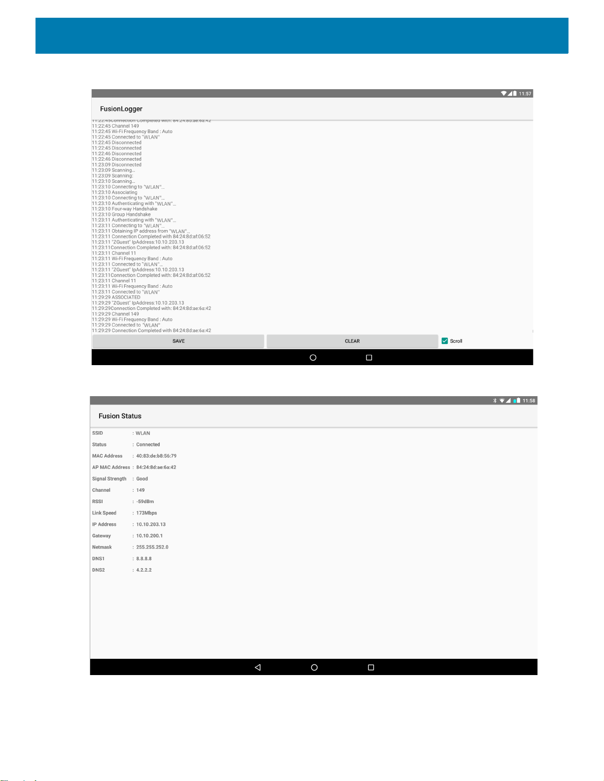
Figure 25 Fusion Logger Screen
Settings
Figure 26 Fusion Status Screen
37
Page 38
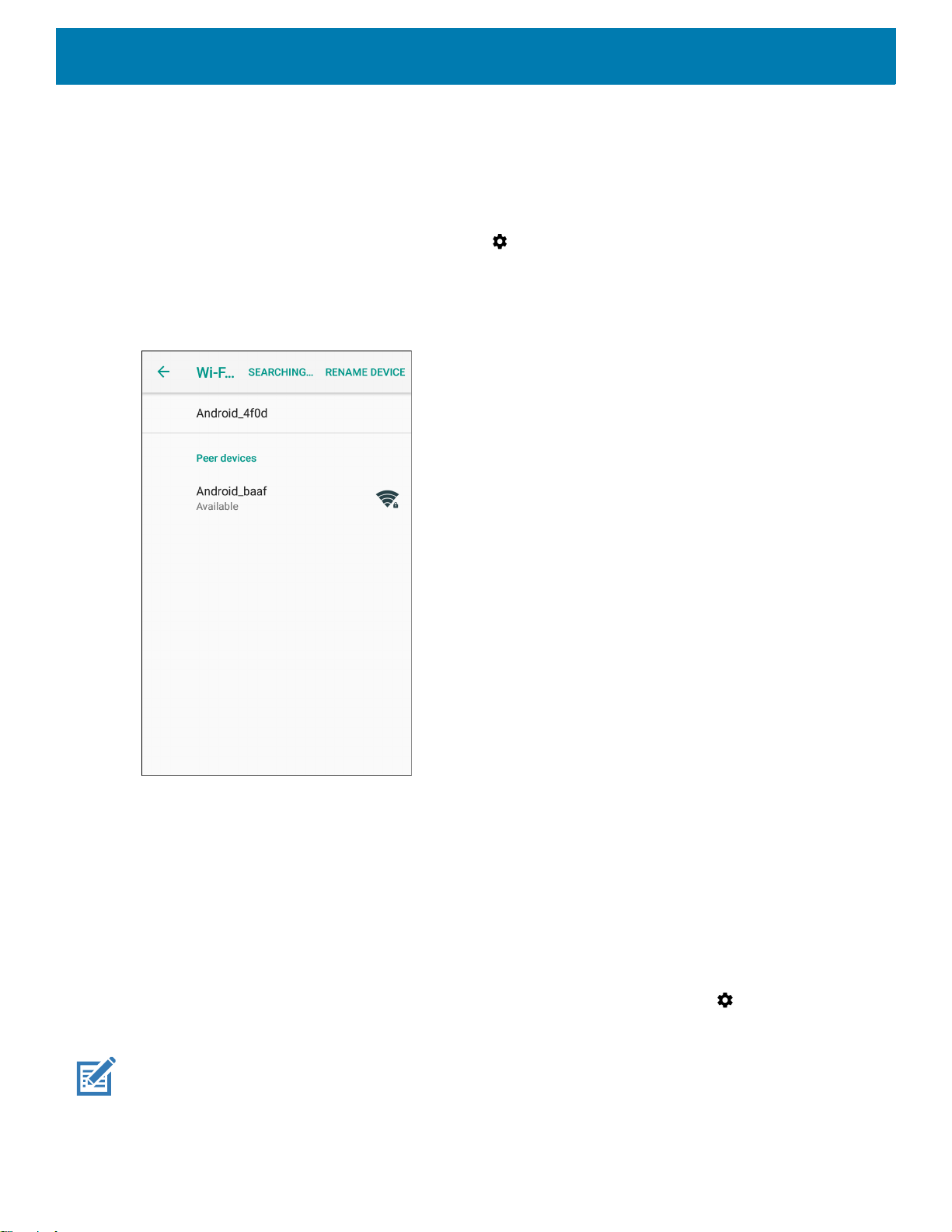
Wi-Fi Direct
Wi-Fi Direct devices can connect to each other without having to go through an access point. Wi-Fi Direct
devices establish their own ad-hoc network when required, letting you see which devices are available and
choose which one you want to connect to.
1. Swipe down from the status bar and then touch .
2. Touch Wi-Fi > Wi-Fi preferences > Advanced > Wi-Fi Direct. The device begins searching for another
Wi-Fi Direct device.
Figure 27 Wi-Fi Direct Screen
Settings
3. Under Peer devices, touch the other device name.
4. On the other device, select Accept.
5. Connected appears on the device. On both devices, in their respective Wi-Fi Direct screens, the other
device name appears in the list.
Setting Screen Lock
Use the Device security settings to set preferences for locking the screen.
1. Swipe down from the Status bar to open the Quick Access panel and then touch .
2. Touch Security & location.
NOTE: Options vary depending upon the policy of some apps, such as email.
38
Page 39

• Screen lock - Touch to configure the device to require a slide, pattern, PIN, or password to unlock the
screen.
• None - Disable screen unlock security.
• Swipe - Slide the lock icon to unlock the screen.
• Pattern - Draw a pattern to unlock screen. See Setting Screen Unlock Using Pattern on page 41 for
more information.
• PIN - Enter a numeric PIN to unlock screen. See Setting Screen Lock Using PIN on page 39 for more
information.
• Password - Enter a password to unlock screen. See Setting Screen Unlock Using Password on page
40 for more information.
Lock the screen to protect access to data on the device. Some email accounts require locking the screen. The
Locking feature functions differently in Single-user versus Multiple-user mode.
Slide the screen up to unlock. If the Pattern screen unlock feature is enabled, the Pattern screen appears
instead of the Lock screen.
If the PIN or Password screen unlock feature is enabled, enter the PIN or password after unlocking the screen.
Setting Screen Lock Using PIN
Settings
1. Swipe down from the Status bar to open the Quick Access panel and then touch .
2. Touch Security & location.
3. Touch Screen lock.
4. Touch PIN.
5. To require a PIN upon device start up select Yes, or select No not to require a PIN.
Figure 28 PIN Screen
39
Page 40
Settings
6. Touch in the text field.
7. Enter a PIN (4 numbers) then touch Next.
8. Re-enter PIN and then touch Next.
9. Select the type of notifications that appear when the screen is locked and then touch Done.
10.Touch . The next time the device goes into suspend mode a PIN is required upon waking.
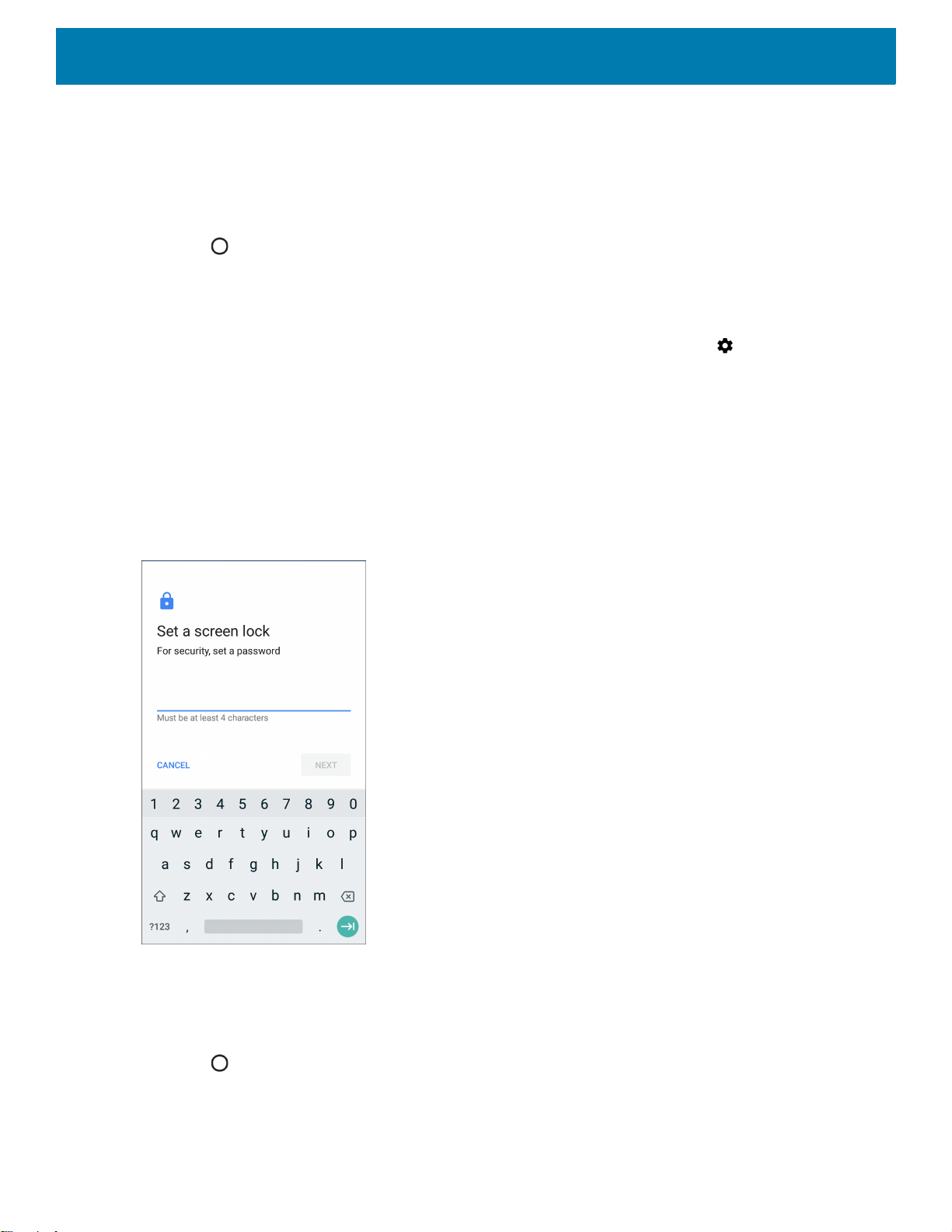
Setting Screen Unlock Using Password
1. Swipe down from the Status bar to open the Quick Access panel and then touch .
2. Touch Security & location.
3. Touch Screen lock.
4. Touch Password.
5. To require a password upon device start up select Yes, or select No not to require a password.
6. Touch in the text field.
Figure 29 Password Screen
7. Enter a password (between 4 and 16 characters) then touch Next.
8. Re-enter the password and then touch Next.
9. Select the type of notifications that appear when the screen is locked and then touch Done.
10.Touch . The next time the device goes into suspend mode a password is required upon waking.
40
Page 41

Settings
Setting Screen Unlock Using Pattern
1. Swipe down from the Status bar to open the Quick Access panel and then touch .
2. Touch Security & location.
3. Touch Screen lock.
4. Touch Pattern.
5. To require a pattern upon device start up select Yes, or select No not to require a pattern.
Figure 30 Choose Your Pattern Screen
6. Draw a pattern connecting at least four dots.
7. Touch Continue.
8. Re-draw the pattern.
9. Touch Confirm.
10.Select the type of notifications that appear when the screen is locked and then touch Done.
11.Touch . The next time the device goes into suspend mode a pattern is required upon waking.
Showing Passwords
To set the device to briefly show password characters as the user types:
1. Swipe down from the Status bar to open the Quick Access panel and then touch .
2. Touch Security & location.
3. Slide the Show passwords switch to the ON position.
41
Page 42

Accounts
Use the Accounts settings to add, remove, and manage accounts. Use these settings to control how
applications send, receive, and sync data on their own schedules, and whether applications can synchronize
user data automatically.
Applications may also have their own settings to control how they synchronize data; see the documentation for
those applications for details.
Language Usage
Use the Language & input settings to change the device’s language, including words added to the dictionary.
Changing the Language Setting
1. Swipe down from the Status bar to open the Quick Access panel and then touch .
2. Touch System > Languages & input.
3. Touch Languages. A list of available languages displays.
Settings
4. If the desired language is not listed, touch Add a language and select a language from the list.
5. Touch and hold to the right of the desired language, then drag it to the top of the list.
6. The operating system text changes to the selected language.
Adding Words to the Dictionary
1. Swipe down from the Status bar to open the Quick Access panel and then touch .
2. Touch System > Languages & input > Advanced > Personal dictionary.
3. If prompted, select the language where this word or phase is stored.
4. Touch + to add a new word or phrase to the dictionary.
5. Enter the word or phrase.
6. In the Shortcut text box, enter a shortcut for the word or phrase.
7. Touch .
Keyboard Settings
Use the Languages & input settings to configure the on-screen keyboards. The device contains the following
keyboard settings:
• Android Keyboard - AOSP devices only
• Enterprise Keyboard
• Gboard - GMS devices only.
42
Page 43

PTT Express Configuration
Refer to the PTT Express User Guide at www.zebra.com/support for information on configuring the PTT
Express Client application.
RxLogger
RxLogger is a comprehensive diagnostic tool that provides application and system metrics, allows for the
creation of custom plug-ins, and diagnoses device and application issues. RxLogger logs the following
information: CPU load, memory load, memory snapshots, power states, wireless logging, cellular logging, TCP
dumps, Bluetooth logging, GPS logging, logcat, FTP push/pull, ANR dumps, etc. All generated logs and files
are saved onto flash storage on the device (internal or external).
Figure 31 RxLogger
Settings
RxLogger Configuration
RxLogger is built with an extensible plug-in architecture and comes packaged with a number of plug-ins
already built-in. The included plug-ins are described below.
43
Page 44

Settings
To open the configuration screen, from the RxLogger home screen touch Settings.
Figure 32 RxLogger Configuration Screen
RxLogger Settings
The RxLogger Settings module provides additional RxLogger settings.
• Enable notifications - Select to allow RxLogger notifications in the Status bar and Notification panel.
• Enable debug logs - Select to enable debug logs.
ANR Module
Application Not Responsive (ANR) indicates that a running application’s UI thread is not responding for a
specified time period. RxLogger is able to detect this condition and trigger a copy of the call stack trace of the
unresponsive application into the log directory. The event is also indicated in the high level CSV log.
• Enable Module - Enables logging for this module.
• Log path - Specifies the default log path to store the ANR log files.
• Collect Historic ANRs - Collects ANR trace files from the system.
Kernal Module
The Kernel Module captures kmsg from the system.
• Enable Module - Enables logging for this kernal module.
• Log path - Specifies the high level log path for storage of all kernal logs. This setting applies globally to all
kernal buffers.
• Kernal Log filename - Specifies the base log filename for this kernal buffer. The current file count is
appended to this name.
• Max Kernal log file size - Specifies the maximum size, in megabytes, of an individual log file.
• Kernal Log interval - Sets the interval, in seconds, on which to flush the log buffer to the file.
44
Page 45

Settings
• Kernal Log file count - Specifies the number of log files to keep and rotate through. Each log file is subject
to the max log size option.
• Enable System Timestamp in Kernal Log - Enables system timestamps in kernal logs.
• System Timestamp Interval - Sets the interval, in seconds, between system timestamps.
• Enable Logcat Integration override - Enables logcat integration overrides.
Logcat Module
Logcat is an essential debugging tool on Android devices. RxLogger provides the ability to record data from all
four of the available logcat buffers. The Logcat plug-in can collect data from multiple logcat buffers provided by
the system, which are the main, event, radio, and system buffers. Each of the settings are available for each
buffer independently unless otherwise noted.
• Enable Module - Enables logging for this module.
• Log path - Specifies the high level log path for storage of all logcat logs. This setting applies globally to all
logcat buffers.
• Enable main logcat - Enables logging for this logcat buffer.
• Main Log interval (sec) - Sets the interval, in seconds, on which to flush the log buffer to the file.
• Main Log filename - Specifies the base log filename for this logcat buffer. The current file count is
appended to this name.
• Main Log file count - Specifies the number of log files to keep and rotate through. Each log file is
subject to the max log size option.
• Main log file size (MB) - Specifies the maximum size, in megabytes, of an individual log file.
• Main log filter - Custom logcat filter to run on the main buffer.
• Enable event logcat - Enables event logging for this logcat buffer.
• Event log interval (sec) - Sets the interval, in seconds, on which to flush the log buffer to the file.
• Event log filename - Specifies the base log filename for this logcat buffer. The current file count is
appended to this name.
• Event log file count - Specifies the number of log files to keep and rotate through. Each log file is
subject to the max log size option.
• Event log file size (MB) - Specifies the maximum size, in kilobytes, of an individual log file.
• Event log filter - Custom logcat filter to run on the event buffer.
• Enable radio logcat - Enables logging for this logcat buffer.
• Radio log interval (sec) - Sets the interval, in seconds, on which to flush the log buffer to the file.
• Radio log filename - Specifies the base log filename for this logcat buffer. The current file count is
appended to this name.
• Radio log file count - Specifies the number of log files to keep and rotate through
subject to the max log size option.
• Radio log file size (MB) - Specifies the maximum size, in kilobytes, of an individual log file.
• Radio log filter -Custom logcat filter to run on the radio buffer.
. Each log file is
45
Page 46

Settings
• Enable system logcat - Enables logging for this logcat buffer.
• System log interval (sec) - Sets the interval, in seconds, on which to flush the log buffer to the file.
• System log filename - Specifies the base log filename for this logcat buffer. The current file count is
appended to this name.
• System log file count - Specifies the number of log files to keep and rotate through. Each log file is
subject to the max log size option.
• System log file size (MB) - Specifies the maximum size, in kilobytes, of an individual log file.
• System log filter - Custom logcat filter to run on the system buffer.
• Enable crash logcat- Enables logging for this crash logcat buffer.
• Crash log interval (sec) - Sets the interval, in seconds, on which to flush the log buffer to the file.
• Crash log filename - Specifies the base log filename for this logcat buffer. The current file count is
appended to this name.
• Crash log file count - Specifies the number of log files to keep and rotate through. Each log file is
subject to the max log size option.
• Crash log file size (MB) - Specifies the maximum size, in megabytes, of an individual log file.
• Crash log filter - Custom logcat filter to run on the crash buffer.
• Enable combined logcat - Enables logging for this logcat buffer.
• Enable main buffer - Enable or disable the addition of the main buffer into the combined logcat file.
• Enable event buffer - Enable or disable the addition of the event buffer into the combined logcat file.
• Enable radio buffer - Enable or disable the addition of the radio buffer into the combined logcat file.
• Enable system buffer - Enable or disable the addition of the system buffer into the combined logcat file.
• Enable crash buffer - Enable or disable the addition of the crash buffer into the combined logcat file.
• Combine log interval (sec) - Sets the interval, in seconds, on which to flush the log buffer to the file.
• Combined log filename - Specifies the base log filename for this logcat buffer. The current file count is
appended to this name.
• Combined log file count - Specifies the number of log files to keep and rotate through. Each log file is
subject to the max log size option.
• Combined log file size (MB) - Specifies the maximum size, in megabytes, of an individual log file.
• Combined log filter - Custom logcat filter to run on the combined buffer.
LTS Module
The LTS (Long Term Storage) Module captures data over a long duration of time without losing any data.
Whenever a file is done being written, LTS saves it as a GZ file in an organized path for later use.
• Enable Module - Enables logging for this module.
• Storage Directory - Specifies the high level log path for storage of all logcat logs. This setting applies
globally to all logcat buffers.
Ramoops Module
The Ramoops Module captures the last kmsg from the device.
• Enable Module - Enables logging for this module.
• Log path - Specifies the high level log path for storage of all ramoops logs. This setting applies globally to
all Ramoops buffers.
• Base filename - Specifies the base log filename for this kernal buffer. The current file count is appended to
this name.
46
Page 47

Settings
• Ramoops file count - Specifies the number of log files to keep and rotate through. Each log file is subject
to the log size option.
Resource Module
The Resource Module captures device information and system statistics at specified intervals. The data is
used to determine the health of the device over a period of time.
• Enable Module - Enables logging for this module.
• Log Path - Specifies the high level log path for storage of all resource logs. This setting applies globally to
all resource buffers.
• Resource Log interval - Sets the interval, in seconds, on which to flush the log buffer to the file.
• Resource Log file size - Specifies the maximum size, in megabytes, of an individual log file.
• Resource Log file count - Specifies the number of log files to keep and rotate through. Each log file is
subject to the max log size option.
• System Resource- Enables or disables the collection of System Resource information.
• Network - Enables or disables the collection of Network status.
• Bluetooth - Enables or disables the collection of Bluetooth information.
• Light - Enables or disables the collection of ambient light level.
• Heater - Not supported.
Snapshot Module
The Snapshot Module collects detailed device statistics at an interval to see detailed device information.
• Enable Module - Enables logging for this module.
• Log Path - Specifies the base path to use to store the snapshot files
• Log filename - Specifies the base filename for all the snapshot files. The current file count is appended to
this name.
• Log Interval (sec) - Specifies the interval, in seconds, on which to invoke a detailed snapshot.
• Snapshot file count - The maximum number of Snapshot files to keep at any one time.
• Top - Enables or disables the running of the
• CPU Info - Enables detailed per process CPU logging in the snapshot.
• Memory Info - Enables logging of detailed per process memory usage in the snapshot.
• Wake Locks - Enables or disables the collection of the sys/fs wake_lock information.
• Time in State - Enables or disables the collection of the sys/fs cpufreq for each core.
• Processes - Enables dumping the complete process list in the snapshot.
• Threads - Enables dumping all processes and their threads in the snapshot.
• Properties - Enables dumping of all system properties on the device. This includes build/version
information as well as state information.
• Interfaces - Enables or disables the running of the
top command for data collection.
netcfg command for data collection.
• IP Routing Table - Enables or disables the collection of the net route for data collection.
• Connectivity - Enables or disables the running of the
• Wifi - Enables or disables the running of the
• File systems - Enables dumping of the available volumes on the file system and the free storage space for
each.
dumpsys wifi command for data collection.
dumpsys connectivity command for data collection.
47
Page 48

Settings
• Usage stats - Enables dumping of detailed usage information for each package on the device. This
includes the number of starts and duration of each run.
TCPDump Module
The TCPDump Module captures TCP data that happens over the device’s networks.
• Enable Module - Enables logging for this module.
• Log path - Specifies the location to store the TCPDump output log files.
• Base filename - Specifies the base filename to use when storing the TCPDump files. The index number of
the current log file is appended to the filename.
• Tcpdump file size (MB) - Specifies the maximum file size, in megabytes, for each log file created.
• Tcpdump file count - Specifies the number of log files to cycle through when storing the network traces.
Tombstone Module
The Tombstone Module collects tombstone (Linux Native Crashes) logs from the device.
• Enable Module - Enables logging for this module.
• Log path - Specifies the location to store the Tombstone output log files.
• Collect Historic tombstones - Collects new and existing tombstone files.
Configuration File
RxLogger configuration can be set using an XML file. The config.xml configuration file is located on the
microSD card in the
connection. Edit the configuration file and then replace the XML file on the device. There is no need to stop and
restart the RxLogger service since the file change is automatically detected.
Enabling Logging
To enable logging:
1. Swipe the screen up and select .
2. Touch Start.
3. Touch .
Disabling Logging
To disable logging:
1. Swipe the screen up and select .
2. Touch Stop.
RxLogger\config folder. Copy the file from the device to a host computer using a USB
3. Touch .
Extracting Log Files
1. Connect the device to a host computer using an USB connection.
48
Page 49
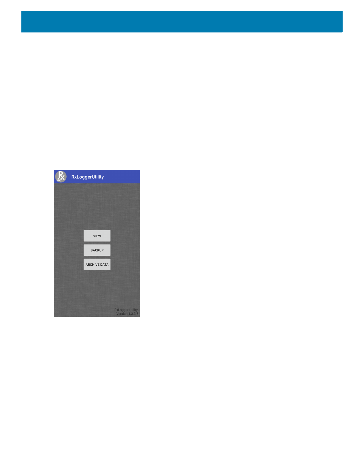
2. Using a file explorer, navigate to the RxLogger folder.
3. Copy the file from the device to the host computer.
4. Disconnect the device from the host computer.
RxLogger Utility
RxLogger Utility is a data monitoring application for viewing logs in the device while RxLogger is running. Logs
and RxLogger Utility features are accessed in the App View or the Overlay View.
App View
In App View, the user views logs in the RxLogger Utility.
Figure 33 App View
Settings
49
Page 50
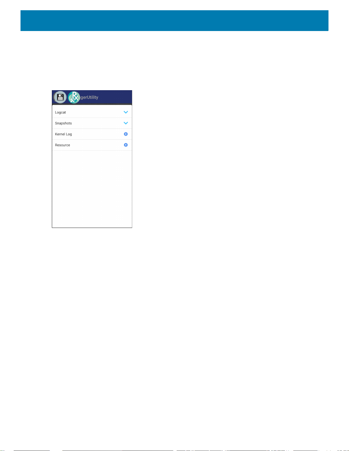
Settings
Viewing Logs
To view logs:
1. Touch the Main Chat Head icon. The Overlay View screen appears.
Figure 34 Overlay View Screen
2. Touch a log to open it. The user can open many logs with each displaying a new sub Chat Head.
3. If necessary, scroll left or right to view additional Sub Chat Head icons.
50
Page 51
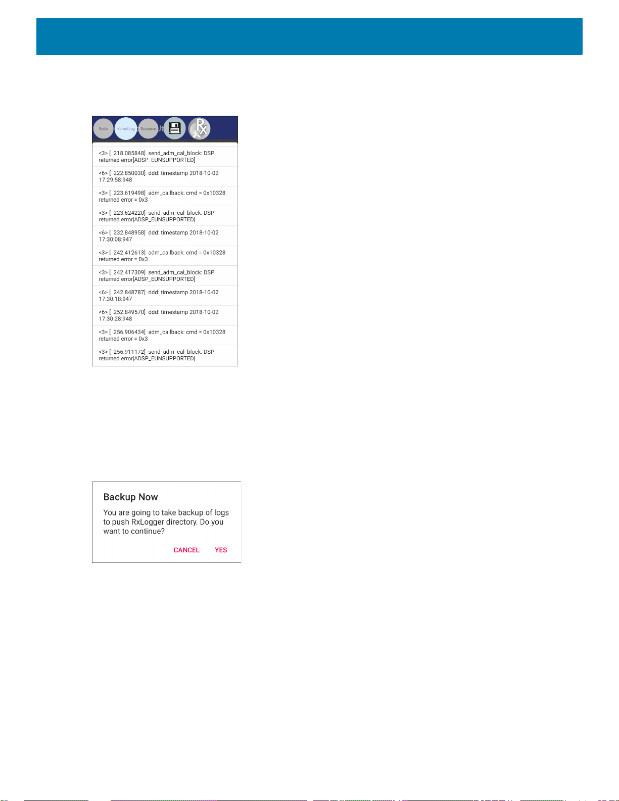
Settings
4. Touch a Sub Chat Head to display the log contents.
Figure 35 Log File
Backup
RxLogger Utility allows the user to make a zip file of the RxLogger folder in the device, which by default
contains all the RxLogger logs stored in the device.
To save the backup data, touch BACKUP > Yes.
Figure 36 Backup Message
51
Page 52
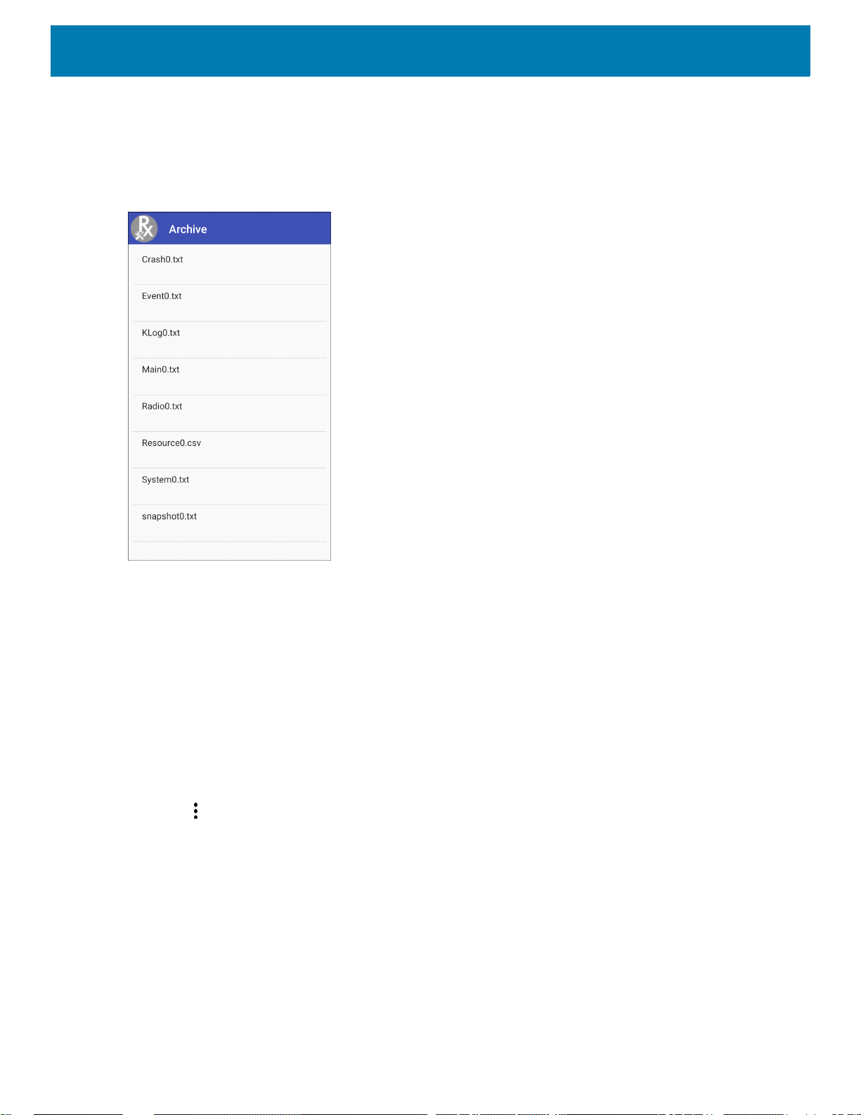
Settings
Archive Data
View all the RxLogger logs stored in the default RxLogger directory. Logs viewed in the Archive window are not
live.
Figure 37 Archive
To view the log files, touch ARCHIVE DATA and then touch a log file.
Overlay View
Use Overlay View to display RxLogger information while using other apps or on the home screen. Overlay
View is accessed using the Main Chat Head.
Initiating the Main Chat Head
To initiate the Main Chat Head:
1. Open RxLogger.
2. Touch > Toggle Chat Head. The Main Chat Head icon appears on the screen.
3. Touch and drag the Main Chat head icon to move it around the screen.
Removing the Main Chat Head
To remove the Main Chat Head icon:
1. Touch and drag the icon. A circle with an X appears.
2. Move the icon over the circle and then release.
52
Page 53

Settings
Viewing Logs
To view logs:
1. Touch the Main Chat Head icon. The Overlay View screen appears.
Figure 38 Overlay View Screen
2. Touch a log to open it. The user can open many logs with each displaying a new sub Chat Head.
3. If necessary, scroll left or right to view additional Sub Chat Head icons.
53
Page 54
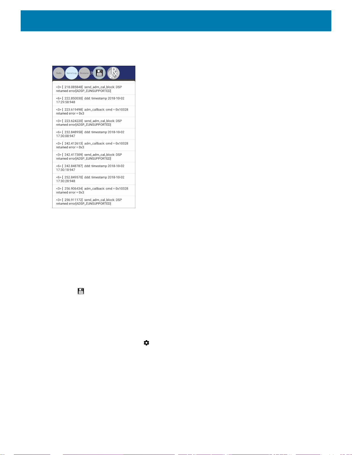
Settings
4. Touch a Sub Chat Head to display the log contents.
Figure 39 Log File
Removing a Sub Chat Head Icon
To remove a sub chat Head icon, press and hold the icon until it disappears.
Backing Up In Overlay View
RxLogger Utility allows the user to make a zip file of the RxLogger folder in the device, which by default
contains all the RxLogger logs stored in the device.
The Backup icon is always available in Overlay View.
1. Touch . The Backup dialog box appears.
2. Touch Yes to create the back up.
About Phone
Use About phone settings to view information about the device. Swipe down from the Status bar to open the
Quick Access panel and then touch > System > About phone.
• Status - Touch to display the following:
• IP address - Displays the IP address of the device.
• Wi-Fi MAC address - Displays the Wi-Fi radio MAC address.
• Ethernet MAC address - Displays the Ethernet driver MAC address.
• Bluetooth address - Displays the Bluetooth radio Bluetooth address.
• Serial number - Displays the serial number of the device.
• MSM serial number - Displays the serial number of the MSM.
• Up time - Displays the time that the device has been running since being turned on.
54
Page 55

Settings
• SW components - Lists filenames and versions for various software on the device.
•Audio
• Acoustics
•MX
• Hardware ID
•NFC
• Scanner
•Touch
• Build Date
• Device Update Version
• Baseline
• Secure Boot Status
• ABL ARB Version
• Remaining Reboot Count to Lock
• Legal information - Opens a screen to view legal information about the software included on the device.
• Third-party Licenses
• Google Legal
• System WebView Licenses
• Wallpapers
•Zebra EULA
• Model - Displays the devices model number.
• Android version - Displays the operating system version.
• Android security patch level - Displays the security patch level date.
• Baseband version - Displays WAN radio firmware version (WWAN only).
• Kernel version - Displays the kernel version.
• Build Fingerprint - Defines Device Manufacturer, Model, Android version and Build version together in one
location.
• Build number - Displays the software build number.
55
Page 56

USB/Ethernet Communication
Introduction
This chapter describes the use and configurations of the USB ports and the Ethernet connection.
The CC6000 includes two USB-2 ports for external peripherals, and one USB-C that can be used for
OTG or an external monitor.
The CC600 includes one USB-C that can be used as an OTG port or to connect to an external monitor
or USB peripherals (which can be connected simultaneously using a splitter).
Transferring Files with a Host Computer via USB
Connect the device to a host computer using a USB cable to transfer files between the device and the
host computer.
When connecting the device to a host computer, follow the host computer’s instructions for connecting
and disconnecting USB devices, to avoid damaging or corrupting files.
Transferring Files
NOTE: Use Transfer files to copy files between the device (internal memory or microSD card) and the host
computer.
1. Connect a USB cable to the device.
56
Page 57
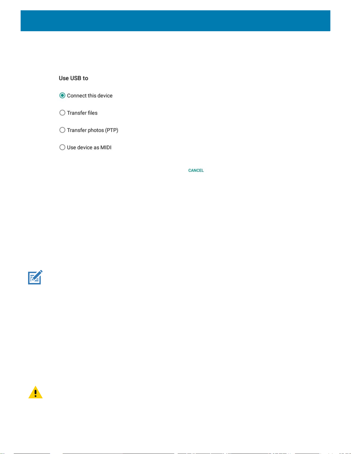
USB/Ethernet Communication
2. Pull down the Notification panel and touch USB connect this device.
By default, Connect this device is selected.
Figure 40 Use USB to Dialog Box
3. Touch Transfer files.
4. On the host computer, open a file explorer application.
5. Locate the device as a portable device.
6. Open the SD card or the Internal storage folder.
7. Copy files to and from the device or delete files as required.
Transferring Photos
To transfer photos using Photo Transfer Protocol:
NOTE: Use Photo Transfer Protocol (PTP) to copy photos from either the microSD card or internal memory to the host com-
puter.
1. Connect USB cable to the device. (See Features on page 16 for communication ports.)
2. Pull down the Notification panel and touch USB connect this device.
3. Touch Transfer photos (PTP).
4. On the host computer, open a file explorer application.
5. Open the SD card or the Internal storage folder.
6. Copy or delete photos as required.
Disconnect from the Host Computer
To disconnect the device from the host computer:
CAUTION: Carefully follow the host computer’s instructions to unmount the microSD card and disconnect USB devices cor-
rectly to avoid losing information.
1. On the host computer, unmount the device.
2. Remove the USB cable from the device.
57
Page 58

USB/Ethernet Communication
USB/Ethernet Communication
For POE (Ethernet) communication, connect an Ethernet cable to the port.
For USB communication, connect a USB cable to the port.
Ethernet Settings
The following settings can be configured when using Ethernet communication:
• Proxy Settings
• Static IP.
Configuring Ethernet Proxy Settings
~
NOTE: Ethernet is on is the default for the device.
To configure the Ethernet connection:
1. Connect one end of the Ethernet cable to the POE port on the device.
2. Connect the other end to an active Ethernet jack or hub.
3. Swipe down with two fingers from the status bar to open the quick access panel and then touch .
4. Touch Network & Internet.
5. Touch Ethernet.
6. Slide the switch to the ON position.
7. Touch and hold Eth0 until the menu appears.
8. Touch Modify Proxy.
9. Touch the Proxy drop-down list and select Manual.
Figure 41 Ethernet Proxy Settings
58
Page 59

USB/Ethernet Communication
10.In the Proxy hostname field, enter the proxy server address.
11.In the Proxy port field, enter the proxy server port number.
NOTE: When entering proxy addresses in the Bypass proxy for field, do not use spaces or carriage returns between
addresses.
12.In the Bypass proxy for text box, enter addresses for web sites that do not require to go through the proxy
server. Use the separator “|” between addresses.
13.Touch MODIFY.
14.Touch .
Configuring Ethernet Static IP Address
To configure the Ethernet Static IP Address:
1. Swipe down with two fingers from the status bar to open the quick access panel and then touch .
2. Touch Network & Internet.
3. Touch Ethernet.
4. Slide the switch to the ON position.
5. Touch Eth0.
6. Touch the IP settings drop-down list and select Static.
Figure 42 Static IP Settings
7. In the IP address field, enter the proxy server address.
8. If required, in the Gateway field, enter a gateway address for the device.
59
Page 60

USB/Ethernet Communication
9. If required, in the Netmask field, enter the network mask address
10.If required, in the DNS address fields, enter a Domain Name System (DNS) addresses.
11.Touch CONNECT.
12.Touch .
Establishing Ethernet Connection
1. Swipe down with two fingers from the status bar to open the quick access panel and then touch .
2. Touch Network & Internet.
3. Touch Ethernet.
4. Insert the device into a slot.
5. Slide the Ethernet switch to the ON position.
The icon appears in the Status bar.
6. Touch Eth0 to view Ethernet connection details.
60
Page 61

DataWedge
Introduction
This chapter applies to DataWedge on Android devices. DataWedge is an application that reads data,
processes the data and sends the data to an application.
Basic Scanning
Scanning can be performed using the CC600 and CC6000 Customer Concierge or an imager such as
the DS22X8 or DS81X8.
Barcode Capture with an Imager
To capture barcode data with the CC600/CC6000 Customer Concierge:
1. Ensure that an application is open on the device and a text field is in focus (text cursor in text field).
2. Place the barcode in the field of view of the device’s scan window. Ensure the barcode is within the
scanner’s aiming pattern.
3. The LEDs light green and a beep sounds, by default, to indicate the barcode was decoded
successfully. Note that when the device is in Pick List Mode, the device does not decode the
barcode until the center of the illuminated line or dot touches the barcode.
To capture barcode data with the DS22X8 or DS81X8 imager:
1. Ensure that an application is open on the device and a text field is in focus (text cursor in text field).
2. Press and hold the trigger until either:
a. The imaging scanner reads the bar code. The imaging scanner beeps, the LED flashes, and the
scan line turns off.
or
b. The imaging scanner does not read the bar code and the scan line turns off.
Note that when the device is in Pick List Mode, the device does not decode the barcode until the
center of the illuminated line or dot touches the barcode.
61
Page 62

Profiles
DataWedge
Figure 43 Aiming Pattern on Bar Code - DS22X8 and DS81X8
.
3. Release the trigger.
4. The barcode content data appears in the text field.
DataWedge is based on profiles and plug-ins. A profile contains information on how DataWedge should
behave with different applications.
Profile information consists of:
• Associated application
• Data Capture Plus configurations
• Input plug-in configurations
• Output plug-in configurations
• Process plug-in configurations.
Using profiles, each application can have a specific DataWedge configuration. For example, each user
application can have a profile which outputs scanned data in the required format when that application comes
to the foreground. DataWedge can be configured to process the same set of captured data differently based on
the requirements of each application.
DataWedge includes the following pre-configured profiles which support specific built-in applications:
• Visible profiles:
• Profile0 - created automatically the first time DataWedge runs. Generic profile used when there are no
user created profiles associated with an application.
• Launcher - enables scanning when the Launcher is in foreground.
• DWDemo - provides support for the DWDemo application.
Some Zebra applications are capable of capturing data by scanning. DataWedge is pre-loaded with private
and hidden profiles for this purpose. There is no option to modify the private profiles.
Profile0
Profile0 can be edited but cannot be associated with an application. That is, DataWedge allows manipulation
of plug-in settings for Profile0 but it does not allow assignment of a foreground application. This configuration
allows DataWedge to send output data to any foreground application other than applications associated with
user-defined profiles when Profile0 is enabled.
62
Page 63

Profile0 can be disabled to allow DataWedge to only send output data to those applications which are
associated in user-defined profiles. For example, create a profile associating a specific application, disable
Profile0 and then scan. DataWedge only sends data to the application specified in the user-created profile.
This adds additional security to DataWedge enabling the sending of data only to specified applications.
Plug-ins
A plug-in is a software module utilized in DataWedge to extend its functionality to encompass technologies
such as barcode scanning. The plug-ins can be categorized into three types based on their operations:
• Input Plug-ins
• Output Plug-ins
• Process Plug-ins.
Input Plug-ins
An Input Plug-in supports an input device, such as a barcode scanner contained in, or attached to the device.
DataWedge contains base plug-ins for these input devices.
DataWedge
IMPORTANT: Barcode Scanner Input Plug-in – The Barcode Scanner Input Plug-in is responsible for reading
data from the integrated barcode scanner and supports different types of barcode readers including laser,
imager and internal camera. Raw data read from the barcode scanner can be processed or formatted using
Process Plug-ins as required. DataWedge has built-in feedback functionality for the barcode scanner to issue
user alerts. The feedback settings can be configured according to user requirement.
Process Plug-ins
Process Plug-ins are used in DataWedge to manipulate the received data according to the requirement,
before sending to the foreground application via the Output Plug-in.
• Basic Data Formatting Process Plug-in – The Basic Data Formatting Plug-in allows DataWedge to add a
prefix and/or a suffix to the captured data before passing it to an Output Plug-in.
• Advanced Data Formatting Process Plug-in – The Advanced Data Formatting Plug-in allows
DataWedge to apply rules (actions to be performed based on defined criteria) to the data received via an
input plug-in before passing it to an Output Plug-in.
Output Plug-ins
Output Plug-ins are responsible for sending the data from Input Plug-ins to a foreground application on the
device.
• Keystroke Output Plug-in – The Keystroke Output Plug-in collects and sends data received from the Input
Plug-in to the foreground applications by emulating keystrokes.
• Intent Output Plug-in – The Intent Output Plug-in collects and sends data received from the Input Plug-ins
to foreground applications using the Android Intent mechanism.
• IP Output Plug-in – The IP Output Plug-in collects and sends data received from the Input Plug-ins to a
host computer via a network connection. Captured data can be sent over an IP network to a specified IP
address and port using either TCP or UDP transport protocols.
63
Page 64
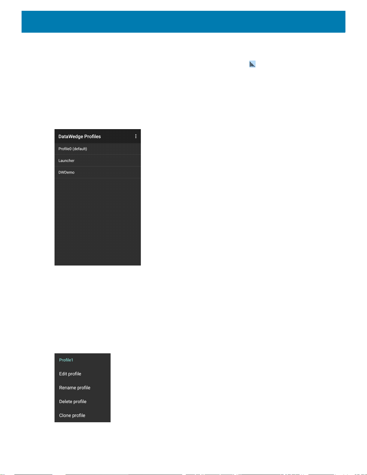
Profiles Screen
To launch DataWedge, swipe up from the bottom of the screen and touch . By default, three profiles appear:
•Profile0
• Launcher
•DWDemo.
Profile0 is the default profile and is used when no other profile can be applied.
Figure 44 DataWedge Profiles Screen
DataWedge
Profile names are color coded. Enabled profiles are white and disabled profiles are gray.
To configure a profile touch the profile name.
Profile Context Menu
Touch and hold a profile to open a context menu that allows additional actions to be performed on the selected
profile.
Figure 45 Profile Context Menu
The profile context menu allows the profile to be edited (same as just tapping on a profile), renamed or deleted.
64
Page 65
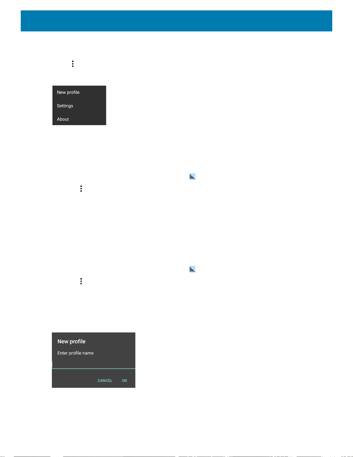
Options Menu
Touch to open the options menu.
Figure 46 DataWedge Options Menu
The menu provides options to create a new profile, access to general DataWedge settings and DataWedge
version information.
Disabling DataWedge
1. Swipe up from the bottom of the screen and touch .
DataWedge
2. Touch .
3. Touch Settings.
4. Touch DataWedge enabled.
The blue check disappears from the checkbox indicating that DataWedge is disabled.
Creating a New Profile
To create a new profile:
1. Swipe up from the bottom of the screen and touch .
2. Touch .
3. Touch New profile.
4. In the New profile dialog box, enter a name for the new profile. It is recommended that profile names be
unique and made up of only alpha-numeric characters (A-Z, a-z, 0-9).
Figure 47 New Profile Name Dialog Box
5. Touch OK.
The new profile name appears in the DataWedge profile screen.
65
Page 66
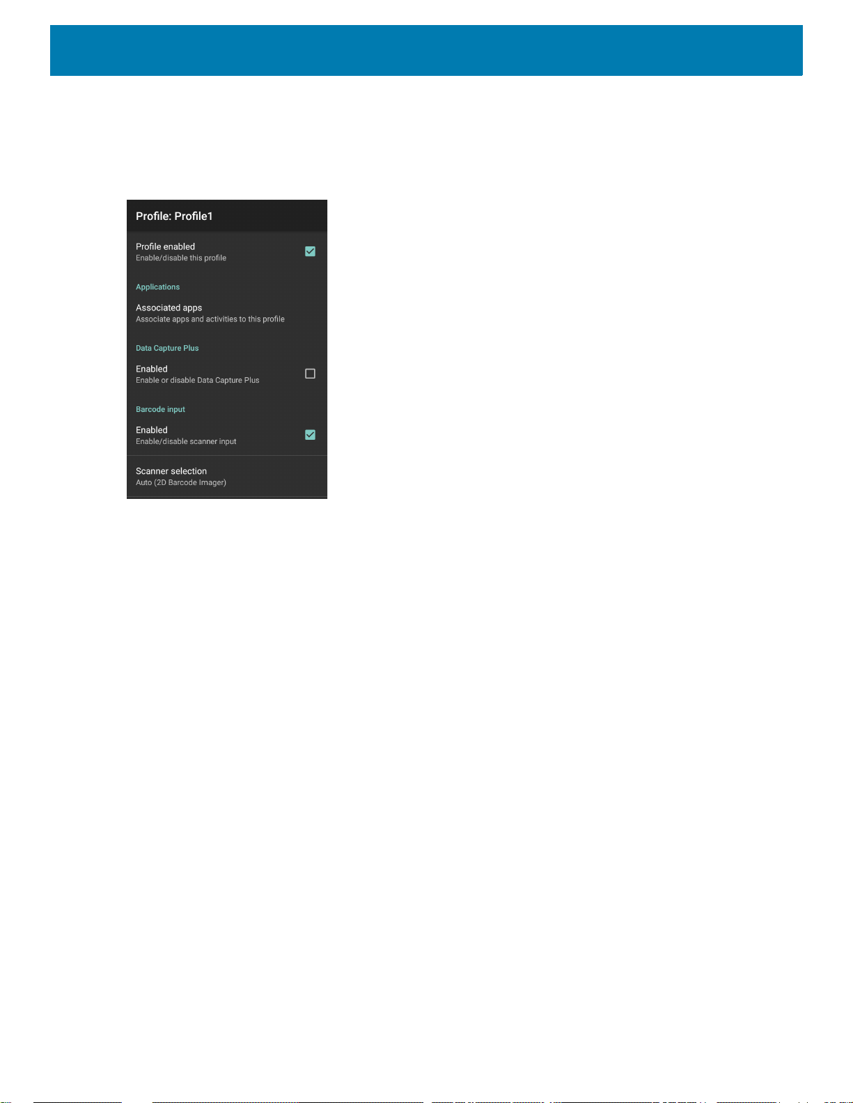
Profile Configuration
To configure the Profile0 or a user-created profile, touch the profile name.
Figure 48 Profile Configuration Screen
DataWedge
The configuration screen lists the following sections:
• Profile enabled
• Applications
• Data Capture Plus (DCP)
• Barcode Input
• Keystroke output
• Intent Output
• Voice Output
• IP Output.
Associating Applications
Use Applications option to associate applications with this profile. User created profiles should be associated
with one or more applications and its activities.
66
Page 67
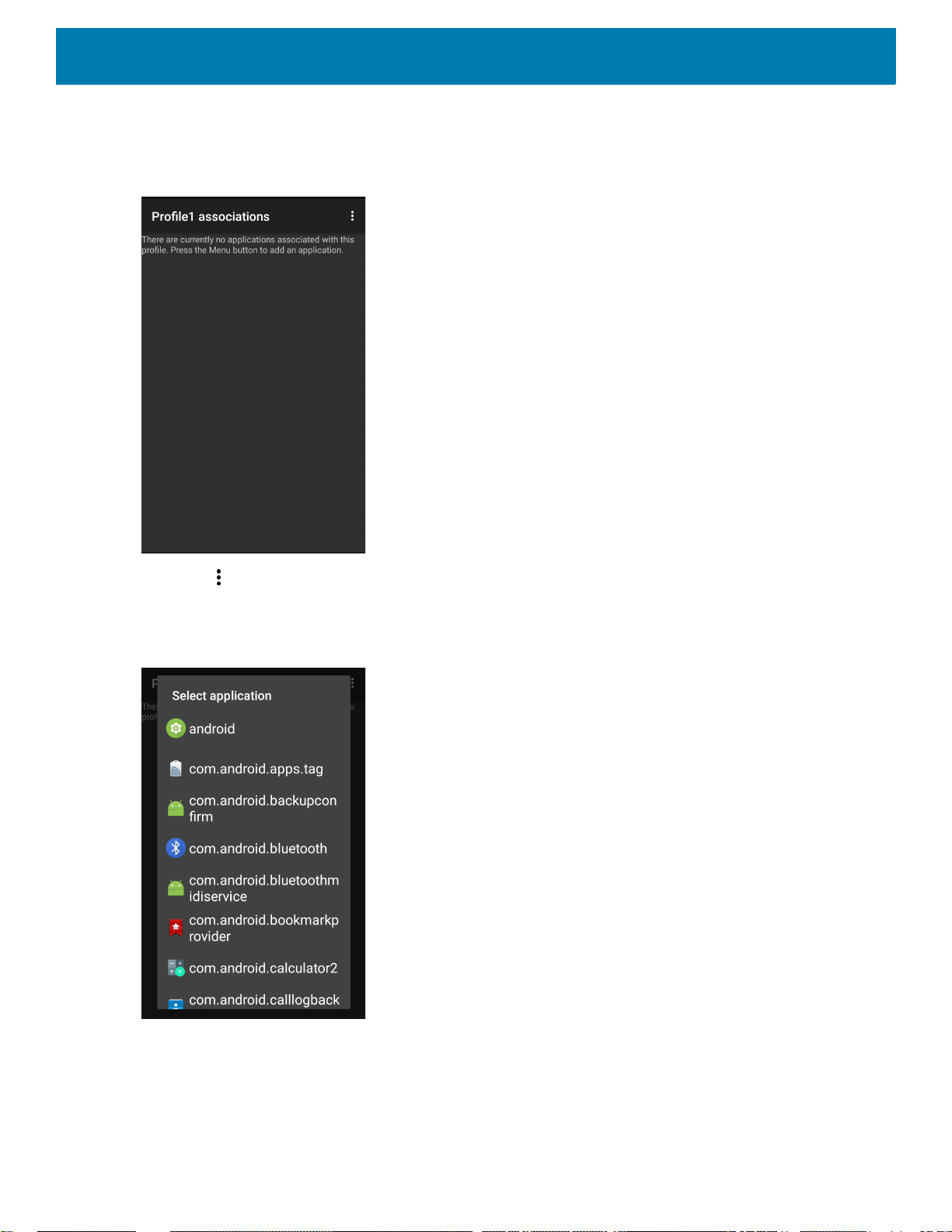
DataWedge
1. Touch Associated apps. A list of applications/activities associated with the profile displays. Initially the list
does not contain any applications/activities.
Figure 49 Associated Apps Screen
2. Touch .
3. Touch New app/activity.
Figure 50 Select Application Menu
4. In the Select application screen, select the desired application from the list.
5. In the Select activity menu, selecting the activity adds that application/activity combination to the
associated application list for that profile. Selecting * as the activity results in all activities within that
application being associated to the profile. During operation, DataWedge tries to match the specific
67
Page 68
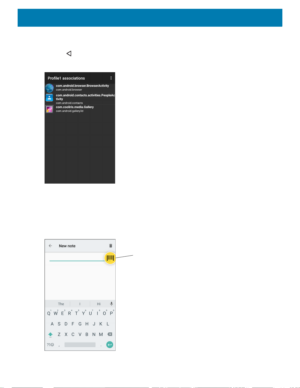
DataWedge
DCP Button
application/activity combinations with the foreground application/activity before trying to match the general
application/* combinations.
6. Touch .
Figure 51 Selected Application/Activity
Data Capture Plus
Data Capture Plus (DCP) is a DataWedge feature that enables the user to initiate data capture by touching a
designated part of the screen. A variable screen overlay acts like a scan button.
Figure 52 Minimized Data Capture Panel
68
Page 69
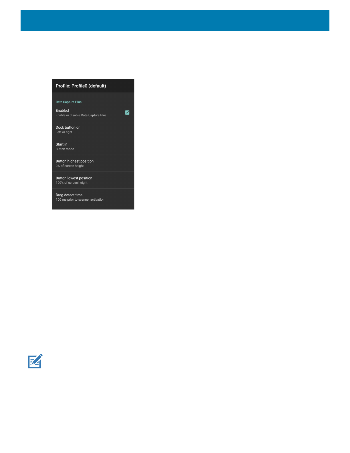
DataWedge
The DataWedge profile configuration screen allows the user to configure how the DCP appears on the screen
once the particular profile is enabled. The DCP is hidden by default. Enabling DCP option displays seven
additional configuration parameters.
Figure 53 Data Capture Panel Settings
• Enable - Select to enable Data Capture Plus (default - disabled).
• Dock button on - Select position of the button.
• Left or right - Allows user to place the button on either the right or left edge of the screen.
• Left only - Places the button on left edge of the screen.
• Right only - Places the button on the right edge of the screen.
• Start in - Select the initial DCP state.
• Fullscreen mode - DCP covers the whole screen.
• Button mode - DCP displays as a circular button on the screen and can be switched to fullscreen mode.
• Button only mode - DCP displays as a circular button on the screen and cannot be switched to
fullscreen mode.
• Button highest position - Select the top of the range the user is allowed to move the DCP, given as a
percent of the screen height (default - 0).
• Button lowest position - Select the bottom of the range the user is allowed to move the DCP, given as a
percent of the screen height (default - 100).
• Drag detect time - Select the time in milliseconds that the scanner waits before activating scanner. This
allows the user to drag the button without initiating scanner (default - 100 ms, maximum 1000 ms).
NOTE: The DCP does not appear if the scanner is disabled in the profile even though the Enabled option is set.
69
Page 70
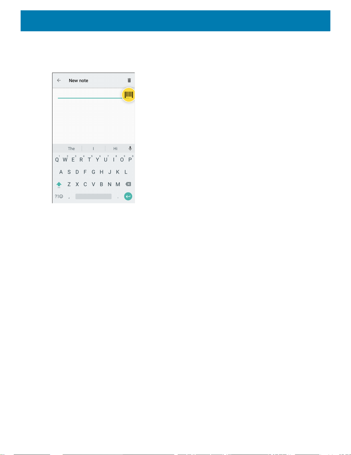
DataWedge
In Button mode, the user can place DCP in full screen mode by dragging the button over Fullscreen mode.
The overlay covers the screen.
Figure 54 Maximized DCP
Swipe down to return to button mode.
Barcode Input
Use the Barcode Input options to configure the Barcode Scanner Input Plug-in for the profile.
Enabled
Enables or disables this plug-in. A check in the checkbox indicates that the plug-in is enabled.
Scanner Selection
Configures which scanning device to use for barcode data capture when the profile is active.
• Auto - The software automatically determines the best scanning device.
• Camera Scanner - Scanning is performed with the rear-facing camera.
• 2D Barcode Imager - Scanning is performed using the 2D Imager.
• Bluetooth Scanner - Scanning is performed using the optional Bluetooth scanner.
• RS6000 Bluetooth Scanner - Scanning is performed using the RS6000 Bluetooth scanner.
• DS3678 Bluetooth Scanner - Scanning is performed using the DS3678 Bluetooth scanner.
• LI3678 Bluetooth Scanner - Scanning is performed using the DS3678 Bluetooth scanner.
Auto Switch to Default on Event
This feature configures DataWedge to select an external scanner as the default scanning device immediately
upon connection and revert to a built-in scanner when the external scanner is disconnected. External scanners
include those connecting by Bluetooth, serial cable or snap-on module. Disabled by default. This is only
available when Scanner Selection is set to Auto.
70
Page 71

DataWedge
This helps reduce scanning workflow interruptions when a Bluetooth scanner is introduced and/or it becomes
disconnected due to losing power or moving out of range.
For Bluetooth scanners, if the device was not previously paired, a pairing barcode displays prior to automatic
connection.
• Disabled - No scanner switching occurs when an external scanner is connected or disconnected (default).
• On connect - Selects the external scanner as the default scanning device immediately upon connection.
• On disconnect - Reverts to a built-in scanner based on its position in an internally managed scanner list
(which varies by host device). This is usually the scanner most recently used prior to the external
connection (see notes below).
• On connect/disconnect - Selects an external scanner as the default scanning device immediately upon
connection. Upon disconnection, reverts to the scanner set as the default prior to the external connection.
NOTE: The system selects the default scanner based on the connection state and the scanner's position in an internally
managed scanner list. If the newly connected scanner is lower in the scanner list than the one currently selected as the default scanner, the newly connected scanner becomes the default scanner.
On devices with only one built-in scanner or imager, On disconnect reverts to that built-in scanner or imager.
Configure Scanner Settings
Select Configure Scanner Settings to set the following:
• Select scanner to set parameters
• Decoders
• Decoder params
• UPC/EAN params
• Reader params
• Scan params
• UDI params
• Basic Multibarcode params
• Keep enabled on suspend
Decoders
Configures which barcode decoders are enabled or disabled. For best performance disable all unnecessary
decoders.
Touch Decoders. The Barcode input screen appears. A check in the checkbox indicates that the decoder is
enabled. By default the most commonly used decoders are enabled (shown below with an asterisk). The
supported decoders are:
NOTE: DataWedge supports the decoders listed below but not all are validated on this device.
71
Page 72

DataWedge
Table 5 Supported Decoders
Decoders
SE2100
Internal Imager
SE4710
Internal Imager
RS6000
RS507/RS507X
DS2278
DS3678
Australian PostalOOOOOO--
Aztec XXXXXX--
Canadian Postal O O -- O -- -- --
LI3678
Chinese 2 of 5 OOOOOOO
Codabar XXXXXXX
Code 11 OOOOOOO
Code 128 XXXXXXX
Code 39 XXXXXXX
Code 93 OOOOOOO
Composite AB OOOOOO--
Composite C OOOOOO--
Discrete 2 of 5 OOOOOOO
Datamatrix XXXXXX--
Dutch Postal OOOOOO--
EAN13 XXXXXXX
EAN8 XXXXXXX
GS1 DataBar XXXXXXX
GS1 DataBar
XXXXXXX
Expanded
GS1 DataBar
OOOOOOO
Limited
GS1 Datamatrix O O -- O O O --
GS1 QRCode OO--OOO--
HAN XIN O O -- O O O --
Key
X = Enabled
O = Disabled
-- = Not Supported
72
Page 73
DataWedge
Table 5 Supported Decoders (Continued)
Decoders
SE2100
Internal Imager
SE4710
Internal Imager
RS6000
RS507/RS507X
DS2278
DS3678
Interleaved 2 of 5OOOOOOO
Japanese PostalOOOOOO--
Korean 3 of 5 OOOOOOO
MAIL MARK XX--XXX--
Matrix 2 of 5 OOOOOOO
Maxicode XXXXXX--
LI3678
MicroPDF OOOOOO--
MicroQR OOOOOO--
MSI OOOOOOO
PDF417 XXXXXX--
QR Code XXXXXX--
Decoder
OOOOO-- --
Signature
TLC 39 OOOOOOO
Trioptic 39 OOOOOOO
UK Postal OOOOOO--
UPCA XXXXXXX
UPCE0 XXXXXXX
UPCE1 OOOOOOO
US4state OOOOOO--
US4state FICS OOOOOO--
US Planet OOOOOO--
US Postnet OOOOOO--
Key
X = Enabled
O = Disabled
-- = Not Supported
Touch to return to the previous screen.
73
Page 74

DataWedge
Decoder Params
Use Decode Params to configure individual decoder parameters.
NOTE: Not all parameter options are available with all scanners. See the DataWedge app on each device for the available
scanners and parameter options.
Codabar
• CLSI Editing - Enable this parameter to strip the start and stop characters and insert a space after the first,
fifth, and tenth characters of a 14-character Codabar symbol. Enable this feature if the host system requires
this data format (default - disabled).
• Length1 - Use to set decode lengths (default - 6). See Decode Lengths on page 79 for more information.
• Length2 - Use to set decode lengths (default - 55). See Decode Lengths on page 79 for more information.
• NOTIS Editing - Enable this parameter to strip the start and stop characters from a decoded Codabar
symbol. Enable this feature if the host system requires this data format (default - disabled).
• Redundancy - Sets the reader to read the barcode twice before accepting data. A check in the checkbox
indicates that redundancy is enabled (default - enabled).
Code 11
• Length1 - Use to set decode lengths (default - 4). See Decode Lengths on page 79 for more information.
• Length2 - Use to set decode lengths (default - 55). See Decode Lengths on page 79 for more information.
• Redundancy - Sets the reader to read the barcode twice before accepting data. A check in the checkbox
indicates that redundancy is enabled (default - enabled).
• Report Check Digit - Transmit Code 11 data with or without the check digit. A check in the checkbox
indicates to send Code 11 data with check digit (default - disabled).
• Verify Check Digit - Check the integrity of all Code 11 symbols to verify that the data complies with the
specified check digit algorithm. This selects the check digit mechanism for the decoded Code 11 barcode.
• No Check Digit - Do not verify check digit.
• 1 Check Digit - Barcode contains one check digit (default).
• 2 Check Digits - Barcode contains two check digits.
Code128
• Code128 Reduced Quiet Zone - Enables decoding of margin-less Code 128 barcodes (default - disabled).
• Ignore Code128 FCN4 - When enabled, and a Code 128 barcode has an embedded FNC4 character, it will
be removed from the data and the following characters will not be changed. When the feature is disabled,
the FNC4 character will not be transmitted but the following character will have 128 added to it (default disabled).
• Check ISBT Table - The ISBT specification includes a table that lists several types of ISBT barcodes that
are commonly used in pairs. If ISBT128 Concat Mode is set, enable Check ISBT Table to concatenate only
those pairs found in this table. Other types of ISBT codes are not concatenated. A check in the checkbox
indicates that redundancy is enabled (default - disabled).
• Enable GS1-128 - Set the GS1 128 subtype. A check in the checkbox indicates that the option is enabled
(default - enabled).
• Enable ISBT128 - Set the ISBT128 subtype. A check in the checkbox indicates that the option is enabled
(default - enabled).
74
Page 75

DataWedge
• Enable Plain Code128 - Set the Plain Code128 subtype. Enables other (non-EAN or ISBT) Code 128
subtypes. A check in the checkbox indicates that the option is enabled (default - enabled).
• ISBT128 Concatenation Mode - Select an option for concatenating pairs of ISBT code types:
• Concat Mode Never - Do not concatenate pairs of ISBT codes encountered (default).
• Concat Mode Always - There must be two ISBT codes in order to decode and perform concatenation.
Does not decode single ISBT symbols.
• Concat Mode Auto - Decodes and concatenates pairs of ISBT codes immediately. If only a single ISBT
symbol is present, the device must decode the symbol the number of times set via DataWedge
Configuration 4 - 11 Redundancy - Code128 before transmitting its data to confirm that there is no
additional ISBT symbol.
• Length1 - Use to set decode lengths (default - 0). See Decode Lengths on page 79 for more information.
• Length2 - Use to set decode lengths (default - 55). See Decode Lengths on page 79 for more information.
• Redundancy - Sets the reader to read the barcode twice before accepting data. A check in the checkbox
indicates that redundancy is enabled (default - disabled).
• Security Level - The scanner offers four levels of decode security for Code 128 barcodes. Select
increasing levels of security for decreasing levels of barcode quality. There is an inverse relationship
between security and scanner aggressiveness, so choose only that level of security necessary for any
given application.
• Security Level 0 - This setting allows the scanner to operate in its most aggressive state, while
providing sufficient security in decoding most “in-spec” barcodes.
• Security Level 1 - This setting eliminates most misdecodes (default).
• Security Level 2 - Select this option if Security level 1 fails to eliminate misdecodes.
• Security Level 3 - If Security Level 2 is selected and misdecodes still occur, select this security level.
Be advised, selecting this option is an extreme measure against mis-decoding severely out of spec
barcodes. Selecting this level of security significantly impairs the decoding ability of the scanner. If this
level of security is needed, try to improve the quality of the barcodes.
Code39
•
Code39 Reduced Quiet Zone - Enables decoding of margin-less Code 39 barcodes (default - disabled).
• Convert Code39 To Code32 - Code 32 is a variant of Code 39 used by the Italian pharmaceutical industry.
Scan the appropriate barcode below to enable or disable converting Code 39 to Code 32 (default disabled).
• Full ASCII- Code 39 Full ASCII is a variant of Code 39 that pairs characters to encode the full ASCII
character set. To enable or disable Code 39 Full ASCII (default - disabled),
• Length1 - Use to set decode lengths (default - 0). See Decode Lengths on page 79 for more information.
• Length2 - Use to set decode lengths 4 (default - 55). See Decode Lengths on page 79 for more
information.
• Redundancy - Sets the reader to read the barcode twice before accepting data. A check in the checkbox
indicates that redundancy is enabled (default - disabled).
• Report Check Digit - Transmit Code 39 data with or without the check digit. A check in the checkbox
indicates to send Code 39 data with check digit (default - disabled).
• Report Code32 Prefix - Scan the appropriate barcode to enable or disable adding the prefix character “A”
to all Code 32 barcodes (default - disabled).
75
Page 76

DataWedge
• Security Level - Options: Security level 0, Security Level 1, Security Level 2 and Security Level 3
(default - Security level 1).
• Security Level 0 - This setting allows the scanner to operate in its most aggressive state, while
providing sufficient security in decoding most “in-spec” barcodes.
• Security Level 1 - This setting eliminates most misdecodes (default).
• Security Level 2 - Select this option if Security level 1 fails to eliminate misdecodes.
• Security Level 3 - If Security Level 2 is selected and misdecodes still occur, select this security level.
Be advised, selecting this option is an extreme measure against mis-decoding severely out of spec
barcodes. Selecting this level of security significantly impairs the decoding ability of the scanner. If this
level of security is needed, try to improve the quality of the barcodes.
• Verify Check Digit - Enable this feature to check the integrity of all Code 39 symbols to verify that the data
complies with a specified check digit algorithm. The digital scanner decodes only those Code 39 symbols
that include a modulo 43 check digit. Enable this feature only if the Code 39 symbols contain a modulo 43
check digit (default - disabled).
Code93
• Length1 - Use to set decode lengths (default - 0). See Decode Lengths on page 79 for more information.
• Length2 - Use to set decode lengths (default - 55). See Decode Lengths on page 79 for more information.
• Redundancy - Sets the reader to read the barcode twice before accepting data. A check in the checkbox
indicates that redundancy is enabled (default - disabled).
Composite AB
• UCC Link Mode
• Link Flag ignored - 1D component is transmitted regardless of whether a 2D component is detected.
• Always Linked - 1D and the 2D components are transmitted. If 2D is not present, the 1D component is
not transmitted.
• Auto Discriminate - the digital scanner determines if there is a 2D portion, then transmits the 1D
component, as well as the 2D portion if present. (default).
Discrete 2 of 5
• Length1 - Use to set decode lengths (default - 0). See Decode Lengths on page 79
• Length2 - Use to set decode lengths (default - 14). See Decode Lengths on page 79 for more information.
• Redundancy - Sets the reader to read the barcode twice before accepting data. A check in the checkbox
indicates that redundancy is enabled (default - enabled).
GS1 DataBar Limited
• GS1 Limited Security Level
• GS1 Security Level 1 - This setting allows the scanner to operate in its most aggressive state, while
providing sufficient security in decoding most “in-spec” barcodes.
• GS1 Security Level 2 - This setting eliminates most misdecodes (default).
• GS1 Security Level 3 - Select this option if Security level 2 fails to eliminate misdecodes.
• GS1 Security Level 4 - If Security Level 3 is selected and misdecodes still occur, select this security
level. Be advised, selecting this option is an extreme measure against mis-decoding severely out of
spec barcodes. Selecting this level of security significantly impairs the decoding ability of the scanner. If
this level of security is needed, try to improve the quality of the barcodes.
for more information.
76
Page 77

DataWedge
HAN XIN
• HAN XIN Inverse
• Disable - Disables decoding of HAN XIN inverse barcodes (default).
• Enable - Enables decoding of HAN XIN inverse barcodes.
• Auto - Decodes both HAN XIN regular and inverse barcodes.
Interleaved 2 of 5
• Check Digit
• No Check Digit - A check digit is not used. (default)
• USS Check Digit - Select to check the integrity of all Interleaved 2 of 5 symbols to verify the data
complies with either the Uniform Symbology Specification (USS) check digit algorithm.
• OPCC Check Digit - Select to check the integrity of all Interleaved 2 of 5 symbols to verify the data
complies with either the Optical Product Code Council (OPCC) check digit algorithm.
• Length1 - Use to set decode lengths (default - 14). See Decode Lengths on page 79 for more information.
• Length2 - Use to set decode lengths (default - 10). See Decode Lengths on page 79 for more information.
• Redundancy - Sets the reader to read the barcode twice before accepting data. A check in the checkbox
indicates that redundancy is enabled (default - enabled).
• Report Check Digit - Transmit Interleaved 2 of 5 data with or without the check digit. A check in the
checkbox indicates to send Interleaved 2 of 5 data with check digit (default - disabled).
• I2of5 Security Level - Options: I2of5 Security level 0, I2of5 Security Level 1, I2of5 Security Level 2
and I2of5 Security Level 3 (default - I2of5 Security level 1).
• Convert ITF-14 To EAN13 - Convert 14-character Interleaved 2 of 5 barcodes to EAN-13, and transmit as
EAN-13. The Interleaved 2 of 5 barcode must be enabled and must have a leading zero and a valid EAN-13
check digit. A check in the checkbox indicates that the option is enabled (default - disabled).
• I2of5 Reduced Quiet Zone - Enables decoding of margin-less I2of5 barcodes (default - disabled).
Matrix 2 of 5
• Length1 - Use to set decode lengths (default - 10). See Decode Lengths on page 79 for more information.
• Length2 - Use to set decode lengths (default - 0). See Decode Lengths on page 79 for more information.
• Redundancy - Sets the reader to read the barcode twice before accepting data. A check in the checkbox
indicates that redundancy is enabled (default - disabled).
• Report Check Digit - Transmit Matrix 2 of 5 data with or without the check digit. A check in the checkbox
indicates to send Matrix 2 of 5 data with check digit (default - enabled).
• Verify Check Digit - Enable this feature to check the integrity of all Matrix 2 of 5 symbols to verify that the
data complies with a specified check digit algorithm (default - enabled).
MSI
• Check Digit - With MSI symbols, one check digit is mandatory and always verified by the reader. The
second check digit is optional.
• One Check Digit - Verify one check digit (default).
• Two Check Digits - Verify two check digits.
• Check Digit Scheme - Two algorithms are possible for the verification of the second MSI check digit.
Select the algorithm used to encode the check digit.
• Mod-11-10 - First check digit is MOD 11 and second check digit is MOD 10 (default).
• Mod-10-10 - Both check digits are MOD 10.
• Length 1 - Use to set decode lengths (default - 4). See Decode Lengths on page 79 for more information.
77
Page 78

DataWedge
• Length 2 - Use to set decode lengths (default - 55). See Decode Lengths on page 79 for more information.
• Redundancy - Sets the reader to read the barcode twice before accepting data. A check in the checkbox
indicates that redundancy is enabled (default - enabled).
• Report Check Digit - Transmit MSI data with or without the check digit. A check in the checkbox indicates
to send MSI data with check digit (default - disabled).
Trioptic 39
• Redundancy - Sets the reader to read the barcode twice before accepting data. A check in the checkbox
indicates that redundancy is enabled (default - disabled).
UK Postal
• Report Check Digit - Transmit UK Postal data with or without the check digit. A check in the checkbox
indicates to send UK Postal data with check digit (default - disabled).
UPCA
• Preamble - Preamble characters are part of the UPC symbol consisting of Country Code and System
Character. Select the appropriate option to match the host system.
There are three options for transmitting a UPCA preamble:
• Preamble None - Transmit no preamble.
• Preamble Sys Char - Transmit System Character only (default).
• Preamble Country and Sys Char - Transmit System Character and Country Code (“0” for USA). Select
the appropriate option to match the host system.
• Report Check Digit - The check digit is the last character of the symbol used to verify the integrity of the
data. Enables or disables this option. A check in the checkbox indicates that the option is enabled (default enabled).
UPCE0
• Convert UPCE0 To UPCA - Enable to convert UPCE0 (zero suppressed) decoded data to UPC-A format
before transmission. After conversion, the data follows UPC-A format and is affected by UPC-A
programming selections. Disable to transmit UPCE0 decoded data as UPCE0 data, without conversion
(default - disabled).
• Preamble - Preamble characters are part of the UPC symbol consisting of Country Code and System
Character. Select the appropriate option to match the host system.
There are three options for transmitting a UPCE0 preamble:
• Preamble None - Transmit no preamble (default).
• Preamble Sys Char - Transmit System Character only.
• Preamble Country and Sys Char - Transmit System Character and Country Code (“0” for USA).
• Report Check Digit - The check digit is the last character of the symbol used to
data. Enables or disables this option. A check in the checkbox indicates that the option is enabled (default disabled).
UPCE1
• Convert UPCE1 To UPCA - Enable this to convert UPCE1 decoded data to UPC-A format before
transmission. After conversion, the data follows UPC-A format and is affected by UPC-A programming
selections. Disable this to transmit UPCE1 decoded data as UPCE1 data, without conversion (default disabled).
verify the integrity of the
78
Page 79

DataWedge
• Preamble - Preamble characters are part of the UPC symbol consisting of Country Code and System
Character. Select the appropriate option to match the host system.
There are three options for transmitting a UPCE1 preamble:
• Preamble None - Transmit no preamble (default).
• Preamble Sys Char - Transmit System Character only.
• Preamble Country and Sys Char - Transmit System Character and Country Code (“0” for USA).
• Report Check Digit - The check digit is the last character of the symbol used to verify the integrity of the
data. Enables or disables this option. A check in the checkbox indicates that the option is enabled (default disabled).
US Planet
• Report Check Digit - The check digit is the last character of the symbol used to verify the integrity of the
data. Enables or disables this option. A check in the checkbox indicates that the option is enabled (default disabled).
Decode Lengths
The allowable decode lengths are specified by options Length1 and Length2 as follows:
• Variable length: Decode symbols containing any number of characters.
• Set both Length1 and Length2 to 0.
• Range: Decode a symbol with a specific length range (from
•Set Length1 to
• Two Discrete Lengths: Decode only symbols containing either of two selected lengths.
• Set both Length1 or Length2 to the specific lengths. Length1 must be greater than Length2.
• One Discrete Length: Decode only symbols containing a specific length.
• Set both Length1 and Length2 to the specific length.
a
and set Length2 to b.
a
to b, including a and b).
UPC EAN Params
Allows the configuration of the parameters that apply to more than one UPC or EAN decoder.
NOTE: Not all parameter options are available with all scanners. See the DataWedge app on each device for the available
scanners and parameter options.
• Convert DataBar To UPC EAN - If this is set it converts DataBar barcodes to UPC/EAN format. For this
setting to work UPC/EAN symbologies must be enabled. A check in the checkbox indicates that the option
is enabled. (default - disabled).
• UPC Reduced Quiet Zone - Enables decoding of margin-less UPC barcodes. (default - disabled)
• Bookland - Enable Bookland decoding. A check in the checkbox indicates that the option is enabled.
(default - disabled).
• Bookland Format - If Bookland EAN is enabled, select one of the following formats for Bookland data:
• Format ISBN-10 - The decoder reports Bookland data starting with 978 in traditional 10-digit format with
the special Bookland check digit for backward-compatibility. Data starting with 979 is not considered
Bookland in this mode. (default)
• Format ISBN-13 - The decoder reports Bookland data (starting with either 978 or 979) as EAN-13 in
13-digit format to meet the 2007 ISBN-13 protocol.
• Coupon - Enables Coupon code decoding. Note that in order to successfully decode Coupon codes, all of
the correct decoders must be enabled. A check in the checkbox indicates that the option is enabled.
(default - disabled).
79
Page 80

DataWedge
• Coupon Report Mode - Traditional coupon symbols are composed of two barcode: UPC/EAN and Code
128. A new coupon symbol is composed of a single Data Expanded barcode. The new format offers more
options for purchase values (up to $999.999) and supports complex discount offers as a second purchase
requirement. An interim coupon symbol also exists that contain both types of barcodes: UPC/EAN and
Databar Expanded. This format accommodates both retailers that do not recognize or use the additional
information included in the new coupon symbol, as well as those who can process new coupon symbols.
• Old Coupon Report Mode - Scanning an old coupon symbol reports both UPC and Code 128,
scanning is interim coupon symbol reports UPC, and scanning a new coupon symbol reports nothing
(no decode).
• New Coupon Report Mode - Scanning an old coupon symbol reports either UPC or Code 128, and
scanning an interim coupon symbol or a new coupon symbol reports Databar Expanded.
• Both Coupon Report Modes - Scanning an old coupon symbol reports both UPC and Code 128, and
scanning an interim coupon symbol or a new coupon symbol reports Databar Expanded. (default)
• Ean Zero Extend – Enable this parameter to add five leading zeros to decoded EAN-8 symbols to make
them compatible in format to EAN-13 symbols. Disable this to transmit EAN-8 symbols as is. Default –
disabled.
• Linear Decode - This option applies to code types containing two adjacent blocks (e.g., UPC-A, EAN-8,
EAN-13). Enable this parameter to transmit a barcode only when both the left and right blocks are
successfully decoded within one laser scan. Enable this option when barcodes are in proximity to each
other (default - enabled).
• Retry Count - Retry count for auto-discriminating for supplementals. Possible values are 2 to 20 inclusive.
Note that this flag is only considered if Supplemental Mode - UPC EAN is set to one of the following values:
Supplementals Auto, Supplementals Smart, Supplementals 378-379, Supplementals 978-979,
Supplementals 977 or Supplementals 414-419-434-439 (2 to 20, default 10).
• Security Level - The scanner offers four levels of decode security for UPC/EAN barcodes. Select higher
security levels for lower quality barcodes. There is an inverse relationship between security and decode
speed, so be sure to choose only that level of security necessary for the application.
• Level 0 - This default setting allows the scanner to operate fastest,
decoding “in-spec” UPC/EAN barcodes.
• Level 1 - As barcode quality levels diminish, certain characters become prone to misdecodes before
others (i.e., 1, 2, 7, 8). If the scanner is misdecoding poorly printed barcodes, and the misdecodes are
limited to these characters, select this security level. (default).
• Level 2 - If the scanner is misdecoding poorly printed barcodes, and the misdecodes are not limited to
characters 1, 2, 7, and 8, select this security level.
• Level 3 - If the scanner is still misdecoding, select this security level. Be advised, selecting this option is
an extreme measure against misdecoding severely out of spec barcodes. Selecting this level of security
can significantly impair the decoding ability of the scanner. If this level of security is necessary, try to
improve the quality of the barcodes.
• Supplemental2 - Enables or disables this option. A check in the checkbox indicates that the option is
enabled.
• Supplemental5 - Enables or disables this option. A check in the checkbox indicates that the option is
enabled.
• Supplemental Mode
• No Supplementals - the scanner is presented with a UPC/EAN plus supplemental symbol, the scanner
decodes UPC/EAN and ignores the supplemental characters (default).
• Supplemental Always - the scanner only decodes UPC/EAN symbols with supplemental characters,
and ignores symbols without supplementals.
• Supplements Auto - the scanner decodes UPC/EAN symbols with supplemental characters
immediately. If the symbol does not have a supplemental, the scanner must decode the barcode the
while providing sufficient security in
80
Page 81

DataWedge
number of times set via UPC/EAN Supplemental Redundancy before transmitting its data to confirm that
there is no supplemental.
• Supplemental Smart - Enables smart supplementals. In this mode the decoder returns the decoded
value of the main block right away if it does not belong to one of the following supplemental types: 378,
379, 977, 978, 979, 414, 419, 434 or 439. If the barcode starts with one of the prefixes it searches the
image more aggressively for a supplemental. Tries to scan the supplemental if it is present. If the
supplemental scanning failed, then the main barcode is returned.
• Supplemental 378-379 - Enables (auto-discriminate) supplemental for UPC/EAN codes starting with
378 or 379. Disables reading of supplementals for any other UPC/EAN barcode not starting with 378 or
379. Tries to scan the supplemental if it is present. If the supplemental scanning failed, then the main
barcode is returned.
• Supplemental 978-979 - Enables (auto-discriminate) supplemental for UPC/EAN codes starting with
978 or 979. Disables reading of supplementals for another UPC/EAN barcode not starting with 978 or
979. Tries to scan the supplemental if it is present. If the supplemental scanning failed, then the main
barcode is returned.
• Supplemental 414-419-434-439 - Enables (auto-discriminate) supplemental for UPC/EAN codes
starting with 414, 419, 434 or 439. Disables reading of supplementals for another UPC/EAN barcode 4 16 not starting with 414, 419, 434 or 439. Tries to scan the supplemental if it is present. If the
supplemental scanning failed, then the main barcode is returned.
• Supplemental 977 - Enables (auto-discriminate) supplemental for UPC/EAN codes starting with 977.
Disables reading of supplementals for another UPC/EAN barcode not starting with 977. Tries to scan
the supplemental if it is present. If the supplemental scanning failed, then the main barcode is returned.
Reader Params
Allows the configuration of parameters specific to the selected barcode reader.
NOTE: Not all parameter options are available with all scanners. See the DataWedge app on each device for the available
scanners and parameter options.
• Character Set Configuration - Used to support the GB2312 Chinese characters encoding.
• Character Set Selection - Allows the user to convert the barcode data if different from default encoding
type.
• Auto Character Set Selection (Best Effort) - Automatic character convert option. Tries to decode
data from the Preferred selection. The first correct decodable character set is used to convert the
data and is sent.
• ISO-8859-1 - Part of the ISO/IEC 8859 series of ASCII-based standard character encodings. It is
generally intended for Western European languages.
• Shift_JIS - Shift Japanese Industrial Standards (JIS) is a character encoding for the Japanese
language.
• GB18030 - Chinese coded character set that defines the required language and character support
necessary for software in China.
• UTF-8 - A character encoding capable of encoding all possible characters, or code points, defined by
Unicode (default).
• Auto Character Set Preferred Order - In Auto Character Set Selection mode, the system will try to
decode the data in a preference order of character sets. The algorithm used is a best effort one. That is,
there could be cases where the data can be decoded from more than one character set. The first
character set from the preferred list which can decode the data successfully will be chosen to decode
the data and sent to the user. Any other character set that is in the list but lower in the preferred order,
would not be considered, even if the data could be successfully decoded using such character set.
The preferred character set and its preference order is configurable to the user through the Auto
Character Set Preferred Order menu. Users can change the order by dragging the icon for that menu
81
Page 82

DataWedge
item. To delete an item, long press on an item and the Delete option will appear. To add a new item, tap
the menu icon at top right corner and options to add UTF-8 and GB2312 will appear.
•UTF-8 - A character encoding capable of encoding all possible characters, or code points, defined by
Unicode (default).
• GB2312 - Character set of the People's Republic of China, used for simplified Chinese characters.
• Auto Character Set Failure Option - If the system cannot find a character set from the preferred list
that can be used to successfully decode the data, the character set selected in Auto Character Set
Failure Option is used to decode the data and send to the user. If NONE is used, Null data is returned
as string data.
•NONE
•UTF-8 - A character encoding capable of encoding all possible characters, or code points, defined by
Unicode (default).
• ISO-8859-1 - Part of the ISO/IEC 8859 series of ASCII-based standard character encodings. It is
generally intended for Western European languages.
• Shift_JIS - ended for Western European languages.
•Shift_JIS - Shift Japanese Industrial Standards (JIS) is a character encoding for the Japanese
language.
• GB18030 - Chinese coded character set that defines the required language and character support
necessary for software in China.
• Presentation Parameters - select Barcode Input for Scene Detection Qualifier.
• Proximity Sensor Input - enables Presentation mode only after a proximity event.
• None - enables Default Presentation Mode.
• 1D Quiet Zone Level - Sets the level of aggressiveness in decoding barcodes with a reduced quiet zone
(the area in front of and at the end of a barcode), and applies to symbologies enabled by a Reduced Quiet
Zone parameter. Because higher levels increase the decoding time and risk of misdecodes, Zebra strongly
recommends enabling only the symbologies which require higher quiet zone levels, and leaving Reduced
Quiet Zone disabled for all other symbologies.
Options are:
• 0 - The scanner performs normally in terms of quiet zone.
• 1 - The scanner performs more aggressively in terms of quiet zone (default).
• 2 - The scanner only requires one side EB (end of barcode) for decoding.
• 3 - The scanner decodes anything in terms of quiet zone or end of barcode.
• Adaptive Scanning - Not applicable.
• Disable
• Enable (default).
• Beam Width - Beam Width is applicable only with linear scanners.
•Narrow
• Normal (default)
•Wide
• Aim mode - Turns the scanner illumination on or off.
• On - Illumination on (default).
• Off - Illumination is off.
• Aim Timer - Sets the maximum amount of time that aiming remains on (0 - 60,000 ms in increments of 100
ms). A value of 0 sets the aim to stay on indefinitely (default - 500).
82
Page 83

DataWedge
• Aim Type - Set the aiming usage by selecting trigger, presentation or continuous read.
• Trigger - A trigger event activates decode processing, which continues until the trigger event ends or a
valid decode occurs (default).
• Presentation - Enables presentation mode scanning.
• Continuous Read- Select the soft trigger to start a continuous read of the same bar code. When the
imager detects an object in its field of view, it triggers and attempt to decode.
• Beam Timer - Sets the maximum amount of time that the reader remains on (0 - 60,000 ms in increments
of 100 ms). A value of 0 sets the reader to stay on indefinitely (default -5000).
• Time Delay to Low Power - Sets the time the decoder remains active after decoding. After a scan session,
the decoder waits this amount of time before entering Low Power Mode. Options: 1 Second (default), 30
Seconds, 1 Minute or 5 Minutes.
• Different Symbol Timeout - Controls the time the scanner is inactive between decoding different symbols.
Programmable in 500 msec increments from 0 to 5 seconds. The default is 500 msec.
• Digimarc Decoding - Enables/disables support for Digimarc, which encodes and invisibly integrates
traditional barcode data onto product packaging. Supported with internal imager only. (default - Enabled).
• Illumination Brightness - Sets the brightness of the illumination by altering LED power. The default is 10,
which is maximum LED brightness. For values from 1 to 10, LED brightness varies from lowest to highest
level of brightness.
• Illumination mode - Turns imager illumination on and off. This option is only available when Bluetooth
Scanner is selected in the Barcode input, Scanner selection option.
• Off - Illumination is off.
• On - Illumination is on (default).
• Inverse 1D Mode - This parameter allows the user to select decoding on inverse 1D barcodes.
• Disable - Disables decoding of inverse 1D barcodes (default).
• Enable - Enables decoding of only inverse 1D barcodes.
• Auto - Allows decoding of both twice positive and inverse 1D barcodes.
• Keep Pairing Info After Reboot
• Disable - Disables the ability to keep pairing info after reboot.
• Enable - Enables the ability to keep pairing info after reboot. (default).
• LCD Mode - Enables or disables LCD mode. LCD mode enhances the ability of the imager to read
barcodes from LCD displays such as cellphones.
• Disable - Disables the LCD mode (default).
• Enable - Enables LCD mode.
• Linear Security Level - Sets the number of times a barcode is read to confirm an accurate decode.
• Security Short or Codabar - Two times read redundancy if short barcode or Codabar (default).
• Security All Twice - Two times read redundancy for all barcodes.
• Security Long and Short - Two times read redundancy for long barcodes, three times for short
barcodes.
• Security All Thrice - Three times read redundancy for all barcodes.
• HW Engine Low Power Timeout - Time (0 - 1,000 ms in increments of 50 ms) of inactivity before scanner
enters low-power mode from (default - 250).
83
Page 84

DataWedge
• Picklist - Allows the imager to decode only the barcode that is directly within the illuminated scan dot. This
feature is useful in applications where multiple barcodes may appear in the field of view during a decode
session and only one of them is targeted for decode.
• Disabled – Disables Picklist mode. Any barcode within the field of view can be decoded (default).
• Enabled – Enables Picklist mode so that only the barcode under the projected reticle can be decoded.
• Poor Quality Decode Effort - Enable poor quality barcode decoding enhancement feature.
• Same Symbol Timeout - Controls the time the scanner is inactive between decoding same symbols.
Programmable in 500 msec increments from 0 to 5 seconds. The default is 500 msec.
• Scanning Modes - Scanning options available on the device.
• Single - Set to scan general barcodes (default).
• UDI - Set to scan healthcare specific barcodes.
Scan Params
Allows the configuration of Code ID and decode feedback options.
NOTE: Not all parameter options are available with all scanners. See the DataWedge app on each device for the available
scanners and parameter options.
• Code ID Type - A Code ID character identifies the code type of a scanned barcode. This is useful when the
reader is decoding more than one code type. Select a code ID character to insert between the prefix and
the decoded symbol.
• Code ID Type None - No prefix (default)
• Code ID Type AIM - Insert AIM Character prefix.
• Code ID Type Symbol - Insert Symbol character prefix.
• Engine Decode LED - Use to turn on scanner red LED when the scan beam is emitting either by scanner
trigger or using soft scan button.
• BT Disconnect On Exit - Bluetooth connection is disconnected when data capture application is closed .
• Connection Idle Time - Set connection idle time. The Bluetooth connection disconnects after being idle for
set time.
• Display BT Address Barcode - Enable or disable displaying Bluetooth Address barcode if there is no
Bluetooth scanner being paired when application tries to enable the Bluetooth scanner.
• Establish Connection Time - The timeout which the device will try to enable or reconnect to the Bluetooth
scanner when the Bluetooth scanner is not in the vicinity or not paired.
• Audio Feedback Mode - Select good decode audio indication.
• Local Audio Feedback - Good decode audio indication on device only.
• Remote Audio Feedback - Good decode audio indication.
• Both - Good decode audio indication on device and scanner (default).
• Disable - No good decode audio indication on either device or scanner.
• LED Feedback Mode - Select good decode LED indication.
• Local LED Feedback - Good decode LED indication on device only.
• Remote LED Feedback - Good decode LED indication on scanner.
• Both - Good decode LED indication on device and scanner (default).
• Disable - No good decode LED indication on either device or scanner.
• Decode Audio Feedback - Select an audio tone to sound upon a good decode (default optimized-beep).
• Decoding LED Notification - Enable the device to light the red Data Capture LED when data capture is in
progress. (default - disabled).
84
Page 85

DataWedge
• Decode Feedback LED Timer - Set the amount of time (in milliseconds) that the green Data Capture LED
stays lit after a good decode. (default - 75 msec.)
• Beep Volume Control - Set the good decode beep to a system or other sound. This allows for independent
control of the good beep volume.
NOTE: Not all ringtones are fully supported as decode tones and those of longer length may be truncated when used as a
decode tone. The recommendation is to test the selected tone for operation before deployment to a customer site.
• Ringer - Set the good decode beep to the ringer sound.
• Music and Media - Set the good decode beep to the media sound.
• Alarms - Set the good decode beep to the alarm sound.
• Notifications - Set the good decode beep to the notification sound (default).
UDI Params
Allows the configuration of parameters specific to healthcare barcodes.
• Enable UDI-GSI - Enable UDI using GS1 standards (default - enabled).
• Enable UDI-HIBCC - Enable UDI using HIBCC standards (default - enabled).
• Enable UDI-ICCBBA - Enable UDI using ICCBBA standards (default - enabled).
Keep enabled on suspend
Keep Bluetooth scanner enabled after suspend (default-disabled).
Voice Input
DataWedge supports Keystroke Output, which collects the processed data and sends it to the foreground
application as a series of keystrokes which helps data capturing to applications without writing any code.
DataWedge sends captured data via intents, where user applications can consume them in their applications
without worrying about the complexities to write code to capture the data. DataWedge is currently not capturing
data for Voice Input. Zebra GMS devices have a built in Google speech recognition engine. By making use of
the speech engine capabilities, DataWedge has extended automated data capturing to user applications
through voice.
Voice data capturing starts after you speak the predefined start phrase and it stops after you speak the data or
speak the end phrase, if one was defined.
IMPORTANT:
• Simultaneous use of Voice Input in DataWedge and Google Voice is not supported.
• Voice Input is not supported if the Enterprise Home Screen (EHS) is in restricted mode. However, enabling all of the
privilege settings in EHS reinstates Voice Input.
• Voice Input is not supported if the device language is changed to another language, for example Chinese.
Use Voice Input to configure the Voice Input Plug-in.
• Enabled - Enables or disables this plug-in. A check in the checkbox indicates that the plug-in is enabled.
• Data capture start phrase - Starts data capture with the phrase entered in this field.This field is
mandatory. (Default - start).
Providing numbers and other special characters as the data capture start phrase is not supported.
• Data capture end phrase - Ends data capture with the phrase entered in this field or keep it blank if not
required. This field is not mandatory. (Default - Blank).
85
Page 86

DataWedge
• Tab command - Enables the Tab command, which sends a tab key when the user speaks the command
send tab. The commands are supported only when the device is at the Waiting for start phrase state.
• Enter command - Enables the Enter command, which sends an enter key when the user speaks the
command
phrase
• Data type - Allows the user to configure the data type. Set the data type to limit the data capture according
to the preferences specified. Available options:
• Any - Scanning a barcode of ABC123, returns ABC123.
• Alpha - Scanning a barcode of ABC123, returns ABC only.
• Numeric - Scanning a barcode of ABC, returns 123 only.
• Start phrase waiting tone - Enables or disables this option. Enables audio feedback for
start
message and the
send enter. The commands are supported only when the device is at the Waiting for start
state.
Waiting for
. This option notifies the user that the device is waiting to start the speech engine if you miss the toast
Waiting for start state changes.
• Data capture waiting tone - Enables or disables this option. Enables audio feedback for
data
. This option notifies the user that the device is waiting to capture data if you miss the toast message.
• Validation window - Enables or disables the Validate captured data window. Enable this option to
validate the result that you speak. The window displays the data spoken and the data can be edited on the
same screen if any modification is needed. This is very useful when used with the offline mode.
Editing in the Validation window is not supported if Keystroke Input is enabled in the profile where Voice
Input is enabled.
• Offline speech recognition - Enables or disables speech recognition. Enable this option to use Voice
Input when you do not have access to the Internet. This option uses an offline recognition speech engine to
detect the data you speak.
Keystroke Output
Use to configure the Keystroke Output Plug-in for the profile.
• Enabled — Enables or disables this plug-in. A check in the checkbox indicates that the plug-in is enabled
(default - enabled).
• Action key character - Enables decoding of a special character embedded within a barcode data for use in
native Android applications. This feature is helpful when populating or executing a form.
• None - Action key character feature is disabled (default).
• Tab - Tab character code in a barcode is processed. When DataWedge detects this character code in a
barcode, move the focus to the next field.
• Line feed - Line feed character code in a barcode is processed. When DataWedge detects this
character code in a barcode, move the focus to the next field.
• Carriage return - Carriage return character code in a barcode is processed. When DataWedge detects
this character code in a barcode, move the focus to the next field.
• Inter character delay - Set the delay between keystrokes (in milliseconds).
• Delay Multibyte characters only - If Inter character delay is set, enable Delay Multbyte characters only to
delay only the multibyte characters.
• Key event delay - Set the amount of time (in milliseconds) of the wait time for control characters. (default -
0.)
• Data formatting and ordering - Allows formatting and ordering of UDI data.
• UDI specific - Allows the output order of acquired UDI data to be adjusted and the optional insertion of
a tab, line feed, or carriage return character between tokens.
Waiting for
86
Page 87

DataWedge
• Send tokens - Set to select the output format for UDI data. (default - disabled)
• Token separator - Set to select a separator character. If no separator character is selected when
Send tokens is set to Barcodes and tokens, two instances of the same data are sent. (default - none)
• Token order - Set to include or exclude Tokens from the output and adjust their output order.
• Barcode separator - Set to select a separator character. If no separator character is selected, the
data set is sent as a single string.
• Advanced data formatting - is a way to customizing data before transmission. Use advanced data
formatting (ADF) to edit scan data to suit requirements.
• Enable - Enables or disables ADF. A check in the checkbox indicates that ADF is enabled (default -
disabled).
• Rules - ADF uses rules to customize data. These rules perform detailed actions when the data meets
certain criteria. One rule may consist of single or multiple criteria applied to single or multiple actions.
See Generating Advanced Data Formatting Rules on page 93 for more information.
• Basic data formatting - Allows the configuration of any data formatting for the related Output Plug-in.
When the plug-in is disabled, any data is passed on without modification.
• Enabled - Enables or disables Basic Data Formatting. A check in the checkbox indicates that it is
enabled (default - enabled).
• Prefix to data - Add characters to the beginning of the data when sent.
• Suffix to data - Add characters to the end of the data when sent.
• Send data - Set to transfer the captured data to the foreground application. Disabling this option
prevents the actual data from being transmitted. However, the prefix and suffix strings, if present, are
still transmitted even when this option is disabled (default - enabled).
• Send as hex - Set to send the data in hexadecimal format. A check in the checkbox indicates that the
plug-in is enabled (default - disabled).
• Send TAB key - Set to append a tab character to the end of the processed data. A check in the
checkbox indicates that the plug-in is enabled (default - disabled).
• Send ENTER key - Set to append an Enter character to the end of the processed data. A check in the
checkbox indicates that the plug-in is enabled (default - disab
led).
Intent Output
Allows configuration of the Intent Output Plug-in for the profile. The Intent Output Plug-in allows the captured
data to be sent to an application in the form of an implicit Intent. Refer to the Android Developer web site for
more information, http://developer.android.com
• Enabled - Enables or disables this plug-in. A check in the checkbox indicates that the plug-in is enabled
(default - disabled).
• Intent action - Enter the Intent Action name (required).
• Intent category - Enter the Intent Category name (required).
• Intent delivery - Select the method by which the intent is delivered:
• Send via StartActivity
• Send via startService (default)
• Broadcast intent
• Receiver foreground flag - Set Broadcast intent flag in Intent delivery. (DS3678).
.
87
Page 88

DataWedge
• Advanced data formatting - is a way to customizing data before transmission. Use advanced data
formatting (ADF) to edit scan data to suit requirements.
• Enable - Enables or disables ADF. A check in the checkbox indicates that ADF is enabled (default -
disabled).
• Rules - ADF uses rules to customize data. These rules perform detailed actions when the data meets
certain criteria. One rule may consist of single or multiple criteria applied to single or multiple actions.
See Generating Advanced Data Formatting Rules on page 93 for more information.
• Basic data formatting - Allows configuration of any data formatting for the related Output Plug-in. When
the plug-in is disabled any data is passed on without modification.
• Enabled - Enables or disables Basic Data Formatting. A check in the checkbox indicates that it is
enabled (default - enabled).
• Prefix to data - Add characters to the beginning of the data when sent.
• Suffix to data - Add characters to the end of the data when sent.
• Send data - Set to transfer the captured data to the foreground application. Disabling this option
prevents the actual data from being transmitted. However, the prefix and suffix strings, if present, are
still transmitted even when this option is disabled (default - enabled).
• Send as hex - Set to send the data in hexadecimal format. A check in the checkbox indicates that the
plug-in is enabled (default - disabled).
• Send TAB key - Set to append a tab character to the end of the processed data. A check in the
checkbox indicates that the plug-in is enabled (default - disabled).
• Send ENTER key - Set to append an Enter character to the end of the processed data. A check in the
checkbox indicates that the plug-in is enabled (default - disabled).
Intent Overview
The core components of an Android application (its activities, services, and broadcast receivers) are activated
by intents. An intent is a bundle of information (an Intent object) describing a desired action - including the data
to be acted upon, the category of component that should perform the action, and other pertinent instructions.
Android locates an appropriate component to respond to the intent, launches a new instance of the component
if one is needed, and passes it the Intent object.
Components advertise their capabilities, the kinds of intents they can respond to, through intent filters. Since
the system must learn which intents a component can handle before it launches the component, intent filters
are specified in the manifest as <intent-filter>elements. A component may have any number of filters, each one
describing a different capability. For example, if the manifest contains the following:
<intent-filter . . . >
<action android:name=”android.intent.action.DEFAULT” />
<category android:name=”android.intent.category.MAIN” />
</intent-filter>
In the Intent output plug-in configuration, the
android.intent.category.DEFAULT
and the Intent category would be:
android.intent.category.MAIN.
Intent action would be:
The Intent delivery option allows the method by which the intent is delivered to be specified. The delivery
mechanisms are Send via startActivity, Send via startService or Broadcast intent.
88
Page 89

DataWedge
The decode related data added to the Intent’s bundle can be retrieved using the Intent.getStringExtra()
and
Intent.getSerializableExtra() calls, using the following String tags:
• String LABEL_TYPE_TAG = “com.symbol.emdk.datawedge.label_type”;
• String contains the label type of the barcode.
• String DATA_STRING_TAG = “com.symbol.emdk.datawedge.data_string”;
• String contains the output data as a String. In the case of concatenated barcodes, the decode data is
concatenated and sent out as a single string.
• String DECODE_DATA_TAG = “com.symbol.emdk.datawedge.decode_data”;
• Decode data is returned as a list of byte arrays. In most cases there will be one byte array per decode.
For barcode symbologies that support concatenation e.g. Codabar, Code128, MicroPDF, etc., the
decoded data is stored in multiple byte arrays (one byte array per barcode). Clients can get data in each
byte array by passing an index.
Most scanning applications might want the user to be able to decode data and for that decode data to be sent
to the *current* activity but not necessarily displayed. If this is the case, then the activity needs to be marked
as ‘singleTop’ in its AndroidManifest.xml file. If your activity is not defined as singleTop, then on every decode,
the system will create another copy of your Activity and send the decode data to this second copy.
Finally there will be a configuration option for each process plug-in so that the process plug-in can be
configured specifically for the intent output, which in this case is the basic data formatting process plug-in.
IP Output
NOTE: IPWedge application is required on a host computer. Download the IPWedge application from the Support Central
web site:
IP Output allows DataWedge to send captured data to a host computer via a network connection. Captured
data can be sent over an IP network to a specified IP address and port using either TCP or UDP transport
protocols.
• Enabled - Enables or disables this plug-in. A check in the checkbox indicates that the plug-in is enabled
(default - disabled).
• Remote Wedge - Enable or disable the Remote Wedge option (default - enabled). Remote Wedge is used
with the IPWedge application.
• Protocol - Select the protocol used by the remote application. Options: TCP (default) or UDP.
• IP address - Enter the IP address used by the remote application (default - 0.0.0.0).
• Port - Enter the port number used by the remote application (default - 58627).
• Data formatting and ordering - Allows formatting and ordering of UDI data.
• UDI specific - Allows the output order of acquired UDI data to be adjusted and the optional insertion of
www.zebra.com/support.
a tab, line feed, or carriage return character between tokens.
• Send tokens - Set to select the output format for UDI data. (default - disabled)
• Token separator - Set to select a separator character. If no separator character is selected when
Send tokens is set to Barcodes and tokens, two instances of the same data are sent. (default - none)
• Token order - Set to include or exclude Tokens from the output and adjust their output order.
89
Page 90

DataWedge
• Advanced data formatting - is a way of customizing data before transmission. Use advanced data
formatting (ADF) to edit scan data to suit requirements.
• Enable - Enables or disables ADF. A check in the checkbox indicates that ADF is enabled (default -
disabled).
• Rules - ADF uses rules to customize data. These rules perform detailed actions when the data meets
certain criteria. One rule may consist of single or multiple criteria applied to single or multiple actions.
See Generating Advanced Data Formatting Rules on page 93 for more information.
• Basic data formatting - Allows configuration of any data formatting for the related Output Plug-in. When
the plug-in is disabled any data is passed on without modification.
• Enabled - Enables or disables Basic Data Formatting. A check in the checkbox indicates that it is
enabled (default - enabled).
• Prefix to data - Add characters to the beginning of the data when sent.
• Suffix to data - Add characters to the end of the data when sent.
• Send data - Set to transfer the captured data to the foreground application. Disabling this option
prevents the actual data from being transmitted. However, the prefix and suffix strings, if present, are
still transmitted even when this option is disabled (default - enabled).
• Send as hex - Set to send the data in hexadecimal format. A check in the checkbox indicates that the
plug-in is enabled (default - disabled).
• Send TAB key - Set to append a tab character to the end of the processed data. A check in the
checkbox indicates that the plug-in is enabled (default - disabled).
• Send ENTER key - Set to append an Enter character to the end of the processed data. A check in the
checkbox indicates that the plug-in is enabled (default - disabled).
Usage
This section provides information on how to configure IP Output using the DataWedge configuration user
interface. To use IP Output in a particular DataWedge profile (for example: Profile0), scroll downward on IP
Output.
Figure 55 IP Output Screen
90
Page 91

Using IP Output with IPWedge
IPWedge is a computer application that can be easily configured to retrieve data sent over network by
DataWedge IP Output. Refer to the IPWedge User Manual on how to install and configure in a host computer.
To enable IP Output to send captured data to a remote computer that is installed with IPWedge:
1. In IP Output, touch Enabled.
A check appears in the checkbox.
2. Ensure Remote Wedge option is enabled.
3. Touch Protocol.
4. In the Choose protocol dialog box, touch the same protocol selected for the IPWedge computer
application. (TCP is the default).
Figure 56 Protocol Selection
DataWedge
5. Touch IP Address.
6. In the Enter IP Address dialog box, enter the IP address of host computer to send data to.
Figure 57 IP Address Entry
7. Touch Port.
8. In the Enter port number dialog box, enter same port number selected for IPWedge computer application.
Figure 58 Port Number Entry
91
Page 92

DataWedge
9. Configure Advanced data formatting and Basic data formatting Plug-in if any required modification to be
done to captured data before sending to remote computer.
Using IP Output without IPWedge
IP Output Plug-in can be used to send captured data from DataWedge to a remote device or host computer
without using IPWedge. At the data receiving end, the host computer or mobile device should have an
application, that listens to TCP or UDP data coming from a configured port and IP address in the IP Output
plug-in. To enable IP Output to send captured data to a remote computer:
1. In IP Output, touch Enabled.
A check appears in the checkbox.
2. Ensure Remote Wedge option is disabled.
3. Touch Protocol.
4. In the Choose protocol dialog box, touch the same protocol selected in the client application. (TCP is the
default).
Figure 59 Protocol Selection
5. Touch IP Address.
6. In the Enter IP address dialog box, enter the IP address of host computer to send data to.
Figure 60 IP Address Entry
7. Touch Port.
92
Page 93

DataWedge
8. In the Enter port number dialog box, enter the port number that the host computer application is listening
on.
Figure 61 Port Number Entry
9. Configure Advanced Data Formatting and Basic Data Formatting Plug-in if any required modification to
be done to captured data before sending to remote computer.
Generating Advanced Data Formatting Rules
The ADF plug-in applies rules (actions to be performed based on defined criteria) to the data received via an
input plug-in before sending it to the output plug-in.
• Rules - The ADF process plug-in consists of one or more rules. DataWedge formats the output data
according to the first matching rule. A rule is a combination of criteria and a set of actions to be performed,
upon fulfillment of the criteria set in the rule.
• Criteria - Criteria can be set according to Input plug-in, symbology, matching string within the data (at the
specified position) and/or data length. Received data must match the defined criteria in order for the data to
be processed.
• Actions - A set of procedures defined to format data. There are four types of actions which are for formatting
cursor movement, data modification, data sending and delay specifications. An action can be defined to
send the first number of characters to the Output plug-in, pad the output data with spaces or zeros, remove
spaces in data, etc.
Configuring ADF Plug-in
Configuring the ADF plug-in consists of creating a rule, defining the criteria and defining the actions.
1. Swipe up from the bottom of the screen and touch .
2. Touch a DataWedge profile.
93
Page 94

DataWedge
3. In Keystroke Output, touch Advanced data formatting.
Figure 62 Advanced Data Formatting Screen
4. Touch the Enable checkbox to enable ADF.
Creating a Rule
NOTE: By default, Rule0, is the only rule in the Rules list.
1. Touch .
2. Touch New rule.
3. Touch the Enter rule name text box.
4. In the text box, enter a name for the new rule.
5. Touch OK.
94
Page 95

Defining a Rule
1. Touch the newly created rule in the Rules list.
Figure 63 Rule List Screen
DataWedge
2. Touch the Rule enabled checkbox to enable the current rule.
Defining Criteria
1. Touch Criteria.
Figure 64 Criteria Screen
95
Page 96
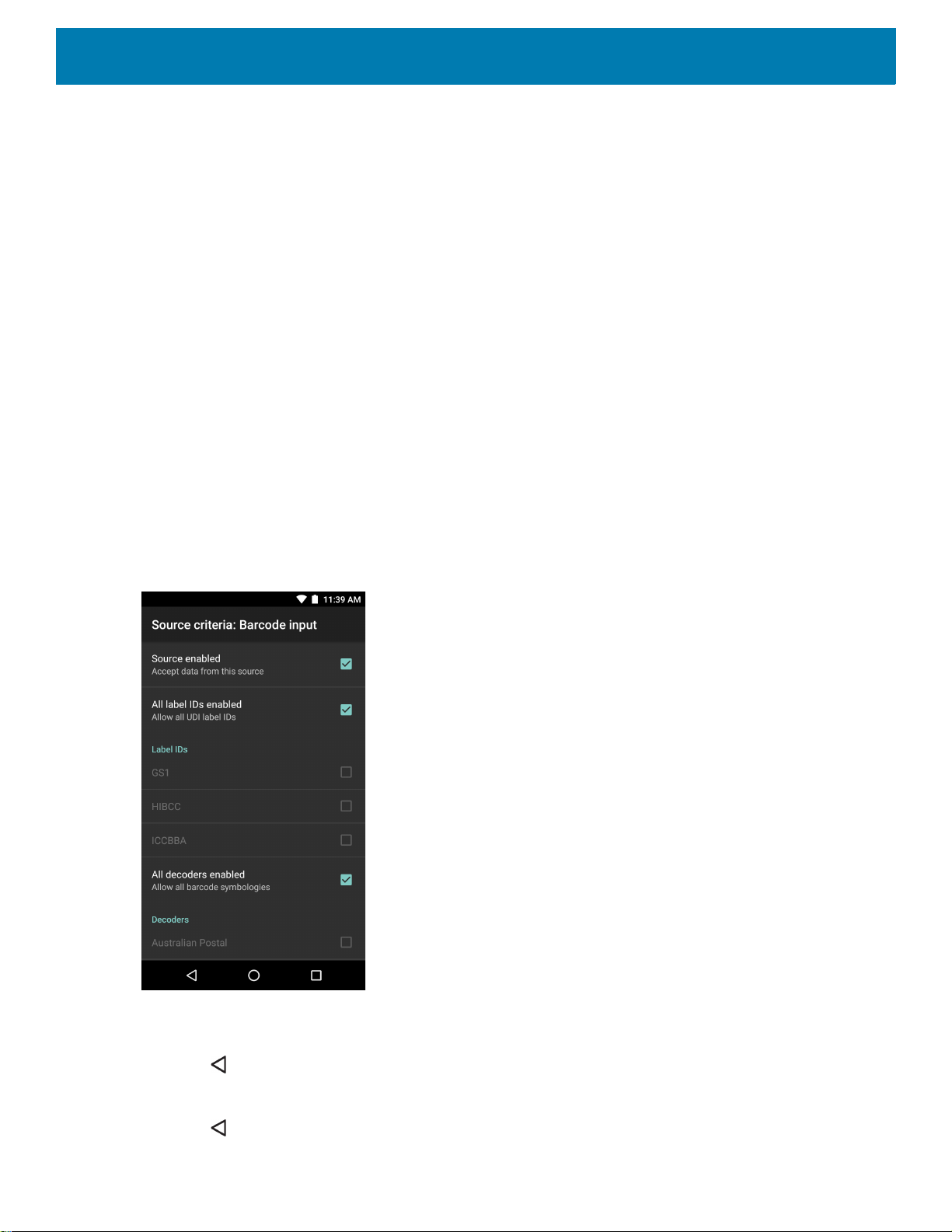
DataWedge
2. Touch String to check for option to specify the string that must be present in the data.
3. In the Enter the string to check for dialog box, enter the string
4. Touch OK.
5. Touch String position option to specify the position of the string specified in the String to check for
option. The ADF rule is only applied if the specific string in String to check for is found at the specified
String position location (zero for the start of the string).
6. Touch the + or - to change the value.
7. Touch OK.
8. Touch String length option to specify a length for the received data. The ADF rule only applies to the
barcode data with that specified length.
9. Touch the + or - to change the value.
10.Touch OK.
11.Touch Source criteria option to associate an input device to an ADF rule. The ADF rule only applies to
data received from associated input devices.
12.Touch Barcode input. Options vary depending upon the device configuration.
13.Touch the Source enabled checkbox to accept data from this source.
Figure 65 Barcode Input Screen
14.For general barcode inputs, touch the All decoders enabled checkbox to select all barcode symbologies.
Deselect the All decoders enabled checkbox to individually select the symbologies.
15.Touch until the Rule screen appears.
16.If required, repeat steps to create another rule.
17.Touch until the Rule screen appears.
96
Page 97
DataWedge
Defining an Action
NOTE: By default the Send remaining action is in the Actions list.
1. Touch .
2. Touch New action.
3. In the New action menu, select an action to add to the Actions list.
4. Some Actions require additional information. Touch the Action to display additional information fields.
5. Repeat steps to create more actions.
6. Touch .
7. Touch .
Deleting a Rule
1. Touch and hold on a rule until the context menu appears.
2. Touch Delete rule to delete the rule from the Rules list.
NOTE: When there is no rule available for ADF plug-in or all rules are disabled, DataWedge passes decoded data to the
output plug-in without processing the data.
Order Rules List
NOTE: When there are no rules defined, ADF passes the captured data through as is. In contrast, when rules are defined
but all are disabled, ADF does not pass any captured data through.
Rules are processed in top-down order. The rules that are on top of the list are processed first. Use the icon
next to the rule to move it to another position in the list.
Table 6 ADF Supported Actions
Type Actions Description
Cursor
Movement
Skip ahead Moves the cursor forward by a specified number of characters.
Enter the number of characters to move the cursor ahead.
Skip back Moves the cursor back by a specified number of characters. Enter
the number of characters to move the cursor back.
Skip to start Moves the cursor to the beginning of the data.
Move to Moves the cursor forward until the specified string is found. Enter
the string in the data field.
Move past a Moves the cursor forward past the specified string. Enter the string
in the data field.
97
Page 98

DataWedge
Table 6 ADF Supported Actions (Continued)
Type Actions Description
Data
Modification
Data
Sending
Crunch spaces Remove spaces between words to one and remove all spaces at
the beginning and end of the data.
Stop space crunch Stops space crunching. This disables the last Crunch spaces
action.
Remove all spaces Remove all spaces in the data.
Stop space removal Stop removing spaces. This disables the last Remove all spaces
action.
Remove leading zeros Remove all zeros at the beginning of data.
Stop zero removal Stop removing zeros at the beginning of data. This disables the
previous Remove leading zeros action.
Pad with zeros Left pad data with zeros to meet the specified length. Enter the
number zeros to pad.
Stop pad zeros Stop padding with zeros. This disables the previous Pad with zeros
action.
Pad with spaces Left pad data with spaces to meet the specified length. Enter the
number spaces to pad.
Stop pad spaces Stop padding with spaces. This disables the previous Pad with
spaces action.
Replace string Replaces a specified string with a new string. Enter the string to
replace and the string to replace it with.
Stop all replace string Stop all Replace string actions.
Send next Sends the specified number of characters from the current cursor
position. Enter the number of characters to send.
Send remaining Sends all data that remains from the current cursor position.
Send up to Sends all data up to a specified string. Enter the string.
Send pause Pauses the specified number of milliseconds before continuing the
next action. Enter the amount of time in milliseconds.
Send string Sends a specified string. Enter the string to send.
Send char Sends a specified ASCII/ Unicode character. Enter a character
value. The maximum Unicode character value can be entered is
U-10FFFF (= 1114111 in decimal).
Deleting an Action
1. Touch and hold the action name.
2. Select Delete action from the context menu.
ADF Example
The following illustrates an example of creating Advanced Data Formatting:
When a user scans a barcode with the following criteria:
• Code 39 barcode.
98
Page 99

DataWedge
• length of 12 characters.
• contains 129 at the start position.
Modify the data as follows:
• Pad all sends with zeros to length 8.
• send all data up to character X.
• send a space character.
To create an ADF rule for the above example:
1. Swipe up from the bottom of the screen and touch .
2. Touch Profile0.
3. Under Keystroke Output, touch Advanced data formatting.
4. Touch Enable.
5. Touch Rule0.
6. Touch Criteria.
7. Touch String to check for.
8. In the Enter the string to check for text box, enter 129 and then touch OK.
9. Touch String position.
10.Change the value to 0.
11.Touch OK.
12.Touch String length.
13.Change value to 12.
14.Touch OK.
15.Touch Source criteria.
16.Touch Barcode input.
17.Touch All decoders enabled to disable all decoders.
18.Touch Code 39.
19.Press three times.
20.Touch Actions.
21.Touch and hold on the Send remaining rule until a menu appears.
22.Touch Delete action.
23.Touch .
24.Touch New action.
25.Select Pad with zeros.
26.Touch the Pad with zeros rule.
99
Page 100
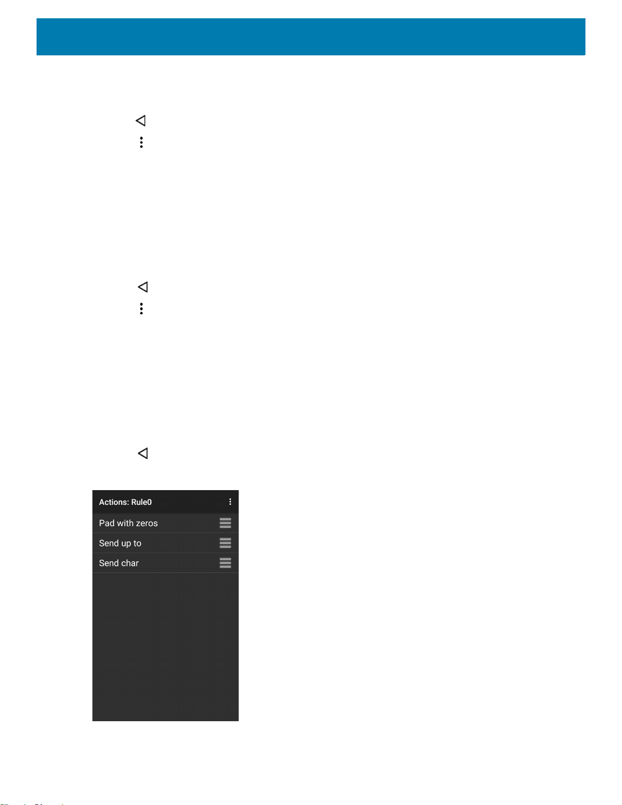
27.Touch How many.
28.Change value to 8 and then touch OK.
29.Press .
30.Touch .
31.Touch New action.
32.Select Send up to.
33.Touch Send up to rule.
34.Touch String.
35.In the Enter a string text box, enter X.
36.Touch OK.
37.Touch .
38.Touch .
39.Touch New action.
DataWedge
40.Select Send char.
41.Touch Send char rule.
42.Touch Character code.
43.In the Enter character code text box, enter 32.
44.Touch OK.
45.Touch .
Figure 66 ADF Sample Screen
46.Ensure that an application is open on the device and a text field is in focus (text cursor in text field).
100
 Loading...