

Page 1

AP 7181 ACCESS POINT
INSTALLATION GUIDE
Page 2

2 AP 7181 Access Point
Zebra and the Zebra head graphic are registered trademarks of ZIH Corp. The Symbol logo is a registered
trademark of Symbol Technologies, Inc., a Zebra Technologies company.
© 2015 Symbol Technologies, Inc.
Page 3

Installation Guide 3
Introduction.................................................................................................................................................................. 4
Document Conventions................................................................................................................................................ 4
Package Contents........................................................................................................................................................ 4
Hardware Installation.................................................................................................................................................. 5
Precautions............................................................................................................................................................ 5
Deployment Guidelines.......................................................................................................................................... 6
Installation Methodology....................................................................................................................................... 6
Grounding Requirements....................................................................................................................................... 6
Ethernet and Lightning Protection.................................................................................................................... 7
Grounding Hardware and Connections............................................................................................................ 8
Minimum Installation Requirements.................................................................................................................... 11
Access Point Placement....................................................................................................................................... 11
Site Surveys................................................................................................................................................... 11
Root Node Placement..................................................................................................................................... 11
Non Root Node Placement............................................................................................................................. 12
Mounting Locations....................................................................................................................................... 13
Device Deployment Height............................................................................................................................. 13
Antenna Options.................................................................................................................................................. 13
Power Options...................................................................................................................................................... 13
Power Cables................................................................................................................................................. 14
Mounting an AP 7181........................................................................................................................................... 15
Pole Mounted Installations............................................................................................................................ 15
Installing an AP 7181............................................................................................................................................ 15
AP 7181 Connections and Ports...................................................................................................................... 16
LED Status Indicator Panel............................................................................................................................. 18
Removing the AP 7181 Kit from the Shipping Container...................................................................................... 19
Staging the AP 7181 Prior to Installation.............................................................................................................. 21
Field Installation................................................................................................................................................... 27
Bottom Mount Installation............................................................................................................................. 27
Top Mount Installation................................................................................................................................... 35
Remote Panel Antenna Installation................................................................................................................ 42
Preparing the AP 7181 for Remote Panel Antenna Installation....................................................................
.. 44
Installing the Remote Panel Antenna............................................................................................................. 47
Installing the Blank Antenna Panel................................................................................................................ 49
Basic Access Point Configuration.............................................................................................................................. 52
Regulatory Information.............................................................................................................................................. 63
Support...................................................................................................................................................................... 68
Symbol Technologies End-User Software License Agreement................................................................................. 69
Page 4
4 AP 7181 Access Point
!
Introduction
The AP 7181 is a wireless broadband data system that uses mesh networking technology to support wide-area
broadband data coverage. The system offers both 2.4 GHz 802.11b/g/n and 5.x GHz 802.11n Wi-Fi client access
with 2.4 GHz 802.11 b/g/n and 5.x GHz 802.11a/n meshing. The dual-band system supports industry standard client
devices and features easily deployed fixed infrastructure nodes.
The AP 7181 is also designed to meet the needs of large outdoor networks. The network can be configured and
managed for optimal performance using the WiNG management UI.
Document Conventions
The following graphical alerts are used in this document to indicate notable situations.
NOTE Tips, hints, or special requirements that you should take note of.
CAUTION Care is required. Disregarding a caution can result in data loss or equipment
malfunction.
WARNING! Indicates a condition or procedure that could result in personal injury or equipment
damage.
Package Contents
The AP 7181 ships with the following:
• AP 7181 Access Point (assembled with mounting yoke attached)
• Power cable
• Optional accessories (in a separate box inside the AP 7181 shipping container)
• AP 7181 Access Point Installation Guide (this document)
Page 5

Installation Guide 5
!
Hardware Installation
An AP 7181 Access Point installation includes mounting the Access Point, connecting the Access Point to the
network, and applying power. Installation procedures vary for different environments.
Precautions
Before installing an AP 7181 Access Point, verify the following:
• Become familiar with grounding requirements
• The grounding cable for an AP 7181 must be a #8 gauge (10 mm) wire cross section and use a ring lug
that will fit the M5 grounding screw on the bottom of the unit
• Verify the environment has a continuous temperature range between -40° C to 55° C
AP 7181 Access Points must be installed by trained professionals familiar with RF planning and regulatory limits
defined by the regulatory bodies of the country where the devices are being deployed. All common precautions for
grounding and Electrostatic Discharge (ESD) protection should be observed during deployment and installation. AP
7181 Access Points are designed to be installed outdoors and must be installed such that no harmful interference
results from device operation.
CAUTION All device wiring must comply with the National Electric code (NEC) or regulations
and procedures defined by the regulatory bodies of the country or region where the
devices are being deployed. All local building and structure codes must be
observed.
WARNING! Strictly observe the following safety precautions during the AP 7181 installation
procedure.
• Installations must be performed by professionals who are properly trained and certified,
• Avoid contact with overhead power lines,
• Take precautions to avoid injury from falling tools and equipment. Crews should wear hard hats in and
around the installation work site.
• Be aware of vehicular traffic in and around the installation work site.
• Do not hold any component containing a radio such that the antenna is very close to or touching any
exposed parts of the body, especially the face or eyes, while transmitting.
• Do not operate a portable transmitter near unshielded blasting caps or in an environment where
explosives are present unless the transmitter is especially certified for such use.
Page 6
6 AP 7181 Access Point
!
Deployment Guidelines
Observe the following recommended guidelines to help ensure a successful network deployment:
• Mounting height for network devices should not exceed 30 to 35 feet. Mounting height should vary to
accommodate the topography of the deployment area, foliage, and other obstructions.
• Devices can be deployed using either the Bottom Mount Installation or the Top Mount Installation
procedure.
• Point-to-Point (PTP (Slave)) or Point-to-Multipoint (PMP (SM)) nodes providing backhaul should be oriented
to point away from AP 7181 antenna panels.
• Custom stand-off brackets should be used as required to provide adequate pole separation in an effort to
minimize reflective received power.
• Line of Sight (LoS) guidelines should be given special consideration whenever devices are not installed in
a straight line, such as deploying devices on alternating sides of a roadway.
• Ensure all root nodes are deployed with LoS to the wireless backhaul cluster points.
Installation Methodology
Consideration of the order in which units are installed when deploying an AP 7181 wireless network can ensure a
more stable and functional network. The PTP backhaul layer should be deployed first. Next, deploy all nodes for the
PMP Access Point distribution layer. Next, deploy root node nodes along with PMP Subscriber Modules (SMs) such
that backhaul and network connectivity can be verified or corrected. Finally, deploy all Mesh Point wireless nodes
in order of the least to most hops (1 hop nodes first, followed by 2 hop nodes, etc.).
Grounding Requirements
The grounding cable for an AP 7181 must be a #8 gauge (10 mm) wire cross section and use a ring lug that fits the
M5 grounding screw on the bottom of the unit.
CAUTION It is required all root and portal nodes be adequately grounded. In addition, all root
nodes and portals using the Ethernet port or attached devices (e.g. a camera) must
not only be grounded, but they should also include surge suppression for network
reliability. This is particularly important for network configurations with a public
safety component.
Page 7
Installation Guide 7
Ethernet and Lightning Protection
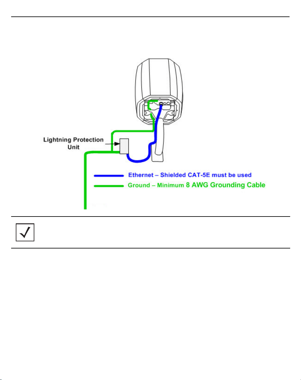
When installing an AP 7181 root node with a direct connection between the shielded CAT-5E Ethernet and the wired
network, lightning protection should be used on all shielded CAT-5E Ethernet connections.
NOTE Lightning damage is not covered under the conditions of a standard product warranty.
When installed correctly, LPUs provide the best protection from the harmful effects of
lightning. Observe all regional and national codes that apply to grounding for lightning
protection.
Page 8
8 AP 7181 Access Point
Grounding Hardware and Connections
The grounding cable for an AP 7181 must be a #8 gauge (10 mm) wire cross section and use a ring lug that fits the
M5 grounding screw on the bottom of the unit (see
Grounding Hardware and Connections).
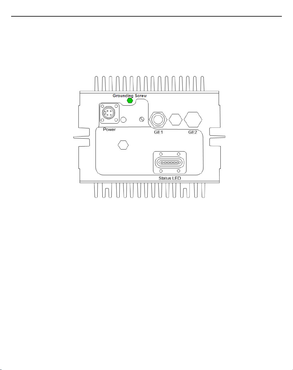
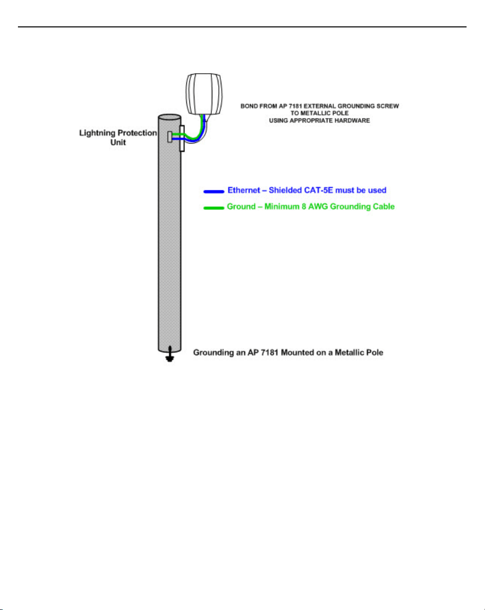
The grounding screw is shown below in green:
When connecting the grounding cable to the unit, tighten the grounding screw from 21.9 - 29.2 inch pounds (lbf-in).
Page 9
Installation Guide 9
Access points mounted on a metallic pole should be grounded as shown in the following figure:
Page 10
10 AP 7181 Access Point
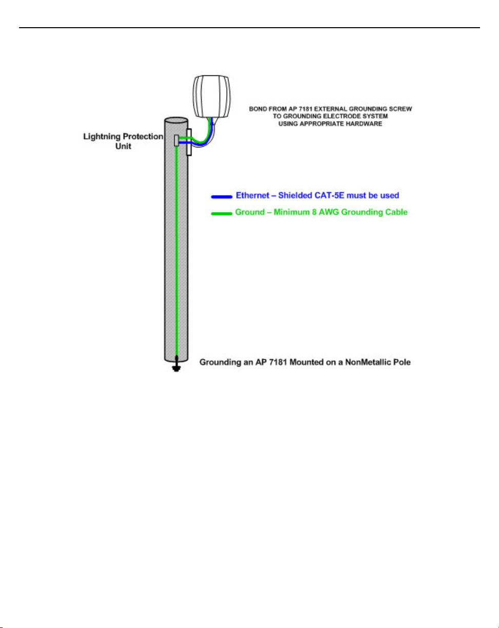
Access points mounted on a nonmetallic pole should be grounded as shown in the following figure:
When grounding a unit installed on a non-metallic pole, a ground conductor and rod is required. This requirement
should be factored into the project deployment costs, particularly if the equipment must be installed by a utility
company.
When grounding a unit installed on a wooden pole, a ground conductor and rod is required. This requirement should
be factored into the project deployment costs, particularly if the equipment must be installed by a utility company.
Page 11

Installation Guide 11
Minimum Installation Requirements
The minimum requirements for installing an AP 7181:
• AP 7181 Access Point
• Power cable (flying leads)
• Standard Ethernet cable
• Yoke (attached)
• 22 mm socket and driver to remove port caps
• #6 metric Allen wrench to remove the yoke
Access Point Placement
Typically, roadways in the deployment area become main arteries for the wireless mesh network. Roadways can
provide LoS coverage over large distances between root nodes and non root APs.
Site Surveys
A site survey is recommended prior to installing an Access Point. A thorough site survey must include a visit to the
customer site to identify the characteristics of the coverage area, including availability of electrical distribution for
power sources and the location of existing network infrastructure.The site survey should also include preliminary
WLAN measurements to identify candidate AP locations
When scheduling a visit to conduct a site survey, request access to wiring closets, adjacent floors, and other
locations that may require special permission.
Root Node Placement
When planning for root node placement:
• Identify Root node wireless backhaul technology (Point-to-Point (PTP), Point-to-Multipoint (PMP))
• Identify Ethernet or fiber optic backhaul
• Identify Root node locations
• Obtain all required permits and/or lease agreements
• Verify that power is available at each potential node deployment location
• Give careful consideration to the fact that Root nodes with a wireless backhaul usually backhaul traffic to
a cluster point (i.e. PMP Canopy)
• Wireless backhaul clusters can be on towers, rooftops, etc.
• Ensure that all Root nodes are deployed with LoS to cluster points
When installing an AP 7181 root node that has its Shielded CAT-5E Ethernet directly connected to the wired
network, lightning protection should be used on all Shielded CAT-5E Ethernet connections. An outdoor rated
Lightning Protection Unit kit such as the HyperLink AL-CAT6HPJW Lightning Protector should be used.
Page 12

12 AP 7181 Access Point
Non Root Node Placement
The same guidelines as Root nodes apply to Non Root nodes with the exception of a backhaul requirement
The placement of Non Root nodes will depend heavily on the RF network design. Consider the guidelines for
optimizing wireless network performance when identifying potential mounting sites.
In addition, consider the following when planning for Non Root node placement:
• Light Poles, Utility Poles, or Traffic Poles
• Obtain all required supplemental agreements from local governments and utilities
• Obtain a generic mounting agreement that is not specify specific poles, since installation locations
may need to be modified during deployment
• Plan for AC power usage of 84 watts average, 126 watts peak
• The AP 7181 is rated for wind loading of up to160 miles per hour and 30 pounds per square foot.
• Ensure that proper grounding can be established
• The grounding cable for an AP 7181 must be a #8 gauge (10 mm) wire cross section and use a ring lug
that will fit the M5 grounding screw on the bottom of the unit
• Rooftops and Towers
• May require lease agreements
• Identify Access Point locations based on optimal communication with the Root nodes
• Non root node placement will be dependent on asset availability, terrain, etc.
• Ensure that nodes are placed at the same height
• Build the network outward from each root node, from least to greatest number of hops
As with Root node nodes, it should be noted it is incumbent upon the customer to obtain the required pole
attachment agreements for devices to be installed on traffic / utility poles. Obtaining the agreements can be a
lengthy process, so ample lead time must be allowed.
The potential pole locations should be logged with GPS to obtain accurate coordinates. Also log any identifying
numbers on the pole so this information can be provided to the appropriate utility agency. Alternate mounting
locations should also be identified in the event that your initial request is denied.
Specialized brackets may be required for attaching devices to decorative light poles and these brackets may have
to be custom fabricated. In this case, allow enough lead time for ordering the proper equipment.
Also consider any requirements to coordinate requests with multiple utility agencies within the same community.
Verify light pole selections have power available continuously and the power source is within the operational range
of the device being connected.
Page 13

Installation Guide 13
Mounting Locations
To avoid distortion of the RF pattern, device locations should be chosen such that the AP 7181 ADvanced Element
Panel Technology (ADEPT) antenna panels are at least 30 inches from any nearby metal poles and not co-located
or operating in conjunction with any other antenna or transmitter.The antenna panels must also have a separation
distance of at least 2 meters from anyone who may come into proximity of the AP 7181.
Device Deployment Height
AP 7181 nodes are typically mounted at a height of 30 to 35 feet. Ensure neighboring nodes are mounted at or near
the same device height.
Excessive height should be avoided since this may result in increased congestion and interference in dense RF
environments. This is especially true for the 2.4 GHz band.
Nodes deployed with too great a difference in height or too close to each other may not mesh properly.
Always consider these general guidelines for device deployment height:
• Maintain a typical deployment height of 30 to 35 feet
• For optimum performance, ensure that devices are oriented to have LoS to all neighboring devices
• Locate root nodes which support Wireless Backhaul so that they have LoS to Backhaul clusters or PTP
locations, such as towers
Antenna Options
The AP 7181 features an integrated ADvanced Element Panel Technology (ADEPT) antenna system designed to take
full advantage of the 802.11n radios. No other antennas are supported.
Power Options
Details of the power sourcing equipment for the AP 7181 should be handled by a professional installer. The
requirements for deploying the system are:
• Over current protection device with a maximum rating of 20 Amps.
• AP 7181 AC Model - 100-240 VAC input capable of sourcing 180 watts.
• AP 7181 DC Model - Nominal 48 volt power source (41-58 VDC) capable of sourcing 150 watts and battery
floating voltage should not exceed 60 VDC
Page 14
14 AP 7181 Access Point
!
!
Power Cables
Flying lead power cables are available based on the country of operation.
Four Wire AC Right Angle Power Cable
(North America and International)
Three Wire AC Power Cable
(International)
Two Wire DC Power Cable
(North America and International)
CAUTION Never plug a power cable wired to a power source for an AC unit into a DC unit.
Black (Line)
White (Neutral)
Red (Unused)
Green/Yellow (Ground)
Brown (Line)
Blue (Neutral)
Green/Yellow (Ground)
Black (Negative)
Red (Positive)
If the units will be plugged directly into an electrical wall outlet, power plug adapters are available for North
America, Europe, and Australia.
CAUTION Do not use the connector on the power cables for interrupting current. Never
actively plug or unplug the connector while the cable is energized.
Page 15
Installation Guide 15
Mounting an AP 7181
The AP 7181 Access Point is designed for outdoor installations. All hardware installations should be performed by
a professional installer.
Devices can be deployed using either the
Pole Mounted Installations
Bottom Mount Installation or the Top Mount Installation procedure.
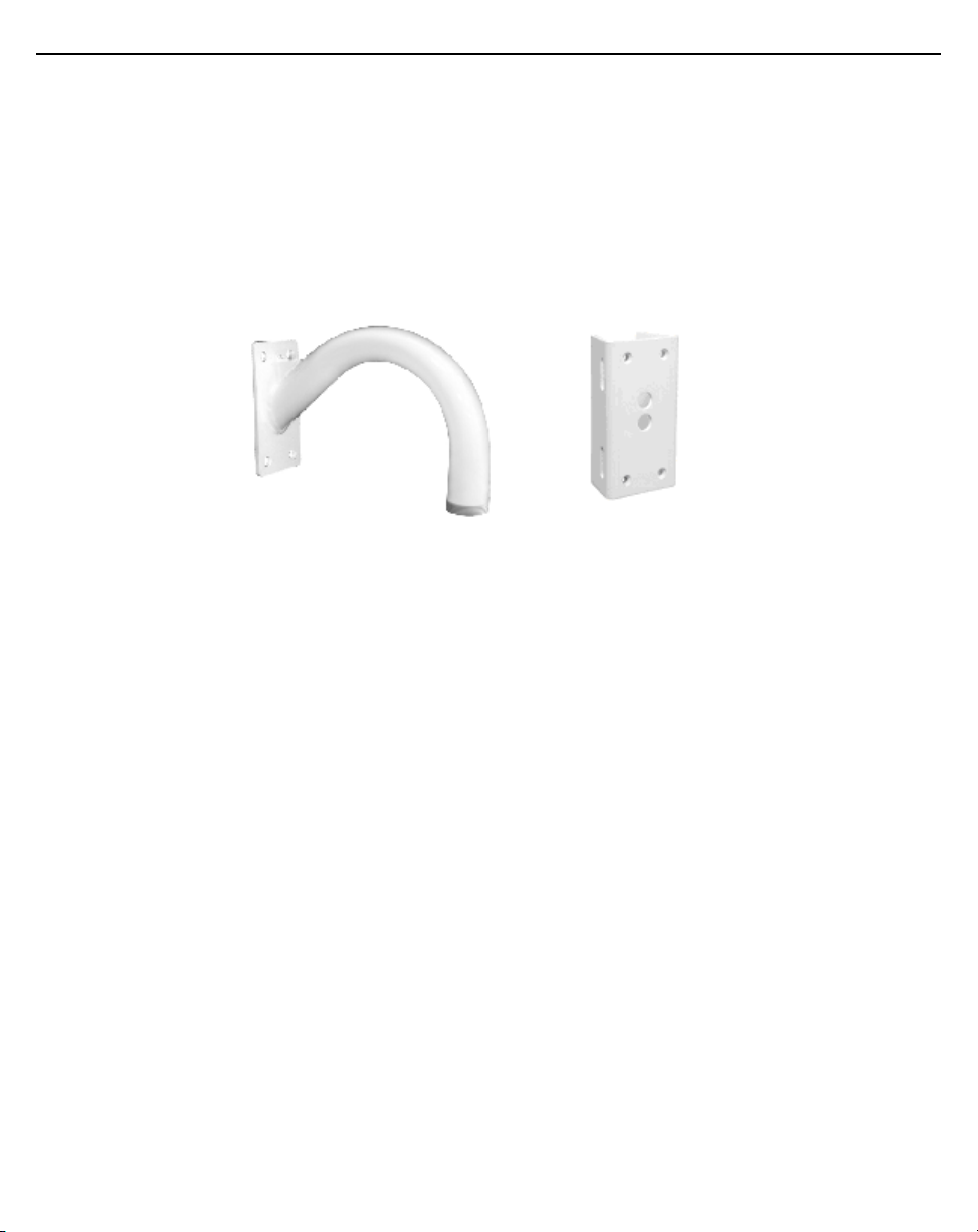
The optional wall gooseneck can also be used with the pole adapter for pole mounting.
The wall gooseneck dimensions are 10x12x6 inches and it weighs 4 pounds. The pole adapter dimensions are
4x2.62x7 inches and it weighs 3 pounds.
The gooseneck attaches to the yoke, which can be attached to the top or the bottom of the AP 7181. Secure the
gooseneck and adapter to the pole with the threaded portion pointing either up or down using band clamps.
If using a bottom mount, drill a 1/2 inch diameter hole at the lowest point on the bend to allow water to drain from
the gooseneck.
Installing an AP 7181
The following guidelines and procedures should be observed when installing an AP 7181 Access Point.
The following is a list of the minimal tool set required to install an AP 7181 device:
• 24 mm socket and driver - for cable gland
• 22 mm socket and driver - for GE1 and GE2 port caps
• 19 mm socket and driver - for console port cap
• 21 mm socket and driver - for set screw
• 8 mm socket and driver - for grounding screw
• 6 mm Allen wrench bit - for mounting bracket (yoke)
• T27 Torx bit - for the radome antenna panels and sun shields
• Torque screwdriver - for the radome antenna panels and sun shields
• Torque wrench
• Adjustable wrench
Page 16
16 AP 7181 Access Point
• Standard level
• Anti-seize lubricant
You may also need a Phillips screw driver and a 2.5 mm Allen wrench.
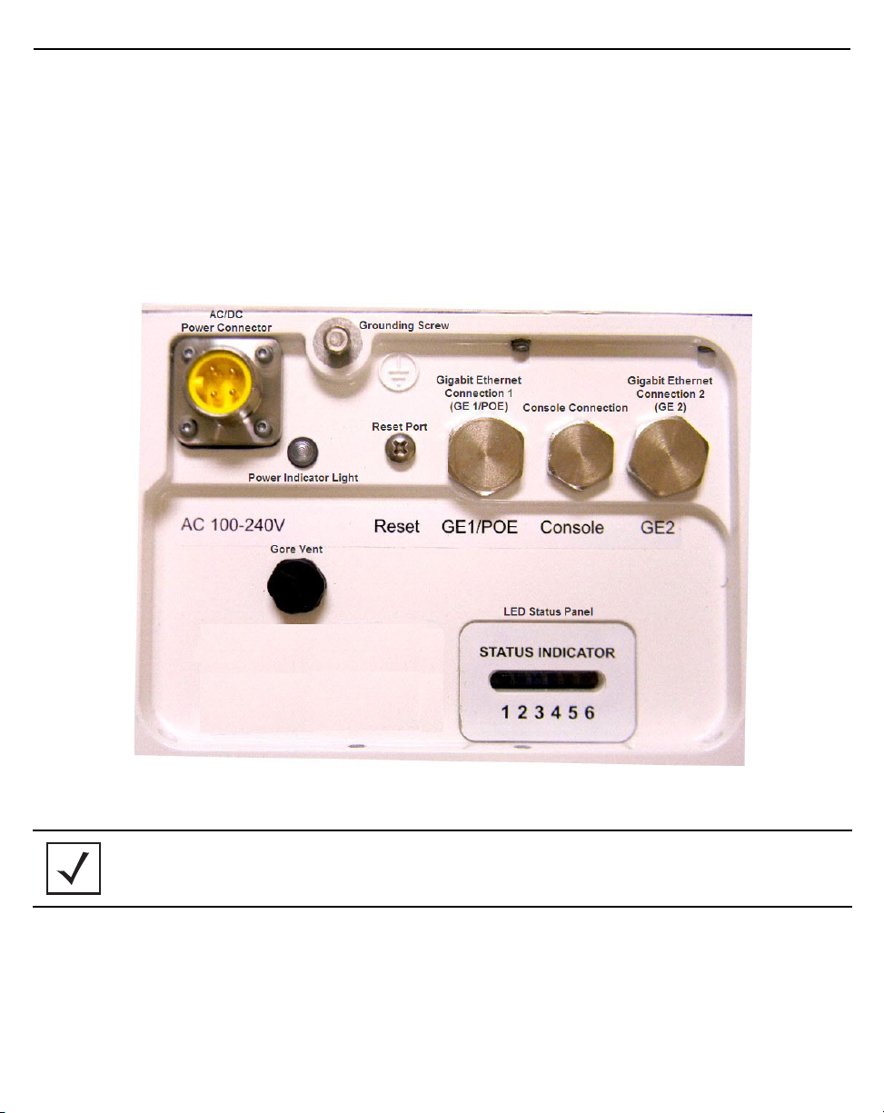
AP 7181 Connections and Ports
The power cable, grounding connections, power indicator light, Ethernet ports, and LED status panel on the bottom
the AP 7181 are shown in the figure below:
NOTE The grounding cable for an AP 7181 must be a #8 gauge (10 mm) wire cross section
and use a ring lug that will fit the M5 grounding screw on the bottom of the unit.
Page 17
Installation Guide 17
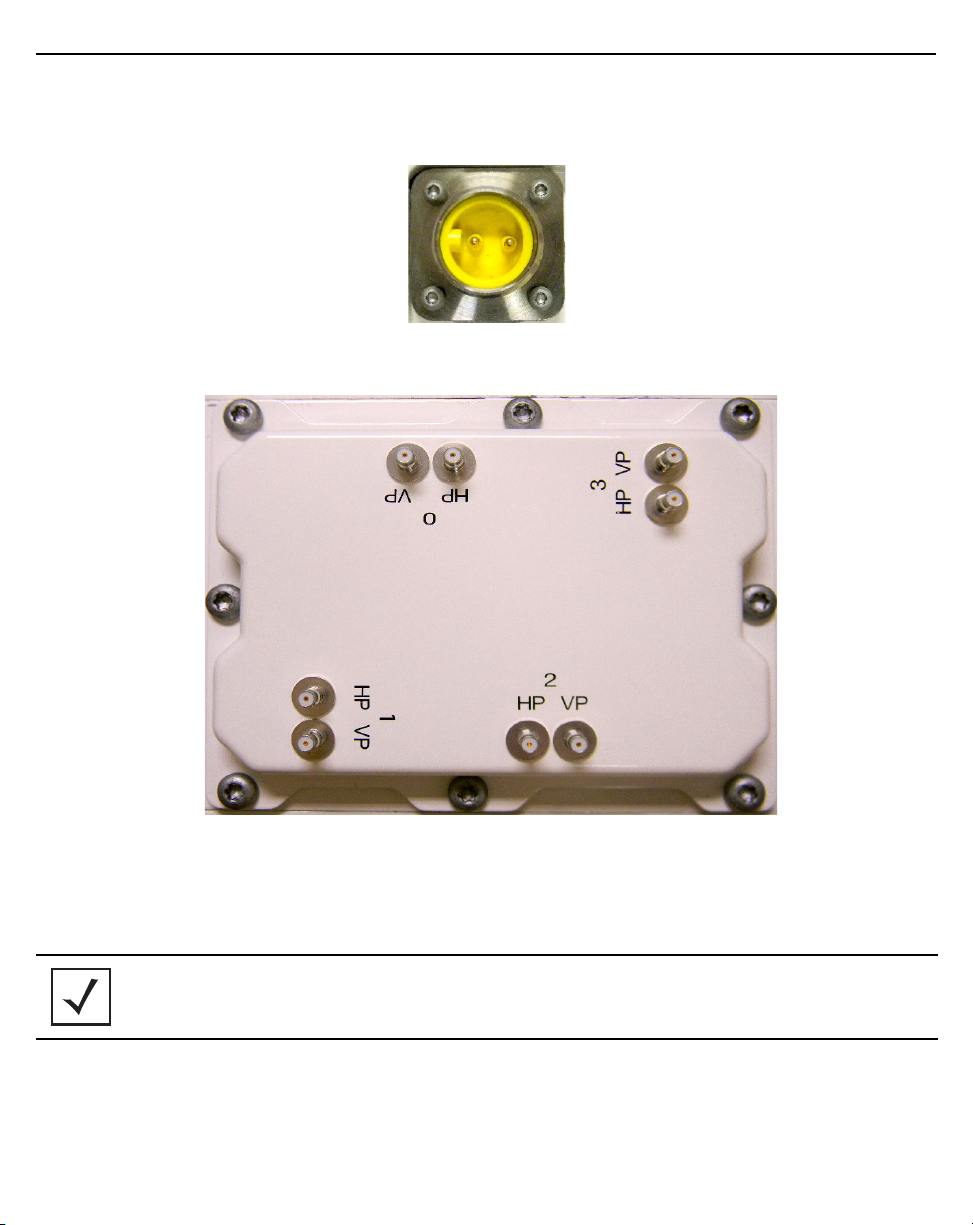
The two pin DC power connector (phase-in) is shown below. All other connections, ports, and the LED status panel
are the same.
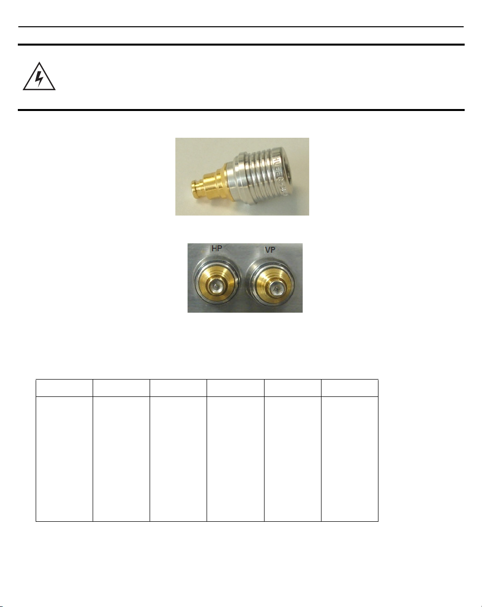
The horizontal (HP) and vertical (VP) connectors for the antenna cables are located on the top of the AP 7181.
All radome antenna panel cables are labeled as HP or VP. Attach each cable to the corresponding connector when
performing a remote panel installation or any other procedure which requires attaching antenna cables to the
connectors.
NOTE The connectors on the AP 7181 are Ingress Protection 67 (IP67) rated. No additional
weatherproofing precautions are required.
Page 18
18 AP 7181 Access Point
WARNING! When disconnecting the antenna cables from the unit or removing an antenna panel
and replacing it with a blank panel, terminators MUST be placed on the unused
horizontal and vertical connectors on the top of the unit. The terminators on the AP
7181 are Ingress Protection 68 (IP68) rated. No additional weatherproofing
precautions are required.
LED Status Indicator Panel
There are six LEDs on the AP 7181 which can be viewed through the light pipes on the bottom of the unit. The LEDs
have the following display characteristics and functionality:
LED 1 LED 2 LED 3 LED 4 - 5 GHz LED 5 - 2.4 GHz LED 6
Blinking Red
indicates
booting. Solid
Red defines a
failure
condition.
White
defines
normal
operation.
Green
defines
normal GE1
operation.
Yellow
defines a
collision.
Green
defines
normal GE2
operation.
Yellow
defines a
collision.
Amber
defines 5 GHz
radio as
configured.
Emerald
defines 2.4
GHz radio as
configured.
Not used.
Page 19
Installation Guide 19
!
Removing the AP 7181 Kit from the Shipping Carton
CAUTION Never lift an AP 7181 using the radome antenna panels or other plastic parts.
Always lift the unit by the yoke or metal antenna rings.
WARNING! An AP 7181 unit weighs 39 pounds. Use all appropriate cautions when lifting and
consider a two man lift when necessary.
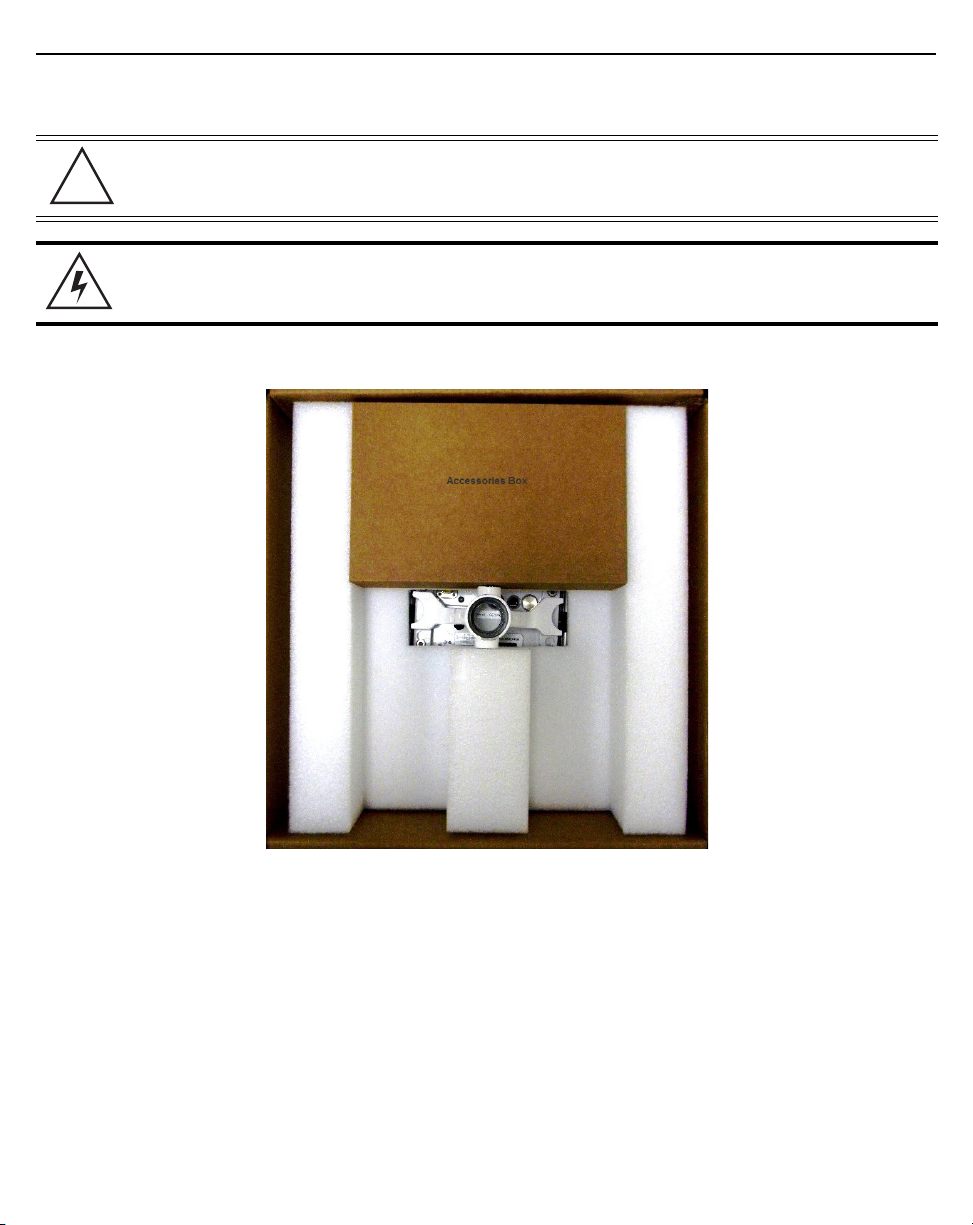
1. Open the shipping carton and remove the packaging material on the top of the Access Point.
Page 20
20 AP 7181 Access Point
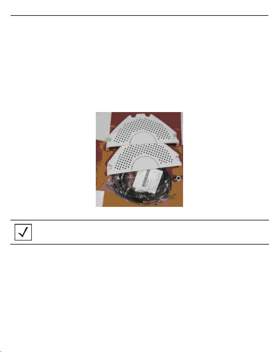
2. Remove the accessories box from the shipping carton.
In the accessories box, locate the following items:
• Weatherproof Ethernet port adaptor (cable gland) (part number: HKLN4486A)
• Waterproof Console Port Adapter (part number: HKLN4485A)
• Power Cable (part number: 30009307001, 30009308001, or 30009315002)
• Sun Shields with Captive Screws (part number: HKLN4446A)
• Yoke (Mounting Bracket) (part number: HKLN4484A)
• Set Screw for Yoke (part of the complete AP 7181 kit)
NOTE Only one set screw is included with each AP 7181 kit. If a second set screw is required,
purchase an M14x2.0, 20mm stainless steel Hexagonal screw.
3. Open the plastic bag covering the unit.
4. Roll the plastic bag to the bottom of the shipping carton. Using the yoke or antenna ring, carefully remove
the unit from the box. This method prevents damage to the antenna assembly.
Page 21
Installation Guide 21
!
Staging the AP 7181 Prior to Installation
WARNING! An AP 7181 Access Point weighs 39 pounds. Use all appropriate cautions when lifting
and consider a two man lift when necessary.
1. Place the Access Point on a solid surface with the yoke facing up.
CAUTION Never lift an AP 7181 using the radome antenna panels or other plastic parts.
Always lift the unit by the yoke or metal antenna rings.
2. Using the 6mm Allen wrench, loosen the Allen head bolts to remove the yoke.
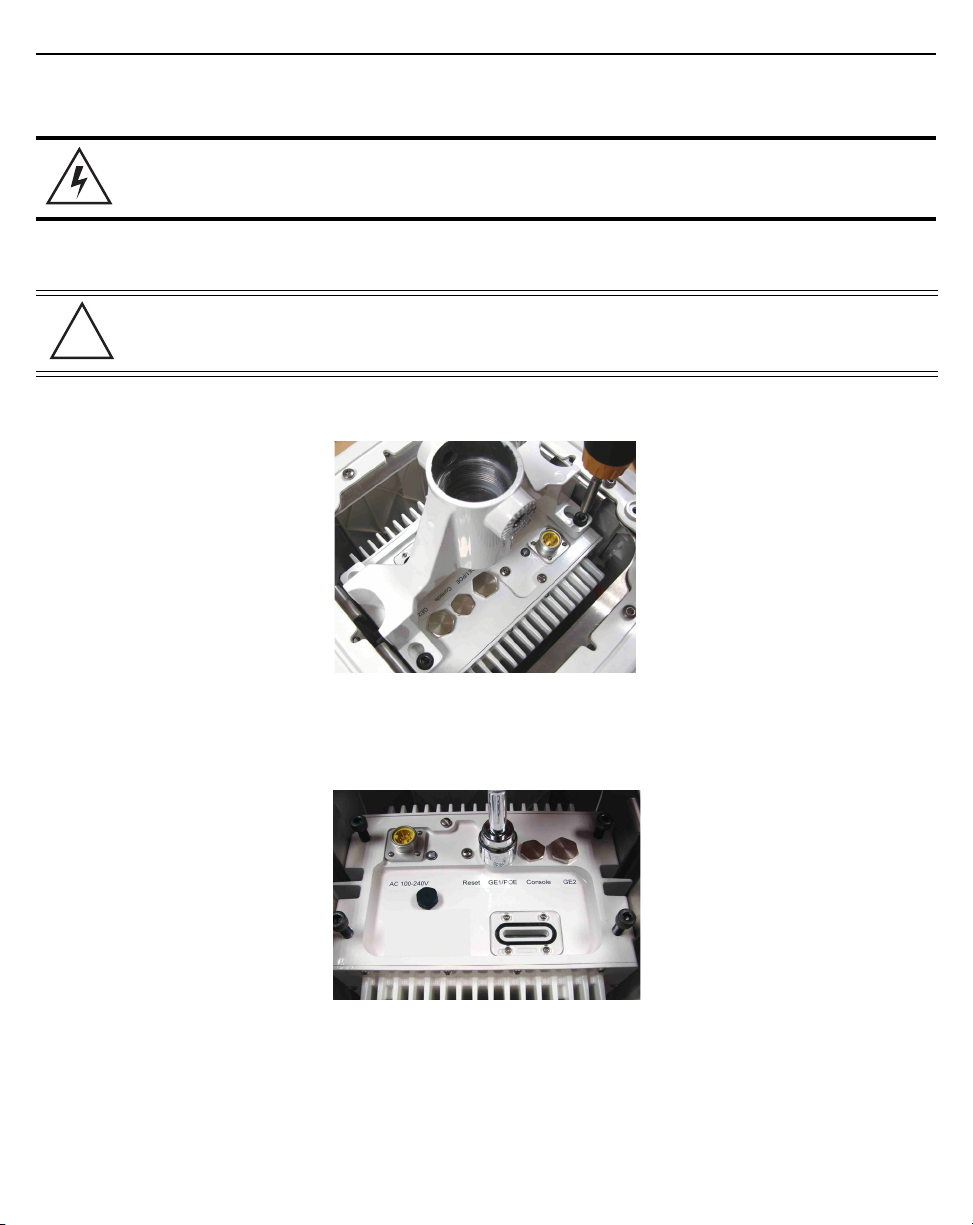
3. To gain access to the Ethernet and or console ports you will need to remove the protective caps. A 22 mm
socket is required to remove the Ethernet port caps covering Gigabit Ethernet ports GE1 and GE2. A 19 mm
socket is required to remove the console port cap (if required).
Page 22
22 AP 7181 Access Point
4. Using the 22 mm socket, remove the port caps for Gigabit Ethernet GE1 and GE2.
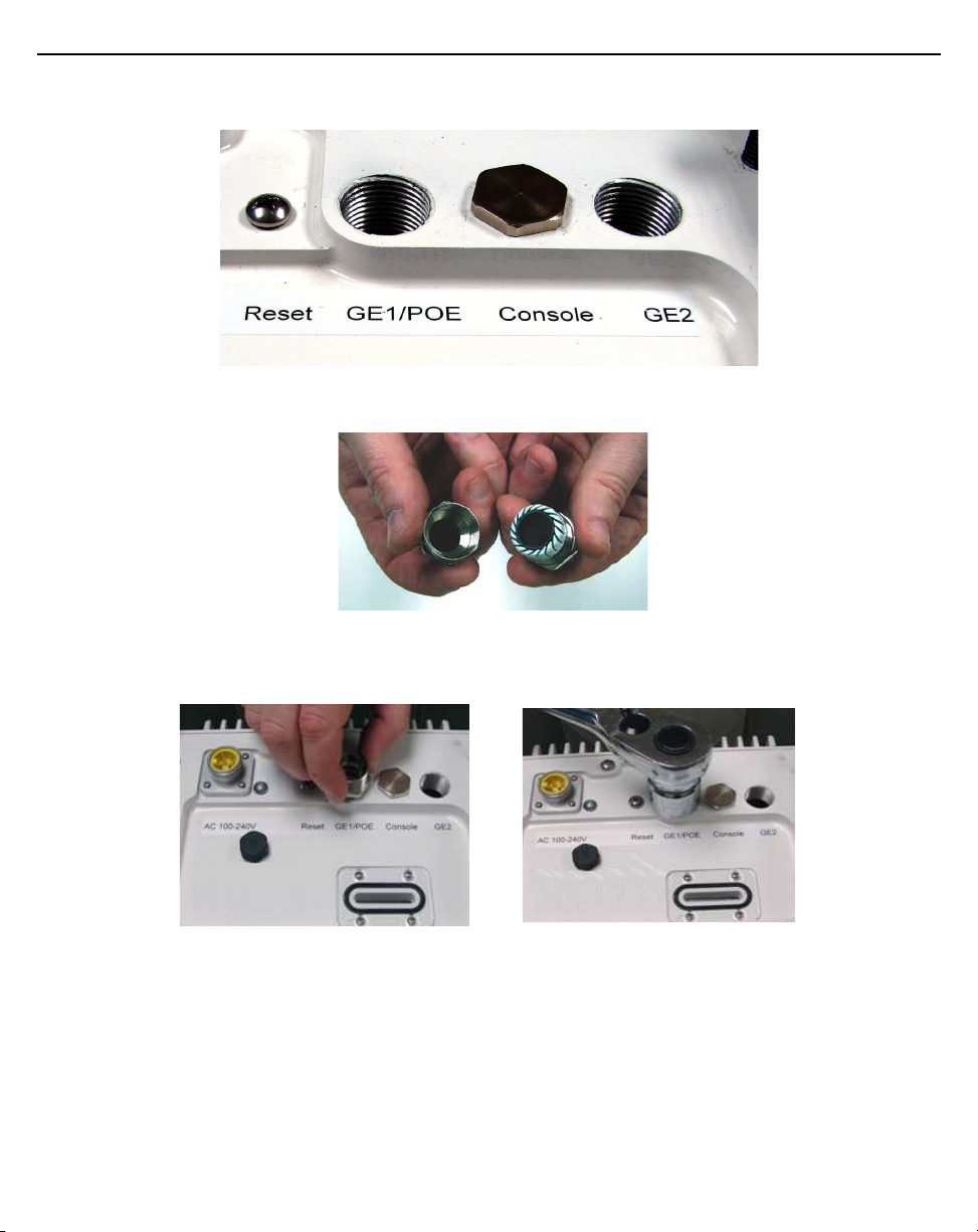
5. Remove the cap on the cable gland as shown below.
6. Carefully hand tighten the gland into Gigabit port GE1. Once the gland is snug, use a 24 mm socket to
finish tightening the gland.
Page 23
Installation Guide 23
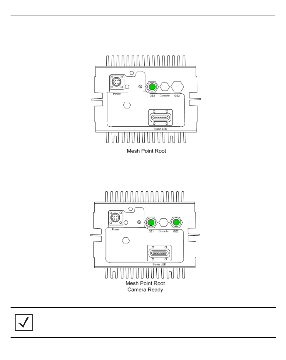
If the node is configured as a Mesh Point Root node (Mesh Point Root nodes have a direct wired
Ethernet connection to the core network or an Ethernet connection to a wireless backhaul), a cable gland
is required for Gigabit Ethernet port GE1.
If the Mesh Point Root node has an external device attached (e.g. surveillance camera), an additional
cable gland is required for Gigabit Ethernet port GE2 (make sure the WAN port GE2 has been configured
to permit an attached external device during the configuration process).
NOTE The AP 7181 supports 802.af compliant Power over Ethernet (PoE) on Ethernet port GE1,
and can provide power to an external PoE capable device such as a surveillance
camera. PoE is auto sensing and is enabled when the AP 7181 senses a PoE capable
device.
Page 24
24 AP 7181 Access Point
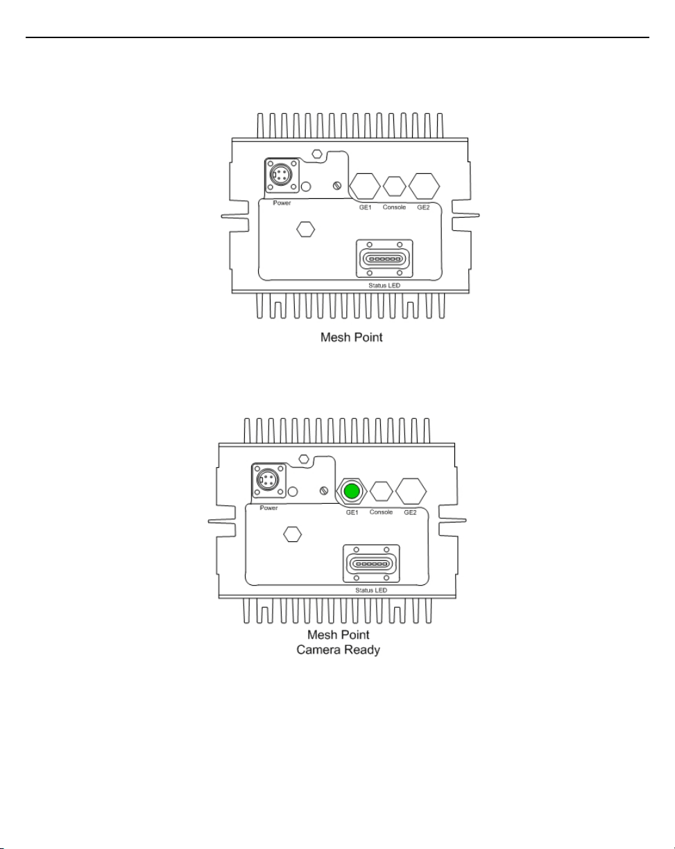
If the device being staged is a Mesh Point node (no wired connection to the core network) and no
external device is going to be attached then no cable glands are required.
If the Mesh Point node is going to have an external device attached (e.g. surveillance camera), a cable
gland is required for Gigabit Ethernet port GE1.
Page 25

Installation Guide 25
7. Repeat the process if a second cable gland is required.
8. Attach an Ethernet cable to Gigabit Ethernet port GE2 (used with an external laptop for configuring the
unit). You also need to terminate the flying lead power cable with the proper plug (for the country of
operation) so the unit can be powered for configuration. After preparing the power cable, attach the cable
to the power port. Notice the power connector is keyed. Next configure the unit. Refer to
Point Configuration
for initial configuration of the AP 7181 Access Point.
Basic Access
Page 26

26 AP 7181 Access Point
9. Once the Access Point is configured, if the GE2 port is used to attach an external device to the AP7181,
reattach the port cap. If the GE2 port is used to attach and external device, attach the cable gland to the
GE2 port.
10. Reattach the yoke.
11. Return the unit to the shipping carton for transport to the installation site. Due to the nature of the
electronic components and antenna array, using the shipping carton is the most secure method for
transport.
Page 27

Installation Guide 27
!
Field Installation
CAUTION Observe the following precautions to avoid damage to the unit during installation:
• Only trained and qualified personnel should install this equipment
• Only a licensed electrician should install power cable / energize circuits
• All device wiring must follow the National Electric Code (NEC) or wiring requirements in the country of
installation. All location building and structure codes must be observed
• Ensure that the power source for the AP 7181 is de-energized prior to installation
WARNING! Observe the following safety precautions to avoid personal injury during installation:
• Avoid exposure to high voltage power sources
• Avoid contact with overhead power lines
• Avoid falling tools or equipment
• Be aware of vehicular traffic in the vicinity of the work area
WARNING! When disconnecting antenna cables from the unit or removing an antenna panel and
replacing it with a blank panel, terminators MUST be placed on the unused connectors
on the top of the unit. The terminators for the AP 7181 are Ingress Protection 68 (IP68)
rated. No additional weatherproofing precautions are required.
Bottom Mount Installation
The pole mount adapter (Part Number RLN6197A) will accommodate a banding strap up to 1¼ inch width. Banding
straps and the banding tool are not included when ordering the pole mount adapter. The banding straps
recommended for the pole mount adapter are 3/4 inch 201 Stainless Steel BAND-IT BAND
(www.band-it-index.com
) or better. Two bands are required for each mounting kit.
Page 28

28 AP 7181 Access Point
The pole mount adapter can be mounted to poles 3 inches to 15 inches in diameter and has a load rating of 75 lbs.
1. Attach the pole mount adapter (or other mounting bracket hardware) to the mounting asset and ensure
that the mounting bracket is level.
NOTE If using a bottom mount, drill a 1/2 inch diameter hole at the lowest point on the bend
to allow water to drain from the gooseneck.
2. Secure the gooseneck to the pole mount adapter using the 4 hex head bolts (3/8"x16"x1") included with
pole mount adapter (Part Number RLN6197A).
NOTE It is recommended to apply a small tube of anti-seize lubricant to the threads of the
gooseneck to prevent corrosion and seizing. This will facilitate the mounting process
and assure easier disassembly if the unit needs to be serviced.
3. Grasp the yoke and carefully remove the unit from the shipping carton.
4. Place the unit on a solid surface with the yoke facing up.
5. Remove the yoke and the Allen socket head screws from the bottom of the Access Point.
Page 29

Installation Guide 29
6. Attach the yoke to the gooseneck by rotating the device counter clockwise for a minimum of four turns.
WARNING! Carefully align the yoke with the mounting bracket to avoid cross threading.
7. Ensure the yoke and the mounting bracket are level.
8. Loosely attach the Allen socket head screws to the unit. Leave the screws loose enough to attach the
yoke.
Page 30

30 AP 7181 Access Point
!
9. Carefully lift the unit into position. Align the key slots for the yoke with the Allen socket head screws and
slide the yoke to the final position.
WARNING! An AP 7181 Access Point weighs 39 pounds. Use all appropriate cautions when lifting
and consider a two man lift when necessary.
10. Torque the Allen socket head screws to between 108.7 and 145.0 Inch Pounds (lbf-in).
CAUTION Ensure the Allen socket hex screws are tight and in the locked position before
releasing the full weight of the Access Point.
Page 31

Installation Guide 31
11. The set screw can now be inserted to increase stability. Tighten the set screw from 214.2 - 250.0 inch
pounds (lbf-in).
NOTE Only one set screw is included with each AP 7181 kit. If a second set screw is required,
purchase an M14x2.0, 20mm stainless steel Hexagonal screw.
12. If the AP 7181 is a Mesh Point Root node or a Mesh Point node with an external device (e.g. surveillance
camera), perform the required Ethernet cabling.
The Ethernet cable gland is optimized for cables of diameter .39 - .55 inches. Smaller diameter cables can
achieve a watertight seal if the cable gland is properly tightened during installation. It is recommended
that an outdoor UV rated shielded cable is used in AP 7181 deployments. Examples are:
• Superior Essex 04-001-55
• Best-Tronics BT-0562
In most cases, Ethernet cable is custom cut to length. After preparing the Ethernet cable and attaching
shielded RJ-45 end connectors, feed the cable through the cable gland cap and rubber insert as shown
below.
13. Insert the data cable through cable gland (i.e. the cable gland on Gigabit Ethernet port GE1).
a. Connect the RJ45 Ethernet cable to the Ethernet port.
b. Hand tighten the cap for the cable gland.
Page 32

32 AP 7181 Access Point
!
c. Using an adjustable wrench, tighten the cable grip until it fits snugly around the Ethernet cable.
d. Repeat the process for additional Ethernet connections if required.
CAUTION Observe the following precautions to avoid damage to the unit during installation:
• Only trained and qualified personnel should install this equipment
• Only a licensed electrician should install power cable / energize circuits
• All device wiring must follow the National Electric Code (NEC) or wiring requirements in the country
of installation. All location building and structure codes must be observed
• Ensure the power source for the AP 7181 is de-energized prior to installation
WARNING! Observe the following safety precautions to avoid personal injury during installation:
• Avoid exposure to high voltage power sources
• Avoid contact with overhead power lines
• Avoid falling tools or equipment
Page 33

Installation Guide 33
!
• Be aware of vehicular traffic in the vicinity of the work area
The power cable included with the AP 7181 is a flying lead cable. Most installations require the installer to install
an additional power cable.
The AP 7181 flying lead power cables are 12 feet long. The installer should splice the power cable to the AP 7181
flying lead cable in accordance to the NEC or wiring requirements in the country of operation. Only outdoor rated
power cable should be used.
CAUTION AC versions of the AP 7181 require an input voltage of 100 -240 VAC. DC versions
require an input voltage of 41-58 VDC.
14. Once the power cable has been prepared, connect the power cable to the unit.
15. The grounding cable for an AP 7181 must be a #8 gauge (10 mm) wire cross section and use a ring lug
that fits the M5 grounding screw on the bottom of the unit.
Page 34

34 AP 7181 Access Point
The grounding screw is shown below in green. When connecting the grounding cable to the unit, tighten
the grounding screw from 21.9 - 29.2 inch pounds (lbf-in).
16. Secure and conceal the cables using UV resistant tie wraps. Tie wraps should be used to secure the cables
along the gooseneck.
17. If desired, attach the sun shields to the top/bottom using the captive screws. If attaching the sun shields
to the bottom of the unit, first remove the knock out discs in the center to fit the sun shields around the
yoke. Tighten the captive screws to from 39.9 - 53.1 inch pounds (lbf-in).
18. Once the physical installation is complete, the circuit powering the AP 7181 can be energized. Verify the
green power LED is illuminated and the unit is powered on.
Page 35

Installation Guide 35
Top Mount Installation
1. Grasp the yoke and carefully remove the unit from the shipping carton.
2. Place the unit on a solid surface with the yoke facing up.
3. Remove the yoke and the Allen socket head screws from the bottom of the unit.
The pole mount adapter (Part Number RLN6197A) will accommodate a banding strap up to 1¼ inch width.
Banding straps and the banding tool are not included when ordering the pole mount adapter.
The pole mount adapter can be mounted to poles from 3 inches to 15 inches in diameter and has a load
rating of 75 lbs.
4. Attach the pole mount adapter (or other mounting bracket hardware) to the mounting asset and ensure
the mounting bracket is level.
Page 36

36 AP 7181 Access Point
5. Secure the gooseneck to the pole mount adapter using the 4 hex head bolts (3/8"x16"x1") included with
pole mount adapter (Part Number RLN6197A).
NOTE Apply a small tube of anti-seize lubricant to the threads of the gooseneck to prevent
corrosion and seizing. This will facilitate the mounting process and assure easier
disassembly if the unit needs to be serviced.
6. Attach the yoke to the gooseneck by rotating the device counter clockwise for a minimum of four turns.
WARNING! Carefully align the yoke with the mounting bracket to avoid cross threading.
Page 37

Installation Guide 37
!
7. Ensure the yoke and the mounting bracket are level.
8. Loosely attach the Allen socket head screws to the top of the unit. Leave the screws loose enough to
attach the yoke.
WARNING! An AP 7181 unit weighs 39 pounds. Use all appropriate cautions when lifting and
consider a two man lift when necessary.
9. Carefully lift the unit into position. Align the key slots for the yoke with the Allen socket head screws and
slide the yoke to the final position.
CAUTION Ensure that the Allen socket hex screws are tight and in the locked position before
releasing the full weight of the unit.
10. Torque the Allen socket head screws from 108.7 - 145.0 inch pounds (lbf-in).
Page 38

38 AP 7181 Access Point
11. The set screw can now be inserted to increase stability. Using a 21mm socket with torque wrench, tighten
the set screw from 214.2 - 250.0 inch pounds (lbf-in).
NOTE Only one set screw is included with each AP 7181 kit. If a second set screw is required,
purchase an M14x2.0, 20mm stainless steel hexagonal screw.
12. If the AP 7181 you are mounting is a Mesh Point Root node or a Mesh Point node with an external device
(e.g. surveillance camera), perform the required Ethernet cabling.
The Ethernet cable gland is optimized for cables of diameter .39 - .55 inches. Smaller diameter cables can
achieve a watertight seal if the cable gland is properly tightened during installation. It is recommended
that an outdoor UV rated, shielded cable is used in AP 7181 deployments. Some examples are:
• Superior Essex 04-001-55
• Best-Tronics BT-0562
In most cases, Ethernet cable is custom cut to length. After preparing the Ethernet cable and attaching
shielded RJ-45 end connectors feed the cable through the cable gland cap and rubber insert as shown
below.
Page 39

Installation Guide 39
!
13. Insert the data cable through cable gland (i.e. the cable gland on Gigabit Ethernet port GE1).
a. Connect the RJ45 Ethernet cable to the Ethernet port.
b. Hand tighten the cap for the cable gland.
c. Using an adjustable wrench, tighten the cable grip until it fits snugly around the Ethernet cable.
d. Repeat the process for additional Ethernet connections if required.
CAUTION Observe the following precautions to avoid damage to the unit during installation:
• Only trained and qualified personnel should install this equipment
• Only a licensed electrician should install power cable / energize circuits
• All device wiring must follow the National Electric Code (NEC) or wiring requirements in the country
of installation. All location building and structure codes must be observed
• Ensure that the power source for the AP 7181 is de-energized prior to installation
WARNING! Observe the following safety precautions to avoid personal injury during installation:
• Avoid exposure to high voltage power sources
• Avoid contact with overhead power lines
Page 40

40 AP 7181 Access Point
!
• Avoid falling tools or equipment
• Be aware of vehicular traffic in the vicinity of the work area
The power cable included with the AP 7181 is a flying lead cable. Most installations will require the
installer to install an additional power cable.
The AP 7181 flying lead power cables are 12 feet long. The installer should splice the power cable to the
AP 7181 flying lead cable in accordance to the National Electric Code (NEC) or wiring requirements in the
country of operation. Only an outdoor rated power cable should be used.
CAUTION AC versions of the AP 7181 require an input voltage of 100-240 VAC. DC versions
require an input voltage of 41-58 VDC.
14. Connect the power cable to the unit once the power cable has been prepared.
Page 41

Installation Guide 41
15. The grounding cable for an AP 7181 must be a #8 gauge (10 mm) wire cross section and use a ring lug
that fits the M5 grounding screw on the bottom of the unit.
The grounding screw is shown below in green. When connecting the grounding cable to the unit, tighten
the grounding screw from 21.9 - 29.2 inch pounds (lbf-in).
16. Secure and conceal the cables using UV resistant tie wraps. Tie wraps should also be used to secure the
cables along the gooseneck.
17. If desired, attach the sun shields to the top / bottom using the captive screws. If attaching the sun shields
to the bottom of the unit, first remove the knock out discs in the center to fit the sun shields around the
yoke. Tighten the captive screws from 39.9 - 53.1 inch pounds (lbf-in).
Once the physical installation is complete, the circuit powering the AP 7181 can be energized. Verify the
green power LED is illuminated and the unit is powered on.
Page 42

42 AP 7181 Access Point
Remote Panel Antenna Installation
When choosing an optimal deployment location, it may be necessary to mount a device so one of the antenna
panels may be obstructed. For example, traffic light poles can completely obscure one of the panels in the AP 7181
antenna array. The remote panel antenna kit can be used to address this use case.
In addition to the standard hardware, the following items are also required for installing a remote panel antenna:
• Antenna extension cables (6 or 10 feet)
• ADEPT panel remote mounting bracket
• Terminators for the horizontal (HP) and vertical (VP) antenna connections on the top of the unit.
NOTE The terminators for the AP 7181 are Ingress Protection 68 (IP68) rated. No additional
weatherproofing precautions are required.
NOTE In addition to the required tools, you will need a cordless drill and a 3.6 mm bit to drill
the hole for the set screw on the ADEPT panel remote mounting bracket.
Page 43

Installation Guide 43
When the remote panel antenna installation is used, a blank antenna panel should be attached to cover the side
of the device facing the obstruction. Using a blank antenna panel protects the interior of the AP 7181.
Blank antenna panels can also be used when a device is installed directly against a wall or the side of a building.
See Installing the Blank Antenna Panel.
WARNING! Terminators MUST be placed on the unused horizontal and vertical connectors on the
top of the unit when disconnecting the antenna cables from the unit or removing an
antenna panel and replacing it with a blank panel. The terminators on the AP 7181 are
Ingress Protection 68 (IP68) rated. No additional weatherproofing precautions are
required.
Page 44

44 AP 7181 Access Point
Preparing the AP 7181 for Remote Panel Antenna Installation
To prepare the AP 7181 for installation using the remote panel antenna:
1. Remove the screws for one of the four radome antenna panels.
2. Grasp the lower part (barrel) of the antenna cable connector and carefully detach the antenna cables from
the connectors on the device. Remove the radome antenna panel.
Page 45

Installation Guide 45
3. Attach the extension cable for the remote antenna panel to the Access Point.
4. Carefully route the extension cable inside the antenna rings on the Access Point.
Page 46

46 AP 7181 Access Point
5. Using the four screws provided, attach a blank antenna panel to the unit to cover the side of the Access
Point where the functional antenna panel was removed. Adjust the panel to the desired position. Tighten
the screws to 60 inch pounds (lbf-in).
6. Return the unit to the shipping carton for transportation to the installation site.
7. Collect the radome panel removed from the unit, all other hardware, and tools required for the installation.
Page 47

Installation Guide 47
Installing the Remote Panel Antenna
To complete the installation of the remote panel antenna at the site:
1. At the installation site, install the AP 7181 using the appropriate
WARNING! DO NOT apply power to the unit until the remote panel installation procedure is
Field Installation procedure.
complete.
2. Assemble the ADEPT panel remote mounting bracket using the instruction sheet supplied with the
hardware.
3. Test fit the mounting bracket at the installation site, positioning the bracket so that when the remote panel
antenna is attached, it will be oriented to support LOS communication with other devices.
4. Tighten the nuts on the mounting bracket so that the support arm remains in the desired position.
5. Use a cordless drill and a 3.6 mm bit, drill a hole for the set screw on the mounting bracket.
6. Insert and tighten the M4.8 set screw for the mounting bracket.
Page 48

48 AP 7181 Access Point
!
7. Using the supplied clamps, attach the remote mount antenna panel to the mounting bracket.
CAUTION To comply with wind loading requirements, when adjusting the remote mount
antenna panel on the mounting bracket, ensure that the mounting bracket does not
extend past the top of the antenna panel.
8. Complete the installation of the mounting bracket using the appropriate method for the installation
requirements.
9. Attach the extension cable from the AP 7181 to the connectors on the remote mount antenna panel.
NOTE The connectors on the AP 7181 are Ingress Protection 67 (IP67) rated. No additional
weatherproofing precautions are required.
10. Secure the cables to the mounting bracket using UV resistant tie wraps.
NOTE Both 6 foot and 10 foot extension cables are available. The extension cables can be
configured in a daisy chain if additional length is required.
11. After the remote panel installation is complete, apply power to the AP 7181. Verify the green power LED
is illuminated and the unit is powered on.
Page 49

Installation Guide 49
Installing the Blank Antenna Panel
In addition to remote panel antenna installations, blank antenna panels can also be used if the unit is going to be
placed directly against a wall or building. The radome antenna should be removed and the blank panel should be
attached to the side of the unit that will be facing an obstruction.
WARNING! Terminators MUST be placed on the unused horizontal and vertical connectors on the top of the unit
when disconnecting the antenna cables from the unit or removing an antenna panel and replacing
it with a blank panel. The terminators on the AP 7181 are Ingress Protection 68 (IP68) rated. No
additional weatherproofing precautions are required.
Page 50

50 AP 7181 Access Point
To install a blank antenna panel:
1. Remove the screws for one of the four radome antenna panels.
2. Grasp the lower part (barrel) of the antenna cable connector and carefully detach the antenna cables from
the connectors on the Access Point. Remove the radome antenna panel.
Page 51

Installation Guide 51
3. Attach the terminators to the antenna cable connectors.
NOTE The terminators for the AP 7181 are Ingress Protection 68 (IP68) rated. No additional
weatherproofing precautions are required.
4. Using the four screws provided, attach a blank antenna panel to the unit to cover the side of the device
where the functional antenna panel was removed. Adjust the panel to the desired position. Tighten the
screws to 60 inch pounds (lbf-in).
Page 52

52 AP 7181 Access Point
Basic Access Point Configuration
Once the Access Point is installed and powered on, complete the following steps to get the device up and running
and access management functions:
1. Attach an Ethernet cable from the Access Point to a controller with an 802.3af compatible power source
or use the PWRS-14000-148R power supply to supply power to the AP 7181 (once fully cabled).
If your host system is a DHCP server, an IP address is automatically assigned to the AP 7181 and can be
used for device connection. However, if a DHCP server is not available, you’ll need to derive the IP address
from the AP MAC address. Using this method, the last two bytes of the MAC address become the last two
octets of the IP address. For example:
MAC address - 00:C0:23:00:F0:0A
Zero-Config IP address - 169.254.240.10
To derive the Access Point’s IP address using its MAC address:
a. Open the Windows calculator be selecting Start > All Programs > Accessories > Calculator. This menu
path may vary slightly depending on your version of Windows.
b. With the Calculator displayed, select View > Scientific. Select the Hex radio button.
c. Enter a hex byte of the Access Point’s MAC address. For example, F0.
d. Select the Dec radio button. The calculator converts F0 into 240. Repeat this process for the last
Access Point MAC address octet.
2. Point the Web browser to the Access Point’s IP address. The following login screen displays.
Page 53

Installation Guide 53
3. Enter the default username admin in the Username field.
4. Enter the default password admin123 in the Password field.
5. Click the Login button to load the management interface.
NOTE When logging in for the first time, you’re prompted to change the
password to enhance device security in subsequent logins.
NOTE If you get disconnected when running the wizard, you can connect again
with the Access Point’s actual IP address (once obtained) and resume the
wizard.
6. If this is the first time the management interface has been accessed, the Initial Setup Wizard
automatically displays.
Page 54

54 AP 7181 Access Point
NOTE The Initial Setup Wizard displays the same pages and content for each
Access Point model supported. The only difference being the number of
radios configurable by model, as an AP7131 model can support up to
three radios, AP6522, AP6532, AP6562, AP8132 and AP7161 models
support two radios and AP6511 and AP6521 models support a single
radio.
The Introduction screen displays the various actions that can be performed using the wizard under the
Function Highlight field.
Use the Choose One type to Setup the Access Point field options to select the type of wizard to run.
The Typical Setup is the recommended wizard. This wizard uses the default parameters for most of the
configuration parameters and sets up a working network with the least amount of manual configuration.
The Advanced Setup wizard is for administrators who prefer more control over the different
configuration parameters. A few more configuration screens are available for customization when the
Advanced Setup wizard is used.
The first page of the Initial Setup Wizard displays the Navigation Panel and Function Highlights for
the configuration activities comprising the Access Point's initial setup. This page also displays options to
select the typical or advanced mode for the wizard.
The Navigation Panel for the Typical Setup Wizard displays the basic configuration options.
A green checkmark to the left of an item in the Navigation Panel defines the task as having its minimum
required configuration set correctly. A red X defines a task as still requiring at least one parameter be
defined correctly.
Page 55

Installation Guide 55
7. Select Save/Commit within each page to save the updates made to that page's configuration. Select
Next to proceed to the next page listed in the Navigation Panel without saving your updates.
NOTE While you can navigate to any page in the navigation panel, you cannot
complete the Initial AP Setup Wizard until each task in the Navigation
Panel has a green checkmark.
For the purposes of this guide, use the Typical Setup (Recommended) option to simplify the process of
getting the Access Point up and running quickly with a minimum number of changes to the Access Point’s
default configuration.
For information on using the Access Point’s Advanced Setup option, refer to the WiNG Access Point
System Reference Guide to familiarize yourself with the feature set supported by the WiNG operating
system. The guide is available at www.zebra.com/support
.
To configure the Access Point using the Typical Setup Wizard:
8. Select Typical Setup from the Choose One type to Setup the Access Point field on the Initial Setup
Wizard.
9. The Typical Setup Wizard displays the Access Point Settings screen to define the Access Point's
Standalone versus Virtual Controller AP functionality. This screen also enables selection of the country of
operation for the Access Point.
Page 56

56 AP 7181 Access Point
10. Select an Access Point Type from the following options:
• Virtual Controller AP - When more than one Access Point is deployed, a single Access Point can
function as a Virtual Controller AP. Up to 24 Access Points can be connected to, and managed by,
a single Virtual Controller AP of the same Access Point model. These connected Access Points
must be the same model as the Virtual Controller AP.
• Standalone AP - Select this option to deploy this Access Point as an autonomous fat Access Point.
A Standalone AP isn't managed by a Virtual Controller AP, or adopted by a controller
NOTE If wanting to adopt the Access Point to a controller or service platform,
.
use the controller or service platform’s resident UI to connect to the
Access Point, provision its configuration and administrate the Access
Point’s configuration.
NOTE If designating the Access Point as a Standalone AP, it’s recommends the
Access Point’s UI be used exclusively to define its device configuration,
and not the CLI. The CLI provides the ability to define more than one
profile and the UI does not. Consequently, the two interfaces cannot be
used collectively to manage profiles without an administrator
encountering problems.
11. Select the Country Code of the country where the Access Point is deployed. Selecting a proper country
is a critical task while configuring the Access Point, as it defines the correct channels of operation and
ensures compliance to the regulations of the selected country. This field is only available for the Typical
Setup Wizard.
12. Select Next to set the Access Point’s network mode.
Page 57

Installation Guide 57
13. The Typical Setup Wizard displays the Network Topology screen to define how the Access Point handles
network traffic.
14. Select an Access Point Mode from the available options.
• Router Mode -In Router Mode, the Access Point routes traffic between the local network (LAN) and
the Internet or external network (WAN). Router mode is recommended in a deployment supported by
just a single Access Point.
• Bridge Mode - In Bridge Mode, the Access Point depends on an external router for routing LAN and
WAN traffic. Routing is generally used on one device, whereas bridging is typically used in a larger
density network. Select Bridge Mode when deploying this Access Point with numerous peer Access
Points supporting clients on both the 2.4GHz and 5GHz radio bands.
NOTE When Bridge Mode is selected, WAN configuration cannot be performed
and the Typical Setup Wizard does not display the WAN configuration
screen.
Page 58

58 AP 7181 Access Point
15. Select Next. The Typical Setup Wizard displays the LAN Configuration screen to set the Access Point's
LAN interface configuration.
16. Set the following DHCP and Static IP Address/Subnet information for the LAN interface:
• Use DHCP - Select the checkbox to enable an automatic network address configuration using the
Access Point’s DHCP server.
• Static IP Address/Subnet - Enter an IP Address and a subnet for the Access Point's LAN interface. If
Use DHCP is selected, this field is not available. When selecting this option, define the following DHCP
Server and Domain Name Server (DNS) resources, as those fields will become enabled on the bottom
portion of the screen.
• Use on-board DHCP server to assign IP addresses to wireless clients - Select the checkbox to
enable the Access Point’s DHCP server to provide IP and DNS information to clients on the LAN
interface.
• Range - Enter a starting and ending IP Address range for client assignments on the LAN interface.
Avoid assigning IP addresses from x.x.x.1 - x.x.x.10 and x.x.x.255, as they are often reserved for
standard network services. This is a required parameter.
• Default Gateway - Define a default gateway address for use with the default gateway. This is a
required parameter.
Page 59

Installation Guide 59
• DNS Forwarding - Select this option to allow a DNS server to translate domain names into IP
addresses. If this option is not selected, a primary and secondary DNS resource must be specified.
DNS forwarding is useful when a request for a domain name is made but the DNS server, responsible
for converting the name into its corresponding IP address, cannot locate the matching IP address.
• Primary DNS - Enter an IP Address for the main Domain Name Server providing DNS services for
the Access Point's LAN interface.
• Secondary DNS - Enter an IP Address for the backup Domain Name Server providing DNS services
for the Access Point's LAN interface.
17. Select Next. The Typical Setup Wizard displays the Wireless LAN Setup screen to set the Access
Point’s Wireless LAN interface configuration.
18. Set the following WLAN1 Configuration parameters
• SSID - Configure the SSID for the WLAN.
• WLAN Type - Configure the encryption and authentication to use with this WLAN.
• No Authentication and No Encryption - Configures a network without any authentication. This
option also configures the network without encryption. This means that any data transmitted
through the network is in plain text. Any device between end points can see the information
transmitted. This is the least secure of all network configurations.
• Captive Portal Authentication and No Encryption - Configures a network that uses a RADIUS server
to authenticate users before allowing them on to the network. Once on the network, no encryption
is used for the data being transmitted through the network. Select this option to use a Web page
(either internally or externally hosted) to authenticate users before access is granted to the
network.
• PSK authentication, WPA2 encryption - Configures a network that uses PSK authentication and
WPA2 encryption. Select this option to implement a pre-shared key that must be correctly shared
between the Access Point and requesting clients using this WLAN.
Page 60

60 AP 7181 Access Point
19. Select Next. The Typical Setup Wizard displays the RADIUS Server Configuration screen if required.
Otherwise, the Typical Setup Wizard displays the Summary and Commit screen.
20. Use the Radius Server Configuration screen to configure the users for the onboard RADIUS server. Use
the screen to add, modify and remove RADIUS users.
Page 61

Installation Guide 61
21. Select Add User to display the dialog to enter user information to add to the RADIUS server user
database.
22. Enter the following user information:
• Username - Provide a user name used to authenticate the user.
• Password - Provide a password used to authenticate the user.
• Confirm Password - Confirm the password by entering the same password as entered in the Password
field.
• Description - Provide a description to identify the user created in the RADIUS server database.
23. To create the entry in the RADIUS server database and add another user, select Create. To create the entry
in the RADIUS server database and close the Add User dialog, select Create & Close.
24. Select Modify User on the RADIUS Server Configuration screen to modify information for an existing user
from the RADIUS database. Highlight the user entry then select Modify User.
NOTE The Username cannot be modified with this dialog.
25. Select Delete User on the RADIUS Server Configuration screen to remove information for an existing
user from the RADIUS database. Highlight the user entry and select Delete User.
26. Select Confirm on the dialog displayed. The entry for the user is removed from the RADIUS database.
27. To dismiss the dialog without adding, modifying or removing entries in the RADIUS server database, select
Cancel.
Page 62

62 AP 7181 Access Point
28. Select Next. The Typical Setup Wizard displays the Summary and Commit screen to summarize the
screens (pages) and settings updated using the Typical Setup Wizard.
No user intervention or additional settings are required. Its an additional means of validating the Access
Point’s updated configuration before it’s deployed. However, if a screen displays settings not intended as
part of the initial configuration, then any screen can be selected again from within the Navigation Panel
and its settings modified accordingly.
29. If the configuration displays as intended, select Save/Commit to implement these settings to the Access
Point’s configuration. If additional changes are warranted based on the summary, either select the target
page from the Navigational Panel, or use the Back and Next buttons to scroll to the target screen.
Page 63

Installation Guide 63
Regulatory Information
This guide applies to the following model number: AP 7181
Zebra devices are designed to be compliant with rules and regulations in locations they are sold and will be labeled
as required.
Local language translations are available at the following Website: www.zebra.com/support
Any changes or modifications to Zebra equipment, not expressly approved by Zebra could void the user's authority
to operate the equipment.
Zebra devices are professionally installed, the Radio Frequency Output Power will not exceed the maximum
allowable limit for the country of operation.
Health and Safety Recommendations
The Federal Communications Commission (FCC) with its action in ET Docket 96-8 has adopted a safety standard for
human exposure to radio frequency (RF) electromagnetic energy emitted by FCC certified equipment. Zebra
Technologies products meet the uncontrolled environmental limits found in OET-65 and ANSI C95.1, 1991. Proper
operation of this radio will result in user exposure that is substantially below the FCC recommended limits.
Warnings for the Use of Wireless Devices
Please observe all warning notices with regard to the usage of wireless devices.
Potentially Hazardous Atmospheres
You are reminded of the need to observe restrictions on the use of radio devices in fuel depots, chemical plants etc.
and areas where the air contains chemicals or particles (such as grain, dust, or metal powders).
Reducing RF Exposure—Use Properly
Only operate the device in accordance with the instructions supplied.
Power Supply
Use only the approved power supply output rated at 84 watts average, 126 watts peak. Use of alternative power
supply will invalidate any approval given to this device and may be dangerous.
FCC Regulatory Information
This device complies with Part 15 of the FCC Rules. Operation is subject to the following two conditions: (1) this
device may not cause harmful interference, and (2) this device must accept any interference received; including
interference that may cause undesired operation.
This equipment has been tested and found to comply with the limits for a Class B digital device, pursuant to Part
15 of the FCC rules. These limits are designed to provide reasonable protection against harmful interference in a
residential installation. This equipment generates, uses and can radiate radio frequency energy and, if not installed
and used in accordance with the instructions, may cause harmful interference to radio communications. Operation
of this equipment in a residential area is likely to cause harmful interference in which case the user will be required
to correct the interference at his own expense.
Page 64

64 AP 7181 Access Point
• Do not touch or move the antenna(s) while the unit is transmitting or receiving.
• Do not hold any component containing a radio such that the antenna is very close to or touching any
exposed parts of the body, especially the face or eyes, while transmitting.
• Do not operate a portable transmitter near unshielded blasting caps or in an explosive environment unless
it is a type especially qualified for such use.
• Do not operate the radio or attempt to transmit data unless the antenna is connected; otherwise, the radio
may be damaged.
RF Exposure
This equipment complies with the FCC RF radiation exposure limits set forth for an uncontrolled environment. This
equipment should be installed and operated with a minimum distance of 20 centimeters between the radiator and
your body.
This transmitter must not be co-located or operating in conjunction with any other antenna or transmitter.
The antennas used for this transmitter must be installed to provide a separation distance of at least 20cm from all
persons and must not be located or operating in conjunction with any other antenna or transmitter.
To comply with FCC RF exposure compliance requirements, a separation distance of at least 33.9cm must be
maintained between the user and antenna.
Intentional and Unintentional Radiators
Changes or modifications not expressly approved could void the user's authority to operate the equipment.
Canada Requirements
This Class B digital apparatus complies with Canadian ICES-003.
Cet appareil numérique de la classe B est conforme à la norme ICES-003 du Canada.
For AC powered units use only the approved internal power supply rated at 48V output. Typical power is 84 watts
average and 126 watts peak. Use of alternative power supply will invalidate any approval given to this device and
may be dangerous.
Statement of Compliance
Zebra hereby declares that this device is in compliance with all the applicable Directives, 2004/108/EC,
2006/95/EC. A Declaration of Conformity may be obtained from www.zebra.com/doc
.
Page 65

Installation Guide 65
Japan Voluntary Control Council for Interference (VCCI) Class B ITE
This is a Class B product based on the standard of the Voluntary Control Council for Interference by Information
Technology Equipment (VCCI). If this equipment is used in a domestic environment, radio interference may occur, in
which case, the user may be required to take corrective actions.
Page 66

66 AP 7181 Access Point
Waste Electrical and Electronic WEEE
English: For EU Customers: All products at the end of their life must be returned to Zebra for recycling. For
information on how to return product, please go to: www.zebra.com/weee.
Français: Clients de l'Union Européenne: Tous les produits en fin de cycle de vie doivent être retournés à Zebra
pour recyclage. Pour de plus amples informations sur le retour de produits, consultez : www.zebra.com/weee
Español: Para clientes en la Unión Europea: todos los productos deberán entregarse a Zebra al final de su ciclo
de vida para que sean reciclados. Si desea más información sobre cómo devolver un producto, visite:
www.zebra.com/weee.
Български: За клиенти от ЕС: След края на полезния им живот всички продукти трябва да се връщат на
Zebra за рециклиране. За информация относно връщането на продукти, моля отидете на адрес:
www.zebra.com/weee
Deutsch: Für Kunden innerhalb der EU: Alle Produkte müssen am Ende ihrer Lebensdauer zum Recycling an
Zebra zurückgesandt werden. Informationen zur Rücksendung von Produkten finden Sie unter
www.zebra.com/weee
Italiano: per i clienti dell'UE: tutti i prodotti che sono giunti al termine del rispettivo ciclo di vita devono essere
restituiti a Zebra al fine di consentirne il riciclaggio. Per informazioni sulle modalità di restituzione, visitare il
seguente sito Web: www.zebra.com/weee
Português: Para clientes da UE: todos os produtos no fim de vida devem ser devolvidos à Zebra para
reciclagem. Para obter informações sobre como devolver o produto, visite: www.zebra.com/weee
Nederlands: Voor klanten in de EU: alle producten dienen aan het einde van hun levensduur naar Zebra te
worden teruggezonden voor recycling. Raadpleeg www.zebra.com/weee voor meer informatie over het
terugzenden van producten.
Polski: Klienci z obszaru Unii Europejskiej: Produkty wycofane z eksploatacji nale¿y zwróciæ do firmy Zebra w
celu ich utylizacji. Informacje na temat zwrotu produktów znajduj¹ siê na stronie internetowej
www.zebra.com/weee.
Čeština: Pro zákazníky z EU: Všechny produkty je nutné po skonèení jejich životnosti vrátit spoleènosti Zebra
k recyklaci. Informace o zpùsobu vrácení produktu najdete na webové stránce: www.zebra.com/weee
Eesti: EL klientidele: kõik tooted tuleb nende eluea lõppedes tagastada taaskasutamise eesmärgil Zebra'ile.
Lisainformatsiooni saamiseks toote tagastamise kohta külastage palun aadressi: www.zebra.com/weee
Magyar: Az EU-ban vásárlóknak: Minden tönkrement terméket a Zebra vállalathoz kell eljuttatni újrahasznosítás
céljából. A termék visszajuttatásának módjával kapcsolatos tudnivalókért látogasson el a www.zebra.com/weee
weboldalra.
Svenska: För kunder inom EU: Alla produkter som uppnått sin livslängd måste returneras till Zebra för
återvinning. Information om hur du returnerar produkten finns på www.zebra.com/weee
Suomi: Asiakkaat Euroopan unionin alueella: Kaikki tuotteet on palautettava kierrätettäväksi Zebra-yhtiöön, kun
tuotetta ei enää käytetä. Lisätietoja tuotteen palauttamisesta on osoitteessa www.zebra.com/weee.
Dansk: Til kunder i EU: Alle produkter skal returneres til Zebra til recirkulering, når de er udtjent. Læs
oplysningerne om returnering af produkter på: www.zebra.com/weee
Ελληνικά: Για πελάτες στην Ε.Ε.: Όλα τα προϊόντα, στο τέλος της διάρκειας ζωής τους, πρέπει να επιστρέφονται
στην Zebra για ανακύκλωση. Για περισσότερες πληροφορίες σχετικά με την επιστροφή ενός προϊόντος,
επισκεφθείτε τη διεύθυνση www.zebra.com/weee στο ∆ιαδίκτυο.
.
.
.
.
.
.
.
Page 67

Installation Guide 67
Malti: Għal klijenti fl-UE: il-prodotti kollha li jkunu waslu fl-aħħar tal-ħajja ta' l-użu tagħhom, iridu jiġu rritornati
għand Zebra għar-riċiklaġġ. Għal aktar tagħrif dwar kif għandek tirritorna l-prodott, jekk jogħġbok żur:
www.zebra.com/weee
Românesc: Pentru clienţii din UE: Toate produsele, la sfârşitul duratei lor de funcţionare, trebuie returnate la
Zebra pentru reciclare. Pentru informaţii despre returnarea produsului, accesaţi: www.zebra.com/weee
Slovenski: Za kupce v EU: vsi izdelki se morajo po poteku življenjske dobe vrniti podjetju Zebra za reciklažo. Za
informacije o vračilu izdelka obiščite: www.zebra.com/weee
Slovenčina: Pre zákazníkov z krajín EU: Všetky výrobky musia byť po uplynutí doby ich životnosti vrátené
spoločnosti Zebra na recykláciu. Bližšie informácie o vrátení výrobkov nájdete na: www.zebra.com/weee.
Lietuvių: ES vartotojams: visi gaminiai, pasibaigus jų eksploatacijos laikui, turi būti grąžinti utilizuoti į kompaniją
„Zebra“. Daugiau informacijos, kaip grąžinti gaminį, rasite: www.zebra.com/weee
Latviešu: ES klientiem: visi produkti pēc to kalpošanas mūža beigām ir jānogādā atpakaļ Zebra otrreizējai
pārstrādei. Lai iegūtu informāciju par produktu nogādāšanu Zebra, lūdzu, skatiet: www.zebra.com/weee
Türkçe: AB Müşterileri için: Kullanım süresi dolan tüm ürünler geri dönüştürme için Zebra'ya iade edilmelidir.
Ürünlerin nasıl iade edileceği hakkında bilgi için lütfen şu adresi ziyaret edin: www.zebra.com/weee.
.
.
.
.
.
TURKISH WEEE Statement of Compliance
Page 68

68 AP 7181 Access Point
Support
IIf you have a problem with your equipment, contact support for your region.
Contact information is available at: www.zebra.com/support
When contacting support, please provide the following information:
• Serial number of the unit
• Model number or product name
• Software type and version number
Support responds to calls by e-mail, telephone, or fax within the time limits set forth in support agreements. If you
purchased your product from a business partner, contact that business partner for support.
Customer Support Web Sites
The Support site, located at www.zebra.com/support
provides information and online assistance including developer tools, software downloads, product manuals and
online repair requests.
Manuals
www.zebra.com/support
.
.
Page 69

Installation Guide 69
Symbol Technologies End-User Software License Agreement
This End-User Software License Agreement ("End-User License Agreement") is between Symbol Technologies Inc.
(herein "Symbol Technologies") and End-User Customer to whom Symbol Technologies' proprietary software or
Symbol Technologies Products containing embedded, pre-loaded, or installed software ("Products") is made
available. This End-User License Agreement contains the terms and conditions of the license Symbol Technologies
is providing to End-User Customer, and End-User Customer's use of the Software and Documentation. By using,
downloading or installing this software, you or the entity that you represent ("End-User Customer") are consenting
to be bound by and are becoming a party to this End-User License Agreement.
1. DEFINITIONS
“Documentation” means product and software documentation that specifies technical and performance
features and capabilities, and the user, operation and training manuals for the Software (including all
physical or electronic media upon which such information is provided).
“Open Source Software” means software with either freely obtainable source code license for
modification, or permission for free distribution.
“Open Source Software License” means the terms or conditions under which the Open Source
Software is licensed.
“Software” (i) means proprietary software in object code format, and adaptations, translations,
decompilations, disassemblies, emulations, or derivative works of such software; (ii) means any
modifications, enhancements, new versions and new releases of the software provided by Symbol
Technologies; and (iii) may contain items of software owned by a third party supplier. The term
“Software” does not include any third party software provided under separate license or third party
software not licensable under the terms of this Agreement. To the extent, if any, that there is a separate
license agreement packaged with, or provided electronically with, a particular Product that becomes
effective on an act of acceptance by the end user, then that agreement supersedes this End-User License
Agreement as to the end use of that particular Product.
2. GRANT OF LICENSE
2.1 Subject to the provisions of this End-User License Agreement, Symbol Technologies grants to End-User
Customer a personal, limited, non-transferable (except as provided in Section 4), and non-exclusive
license under Symbol Technologies’ copyrights and confidential information embodied in the Software to
use the Software, in object code form, and the Documentation solely in connection with End-User
Customer’s use of the Products. This End-User License Agreement does not grant any rights to source
code.
Page 70

70 AP 7181 Access Point
2.2 If the Software licensed under this End-User License Agreement contains or is derived from Open Source
Software, the terms and conditions governing the use of such Open Source Software are in the Open
Source Software Licenses of the copyright owner and not this End-User License Agreement. If there is a
conflict between the terms and conditions of this End-User License Agreement and the terms and
conditions of the Open Source Software Licenses governing End-User Customer’s use of the Open Source
Software, the terms and conditions of the license grant of the applicable Open Source Software Licenses
will take precedence over the license grants in this End-User License Agreement. If requested by
End-User Customer, Symbol Technologies will use commercially reasonable efforts to: (i) determine
whether any Open source Software is provided under this End-User License Agreement; (ii) identify the
Open Source Software and provide End-User Customer a copy of the applicable Open Source Software
License (or specify where that license may be found); and, (iii) provide End-User Customer a copy of the
Open Source Software source code, without charge, if it is publicly available (although distribution fees
may be applicable).
3. LIMITATIONS ON USE
3.1 End-User Customer may use the Software only for End-User Customer’s internal business purposes and
only in accordance with the Documentation. Any other use of the Software is strictly prohibited and will
be deemed a breach of this End-User License Agreement. Without limiting the general nature of these
restrictions, End-User Customer will not make the Software available for use by third parties on a “time
sharing,” “application service provider,” or “service bureau” basis or for any other similar commercial
rental or sharing arrangement.
3.2 End-User Customer will not, and will not allow or enable any third party to: (i) reverse engineer,
disassemble, peel components, decompile, reprogram or otherwise reduce the Software or any portion to
a human perceptible form or otherwise attempt to recreate the source code; (ii) modify, adapt, create
derivative works of, or merge the Software with other software; (iii) copy, reproduce, distribute, lend, or
lease the Software or Documentation to any third party, grant any sublicense or other rights in the
Software or Documentation to any third party, or take any action that would cause the Software or
Documentation to be placed in the public domain; (iv) remove, or in any way alter or obscure, any
copyright notice or other notice of Symbol Technologies’ proprietary rights; (v) provide, copy, transmit,
disclose, divulge or make the Software or Documentation available to, or permit the use of the Software
by any third party or on any machine except as expressly authorized by this Agreement; or (vi) use, or
permit the use of, the Software in a manner that would result in the production of a copy of the Software
solely by activating a machine containing the Software. End-User Customer may make one copy of
Software to be used solely for archival, back-up, or disaster recovery purposes; provided that End-User
Customer may not operate that copy of the Software at the same time as the original Software is being
Page 71

Installation Guide 71
operated. End-User Customer may make as many copies of the Documentation as it may reasonably
require for the internal use of the Software.
3.3 Unless otherwise authorized by Symbol Technologies in writing, End-User Customer will not, and will not
enable or allow any third party to: (i) install a licensed copy of the Software on more than one unit of a
Product; or (ii) copy onto or transfer Software installed in one unit of a Product onto another device.
3.4 If End-User Customer is purchasing Products that require a site license, End-User Customer must
purchase a copy of the applicable Software for each site at which End-User Customer uses such
Software. End-User Customer may make one additional copy for each computer owned or controlled by
End-User Customer at each such site. End-User Customer may temporarily use the Software on portable
or laptop computers at other sites. End-User Customer must provide a written list of all sites where
End-User Customer uses or intends to use the Software.
4. TRANSFERS
4.1 End-User Customer will not transfer the Software or Documentation to any third party without Symbol
Technologies’ prior written consent. Symbol Technologies’ consent may be withheld at its discretion and
may be conditioned upon transferee paying all applicable license fees and agreeing to be bound by this
End-User License Agreement.
5. OWNERSHIP AND TITLE
5.1 Symbol Technologies, its licensors, and its suppliers retain all of their proprietary rights in any form in
and to the Software and Documentation, including, but not limited to, all rights in patents, patent
applications, inventions, copyrights, trademarks, trade secrets, trade names, and other proprietary rights
in or relating to the Software and Documentation. No rights are granted to End-User Customer under this
Agreement by implication, estoppel or otherwise, except for those rights which are expressly granted to
End-User Customer in this End-User License Agreement. All intellectual property developed, originated,
or prepared by Symbol Technologies in connection with providing the Software, Products, Documentation
or related services remains vested exclusively in Symbol Technologies, and End-User Customer will not
have any shared development or other intellectual property rights.
Page 72

72 AP 7181 Access Point
6. CONFIDENTIALITY
6.1 End-User Customer acknowledges that the Software contains valuable proprietary information and trade
secrets and that unauthorized dissemination, distribution, modification, reverse engineering,
disassembly or other improper use of the Software will result in irreparable harm to Symbol
Technologies for which monetary damages would be inadequate. Accordingly, End-User Customer will
limit access to the Software to those of its employees and agents who need to use the Software for
End-User Customer’s internal business
7. MAINTENANCE AND SUPPORT
7.1 No maintenance or support is provided under this End-User License Agreement. Maintenance or support,
if available, will be provided under a separate Software maintenance and support agreement.
8. LIMITED WARRANTY AND LIMITATION OF LIABILITY
8.1 Unless otherwise specified in the applicable warranty statement, the Documentation or in any other
media at the time of shipment of the Software by Symbol Technologies, and for the warranty period
specified therein, for the first 120 days after initial shipment of the Software to the End-User Customer,
Symbol Technologies warrants that the Software, when installed and/or used properly, will be free from
reproducible defects that materially vary from its published specifications. Symbol Technologies does
not warrant that End-User Customer’s use of the Software or the Products will be uninterrupted or
error-free or that the Software or the Products will meet End-User Customer’s particular requirements.
8.2 SYMBOL TECHNOLOGIES’ TOTAL LIABILITY, AND END-USER CUSTOMER’S SOLE REMEDY, FOR ANY
BREACH OF THIS WARRANTY WILL BE LIMITED TO, AT SYMBOL TECHNOLOGIES’ OPTION, REPAIR OR
REPLACEMENT OF THE SOFTWARE OR PAYMENT OF END-USER CUSTOMER’S ACTUAL DAMAGES UP
TO THE AMOUNT PAID TO SYMBOL TECHNOLOGIES FOR THE SOFTWARE OR THE INDIVIDUAL
PRODUCT IN WHICH THE SOFTWARE IS EMBEDDED OR FOR WHICH IT WAS PROVIDED. THIS
WARRANTY EXTENDS ONLY TO THE FIRST END-USER CUSTOMER; SUBSEQUENT TRANSFEREES MUST
ACCEPT THE SOFTWARE “AS IS” AND WITH NO WARRANTIES OF ANY KIND. SYMBOL
TECHNOLOGIES DISCLAIMS ALL OTHER WARRANTIES, EXPRESS OR IMPLIED, INCLUDING THE IMPLIED
WARRANTIES OF MERCHANTABILITY, NON-INFRINGEMENT, AND FITNESS FOR A PARTICULAR
PURPOSE.
8.3 IN NO EVENT WILL SYMBOL TECHNOLOGIES BE LIABLE FOR SPECIAL, INCIDENTAL OR
CONSEQUENTIAL DAMAGES, INCLUDING, BUT NOT LIMITED TO, LOSS OF USE, TIME OR DATA,
INCONVENIENCE, COMMERCIAL LOSS, LOST PROFITS, OR SAVINGS, TO THE FULL EXTENT SUCH MAY
Page 73

Installation Guide 73
BE DISCLAIMED BY LAW, EVEN IF ADVISED OF THE POSSIBILITY OF SUCH DAMAGES. THE
LIMITATIONS IN THIS PARAGRAPH WILL APPLY NOTWITHSTANDING ANY FAILURE OF ESSENTIAL
PURPOSE OF ANY LIMITED REMEDY.
9. TERM AND TERMINATION
9.1 Any use of the Software, including but not limited to use on the Products, will constitute End-User
Customer’s agreement to this End-User License Agreement. End-User Customer’s right to use the
Software will continue for the life of the Products with which or for which the Software and
Documentation have been provided by Symbol Technologies, unless End-User Customer breaches this
End-User License Agreement, in which case this End-User License Agreement and End-User Customer’s
right to use the Software and Documentation may be terminated immediately by Symbol Technologies. In
addition, if Symbol Technologies reasonably believes that End-User Customer intends to breach this
End-User License Agreement Symbol Technologies may, by notice to End-User Customer, terminate
End-User Customer’s right to use the Software.
9.2 Upon termination, Symbol Technologies will be entitled to immediate injunctive relief without proving
damages and, unless End-User Customer is a sovereign government entity, Symbol Technologies will
have the right to repossess all copies of the Software in End-User Customer’s possession. Within thirty
(30) days after termination of End-User Customer’s right to use the Software, End-User Customer must
certify in writing to Symbol Technologies that all copies of such Software have been returned to Symbol
Technologies or destroyed.
10. UNITED STATES GOVERNMENT LICENSING PROVISIONS
10.1 This Section applies if End-User Customer is the United States Government or a United States
Government agency. End-User Customer’s use, duplication or disclosure of the Software and
Documentation under Symbol Technologies’ copyrights or trade secret rights is subject to the restrictions
set forth in subparagraphs (c)(1) and (2) of the Commercial Computer Software-Restricted Rights clause
at FAR 52.227-19 (JUNE 1987), if applicable, unless they are being provided to the Department of
Defense. If the Software and Documentation are being provided to the Department of Defense, End-User
Customer’s use, duplication, or disclosure of the Software and Documentation is subject to the restricted
rights set forth in subparagraph (c)(1)(ii) of the Rights in Technical Data and Computer Software clause at
DFARS 252.227-7013 (OCT 1988), if applicable. The Software and Documentation may or may not
include a Restricted Rights notice, or other notice referring to this End-User License Agreement. The
provisions of this End-User License Agreement will continue to apply, but only to the extent that they are
Page 74

74 AP 7181 Access Point
consistent with the rights provided to the End-User Customer under the provisions of the FAR and DFARS
mentioned above, as applicable to the particular procuring agency and procurement transaction.
11. GENERAL
11.1 Copyright Notices
. The existence of a copyright notice on the Software will not be construed as an
admission or presumption that public disclosure of the Software or any trade secrets associated with the
Software has occurred.
11.2 Compliance with Laws
. End-User Customer acknowledges that the Software is subject to the laws and
regulations of the United States and End-User Customer will comply with all applicable laws and
regulations, including export laws and regulations of the United States. End-User Customer will not,
without the prior authorization of Symbol Technologies and the appropriate governmental authority of
the United States, in any form export or re-export, sell or resell, ship or reship, or divert, through direct or
indirect means, any item or technical data or direct of indirect products sold or otherwise furnished to
any person within any territory for which the United States Government or any of its agencies at the time
of the action, requires an export license or other governmental approval. Violation of this provision is a
material breach of this Agreement.
11.3 Third Party Beneficiaries
. This End-User License Agreement is entered into solely for the benefit of
Symbol Technologies and End-User Customer. No third party has the right to make any claim or assert
any right under this Agreement, and no third party is deemed a beneficiary of this End-User License
Agreement. Notwithstanding the foregoing, any licensor or supplier of third party software included in
the Software will be a direct and intended third party beneficiary of this End-User License Agreement.
11.4 Waiver. No waiver of a right or remedy of a Party will constitute a waiver of another right or remedy of
that Party.
11.5 Assignments
. Symbol Technologies may assign any of its rights or sub-contract any of its obligations
under this End-User License Agreement or encumber or sell any of its rights in any Software, without
prior notice to or consent of End-User Customer.
11.6 Causes of Action
. End-User Customer must bring any action under this End-User License Agreement
within one year after the cause of action arises except that warranty claims must be brought within the
applicable warranty period.
11.7 Entire Agreement and Amendment
agreement regarding End-User Customer’s use of the Software and may be amended only in a writing
signed by both parties, except that Symbol Technologies may modify this End-User License Agreement as
necessary to comply with applicable laws and regulations.
. This End-User License Agreement contains the parties’ entire
Page 75

Installation Guide 75
11.8 Governing Law. This End-User License Agreement is governed by the laws of the the State of Delaware
in the United States to the extent that they apply and otherwise by the internal substantive laws of the
country to which the Software is shipped if End-User Customer is a sovereign governmental entity. The
terms of the U.N. Convention on Contracts for the International Sale of Goods do not apply. In the event
that the Uniform Computer information Transaction Act, any version of this Act, or a substantially similar
law (collectively “UCITA”) becomes applicable to a Party’s performance under this Agreement, UCITA
does not govern any aspect of this End-User License Agreement or any license granted under this
End-User License Agreement, or any of the parties’ rights or obligations under this End-User License
Agreement. The governing law will be that in effect prior to the applicability of UCITA.
11.8 Dispute Resolution
from or in connection with this End-User License Agreement shall be submitted to the sole and exclusive
forum of the state and federal courts sitting in New Castle County, Delaware (the "Delaware Courts"),
and each Party irrevocably submits to the jurisdiction of the Delaware Courts for the litigation of such
disputes. Each Party hereby irrevocably waives, and agrees not to assert in any suit, action or proceeding
brought in the Delaware Courts, any claim or defense that the Party is not subject to the jurisdiction of
the Delaware Courts, that the Delaware Courts are an inconvenient forum, or that the Delaware Courts
are an improper venue.
. Unless End-User Customer is a sovereign governmental entity, any dispute arising
Page 76

76 AP 7181 Access Point
Page 77

Installation Guide 77
Page 78

Zebra Technologies Corporation.
Lincolnshire, IL 60069 USA
Zebra and the Zebra head graphic are registered trademarks of ZIH Corp. The Symbol logo is a registered trademark of
Symbol Technologies, Inc., a Zebra Technologies company.
© 2015 Symbol Technologies, Inc.
MN001375A01 Revision B April 2015
 Loading...