

Zanussi ZHC 96 User Manual

Cappa
Cooker hood
Hotte de cuisine
Dunstabzugshaube
Dampkap
ZHC 96
MANUALE DI INSTALLAZIONE, USO E MANUTENZIONE
INSTALLATION, USE AND MAINTENANCE HANDBOOK
MANUEL D’INSTRUCTIONS POUR L’INSTALLATION, L’EMPLOI ET L’ENTRETIEN
HANDBUCH FÜR INSTALLATION, BEDIENUNG UND WARTUNG
INSTRUCTIES VOOR MONTAGE, GEBRUIK EN ONDERHOUD
○○○○○○○○○○○○○○○○○○○○○○○○○○○○○○○○○○○○○○○○○○○○○○○
2
A
G
G
B
S
I
C
R
P1
P
INSTALLATION
○○○○○○○○○○○○○○○○○○○○○○○○○○○○○○○○○○○○○○○○○○○○○○○
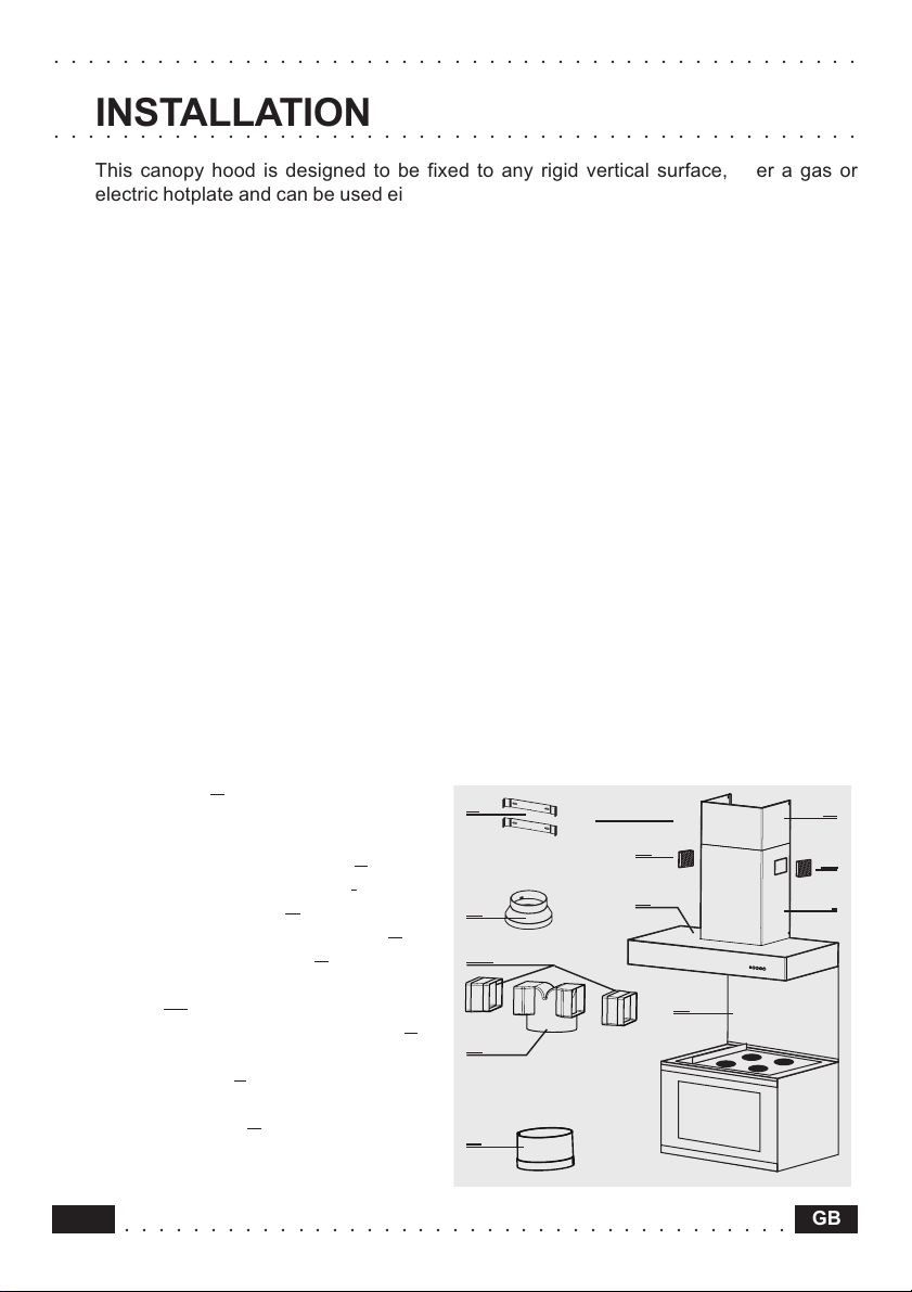
This canopy hood is designed to be fixed to any rigid vertical surface, over a gas or
electric hotplate and can be used either in the extraction mode (ducted to the outside) or
in the recirculation mode (internal recycling).
Safety warnings
• Before commencing the installation, consideration should be given to the difficulties
to be found during installation and to the bulky weight of the hood. The installation
work must be undertaken by a qualified and competent person in conformity to the
rules concerning the evacuation of contaminated air. The manufacturer disclaims all
liability for any damage or injury caused as a result of not following the instructions
for installation contained in the following text.
• When used in the extraction mode the cooker hood ducting must not be connected to
a flue which is used for exhausting fumes from appliances supplied with energy other
than electric such as a central heating flue or water heating flue.
• When istalled, the hood must be positioned at least 65 cm above a cooking appliance.
• Never do flambé cooking under this cooker hood.
• Never leave frying pans unattended during use as overheated fats and oils may catch
fire.
• If the room where the cooker hood is to be used contains a fuel burning appliance
such as a central heating boiler then this must be of the room sealed or balanced flue
type. If other types of flue or appliance are fitted ensure that there is an adequate
supply of air into the room. When the cooker hood is used in conjunction with other
appliances supplied with energy other than electric, the negative pressure in the room
must not exceed 0,04 mbar to prevent fumes being drawn back into the room by the
cooker hood.
Components
The hood comprises the following (fig.1):
• No.1 canopy
lighting and ventilator unit
• No.1 telescopic chimney, comprising:
No.1 upper chimney element
No.1 lower chimney element
• No.2 directional grills
• No.1 reduction flange Ø 150-120
• No.1 recirculation spigot
• No.2 additional side recirculation
spigots
• No.1 additional recirculation spigot
• No.1 bag containing:
No.2 brackets
screws, rawl plugs and documents.
• No.1 splashback B (optional)
C complete with controls,
G
P1
2 to fix the chimney,
R
2
S
I
A
A
P1
P
Fig. 1
G
C
B
R
P
S
G
I
14
○○○○○○○○○○○○○○○○○○○○○○○○○○○○○○○○○○○○○○○
GB
○○○○○○○○○○○○○○○○○○○○○○○○○○○○○○○○○○○○○○○○○○○○○○○
232
260
11
2
260
11
20
X
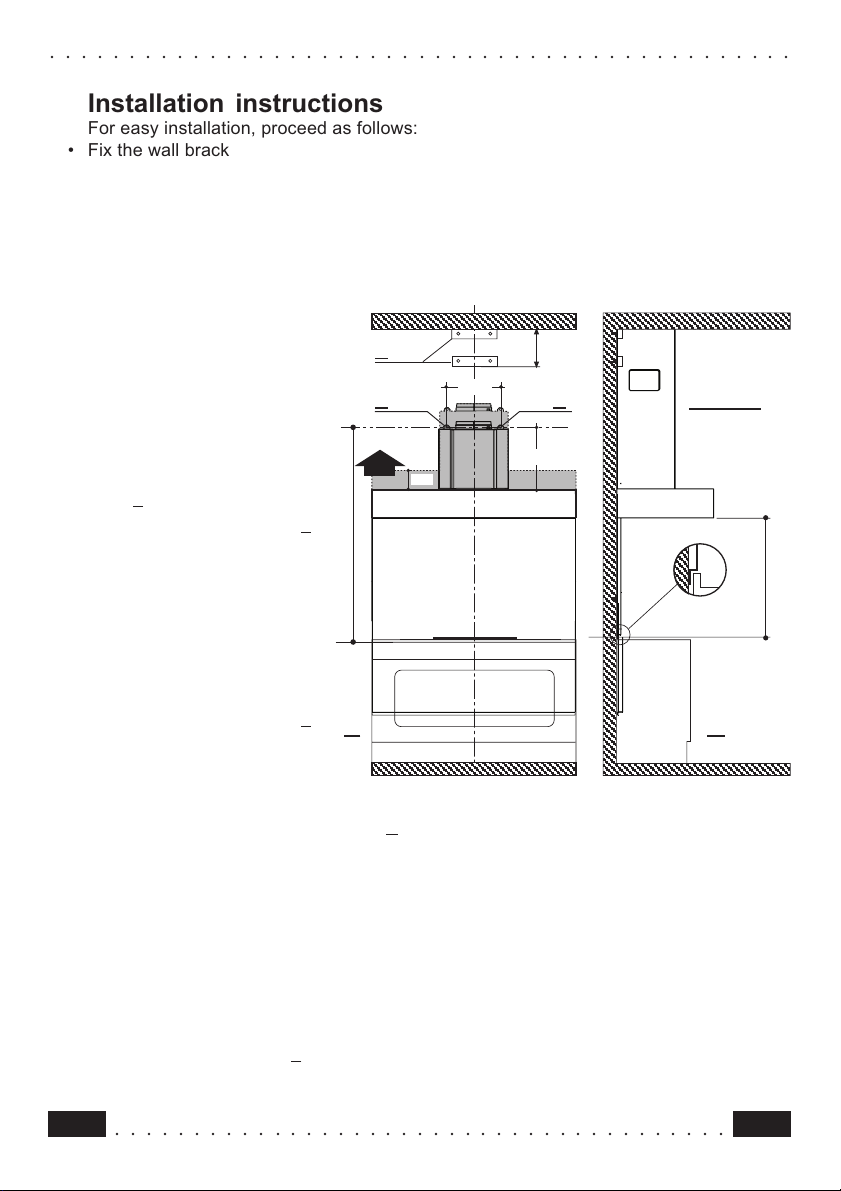
H min 650
d = 1030 min
Installation instructions
For easy installation, proceed as follows:
• Fix the wall brackets and Splashback
• Fix the canopy
• Connect the hood to the mains power supply and make sure that it works properly
• Set the hood for ducting or recirculation
• Fix the telescopic chimney
Fitting the wall brackets and Splashback
Please refer to (fig.2a-b):
• Draw a vertical line on the
wall, from the centre of the
cooking appliance up to the
ceiling, using a marking pen.
This is to ensure the correct
vertical alignment of the
various parts.
• Fixing the wall brackets
2:
item
• Place one of the brackets
2
against the wall
approximately 1 or 2 mm
from the ceiling or from the
top limit, aligning its centre
(slot) with the vertical line.
• Mark the centres of two
keyholes in the bracket on
the wall.
• Rest the other bracket 2
against the wall, aligning it
with the vertical line, at a
distance X measured as
shown in fig. 2 equal to the
height of the upper chimney element S supplied with the hood. The position X may vary,
a b
according to the various sizes of upper chimney element available.
• Mark the centres of the keyholes in the bracket on the wall.
• Drilling fixing holes item 1:
• Mark a point on the vertical line at a distance from the cooking appliances of:
d =1030 min (distance without splashback).
d =height of splashback + 380 mm (distance with splashback).The distance H is the
minimum height in mm from the cooking appliances to the bottom edge of the front panel
of the hood.
• At the point marked, draw a horizontal line parallel to the cooking appliances.
• Drill two holes in the wall
1 using an 8 mm drill bit (fig.2a ), and insert the rawl plugs and
screws into the holes 1 (4.2 x 44.4 screws). Fix the screws, leaving a space of 5-6 mm
required to hook up the canopy. Small adjustments can be made using the hood adjustment
○○○○○○○○○○○○○○○○○○○○○○○○○○○○○○○○○○○○○○○
Fig. 2
15GB
 Loading...