

Zanotti FZ214, FZ218, FZ221, FZ213, FZ219 Installation Manual
...
1
FZ213 - FZ214
FZ218 - FZ219 - FZ221
FZ228 - FZ229
LIBRETTO DI INSTALLAZIONE
INSTALLATION MANUAL
MANUEL D’INSTALLATION
MONTAGEANLEITUNG
LIBRO DE INSTALACIÓN
I
GB
F
D
E

44
CONTENTS
1. Safety recommendations
1.1 Warranty
1.2 Maintenance
1.3 Safety information
2
.
Table of warning and attention plates
3. Models available
3.1 Main technical features
4. Installation instructions
4.1. Display description
4.2. Instructions for battery connection to feeder
5. Unit dimensions and fitting
6. Cooling circuit and connections details
7. Controller description
7.1 Display descriptions
7.2 Set point setting and changing
7.3 Programming parameters
8. Operations
8.1 Road operation
8.2 Stand by operation
8.3 Rating operation
8.4 Defrosting
8.5 Alarms and sigallings
9. Wiring Diagram
10. How to order spare parts
11. How to dispose of the packing
12 . How to dispose of the unit
13. Wiring Diagram

45
Thank you for choosing Uniblock. Please read these instructions carefully. They provide details and advice
on the correct method of installing, using and maintaining this unit, in order to obtain maximum reliability,
efficiency and long life.
1. Safety recommendations
When installing and using the unit please follow the recommendations listed here below.
• Installation shall be carried out in strict compliance with the diagrams and instructions supplied by the
manufacturer.
• Damages due to improper connections are excluded.
• The electric system available where the unit is installed shall meet the relevant standards in force.
• Maintenance shall be effected by trained personnel or by the manufacturer according to the provisions
supplied by EN378.
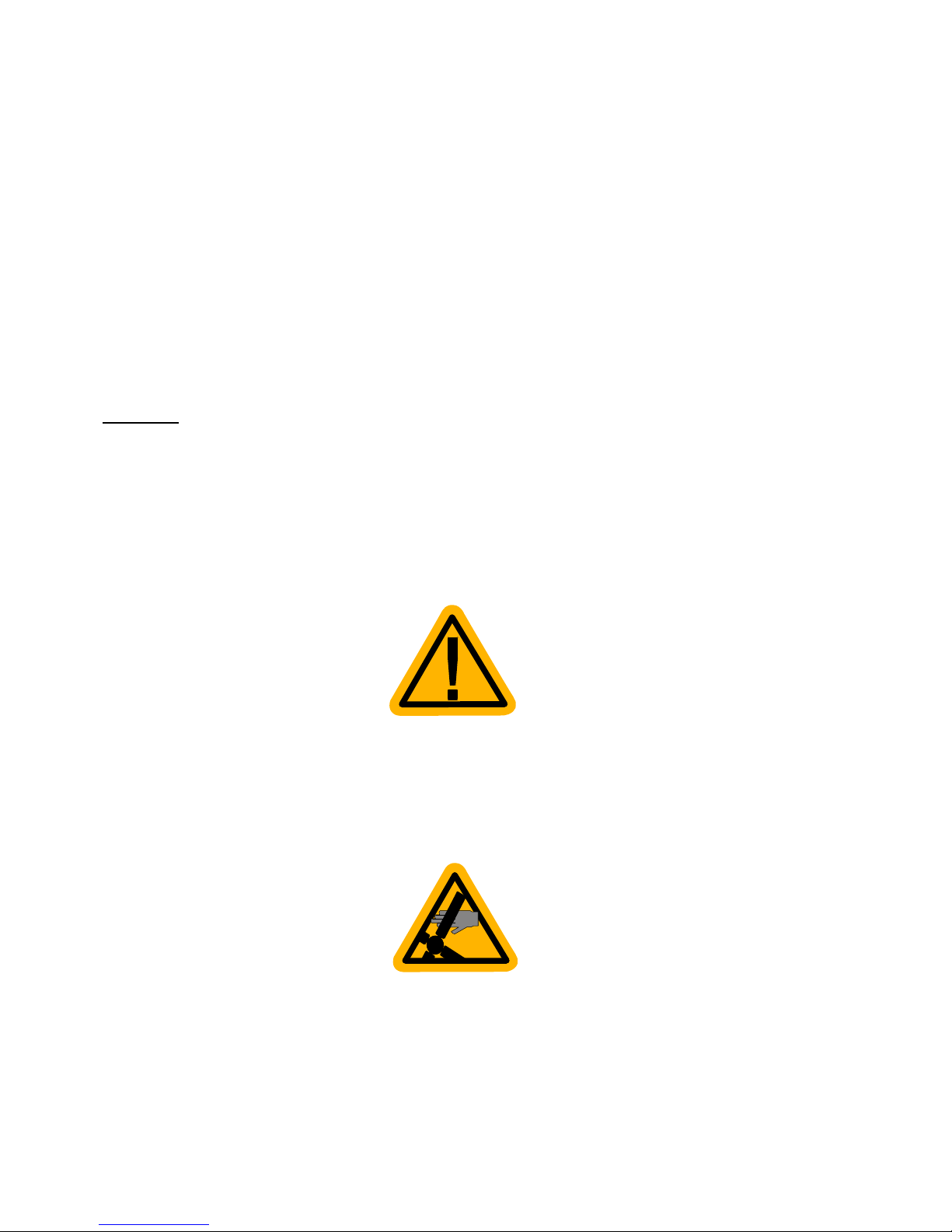
WARNING
Use safety gloves to protect your hands from possible cuts.
The user is strongly recommended to contact the manufacturer before attempting any intervention on the unit and
any use not corresponding to the manufacturer’s indications (in particular as for the field of application) and to
enquire about the possible dangers and contra-indications connected with an improper use of the machine.
• The unit shall be used following these instructions and sticking to the destination of use indicated by the
supplier. Any incorrect use can result in damages to the unit and represents a serious danger for people’s
health.
ATTENTION
The unit is not suitable for working in explosive environments.
Therefore the use of the unit in an explosion-dangerous atmosphere is absolutely
forbidden.
ATTENTION
The unit is not suitable for working in salty environments. In such a case protect
condenser and evaporator with appropriate means.
When maintenance involves operations on the refrigerating circuit, empty the system and let it reach the
atmospheric pressure.
WARNING
Do not discharge the refrigerant in the atmosphere. It must be recovered by specialized
technicians using suitable equipment.
• Quantity and quality of the refrigerant to be charged are indicated on the data plate.
• Do not use refrigerants of different kind (especially inflammable fluids, for example hydrocarbons) or air.
• Do not modify or alter the refrigerating circuit or its components (for example: welding on compressor
body)
• The final user shall protect the system from external fire dangers.
• The unit has been designed to ensure a constant temperature control during transport. The cold storage
room must be well insulated, provided with airtight door and optimal ventilation.
If the temperature of the product loaded is too high, the unit will not be able to cool it down.

46
For safe use of the unit, we suggest:
ATTENTION
• Do not use water or steam when cleaning as the electrical components may be damaged.
• Keep condenser and evaporator clean.
• Stand-by operation in enclosed places: ensure good ventilation to the condenser.
• Check that all screws are properly fixed and suitable to the purpose.
• When making holes in the unit or in the vehicle chassis, take care not to pierce the refrigerating pipings,
the electrical wiring or any other vehicle component.
• Never close the compressor discharge valve when the unit is working.
• When working on the unit, use only flexible pipes of gauges in good conditions and avoid touching belts,
pulley or fan.
WARNING
• Cleaning and maintenance are to be carried out with the unit switched OFF.
• After a running period, condenser and H/P discharge pipes are very hot; let them cool down before
carrying out any operation.
• Handle fans, belts and pulleys carefully, with the unit OFF: prevent them from unexpected starting.
• When working near the coils (condenser and evaporator), pay attention not to cut oneself with the edges
of the fins.
• When the unit is working, avoid putting hands near fans and belts.
• Refrigerant fluid handling has to be carried out taking all necessary precautions.
• Near a heating source refrigerant fluid produces an unpleasant smelling gas, irritating for the respiratory
system.
• Never heat with fire a cooling cylinder containing refrigerant fluid.
• For any kind of manipulation on the unit, take all possible precautions
• Refrigerant in liquid state evaporates in contact with the atmosphere and freezes everything it touches.
• First aid in case of freezing:
a) Cover the frozen part.
b) Immediately warm the frozen part by dipping into cold water.
c) If water is not available or impossible to use, gently wrap up the frozen part in a clean cloth.
d) If some refrigerant fluid sprinkles on the eyes, immediately rinse with clean water; as a precaution
consult a doctor.
e) call a doctor
• Refrigerant oil.
Synthetic types.
Avoid prolonged or repeated contact with skin.
Wash hands thoroughly after handling.
The unit starts automatically; keep away from moving components (belts, pulleys, fans).
47
1.1 Warranty
It is possible that certain options do not appear on the warranty, in this case contact our assistance
service. The chiller structure must be evaluated by the manufacturer in order to determine its capacity to support
the additional loads imposed by unit installation. These indications do not constitute an approval or a warranty on
the part of ZANOTTI S.p.A. regarding the integrity of the chiller. It may happen that some of the adaptable
elements described in the installation procedure do not correspond. If this should occur, contact our service office.
In order to improve the quality of our products, ZANOTTI S.p.A. reserves the right to modify them without
notice.
1.2 Maintenance
For the safety and upkeep of the refrigeration unit it is important that maintenance work is carried out following
the timing indicated by the manufacturer (see maintenance table).
Maintenance work, as well as repairs, must be carried out by ZANOTTI S.p.A. authorized repair shops.
1.3 Safety information
WARNING
• If using the refrigeration unit in a closed environment, use only the "MAINS" function (keep the vehicle motor
strictly turned off in order to avoid discharged gas poisoning).
• Ensure that there is a distance of at least 60 cm between the condenser and the ceiling, and adequate
external air circulation.
• Cleaning operations on the refrigeration unit are carried out with the system turned off and after waiting for
this to cool.
• To clean, use a cloth dampened with detergent.
• Do not use jets of water or steam under pressure as this could damage the system electrical parts.
MOVING PARTS
• As a rule, do not carry out maintenance work while the refrigeration system is in motion, and take all
precautions to avoid unwanted start-ups.
• · During maintenance or repair operations, pay attention to moving parts such as fans, belts and pulleys.
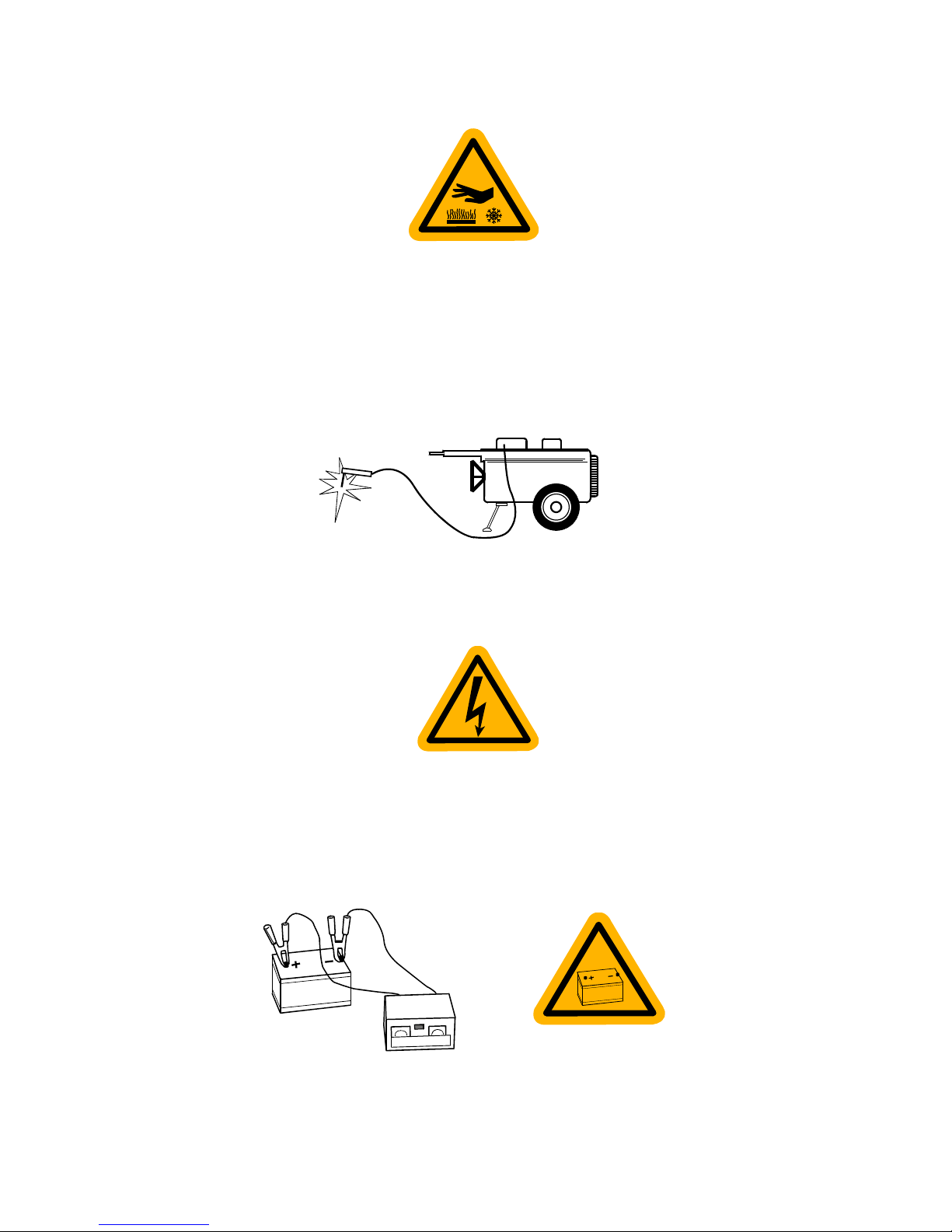
HOT SURFACES
• Do not use the refrigeration unit with fairing or panels open or dismantled.
• Do not obstruct condensation airflow in any way.
• At the end of each operation period, the compressor, the condenser and the high pressure piping will be very
hot. Avoid therefore any form of direct contact with these components during checking or repair stages until
they have cooled down.
• Check regularly that dust, detritus or foreign bodies do not block the air circulation around the radiator core of
the condenser and evaporator.
48
• If necessary, clean the parts in question.
• Do not let children operate the refrigeration system.
ELECTRIC SHOCKS
• Before opening the electric control box door, make sure that the power is turned off.
• Before carrying out any soldering work on the refrigeration system, disconnect the vehicle battery.
• Before carrying out soldering on the bodywork, ensure that the unit and vehicle batteries are disconnected, as
are the charge and three-phase alternators.
• Ensure that the electrical feed system has a ground connection device.
• Electrical systems in a residence or workshop must be connected to the refrigeration unit professionally by
expert staff.
BATTERY MAINTENANCE
• Check the electrolyte level of the vehicle battery regularly. If necessary, add distilled water.
• If the battery is run-down, recharge it and, if it is dead, check that the power is adequate for the use required
of it.
• Never start up your unit or vehicle with the help of a fast loader, so as not to risk damaging the electronic
system of the unit or vehicle.
49
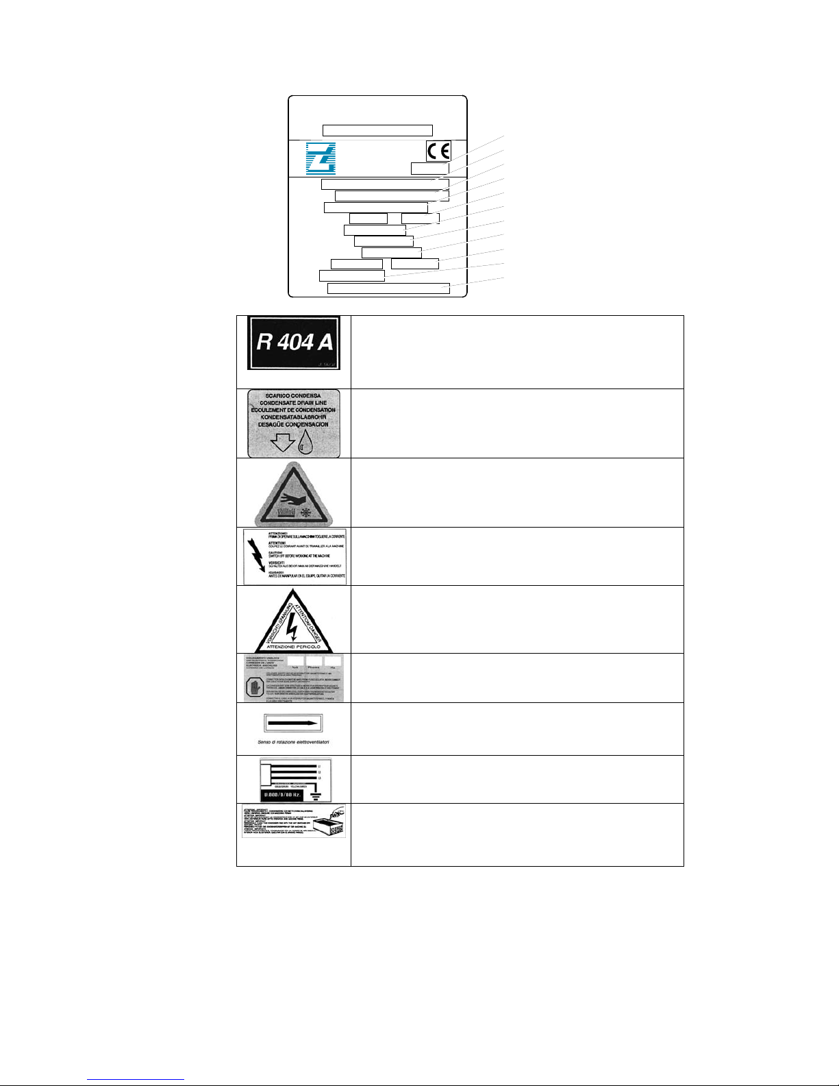
2. Table of warning and attention plates
Modello
Model
Matricola
Serial Number
Tensione
Voltage
Assorbimento Marcia
Run Absorption
Refrigerante
Refrigerant
Massa
Mass
V/Ph/Hz
AKw
Kg
Kg
Via Martin L. King, nr. 30
46020 PEGOGNAGA
(Mantova) - Italy
ZANOTTI
S.p.A.
Modello
Model
Potenza nom.compressore
Nominal Horsepower
A
A
Assorbimento Max
Max Absorption
Assorbimento di spunto
Starting Absorption
Kw
Schema nr.
Diagram nr.
Refrigerant
Condensate drain line
Attention: hot or cold parts
Attention: switch off before operating on the unit.
Attention: danger of electrocution
Connect this cable to a circuit breaker, never to
the main line directly.
Direction of rotation
Colours of supply cable wires
Attention – important : clean the condenser
periodically by blowing air from the inside
outwards.
Stop the unit before cleaning.
The F10 series models have been designed to be fitted onto vehicles suitable for the distribution of easily
perishable foodstuffs. They are split-type refrigerating units with automatic compressor.
FZ is suitable for product storage up to 0 °C, while F10M and FZ114 are suitable for product storage both in
negative and positive temperature.
1) Year of manufacture
2) ZANOTTI unit code
3) Serial number
4) Voltage
5) Run Absorption
6) Max Absorption
7) Starting Absorption
8) Compressor’s nominal power
9) Refrigerant : Type; Quantity
10) Mass of the unit
11) Electric diagram number

50
3. Models available
FZ 213-214-218-219-221-228-229
Cooling-cycle through 12V DC electric motor driven compressor, supplied by the vehicle battery or, alternatively,
by a remote current feeder connected to a 230V/1ph./50Hz mains supply (vehicle alternator must supply at least
90A).
The set temperature is maintained automatically.
3.1 Main technical fetures:
FZ213 Road Main
Road cooling capacity T amb. 30 °C T box 0 °C 2191 W 1324W
T amb. 30 °C T box -20 °C 1031 W 682W
Road compressor 145 cm³
Condenser fan helicoidal type 12 Vdc direct supply
Air volume 900 m³/h
Evaporator fan helicoidal type 12 Vdc direct supply
Air volume 660 m³/h
Main compressor 22 cm³
Electric motor (road) supply 230V/1 ~ /50Hz
FZ214 Road Main
Road cooling capacity T amb. 30 °C T box 0 °C 2627 W 1704W
T amb. 30 °C T box -20 °C 1377 W 716W
Road compressor 146 cm³
Condenser fan helicoidal type 12 Vdc direct supply
Air volume 850 m³/h
Evaporator fan helicoidal type 12 Vdc direct supply
Air volume 630 m³/h
Main compressor 87 cm³
Electric motor (road) supply 230/1 ~ /50Hz o 400/3N ~ /50 Hz
FZ218 Road Main
Road cooling capacity T amb. 30 °C T box 0 °C 1780 W 1560W
T amb. 30 °C T box –20 °C 940 W 830W
Road compressor 87 cm³
Condenser fan helicoidal type 12 Vdc direct supply
Air volume 850 m³/h
Evaporator fan helicoidal type 12 Vdc direct supply
Air volume 1400 m³/h
Main compressor 87 cm³
Electric motor (road) supply 230/1 ~ /50Hz o 400/3N ~ /50 Hz
FZ219 Road Main
Road cooling capacity T amb. 30 °C T box 0 °C 2830W 1661W
T amb. 30 °C T box –20 °C 1377W 878W
Road compressor 131 cm³
Condenser fan helicoidal type 12 Vdc direct supply
Air volume 850 m³/h
Evaporator fan helicoidal type 12 Vdc direct supply
Air volume 2300 m³/h
Main compressor 87 cm³
Electric motor (mains) supply 230/1 ~ /50Hz o 400/3N ~/50 Hz

51
FZ221 Road Mains
Cooling capacity T amb. 30 °C T box 0 °C 2879 W 2023 W
T amb. 30 °C T box –20 °C 1692 W 842 W
Road compressor 146 cm3 displacement
Condenser fan helicoidal type 12 Vcc o 24 Vcc direct supply
air volume 2000 m3/h
evaporator fan helicoidal type 12 Vcc o 24 Vcc direct supply
air volume 1150 m3/h
mains compressor 87 cm3 displacement
mains electric motore 230V / 1~ /50Hz 6,1 A 2 HP 1,5 Kw
(road oper.) 400V / 3N~ /50Hz 3,5 A 2 HP 1,5 Kw
FZ228 Road Main
Road cooling capacity T amb. 30 °C T box 0 °C 3174 W 2352W
T amb. 30 °C T box –20 °C 1793 W 1169W
Road compressor 146 cm³
Condenser fan helicoidal type 12 Vdc direct supply
Air volume 2000 m³/h
Evaporator fan helicoidal type 12 Vdc direct supply
Air volume 1150 m³/h
Main compressor 87 cm³
Electric motor (mains) supply 230/1 ~ /50Hz o 400/3N ~/50 Hz
FZ229 Road Main
Road cooling capacity T amb. 30 °C T box 0 °C 3732W 2570W
T amb. 30 °C T box –20 °C 2085W 1171W
Road compressor 145 cm³
Condenser fan helicoidal type 12 Vdc direct supply
Air volume 1350 m³/h
Evaporator fan helicoidal type 12 Vdc direct supply
Air volume 1350 m³/h
Main compressor 92 cm³
Electric motor (mains) supply 230/1 ~ /50Hz o 400/3N ~/50 Hz
4. Fitting compressor mechanical Kit on the road
See instructions for use supplied with Kit
This fitting must be carried out first.
Road compressor
In order to carry out installation correctly, check the components, see list of accessories.
Then proceed, following the instructions below.
Components
- Condenser (complete with electric control box)
- Evaporator
- Control box
LIST OF ACCESSORIES:
• Installation Kit FZ213-214-218-221 Cod.1KNS002
• Installation Kit FZ219 Cod. 1KNS003
• Installation Kit FZ228-229 Cod.1KNS004
• Electrical mains connection Kit 213/214/218/219/228T/229 Cod.1KCR003
• Electrical mains connection Kit 214/218/219/228M/229 Cod.1KCR004
• Electrical mains connection Kit 213 Cod.1KCR014
• Electrical road connection Kit 213/218/219/228/229 Cod.1KCS002
• Oil separator Kit FZ Cod. 1KSP001
• Refrigerator connection Kit
52
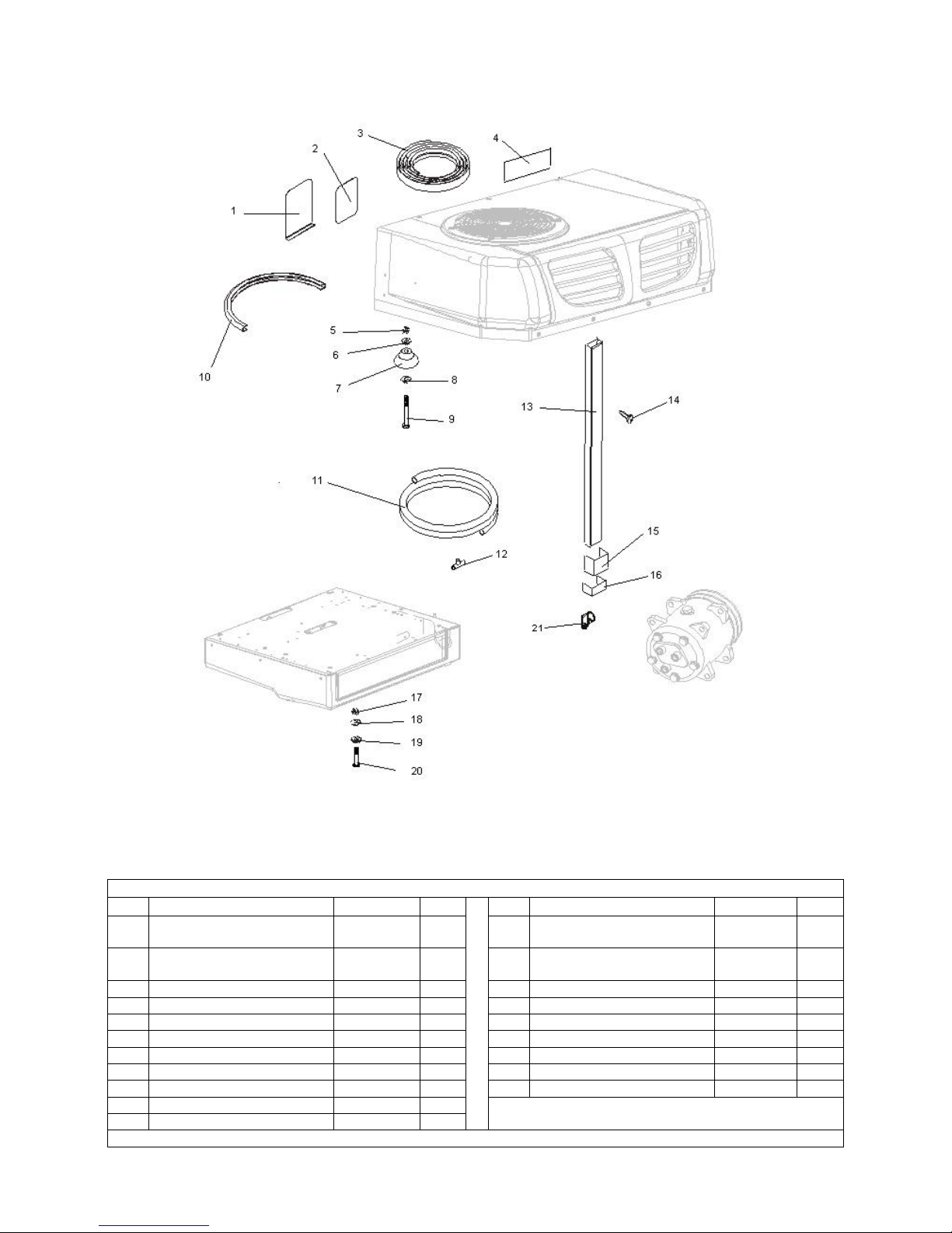
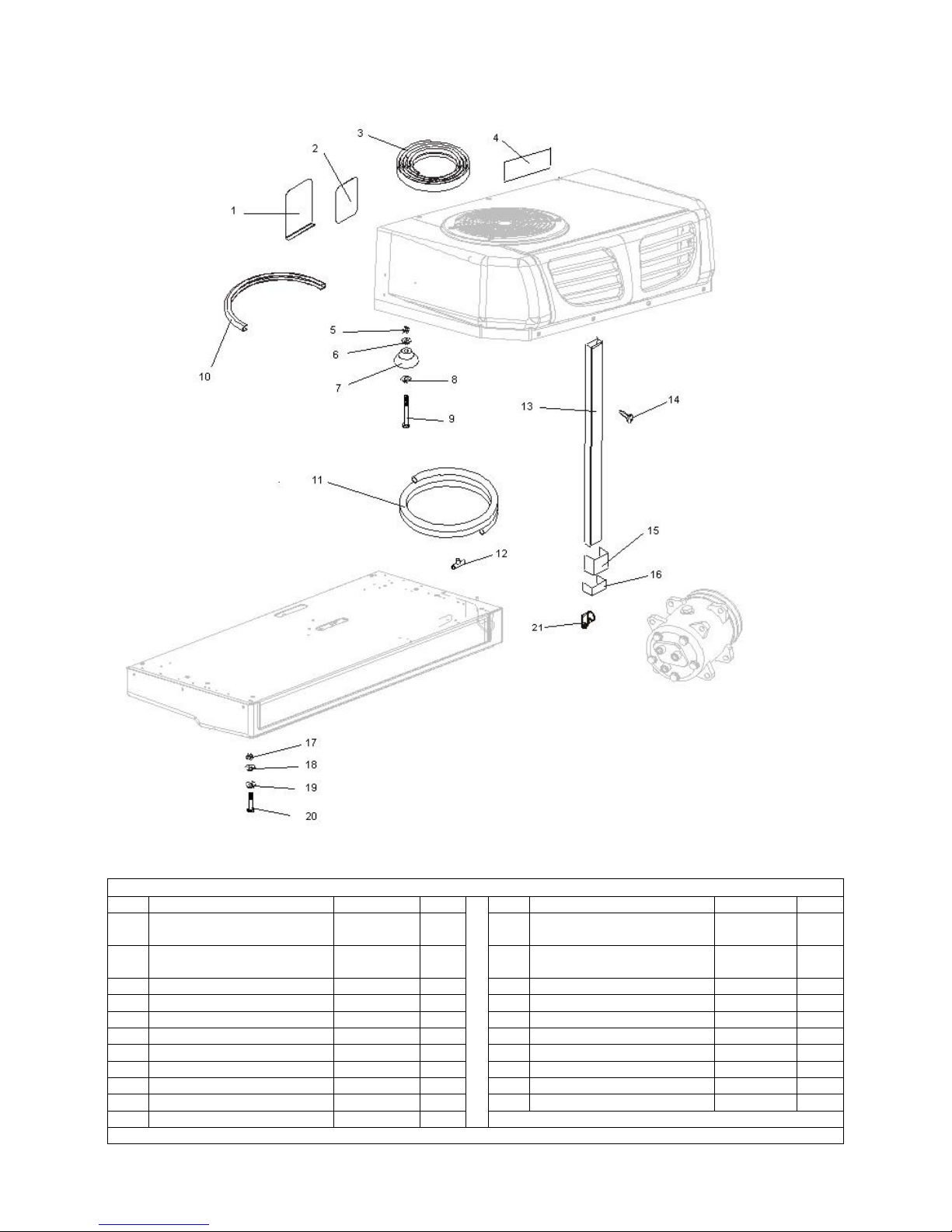
Kit SFZ213 / SFZ214
installation
Component List KNS
Descrizione Codice Q.tà Descrizione Codice Q.tà
1 Cable And Tube Pass. Ext.
Closing
3001242/A 1 13 Pipe Trough 3CNL015 2
2 Cable And Tube Pass. Int.
Closing
3001243/A 1 14 Self-Threading Screw 4,8X22 3VTE221 24
3 Gasket 3NST025 2.2 15 Internal Trough Bracket 3SFP012 4
4 Soldering Label 3ETA479 1 16 Trough Joint 3GNE002 1
5 Nut M 10 3DDO070 4 17 Nut M.8 3DDO077 4
6 Washer 10x20 3RND051 4 18 Washer 8x17 3RND045 4
7 Support Feet 3002042 4 19 Washer 8x32 3RND066 4
8 Washer 3RND065 4 20 Hexagonal Head Screw 3VTE327 4
9 Hexagonal Head Screw 3VTE318 4 21 Clamp With Screw 3FSC032 5
10 Gasket "U" 3GUR031 0.5
11 Spiral Pipe Ø 16 3TBG043 5
53
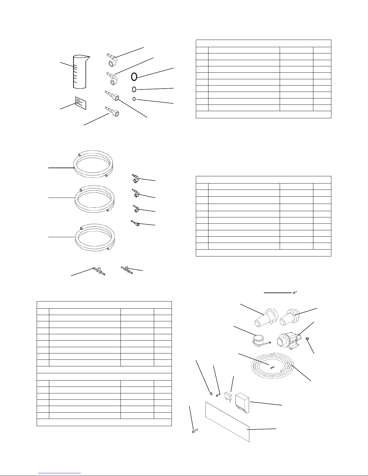
Compressor
Lot manuli
Electric mains connection
Component List KCM
Description
Code
Q.ty
1 Graduated Oil Container 3CNO001 1
2 Label 3ETA647 1
3 Union 7/8 s.10 3RCR099 1
4 Union 3/4 s.08 3RCR090 1
5 Union 7/8 s.10 3RCR071 1
6 Union 3/4 s.08 3RCR070 1
7 Gasket O-R 16 3GUR028 1
8 Gasket O-R 12 3GUR027 1
9 Gasket O-R 08 3GUR026 1
Component List LTM
Description
Codice
Q.tà
1 Frigostar Tube s.06 3TBG024
4
2 Frigostar Tube s.08 3TBG025
4,5
3 Frigostar Tube s.10 3TBG026
6,5
4 Joint s.08 3GNZ006 1
5 Joint s.10 3GNZ007 1
6 Union 11/16 s.06 3RCR103 1
7 Union 11/16 s.06 3RCR102 1
8 Union 1’’ s.10 3RCR100 1
9 Union 13/16 s.08 3RCR101 1
Component List KCR
Description
Code
Q.ty
1 Self-Threading Screw 3VTE221 1
2 Fixed Plug 3PSA015 1
3 Cover 3COP004 1
4 Non-Attached Plug 3SPN024 1
5 Fixed Plug 3SPN023 1
6 Washer 3RND007 1
7 Cable 3 X 2,5 3CV5100 1
8 Faston 6,3 3FFP005 1
Component List KCS
9 Washer 3RND007 1
10 Screw 3,9x16 3VTE275 1
11 Fuse 40 A 3FSB173 1
12 Fuse Base 3BSF054 1
13 Battery Connect. Label Fz 3ETA494 1
14 Non ins. eye 6 3OCP011 1
1
2
3
8
7
4
5
6
9
1
2
3
8
7
6
5
4
9
10
2
6
4
5
7
3
9
8
1
10
11
12
13
14
54
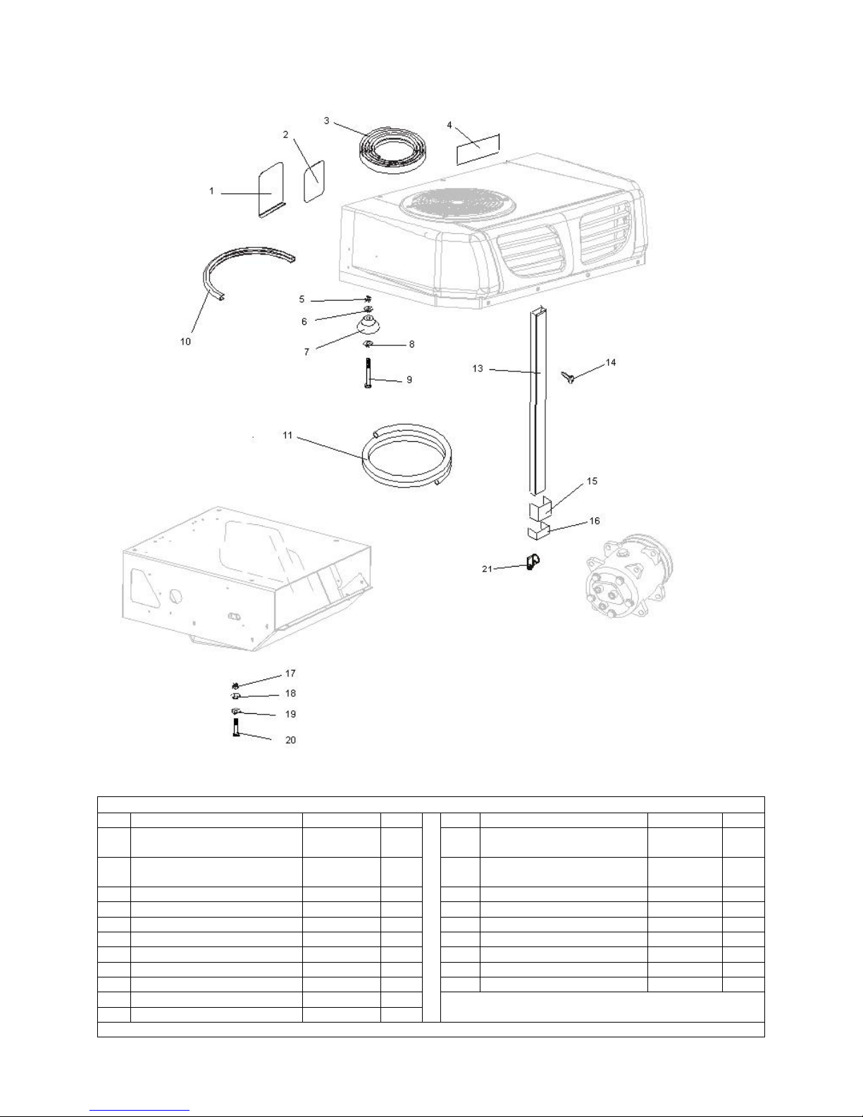
Kit SFZ218
installation
Component List KNS
Descrizione Codice Q.tà Descrizione Codice Q.tà
1 Cable And Tube Pass. Ext.
Closing
3001242/A 1 13 Pipe Trough 3CNL015 2
2 Cable And Tube Pass. Int.
Closing
3001243/A 1 14 Self-Threading Screw 4,8X22 3VTE221 24
3 Gasket 3NST025 2.2 15 Internal Trough Bracket 3SFP012 4
4 Soldering Label 3ETA479 1 16 Trough Joint 3GNE002 1
5 Nut M 10 3DDO070 4 17 Nut M.8 3DDO077 4
6 Washer 10x20 3RND051 4 18 Washer 8x17 3RND045 4
7 Support Feet 3002042 4 19 Washer 8x32 3RND066 4
8 Washer 3RND065 4 20 Hexagonal Head Screw 3VTE327 4
9 Hexagonal Head Screw 3VTE318 4 21 Clamp With Screw 3FSC032 5
10 Gasket "U" 3GUR031 0.5
11 Spiral Pipe Ø 16 3TBG043 5
55
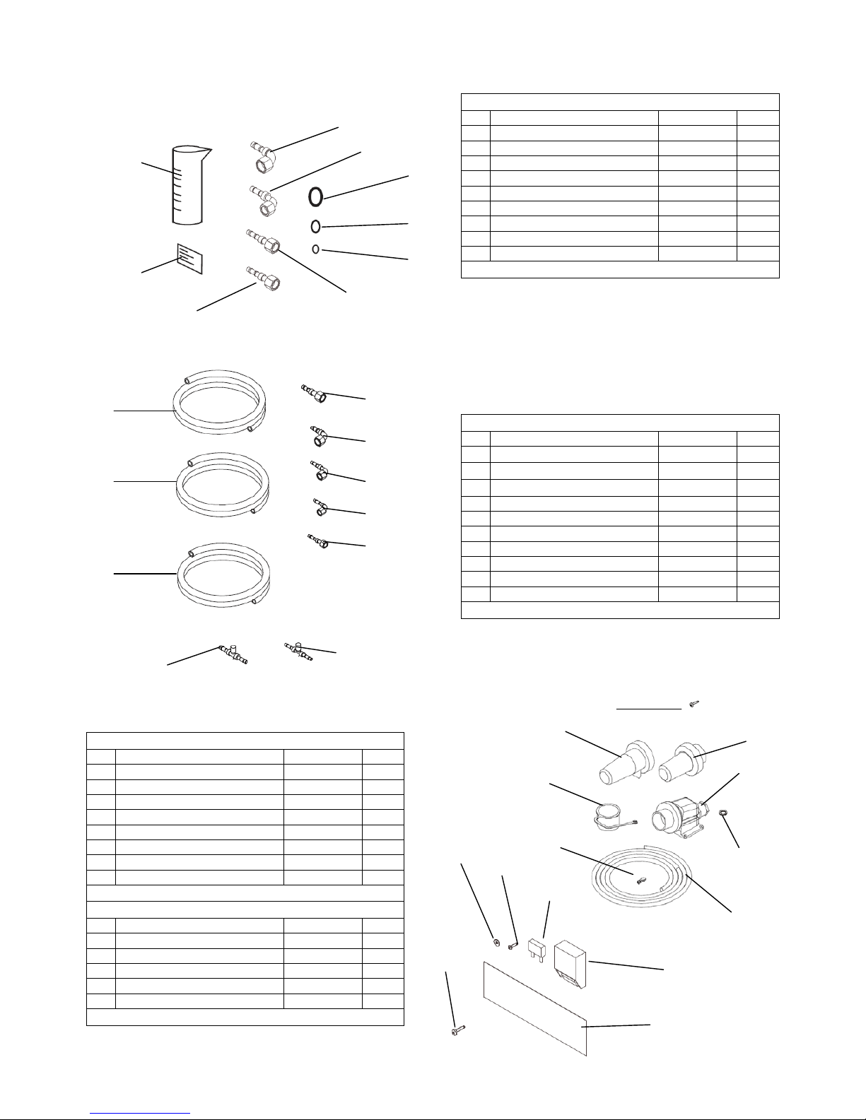
Compressor
Lot manuli
Electric mains connection
Component List KCM
Description
Codice
Q.tà
1 Graduated Oil Container 3CNO001 1
2 Label 3ETA647 1
3 Union 7/8 s.10 3RCR099 1
4 Union 3/4 s.08 3RCR090 1
5 Union 7/8 s.10 3RCR071 1
6 Union 3/4 s.08 3RCR070 1
7 Gasket O-R 16 3GUR028 1
8 Gasket O-R 12 3GUR027 1
9 Gasket O-R 08 3GUR026 1
Component List LTM
Description
Codice
Q.tà
1 Frigostar Tube s.06 3TBG024
4
2 Frigostar Tube s.08 3TBG025
4,5
3 Frigostar Tube s.10 3TBG026
6,5
4 Joint s.08 3GNZ006 1
5 Joint s.10 3GNZ007 1
6 Union 11/16 s.06 3RCR103 1
7 Union 11/16 s.06 3RCR102 1
8 Union 1’’ s.10 3RCR100 1
9 Union 13/16 s.08 3RCR101 1
10 Union 1’’ s.10 3RCR105 1
Component List KCR
Description
Codice
Q.tà
1 Self-Threading Screw 3VTE221 1
2 Fixed Plug 3PSA015 1
3 Cover 3COP004 1
4 Non-Attached Plug 3SPN024 1
5 Fixed Plug 3SPN023 1
6 Washer 3RND007 1
7 Cable 3 X 2,5 3CV5100 1
8 Faston 6,3 3FFP005 1
Component List KCS
9 Washer 3RND007 1
10 Screw 3,9x16 3VTE275 1
11 Fuse 40 A 3FSB173 1
12 Fuse Base 3BSF054 1
13 Battery Connect. Label Fz 3ETA494 1
14 Non ins. eye 6 3OCP011 1
1
2
3
8
7
4
5
6
9
1
2
3
8
7
6
5
4
9
10
2
6
4
5
7
3
9
8
1
10
11
12
13
14
56
Kit SFZ219
installation
Component List KNS
Descrizione Codice Q.tà Descrizione Codice Q.tà
1 Cable And Tube Pass. Ext.
Closing
3001242/A 1 12 T-Union 3TEE007 1
2 Cable And Tube Pass. Int.
Closing
3001243/A 1 13 Pipe Trough 3CNL015 2
3 Gasket 3NST025 2.2 14 Self-Threading Screw 4,8X22 3VTE221 24
4 Soldering Label 3ETA479 1 15 Internal Trough Bracket 3SFP012 4
5 Nut M 10 3DDO070 4 16 Trough Joint 3GNE002 1
6 Washer 10x20 3RND051 4 17 Nut M.8 3DDO077 4
7 Support Feet 3002042 4 18 Washer 8x17 3RND045 4
8 Washer 3RND065 4 19 Washer 8x32 3RND066 4
9 Hexagonal Head Screw 3VTE318 4 20 Hexagonal Head Screw 3VTE327 4
10 Gasket "U" 3GUR031 0.5 21 Clamp With Screw 3FSC032 5
11 Spiral Pipe Ø 16 3TBG043 5
 Loading...