

USER MANUAL V1.0

CONTENTS
Product Profile ................................................................. 04
Introduction .................................................................... 04
Specifications ................................................................. 04
Overview ......................................................................... 07
Aircraft ............................................................................. 07
Charging .......................................................................... 07
Installing the Battery ...................................................... 08
Unfolding the Arms ........................................................ 08
Compass Calibration .................................................... 09
Installing the Propellers ................................................. 09
Placement Before Takeoff .............................................. 10
Powering ON/OFF ........................................................... 10
Binding ............................................................................. 11
Binding the Aircraft and ST16S ............................................... 11
Binding the Aircraft and ION L1 PRO ........................................ 11
Takeoff ............................................................................. 11
Option 1 ............................................................................. 11
Option 2 ............................................................................. 12
Flight Modes .................................................................... 12
Angle Mode ......................................................................... 12
Exp curve function in Angle mode .................................................... 12
Flight Control Sensitivity function .................................................... 13
Cruise control function in angle mode ............................................... 14
Sport Mode ......................................................................... 14
RTL Mode ............................................................................ 15
Manual Mode ........................................................................... 16
Smart Mode ............................................................................. 17
Drone Settings .......................................................................... 18
Task Mode ........................................................................... 20
-
CCC ............................................................................... 20
-
Follow Me ...................................................................... 21
-
Watch Me ....................................................................... 21
-
Journey ......................................................................... 21
-
POI ................................................................................ 22
-
Orbit .............................................................................. 22
Landing ............................................................................ 23
Remote Controller .......................................................... 24
ST16S Charging .............................................................. 24
Flight Control .................................................................. 24
Proportional Control Rate Slider ................................... 25
Remote Controller Setting ..................................................... 25
General Settings .................................................................. 26
Camera Control ............................................................... 28
Gimbal Camera Tilt Control ................................................... 28
Gimbal Camera Pan Control .................................................. 28
Gimbal Control Setting ......................................................... 28
02

IONL1 PRO Camera Instructions .................................... 31
Gallery Function ............................................................. 39
Appendix .......................................................................... 41
Upgrading the Firmware ................................................ 41
LED Status Indication ..................................................... 43
Disclaimer ........................................................................ 44
Collection and Processing of Data ................................ 45
Battery Warnings and Usage Guidelines ...................... 45
General Safety Precautions and Warnings ................... 46
Camera Usage Warnings ................................................ 47
FCC Statement ................................................................ 47
RF Exposure Warning ..................................................... 47
IC Radiation Exposure Statement for Canada .............. 48
NCC Warning Statement ................................................ 48
CE Warning Statement ................................................... 48
EU Compliance Statement ............................................. 48
03

Product Profile
Introduction
The TYPHOON H3 provides high-end image quality combined with the reliability and automated ight
modes every photo and videographer desires. The TYPHOON H3 hexacopter is equipped with a 1"
camera with 4K video resolution, a PX4-based ight controller, ight modes from Follow Me and
Point of Interest to Curve Cable Cam. Relevant core areas of the TYPHOON H3 have been completely
redesigned to provide more reliability and power for your everyday needs.
Specifications
Aircraft
Product Name
Model
Max Takeoff Weight
Dimensions
Diagonal Size (Propellers Excluded)
Propeller Size
Propeller Pitch
Max Ascent Speed
Max Descent Speed
Max Speed
Max Tilt Angle
Max Angular Speed
Max Service Ceiling Above Sea Level
APV System
TYPHOON H3
70.55oz (2000g)
21.9x19.1x12.0in (556x485x305mm)
20.4in (520mm) (Six Rotors)
9.8in (248mm)
5.7in (145mm)
8.9mph (4m/s)
5.6mph (2.5m/s)
Sport: 44.7mph (72km/h), Angle: 31.1mph (50km/s)
Sport mode: 35°, Angle: 35°
150°/s
16404ft (5000m) (Tested)
Max Flight Time
Operating Temperature Range
Satellite Positioning Systems
Operating Environment
Sensor
Flight Speed
Motor Type Permanent Magnet Brushless DC motor
Motor KV 730
Motor Max Watt 180W (Rated Power)
Motor Max Speed 7500rpm
Approx. 25min
32° to 104°F (0° to 40°C)
GPS
Regular Flight Condition, No Transparent Obstacles
Ultrasonic Sensor
8.9mph (4m/s)
04

ESC Power (max) 25A
ESC Voltage 12V~20V
Flight Battery
Type
Capacity
Voltage
Energy
Net Weight
Charger
Charging Time
Max Charging Current
Max Discharging Rate
LIPO 4S
5250mAh
15.2V
79.8Wh
20.5oz (580g)
SC4000-4H
Approx. 1.5h-2h
5A
50A
ST16S Ground Station
Product Name Personal Ground Station
Model
ST16S
Operating System
Number of Channels
Control Transmission Distance/Range
Video Link Frequency Band
Video Transmission Distance/
Range(Optimum Conditions)
LCD Screen Size
Built-in Battery Voltage/Capacity
Max Charge Current
Android™
16
Up to 1 mile (1.6Km) (Optimum condition)
5.8GHz WiFi
FCC Compliance: up to 1.2mile (2km)
CE Compliance: up to 1.2mile (2km)
7in
3.6V 8700mAh 31.32Wh Li-ion
1A
ION L1 PRO Gimbal Camera
Product Name 3-Axis Gimbal Camera
ION L1 PROModel
General
Dimensions
5.1x3.1x5.1in (129x80x130mm)
05

Weight
13.2oz (375g)
Operating Temperature
Storage Temperature
SD Card Max/Min Capacity
32° to 104°F (0° to 40°C)
14° to 122°F (-10° to 50°C)
128GB
Gimbal
Stabilization
Angular Vibration Range
Mount
Max Angular Velocity
3-axis (tilt, roll, pan)
±0.02°
Detachable
Pitch: 30°/s, Yaw: 120°/s
Camera
Controllable Range Pitch: -110° to +30°
Sensor
Lens
Photo Resolutions
1 in CMOS, Effective Pixels: 20MP
FOV 91° F/2.8, 23mm Format Equivalent
3:2, 5472×3648 4:3, 4864×3648 16:9, 5472×3080
Video Resolutions
Photo Formats
Video Formats
Photography Modes
Exposure Mode
Exposure Compensation
H.264
4096×2160 (24/25/30/48/50/60fps)
3840×2160 (24/25/30/48/50/60fps)
2720×1530 (24/25/30/48/50/60fps)
1920×1080 (24/25/30/48/50/60/120fps)
1280x720 (24/25/30/48/50/60/120fps)
H.265
4096×2160 (24/25/30fps)
3840×2160 (24/25/30fps)
2720×1530 (24/25/30/48/50/60fps)
1920×1080 (24/25/30/48/50/60/120fps)
1280x720 (24/25/30/48/50/60/120fps)
JPEG, DNG, JPEG+DNG
MP4
Single, Burst (3/5/7), Interval (2s, 3s, 5s, 7s, 10s, 15s, 20s, 30s,
60s), AEB(±0.3, ±0.7), Panorama(Horizon,Sphere)
Auto Exposure, Manual Exposure,ISO Priority,
Shutter Priority
±3.0
ISO Range
Electronic Shutter Speed
White Balance
Metering Mode
100 – 6400
4 – 1/8000s
Auto,Lock,Daylight,Cloudy,Shade, Incandescent,
Sunrise,Custom(2000-12000K)
Spot Metering, Center Metering, Average Metering
06
Overview
01
02
03
01
02
03
04
01
02
03
04
05
06
07
08
23
24
09
12
13
14
15
16
17
18
10
19
11
20
21
22
25
26
27
TYPHOON H3
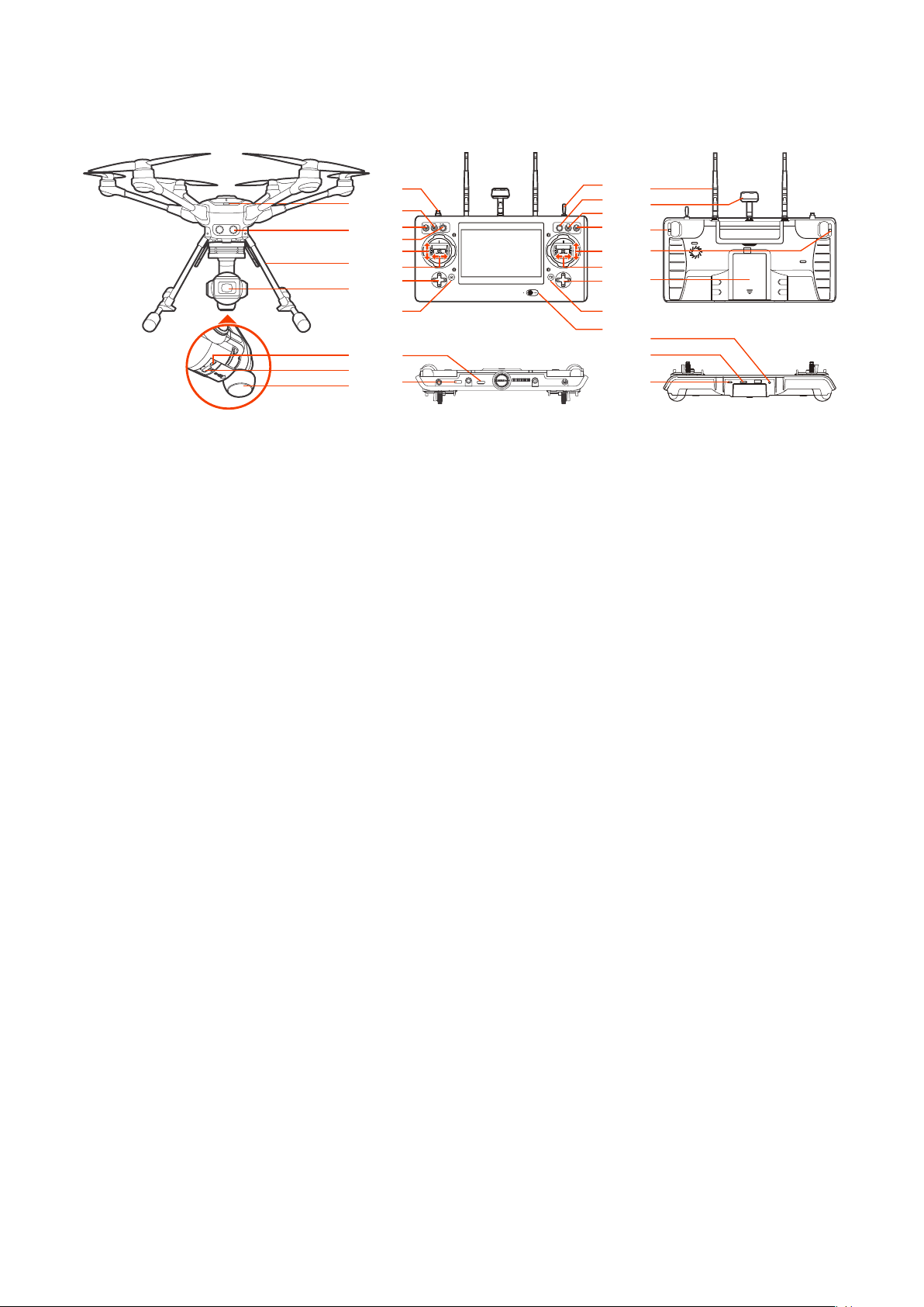
01 Power Switch
02 Sonar
03 Retractable Landing Gear
ST16S
01 Start/Stop Motor Button
02 Gimbal Pan Mode Switch
(Follow Mode/Follow Pan
Controllable Mode/Global Mode)
03 Gimbal Tilt Mode Switch
(Angle Mode/Velocity Mode)
04 Gimbal Pan Control Knob
05 Throttle/Altitude Control (Mode 2)
Elevator/Pitch Control (Mode 1)
06 Rudder/Yaw Control
(Mode 2 and Mode 1)
07 Left Trim(UP & Down EV value trim/
Left & Right digital Zoom )
08 Take Still Photo Button
09 Landing Gear Switch
10 Custom Setting Button
11 Obstacle Avoidance Switch
ION L1 PRO
01 Camera Lens
02 USB Port
03 Micro SD Card Slot
04 5GHz Antenna
12 Flight Mode Selection Switch
13 Elevator/Pitch Control (Mode2)/
Throttle/Altitude Control (Mode 1)
14 Aileron/Roll Control
(Mode 2 and Mode 1)
15 Right Trim (Cruise Speed Trim)
16 Start/Stop Video Recording Button
17 Power Switch
18 2.4GHz Antenna
19 5GHz Antenna
20 Proportional Control Rate Slider
21 Gimbal Tilt Control Slider
22 Battery
23 HDMI
24 USB Port
25 Headset Port
26 Micro SD Slot
27 Micro USB Port
Aircraft
Charging
Power the desktop charger from a 100-240V AC outlet using the AC adapter/power supply, or from a
12V-17.4V DC accessory socket/cigarette lighter receptacle in an automobile using the included adapter. Plug the aircraft battery into the charger port as illustrated.
07
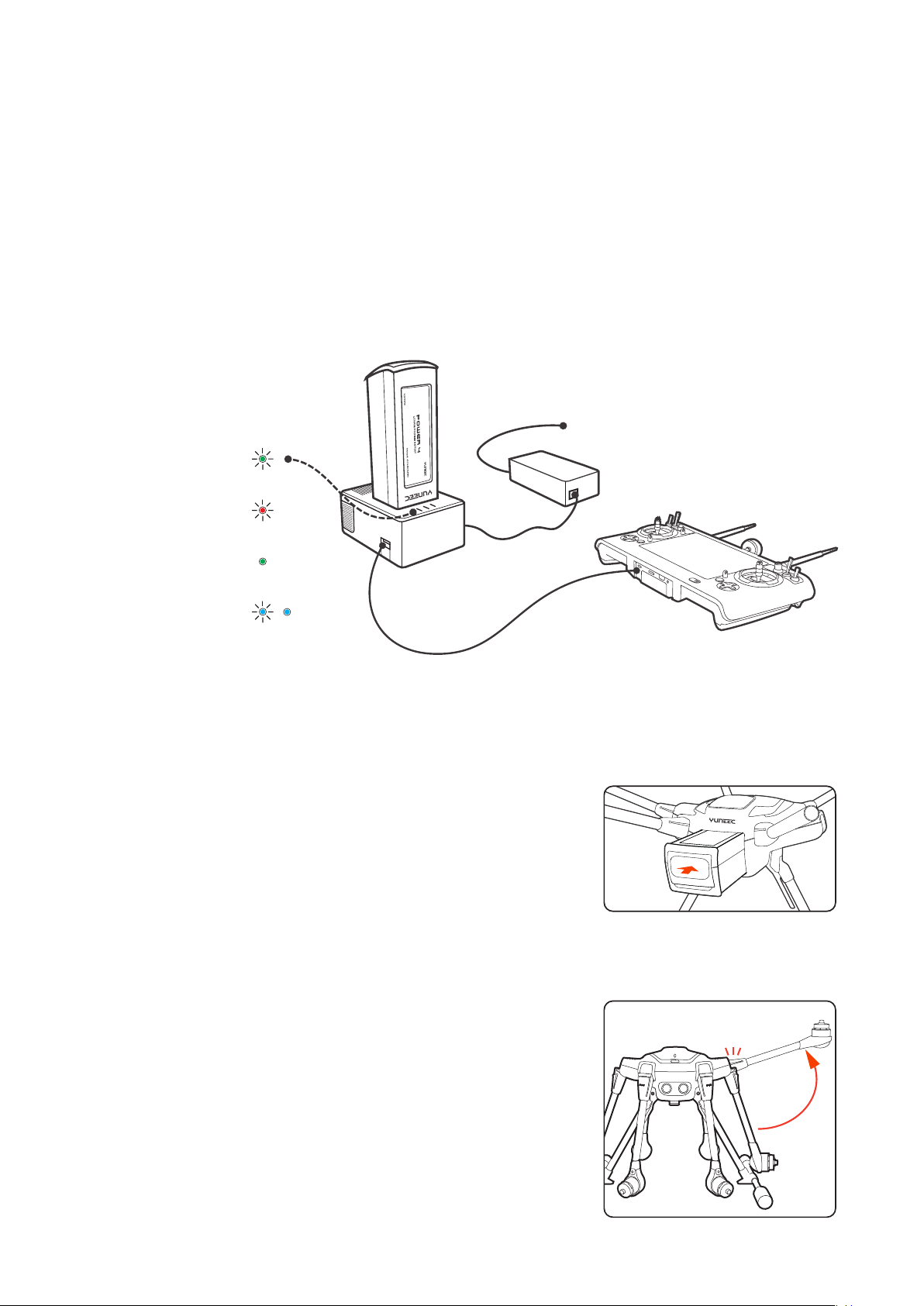
A green blinking LED indicates the charger is powered on and ready to charge, and a red blinking LED
push & click
unfold & click
indicates the battery is charging. It will take approximately 2.5 hours to charge a fully discharged (not
over-discharged) battery. A solid green LED indicates the battery is fully charged. Alternating blinking
and solid blue LED lights indicates Error.
Be certain to never completely drain a TYPHOON H3 battery. Batteries should be stored at 30-50%
charge, and never stored at full charge.
WARNING:
and/or serious injury as the mishandling of Li-ion/LiPo batteries can result in a re.
NOTICE:
and includes a storage function to either charge or discharge your battery to the safe storage percentage. To purchase it, please visit www.yuneec.com
All instructions and warnings must be followed exactly to prevent property damage
Yuneec offers a dual port quick charger (DY5, YUNDY3) that will charge your batteries faster,
power
Green Blinking:
Ready to charge
Red Blinking:
Charging
Solid Green:
Charge Completed
Blue Blinking / Solid:
Error
/
Installing the Battery
Push the battery into the battery compartment until hearing a
'click'.
Unfolding the Arms
Once the TYPHOON H3 has been removed from the storage/transport case, lock the arms in place. Gently lift the arms until a click
is heard.
To unlock the arms, press the PRESS button on the base of the
arms. On new systems, it may be necessary to release the arms
while lifting up on the bottom of the motor with one hand and
pressing the Press button with the other. Doing so relieves some
of the pressure on the locking system.
NOTICE: Do not depress the PRESS button on the arms while un-
folding and locking them into place; doing so may cause the
arms to not engage the locking system.
08
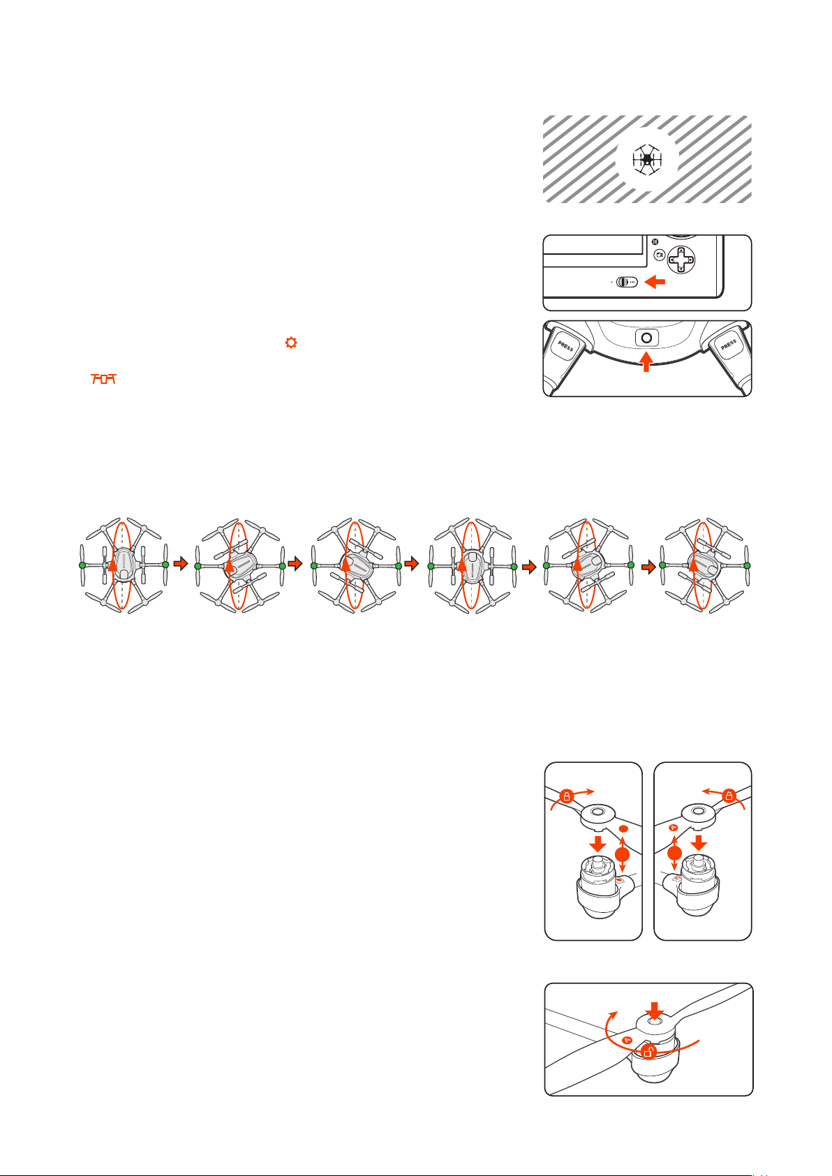
Compass Calibration
CAUTION: Do not calibrate the compass in parking garages, close to
buildings or near roads with a metal core. For optimum performance, only calibrate TYPHOON H3 in open spaces, far away from
power lines and other metal structures or concrete buildings.
NOTICE: Be sure to perform the compass calibration procedure at
least 11 feet away from the nearest cell phone or other electronic
devices to ensure proper calibration.
STEP 1: Power on the ST16S Ground Station rst and then the air-
craft, and make sure they are connected correctly. If they are not
connected correctly, the telemetry data will not display on the
screen.
STEP 2: Tap the System icon[ ] on the top right corner on the
ST16S, and then enter the aircraft setting interface by tapping
[ ], select the Compass Calibration.
STEP 3:
Lift the TYPHOON H3 airframe straight and level. When the LEDs on two motors start to blink green as
illustrated, turn it forward as shown by the red arrow until a tone is heard and the two LEDs turn off.
STEP 4:
Repeat this procedure for all six positions.
If the calibration has been successful, the LEDs under six motor arms will turn green ,also the ST-16S will
pop-up ” Compass calibration completed” on the screen.
IMPORTANT:
If the calibration has failed, all LED Status Indicators will blink red rapidly and the controller
will pop-up a "Compass calibration failed "on the screen, you must repeat the calibration process. If the calibration continues to fail, either the site of calibration is unsuitable or the compass is defective. Refer to
YUNEEC service center.
Installing the Propellers
Each arm of the TYPHOON H3 has a letter A or letter B labeled on it. “A”
arms have black center buttons; “B” arms have white center buttons.
Each propeller has an A or B label etched into the blade. “A” propellers
cannot be attached to “B” motors, nor can “B” propeller be mounted to
an “A” motor.
Match the A propellers with the A arms (black center button) and the B
propellers with the B arms (white center button). Place the prop on the
motor, lightly press down and while holding the motor and turn the prop
a quarter turn. A click will be heard and the center button will slightly pop
up. Hold the motor and test propeller security to assure a locked propeller.
B
B
B
A
Disassembling the propellers
Press and hold the center button into the mounting plate, and then rotate
the propeller in the direction the arrow points to.
IMPORTANT NOTICE:
Always check the props for damage and rough
edges. Damaged props may cause in ight vibrations causing unwanted
ight characteristics. Propellers should be replaced every 20 ight hours.
09
Placement before Takeoff
WARNING: Always operate the TYPHOON H3 in open areas (approximately 10000 square feet/930
square meters or more) that are free from people, vehicles, trees and other obstructions. Never y
near or above crowds, airports or buildings.
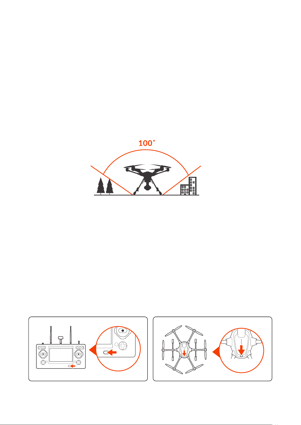
Never attempt to operate TYPHOON H3 nearby tall buildings/obstructions that do not offer a clear view
of the sky (a minimum clearance of 100°).
Be sure to place the TYPHOON H3 on a level and stable surface before powering ON the TYPHOON H3
Aircraft and the ST16S Ground Station.
IMPORTENT NOTICE: STEP BACK APPROXIMATELY 26 FEET (8 METERS)
BEHIND THE TYPHOON H3.
NOTICE: Pilots are recommended to take off the aircraft in Angle Mode. If the pilot takes off the aircraft
in Smart Mode, make sure to keep the air craft 32.8ft (10m) away from the pilot.
NOTICE: For the best performance, the 5.8GHz patch antenna should be pointed to the aircraft.
Powering ON/OFF
NOTICE: Please make sure all rmware is the latest version. Firmware and the user manual may be
downloaded from web site: www.yuneec.com. The quick start guide does not replace the user manual.
Turn on the ST16S, and then press the power button on TYPHOON H3. Release the button when the
aircraft emits a rising tone. Power on the ST16S before powering on the UAS.
NOTICE: If the Screen pops up a initialization failed on the screen. The aircraft needs to be powered on
again. To power off the aircraft, press and hold the power button until the aircraft emits a falling tune.
POWERING
ON ST16S
POWERING ON
TYPHOON H3
10
Binding
Binding the aircraft and ST16S
NOTICE: The aircraft and ST16S Ground Station are already bound out of factory. There is no need to
bind them. Pilot can follow the steps below if binding is needed.
STEP 1: Power on the TYPHOON H3. After initialization completes, the two LEDs on rear arms will blink
blue.
STEP 2: Lift the aircraft upside down until all LEDs blink yellow quickly, and then turn the aircraft back
on straight and level ground.
STEP 3: Switch on the ST16S Ground Station. Wait a few seconds for all systems to be boot up.
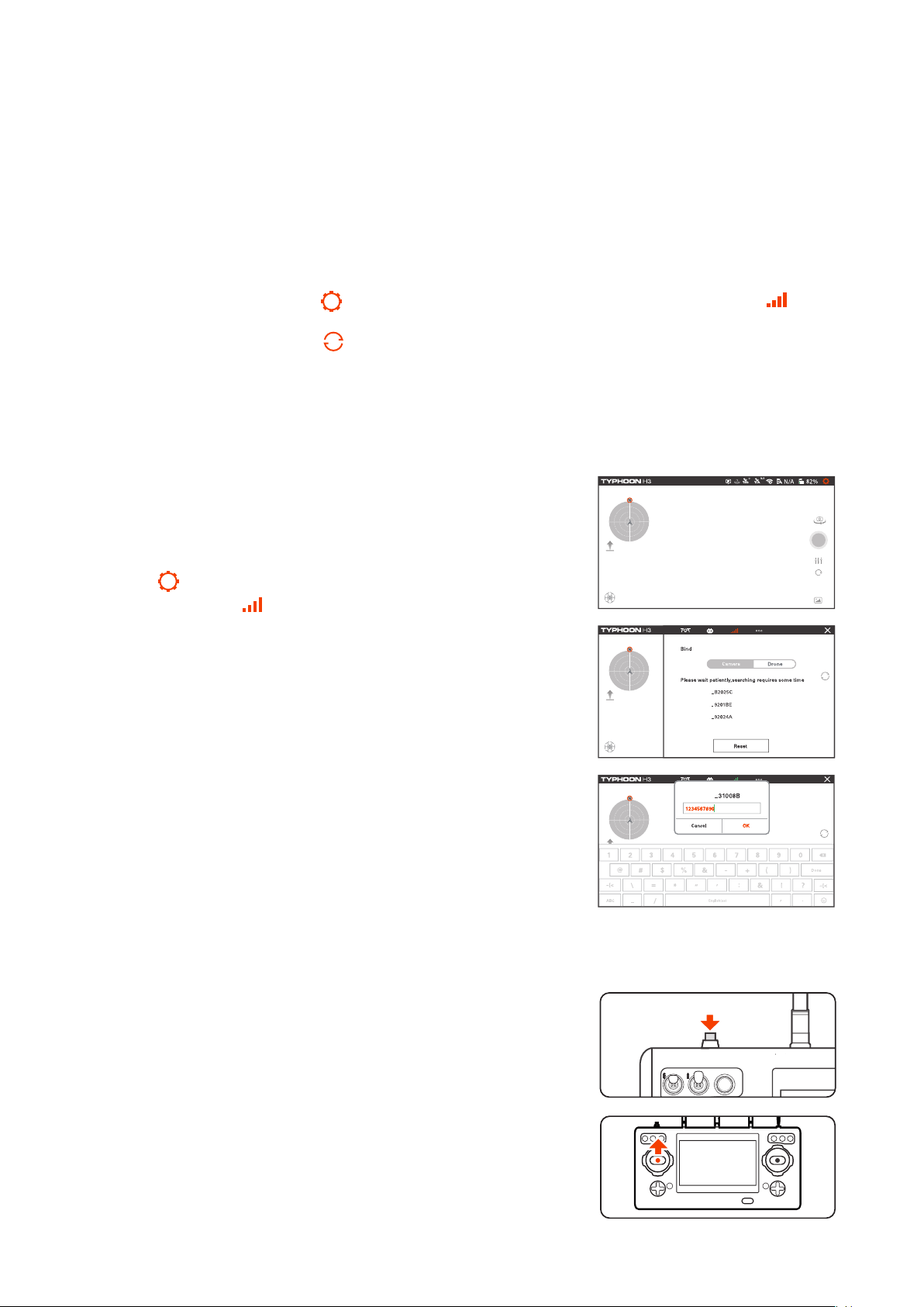
STEP 4: Tap the settings icon [ ] on the right top corner of the ST16S. Select the icon [ ] and
slid to the "Drone" selection.
STEP 5: Tap the refresh icon [ ],and then tap OK to unbind RC link. Select the corresponding
receiver listed in the column. Wait until a tip pops up to indicate the binding is completed.
Binding the aircraft and ION L1 PRO
Step 1.
Switch on the ST16S followed by the TYPHOON H3 aircraft.
Step 2.
Tap the[ ]on the top right corner on the main interface of
ST16S, then tap the[ ]on the switching interface.
Step 3.
Tap the serial number of the ION L1 PRO when the following
window pops up. (If multiple Yuneec UAS are used,check the ID
number on the side of each camera to assure correct camera selection/binding).
Step 4.
Using the password “1234567890”, authorize the camera and tap
"OK" to conrm.
NOTICE:
If the connection process is delayed, close the pop up
window and then repeat the above steps.
Takeoff
IONL1P
IONL1P
IONL1P
IONL1P
Option 1
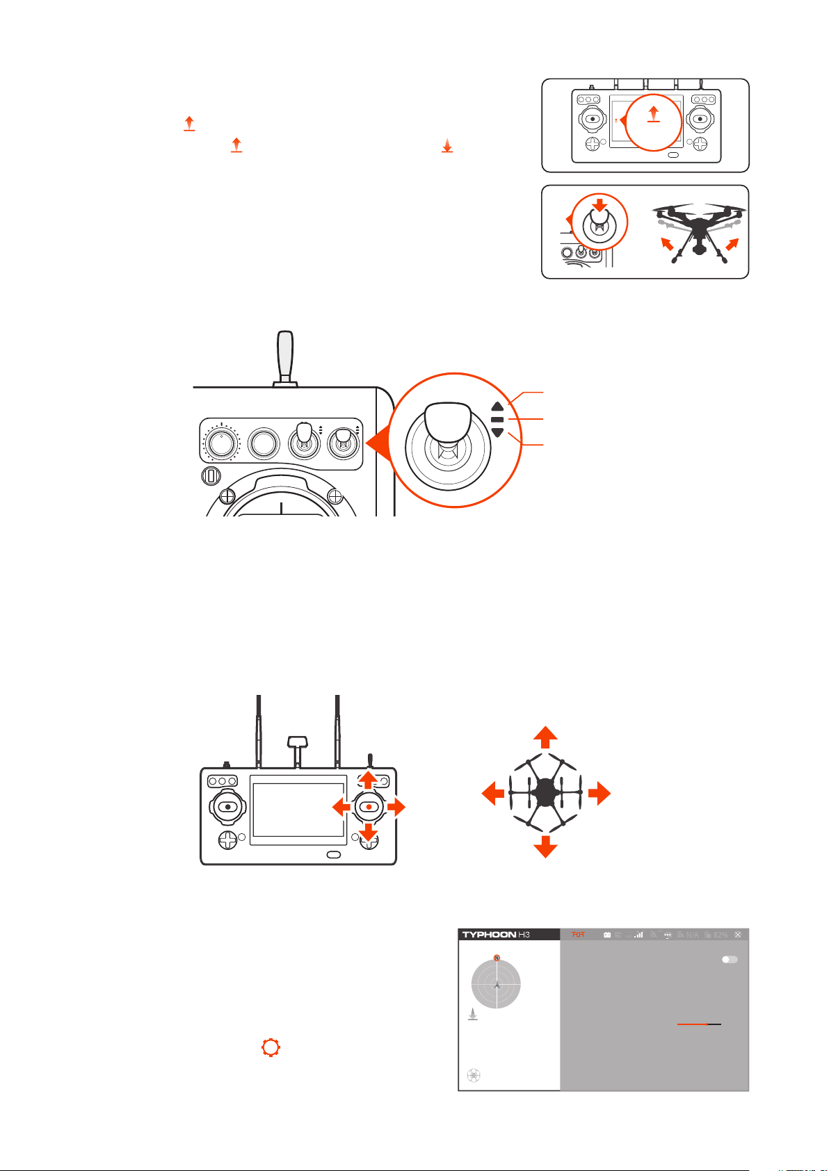
Press and hold the START/STOP button until the aircraft boot up.
Step back approximately 26 feet (8 meters) behind TYPHOON H3.
When there is suitable GPS signal for both the ST16S Ground Station and TYPHOON H3, slowly raise the left-hand stick to slightly
above the center position. The aircraft will take off and climb slowly
(or raise the stick further until it does). Allow the stick to return to the
center position when the aircraft reaches the desired altitude.
11
Option 2
Take Off
Press the icon ( ), then slide the sliding block, and the aircraft will
take off. Then the icon ( ) will turn Point-to-Land icon ( ).
Retracting the Landing Gear
Raise the landing gear control using the landing gear control switch
on the ST16S.
Flight Modes
SPORT MODE
ANGLE MODE
RTL MODE
Angle Mode
If the Flight Mode selection switch is in the center position, then the aircraft is in Angle Mode. In this
mode the aircraft moves in line with the joystick, in the direction in which the nose is pointed. So, if
you move the right stick to the left, the TYPHOON H3 will tilt to the left and thus move to the left. That
is assuming that the nose is pointing away from you. If the nose is pointing towards you, the aircraft
will move to the right from your point of view.
NOTICE: TYPHOON H3 will hold its position automatically when GPS is on (if there is sufcient GPS
signal) and it will retain the altitude level if the left stick is in the middle position.
Exp curve function in Angle mode
This function is used to adjust the Operational Curve
of joystick function (throttle, aileron, elevator and
rudder) in Angle ight mode, so as to achieve the
most user-friendly airplane control feel.
1.Click the settings button[ ]at the top right to nd
"Flight Control Settings" in the aircraft options and
open this menu.
12
Flight Manual Mode
Compass Calibration
Flight Control Settings
Cruise Speed 7m/s
Other Settings
>
>
10m/s2m/s
2.Interface introduction.
1)The curve on the left is the throttle Exp curve;
2)The middle curve is the direction Exp curve
3)The curve on the right is the Exp curve shared by
aileron and elevator
4)The parameters of the current curve are marked
in the rectangular lattice below each curve
5)Reset button
< Flight Control Settings
Angle Mode EXP
up
down
1.00
Flight Control Sensitivity
turn left
turn right
0.94
Reset
forward/right
back/left
0.91
3.Setting introduction
Power on the aircraft and remote control before set-
Angle Mode EXP
up
turn left
Reset
forward/right
ting. Wait until the camera, aircraft and remote control are connected before using this function normally
1)For sliding setting, the three curves can be set by
sliding directly with ngers. Press and hold the curve
to be adjusted with ngers, then drag it up and down
until the curve reaches the desired shape, and then
release your hand to complete the setting.
, 6
/
*
=
(2+)
down
1.00
1-
7 8
*
turn right
0.94
3.
54
9
0
#
DONE
back/left
0.91
2)Parameter setting: parameters under the coordinate system can be directly set for three curves to
achieve the setting purpose. Click the parameters under the curve coordinate system to be set, and
then the screen will pop up the keyboard. The user can input parameters as required to accurately
change the Exp curve. After setting, click Done to save the current setting.
NOTICE: the parameter settings range from 0 to 1.
3)Click Reset in the upper right corner and click Yes
in the pop-up box to restore all three curves to the
factory settings.
4)After setting, green √ will pop up on the screen,
indicating that the setting is successful and effective,
Reset params of the angle mode EXPO
< Flight Control Settings
Angle Mode EXP
up
Will Reset Exp Chart
No Yes
down
0.07
Flight Control Sensitivity
turn left
turn right
0.00
Reset
forward/right
back/left
0.82
otherwise the setting will not take effect, please reset.
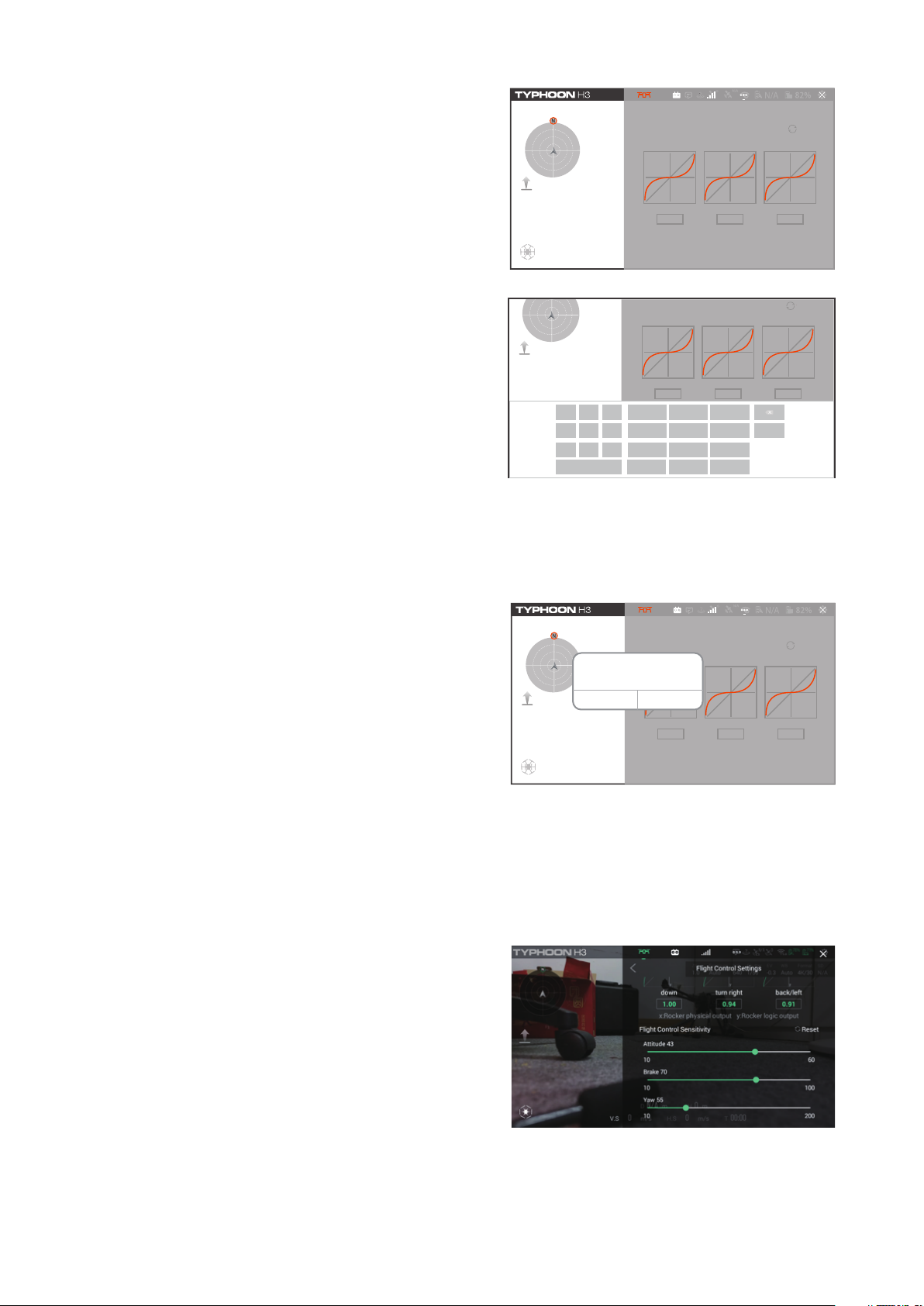
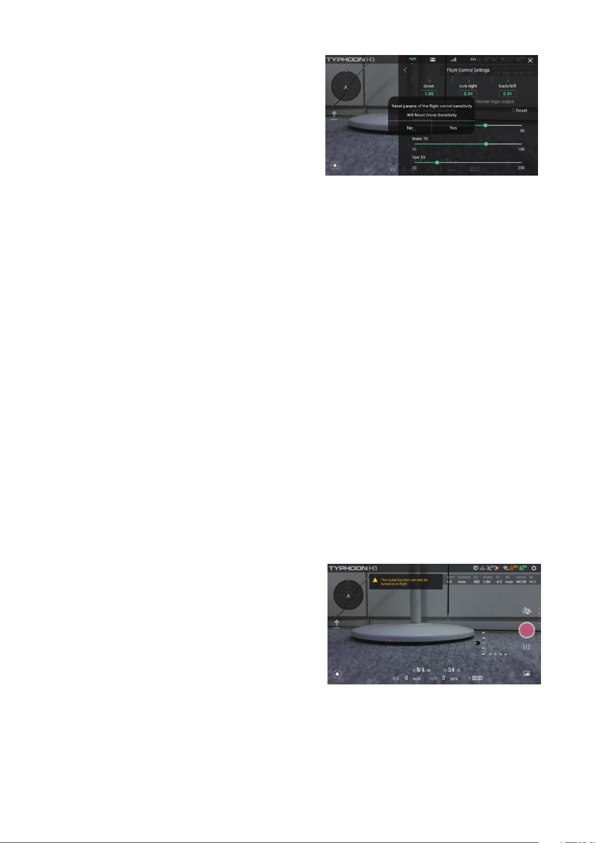
Flight Control Sensitivity function
This function can adjust the sensitivity of the control
to achieve the most user-friendly aircraft handling
feel
1.Click the settings button at the top right, nd "ight
control settings" in the aircraft options, open this
menu, and then slide down to nd the ight control
sensitivity function
2.Interface introduction
1)The top slider sets the slider for attitude sensitivity;
2)The middle slider sets the slider for brake sensitivity;
3)The bottom slider sets the slider for Yaw sensitivity.
4)Reset button.
3.Setting introduction
Before setting, power on the aircraft and remote controller, and wait for the camera, aircraft and
remote controller to be connected before use of this function.
13
1) If we slide the attitude sensitivity slider to the right,
the attitude control of the aircraft will become more
sensitive, and it will take shorter time for the aircraft
to reach the desired attitude from hovering state; otherwise, if we slide to the left, the attitude control of
the aircraft will become more sluggish, and it will
take longer for the aircraft to reach the desired attitude from hovering state;
2) If you slide the brake sensitivity slider to the right, the aircraft's brake will become more sensitive. It
will take a shorter time for the aircraft to recover from the motion state to the hovering state, and the
stopping distance will also be shorter. If you slide the slider to the left, the aircraft's brake will become
more sluggish. It will take a longer time for the aircraft to recover from the motion state to the hovering state, and the stopping distance will also be longer;
3) When sliding the directional sensitivity slider to the right, the angular velocity of aircraft spin will be
increased under the same rudder input compared with that before sliding; otherwise, when sliding the
slider to the left, the angular velocity of aircraft spin will be decreased under the same rudder input
compared with that before sliding;
4) Click Reset in the upper right corner and click Yes in the pop-up box to restore all three sliders to the
factory settings;
5) After setting, green √ will pop up on the screen, indicating that the setting is successful and effective. Otherwise, the setting will not take effect. Please reset.
NOTICE:
This setting should only be set for experienced pilots and on their own responsibility.
Cruise control function in angle mode
This function is used to assign a xed speed to the
aircraft in angle mode, so that the aircraft can automatically run at a stable speed, so as to obtain
smooth and stable video.
1) Take off and hover after angle mode with GPS positioning;
2) Press the up key of the right trim, the aircraft will
move forward at a slow and constant speed, and
press again, the aircraft will move forward at a faster
speed until the maximum value of the trim is
reached;
3) Press the down key of the right trim, the aircraft
will move backward at a slow speed and constant
speed, and press again, the aircraft will y backward
at a faster speed until the maximum value of the trim
is reached;
14

4) Press the right button of the right trim, and the aircraft will move right at a slow speed and constant
speed. Press the right button again, and the aircraft will y to the right at a faster speed until the maximum value of the trim is reached;
5) Press the left key of the right trim, the aircraft will move left at a slow speed and constant speed,
and press again, the aircraft will y left at a faster speed until the maximum value of the trim is
reached.
NOTICE: when the aircraft is in constant speed cruise state, press the trim key in the opposite direction
to slow down the aircraft. Press in the opposite direction repeatedly or continuously to slow down the
aircraft to hover or even reverse direction constant speed cruise.
NOTICE: when the aircraft is in constant speed cruise state, it can exit from constant speed cruise
mode by moving pitch and aileron joysticks substantially or switching ight mode
As shown in the gure, after the aircraft enters the constant speed cruise mode, the screen will display
the trim display as shown in the gure below, indicating the trim amount.
RTL Mode
When the Flight Mode selection switch is in the bottom position, TYPHOON H3 will be in RTL (also
known as Return to Land) Mode.
In RTL Mode the GPS connectivity will y back TYPHOON H3 in a straight line in the direction of the
pilots’ current location, and automatically land within 13-26ft (4-8m) of the pilot. It can be helpful for
pilots that lose orientation during ight. Simply activate RTL Mode until TYPHOON H3 automatically
moves toward the home position, and once you've conrmed orientation switch back to Angle Mode.
If the TYPHOON H3 ever loses the link with the ST16S Ground Station it will automatically enter RTL
Mode.
NOTICE:
If the signal of remote control is lost, TYPHOON H will automatically return to home point
and hold its position (with a suitable GPS signal/lock) over the home position except for low battery.
Before switching to RTL Mode, press the Setting Calibration button on the right top corner of the
screen. Select Aircraft setting icon and set a height as the desired altitude, and then RTL Mode
can be activated. The ight path is as follows:
1.
When the ight height of the aircraft is lower than the desired altitude, it will climb to the desired
altitude vertically rst, then y back at the current height and descend vertically within 13-26ft (4-8m)
of the pilot until it lands automatically.
2.
When the ight height of the aircraft is higher than the desired altitude, it will y back at the current
height, and then descend vertically within 13-26ft (4-8m) of the pilot until it lands automatically.
15
 Loading...