

Page 1
V11172015
Page 2

INTRODUCTION
SPECIFICATIONS
GENERAL WARNINGS
SAFETY PRECAUTIONS
OVERVIEW
SD CARD INSTALLATION
LED STATUS INDICATION
AERIAL IMAGING SYSTEM
ATTACHING CGO4 GIMBAL CAMERA TO MULTI-COPTER
BINDING CGO4 GIMBAL CAMERA TO THE ST24 (SINGLE MODE)
CAMERA CONTROL ON MULTI-COPTER(SINGLE MODE)
BINDING CGO4 GIMBAL CAMERA TO THE ST24 (TEAM MODE)
BINDING H920 MULTI-COPTER TO THE ST12 (TEAM MODE)
CAMERA CONTROL ON MULTI-COPTER (TEAM MODE)
CGO4 INTERFACE(ST24)
PHOTO TAKING AND VIDEO RECORDING
CAMERA MODE INTRODUCTION
ADJUSTING THE WHITE BALANCE
SETTING THE LIGHT SENSITIVITY
COMPENSATING THE EXPOSURE
SPECIFYING THE APERTURE/ SHUTTER SPEED
MENU SETTING INTRODUCTION
GROUND IMAGING SYSTEM
APP DOWNLOADING
ATTACHING CGO4 GIMBAL CAMERA TO PROACTION
BINDING CGO4 GIMBAL CAMERA TO APP
GIMBAL CONTROL ON PROACTION
APP INTERFACE
PHOTO TAKING AND VIDEO RECORDING
CAMERA MODE INTRODUCTION
ADJUSTING THE WHITE BALANCE
COMPENSATING THE EXPOSURE
SETTING THE LIGHT SENSITIVITY
SPECIFYING THE APERTURE/ SHUTTER SPEED
ADJUSTING THE FOCAL LENGTH
CONTROL MENU INTRODUCTION
CAMERA-S
MENU SETTING INTRODUCTION
DISCLAIMER
FCC STATEMENT
01
01
02
03
03
04
04
05
05
06
07
07
08
09
09
10
11
11
11
11
12
15
15
15
15
18
18
19
20
20
20
20
21
21
21
21
24
25
TABLE OF CONTENTS
Page 3
INTRODUCTION
The TORNADO ProAction™ is a ground imaging system designed to extend your Panasonic® camera GH4 and SONY® α7 with real-time imaging transmission. The system includes
the ProAction™ ground handle and GB603 gimbal. The ProAction™ features pitch controller,
allowing for precise camera angle control. The GB603 gimbal, 3-Axis self-stabilizing
gimbal, enables you to capture smooth and fluent photographs and video footage.
The CGO4 is an independent high end professional all in one gimbal camera module,
specially developed for professional users who require ultra-high aerial imaging quality and resolution. The dream of an adjustable, all-function, remote-controlled, 4/3
inch sensor and aerial capturing system is now a reality.
CGO4 incorporates a true Panasonic GH4 camera with a 3x optical zoom lens and an
integrated 5.8GHz video link module all housed in purpose designed casing. It can be
installed on both the TORNADO H920 copter and the ProAction ground SteadyGrip
system. All the regular Panasonic GH4 camera settings can be freely and remotely
adjusted through Yuneec ST24 transmitter which totally transforms and reshapes the
boundaries of aerial imaging creation. Through the user friendly control app interface
in the ST24, the CGO4 becomes an incredible tool to realize the highest levels of
aerial photographic and video graphic imagery.
SPECIFICATIONS
PROACTION™
DIMENSIONS: 14.17x10.04x14.57in (360x255x370mm)
WEIGHT (without battery): 52.91oz (1.5kg)
BATTERY WEIGHT: 7.72oz (219g)
INCLUDED BATTERY: 4S/14.4V 0.3C 2600mAh 37.44 Wh Lithium-Ion Battery
RUNTIME: 2.5 Hours
WORKING VOLTAGE: 12.0~16.8V
WORKING CURRENT: 0.68~1.0A
COMPATIBLE DEVICE: GB603 / CGO4
CGO4
DIMENSION: 6.5 x 8.6 x 7.7 in (165 x 219 x 196 mm)
WEIGHT: 1200 g
GIMBAL AXES: 3
CONTROL ANGLE ACCURACY: ±0.01°
MAXIMUM CONTROL RANGE:
Pitch [-90° to 0° (for H920) /- 90° to 30° (for ProAction)] Yaw [360° limitless]
MECHANICAL RANGE: Pitch [-120° to 45°] Roll [ -40° to 40°] Yaw [360° limitless]
MAXIMUM CONTROL SPEED: Pitch: 30° /s Yaw: 30° /s
INPUT/OPERATING VOLTAGE: 24V
CURRENT CONSUMPTION/OPERATING CURRENT: 1A
STORAGE TEMPERATURE: 10°C - 30°C
WORKING TEMPERATURE: -5°C - 45°C
IMAGE SENSOR: 4/3 inch Live CMOS Sensor
EFFECTIVE PIXELS: 16Megapixels
MAX VIDEO RESOLUTION: 4K 30FPS, 100 Mbps
DIGITAL VIDEO DOWNLINK: Integrated
COMPATIBLE LENS: [ 3x Optical zoom 14-42mm (standard configuration)]
[OLYMPUS M.ZUIKO DIGITAL ED 12mm f2.0 ] [ OLYMPUS M.ZUIKO DIGITAL 45mm f1.8 ]
FOCUS MODE: AFS/MF
SHUTTER SPEED: 1/8000s to 60s
ISO RANGE: 100 to 25600
1
Page 4
GENERAL WARNINGS
IMPORTANT NOTE: All safety precautions and warnings, instructions, warranties and other
collateral information is subject to change at the sole discretion of Yuneec. For the most
up-to-date information please visit the corresponding product page at www.Yuneec.com or
contact the nearest Yuneec office or authorized distributor.
The following special language terms are used throughout the product literature to indicate
various levels of potential harm when operating this product:
NOTICE: Procedures, which if not properly followed, create a possibility of property damage
and/or little to no possibility of injury.
CAUTION: Procedures, which if not properly followed, create the probability of property
damage and/or a possibility of serious injury.
WARNING: Procedures, which if not properly followed, create the probability of property
damage, collateral damage and/or serious injury or create a high probability of superficial
injury.
WARNING: Read the ENTIRE instruction manual to become familiar with the features of the
product before operating. Failure to operate the product correctly can result in damage to
the product, property and/or cause serious injury.
WARNING: This is a sophisticated consumer product. It must be operated with caution and
common sense, and requires some basic mechanical ability. Failure to operate this product in
a safe and responsible manner could result in damage to the product, property and/or cause
serious injury. This product is not intended for use by children without direct adult supervision. Do not use with incompatible components or alter this product in any way outside of the
instructions provided by Yuneec. The instruction manual contains instructions for safety,
operation and maintenance. It is essential to read and follow all the instructions and warnings
prior to assembly, setup and/or use in order to operate the product correctly and avoid
damage or serious injury.
WARNING: Failure to use this product in the intended manner as described in instruction
manual can result in damage to the product, property and/or cause serious injury. This
product is not a toy!
WARNING: As the user of this product you are solely and wholly responsible for operating it
in a manner that does not endanger yourself and others or result in damage to the product
or the property of others.
2
Page 5
SAFETY PRECAUTIONS
PROACTION
Do not touch or move the ProAction within about 12s until the initialization is completed.
Do not operate the ProAction in the rain!
Do not expose the ProAction to fire sources!
The ProAction can't be operated after the second level low voltage battery warning!
CGO4
Do not expose the CGO4 gimbal camera to water.
Do not expose the CGO4 gimbal camera to rain, moisture, dripping or splashing.
Do not expose the lens of the CGO4 gimbal camera to excessive light sources.
Do not operate the CGO4 gimbal camera in environments with extremely high or low
temperatures and high humidity.
Do not press the lens with excessive force.
Do not leave the camera with the lens facing the sun as rays of light from the sun may cause
it to malfunction. Also, be careful when placing the camera outside or near a window.
Do not try to repair the CGO4 gimbal camera by yourself.
Do not attempt to operate CGO4 gimbal camera in areas with potential magnetic and/or
radio interference including areas nearby broadcast towers, power transmission stations, high
voltage power lines, etc.
Do not operate the Gimbal in the rain!
Do not expose the Gimbal to fire sources!
Do not touch or move the Gimbal until the initialization process has been completed.
In need of repair, send the CGO4 gimbal camera back to the service center.
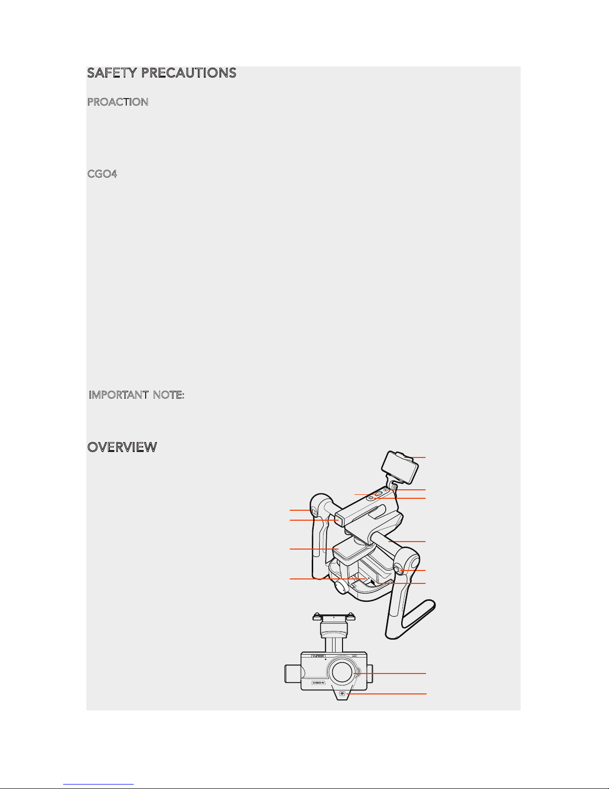
OVERVIEW
01
02
03
10
04
05
06
07
08
09
11
12
13
01 Power/Mode Selection Switch
02 Battery Indicator
03 CGO4 Gimbal
04 Phone Holder
05 Control Status Indicator
06 Pitch Control Wheel
07 Function Switch Button
08 ProAction™ Hand Holder
09 Gimbal Control Stick
10 CGO4 Camera LED Indicator
11 T Card Upgrade Port
12 CGO4 Camera Lens
13 CGO4 5.8G Antenna
IMPORTANT NOTE:
Remove the fixed foam pad from the CGO4 gimbal camera before
proceeding. Reinstore the fixed foam pad to the CGO4 gimbal camera after using.
3
Page 6
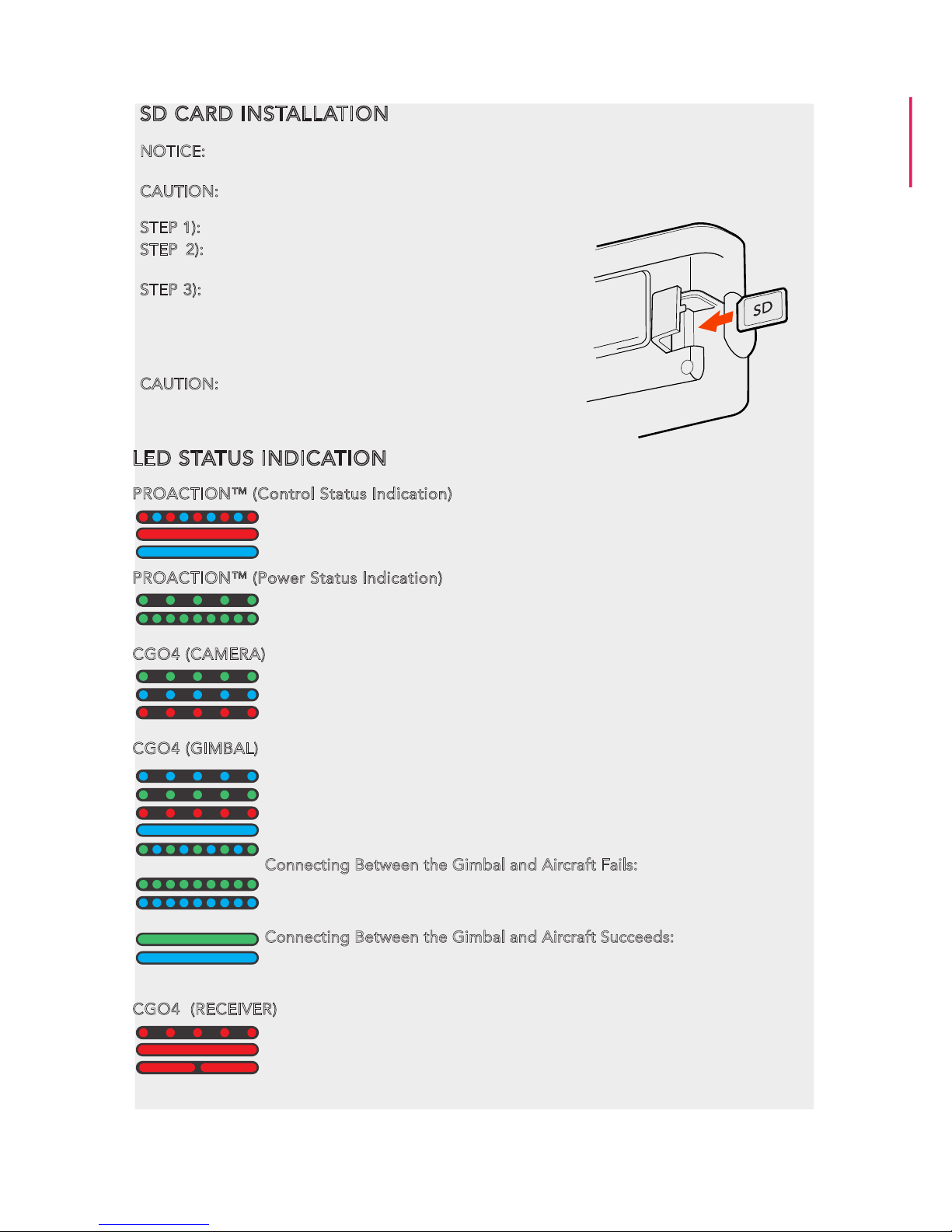
SD CARD INSTALLATION
NOTICE: Before photo-taking, SD card should be fully inserted into the camera. (The SD card
is not included in the package.)
CAUTION: Power off the camera before inserting or removing the card.
STEP 1): Remove the rubber bumpers.
STEP 2): Slide the memory card into the card slot in
accordance with the direction indicated by the sticker.
STEP 3): When fully inserted, the card clicks into place.
To remove the card, place your fingernail against the
edge of the memory card and lightly press it further into
the camera. The card springs out far enough to be
removed.
CAUTION: Keep the Memory Card out of the reach of
children to prevent swallowing.
LED STATUS INDICATION
PROACTION™ (Control Status Indication)
Boot Self-inspection: LED blinking red and blue alternately
Double Hands Operating: LED solid red
Single Hand Gimbal Gripping: LED solid blue
PROACTION™ (Power Status Indication)
First Level Low Voltage Battery Warning: LED blinking green slowly
Second Level Low Voltage Battery Warning: LED blinking green quickly
CGO4 (CAMERA)
ST24 and gimbal camera not connected: LED blinking green.
ST24 and mobile device connected: LED blinking blue
CGO4 Wi-Fi malfunction: LED blinking red
CGO4 (GIMBAL)
Firmware update in progress: LED blinking blue
Firmware update succeeds: LED blinking green
Firmware update Fails: LED blinking red
Powering On: LED solid blue for 7 seconds
Initializing: LED blinking blue and green alternately
Connecting Between the Gimbal and Aircraft Fails:
In the Follow Mode: LED blinking green
In the Global Mode: LED blinking blue
NOTICE: We suggest that the user restart H920/ProAction in such conditions.
Connecting Between the Gimbal and Aircraft Succeeds:
In the Follow Mode: LED solid green
In the Global Mode: LED solid blue
CGO4 (RECEIVER)
Receiver and ST24 connected: LED blinking red ( 2 times per second)
Receiver binding to ST24: LED solid red
Signal loss: LED blinking red (1 flash per second)
4
Page 7

AERIAL IMAGING SOLUTION
ATTACHING CGO4 GIMBAL CAMERA TO MULTICOPTER
STEP 1): Mount the Rubber Dumpers to H920 fixing eyelet, install the two thread-off proof
screws to fix the gimbal damping plate and then tighten all the screws.
STEP 2):Insert the Gimbal Connection Cord to the inner side of Gimbal Damping Plate
(relative to the direction of H920 Power Connection Port)
STEP 3):Mount the Gimbal Thumb Screws and lock
washers (4 pcs) to the Gimbal and rotate the screws until
they’re secured into the Gimbal Damping Plate.
STEP 4):Connect the Gimbal Power Cord to H920 Power
Connection Port.
NOTICE: The “Front” of the gimbal camera should be
installed in the direction of the nose of H920.
NOTICE: Use the dedicated lock washers when rotating the screws
BINDING CGO4 GIMBAL CAMERA TO THE ST24 (SINGLE MODE)
STEP 1): Power on the ST24, press [ ] button to go to the main interface. Choose FPV, and
enter Model Select.
STEP 2): The default Model type is Multi-copter. Tap the “H920 CGO4” icon and press OK to
enter the flight control interface.
NOTE: The pre-set model in the “Model Select” interface cannot be deleted.
NOTE: The pre-set model can only be bound to one multi-copter. If the user wants to bind to
the other copters, press and hold the “H920 CGO4” icon, select “copy” on the pop-up menu.
Wait for a few seconds and then tap the newly created icon. Press OK to enter the flight
control interface.
STEP 3): Switch on the TORNADO H920. Wait for a moment until the H920 Main LED indicator blinks blue, the CGO4 LED indicator blinks green and
then start the binding procedures.
STEP 4): Lean the H920 in the forward direction twice
(45°), until the Main LED indicator blinks yellow.
STEP 5): Tap the Refresh icon, and the codes of the H920
and CGO4 will be shown on screen. Choose the right
codes and press Bind.
STEP 6): If it is the first time to bind your CGO4 to the
ST24, you need to insert the password: 1234567890. Press OK on the pop-up window to continue.
STEP 7): Press Camera Select and choose CGO4. Press Select, then press OK.
CGO4
STEP 2 STEP 5
5
Page 8
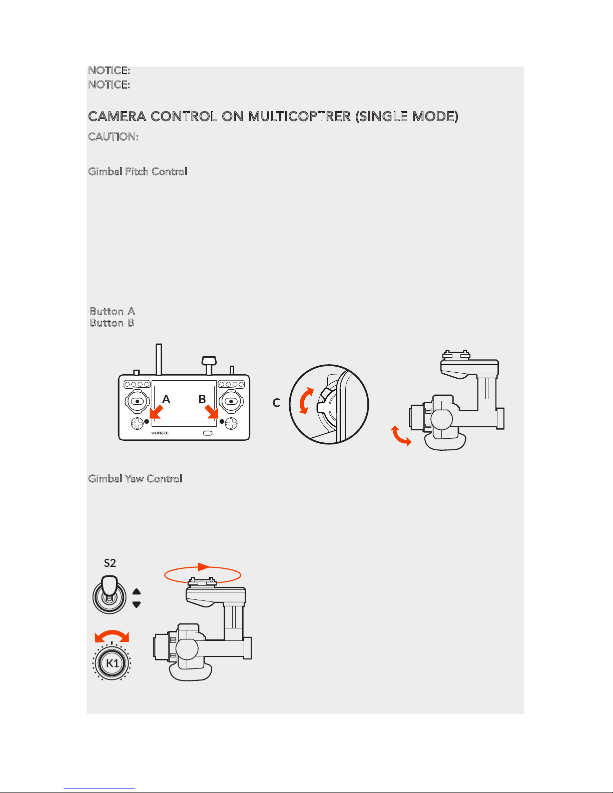
CAMERA CONTROL ON MULTICOPTRER (SINGLE MODE)
CAUTION: The gimbal can only be controlled through ST24 When being attached to H920.
Gimbal Pitch Control
Gimbal Pitch Control
There is a gimbal pitch mode switch on ST24---S1. When the switch is in up/middle position,
the CGO4 gimbal camera is in Angle Mode. Use the slider on the left side of the ST24 to set
the pitch/tilt position of the gimbal camera. When the S1 is in bottom position, the gimbal
camera is in Velocity Mode. When the slider is in the middle position, it means the velocity
rate is 0 for the CGO4 gimbal camera, and it will stop pitching up/down. When the slider is
above the middle position, the CGO4 will start pitching up. When the slider is below the
middle position, the CGO4 will start pitching down. The distance between the slider and the
middle position decides the velocity rate, the further distance, the higher velocity it would be.
Gimbal Yaw Control
There is a gimbal yaw mode switch on ST24---S2. When the switch position is up and
middle, the gimbal camera is in Follow Mode. The yaw control of the gimbal camera
is now disabled. The gimbal camera will adjust its yaw direction according to the
aircraft’s movements. When the switch position is down, the gimbal camera is in
NOTICE:
We recommend users to power on the aircraft in the angle mode.
NOTICE: When returns back to the FPV interface, you will hear two long beeps. That means
the binding is complete. The Real-time images can now be seen on the screen.
Button A = Take Still Photo
Button B = Start/Stop Recording Video
6
Global Mode. The Gimbal Yaw control knob
(K1) is now activated.
When the user rotates the knob in the right
direction, the gimbal camera will rotate to
the right side, and vice versa.
Page 9

7
BINDING CGO4 GIMBAL CAMERA TO THE ST24 (TEAM MODE)
STEP 1): Power on the ST24, tap [ ] to go to the main interface.
STEP 2): Switch on the TORNADO H920. Wait until the gimbal LED blinks green. That means
the Wi-Fi has been started up.
STEP 3): Tap System Settings icon to enter the Bind interface.
STEP 4): Tap the Refresh icon, and the code of the Aircraft Model (it indicates the code of the
CGO4 receiver) and Camera will both be shown on the screen. Select the right codes and tap
the Bind icon. Tap OK when a pop-up window comes out.
NOTICE: If it is the first time to bind your CGO4 gimbal camera to the ST24, you need to
insert the password: 1234567890. Press OK on the pop-up window to continue.
STEP 5): Tap Camera Select and select CGO4, and then tap Select.
STEP 6): Tap “OK” to confirm the setting and tap [ ] to go back to the flight control interface.
BINDING H920 MULTICOPTER TO THE ST12 (TEAM MODE)
STEP 1): Power on the ST12 and tap “RC” on the main interface
STEP 2): Tap Model Select and if required press “OK” to bypass any pop up warning/alerts.
STEP 3): Tap to create a new model and if required press “OK” to bypass any pop up
warnings/alerts.
STEP 4): Tap Flight Settings and if required press “OK” to bypass any pop up warnings/alerts.
STEP 5): Lift the H920 back end upward approximately 45° , then back down to “level” twice
till the main LED indicator blinks yellow.
STEP 6): Tap the Refresh icon. Select the code of the H920 listed in the column under
”Model” and tap Bind ,then tap “OK” after the connection has been established
STEP 7): When tapping, you will hear two long beeps from the aircraft. That means the ST12
is bound to the H920 successfully.
Model: 4K Welcome,Pilot 10:48:28 pm
10
SR24_16042
SR24_16042
Not connected
Model Camera
Model: 4K Welcome,Pilot 10:48:28 pm
10
Model Select
New Model TORNADO H920
Page 10

8
CAMERA CONTROL ON MULTICOPTER (TEAM MODE)
GIMBAL PITCH CONTROL
There is a gimbal pitch mode switch on ST24---S1. When the switch is in up/middle position,
the gimbal camera is in Angle Mode. Use K5 to set the pitch/tilt position of the gimbal
camera. When the S1 is in bottom position, the gimbal camera
is in Velocity Mode. When the right-hand stick is in the middle
position, it means the velocity rate is 0 for the CGO4, and it
will stop pitching up/down. When the right-hand stick is above
the middle position, the CGO4 will start pitching up. When the
right-hand stick is below the middle position, the CGO4 will
start pitching down. The distance between the right-hand stick
and the middle position decides the velocity rate, the further
distance, the higher velocity it would be.
GIMBAL YAW CONTROL
There is a gimbal yaw mode switch on ST24---S2. When the switch position is up, the gimbal
camera is in Follow Mode. The yaw control of the gimbal camera is now disabled; when the
switch is in the middle position, the gimbal camera is still in Follow Mode, however, at this
time, the yaw control is activated. The gimbal camera will adjust its yaw direction according
to the aircraft’s movements. When the switch position is down, the gimbal camera is in Global
Mode. The Aileron/Roll Control and Elevator/Pitch Control of the right-hand stick take
control of the CGO4 in yaw and pitch directions.
NOTICE: When the CGO4 is attached to the TORNADO H920, the control knob (K6) is
activated. Users can zoom in by rotating the knob (K6) in the clockwise direction (the movement speed of the CGO4 gimbal camera in pitch and yaw directions will become slow in the
velocity mode), and vice versa (the movement speed of the CGO4 gimbal camera in pitch and
yaw directions will become fast in the velocity mode).
CAUTION: Each time the K6 is pushed to a certain position, it should be pushed back to the
middle position to confirm the setting. Otherwise, the gimbal camera will continue to zoom
in/out until it achieves the maximum/minimum value.
STEP 8):
Tap [ ] twice to return to the main screen and the model /receiver should automat-
ically connect to ST12
NOTICE: The H920 main LED indicator will blink red and white if the TORNADO loses GPS
signal /lock. The H920 main LED indicator will be solid color of the current mode if the GPS
signal/lock is acquired.
S2
Page 11

9
PHOTO TAKING AND VIDEO RECORDING
ST24 seamlessly integrates control of CGO4 gimbal camera so that you can easily take still
photos and start/stop video recording through corresponding buttons.
CAUTION: If CGO4 is carried on H920, it can only be controlled through ST24.
TO TAKE PHOTOS
Press the button located on the left side of ST24. You’ll hear an audible ‘shutter’ sound from
ST24 and it will take approximately 5 seconds to capture the photo before you can take
another photo.
NOTE: You cannot take still photos during video recording.
NOTE: You must stop video-recording in order to take photos.
TO START/STOP VIDEO-RECORDING
Press the button located on the right side of ST24. You’ll hear
an audible indication from ST24 each time the recording
starts/stops. And while video is recording, there will be a red
dot next to the video-recording timer near the upper
right-hand corner of ST24.
CAUTION: If the video is being recorded on ProAction, repress
the video recording button to end the process; otherwise, the
video is unable to be saved.
(A) = To take photos
(B) = To record videos
CGO4 INTERFACE (ST24)
Welcome, Pilot
GPS
N/A
SAT
N/A
POS
N/A E
N/A N
MODE
N/A
VOLTS
ALT
G-SPD
DIS
System Sengs
00:00:00
Model Select
N/AV
N/Am
N/A KPH
N/A m
STD
4K
30
p
4:3
On
MODE
P
WB
ISO
200
-2/3
F3.5
1/60s
9:43:31 pm
Channel Settings
AFS
H
Model: H920 CGO4
01 02 03 04 05 06 07
01. CAMERA SWITCH 02. CAMERA MODE 03. WHITE BALANCE 04. ISO SENSITIVITY
05. EXPOSURE VALUE 06. APERTURE/SHUTTER SPEED 07. MENU SETTING
Page 12

10
CAMERA MODE INTRODUCTION
The CGO4 gimbal camera has eight camera modes in total,providing photographers with a
multiple of choices for different shooting scenes.
INTELLIGENT AUTO MODE: The subjects are recorded using settings automatically
selected by the camera.
NOTE: In this mode, the camera makes the optimal settings for the subject and scene,
so we recommend it when you wish to leave the settings to the camera and record
without thinking about them.
NOTICE: [iA] is set if none of the scene are applicable, and the standard settings are set.
INTELLIGENT AUTO PLUS MODE: Allows you to adjust the brightness and color hue
when in Intelligent Auto Mode.
PROGRAM AE MODE:
The camera automatically sets the shutter speed and the
aperture value according to the brightness of the subject.
You can take picture with greater freedom by changing various settings in the Menu Settings.
CAUTION: The Aperture and Shutter Speed cannot be adjusted separately under P
mode; it can only be controlled through the Union Picker.
APERTURE-PRIORITY AE MODE:
The shutter speed is automatically determined
by the aperture value you set.
SHUTTER-PRIORITY AE MODE: The aperture value is automatically determined
by the shutter speed you set.
MANUAL EXPOSURE MODE: The exposure is adjusted by the aperture value and
the shutter speed which are manually adjusted
PROGRAM AE MODE:
Records at the aperture value and shutter speed set by
the camera. The camera automatically sets the shutter speed and the aperture
value according to the brightness of the subject during video-recording.
You can take picture with greater freedom by changing various settings in the
Menu Settings.
SHUTTER-PRIORITY AE MODE:
When you set the shutter speed, the camera
automatically optimizes the aperture value for the brightness of the subject
during video-recording.
Changing the brightness Available Not Available
Changing the hue Available Not Available
IA+ (INTELLIGENT AUTO PLUS MODE) IA (INTELLIGENT AUTO MODE)
S
P
The following two modes are under Creative Movie Mode:
Page 13

ADJUSTING THE WHITE BALANCE
In sunlight, under incandescent lights or in other such conditions where the color of white
takes on a reddish or bluish tinge, this item adjusts to the color of white which is closest to
what is seen by the eye in accordance with light source.
SETTING THE LIGHT SENSITIVITY
This allows the sensitivity to light (ISO sensitivity) to be set.
Setting to a higher figure enables pictures to be taken even in
dark places without the resulting pictures coming out.
COMPENSATING THE EXPOSURE
Exposure Value (EV) is a number that represents a combination of camera’s shutter speed and
f-number.Use this function when you cannot achieve appropriate exposure due to the difference in
brightness between the subject and the background.
SPECIFYING THE APERTURE/ SHUTTER SPEED
NOTICE: The effect of the set aperture value and shutter speed
will not be visible on the recording screen.
NOTE:If the photographer wants to highlight the background,
set a relatively high aperture value; if the photographer wants a
soft background, set a relatively low level.
NOTICE:
It will operate as [AWB] during motion picture recording.
AWB:
Automatic Adjustment Daylight: When taking pictures outdoors under a clear sky
Cloudy: When taking pictures under a cloudy sky Shade: When taking pictures outdoors in
the shade Halogon: When taking pictures under the incandescent lights
AWB
Daylight
Cloudy
Halogon
Shade
ISO
ISO 200
ISO 400
ISO 800
Aperture
Union
Shuer Speed
F3.5
F4.0
1/10s
1/13s
1/8s
---
---
Auto / Intelligent ISO (i-ISO) /100 (Extended) /200/400 /800/
1600/3200/6400/12800/25600(changeable to 1/3 EV STEP)(Up to
ISO 6400 in motion picture recording)(ISO Auto in M mode)
Exposure Compensation 1/3 EV STEP +/-5EV(+/-3 EV for motion picture
Exposure Accuracy +/- 1/3 EV
Maximum Aperture F3.5(Wide)~F5.6(Tele)
Minimum Aperture F22
11
Page 14

MENU SETTING INTRODUCTION
VIDEO SYSTEM
This allows you to set different system frequency. In different system frequencies, the video
qualities are different.
NTSC 4K/100M/30P; FHD/28M/60P; FHD/20M/30P; HD/10M/30P; VGA/4M/30P
PAL
4K/100M/25P; FHD/28M/50P; FHD/20M/25P; HD/10M/25P; VGA/4M/25P
CINEMA
C4K/100M/24P; 4K/100M/24P; FHD/ALL-intra/200M/24P; FHD/50M/24P
MP4 The MP4 data format is suitable for playback on a PC, etc.
MP4(LPCM)
The MP4 data format for image editing
MOV
Data format for image editing.
Mechanical Shutter Speed [Still image] Bulb(Max. 60minutes),1/8000-60 [Motion picture]: 59.94Hz:
1/16,ooo-1/30; 50.00Hz: 1/16,ooo-1/25; 23.98Hz: 1/16,ooo-1/24
Shutter Life Approx.200,000 images
Burst speed MECHANICAL SHUTTER: H: 12 frames/sec(AFS), 7 frames/sec(AFC)
M: 7 frames/sec(Live View) L: 2 frames/sec(Live View)
Electronic shutter: SH: 4O frames/sec
NOTE: If the photographer wants to capture fast-move subjects, set a relatively high shutter
speed; if the photographer wants to track-shooting, set a relatively low shutter speed.
When CGO4 gimbal camera is in Aperture-Priority AE Mode, the camera automatically
optimizes the shutter speed for the brightness of the subject.
When CG04 gimbal camera is in shutter-priority AE Mode, the camera automatically optimizes
the aperture value for the brightness of the subject.
When CGO4 gimbal camera is in Manual Exposure Mode: the photographer can determine
First, tap Mode button on the lower portion of the screen and a virtual mode dial will pop up
on the screen and then set the mode dial to [M].Slide the aperture value picker and shutter
speed picker to set the appropriate aperture value and shutter speed.
VIDEO ENCODING
This allows you to set different video formats.
IMAGE SIZE
This sets the number of pixels. The higher the numbers of pixels, the finer the detail of the
pictures will appear even when they are printed onto large sheets. (16M/8M/4M)
IMAGE FORMAT
This sets the file format for the pictures you take.
(Fine / Standard / RAW+ fine / RAW+ / standard RAW)
VIDEO QUALITY
This sets up the picture quality for motion pictures:
OPTIONS: MP4 30P 100Mbps 4K; MP4 24P 100Mbps 4K; MP4 60P 28Mbps 4K; MP4 30P 20M
12
Page 15

Angle of view
Focal Length
Wide(f=14mm):75°~Tele(f=42mm):29°
F=14mm-42mm
PHOTO STYLE
This selects effects to match the type of image you wish to record and adjust the color and
image quality of the effects.(Standard / Vivid / Natural / Monochrome / Scenery / Portrait)
FOCUS MODE
By setting the optimum Focus Mode for the subject or recording condition, you can let the
camera automatically adjust focus in various scenes.
MANUAL FOCUS MODE
Use this function when you want to fix the focus or when the distance between the lens and
the subject is determined and you do not want to achieve Auto Focus.
NOTE:
The maximum/minimum/current value will be displayed on the up right corner of the screen.
AF MODE
This allows the focusing method that suits the positions and number of the subjects to be selected.
IMAGE FORMAT
CAUTION: If you delete a RAW file from the camera, the corresponding JPEG image will also be deleted.
NOTICE: It is fixed to maximum recordable pixels [L] for each image aspect ratio.
ASPECT RATIO
This allows you to select the aspect ratio of the pictures to suit printing or the playback method.
NOTICE:
The ends of the recorded pictures may be cut at printing so check before printing.
4:3
3:2
16:9
[Aspect Ratio] of a 4:3 TV 4608x3456 (16M) ; 3264X2448 (8M); 2336X1752 (4M)
1:1
[Aspect Ratio] of a 35mm film camera
[Aspect Ratio] of a high-definition TV, etc
Spare aspect ratio
4608X3072 (14M); 3264X2176 (7M); 2336X1560 (3.5M)
4608x2592; 3804x2156; 1920X1080
3456X3456; 2448X2448; 1744X1744
1-Area:
The camera focuses on the subject in the AF area on the center of the screen.Position and Size of
the AF area can be changed.
49 point:
Up to 49 AF areas can be focused.This is effective when a subject is not in the center of the screen.
You can select areas to be in focus.
Touch the eye to be in focus: touch the eye in the yellow frame. If you touch any other location, the AF area
setting screen will be displayed.
13
AFS
Focus Mode Continuous AF Description of settings
MF
ON: The camera automatically keeps focusing on subjects during recording.
OFF:
The camera maintains the focus position at the start of recording.
ON / OFF:
You can focus manually. A focus bar will pop up on the left side of the
screen for users to adjust the value.
Page 16

PHOTO STYLE
You can select effects to match the type of image you wish to record. You can adjust the color
and image quality of the effects.
STANDARD / VIVID / NATURAL / MONOCHROME / SCENERY / PORTRAIT
DRIVE MODE
Slide the menu and select Drive Mode. A menu will pop up with two menu items: Normal,
Burst for the photographer to select with.
LIGHT METERING
The photographer can set the light metering method for still for measuring brightness.
[Multiple] This is the method in which the camera measures the most suitable exposure by
judging the allocation of brightness on the whole screen automatically. Usually, we recommend using this method.
[Center Weighted] This is the method used to focus on the subject on the center of the screen
and measure the whole screen evenly.
[Spot] This is the method to measure the subject in the spot metering target.
Taking pictures using Burst Mode
Pictures taken with a burst speed of [SH] will be recorded as a single burst group.
Slide the Menu and Select Driving Mode. Focus on the subject and take a picture.
Changing the burst speed
Pictures taken with a burst speed of [SH] will be recorded as a single burst group.
Slide the Menu and Select Driving Mode. Focus on the subject and take a picture.
NORMAL When the shutter button is pressed, only one picture is recorded.
BURST
Recordings are made in succession while the shutter button is pressed
[L] (Low Speed)[M] (Middle Speed)[H] (High Speed)
12(AFS) 7(AFC) 7 2
None Available Available
BURST SPEED(PICTURES/SECOND)
LIVE VIEW DURING BURST MODE
14
Page 17

GROUND IMAGING SOLUTION
APP DOWNLOADING
Download the free APP named CGO4 to smart device at the APP Store or Google Play Store.
Install the APP to your 5.8GHz Wi-Fi capable device. Make a note of the network name and
password located on the top of the gimbal assembly.
CGO4 APP COMPATIBLE DEVICES:
APPLE IOS: IOS 7.0 or above
ANDROID: Android 4.2 or above
ATTACHING CGO4 GIMBAL CAMERA TO PROACTION
STEP 1): Securely attach CGO4 gimbal camera to ProAction with Gimbal Thumb Screws, then
withdraw the Gimbal Cord from the left side.
STEP 2): Insert the Gimbal Cord into the center carrying handle socket.
STEP 3): Install the ProAction Battery and engage the connector properly.
STEP 4): Erect the phone holder and install the mobile phone into it, and
then you can make Wi-Fi connection between CGO4 and mobile device.
BINDING CGO4 GIMBAL CAMERA TO APP
The APP seamlessly integrates control of CGO4 gimbal camera so that you can see exactly
what your camera sees with a live HD video feed right on your mobile device. It makes you
feel as though the camera is right in your hands.
CAUTION: If the user wants to take photos or videos through ProAction, CGO4 APP should
be downloaded beforehand.
STEP 1): Make Wi-Fi connection between your mobile device: Select the correct Wi-Fi SSID
and enter the password: “1234567890”
STEP 2): Tap the CGO4 icon on your mobile device and enter the APP interface.
GiMBAL CONTROL ON PROACTION
There are two modes to control the Gimbal through ProAction: Follow Mode and Global Mode.
Switch on the ProAction on a flat and stable surface. Do not move, sway or shake the ProAction during initialization. After initialization, the gimbal will boot up normally in either Follow
or Global Mode, depending on user settings on the left-hand switches of the ProAction.
Once the gimbal is on, it begins an automatic self-check by rotating about the yaw axis. At
this time, the power indicator will be on as well. At the same time the control status LED will
blink green and blue alternately.
15
Page 18

When the self-check (start-up) process is complete, the Control Status LED will grow solid
blue. The user can switch freely between Follow Mode and Global Mode without powering
off the gimbal.
FOLLOW MODE
In Follow Mode, the camera lens moves in the direction of ProAction. The user can only
manipulate the pitch direction through Gimbal Control Stick on the right.
If the Gimbal Control Stick moves upward, the camera lens will trim itself up. If the Gimbal
Control Stick moves downward, the camera lens will trim itself down.
NOTICE: In Follow Mode, the camera lens will move in the direction of the Gimbal. At this
time, the Gimbal will take control of itself in the Yaw direction and the user can only control
the Gimbal in the Pitch direction.
NOTICE: The Yaw Axis inside the Gimbal will rotate in the direction of ProAction Frame. Any
manipulation in the Yaw direction is invalid, in other words, the user can only control the Pitch
direction.
GLOBAL MODE
In Global Mode, the camera lens sticks to a fixed direction instead of following the movement
of the ProAction Frame. The user can control the Yaw and Pitch Direction through Gimbal
Control Stick.
If the Gimbal Control Stick moves upward, the camera lens will trim itself up. If the Gimbal
Control Stick moves downward, the camera lens will trim itself down. If the Gimbal Control
Stick turns right, the camera lens will trim itself to the right. If the Gimbal Control Stick turns
left, the camera lens will trim itself to the left.
DOUBLE HANDS OPERATING:
Grip the left and right handles of the ProAction™ with both hands. The Power and Mode
Selection Switch is on the left side, while the Gimbal Control Stick is on the right side.
NOTICE: Once the ProAction™ is started up, no matter which mode it is in, the default mode
is Double Hands Operating. The Control Status Indicator on center carrying handle will be
solid red. The user can ONLY take control of the gimbal through Gimbal Control Stick on the
right side.
Double Hands Operating Method
In the Follow Mode, the camera lens track the ProAction™ in
Yaw axis. The user can only control the pitch direction through
Gimbal Control Stick on the right.
Move the Gimbal Control Stick upward to trim the camera lens
up. Move the Gimbal Control Stick downward to trim the
camera lens down.
In the Global Mode, the camera lens does not move in the
direction of the ProAction™ Frame but sticks to a fixed
direction. The user can control both the Yaw and Pitch
directions through Gimbal Control Stick.
Move the Gimbal Control Stick upward/downward to trim the
camera lens up/down. Move the Gimbal Control Stick to the
left/right to trim the camera lens left/right.
NOTICE: When in the Follow Mode, the Gimbal Control Stick
can't control the GB603 in Yaw axis. When in the Global
Mode, the Gimbal Control Stick can control the GB603 in
Pitch and Yaw axes.
16
Page 19

SINGLE HAND OPERATING:
Lift the center carrying handle with one hand. When holding the ProAction™ with single
hand, press and hold the Function Switch Button in the rear of the Pitch Control Wheel. The
Control Status Indicator will glow solid blue when successfully switched.
The control right has been switched to the Pitch Control Wheel on the center carrying handle.
The Gimbal Control Stick on the right side of the ProAction™ is disabled in Pitch direction.
NOTICE: When the user holds the ProAction™ with single hand in the Global Mode, the user
can control the camera in the Yaw direction through the Gimbal Control Stick.
Single Hand Operating Method
Roll the Pitch Control Wheel forward to move the
camera pitch/angle downward, and roll the Pitch
Control Wheel backward to move the camera
pitch/angle upward.
ANGLE LIMITS
When operating the ProAction™, it is suggested
to hold it horizontally for better photography
experience, or at least to make sure the roll angle
is less than 40 degree.
17
Page 20

PHOTO TAKING AND VIDEO RECORDING
TO TAKE PHOTOS
STEP 1): Tap the APP icon on your mobile device and you’ll come to the Camera Control Interface.
STEP 2): Press “Camera” and CGO4 gimbal camera will be ready to work.
STEP 3): Press the [ ] button and you can start to take photos.
NOTICE: If you have successfully entered photo-taking, an audible ‘shutter’ sound will be
heard and a notice will pop up on the screen, reading “picture of success”
CAUTION: You cannot take photos while recording video. You must stop recording video in
order to take still photos.
TO START/STOP VIDEO RECORDING
Press [ ] button and you can start to record the video.
If you have successfully entered video-recording, the button will turn red and a video
recording timer will appear on the top right corner of the screen.
CAUTION: If the video is being recorded, repress the video recording button to end the
process before powering off the gimbal, or the video is unable to be saved.
APP INTERFACE
01
05
06
07
08
10
02
03
04
01. WHITE BALANCE 02. EXPOSURE VALUE/ISO SENSITIVITY 03. APERTURE/SHUTTER SPEED
04. FULL SCREEN DISPLAY 05. FOCAL LENGTH 06. CONTROL MENU 07. VIDEO-RECORDING
08. BUTTONPHOTO-TAKING BUTTON 09. LEFT STORAGE 10. SETTING MENU
A
STD
4K
30
p
4:3
AFS
YUNEEC_81004F
16:55:08
AWB
5739 pic
EV:
Len:
F: SS:
09
18
Page 21

19
ADJUSTING THE WHITE BALANCE
In sunlight, under incandescent lights or in other such conditions where the color of white
takes on a reddish or bluish tinge, this item adjusts to the color of white which is closest to
what is seen by the eye in accordance with light source.
CAMERA MODE INTRODUCTION
The CGO4 gimbal camera has eight camera modes in total,providing photographers with a
multiple of choices for different shooting scenes.
INTELLIGENT AUTO MODE: The subjects are recorded using settings automatically
selected by the camera.
NOTE: In this mode, the camera makes the optimal settings for the subject and scene,
so we recommend it when you wish to leave the settings to the camera and record
without thinking about them.
NOTICE: [iA] is set if none of the scene are applicable, and the standard settings are set.
INTELLIGENT AUTO PLUS MODE: Allows you to adjust the brightness and color hue
when in Intelligent Auto Mode.
PROGRAM AE MODE:
Records at the aperture value and shutter speed set by the camera.
The camera automatically sets the shutter speed and the aperture value according to
the brightness of the subject.
You can take picture with greater freedom by changing various settings in the Menu Settings.
CAUTION: The Aperture and Shutter Speed cannot be adjusted separately under P
mode; it can only be controlled through the Union Picker.
APERTURE-PRIORITY AE MODE:
The shutter speed is automatically determined by the
aperture value you set.
SHUTTER-PRIORITY AE MODE: When you set the shutter speed, the camera automatically
optimizes the aperture value for the brightness of the subject.
MANUAL EXPOSURE MODE: The exposure is adjusted by the aperture value and the
shutter speed which are manually adjusted
PROGRAM AE MODE:
Records at the aperture value and shutter speed set by
the camera. The camera automatically sets the shutter speed and the aperture
value according to the brightness of the subject during video-recording.
You can take picture with greater freedom by changing various settings in the
Menu Settings.
SHUTTER-PRIORITY AE MODE:
When you set the shutter speed, the camera
automatically optimizes the aperture value for the brightness of the subject
during video-recording.
Changing the brightness Available Not Available
Changing the hue Available Not Available
IA+ (INTELLIGENT AUTO PLUS MODE) IA (INTELLIGENT AUTO MODE)
S
P
The following two modes are under Creative Movie Mode:
Page 22

20
SETTING THE LIGHT SENSITIVITY
This allows the sensitivity to light (ISO sensitivity) to be set.
Setting to a higher figure enables pictures to be taken even in
dark places without the resulting pictures coming out.
COMPENSATING THE EXPOSURE
Exposure Value (EV) is a number that represents a combination of camera’s shutter speed and
f-number.Use this function when you cannot achieve appropriate exposure due to the difference in
brightness between the subject and the background.
SPECIFYING THE APERTURE/ SHUTTER SPEED
NOTICE: The effect of the set aperture value and shutter speed
will not be visible on the recording screen.
NOTE:If the photographer wants to highlight the background,
set a relatively high aperture value; if the photographer wants a
soft background, set a relatively low level.
NOTICE:
It will operate as [AWB] during motion picture recording.
AWB:
Automatic Adjustment Daylight: When taking pictures outdoors under a clear sky
Cloudy: When taking pictures under a cloudy sky Shade: When taking pictures outdoors in
the shade Halogon: When taking pictures under the incandescent lights
AWB
Daylight
Cloudy
Halogon
Shade
Exposure Compensation 1/3 EV STEP +/-5EV(+/-3 EV for motion picture
Exposure Accuracy +/- 1/3 EV
Maximum Aperture F3.5(Wide)~F5.6(Tele)
Minimum Aperture F22
NOTE: If the photographer wants to capture fast-move subjects, set a relatively high shutter
speed; if the photographer wants to track-shooting, set a relatively low shutter speed.
When CGO4 gimbal camera is in Aperture-Priority AE Mode, the camera automatically
optimizes the shutter speed for the brightness of the subject.
When CG04 gimbal camera is in shutter-priority AE Mode, the camera automatically optimizes
the aperture value for the brightness of the subject.
Mechanical Shutter Speed [Still image] Bulb(Max. 60minutes),1/8000-60 [Motion picture]: 59.94Hz:
1/16,ooo-1/30; 50.00Hz: 1/16,ooo-1/25; 23.98Hz: 1/16,ooo-1/24
Shutter Life Approx.200,000 images
Burst speed MECHANICAL SHUTTER: H: 12 frames/sec(AFS), 7 frames/sec(AFC)
M: 7 frames/sec(Live View) L: 2 frames/sec(Live View)
Electronic shutter: SH: 4O frames/sec
ISO
ISO 200
ISO 400
ISO 800
Aperture
Union
Shuer Speed
F3.5
F4.0
1/10s
1/13s
1/8s
---
---
Auto / Intelligent ISO (i-ISO) /100 (Extended) /200/400 /800/
1600/3200/6400/12800/25600(changeable to 1/3 EV STEP)(Up to
ISO 6400 in motion picture recording)(ISO Auto in M mode)
Page 23

MENU SETTING INTRODUCTION
VIDEO SYSTEM
This allows you to set different system frequency. In different system frequencies, the video
qualities are different.
ADJUSTING THE FOCAL LENGTH
Use this function when you want to fix the focus or when the distance between the lens and
the subject is determined and you do not want to achieve Auto Focus.
CONTROL MENU INTRODUCTION
FIXING THE FOCUS AND THE EXPOSURE (AF/AE LOCK)
This is useful when you want to take a picture of a subject outside the AF area or the contrast
is too strong and you cannot achieve appropriate exposure.
[AE LOCK] Only the exposure is locked. When the exposure is set, [AEL],the aperture value,
the shutter speed are displayed.
[AF LOCK] Only the focus is locked. When the subject is focused,[AFL],the focus indication,
the aperture value and the shutter speed are displayed.
[AF/AE LOCK] Both focus and exposure are locked. [AFL],[AEL],the focus indication, aperture
value and shutter speed are displayed when the focus and the exposure are optimized.
[AF-ON] Auto Focus is performed.
CAMERA-S
This allows you to switch on/off the camera when operating CGO4 on ProAction.
STEP 1): Tap [ ] icon on the right-hand column and tap “Camera-S”
STEP 2): A camera setting bar will pop up on the screen.
STEP 3): Slide the Camera ON/OFF switch to the right to turn on the camera.
STEP 4): Slide the Camera ON/OFF switch to the left to turn off the camera.
GUIDELINESS:
When there are obstacles, the position judgment of the photographer may be biased. The
guidelines function can help to correct their judgment in the horizontal and vertical direction
and to create a better photo composition.
STEP 1): Tap [ ] icon on the right-hand column and tap “Guidelines”.
STEP 2): A guideline status menu will pop up on the screen.
STEP 3): Slide the guideline switch to the right to turn on the camera.
STEP 4}: Slide the guideline switch to the left to turn off the camera.
Angle of view Wide(f=14mm):75°~Tele(f=42mm):29°
Focal Length F=14mm-42mm
21
NTSC 4K/100M/30P; FHD/28M/60P; FHD/20M/30P; HD/10M/30P; VGA/4M/30P
PAL
4K/100M/25P; FHD/28M/50P; FHD/20M/25P; HD/10M/25P; VGA/4M/25P
CINEMA
C4K/100M/24P; 4K/100M/24P; FHD/ALL-intra/200M/24P; FHD/50M/24P
When CGO4 gimbal camera is in Manual Exposure Mode: the photographer can determine
First, tap Mode button on the lower portion of the screen and a virtual mode dial will pop up
on the screen and then set the mode dial to [M].Slide the aperture value picker and shutter
speed picker to set the appropriate aperture value and shutter speed.
Page 24

PHOTO STYLE
This selects effects to match the type of image you wish to record and adjust the color and
image quality of the effects.(Standard / Vivid / Natural / Monochrome / Scenery / Portrait)
ASPECT RATIO
This allows you to select the aspect ratio of the pictures to suit printing or the playback method.
NOTICE:
The ends of the recorded pictures may be cut at printing so check before printing.
4:3
3:2
16:9
[Aspect Ratio] of a 4:3 TV 4608x3456 (16M) ; 3264X2448 (8M); 2336X1752 (4M)
1:1
[Aspect Ratio] of a 35mm film camera
[Aspect Ratio] of a high-definition TV, etc
Spare aspect ratio
4608X3072 (14M); 3264X2176 (7M); 2336X1560 (3.5M)
4608x2592; 3804x2156; 1920X1080
3456X3456; 2448X2448; 1744X1744
22
MP4 The MP4 data format is suitable for playback on a PC, etc.
MP4(LPCM)
The MP4 data format for image editing
MOV
Data format for image editing.
VIDEO ENCODING
This allows you to set different video formats.
IMAGE SIZE
This sets the number of pixels. The higher the numbers of pixels, the finer the detail of the
pictures will appear even when they are printed onto large sheets. (16M/8M/4M)
IMAGE FORMAT
This sets the file format for the pictures you take.
(Fine / Standard / RAW+ fine / RAW+ / standard RAW)
VIDEO QUALITY
This sets up the picture quality for motion pictures:
OPTIONS: MP4 30P 100Mbps 4K; MP4 24P 100Mbps 4K; MP4 60P 28Mbps 4K; MP4 30P 20M
Angle of view
Focal Length
Wide(f=14mm):75°~Tele(f=42mm):29°
F=14mm-42mm
FOCUS MODE
By setting the optimum Focus Mode for the subject or recording condition, you can let the
camera automatically adjust focus in various scenes.
MANUAL FOCUS MODE
Use this function when you want to fix the focus or when the distance between the lens and
the subject is determined and you do not want to achieve Auto Focus.
NOTE:
The maximum/minimum/current value will be displayed on the up right corner of the screen.
AFS
Focus Mode Continuous AF Description of settings
MF
ON: The camera automatically keeps focusing on subjects during recording.
OFF:
The camera maintains the focus position at the start of recording.
ON / OFF:
You can focus manually. A focus bar will pop up on the left side of the
screen for users to adjust the value.
Page 25

PHOTO STYLE
You can select effects to match the type of image you wish to record. You can adjust the color
and image quality of the effects.
STANDARD / VIVID / NATURAL / MONOCHROME / SCENERY / PORTRAIT
DRIVE MODE
Slide the menu and select Light Metering. A menu will pop up with three menu items:
Multiple, Center Weighted, Spot for the photographer to select with.
LIGHT METERING
The photographer can set the light metering method for still for measuring brightness.
[Multiple] This is the method in which the camera measures the most suitable exposure by
judging the allocation of brightness on the whole screen automatically. Usually, we recommend using this method.
[Center Weighted] This is the method used to focus on the subject on the center of the screen
and measure the whole screen evenly.
[Spot] This is the method to measure the subject in the spot metering target.
Taking pictures using Burst Mode
Pictures taken with a burst speed of [SH] will be recorded as a single burst group.
Slide the Menu and Select Driving Mode. Focus on the subject and take a picture.
Changing the burst speed
Pictures taken with a burst speed of [SH] will be recorded as a single burst group.
Slide the Menu and Select Driving Mode. Focus on the subject and take a picture.
NORMAL When the shutter button is pressed, only one picture is recorded.
BURST
Recordings are made in succession while the shutter button is pressed
AF MODE
This allows the focusing method that suits the positions and number of the subjects to be selected.
IMAGE FORMAT
CAUTION: If you delete a RAW file from the camera, the corresponding JPEG image will also be deleted.
NOTICE: It is fixed to maximum recordable pixels [L] for each image aspect ratio.
[L] (Low Speed)[M] (Middle Speed)[H] (High Speed)
12(AFS) 7(AFC) 7 2
None Available Available
BURST SPEED(PICTURES/SECOND)
LIVE VIEW DURING BURST MODE
Focus and exposure will keep on following the subject even if it moves.
1-Area: The camera focuses on the subject in the AF area on the center of the screen.Position
and Size of the AF area can be changed.
49 point: Up to 49 AF areas can be focused.This is effective when a subject is not in the center of the
screen.You can select areas to be in focus.
Touch the eye to be in focus: touch the eye in the yellow frame. If you touch any other
location, the AF area setting screen will be displayed.
23
Page 26

DISCLAIMER
Yuneec Electric Aviation cannot be held liable for any damage, injury or for use of the product
in violation with legal regulations, especially in the following circumstances:
Damage and/or injury as well violation of legal regulations resulting from a failure to comply
with the operating instructions or the instructions at www.yuneec.com, product information,
user manual and other legally binding information.
Damage and/or injury as well violation of legal regulations brought about by the influence of
alcohol, drugs, medication or other narcotics which may impact on the concentration of the user.
The same applies to illnesses effecting the concentration of the user (dizziness, tiredness,
nausea etc.) or other factors compromising mental and physical capabilities.
Intentionally caused damage, injury or violation of legal regulations.
Any request for compensation caused by an accident resulting from use of the product.
Damage and/or injury as well as violation of legal regulations caused by use of the product in
a no-fly zone, e.g. next to an airfield, above a motorway or a natural conservation area.
Malfunction of the product caused by retrofitting or replacement with components which did
not come from YuneecElectric Aviation.
Damage and/or injury caused by the use of replica parts (non-original parts).
Damage and/or injury as well as violation of legal regulations caused by incorrect operation
or misjudgement.
Damage and/or injury caused by damaged spare parts or not using original Yuneec Electric
Aviation spare parts.
Damage and/or injury as well as violation of legal regulations caused by ignoring the low
voltage battery warning.
Damage and/or injury caused by knowingly and negligibly flying with a damaged model or
one which is unfit to fly, e.g. due to dirt, water penetration, coarse particles, oil or a model
which has not been correctly or completely assembled or if the main components exhibit
visible damage, defects or missing parts.
Damage and/or injury as well as violation of legal regulations caused by operating the model
in a magnetic field (e.g. high voltage lines, electricity/transformer stations, radio towers,
mobile phone masts etc.), a strong wireless signal environment,no-fly zones, poor visibility
and in the event of vision impairments or other impacts on the pilot which are left unchecked etc...
Damage and/or injury brought about through a violation of the legal regulations for operating the model, in unsuitable weather conditions, e.g. rain, wind, snow, hail, storms, hurricanes etc.
Damage and/or injury as well as violation of legal regulations caused by force majeure, e.g.
collision, fire, explosion,flooding, tsunami, landslide, avalanche, earthquake or other forces of
nature.
Damage and/or injury as well as violation of legal regulations caused by the illegal or immoral
use of the model, e.g. capturing videos or recording data which infringes upon/harms the
privacy of other people.
Damage and/or injury as well as violation of legal regulations caused by incorrect use of the
batteries, protection systems, chargers or aircraft.
Consequential damage caused by the incorrect operation of any kind of system components
and accessory parts, especially memory cards, whereby image or video material from the
camera can become defect.
Any non-compliance with legal obligations, personal injury, material damage and environmental damage caused by use and a failure to comply with the local laws and regulations.
Damage and/or injury as well as violation of legal regulations caused by hazardous use
without sufficient practical experience.
Damage and/or injury as well as violation of legal regulations caused by flying in legally
defined no-fly zones.
24
Page 27

Further losses which do not fall within the scope of use defined by Yuneec Electric Aviation
as improper.
This product is designed for both professional use and personal, private use. The national and
international laws and regulations in force as the time of taking off must be adhered to.
25
Page 28

Federal Communications Commission (FCC) Interference Statement
This equipment has been tested and found to comply with the limits for a Class B digital device, pursuant to Part
15 of the FCC Rules.
These limits are designed to provide reasonable protection against harmful interference in a residential
installation. This equipment generate, uses and can radiate radio frequency energy and, if not installed and used
in accordance with the instructions, may cause harmful interference to radio communications.
However, there is no guarantee that interference will not occur in a particular installation. If this equipment does
cause harmful interference to radio or television reception, which can be determined by turning the equipment
off and on, the user is encouraged to try to correct the interference by one of the following measures:
Reorient or relocate the receiving antenna.
Increase the separation between the equipment and receiver.
Connect the equipment into an outlet on a circuit different from that to which the receiver is
connected.
Consult the dealer or an experienced radio/TV technician for help.
This device complies with Part 15 of the FCC Rules. Operation is subject to the following two conditions:
(1) This device may not cause harmful interference, and (2) this device must accept any interference received,
including interference that may cause undesired operation.
FCC Caution: Any changes or modifications not expressly approved by the party responsible for compliance could
void the user’s authority to operate this equipment.
RF exposure warning
This equipment complies with FCC radiation exposure limits set forth for an uncontrolled environment.
This equipment must be installed and operated in accordance with provided instructions and the antenna(s) used
for this transmitter must be installed to provide a separation distance of at least 20 cm from all persons and must
not be collocated or operating in conjunction with any other antenna or transmitter.
Page 29

IC Radiation Exposure Statement for Canada
This device complies with Industry Canada licence-exempt RSS standard(s). Operation is subject to the following
two conditions: (1) this device may not cause interference, and (2) this device must accept any interference,
including interference that may cause undesired operation of the device.
Le présent appareil est conforme aux CNR d'Industrie Canada applicables aux appareils radio exempts de licence.
L'exploitation est autorisée aux deux conditions suivantes : (1) l'appareil ne doit pas produire de brouillage, et (2)
l'utilisateur de l'appareil doit accepter tout brouillage radioélectrique subi, même si le brouillage est susceptible
d'en compromettre le fonctionnement.
Under Industry Canada regulations, this radio transmitter may only operate using an antenna of a type and
maximum (or lesser) gain approved for the transmitter by Industry Canada. To reduce potential radio interference
to other users, the antenna type and its gain should be so chosen that the equivalent is otropically radiated
power (e.i.r.p.) is not more than that necessary for successful communication.
Conformément à la réglementation d'Industrie Canada, le présent émetteur radio peut
fonctionner avec une antenne d'un type et d'un gain maximal (ou inférieur) approuvé pour l'émetteur par
Industrie Canada. Dans le but de réduire les risques de brouillage radioélectrique à l'intention des autres
utilisateurs, il faut choisir le type d'antenne et son gain de sorte que la puissance isotrope rayonnée équivalente
(p.i.r.e.) ne dépasse pas l'intensité nécessaire à l'établissement d'une communication satisfaisante.
User manuals for transmitters equipped with detachable antennas shall also contain the following notice in a
conspicuous location:
This radio transmitter (identify the device by certification number, or model number if Category II) has been
approved by Industry Canada to operate with the antenna types listed below with the maximum permissible gain
and required antenna impedance for each antenna type indicated. Antenna types not included in this list, having
a gain greater than the maximum gain indicated for that type, are strictly prohibited for use with this device.
Le présent émetteur radio (identifier le dispositif par son numéro de certification ou son numéro de modèle s'il
fait partie du matériel de catégorie I) a été approuvé par Industrie Canada pour fonctionner avec les types
d'antenne énumérés ci-dessous et ayant un gain admissible maximal et l'impédance requise pour chaque type
d'antenne. Les types d'antenne non inclus dans cette liste,ou dont le gain est supérieur au gain maximal indiqué,
sont strictement interdits pour l'exploitation de l'émetteur.
IMPORTANT NOTE:
Radiation Exposure Statement:
This equipment complies with “Industry Canada RSS-102 for radiation exposure limits set forth for an
uncontrolled environment”.
This equipment should be installed and operated with minimum distance 20cm between the radiator and your
body.
 Loading...