

Page 1
USER MANUAL
ITEM# 626973-01REF
REVISION F
ProDIGITAL User Manual
PROFESSIONAL SERIES DIGITAL HANDHELD METERS
Page 2

The information contained in this manual is subject to change without notice.
Effort has been made to make the information in this manual complete, accurate, and current.
The manufacturer shall not be held responsible for errors or omissions in this manual.
Consult YSI.com for the most up-to-date version of this manual.
Thank you for purchasing a YSI Professional Series Digital handheld meter. This manual covers setup, operation, and
functionality of the ProDIGITAL handhelds which include the ProDSS and ProSolo.
ProDIGITAL Handheld features include:
• Digital smart probes that are automatically recognized by the instrument when connected
• Waterproof (IP-67) case
• Long-life rechargeable lithium-ion battery pack
• Color display and backlit keypad
• User-selectable cable options
• USB connectivity
• Global Positioning System (GPS) (optional on ProDSS)
• Depth sensor (optional on 4-port cable)
• Large memory with extensive site list capabilities
• Rugged enclosure with rubber over-molded case and miltary-spec (MS) connectors
• KorDSS data management software included with each instrument (Please see Installation Instructions)
Safety Information
Please read this entire manual before unpacking, setting up or operating this equipment. Pay attention to all
precautionary statements. Failure to do so could result in serious injury to the operator or damage to the equipment.
Do not use or install this equipment in any manner other than that specified in this manual.
The manufacturer is not responsible for any damages due to misapplication or misuse of this product including,
without limitation, direct, incidental and consequential damages, and disclaims such damages to the full extent
permitted under applicable law. The user is solely responsible to identify critical application risks and install
appropriate mechanisms to protect processes during a possible equipment malfunction.
Precautionary Symbols
NOTE: Information that requires special emphasis
NOTICE: Indicates a situation which, if not avoided, may cause damage to the instrument
CAUTION: Indicates a potentially hazardous situation that may result in minor or moderate injury
WARNING: Indicates a potentially or imminently hazardous situation which, if not avoided, could result in death
or serious injury
Product Components
Carefully unpack the instrument and accessories and inspect for damage. If any parts or materials are damaged,
contact YSI Customer Service at 800-897-4151 (+1 937 767-7241) or the authorized YSI distributor from whom the
instrument was purchased.
Page 3

TABLE OF CONTENTS
1. Introduction
1.1 Battery Use and Battery Life
1.2 Charging the Battery Pack
1.3 Battery Replacement
1.4 Connect the Handheld to the Cable Assembly
1.5 Sensor Installation/Removal
2. Operation
2.1 Keypad and Navigation
2.2 Startup
2.3 Navigation
2.4 Main Display Description
2.5 System Menu
2.6 Sensor Menu
2.7 Calibration Menu
2.8 Files Menu
2.9 Taking Measurements
3. Calibration
3.1 Calibration Setup
3.2 Depth
3.3 Conductivity
3.4 Barometer
3.5 Dissolved Oxygen
3.6 Turbidity
3.7 Total Algae
3.8 pH/ORP
3.9 ISEs
4. Maintenance and Storage
4.1 ProDIGITAL Handheld
4.2 4-Port Bulkhead
4.3 Sensor Guard
4.4 Depth Sensor
4.5 Temperature Sensor
4.6 Conductivity Sensor
4.7 Optical Dissolved Oxygen Sensor
4.8 Turbidity & Total Algae Sensors
4.9 pH/ORP Sensor
4.10 ISE Sensor
4.11 ProDSS Sensor Module Replacement
5. KorDSS Software
5.1 Introduction
5.2 Installing the Driver and Software
6. Accessories
6.1 Ordering
7. Safety and Support
7.1 Rechargeable Lithium-Ion Battery Pack
7.2 Service Information
7.3 Technical Support
7.4 Declarations of Conformity
7.5 Warranty
8. Appendices
8.1 Appendix A - DO% Calibration Values
8.2 Appendix B - Oxygen Solubility Table
THIS IS AN
INTERACTIVE DOCUMENT
When viewing this document as an AdobeTM
PDF, hovering your cursor over certain phrases
will bring up the finger-point icon. Clicking
elements of the Table of Contents, website URLs,
or references to certain sections will take you
automatically to those locations.
3
Page 4
1. Introduction
1.1
ProSeries Digital handhelds use a rechargeable lithium-ion (Li-Ion) battery pack as a power source. The battery comes
pre-installed in the handheld and ships at less than 50% full capacity. Battery life depends on use, enabled parameters,
LCD brightness, and GPS use.
A new battery, that has been fully charged, is expected to last for the following durations at 25°C, with Sampling set to
Auto, Backlight set to Auto, and GPS enabled:
• ProDIGITAL handheld only - 48 hours
• ProDSS with fully loaded 4-port cable assembly and 25% LCD brightness - 20 hours
To increase battery life, enable manual sampling mode (Sampling). Manual sampling mode powers the sensor(s) on to
take a measurement and then powers down to conserve battery life.
As with all lithium-ion batteires, battery life will decline over time and use. This decay should be expected. For the longterm health of the battery, a larger discharge is better than a small dishcarge between recharges.
1.2
Battery Use and Battery Life
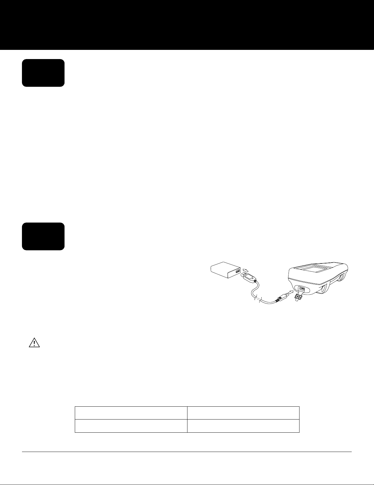
Charging the Battery Pack
A USB cable is included with the handheld to charge the
instrument battery pack and connect the instrument to a PC.
The battery pack can be charged from the AC power adapter,
directly from a computer USB connection or from an external,
portable USB battery pack (sold separately, see Accessories).
Plug the USB connector into the AC power adapter, computer
USB connector or external USB battery pack, then plug the
micro USB connector into the handheld (Figure 1).
WARNING: Charge the battery pack in an open area away from flammable materials, liquids, and surfaces.
Do not charge or handle a battery pack that is hot to the touch. Failure to follow the safety
warnings and precautions can result in personal injury and/or instrument damage not
covered under warranty. Read Rechargeable Lithium-Ion battery pack safety warnings and
precautions.
For the handheld to recognize that it is using AC power, you must start charging the handheld while it is turned on.
After the instrument recognizes it is being charged, it can be turned off to finish charging.
AC Charging DC Charging
9 hr 14 hr
Figure 1 Connecting the handheld to AC
power supply
4
Introduction
Page 5
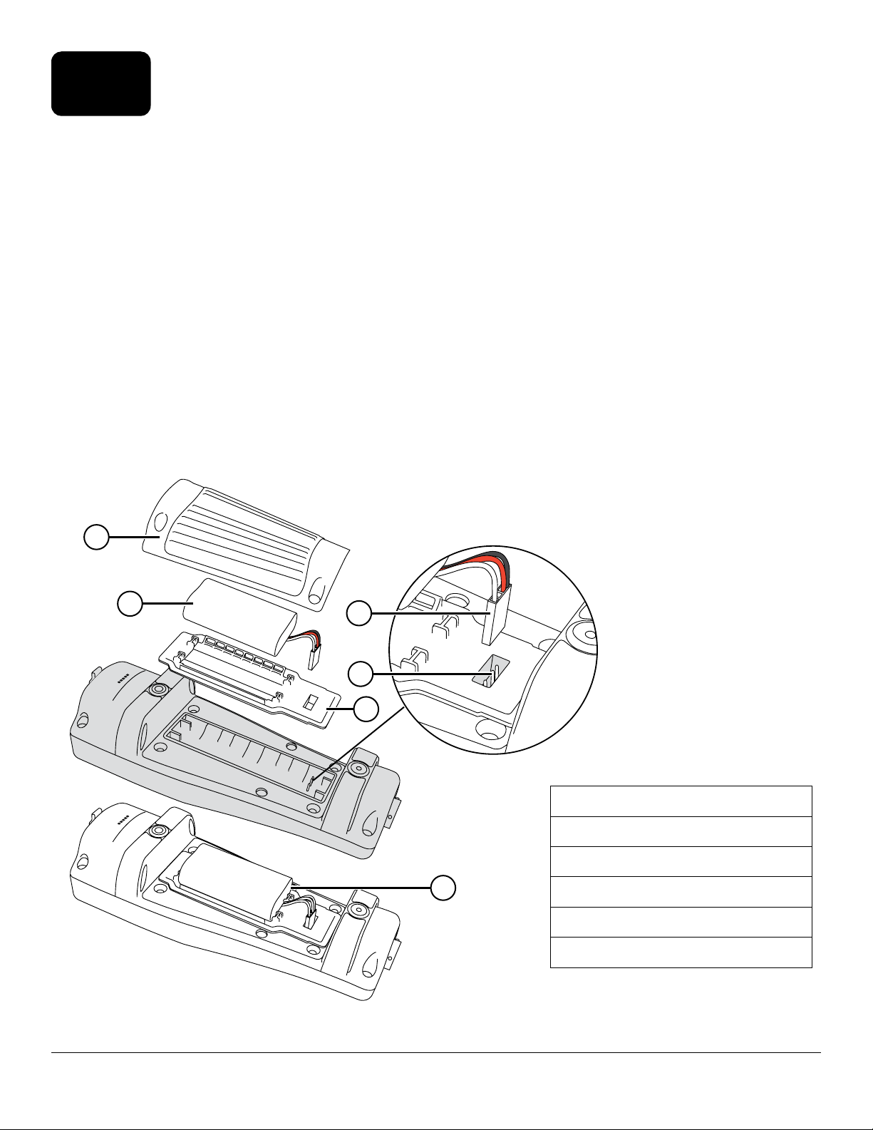
1.3
1. Remove the battery pack cover by unscrewing (counter-clockwise) the four screws with a flat or Phillips head
screwdriver (Figure 2). The retaining screws are captured into the battery pack cover and are not removable.
2. If replacing an existing battery pack, remove the Li-Ion battery pack and rubber battery pack cradle. With two
fingers, grasp the battery pack connector and pull the connector straight up to disconnect and remove. Properly
dispose of the old battery pack (See Battery Disposal).
3. Inspect the replacement battery pack and battery pack cradle for damage. Contact YSI technical support if there
is any damage.
4. Correctly align and seat the battery pack cradle and battery pack into the instrument.
5. Align the battery pack connector wire terminals with the three instrument pins, then connect the battery pack
to the instrument. Make sure that the three wire terminal connectors and three instrument pins are correctly
aligned before connecting the battery pack connector. Incorrect installation can damage the battery pack connectors or instrument pins.
6. Install the battery pack cover, then hand tighten the cover screws with a screwdriver. DO NOT use any power
tools. Make sure that the cover sealing surface is correctly aligned and free of any contamination or damage.
NOTICE: The battery cover does NOT need to make a compressed seal. Overtightening the cover screws can
Battery Replacement
damage the battery cover and the handheld.
1
2
3
4
5
1 Battery pack cover
2 Battery pack
3 Battery pack connector*
6
4 Instrument pin connectors
5 Battery pack cradle
Introduction
6 Battery pack cradle installed
*Color shown for reference
Figure 2 Battery replacement
5
Page 6
Connect the Handheld to the Cable
1.4
Assembly
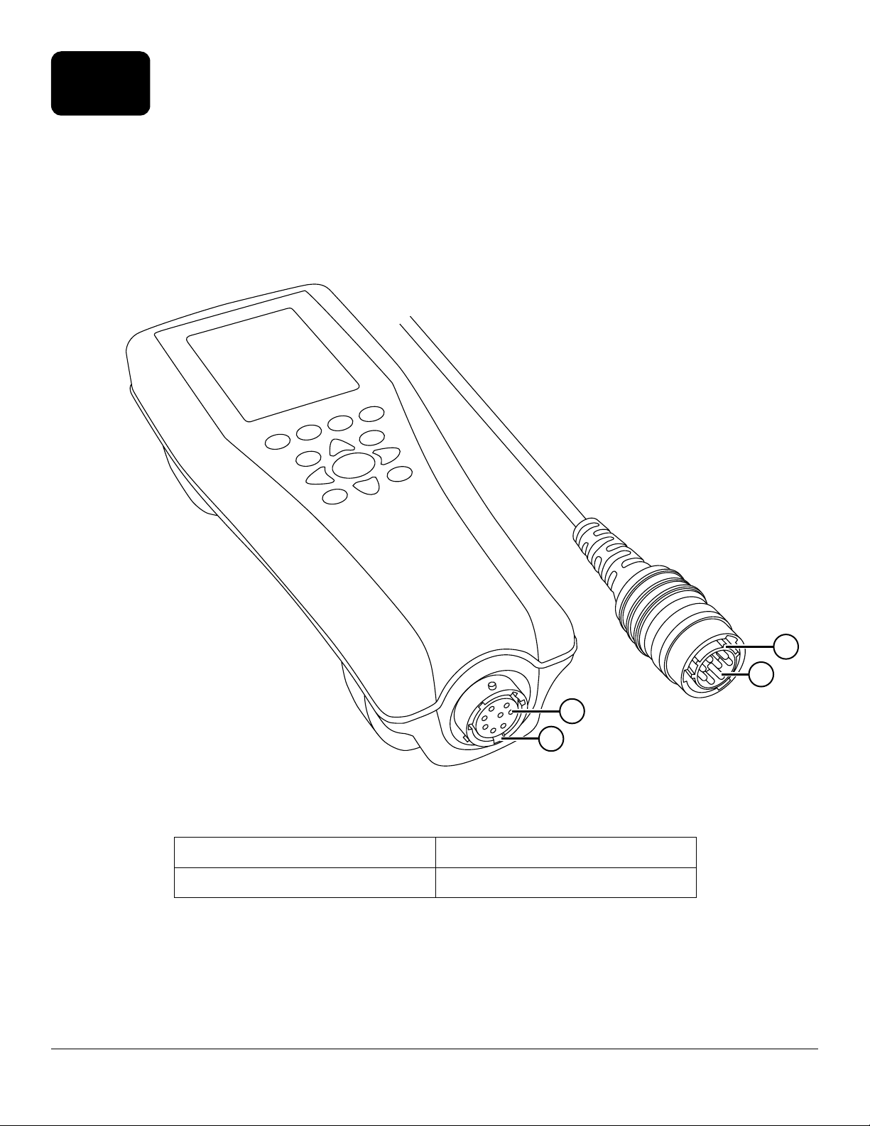
The cable connectors are keyed for positive mating and to prevent connector damage (Figure 3). The handheld retains
its IP-67 waterproof rating when the cable is disconnected. However, the connectors are not wet-mateable and should
be clean and dry before connecting.
Align the keys on the cable connector with the slots on the handheld connector. Push together firmly, then twist the
outer ring clockwise until it locks into place.
1
2
Figure 3 Keyed connectors
1 Handheld female connector 3 Keyed area of connector
2 Slotted area of connector 4 Cable male connector
3
4
6
Introduction
Page 7
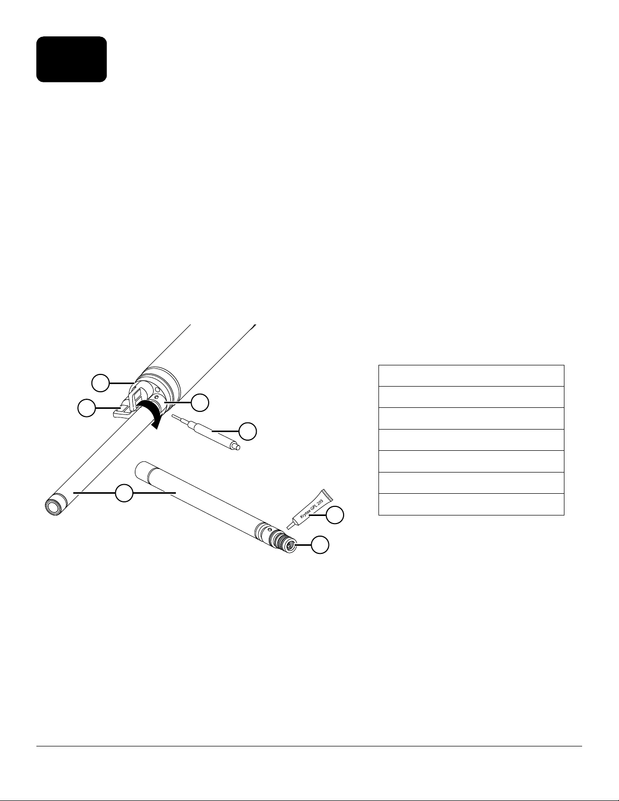
1.5
Probe assemblies like the ODO/CT, ODO/T, and ProOBOD feature integral sensors. These sensors cannot be removed
from the cable. Therefore, this section pertains only to the ProDSS 4-port cable.
Sensor Installation/Removal
ProDSS 4-port Cable
ProDSS 4-port cables feature user-replaceable sensors. The ports on the bulkhead are universal, meaning that you can
install any sensor into any port. A conductivity/temperature sensor must be installed for accurate measurement of all
parameters except turbidity and TSS.
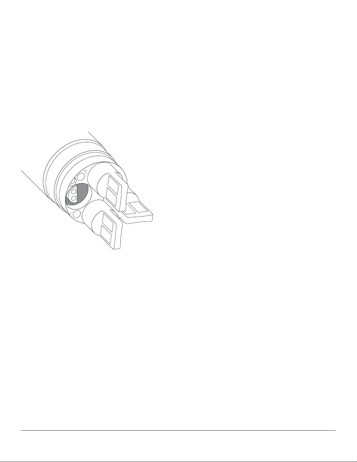
Bulkhead ports are numbered (Figure 4), so if multiple sensors of the same type are installed, the port number will be
added to the Run screen display to clarify the measurement value of each sensor.
NOTICE: The bulkhead ports and sensor connectors are not wet-mateable. Make sure that the sensor
connectors and bulkhead ports are clean and dry before sensor installation.
3
2
1
Figure 4 Sensor installation
4
5
6
7
1 Sensor
2 Port plug
3 Bulkhead
4 Sensor retaining nut
5 Sensor installation/removal tool
6 O-ring lubricant
7 Sensor port
Sensor Installation
1. Remove the port cover shipped with the 4-port cable. This cover can be kept to protect the bulkhead ports from
contamination during long-term storage.
2. Inspect each bulkhead port for contamination. If the port is dirty or wet, clean it with compressed air.
3. Apply a thin coat of o-ring lubricant to the sensor o-rings. Wipe off excess o-ring grease with a lint-free cloth.
4. Carefully align the sensor and bulkhead connectors by inserting the sensor into the port then gently rotating the
sensor until the connectors align. Once aligned, push the sensor toward the bulkhead until the sensor seats in
the port.
Introduction
7
Page 8
5. Carefully finger-tighten the retaining nut clockwise. If any resistance is felt, loosen the retaining nut completely
to prevent cross-threading.
6. Use the sensor installation/removal tool to tighten the retaining nut clockwise until snug, about a ¼ to ½
additional turn of the retaining nut. Be careful not to over-tighten the retaining nut.
NOTICE: Incorrect installation or over-tightening can cause damage to the sensor or bulkhead that is not
covered by the warranty.
Sensor Removal
To remove a sensor, insert the sensor installation/removal tool into the retaining nut, then rotate the retaining nut
counterclockwise to loosen. After the retaining nut has been completely unscrewed from the bulkhead, pull the sensor
straight out of the port and place it on a clean surface. Install a port plug if not reinstalling a sensor in the exposed port.
Exposure to water can cause damage or corrosion to the bulkhead connectors not covered by the warranty.
Port plugs
Port plugs and a tube of o-ring lubricant are included in the
maintenance kit that ships with all 4-port cables.
Installation
1. Apply a thin coat of o-ring lubricant to the o-rings
on the plug port.
2. Remove any excess lubricant from the o-rings and
port plug with a lint-free cloth.
3. Insert the port plug into the empty port and press
until firmly seated.
4. Finger-tighten the port plug clockwise to install. If
necessary, use the sensor installation tool to make
sure that the plug is fully seated into the port. The
Figure 5 Sensor port plugs and port
numbering (4-port cables)
o-rings will not be visible if a port plug is correctly
installed. Do not over-tighten the port plug.
NOTICE: Do not submerge the bulkhead without a
sensor or port plug installed in all ports.
Sensor Guard and Weight Installation
1. Carefully slide the sensor guard over the bulkhead and attached sensors/port plugs. Push the sensor guard
toward the bulkhead until the sensor guard threads align with the bulkhead threads.
2. Carefully hand-tighten the sensor guard clockwise. If any resistance is felt, loosen the sensor guard completely
to prevent cross-threading. Incorrect installation may cause damage to the sensor guard or bulkhead that is not
covered by the warranty.
8
Introduction
Page 9
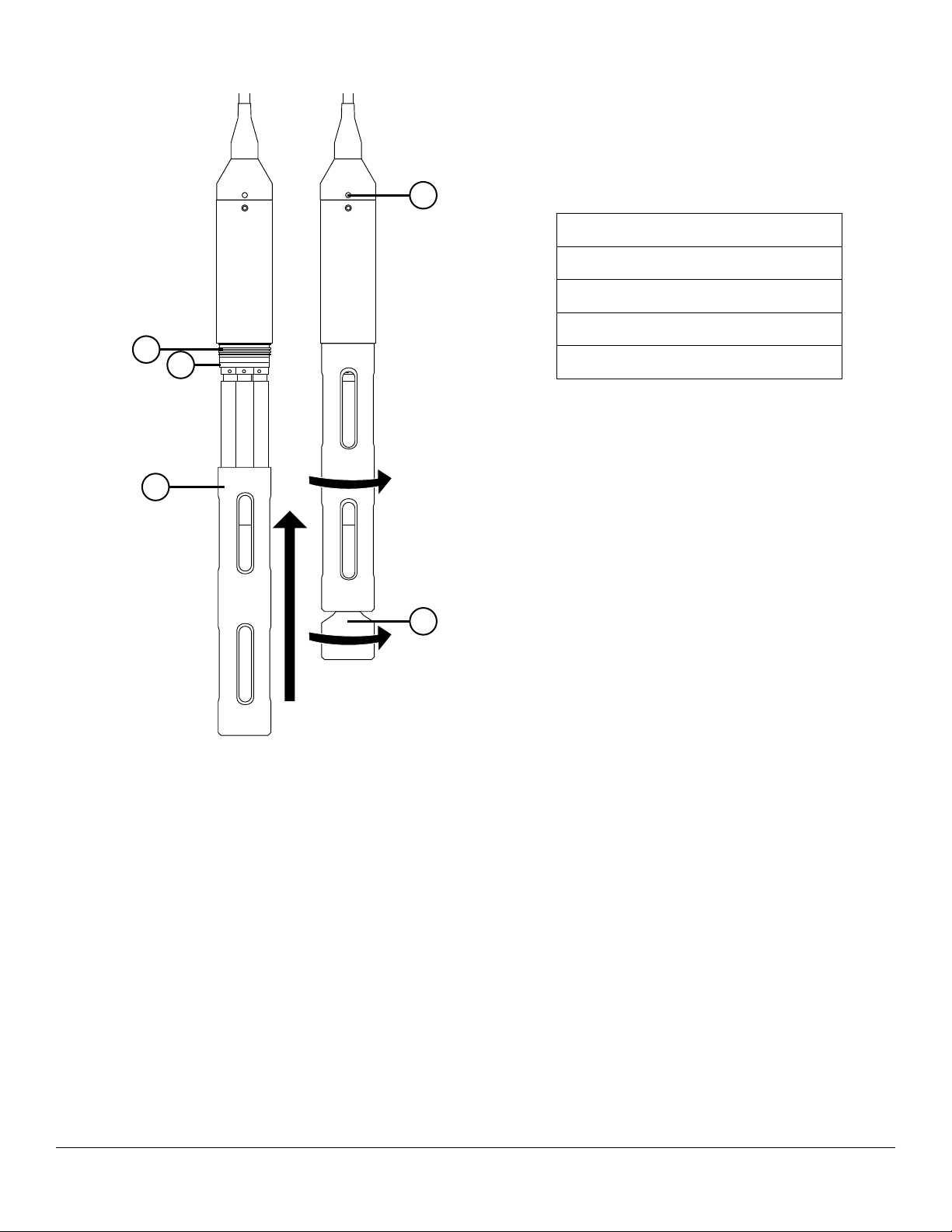
Sensor Guard and Weight Installation (continued)
1
2
3
4
1 Depth sensor (if equipped)
2 Bulkhead threads
3 Bulkhead
4 Sensor guard
5 Weight
5
Figure 6 Sensor guard and weight
installation on a 4-port cable assembly
Sensor Guard Weights
To help stabilize the sensors when profiling at deeper depths, a 1 lb. sensor guard weight is supplied with 4-port
assemblies 10 meters and longer. To attach the weight, carefully hand-tighten it clockwise on to the bottom of the
sensor guard (Figure 6). If any resistance is felt, loosen the sensor guard weight completely to prevent cross-threading.
The bottom of the weight is threaded so that additional weights can be added if needed. YSI recommends installing
no more than 5 lbs of weight on ProDIGITAL cables. See Accessories.
NOTE: Do not have any weights installed on the sensor guard when calibrating using the calibration cup.
Introduction
9
Page 10
2. Operation
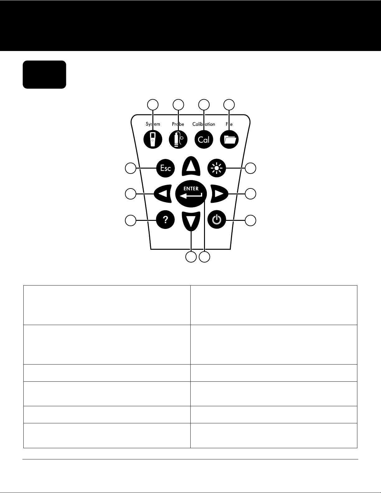
2.1
Keypad and Navigation
1
5 6
7
9 10
2 3 4
11 12
8
Figure 7 Keypad description
1 System: Opens the system menu. Use to adjust
system settings.
2 Probe: Opens the sensor menu. Use to setup sensors,
change the units shown, select the sensor averaging
mode, and turn on/off Auto Stable and GPS.
3 Calibrate: Opens the calibration menu. Use to
calibrate sensors or restore default calibration.
4 File: Opens the file menu. Use to view logged data
and calibration files, backup data to a USB stick, and
delete data.
5 Exit/Escape key: Exits to the Run screen. When in an
alpha/numeric entry screen, returns to previous menu.
6 Backlight: Turns the keypad backlight on or off for use
in low light conditions.
7 Left arrow key: Navigate left in an alpha/numeric
entry screen. Push to return to previous menu in all
screens except alpha/numeric entry. On the Run
screen, push to show graphical representations of the
displayed measurements.
8 Right arrow key: Navigate right in an alpha/
numeric entry screen. On the Run screen, push to
show graphical representations of the displayed
measurements. In the View Data screen, push to view
additional parameters in the data set.
9 Help: Shows context sensitive help.
10 ON/OFF: Turn on or turn off the instrument.
11 Up/Down arrow keys: Scroll through menus or enter
numbers and letters.
12 Enter key: Push to confirm selections. On the Run
screen, push to log a single data point or start
continuous data logging.
10
Operation
Page 11
2.2
Push the On/Off ( ) key to turn on the handheld. If the handheld does not turn on, make sure that the battery is
charged. Push and hold the
Startup
key for 1.5 seconds to turn the handheld off.
2.3
The handheld contains menus to change user-defined options, functions, and parameters. Use the arrow keys
and ) to highlight different options within menus and sub-menus, then push the Enter (
(
option. Push the left arrow ( ) key to return to the previous menu.
Push the Exit/Escape (
push the
functions appear as a circle only ( ) or an empty box ( ).
ENTER
Navigation
ENTER
) key to select the
Esc
) key to return to the Run screen. To enable or disable an option, highlight the option, then
key. Enabled functions appear as a circle with a dot ( ) or a box with a check mark ( ). Disabled
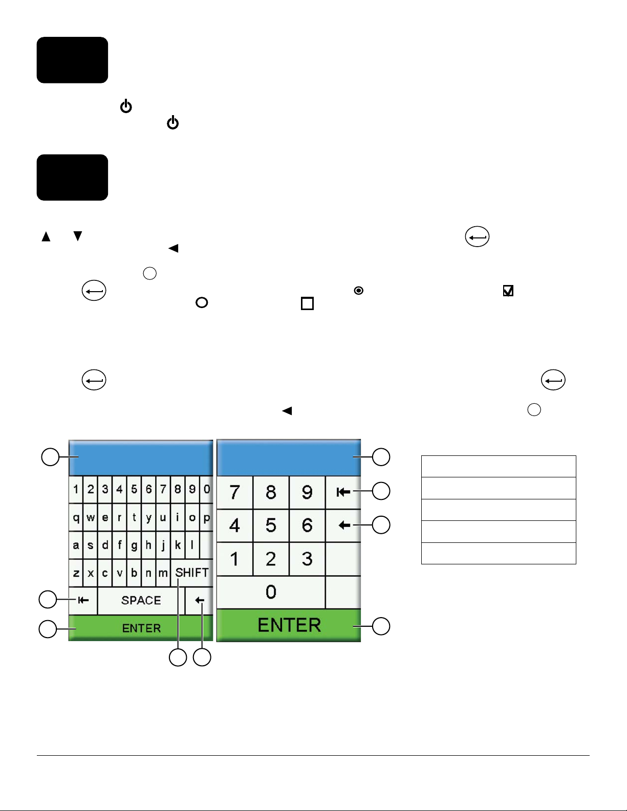
Alpha/Numeric Entry
When required, an alpha/numeric entry screen will be shown. Use the arrow keys to highlight a specific character and
push the
to save the entry (Figure 8).
1
ENTER
key to select it for entry. When finished entering information, highlight ENTER, then push the
NOTE: When in an alpha/numeric screen, the
cancel and return to the previous menu.
key is for alpha/numeric navigation only. Push the
1
1 User entry field
Esc
key to
ENTER
key
2
4
Operation
3
5
Figure 8 Alpha/numeric and numeric entry screens
2
3
2 Delete entire entry
3 Backspace
4 Enter (highlighted selection)
5 Upper/lowercase
4
11
Page 12
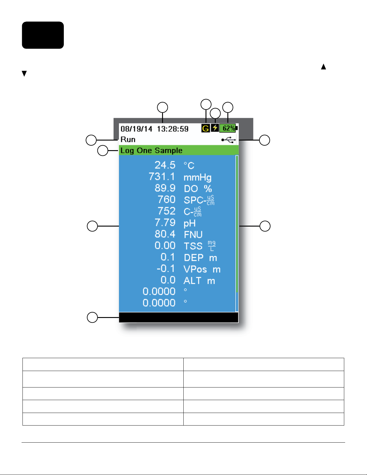
2.4
The main display (Run screen) shows the current measurements and units as defined in the Sensor Display menu. If
more measurements are selected than can be displayed on the Run screen, a scroll bar will be shown. Use the and
arrow keys to view the additional measurements (Figure 9).
The message area shows status messages, error messages, and information about selected functions.
Main Display Description
1
5
7
8
2
4
3
6
9
10
Figure 9 Main display example
1 Date/Time 6 USB/PC connection indicator
2 GPS signal indicator 7 Log or sampling (update measurements) prompt on
Run screen (single or continuous)
3 Battery charging indicator 8 Displayed measurements
4 Battery charge % 9 Scroll bar
5 Current screen/menu 10 Message area
12
Operation
Page 13
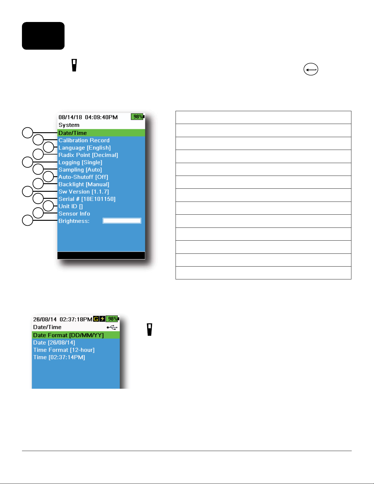
2.5
System Menu
Push the System ( ) key to view and adjust instrument settings. Highlight a sub-menu then push the
the sub-menu options (Figure 10).
Pre-defined or user-selected options are noted within brackets ( [ ] ).
1 Set the Date and Time
1
2
3
4
5
6
7
8
9
10
11
12
13
2 Change the user-defined Calibration Options
3 Change the instrument Language settings
4 Change the Radix Point
5 Change the Logging options
6 Change the Sampling options
7 Set the handheld Auto-Shutoff time
8 Set the Backlight mode
9 View the Software Version
10 View the handheld Serial Number
ENTER
key to view
Figure 10 System menu
Figure 11 Date/Time
11 View and adjust the Unit ID
12 View the Sensor specific information
13 Adjust the display Brightness
Date/Time
→ Date/Time
For accurate logging and calibration data, correctly set the date and time
options (Figure 11). Select any of the following options to set the Date/
Time.
Date/Time options:
• Set YY/MM/DD, MM/DD/YY, DD/MM/YY or YY/DD/MM date format
• Set the correct date
• Select 12 or 24 hour time format
• Set the correct time
Operation
13
Page 14
Calibration Record
Detailed sensor calibration information is stored for later review. The instrument’s internal memory can save up to 400
individual calibration records. After 400 records, the instrument will overwrite previously stored calibration records,
starting with the oldest. To prevent the permanent loss of calibration records, periodically download the calibration
files to a computer using the KorDSS software.
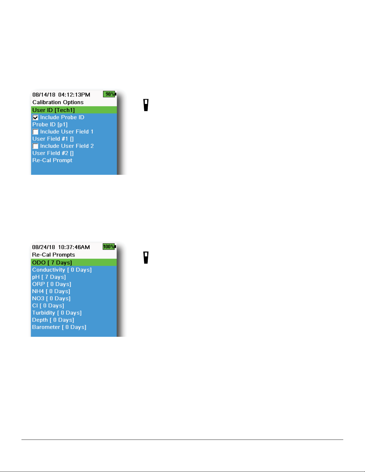
Calibration Options
→ Calibration Record → Options
User ID, Probe ID, or User Field #1 or 2 can be user-defined for positive
calibration file identification of:
• The person calibrating the instrument
• The sensor/cable serial number used during calibration (or other,
user-defined Probe ID)
• Other user-specific identification (User Field #1 and #2) (Figure 12)
Figure 12 Calibration Options
Figure 13 Re-Cal Prompts
NOTE: User Field can be used to describe the condition of the
probe. For example, new sensor or new ODO cap.
Re-Cal Prompts
→ Calibration Record → Options → Re-Cal Prompts
Re-Cal Prompts provide a reminder to recalibrate a probe in the
user-defined number of days (Figure 13). Select the desired sensor Re-Cal
prompt, then enter the desired number of days before the Re-Cal prompt
occurs. This reminder will be provided when the instrument is powered
on and will reoccur every day until the sensor is re-calibrated.
Set the sensor value to zero (0) days (default) to turn off Re-Cal prompts.
14
Operation
Page 15
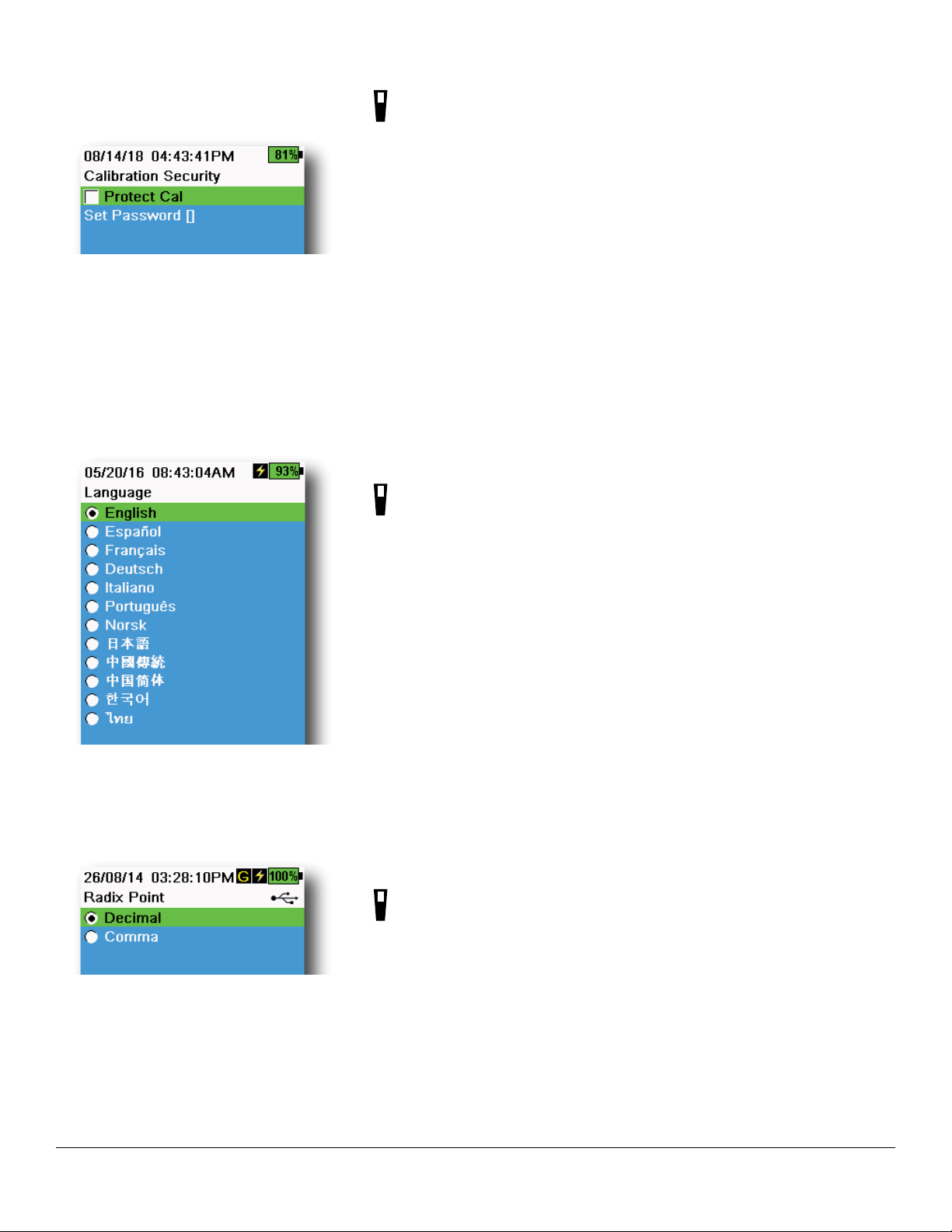
Figure 14 Calibration Security
Calibration Security
→ Calibration Record → Security
The Calibration menu can be password protected to prevent accidental
or unauthorized sensor calibration (Figure 14).
1. From the Calibration Record menu, select Security, then enter the
default password “ysi123”.
2. Select Set Password [ ] and change the default password.
3. Select the Protect Cal check box to password protect the
Calibration menu.
NOTE: Write down and keep the password in a safe place. Contact
YSI Technical Support if you lose the password (Technical
support).
Language
→ Language
Figure 15 Language
Figure 16 Radix Point
The instrument is shipped with English enabled. If a different language
is desired and selected, the handheld will take approximately 10 to 20
seconds to enable the new language (during the first installation only).
Optional languages:
• Spanish
• French
• German
• Italian
• Portuguese
• Norwegian
• Japanese
• Simplified Chinese
• Traditional Chinese
• Korean
• Thai
Radix Point
→ Radix Point
The radix point can be changed to display a comma or a decimal in
numeric displays (e.g. 1.00 becomes 1,00 when Comma is selected)
(Figure 16).
Operation
15
Page 16
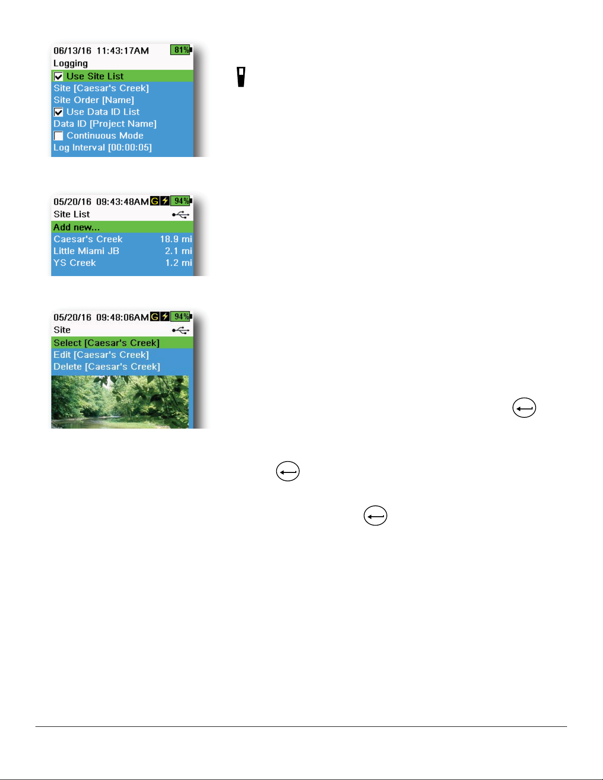
Figure 17 Logging
Figure 18 Site List
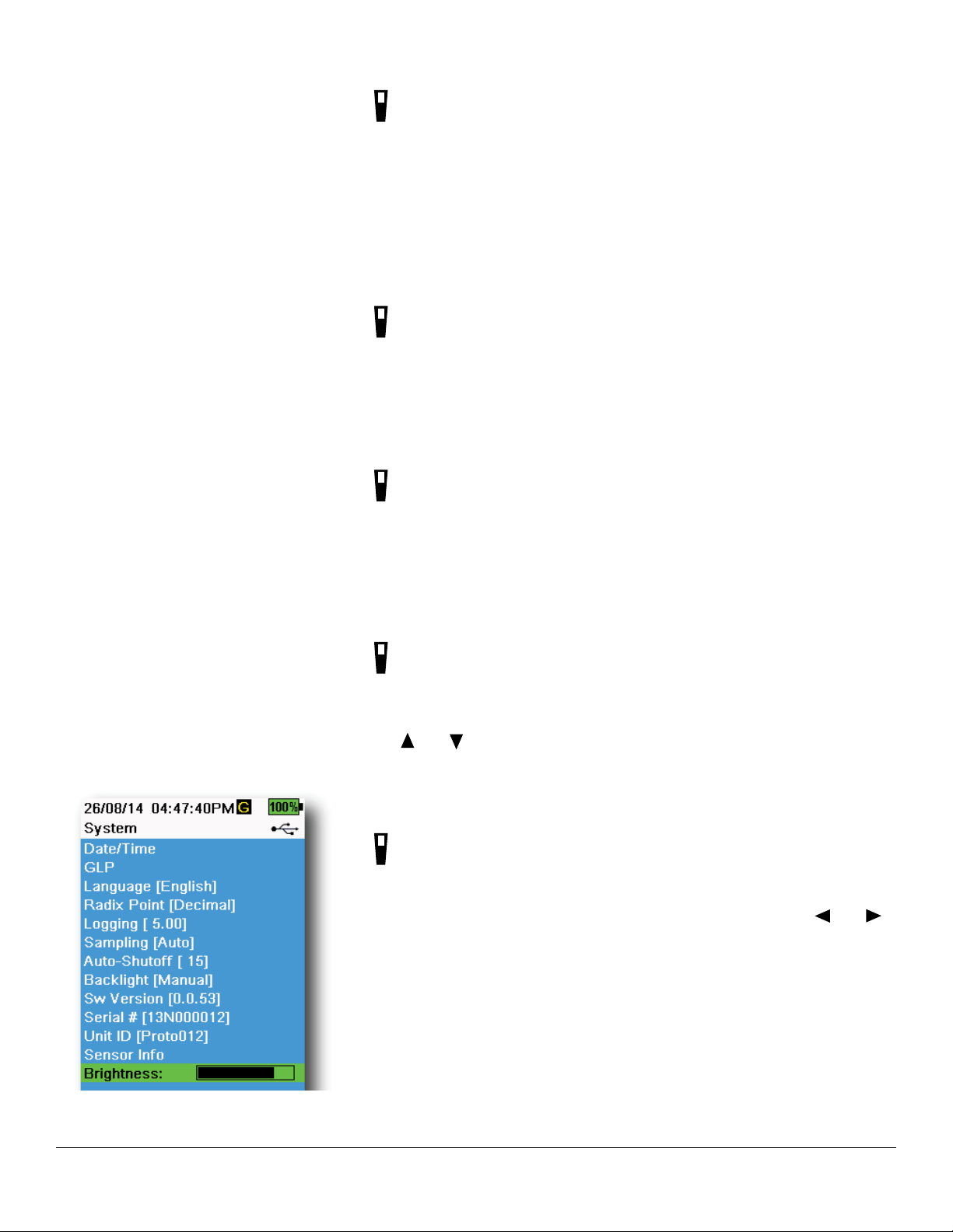
Logging
→ Logging
The handheld can add a user-defined Site and/or Data ID to a data record
if these functions are enabled under the Logging menu. A check mark in
the box next to these features indicates they are enabled (Figure 17).
After selecting Site [ ] or Data ID [ ], the Site List or Data ID List will be
shown (Figure 18). New entries can be created by choosing Add new...
If the handheld has a GPS signal, the current GPS coordinates will be
auto-populated when creating a new site. If the handheld does not have a
built-in GPS, the coordinates and altitude can be entered manually.
Sites can be listed in order of Name (i.e. alphanumeric order) or Distance
from the current position (Figure 18).
Choose an entry from the Site List or Data ID List to Select, Edit, or
Delete (Figure 19). When selected, data recorded will be tagged with the
specific site and/or data ID.
NOTE: The Manage Sites menu in KorDSS Software can be used to
send a picture of the Site to the instrument.
Figure 19 Site
Continuous Mode ( Interval logging): Select the Continuous Mode check
box and enter the user-defined Log Interval (in hours:minutes:seconds)
to log samples continuously at the specified time interval. The Run screen
will display Start Logging... when in Continuous Mode. Press
ENTER
to
begin logging.
One sample logging: Clear the Continuous Mode check box. The
Run screen will display Log One Sample. A sample will be logged each
time the
ENTER
key is pushed when in the Run screen.
NOTE: An option to change Site and/or Data ID (if enabled)
appears once
ENTER
is pressed to begin logging.
16
Operation
Page 17
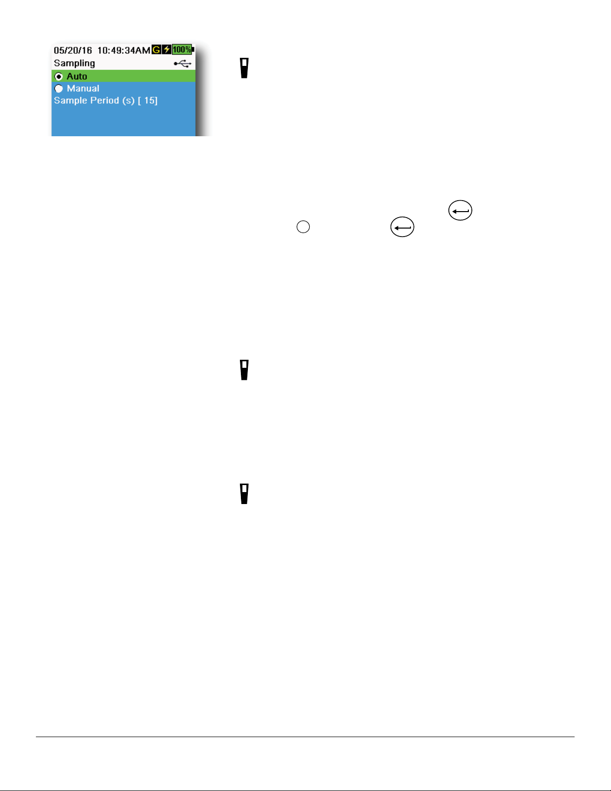
Figure 20 Sampling
Sampling
→ Sampling
Auto sampling mode continuously updates measurements on the display
(Figure 20).
When in Manual mode, the instrument will take measurements for the duration of the user-defined Sample Period (in seconds) then “lock” or hold
the readings on the display. The default sample period is 50 seconds, and
can be adjusted from 15 to 60 seconds. Manual mode helps conserve
battery power.
Once the measurements are locked, push the
data, or the
Esc
key and then the
ENTER
key to take a new measurement.
ENTER
key to log the held
NOTE: When both Continuous Logging Mode and Manual
Sampling mode are enabled, the handheld will power the
sensors on and take measurements for 15 seconds before
logging a data set.
Auto-Shutoff
→ Auto-Shutoff
To conserve battery power, auto-shutoff powers off the instrument after
a user-defined time period (in minutes). The auto-shutoff time can be
adjusted from 1 to 255 minutes. Set to 0 (zero) to disable Auto-Shutoff.
Backlight
Operation
→ Backlight
In Automatic mode, the instrument display will dim 60 seconds after the
last key was pushed. Once any key is pushed, the instrument display will
return to the user-defined brightness setting and the keypad backlight
will turn on. The screen will dim and the keypad backlight will turn off
after another 60 seconds of inactivity.
In manual mode, the instrument display remains at the user-defined
brightness and the keypad backlight is turned on and off by the Backlight
key. Setting the backlight to manual mode is recommended for bright
conditions.
17
Page 18
Software (Sw) Version
→ Sw Version
Sw Version shows the instrument’s software version number. The latest
instrument software and update instructions are available at YSI.com.
Instrument software can be updated through the KorDSS Software under
the Instrument and Sensors tab.
Serial #
→ Serial #
Serial # shows the serial number of the handheld instrument. Note the
serial number when contacting YSI support.
Unit ID
→ Unit ID
Users can set a custom Unit ID. The Unit ID identifies the instrument in
KorDSS Software.
Sensor Info
→ Sensor Info
Sensor info shows measurement data, and hardware/software information
for each component of the system: instrument, sensor, and bulkhead. Use
the and arrow keys to scroll through the components.
Brightness
→ Brightness
The screen brightness can be adjusted to accommodate lighting
conditions and to conserve battery power (Figure 21). Use the and
arrow keys to adjust the screen brightness.
Figure 21 Display Brightness
18
Operation
Page 19
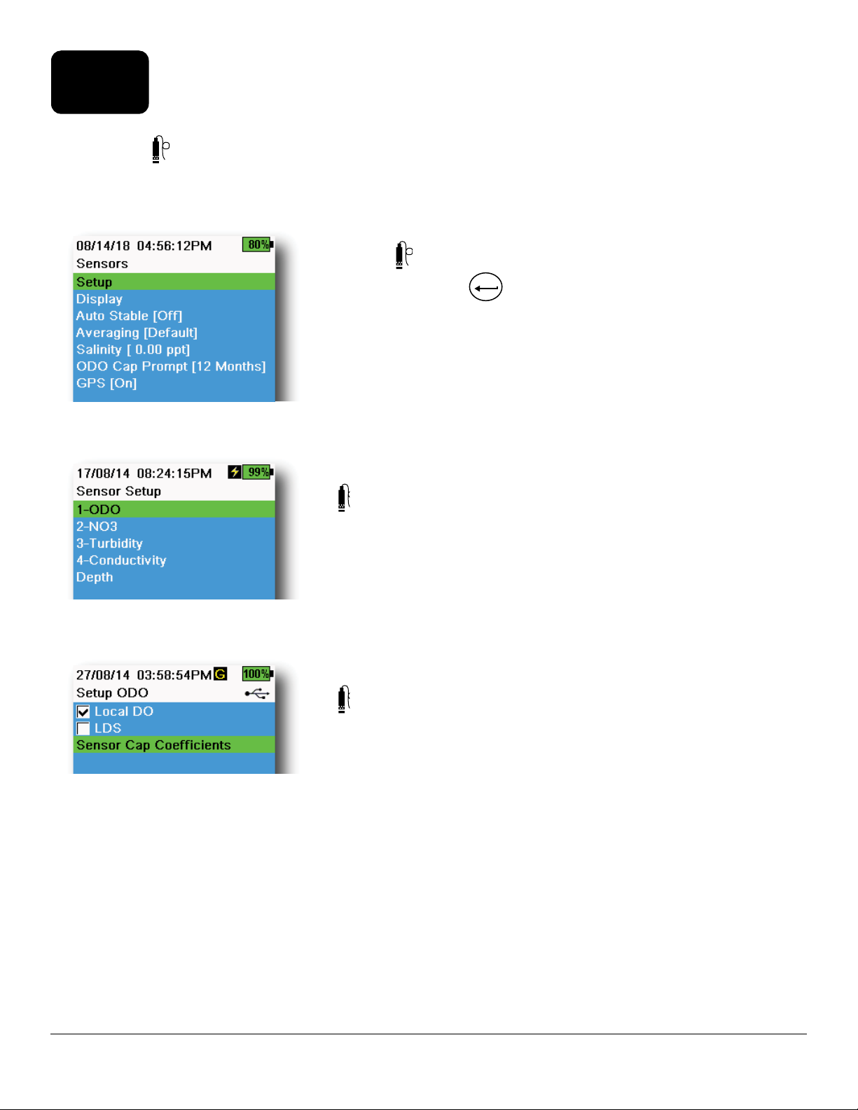
2.6
Sensor Menu
Use the Probe (
ment units displayed on the Run screen, set Auto Stable parameters, change the sensor averaging mode, and if
equipped, turn on/off GPS.
Figure 22 Probe (Sensor) menu
) key to access the Sensor menu and change sensor settings (if applicable), enable the measure-
Push the key to access the sensor menu (Figure 22). Highlight a sub-
menu then push the
Pre-defined or user-selected sensor settings are noted within brackets ([]).
ENTER
key to view sub-menu options.
Sensor Setup
→ Setup
The Sensor Setup menu will show all sensors connected to the instrument
(Figure 23). If a sensor is connected but is not listed on the Sensor Setup
menu (<None> displayed), check the sensor and cable connections.
Figure 23 Sensor Setup
Figure 24 Setup ODO
Setup ODO
→ Setup → ODO
Local DO: Enable or disable localized DO% measurements. When
enabled, the calibration value is set to 100% regardless of altitude or
barometric pressure. When enabled, an L will be shown next to DO% on
the run screen. DO mg/L measurements are unaffected when Local DO is
enabled (Figure 24).
LDS: Last Digit Supression (LDS) rounds the DO value to the nearest
tenth, e.g. 8.27 mg/L becomes 8.3 mg/L.
Sensor Cap Coefficients: The sensor cap coefficients must be updated
after sensor cap replacement. Update the sensor cap coefficients using
the coefficient sheet provided with the new sensor cap. Once updated,
the coefficients are saved to the ODO sensor and do not need to be
re-entered.
NOTE: The coefficients stay with the sensor even when used with
different handheld meters.
Operation
19
Page 20
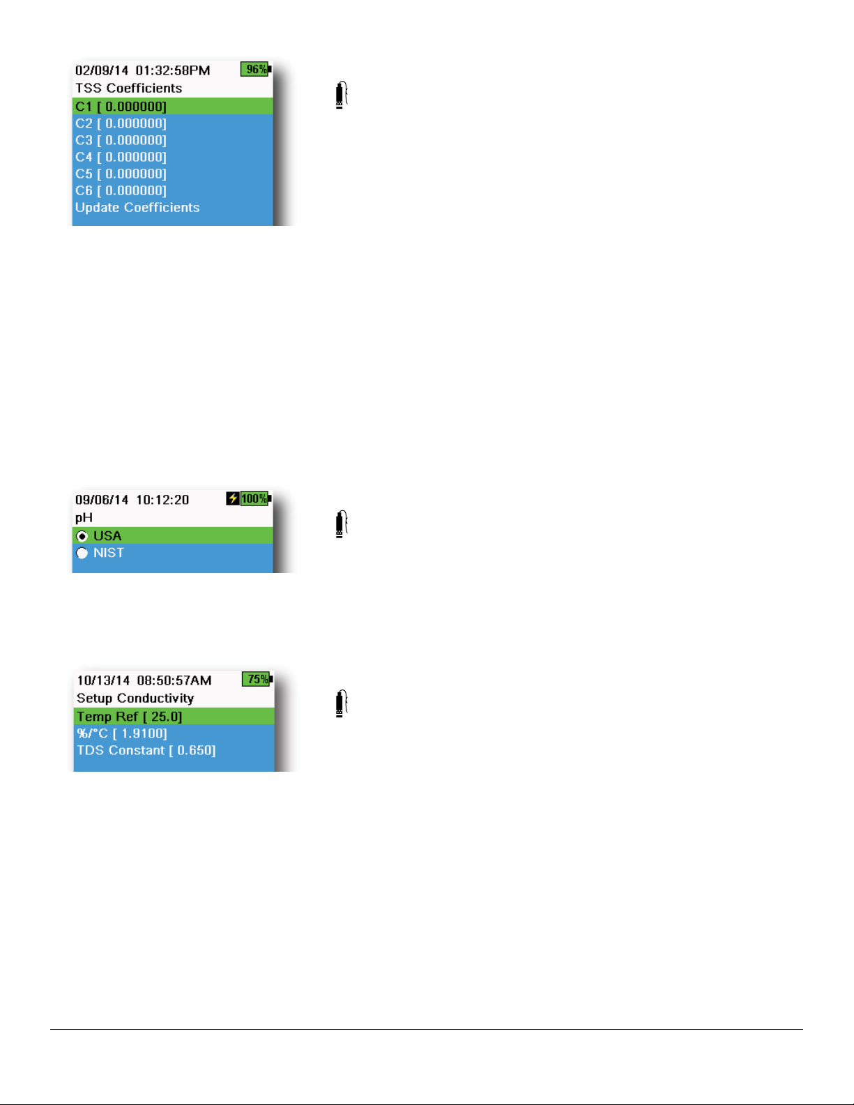
Figure 25 TSS coefficients
Setup Turbidity
→ Setup → Turbidity
TSS Coefficients: Total Suspended Solids (TSS) can be measured if
correlation coefficients are calculated in KorDSS.
To obtain these coefficients, collect turbidity data at the sampling site with
corresponding grab samples. Analyze the samples in a lab to determine
a true TSS measurement (mg/L). At least 2 and up to 6 value pairs of
turbidity and TSS measurements can be used.
Correlation data must be collected for each unique sampling site, as this
correlation is site-specific.
In KorDSS Software, enter the field-obtained turbidity measurements and
the corresponding lab-obtained TSS measurements in the Instrument and
Sensors menu. Coefficients can then calculated with KorDSS and sent to
the sensor.
NOTE: Although correlation coefficients can be entered directly
into the handheld (Figure 25), only KorDSS Software can
calculate the coefficients.
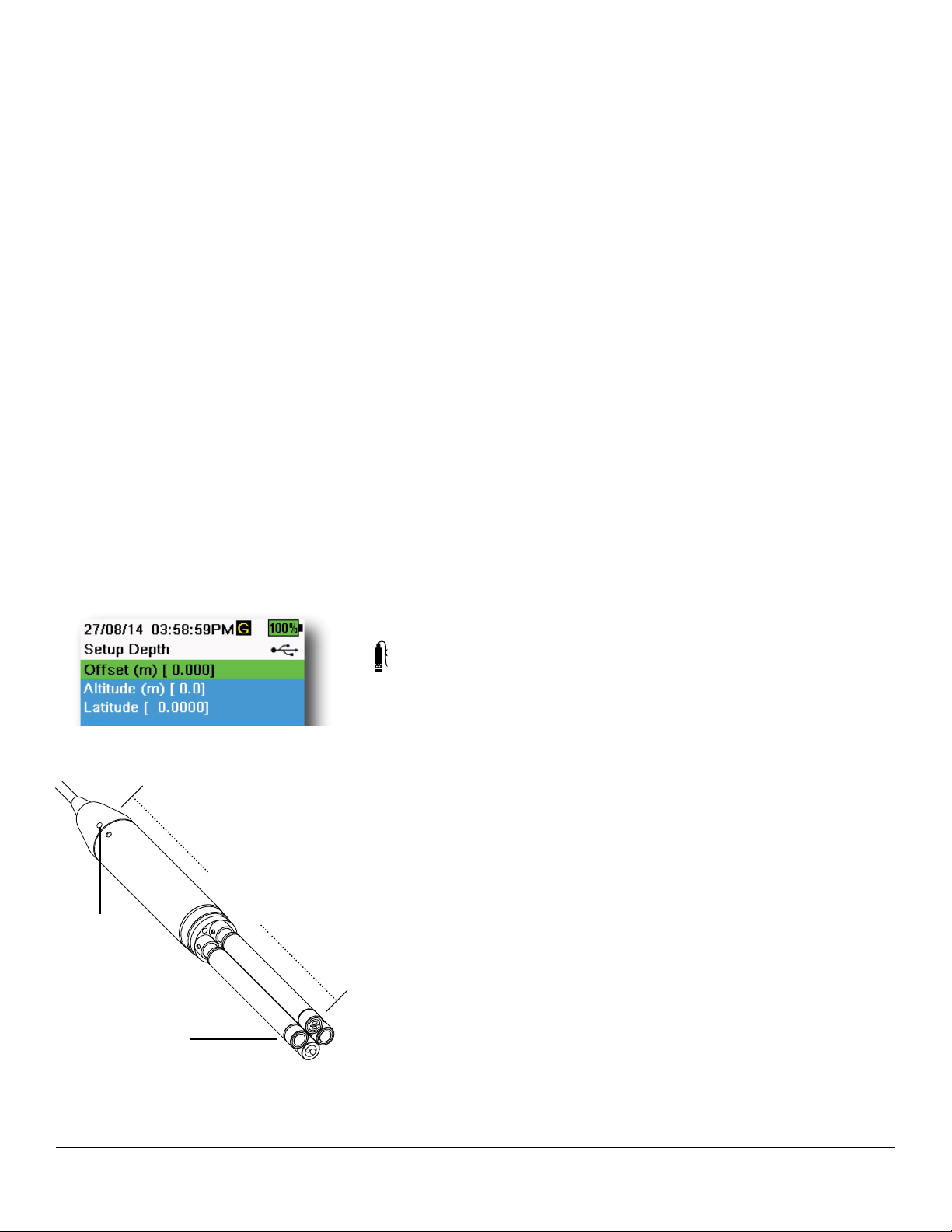
Figure 26 Setup pH
Figure 27 Setup Conductivity
Setup pH
→ Setup → pH
Select USA auto-buffer recognition (4.00, 7.00, and 10.00) or NIST autobuffer recognition (4.01, 6.86, and 9.18) (Figure 26). Calibration values are
automatically compensated for temperature for both buffer sets.
Setup Conductivity
→ Setup → Conductivity
Temp Ref: Reference temperature is used to calculate temperature
compensated specific conductance. All specific conductance values are
compensated to the Temp Ref temperature. The default value is 25°C
(Figure 27). Enter a new value between 15.00°C and 25.00°C.
%/°C (Percent per degree Celsius): The temperature coefficient is used to
calculate temperature compensated specific conductance. The default is
1.91% based on KCl standards. Enter a new value between 0 and 4%.
20
TDS Constant: This is a multiplier used to calculate an estimated Total
Dissolved Solids (TDS) value from conductivity. The multiplier is used to
convert specific conductance in mS/cm to TDS in g/L. The default value is
0.65. Enter a new value between 0 and 0.99.
Operation
Page 21
Setup Conductivity (continued)
The TDS multiplier is highly dependent on the nature of the ionic species
present in the water sample. To be assured of moderate accuracy for
the conversion, you must determine a multiplier for the water at your
sampling site. Use the following procedure to determine the multiplier for
a specific sample:
1. Determine the specific conductance of a water sample from the
site.
2. Filter a portion of water from the site.
3. Carefully measure a volume of the filtered water. Completely
evaporate to yield a dry solid.
4. Accurately weigh the remaining solid.
5. Divide the weight of the solid (in grams) by the volume of water
used (in liters) to yield the TDS value in g/L for the site.
6. Divide the TDS value in g/L by the specific conductance of the
water in mS/cm to yield the conversion multiplier.
NOTE: If the nature of the ionic species at the site changes
between sampling studies, the TDS values will be in
error. TDS cannot be calculated accurately from specific
conductance unless the make-up of the chemical species in
the water remains constant.
Figure 28 Setup Depth
0.272 m
Depth
Sensor
WQ
Sensors
Figure 29 Distance of depth sensor to
WQ sensors on 4-port cable
Setup Depth
→ Setup → Depth
Cable assemblies with a depth sensor in the bulkhead can measure virtual
vented depth. The virtual vented depth measurement allows for real time
compensation for atmospheric pressure using the handheld’s barometer.
Depth offset: Depth offset can be used if referencing water elevation
against a known value. If a depth offset is entered (in meters), the output
value will shift by the value of the offset (Figure 28).
A common offset entered by the user is the depth sensor location relative
to the rest of the WQ sensors. This value is 0.272 m on the 4-port cable
(Figure 29).
Altitude/Latitude: To compensate for atmospheric pressure based on
elevation and gravitational pull, enter the local altitude in meters relative
to sea level and latitude in degrees where the instrument is sampling.
Latitude effect: Varying latitudes can cause up to a 200 mm change in
depth from equator to pole.
Altitude effect: A 100 m change in altitutde causes a 1.08 mm of change
to the depth readings.
Operation
21
Page 22
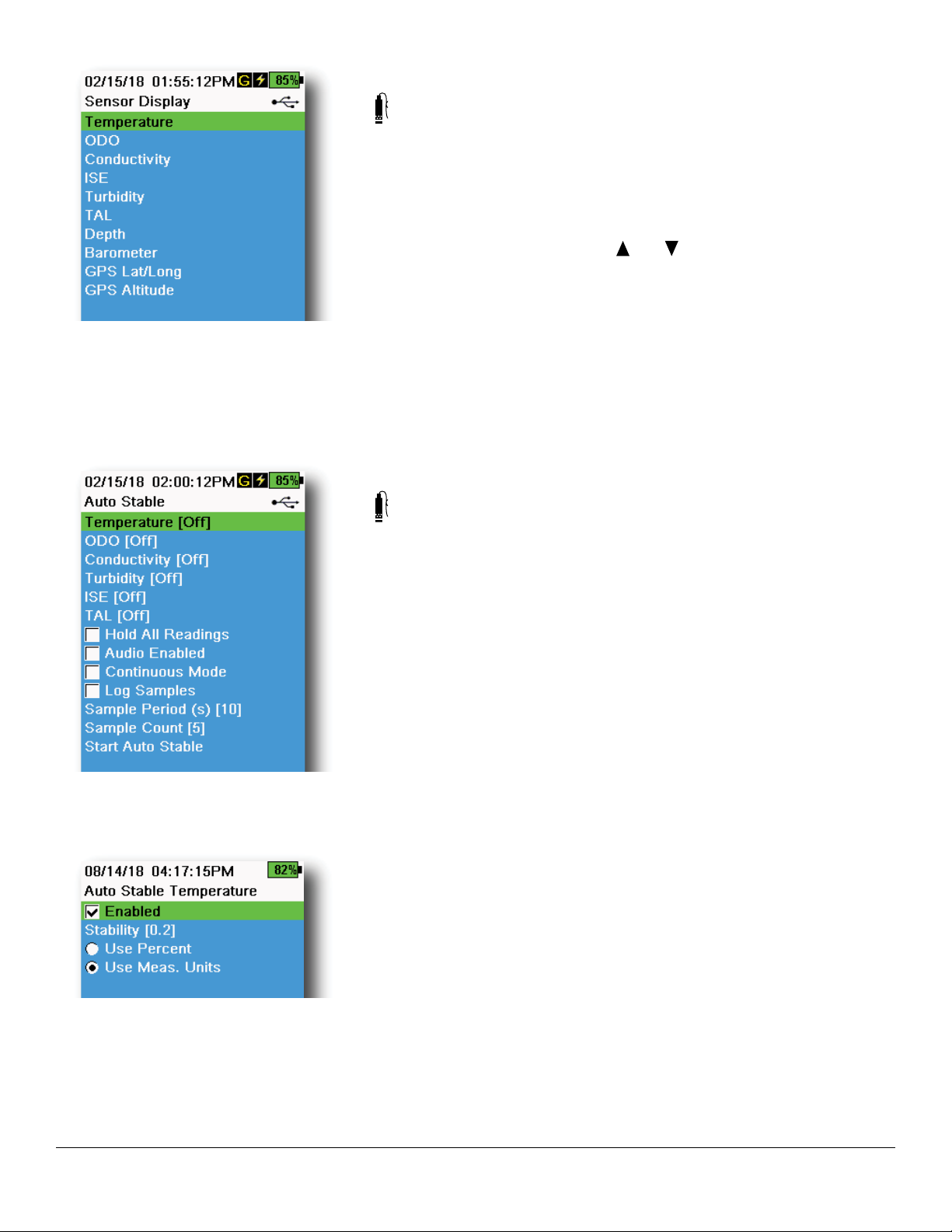
Figure 30 Sensor Display
A
S
A
S
A
S
Sensor Display
→ Display (Figure 30)
The Sensor Display menu determines the parameters and units that
are shown on the Run screen (Figure 9). The Run screen will only show
measurements for sensors that are attached to the cable bulkhead.
If more measurements are selected than can be displayed on one screen,
a scroll bar will be shown. Use the and keys to scroll through the
measurements.
NOTE: For depth profiling, enable Vertical Position under Depth
Display to view the real-time position of the depth sensor
in the water column. This is helpful in profiling applications
to ensure the depth sensor is lowered to the desired depth
without waiting for the depth data to stabilize.
Auto Stable
→ Auto Stable
Figure 31 Auto Stable
Figure 32 Auto Stable stability
threshold
Auto Stable indicates when a measurement is stable. Sensors with Auto
Stable enabled will have
flash beside the measurement on the Run
screen.
will flash green when the measurement is stable.
Select a sensor to enable or disable Auto Stable (Figure 31). Then set the
stability threshold parameters.
The Auto Stable stability threshold can be set by percent of measurement
or in the units of measurement selected in the Sensor Display menu.
Enter the stability value, then select Use Percent or Use Meas. Units
(Figure 32).
This threshold is used to compare the last reading with the previous. The
smaller the number entered in % or units, the longer it will take for the
instrument to reach the auto stable criteria.
Example: For temperature in °C, if Measurement Units threshold is set
to 0.2 and the temperature reading changes by more than 0.2
degrees,
will continue to be red until the reading does not
change by more than 0.2°C over the defined sample period
and sample count.
Hold All Readings: After all sensors have reached their stability criteria,
the measurements will be held or ‘locked’ on the display. If disabled, the
sensor measurements will continue to change in real time.
Audio Enabled: An audio alert will sound when stability is reached.
22
Operation
Page 23
Auto Stable (continued)
Continuous Mode: The handheld will continuously check sensor values
against the stability criteria even after the sample period and sample
count have been met.
Log Samples: Logs the sample/s defined by the Sample Period to
memory.
Sample Period: Time interval between samples that are used to
determine stability. Set the interval in seconds (1 to 900).
Sample Count: Number of consecutive samples required for stability
(1 to 10).
Select Start Auto Stable to enable.
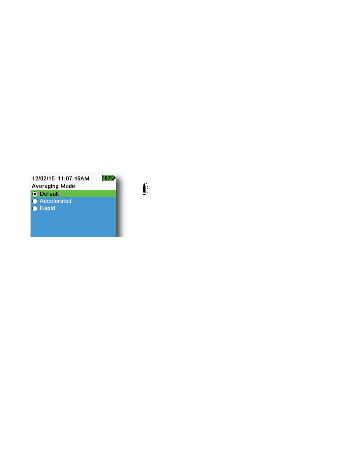
Averaging
→ Averaging (Figure 33)
Figure 33 Averaging
The averaging mode determines how the handheld will filter data. A
smaller time frame for the rolling average window allows changes in
the sensor’s measurements to be more quickly observed, while a larger
rolling window provides more stable measurement readings and a
smooth result. Each averaging mode will decrease the time span of the
rolling window if a large change in the sensor measurement is detected,
allowing the handheld to adapt when an event occurs.
The Default mode provides optimum averaging for all sensors. This
mode has up to 40 seconds of averaging on the sensors to curb spikes
and outliers, resulting in more stable data.
In Accelerated mode, changes in sensor measurements are more quickly
observed than default (approximately 10 seconds of averaging). This
mode is recommended when the sensors are moving through the water,
such as during profiling studies and most spot sampling applications.
NOTE: For profiling applications, enable Vertical Position under
Depth Display to view unfiltered depth measurements. This
helps to ensure the depth sensor is lowered to the desired
depth without waiting for the averaged measurement.
In Rapid mode, sensor response is very fast (approximately 2 seconds of
averaging), but the instrument will never settle on a single steady number.
This mode is recommended when the sensors are moving quickly
through the water, such as rapid profiling and towed applications.
Operation
23
Page 24
Salinity
→ Salinity
Salinity is determined by calculations derived from the conductivity and
temperature sensors.
When a conductivity sensor is installed, the instrument will automatically
use the salinity measurement for DO and “As Measured” will be
displayed. If no conductivity sensor is installed (e.g. ODO/T cable
assembly used), the salinity value will be user-selectable.
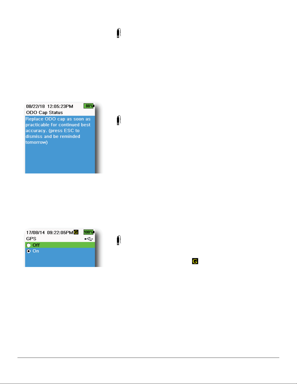
ODO Cap Prompt
→ ODO Cap Prompt
The handheld can remind users when it is time to replace the ODO Cap
based on a user-defined interval (Figure 34). To set the reminder, select
ODO Cap Prompt and input a number in months. YSI recommends
enabling this setting to match the warranty period of the ODO Cap:
Figure 34 ODO Cap Status
Figure 35 GPS
• ProDSS ODO Sensor Cap [SKU: 626890] = 12 months
• ODO Extended Warranty Sensor Cap [SKU: 627180] = 24 months
The handheld will automatically recognize the last time the ODO Sensor
Cap coefficients were updated and alert the user when the Cap is due
for replacement. To disable the prompt, simply enter 0 for the number of
months.
GPS (Optional)
→ GPS
Some handhelds feature a built-in GPS. GPS turns the handheld Global
Positioning System On or Off. The
is received (Figure 35).
When enabled, the GPS coordinates will be saved with the Calibration
Record and logged data. Note that the battery will drain more rapidly
when GPS is enabled than when it is not enabled.
symbol is shown when a GPS signal
24
NOTE: GPS data will be most accurate when there is a clear line of sight
to satellites. It may be difficult for the handheld to receive a good
GPS signal when under canopy or indoors.
Operation
Page 25

2.7
Calibration Menu
Push the Calibrate (
key to view sub-menu options. Pre-defined or user-selected parameters are noted within brackets ( [ ] ). Refer to the
Calibration section for sensor specific calibration procedures.
NOTE: User ID, Probe ID, and User Field #1 and #2 can be enabled in the Calibration Settings under the
System menu.
Cal
) key to access the Calibration menu (Figure 36). Highlight a sub-menu then push the
ENTER
1
2
3
4
5
6
7
Figure 36 Calibration menu
1 Sensors connected 5 User ID
2 Optional Depth sensor calibration 6 Probe ID
3 Barometer calibration 7 User Field #1
4 Restore Default Calibration - restores
specified sensor to factory default
Operation
25
Page 26

2.8
Files Menu
Push the File ( ) key to access the Files menu (Figure 37). Highlight a sub-menu then push the
sub-menu options.
Use the Files menu to view, delete or backup logged data or the calibration file. Data can be filtered by a specific date
and time range and by user-created Site and Data ID lists.
Data Memory: (free) % shows the remaining memory available.
Download or delete data to free available internal memory.
The Site List and/or Data ID List can be seen by selecting Site [ ] or Data
ID [ ]. To enable the use of Site and/or Data ID when logging data, select
Logging under the System menu.
Figure 37 Files menu
ENTER
key to view
View Data Filter
Figure 38 View Data Filter
Figure 39 View Filtered Log Data
→ View Data
Enter the desired filter criteria, then select Show Data or Graph Data
to view the tabular or graphical data. If necessary, use the arrow keys to
scroll through the data (Figure 38 and Figure 39).
Site: View data from one site or all sites.
Data ID: View data from one ID or all IDs.
Begin/End: View data within specific date and time ranges.
26
Operation
Page 27

Figure 40 View GLP
View Calibration Record
→ View Calibration Record
Select View Calibration Record to show the stored sensor calibrations
(Figure 40).
Use the arrow keys to scroll through the calibration file data.
Calibration Information
Information in each calibration record:
• Sensor calibrated
• Date/time stamp
• Sensor ID
• Sensor serial #
• Sensor software version
• User ID (optional)
• Probe ID (optional)
• User Fields #1 and #2 (optional)
• Calibration status
• Calibration value
• Temperature
Depending on the parameter, a calibration record may include additional
information such as the Conductivity cell constant, ODO gain, ORP offset,
and pH slope.
Delete Data
→ Delete Data
Enter the desired filter criteria, then select Delete Selected Data to
permanently delete the data (Figure 41).
Select Delete All Data to permanently delete all logged data from the
handheld.
Figure 41 Delete Data Filter
Operation
27
Page 28
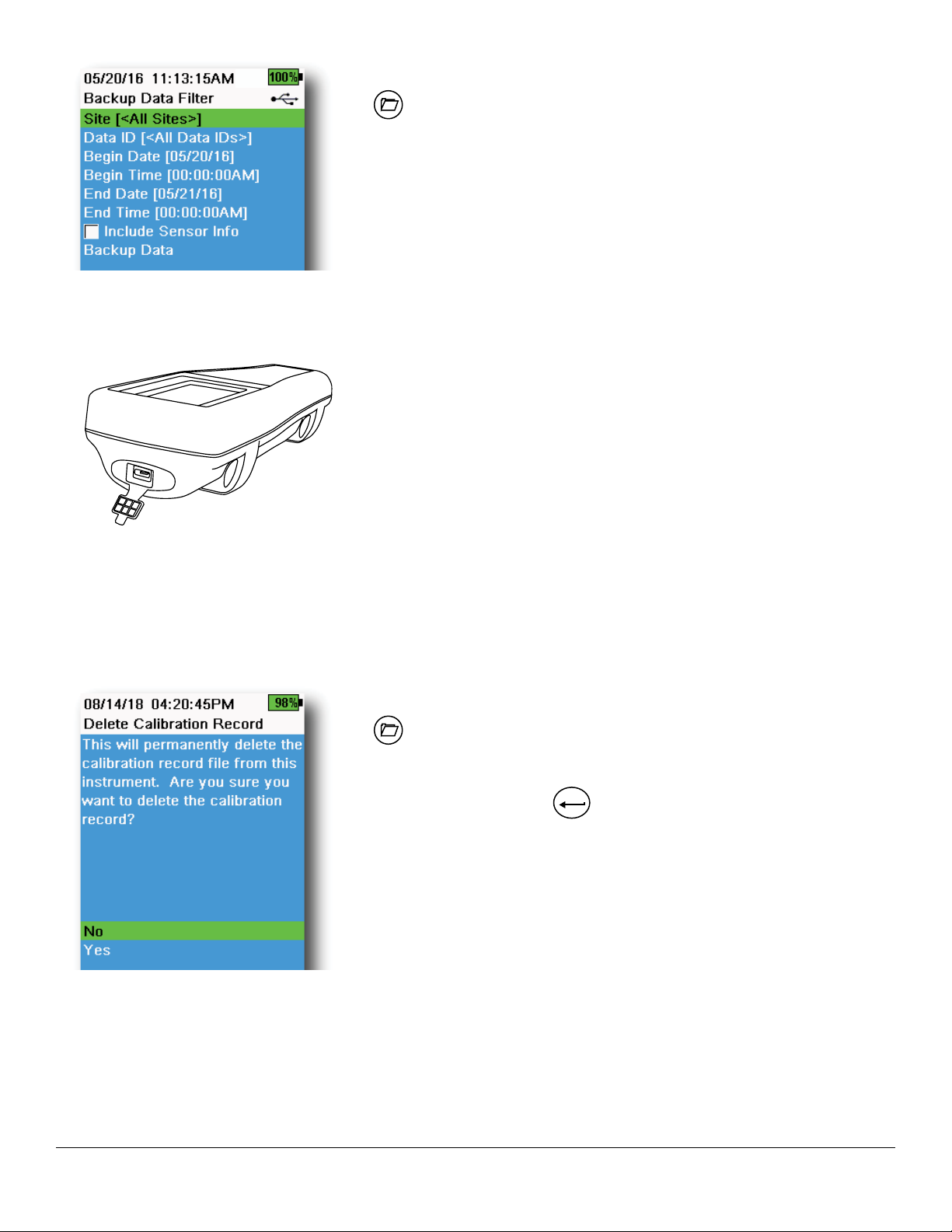
Backup Data
→ Backup Data
This function allows you to backup logged data to a flash drive based on
Site, Data ID, and log date (Figure 42). A USB female to micro USB male
adapter is included with new instruments for this data backup.
NOTE: The USB storage device must be formatted as FAT32, not
NTFS or exFAT. The handheld will only support FAT32.
Figure 42 Backup Data
Figure 43 Micro USB female
connector
If the box next to “Include Sensor Info” is checked, each data set will
be sent to a flash drive as a separate file with sensor serial number and
sensor software information included. If the box is not checked (default),
all data sets will be sent in a single backup file with no sensor serial
number or sensor software information.
NOTE: It is suggested to send data to the USB flash drive as
a single file (i.e. box is not checked) unless this sensor
information is needed. This makes importing the data much
faster and easier.
Once the filter settings are configured, select Backup Data to send the
data to a flash drive. The data is exported in a CSV file.
If the data backup is not successful, ensure the correct filter criteria are
selected and the USB connection indicator can be seen at the top of the
screen (Figure 9).
Delete Calibration Record
Figure 44 Delete Calibration Record
28
→ Delete Calibration Record
To permanently delete the Calibration Record file from the instrument,
select Yes , then push the
ENTER
key (Figure 44).
Operation
Page 29

2.9
For the highest accuracy, calibrate the sensor(s) before taking measurements.
1. Create Site and Data ID lists for logged data (if applicable).
2. Set the logging method (single or interval).
3. Set the Auto Stable parameters (if applicable).
4. Verify that the sensors and/or port plugs are correctly installed in all bulkhead ports.
5. Install the probe guard.
6. Insert the probe into the sample. Make sure the probe is fully submerged.
7. Move the probe in the sample to release any air bubbles and to provide a fresh sample to the sensors.
8. Wait for the sensor/s to stabilize in the sample.
9. On the main run screen, press
Taking Measurements
ENTER
to begin logging (single or interval) (See Logging).
NOTE: An option to change Site and/or Data ID (if enabled) appears once
ENTER
10. To stop continuous logging, simply press
key again.
ENTER
is pressed to begin logging.
Operation
29
Page 30

3. Calibration
ProDIGITAL sensors (except temperature) require periodic calibration. Calibration procedures follow the same basic
steps with variations for specific parameters. Before calibration, adjust Calibration Record settings under the System
menu if applicable to user requirements. Set up sensor options, settings, and coefficients as applicable.
3.1
Make sure the calibration cup, sensor guard, and all sensors are clean. YSI recommends installing the sensor guard
before placing the sensors into the calibration cup.
For highest data accuracy, thoroughly rinse the calibration cup and sensors with a small amount of the calibration
standard for the sensor to be calibrated. Discard the rinse standard, and proceed with a fresh standard.
Be careful to avoid cross-contamination with other standards between calibrations by thoroughly rinsing with DI water
and drying the calibration cup and sensors.
Ensure the calibration cup gasket is correctly seated. Loosely install the retaining nut on the cup. Slide the calibration
cup over the sensors and sensor guard and tighten the retaining nut (Figure 45).
Calibration Setup
Calibration Cup Installation for 4-Port Cable Assemblies
1 Fill line one (for all calibration
solutions except for conductivity)
4 5
3
2 Fill line two (for conductivity
calibration solution)
3 Gasket
2
1
Figure 45 Calibration cup standard volume (4-port cable)
30
4 Retaining nut
5 Calibration cup installed
It takes 170 mL of solution to fill the
calibration cup to line 1, while it takes
225 mL to fill to line 2.
Calibration
Page 31

Calibration Setup (continued)
Calibration Screen Layout
The calibration screen has the same basic layout for each parameter
(Figure 46).
Calibration value: This is the value the sensor will be calibrated to. The
Yellow Line on the graph corresponds to this value.
Accept Calibration: Select this to calibrate the sensor to the calibration
value.
Finish Calibration: This option is only available with multi-point
calibrations (i.e. pH, ISE, turbidity, PC, PE, and chlorophyll). Finishes the
calibration by applying previously accepted points.
Press ESC to Abort: Press the ESC key to leave the calibration. The sensor
will not be calibrated to any points. The last successful calibration will be
used.
Last Calibrated: View the date and time of the last successful sensor
calibration.
Figure 46 Layout of calibration screen
Actual Readings: This shows the current measurement value on the Run
screen. The White Line on the graph corresponds to this value. Observe
the White Line to ensure the measurement is stable before choosing
Accept Calibration.
Post Cal Value: This is the same as the calibration value. This will be the
measurement value in the current solution after the calibration is finished.
Calibration
31
Page 32

3.2
NOTE: This calibration option is available only if your bulkhead is equipped with a depth sensor.
Depth is calculated from the pressure exerted by the water column minus atmospheric pressure. Factors influencing
depth measurement include barometric pressure, water density, and temperature. Calibration in the atmosphere
“zeros” the sensor with respect to the local barometric pressure.
YSI recommends calibrating depth at the location of measurement. A change in barometric pressure will result in a
zero shift unless the transducer is recalibrated to the new pressure.
If applicable, enter the depth offset to set the depth measurement to something other than zero. Enter the altitude and
latitude of your sampling location to increase the accuracy of your depth measurement.
Depth
Depth Calibration
1. Make sure that the depth sensor is clean and dry in air, not im-
mersed in any solution. For best results, keep the bulkhead still
and in one position while calibrating.
Cal
2. Push the
to 0.000 and should not be changed for air calibrations, even if
using an offset.
3. Observe the actual measurement readings for stability (white line
on graph shows no significant change for 40 seconds), then select
Accept Calibration (Figure 47).
key, then select Depth. The Calibration Value is set
Figure 47 Calibrate Depth
If the depth offset is used, the depth measurement will be adjusted after
calibration.
32
Calibration
Page 33

3.3
The conductivity/temperature sensor can measure and calculate conductivity, specific conductance (temperature
compensated conductivity), salinity, non-linear function (nLF) conductivity, TDS, resistivity, and density. Calibration
is only available for specific conductance, conductivity, and salinity. Calibrating one of these options automatically
calibrates the other conductivity/temperature parameters listed above. For both ease of use and accuracy, YSI
recommends calibrating specific conductance.
Select the appropriate calibration standard for the conductivity of the sampling environment. Standards at least 1 mS/
cm (1000 μs/cm) are recommended for the greatest stability. For fresh water applications, calibrate to 1,000. For salt
water applications, calibrate to 50,000 μS.
Conductivity
Conductivity Calibration
1. Make sure the conductivity sensor is clean prior to calibration. If
necessary, clean the conductivity cell with the supplied soft brush.
2. Place the correct amount of conductivity standard into a clean and
dry or pre-rinsed calibration cup.
3. Carefully immerse the sensors into the solution. Make sure the
solution is above the vent holes on the side of the conductivity
sensor.
If using the ODO/CT assembly, ensure the vent holes at the top
of the sensor are completely immersed and the solution level is at
least 1 cm higher than the top vent holes (Figure 49). A graduated
cylinder is included with ODO/CT cable assemblies for the
purpose of calibrating conductivity.
For 4-port cable assemblies, fill the calibration cup to the second
line with fresh calibration standard. It takes 225 mL of solution to
fill to line 2.
4. Gently rotate and/or move the sensor up and down to remove any
bubbles from the conductivity cell. Allow at least 40 seconds for
Figure 48 Calibrate specific
conductance
Top Vent Holes
Side Vent
Holes
temperature equilibration before proceeding.
5. Push the
Conductance.
6. Select Calibration value then enter the calibration value of the
standard used. Note the measurement units the instrument is
reporting and calibrating and be sure to enter in the correct
calibration value for the units being used. For example, 10,000 μS
= 10 mS. Make sure that the units are correct and match the units
displayed on the handheld.
7. Observe the actual measurement readings for stability (white line
on graph shows no significant change for 40 seconds), then select
Accept Calibration (Figure 48). “Calibration successful!” will be
displayed in the message area.
Cal
key, select Conductivity, then select Specific
Figure 49 ODO/CT Cable Assembly
Calibration
(continued on next page)
33
Page 34

Conductivity Calibration (continued)
8. Rinse the sensor in clean water then dry.
NOTE: If the data is not stabilized after 40 seconds, gently rotate
the sensor or remove/reinstall the calibration cup to make
sure that no air bubbles are in the conductivity cell.
If you get calibration error messages, check for proper
sensor immersion, verify the calibration solutions is fresh,
the correct value has been entered into the handheld, and/
or try cleaning the sensor.
3.4
The barometer is factory calibrated and should rarely need to be recalibrated. The barometer is used for DO
calibration, %Local measurements, and for virtual vented depth measurements. Verify that the barometer is accurately
reading “true” barometric pressure and recalibrate as necessary.
Laboratory barometer readings are usually “true” (uncorrected) values of air pressure and can be used “as is” for
barometer calibration. Weather service readings are usually not “true”, i.e. they are corrected to sea level and cannot
be used until they are “uncorrected”. Use this approximate formula:
Barometer
True BP in mmHg=[Corrected BP in mmHg] - [2.5* (Local altitude in ft. above sea level/100)]
Example:
Corrected BP = 759 mmHg
Local altitude above sea level = 978 ft
True BP = 759 mmHg - [2.5*(978ft/100)] = 734.55 mmHg
Barometer Calibration
1. Push the
2. Select Calibration value then enter the correct “true” barometric
pressure.
Cal
key, then select Barometer.
Figure 50 Calibrate Barometer
34
NOTE: The measurement units during calibration are dictated by
what is enabled in the sensor setup menu. Be sure to enter
in the correct units.
• BP in mmHg=25.4 x BP inHg
• BP in mmHg=0.750062 x BP mb
• BP in mmHg=51.7149 x BP psi
• BP in mmHg=7.50062 x BP kPa
• BP in mmHg=760 x BP atm
3. Select Accept Calibration (Figure 50). “Calibration successful!” will
be displayed in the message area.
Calibration
Page 35

3.5
ODO calibration requires the current “true” barometric pressure. Make sure that the barometer is reading accurately
prior to ODO calibration.
Calibrating in DO% or DO% local automatically calibrates the mg/L and ppm measurement. There is no reason to calibrate both parameters. For both ease of use and accuracy, we recommend that you calibrate DO% or DO% Local and
not mg/L.
Dissolved Oxygen
ODO% and ODO% Local - Water
Saturated Air Calibration
1. Place a small amount of clean water (5 mL) in the calibration cup or
a wet sponge into the calibration sleeve (for ODO/T and ODO/CT
probes).
2. Make sure there are no water droplets on the ODO sensor cap or
temperature sensor.
3. Attach the probe guard and carefully slide into the calibration cup.
Make sure a seal is not created around the probe. Atmospheric
venting is required for accurate calibration.
4. Turn the instrument on and wait approximately 5 to 15 minutes for
the air in the storage container to be completely saturated with
water.
5. Push the
6. Observe the actual measurement readings for stability (white line
on graph shows no significant change for 40 seconds), then select
Accept Calibration (Figure 51). “Calibration successful!” will be
displayed in the message area.
Cal
key, then select ODO. Select DO%.
Figure 51 Calibrate ODO %
Calibration
NOTE: If you see a calibration error message, verify the barometer
reading and inspect the sensor cap. Clean and/or replace
the sensor cap as needed.
35
Page 36

Figure 52 Calibrate ODO mg/L
ODO mg/L Calibration
1. Place the ODO and conductivity/temperature sensor into a water
sample that has been titrated by the Winkler method to determine
the dissolved oxygen concentration in mg/L.
2. Push the
3. Select Calibration value.
4. Enter the dissolved oxygen concentration of the sample in mg/L.
5. Observe the actual measurement readings for stability (white line
on graph shows no significant change for 40 seconds), then select
Accept Calibration (Figure 52). “Calibration successful!” will be
displayed in the message area.
6. Rinse the bulkhead and sensors in clean water then dry.
Cal
key, then select ODO. Select DO mg/L.
Figure 53 Calibrate ODO zero point
ODO Zero Point Calibration
1. Place the ODO and Conductivity/Temperature sensors in a
solution of zero DO.
NOTE: A zero DO solution can be made by dissolving
approximately 8-10 grams of sodium sulfite into 500 mL
of tap water. Mix the solution thoroughly. It may take the
solution 60 minutes to be oxygen-free.
2. Push the
3. Observe the actual measurement readings for stability (white line
on graph shows no significant change for 40 seconds), then select
Accept Calibration (Figure 53). “Calibration successful!” will be
displayed in the message area.
4. Thoroughly rinse the bulkhead and sensors in clean water then
dry.
5. Perform a ODO % water-saturated air calibration after performing
a zero point calibration.
Cal
key, then select ODO. Select Zero.
36
Calibration
Page 37

3.6
Turbidity
Standards
For best results, YSI recommends the following standards for turbidity calibration:
Calibration Point Standard Value
1 0 FNU [SKU: 608000]
2 12.4 FNU [SKU: 607200] or 124 FNU [SKU: 607300]
3 1010 FNU [SKU: 607400]
Other standards may be acceptable as long as they have been prepared according to details in Standard Methods for
the Treatment of Water and Wastewater (Section 2130 B). These standards include:
• YSI Certified AMCO-AEPA polymer-based standards (see above)
• Hach StablCal™ standards in various NTU denominations
• Dilutions of 4000 NTU formazin concentrate purchased from Hach
• Other formazin standards prepared according to the Standard Methods
The use of standards other than those mentioned above will result in calibration errors and inaccurate field readings.
It is important to use the same type of standard for all calibration points; do not mix formazin and polymer-based
standards for different points in a multi-point calibration.
When using an alternative standard (non-YSI), calibration can be completed using the following limits:
Min Max Unit
1st Calibration Point 0.0 1.0 FNU or NTU
2nd Calibration Point 5.0 200 FNU or NTU
3rd Calibration Point 400 4000 FNU or NTU
Calibration
37
Page 38

Figure 54 Calibrate Turbidity
Turbidity Calibration 2-Point
Turbidity calibrations, more than most other paramters, are susceptible
to interference from contamination. It is critical for calibrations to be
performed with very clean sensors, guards, and cups.
NOTE: Calibration standards should not be re-used.
1. Fill the calibration cup to the appropriate level with 0 FNU
standard (deionized water may be used as a substitute). The
sensor guard must be installed to ensure an accurate calibration.
Make sure the guard is intalled and immerse the probe in the zero
standard.
Cal
2. Push the
3. Select Calibration Value and enter 0.00.
4. Make sure there are no air bubbles on the turbidity sensor lens.
If present, lightly tap the guard against the cup to dislodge any
bubbles. Observe the actual measurement readings for stability
(white line on graph shows no significant change for 40 seconds),
and then select Accept Calibration. “Ready for cal point 2” will be
displayed in the message area.
5. Discard the used standard, and rinse the probe, guard, and
calibration cup with a small amount of the next calibration point
standard. Discard the rinse standard.
6. Fill the calibration cup to the appropriate level with fresh standard
for the second calibration point. Immerse the probe in the
standard.
7. Select Calibration Value and enter the value of the second
calibration standard.
8. Make sure there are no air bubbles on the turbidity sensor lens.
Observe the actual measurement readings for stability, and then
select Accept Calibration (Figure 54). “Ready for cal point 3” will
be displayed in the message area.
9. Select Finish Calibration to complete a 2-point calibration or
continue for the 3-point calibration.
key, then select Turbidity.
38
Repeat steps 5 through 8 for a 3-point calibration. “Calibration
successful!” will be displayed in the message area. After calibration, rinse
with water and dry the probe.
Calibration
Page 39

3.7
Total Algae
TAL Sensors
YSI offers two Total Algae (TAL) sensor options. Both are dual-channel fluorescence sensors.
The channels on the TAL-PC sensor refer to two independent data sets: one results from a blue excitation beam
that excites the chlorophyll a (Chl) molecule and the second results from an orange excitation beam that excites the
phycocyanin (PC) accessory pigment. TAL-PC sensors are typically selected for monitoring freshwater cyanobacteria.
The TAL-PE sensor is similar in having a chlorophyll channel, but utilizes a slightly blueshifted beam that excites the
pigment phycoerythrin (PE). TAL-PE sensors are typically selected for monitoring marine cyanobacteria.
TAL Units
The TAL sensors report data in RFU and μg/L of pigment (Chl, PC or PE) units. YSI recommends reporting in Relative
Fluorescence Units (RFU).
RFU is used to set sensor output relative to a stable secondary standard, Rhodamine WT dye. This allows users to
calibrate sensors identically so that results from sensor to sensor can be compared. Calibration with Rhodamine
WT also enables users to monitor for sensor drift and external factors such as biofouling or declining sensor optical
performance over time as the LEDs age.
The excellent linearity of RFU, once the channels are calibrated with Rhodamine WT, translates to the best accuracy
of measurements. For example, a chlorophyll reading of 100 units will represent twice the pigment detected by
the sensor than with a chlorophyll reading of 50 units. This high linearity (R2>0.9999) doesn’t always hold for μg/L
of pigment since that unit was derived from laboratory monocultures, and an environmental algal population can
behave quite differently. This is also why the TAL sensors and in situ monitoring should not be regarded as a perfect
replacement for other methods such as pigment extractions and cell counting.
The μg/L output generates an estimate of pigment concentration that is based upon correlations built with sensor
outputs and extractions of pigments from laboratory-grown blue-green algae. Synonymous with parts per billion
(ppb), μg/L is still commonly used by regulatory agencies, but has the drawback that it is very dependent upon the
composition of the algal population, the time of day, the physiological health of the algae, and a number of other
environmental factors. Thus, users are advised to do their own check of our correlation with a population of algae
relevant to their own sites, as described below.
A 2-point RFU calibration is advised to be performed first. Next, with samples collected from the site of interest,
measure both RFU and μg/L with the sensor(s). Observing careful handling and preservation of the samples, as
soon as possible extract the pigments from the samples, using standardized methods to determine the μg/L in each
sample. The extraction data may be used to assess how RFU and μg/L delivered by the sensor compare with the μg/L
of pigment that would be predicted by RFU from the sensor. The user’s requirements can guide the decision as to
whether RFU or μg/L is the best unit to read from the sensor for any specific application.
TAL Raw values can only be seen under Sensor info in the System menu and are unaffected by user calibrations. These
values range from 0-100, representing the percent of full scale that the sensor detects in a sample, and are used for
diagnostic purposes.
Calibration
39
Page 40

Rhodamine WT Dye Solution Preparation
Rhodamine WT dye solution must be used when completing a 2-point calibration. Purchase Rhodamine WT as a 2.5%
solution to follow the procedure below. Kingscote Chemicals (Miamisburg, OH, 1-800-394-0678) has historically had a
2.5% solution (item #106023) that works well with this procedure. Note that there are many types of Rhodamine—make
sure Rhodamine WT is selected. If a 2.5% solution cannot be obtained commercially, prepare it from a solid or from
another concentration of a liquid solution to a 2.5% final concentration, or adjust the dilutions below accordingly. It
should be stored in the refrigerator when not in use.
For PC and chlorophyll channel calibrations, a 0.625 mg/L solution of Rhodamine WT should be prepared. For PE
channel calibration, a 0.025 mg/L solution of Rhodamine WT should be prepared. The steps below describe one
procedure to prepare these solutions.
1. For any TAL sensor calibration, prepare a 125 mg/L solution of Rhodamine WT. Transfer 5.0 mL of the 2.5%
Rhodamine WT solution into a 1000 mL volumetric flask. Fill the flask to the volumetric mark with deionized or
distilled water and mix well to produce a solution that is approximately 125 mg/L of Rhodamine WT. Transfer to
a storage bottle and retain it for future use.
*This solution can be stored in the refrigerator (4°C). Its degradation will depend upon light exposure
and repeated warming cycles, but solutions used 1-2 times a year can be stored for up to two years.
Users should implement their own procedures to safeguard against degradation.
2. For PC and chlorophyll channel calibrations, prepare a 0.625 mg/L solution of Rhodamine WT. Transfer 5.0 mL of
the 125 mg/L solution prepared in step one into a 1000 mL volumetric flask. Fill the flask to the volumetric mark
with deionized or distilled water. Mix well to obtain a solution that is 0.625 mg/L of Rhodamine WT. Use this
solution within 24 hours of preparation and discard it after use.
3. For PE channel calibration, prepare a 0.025 mg/L solution of Rhodamine WT. Transfer 0.2 mL of the 125
mg/L solution prepared in step one into a 1000 mL volumetric flask. Fill the flask to the volumetric mark with
deionized or distilled water. Mix well to obtain a solution that is 0.025 mg/L of Rhodamine WT. Use this solution
within 24 hours of preparation and discard it after use.
In addition to preparing the Rhodamine solution(s), it is also necessary to determine temperature-compensated
calibration values for solutions. In general, fluorescence is inversely related with temperature. Measure the temperature
of the Rhodamine solution(s) and use the temperature of the solution at the time of calibration to select the
compensated solution concentrations, in either RFU (recommended) or µg/L pigment equivalents, from the table
below.
As an example, assume that you will calibrate the chlorophyll channel in RFU, and that the temperature measured in
the 0.625 mg/L Rhodamine WT solution is 22°C. The first standard value entered will be 0, and the second standard
value will be 16.4 (see table on page 41). Likewise, if you intend to use the default µg/L unit when calibrating
chlorophyll, the second standard value would be 66 in this example. Using the same 0.625 mg/L Rhodamine WT
solution to calibrate the PC channel will yield a second standard value of 16.0 RFU or 16 µg/L. These values will be
entered when performing a 2-point calibration.
40
Calibration
Page 41

Rhodamine WT Dye Solution Preparation (continued)
Chlorophyll
Temp (°C)
30 14.0 56.5 11.4 11.4 37.3 104.0
28 14.6 58.7 13.1 13.1 39.1 109.0
26 15.2 61.3 14.1 14.1 41.0 115.0
24 15.8 63.5 15.0 15.0 43.0 120.0
22 16.4 66 16.0 16.0 45.0 126.0
20 17.0 68.4 17.1 17.1 47.0 132.0
18 17.6 70.8 17.5 17.5 49.2 138.0
16 18.3 73.5 19.1 19.1 51.4 144.0
14 18.9 76 20.1 20.1 53.6 150.0
12 19.5 78.6 21.2 21.2 55.9 157.0
10 20.2 81.2 22.2 22.2 58.2 163.0
8 20.8 83.8 22.6 22.6 60.6 170.0
RFU
μg/L
Phycocyanin
RFU
μg/L
Phycoerythrin
RFU
μg/L
TAL Calibration
A 1- or 2-point calibration can be completed for all channels on the TAL-PC and TAL-PE sensors.
A 1-point calibration, typically completed in clear deionized or distilled water, is simply a re-zeroing of the sensor.
This calibration does not reset the second point entered during the previous 2-point calibration. The consequence is
that error will be alleviated at and near zero, but more error can accumulate in the measurement the farther away from
zero the measured value is. The amount of error is dependent upon how much the second point drifts, which is not
always equivalent to how much the zero point drifts.
For many users, especially those with sites where pigment is rarely detected and values are at or near zero most of the
time, the far-from-zero accumulation of error is a non-issue. For others, it is best to perform a 2-point calibration using a
Rhodamine WT solution.
Calibration
41
Page 42

Figure 55 TAL-PC Calibration Options
Figure 56 TAL-PE Calibration Options
PE, PC and Chlorophyll Calibration 2-Point
Each channel of the sensor must be calibrated independently. Calibration
of the chlorophyll channel does not set the calibration for the PC channel
or the PE channel. In addition, calibrating in RFU for a channel does not
automatically calibrate the µg/L measurement for the same channel. The
following calibration procedure must be performed for each channel and
each unit the user would like to display.
1. Fill the calibration cup to the appropriate level with deionized
water (0 standard). Immerse the probe in the standard. Make sure
the sensor guard is installed.
Cal
2. Push the
on the sensor to be calibrated.
3. Select the channel and units to be calibrated. Options for the TAL-
PC sensor are shown in Figure 55, while options for the TAL-PE
sensor are shown in Figure 56.
4. Select Calibration Value and enter 0.00.
5. Make sure there are no air bubbles on the sensor lens. If present,
lightly tap the guard against the cup to dislodge any bubbles.
Observe the actual measurement readings for stability (white line
on graph shows no significant change for 40 seconds), and then
select Accept Calibration. “Ready for cal point 2” will be displayed
in the message area.
6. Discard the used water, and rinse the probe, guard, and calibration
cup with a small amount of the standard for calibration point #2.
Discard the rinse standard.
key, then select either TAL-PC or TAL-PE, depending
Figure 57 Calibrate PC RFU
NOTE: For standard #2, use the 0.625 mg/L Rhodamine WT
solution when calibrating chlorophyll (RFU or µg/L) on
either TAL sensor, or when completing a PC (RFU or µg/L)
calibration on a TAL-PC sensor. Use the 0.025 mg/L
Rhodamine WT solution when completing a PE (RFU or
µg/L) calibration on a TAL-PE sensor.
7. Fill the calibration cup to the appropriate level with fresh standard
#2. Immerse the sensors in the second calibration standard.
8. Observe the temperature reading on the calibration display
(Figure 57). Use the table in the Rhodamine WT dye solution
preparation section to identify the appropriate value for the
calibration standard.
9. Select Calibration Value and enter the value of the second
calibration standard.
10. Observe the actual measurement readings for stability (white line
on graph shows no significant change for 40 seconds), then select
Accept Calibration. The procedure will automatically finish after
calibrating using the second standard.
42
Calibration
Page 43

3.8
Observe the pH mV readings during calibration to understand the condition and response of the pH sensor. In buffer
7, pH mVs should be between -50 and +50. In pH4 buffer, the mV reading should be 165 to 185 mV higher than the
reading in pH 7 buffer. In pH 10 buffer, the mV reading should be 165 to 185 mV lower than the reading in pH 7 buffer.
The theoretically ideal slope is -59 mV/pH unit.
1-Point
While a 1-point pH calibration is possible, this calibration procedure adjusts only the pH offset and leaves the
previously determined slope unaltered. This should only be performed if you are adjusting a previous 2-point or
3-point calibration.
2-point
Perform a 2-point pH calibration if the pH of the media to be monitored is known to be either basic or acidic. In this
procedure, the pH sensor is calibrated with a pH 7 buffer and a pH 10 or pH 4 buffer depending upon the pH range
you anticipate for your water to be sampled.
3-point
Perform a 3-point pH calibration to assure maximum accuracy when the pH of the environmental water cannot be
anticipated or fluctuates above and below pH 7. In this procedure, the pH sensor is calibrated with pH 7, pH 10, and pH
4 buffer solutions.
pH/ORP
pH Calibration 3-Point
Figure 58 Calibrate pH 2- or 3-point
1. Always start the calibration with pH 7 buffer. Fill the calibration cup
to the appropriate level with pH 7 buffer solution.
2. With the probe guard installed, carefully immerse the probe into
the buffer solution. Make sure both the pH sensor and temperature
sensor are submerged.
3. Push the
4. The Calibration value will automatically be adjusted based on
the selected buffer and temperature. Alternatively, the Calibration
value can be manually entered..
5. Wait for the pH mV and temperature readings to stabilize; the
white line on the graph should be flat for about 40 seconds.
6. Select Accept Calibration and press the
point 2” will be displayed in the message area.
7. Rinse the probe and calibration cup. Fill to the appropriate level
with either pH 10 or pH 4 buffer solution; it doesn’t matter which
one comes next.
8. Immerse the probe into the buffer solution. The Calibration value
will automatically be adjusted based on the selected buffer and
temperature.
9. Wait for the pH mV and temperature readings to stabilize; the
white line on the graph should be flat for about 40 seconds.
10. Select Accept Calibration and press the
point 3” will be displayed in the message area.
Cal
key; then select pH or pH/ORP.
ENTER
key. “Ready for cal
ENTER
key. “Ready for cal
Calibration
43
Page 44

pH Calibration 3-Point (continued)
ORP Calibration
NOTE: For 2-Point calibrations, select Accept Calibration before
selecting Finish Calibration.
11. Rinse the probe and calibration cup. Fill to the appropriate level
with the final buffer solution.
12. Immerse the probe into the buffer solution. The Calibration value
will automatically be adjusted based on the selected buffer and
temperature.
13. Wait for the pH mV and temperature readings to stabilize; the
white line on the graph should be flat for about 40 seconds.
14. Select Accept Calibration and press the
ENTER
key. The procedure
will automatically finish after calibrating the third point.
1. Obtain a premixed standard solution that is approved for use
with Ag/AgCl ORP sensors or prepare a standard with a known
oxidation reduction potential (ORP) value. Zobell solution is
recommended.
2. With the probe guard installed, carefully immerse the probe
into the standard solution. Make sure both the ORP sensor and
temperature sensor are submerged.
3. Push the
Cal
key, then select pH/ORP, then ORP.
4. If using YSI Zobell solution, the Calibration value will
automatically be adjusted based on the temperature. Otherwise,
refer to the table included with the standard solution and enter the
mV value that corresponds to the temperature of the solution.
5. Wait for the ORP mV and temperature readings to stabilize; the
white line on the graph should be flat for about 40 seconds.
6. Select Accept Calibration and press the
ENTER
key. “Calibration
successful!” will be displayed in the message area.
44
Figure 59 Calibrate ORP
Calibration
Page 45

ISEs
3.9
Ammonium, Nitrate, & Chloride
YSI recommends a 2-point calibration for ISEs. For best results, use standards that differ by 2 orders of magnitude:
• 1 mg/L and 100 mg/L for Ammonium and Nitrate
• 10 mg/L and 1,000 mg/L for Chloride
ISE Calibration
1. Fill the calibration cup to the appropriate level standard for
calibration point #1. Immerse the probe in the standard.
Cal
key, then select the applicable ISE sensor.
Figure 60 Calibrate ISE
2. Push the
3. Select Calibration value and enter the value that corresponds to
the first calibration standard.
4. Observe the actual measurement readings for stability (white line
on graph shows no significant change for 40 seconds), then select
Accept Calibration. “Ready for cal point 2” will be displayed in the
message area.
5. Discard the used standard and rinse the probe and calibration cup
with a small amount of the next calibration point standard. Discard
the rinse standard.
6. Fill the calibration cup to the appropriate level with fresh standard
for the second calibration point. Immerse the probe in the
standard.
7. Select Calibration value and enter the value of the second
calibration standard.
8. Observe the actual measurement readings for stability, and then
select Accept Calibration (Figure 60). “Ready for cal point 3” will
be displayed in the message area.
9. Select Finish Calibration to complete a 2-point calibration.
Optimal mV for ISE calibration
Ammonium mV values
• NH4 1 mg/L = 0 mV +/- 20 mV (new sensor only)
• NH4 100 mg/L = 90 to 130 mV greater than the mV reading in the 1 mg/L standard
• The mV span between 1 mg/L and 100 mg/L values should be approximately 90 to 130 mV. The slope should be
45 to 65 mV per decade of ammonium concentration in mg/L
Nitrate mV values
• NO3 1 mg/L = 200 mV +/- 20 mV (new sensor only)
• NO3 100 mg/L = 90 to 130 mV less than the mV reading in the 1 mg/L mV standard
• The mV span between 1 mg/L and 100 mg/L values should be approximately 90 to 130 mV. The slope should be
-45 to -65 mV per decade of nitrate concentration in mg/L
Chloride mV values
• Cl 10 mg/L = 225 mV +/- 20 mV (new sensor only)
• Cl 1,000 mg/L = 80 to 130 mV < 10 mg/L mV value
• The mV span between 10 mg/L and 1000 mg/L values should be approximately 80 to 130 mV. The slope should be
-40 to -65 mV per decade of chloride concentration in mg/L
Calibration
45
Page 46

Chilled Third Calibration Point
The chilled 3-point calibration is recommended if there is a large temperature variation during sampling or when
the temperature of the media cannot be anticipated. The highest concentration solution and one of the lower
concentration solutions should be at ambient temperature. The other lower concentration solution should be chilled to
less than 10°C to prior calibration point.
1. Discard the used standard and rinse the probe and calibration cup with a small amount of the next calibration
point standard. Discard the rinse standard.
2. Fill the calibration cup to the appropriate level with fresh standard for the third calibration point. Immerse the
probe in the standard.
3. Select Calibration value and enter the value of the third calibration standard.
4. Observe the actual measurement readings for stability, and then select Accept Calibration. “Calibration
successful!” will be displayed in the message area.
Preparing Standards
We recommend using YSI calibration solutions whenever possible. However, qualified users can follow these recipes to
prepare their own standards.
CAUTION: Some of the chemicals required for these solutions could be hazardous under some conditions;
therefore, the standards should only be prepared by qualified chemists in laboratories where proper
safety precautions are possible. It is the responsibility of the user to obtain and study the MSDS for
each chemical and to follow the required instructions with regard to handling and disposal of these
chemicals.
Ammonium Standards
You will need:
• Solid ammonium chloride or a certified 100 mg/L NH
• Lithium acetate dihydrate
• Concentrated hydrochloric acid
• High purity water
• A good quality analytical balance
• A 1000 mL volumetric flask
• Accurate volumetric measuring devices for 100 mL and 10 mL of solution
• And a 1000 mL glass or plastic storage vessels
CAUTION: Hydrochloric acid is highly corrosive and toxic and should therefore be handled with extreme care in
a well-ventilated fume hood. The equivalent amount of a less-hazardous, more dilute sample of the
acid may be used if preferred.
100 mg/L Standard
1. Accurately weigh 0.3817 g of ammonium chloride and transfer quantitatively into a 1000 mL volumetric flask.
Add 2.6 g of lithium acetate dihydrate to the flask.
2. Add approximately 500 mL of distilled or deionized water to the flask. Swirl to dissolve all of the reagents and
then dilute to the volumetric mark with distilled or deionized water.
3. Mix well by repeated inversion and then transfer the 100 mg/L standard to a storage bottle.
4. Add 3 drops of concentrated hydrochloric acid to the bottle, then seal and agitate to assure homogeneity.
Alternatively, 100 mL of certified 100 mg/L NH
chloride.
+
-N from a supplier
4
+
-N standard can be used in place of the solid ammonium
4
46
Calibration
Page 47

Ammonium Standards (continued)
1 mg/L Standard
1. Accurately measure 10.0 mL of the above 100 mg/L standard solution into a 1000 mL volumetric flask. Add 2.6
g of lithium acetate dihydrate to the flask.
2. Add approximately 500 mL of distilled or deionized water. Swirl to dissolve the solid reagents and then dilute to
the volumetric mark with water.
3. Mix well by repeated inversion and then transfer the 1 mg/L standard to a storage bottle.
4. Add 3 drops of concentrated hydrochloric acid to the bottle, then seal and agitate to assure homogeneity.
Other concentrations can be made by altering the amount of ammonium chloride. All other ingredient concentrations
should remain unchanged.
Nitrate Standards
You will need:
• Solid potassium nitrate or a certified 1000 mg/l NO3-N from a supplier
• Magnesium sulfate, high purity water
• A good quality analytical balance
• 1000 mL volumetric flask
• Accurate volumetric measuring devices for 100 mL, 10 mL and 1 mL of solution
• And 1000 mL glass or plastic storage vessels
100 mg/L standard
1. Accurately weigh 0.7222 g of anhydrous potassium nitrate and transfer quantitatively into a 1000 mL volumetric
flask. Add 1.0 g of anhydrous magnesium sulfate to the flask.
2. Add approximately 500 mL of water to the flask. Swirl to dissolve all of the reagents, and then dilute to the
volumetric mark with distilled or deionized water.
3. Mix well by repeated inversion and then transfer the 100 mg/L standard to a storage bottle.
4. Rinse the flask extensively with water prior to its use in the preparation of the 1 mg/l standard. Alternatively, 100
mL of certified 1000 mg/L NO3-N standard can be used in place of the solid potassium nitrate.
1 mg/L standard
1. Accurately measure 10.0 mL of the above 100 mg/L standard solution into a 1000 mL volumetric flask. Add 1.0
g of anhydrous magnesium sulfate to the flask.
2. Add approximately 500 mL of distilled or deionized water. Swirl to dissolve the solid reagents, and then dilute
to the volumetric mark with water.
3. Mix well by repeated inversion and then transfer the 1 mg/L standard to a storage bottle.
Other concentrations can be made by altering the amount of potassium nitrate. All other ingredient concentrations
should remain unchanged.
Calibration
47
Page 48

Chloride Standards
You will need:
• Solid sodium chloride or a certified 1000 mg/L chloride solution from a supplier
• Magnesium sulfate
• High-purity water
• A good quality analytical balance
• 1000 mL volumetric flask
• An accurate 10 mL measuring devices
• And 1000 mL glass or plastic storage vessels
1000 mg/L Standard
1. Accurately weigh 1.655 grams of anhydrous sodium chloride and transfer into a 1000 mL volumetric flask.
2. Add 0.5 grams of anhydrous magnesium sulfate to the flask.
3. Add 500 mL of water to the flask, swirl to dissolve all of the reagents, then dilute to the volumetric mark with
water.
4. Mix well by repeated inversion, then transfer the 1000 mg/L standard to a storage bottle.
5. Rinse the flask extensively with water prior to its use in the preparation of the 10 mg/L standard. Alternatively,
simply add 0.5 grams of magnesium sulfate to a liter of a 1000 mg/L chloride standard from a certified supplier.
10 mg/L Standard
1. Accurately measure 10 mL of the above 1000 mg/L standard solution into a 1000 mL volumetric flask.
2. Add 0.5 grams of anhydrous magnesium sulfate to the flask.
3. Add 500 mL of water, swirl to dissolve the solid reagents, then dilute to the volumetric mark with water.
4. Mix well by repeated inversion, then transfer the 10 mg/L standard to a storage bottle.
48
Calibration
Page 49

4. Maintenance and Storage
Follow all maintenance and storage procedures in this section. Incorrect or unapproved maintenance and/or storage
can cause handheld, sensor or cable damage not covered by the warranty.
Storage terms are defined as follows:
Short-term Storage = Less than 4 weeks
Short-term storage is appropriate when the handheld, cables, and sensors will be used at regular intervals (daily,
weekly, etc.).
Long-term Storage = More than 4 weeks
During long periods of inactivity, such as the “off-season” for environmental monitoring, the instrument, sensors, and
cables should be placed in long-term storage.
YSI recommends cleaning and maintenance before long-term storage.
4.1
Figure 61 Handheld cleaning
ProDIGITAL Handheld
Wipe the keypad, screen, and case with a cloth dampened with a mild
solution of clean water and dish soap (Figure 61). Optimal storage
temperature of the handheld instrument is 0-45°C. The battery pack
permanently loses capacity at a faster rate when above 45°C.
Short-term Storage:
Assure that the handheld instrument is powered off, and store it in a
temperature-controlled, secure location. Ideally all ports should be covered
to prevent dust, water, or other contamination.
Long-term Storage:
In addition ot the short-term storage guidelines above, remove the battery
pack to prevent any damage from possible battery leaks. Reinstall the
battery cover. Store the battery pack in a dry place ideally around 25°C.
Maintenance and Storage
49
Page 50

4.2
Figure 62 Cable, bulkhead,
connector maintenance
4-Port Bulkhead
Wipe the cable and bulkhead with a cloth dampened with a mild solution
of clean water and dish soap. Make sure sensors or port plugs are
installed in ProDSS 4-port cable assemblies so the bulkhead ports do not
get wet when cleaning. Exposure to water can cause damage or corrosion
to the bulkhead connectors not covered by the warranty.
For short-term storage, YSI recommends leaving the sensors installed on
the bulkhead. The ODO, pH, and pH/ORP sensors must be kept in a moist
air environment; therefore, place a small amount of water (5-10 mL) in the
calibration cup and tighten the retaining nut to seal the storage chamber.
For long-term storage, YSI recommends uninstalling the sensors
from the bulkhead and following each sensor’s respective long-term
storage instructions. Inspect the bulkhead ports and cable connectors
for contamination. If dirty or wet, clean it with compressed air (Figure
62). Install the cap that protected the bulkhead during initial shipment.
Alternatively, install the bulkhead port plugs.
4.3
Figure 63 Sensor guard maintenance
Sensor Guard
Remove light bio-fouling with a cloth soaked in a mild solution of
clean water and dish soap. Soak in vinegar to remove hard growth and
deposits. Use a plastic scrub brush to remove any remaining bio-fouling.
Rinse the sensor guard with clean water (Figure 63).
NOTICE: Do not sand or polish the guard. Removal of the guard
coating can affect some sensor readings.
50
Maintenance and Storage
Page 51

4.4
Figure 64 Depth sensor flush
Depth Sensor
The depth sensor on 4-port ProDSS cables should be flushed after each
use. Fill the syringe (included with the maintenance kit) with clean water
and gently push water through the ports located on the bulkhead. Flush
until clean water flows from the opposite depth port (Figure 64).
The sensor can be stored wet or dry. For long-term storage, YSI
recommends storing the sensor dry.
NOTICE: Do not insert objects into the depth ports. Damage to
the depth transducer from incorrect cleaning is not
covered by the warranty.
4.5
To ensure optimal performance, it is important to keep the temperature sensor free of any deposits. Rinse the
thermistor after each use. If deposits have formed, use mild soapy water and a soft bristle cleaning brush. The sensor
can be stored wet or dry.
4.6
Temperature Sensor
Conductivity Sensor
The conductivity channels should be cleaned after each use. Dip the
sensor’s cleaning brush (included with the maintenance kit) in clean water,
insert the brush at the top of the channels, and sweep the channels 15 to
20 times (Figure 65).
If deposits have formed on the electrodes, use a mild solution of dish
soap and water to brush the channels. For heavy deposits, soak the
sensor in white vinegar, then scrub with the cleaning brush. Rinse the
channels with clean water following the sweepings or soak.
Figure 65 Channel brush
Maintenance and Storage
The sensor can be stored wet or dry. For long-term storage, YSI
recommends storing the sensor dry.
51
Page 52

4.7
Figure 66 ODO sensor window
Optical Dissolved Oxygen Sensor
The ODO sensor should be kept clean since some types of fouling may
consume oxygen which could affect the dissolved oxygen measurements.
To clean the sensor cap, gently wipe away any fouling with a lens cleaning
tissue that has been moistened with water to prevent scratches (Figure
66). Do not clean the ODO sensor with organic solvents as they may
damage the cap.
To minimize sensor drift, always store the ODO sensor in a wet or watersaturated air environment.
Short-term Storage:
Store the ODO sensor in a moist air environment. A storage sleeve with
a wet sponge or the calibration cup with a small amount of water is
recommended (Figure 67).
Figure 67 ODO short-term storage
Figure 68 ODO long-term storage
Long-term Storage:
• Method 1: Submerge the sensing end of the sensor in a container of
distilled or deionized water. Periodically check the level of the water to
make sure that it does not evaporate.
• Method 2: Wet the sponge located in the cap originally included
with the ODO sensor, then install on sensing end of the ODO sensor.
Replace the sponge if it becomes dirty.
For ProDSS ODO sensors, the sensor can be left on the 4-port bulkhead
or removed for long-term storage (Figure 68).
52
Maintenance and Storage
Page 53

ODO Sensor Rehydration
If the ODO sensor has accidentally been left dry for longer than 8
hours, it must be rehydrated. To rehydrate, soak the ODO sensor in
room temperature tap water for approximately 24 hours. After the soak,
calibrate the sensor (Figure 69).
Figure 69 ODO rehydration
ODO Sensor Cap
Optical DO sensor caps are warrantied for either 12 or 24 months depending on the model:
• ProDSS ODO Sensor Cap [SKU: 626890] = 12 months
• ODO Extended Warranty Sensor Cap [SKU: 627180] = 24 months
Depending on usage and storage practices, the cap may last longer than its warranty period.
As the ODO sensor caps ages, deterioration of the dye layer can reduce measurement stability and response time.
Periodically inspect the sensor cap for damage and large scratches in the dye layer. Replace the cap when readings
become unstable and cleaning the cap and DO recalibration do not remedy the symptoms.
Maintenance and Storage
53
Page 54

Figure 70 ODO cap replacement
ODO Sensor Cap Replacement
The instruction sheet shipped with the replacement ODO sensor cap
includes the calibration coefficients specific to that sensor cap. Make sure
to save the ODO sensor cap instruction sheet in case you need to reload
the calibration coefficients.
1. Remove the old sensor cap assembly from the probe by grasping
the probe body with one hand and rotating the sensor cap
counterclockwise until it is completely free. Do not use any tools
for this procedure.
2. Carefully remove the o-ring by pinching it with your fingers and
rolling it up. Do not use any tools to remove the o-ring. Clean the
area of any debris with a lens cleaning tissue.
3. Install the new o-ring that is included with the replacement sensor
cap.
4. Apply a thin coat of o-ring lubricant (included with the new cap) to
the installed o-ring. Remove any excess o-ring lubricant with a lens
cleaning tissue. Be careful to avoid contact with the sensor lens.
5. Inspect the sensor lens for any moisture or debris. If necessary,
wipe the lens carefully with a non-abrasive, lint-free cloth to
prevent scratches. Do not use organic solvents to clean the ODO
sensor lens.
6. Remove the new sensor cap from its hydrated container and dry
the inside cavity of the sensor cap with lens cleaning tissue. Make
sure the cavity is completely dry before proceeding with the
installation.
7. Using clockwise motion, thread the new sensor cap onto the probe
assembly until it is finger-tight. The o-ring should be compressed
between the sensor cap and probe. Do not over-tighten the sensor
cap and do not use any tools for the installation process.
8. After installing the new sensor cap, store the sensor in either water
or in the water-saturated air storage chamber.
54
NOTE: Be sure to update the ODO Sensor Cap Coefficients after
replacement.
Maintenance and Storage
Page 55

Updating the ODO Sensor Cap Coefficients
After installing a new sensor cap, connect the probe to the handheld and turn the instrument on. Locate the Calibration
Code Label on the ODO Sensor Cap Instruction Sheet. This contains the calibration codes for this particular sensor
cap. Follow the procedures below to enter the new calibration coefficients into the instrument.
1. Push the
2. Select Sensor Cap Coefficients.
3. Highlight each coefficient in turn (K1 through KC) and use the numeric entry screen to enter the corresponding
new coefficient from the Calibration Code Label. Push the
next K selection.
4. After all the new coefficients have been entered, select Update Sensor Cap Coefficients.
5. A message will appear warning that you will be overwriting the current sensor cap coefficients and you should
confirm that you wish to carry out this action. Select Yes to confirm the new coefficients.
After updating the Coefficients, the Serial # in the Sensor Cap menu will be updated automatically based on your
entries.
If errors are made in entering the Sensor Cap Coefficients, the instrument will block the update and an error message
will appear on the display. If you see this error message, re-enter the coefficients and check them carefully.
NOTE: After entering the sensor cap coefficients, the ODO sensor must be calibrated.
key to access the Sensor menu, then select Setup, then ODO.
ENTER
key after each entry and then proceed to the
Maintenance and Storage
55
Page 56

4.8
Figure 71 Sensor window
Turbidity & Total Algae Sensors
Clean the sensing window with a non-abrasive, lint-free cloth (Figure 71).
If necessary, use mild soapy water.
The sensor can be stored wet or dry. For long-term storage, YSI
recommends storing the sensor dry. Install the shipping cap or sensor
guard to prevent scratches or damage to the optical sensing window.
4.9
The pH and pH/ORP sensors are shipped with their tips in a storage bottle containing potassium chloride (KCl)
solution. Keep this bottle for long-term storage.
Periodic maintenance is necessary to clear contamination from the sensing elements. Contaminants on the bulb and/or
junction can slow sensor response time. Clean the sensors when deposits, bio-fouling or other contamination appears
on the glass or when the sensor response time is noticeably slow. There are several methods to clean and restore the
sensor depending on the severity of fouling or contamination.
pH/ORP Sensor
Cleaning Methods
Standard Rinse
Rinse the sensor with tap water each time it is brought in from the field. This is generally recommended for most
sensors and use cases to clear mild contamination.
If contaminants remain or the sensor exhibits a slow response time, continue with advanced cleaning.
Advanced Cleaning
For moderate contamination or slow response after advanced rinsing,
remove the sensor from the bulkhead and perform the following steps:
1. Remove any foreign matter from the sensor tip. If necessary, use a
moistened cotton swab to carefully remove foreign material from
the glass bulb and junction. Be careful to avoid direct contact with
the glass bulb. The bulbs are fragile and will break if pressed with
sufficient force.
Figure 72 Cleaning the pH and
pH/ORP sensor with dish soap
2. Soak for 10 minutes in a mild solution of clean water and dish soap
(Figure 72). Rinse the sensor with tap water and inspect.
56
If contaminants are removed, attach the sensor to the bulkhead and test
the response time.
If contaminants remain or response time does not improve, continue to
the hydrochloric acid (HCl) soak.
Maintenance and Storage
Page 57

pH/ORP Sensor Maintenance and Storage (continued)
1 M HCl
Chlorine
Acid Soak
For heavy contamination or slow response after advanced cleaning,
remove the sensor from the bulkhead and perform the following steps:
1. Soak the sensor for 30 to 60 minutes in one molar (1 M) HCl
(Figure 73). HCl reagent can be purchased from most chemical or
laboratory distributors. To prevent injury, carefully follow the HCl
1 M HCl
Figure 73 Cleaning the pH and
pH/ORP sensor with hydrochloric acid
Attach the sensor to the bulkhead and test the response time. If response
time does not improve or biological contamination of the reference
junction is suspected, continue to the chlorine bleach soak.
Bleach Cleanse
If biological contamination of the reference junction is suspected or if
good response is not restored by the previous methods, remove the
sensor from the bulkhead and perform the following steps:
manufacturer’s instructions. If HCl is not available, soak in white
vinegar.
2. After soaking, thoroughly rinse the sensor with tap water. Then
soak the sensor in clean tap water for 60 minutes, stirring
occasionally. Finally, rinse the sensor once again with tap water.
bleach
Figure 74 Cleaning the pH and
pH/ORP sensor with chlorine bleach
1. Soak the sensor for 60 minutes in a 1:1 dilution of chlorine bleach
and tap water.
2. After soaking, thoroughly rinse the sensor with tap water. Then
soak the sensor in clean tap water for 60 minutes. Finally, rinse the
sensor once again with tap water.
Attach the sensor to the bulkhead and test the response time. If response
time does not improve the sensor may be nearing the end of its useful
life.
Short-term Storage:
When in regular field use, the pH-pH/ORP sensors should remain on the
bulkhead with the calibration/storage cup installed. Place a small amount
of tap or surface water in the cup prior to storage or transport. The
probes should be kept in this water-saturated air chamber between uses;
not submerged (Figure 75). Make sure the storage cup makes a tight
connection to prevent evaporation.
Figure 75 pH and pH/ORP
short-term storage
Maintenance and Storage
57
Page 58

pH/ORP Sensor Maintenance and Storage (continued)
Long-term Storage:
Remove the sensor from the bulkhead and plug the bulkhead port. Insert
the sensor tip into the storage bottle and solution that were originally
supplied with the sensor (Figure 76). The storage bottle features an open
cap and o-ring to form a tight seal around the sensor tip; the solution
contains KCl with potassium phthalate and a preservative. If this original
solution is not available, one can prepare a 2 M KCl solution or use pH
4 buffer as an alternative, though these solutions should be monitored
for microbial growth and replaced if growth is apparent. Other sensors
and system components should not be stored in or exposed to these pH
buffers for long periods of time.
Figure 76 pH and pH/ORP
long-term storage
NOTICE: Do NOT let the sensor dry out. Do NOT store the sensor
in distilled or deionized water. Either of these will
radically shorten the lifespan of the sensor module and
void its warranty.
Sensor Module
The pH and pH/ORP sensors feature user-replaceable sensor modules. These modules contain a reference solution
that depletes over time. The warranty period for both of these modules is 12 months:
• Replacement pH Module [SKU: 626963] = 12 months
• Replacement pH/ORP Module [SKU: 626964] = 12 months
Depending on usage and storage practices, the module may last longer than its warranty period. Replace the module
if the sensor exhibits a slow response time after trying all the cleaning methods listed above.
58
Maintenance and Storage
Page 59

4.10
ISE sensors are shipped with their tips in a storage bottle. Keep this bottle for long-term storage.
Do not let the ISE sensor reference electrode junctions dry out. Clean the sensors when deposits, bio-fouling or other
contamination appears on the membrane.
ISE Sensor
Ammonium and Nitrate Sensor Maintenance
1. Carefully clean the ammonium or nitrate sensor by rinsing with DI
water followed by soaking in the high standard calibration solution.
2. Carefully dab the sensor dry with a clean, lint-free cloth.
NOTICE: The ion-selective membranes are very fragile. Do not
use coarse material (e.g. paper towels) to clean the
membranes or permanent damage to the sensor can
occur. The only exception is fine emery cloth on the
chloride sensor.
Figure 77 Ammonium and nitrate
maintenance
Figure 78 Chloride maintenance
Chloride Sensor Maintenance
1. Carefully clean the chloride sensor by carefully polishing with
fine emery paper in a circular motion to remove deposits or
discoloration.
2. Carefully rinse with DI water to remove any debris.
Short-term Storage:
When in regular field use, ISEs should remain on the bulkhead with the
calibration/storage cup installed. Place a small amount of tap or surface
water in the cup prior to storage or transport. The probes should be kept
in this water-saturated air chamber between uses; not submerged. Make
sure the storage cup makes a tight connection to prevent evaporation
(Figure 79).
Figure 79 ISE short-term storage
Maintenance and Storage
59
Page 60

ISE Sensor Maintenance and Storage (continued)
Long-term Storage:
Remove the sensor from the bulkhead and plug the bulkhead port.
Insert the sensor tip into the storage bottle with a small amount of
high-calibration solution or tap water. The sensor tip should not be
submerged. The storage bottle features an open cap and o-ring to form a
tight seal around the sensor tip (Figure 80).
NOTICE: Do NOT let the sensor dry out. Do NOT store the ISE
sensor in conductivity standard, pH buffer, or salt water.
Either of these will radically shorten the lifespan or kill
the sensor module and void its warranty.
Figure 80 ISE long-term storage
Rehydrating the Reference Junction
If an ISE module has been allowed to dry, soak the sensor for several
hours (preferably overnight) in the sensor’s high-calibration solution. If the
sensor is irreparably damaged, the sensor module must be replaced.
Sensor Module
Ammonium, chloride and nitrate sensors feature user-replaceable sensor modules. These modules contain a reference
solution that depletes over time. The warranty period for ISE modules is 6 months:
• Replacement Nitrate Module [SKU: 626965] = 6 months
• Replacement Ammonium Module [SKU: 626966] = 6 months
• Replacement Chloride Module [SKU: 626967] = 6 months
Depending on usage and storage practices, the module may last longer than its warranty period. When it is time,
perform a sensor module replacement in a clean, dry laboratory environment.
60
Maintenance and Storage
Page 61

4.11
Sensor modules for pH, pH/ORP, nitrate, ammonium, and chloride all require periodic replacement. Perform a sensor
module replacement in a clean, dry laboratory environment. Remove the sensor from the bulkhead and perform the
following steps:
ProDSS Sensor Module Replacement
Module Replacement
1. Peel off and discard the sticker that covers the junction of the
sensor body and the module (Figure 81).
2. With a small, flat-blade screwdriver, carefully remove the square
rubber plug from the gap in the hard plastic ring at the base of the
sensor module.
3. Using two fingers, squeeze the sensor module’s hard plastic ring
so that it compresses the gap left by the rubber plug.
4. While squeezing, steadily pull the sensor module straight from the
sensor body, rocking slightly if necessary. Do not keep the used
o-rings as they are unusable after removal from the sensor body.
Discard the old sensor module.
5. Inspect the sensor connector port for debris or moisture.
If detected, remove it with lint-free cloth or a light blast of
compressed air.
6. The new sensor module comes with two o-rings installed and
pre-lubricated. Visually inspect the o-rings for nicks, tears,
contaminants or particles. Replace any damaged o-rings.
Figure 81 Sensor module
replacement
NOTICE: If a sensor module is removed for any reason, the o-rings
must be replaced.
7. Align the prongs on the base of the sensor module with the slots
in the sensor body. The sensor module is keyed to insert in only
one orientation. Push the sensor module firmly into position until
it clicks. Wipe any excess o-ring lubricant from the assembled
components.
8. Wrap the junction of the sensor module and sensor body with the
new sticker included in the sensor module kit. The sticker helps
keep the sensor module junction clean and retain the rubber plug
throughout deployment.
9. Write the replacement date on the sticker.
NOTE: Be sure to calibrate the sensor after module replacement.
Maintenance and Storage
61
Page 62

5. KorDSS Software
5.1
KorDSS Software and drivers require permissions for successful installation. Administrative privileges may be necessary
for a business or networked PC. Contact your organization’s IT department for admin privileges.
Introduction
System Requirements
Supported 32 bit (x86) and 64 bit (x64) Microsoft Operating Systems:
• Microsoft Windows 7 Home Basic SP1
• Microsoft Windows 7 Home Premium SP1
• Microsoft Windows 7 Professional SP1
• Microsoft Windows 7 Enterprise SP1
• Microsoft Windows 7 Ultimate SP1
• Microsoft Windows 8 Home Basic
• Microsoft Windows 8 Home Premium
• Microsoft Windows 8 Professional
• Microsoft Windows 8 Enterprise
• Microsoft Windows 8.1 Basic
• Microsoft Windows 8.1 Professional
• Microsoft Windows 8.1 Enterprise
• Microsoft Windows 10 Home
• Microsoft Windows 10 Professional
• Microsoft Windows 10 Enterprise
• Microsoft Windows 10 Education
Ram Memory Requirement:
• Minimum of 2 GB of RAM installed
Hard Disk Free Space:
• Minimum of 500 MB of free hard drive space
Internet Access Required to Support:
• Software and device updates, software licensing
62
KorDSS Software Installation
Page 63

5.2
Figure 82 KorDSS Installer
Figure 83 ProDSS Driver Installer
Figure 84 Back button
Installing the Driver and Software
Follow these steps to complete the installation process and establish
connection to the handheld:
NOTE: Be sure to install the driver before connecting the handheld
to your PC for the first time.
1. Insert the supplied USB flash drive into a USB port on your
computer.
2. Depending on the PC operating system and system settings, the
KorDSS Installer may appear. If it does not appear, open the flash
drive in Windows Explorer and double-click Start.exe to start
the installer. Figure 82 shows how the installer will appear once it
starts.
3. On the KorDSS Installer, click Install Driver. Then choose to Install
the driver on the screens that follow (Figure 83).
4. After the driver has installed, choose to go Back to the KorDSS
Installer (Figure 84) .
5. On the KorDSS Installer, click Install KorDSS Application. A
license agreement will appear (Figure 85).
6. You may be asked if you want to allow a program from an
unknown publisher to make changes on the computer. If so, select
Yes .
7. After successful installation of KorDSS, click Launch to start the
program (Figure 86).
8. Connect the handheld meter to the PC with the supplied USB
cable.
9. Power on the handheld and click Connect when it appears under
the Instrument Connection Panel; there may be a short delay
before it appears in the software.
Figure 85 KorDSS license agreement
Figure 86 Launch KorDSS
KorDSS Software Installation
63
Page 64

6. Accessories
6.1
Telephone: 800 897 4151 (USA)
+1 937 767 7241 (Globally) Monday through Friday
8:00 AM to 5:00 ET
Fax: +1 937 767 9353 (orders)
Email: info@ysi.com
Mail: YSI Incorporated 1725 Brannum Lane
Yellow Springs, OH 45387 USA
Web: Visit YSI.com to order replacement parts, accessories, and calibration stolutions.
When placing an order please have the following available:
1. YSI account number (if available)
2. Name and phone number
3. Purchase Order or Credit Card number
4. Model Number or brief description
5. Billing and shipping addresses
6. Quantity
Ordering
64
Accessories
Page 65

ProDIGITAL Handhelds
YSI Item # Description
626650 ProSolo handheld, no GPS, not compatible with ProDSS 4-port cable assemblies
626870-1 ProDSS handheld, no GPS
626870-2 ProDSS handheld with GPS
ProDIGITAL Probe Assemblies
NOTE: The ODO and OBOD sensor caps come pre-installed on the following probe assemblies, with calibration
coefficients of the sensor cap pre-loaded into the probe at the factory.
YSI Item # Description
Optical Dissolved Oxygen and Temperature Probes
627200-1 ODO/T Probe Assembly, 1m
627200-4 ODO/T Probe Assembly, 4m
627200-10 ODO/T Probe Assembly, 10m
627200-20 ODO/T Probe Assembly, 20m
627200-30 ODO/T Probe Assembly, 30m
627200-50 ODO/T Probe Assembly, 50m
627200-100 ODO/T Probe Assembly, 100m
Optical Dissolved Oxygen, Conductivity, and Temperature Probes
627150-1 ODO/CT Probe Assembly, 1m
627150-4 ODO/CT Probe Assembly, 4m
627150-10 ODO/CT Probe Assembly, 10m
627150-20 ODO/CT Probe Assembly, 20m
627150-30 ODO/CT Probe Assembly, 30m
627150-50 ODO/CT Probe Assembly, 50m
627150-100 ODO/CT Probe Assembly, 100m
Self-Stirring Optical Biochemical Oxygen Demand Probes
626400 ProOBOD probe assembly (lab BOD probe); U.S./Japanese version with power supply
626401 ProOBOD probe assembly (lab BOD probe); International version with power supply
Accessories
65
Page 66

ProDSS 4-Port Cable Assemblies (No Sensors Included)
YSI Item # Description
626909-1 ProDSS-1 meter 4-port cable assembly, no depth
626909-4 ProDSS-4 meter 4-port cable assembly, no depth
626909-10 ProDSS-10 meter 4-port cable assembly, no depth
626909-20 ProDSS-20 meter 4-port cable assembly, no depth
626909-30 ProDSS-30 meter 4-port cable assembly, no depth
626909-40 ProDSS-40 meter 4-port cable assembly, no depth
626909-50 ProDSS-50 meter 4-port cable assembly, no depth
626909-60 ProDSS-60 meter 4-port cable assembly, no depth
626909-70 ProDSS-70 meter 4-port cable assembly, no depth
626909-80 ProDSS-80 meter 4-port cable assembly, no depth
626909-90 ProDSS-90 meter 4-port cable assembly, no depth
626909-100 ProDSS-100 meter 4-port cable assembly, no depth
626910-1 ProDSS-1 meter 4-port cable assembly, with depth
626910-4 ProDSS-4 meter 4-port cable assembly, with depth
626910-10 ProDSS-10 meter 4-port cable assembly, with depth
626911-20 ProDSS-20 meter 4-port cable assembly, with depth
626911-30 ProDSS-30 meter 4-port cable assembly, with depth
626911-40 ProDSS-40 meter 4-port cable assembly, with depth
626911-50 ProDSS-50 meter 4-port cable assembly, with depth
626911-60 ProDSS-60 meter 4-port cable assembly, with depth
626911-70 ProDSS-70 meter 4-port cable assembly, with depth
626911-80 ProDSS-80 meter 4-port cable assembly, with depth
626911-90 ProDSS-90 meter 4-port cable assembly, with depth
626911-100 ProDSS-100 meter 4-port cable assembly, with depth
ProDSS Sensors (for 4-Port Cable Assemblies)
YSI Item # Description
626900 Optical dissolved oxygen sensor
626902 Conductivity and temperature sensor
626901 Turbidity sensor
626903 pH sensor with module
626904 pH/ORP sensor with module
626906 Ammonium sensor with module
626905 Nitrate sensor with module
626907 Chloride sensor with module
626210 Total algae sensor, PC
626211 Total algae sensor, PE
66
Accessories
Page 67

Replacement Sensor Modules and ODO Sensor Caps
YSI Item # Description
626890 Replacement ProDSS Optical Dissolved Oxygen sensor cap (for 626900 smart sensor)
626482 Replacement ProOBOD Optical Dissolved Oxygen sensor cap (for 626400 or 626401 lab probes)
627180 Replacement ODO Extended Warranty Sensor Cap (only compatible with ODO/T and
ODO/CT probe assemblies)
626963 Replacement ProDSS pH sensor module
626964 Replacement ProDSS pH/ORP sensor module
626966 Replacement ProDSS Ammonium sensor module
626965 Replacement ProDSS Nitrate sensor module
626967 Replacement ProDSS Chloride sensor module
Calibration Standards
YSI Item # Description
065270 Conductivity standard, 1000 μmhos/cm (quart, glass); ideal for fresh water
065272 Conductivity standard, 10000 μmhos/cm (quart, glass); ideal for brackish water
065274 Conductivity standard, 100000 μmhos/cm (quart, glass); ideal for supersaturated sea water
060907 Conductivity standard, 1000 μmhos/cm (box of 8 individual pints, plastic); ideal for fresh water
060906 Conductivity standard, 1413 μmhos/cm, ±1%, 0.01 M KCl (box of 8 individual pints, plastic)
060911 Conductivity standard, 10000 μmhos/cm (box of 8 individual pints, plastic); ideal for brackish water
060660 Conductivity standard, 50000 μmhos/cm (box of 8 individual pints, plastic); ideal for sea water
061320 ORP (mV) standard, Zobell solution, powder - needs hydrated (125 mL bottle, plastic)
061321 ORP (mV) standard, Zobell solution, powder - needs hydrated (250 mL bottle, plastic)
061322 ORP (mV) standard, Zobell solution, powder - needs hydrated (500 mL bottle, plastic)
003821 pH 4 buffer (box of 6 individual pints, plastic); ideal for storage solution for pH sensor
003822 pH 7 buffer (box of 6 individual pints, plastic)
003823 pH 10 buffer (box of 6 individual pints, plastic)
603824 Assorted case of pH 4, 7, and 10 buffers (2 individual pints of each buffer, plastic)
005580 Confidence solution to verify conductivity, pH and ORP system (box of 6 individual 475 mL bottles,
plastic). Note: Not for calibration
003841 Ammonium standard, 1 mg/L (500 mL, plastic)
003842 Ammonium standard, 10 mg/L (500 mL, plastic)
003843 Ammonium standard, 100 mg/L (500 mL, plastic)
003885 Nitrate standard, 1 mg/L (500 mL, plastic)
003886 Nitrate standard, 10 mg/L (500 mL, plastic)
003887 Nitrate standard, 100 mg/L (500 mL, plastic)
608000 Turbidity standard, 0 FNU (1 gallon, plastic)
607200 Turbidity standard, 12.4 FNU (1 gallon, plastic)
607300 Turbidity standard, 124 FNU (1 gallon, plastic)
607400 Turbidity standard, 1010 FNU (1 gallon, plastic)
Accessories
67
Page 68

ProDIGITAL Accessories
YSI Item # Description
626946 Large, hard-sided carrying case (Fits ProDSS 4-port cables 10, 20, and 30 meters in length, cable
management kit, handheld, and accessories)
603075 Large, soft-sided carrying case
626945 Small, hard-sided carrying case (Fits ProDSS 4-port cables 1 and 4 meters in length, handheld, flow
cell, and accessories)
599080 Flow cell for ProDSS 4-port cables
603076 Flow cell for ODO/CT cables (requires single port adapter; 603078)
603078 Adapter required for ODO/CT flow cell (603076)
603056 Flow cell mounting spike
063507 Tripod (screws into back of meter)
063517 Ultra clamp (screws into back of meter)
603070 Shoulder strap
603069 Belt clip (screws into back of meter)
626942 USB car charger
626943 Small external Li-Ion rechargeable battery pack (Typical performance: will charge a completely
discharged handheld battery to about 50%)
626944 Large external Li-Ion rechargeable battery pack (Typical performance: will charge a completely
discharged battery to full charge, plus have power to charge a second battery to 20%)
626940 AC charger (USA). Includes power supply and USB cable (included with handheld)
626941 AC charger (international). Includes power supply, USB cable and outlet adapters (included with
handheld)
626846 Replacement Lithium-ion battery pack
626969 USB flash drive (included with handheld)
626991 Cable for charging and PC connection (included as part of 626940 and 626941)
626992 Cable for connection to USB drive (included with handheld)
626990 ProDSS maintenance kit (included with all ProDSS 4-port cables):
• 3 port plugs
• 1 tube of o-ring lubricant
• 1 brush
• 1 syringe
• 1 sensor installation/removal tool
• O-rings (6)
626919 Sensor guard for 4-port ProDSS cable assembly (included with all 4-port cables)
599786 Calibration/storage cup for 4-port ProDSS cable assembly (included with all 4-port ProDSS cables)
627195 Calibration cup for ODO/CT cable assembly (included with all ODO/CT cables)
603062 Cable management kit (included with ProDSS 4-port cables 10, 20, and 30-meters long; ODO/CT
cables 4, 10, 20, and 30-meters long; and ODO/T cables 4, 10, 20, and 30-meters long)
626918 1 lb weight (included with ProDSS 4-port cables 10-meters and longer)
605978 4.9 oz weight
68
Accessories
Page 69

7. Safety and Support
Rechargeable Lithium-Ion Battery Pack
7.1
Safety Warnings and Precautions
CAUTION: Failure to follow the safety warnings and precautions can result in fire, personal injury and/or
equipment damage not covered under warranty.
CAUTION: If the internal battery fluid comes into contact with skin, wash the affected area(s) with soap and
water immediately. If it comes into contact with your eye(s), flush them with generous amounts of
water for 15 minutes and seek immediate medical attention.
CAUTION: Always keep batteries away from children.
WARNING: In the unlikely event a lithium-ion battery catches fire, DO NOT attempt to put the fire out with
water, use a Class A, B or C fire extinguisher.
Do:
• Store the battery pack in a cool, dry, ventilated area.
• Store the battery pack in a non-conductive and fireproof container.
• Store the battery pack at approximately 50% of the capacity.
• Disconnect the battery pack when not in use and for long-term storage.
• Follow applicable laws and regulations for transporting and shipping of batteries.
• Immediately discontinue use of the battery pack if, while using, charging or storing the battery pack:
• Emits an unusual smell
• Feel hot
• Changes color
• Changes shape
• Appears abnormal in any other way.
Battery Pack General Precautions:
• DO NOT put the battery in fire or heat the battery.
• DO NOT connect the positive and the negative terminal of the battery to each other with any metal object
(e.g. wire).
• DO NOT carry or store the battery pack with neckaces, hairpins or other metal objects.
• DO NOT carry or store the battery pack with hazardous or combustible materials.
• DO NOT pierce the battery pack with nails, strike with a hammer, step on or otherwise subject the battery pack to
strong impacts or shocks.
• DO NOT solder directly onto the battery pack.
• DO NOT expose the battery pack to water or salt water or allow it to get wet.
• DO NOT disassemble or modify the battery pack. The battery contains safety and protection devices that, if
damaged, can cause the battery to generate heat, rupture or ignite.
• DO NOT place the battery pack on or near fires, stoves or other high-temperature locations.
• DO NOT place the battery pack in direct sunlight or extreme temperatures for extended periods of time or store
the battery pack inside cars in hot weather. Doing so may cause the battery pack to generate heat,
rupture or ignite. Using the battery pack in this manner may also result in a loss of performance and a
shortened life expectancy.
• DO NOT place the battery pack in microwave ovens, high-pressure containers or on induction cookware.
• DO NOT ship damaged or potentially defective batteries to YSI or any of our authorized service centers unless
instructed otherwise. All federal and international shipping laws should be consulted prior to shipping
lithium-ion batteries.
Safety and Support
69
Page 70

Charging/Discharging/Handling the Battery Pack
WARNING: Failure to follow the battery pack charging/discharging instructions can cause the battery to
become hot, rupture or ignite and cause serious injury and/or equipment damage.
WARNING: Only charge the battery using charging devices designed specifically for the ProDIGITAL handheld
by YSI. Use of unapproved chargers can result in battery failure and potentially serious injury to the
user.
If at any time the battery pack becomes damaged, hot or begins to balloon or swell, discontinue charging (or
discharging) immediately. Quickly and safely disconnect the charger. Then place the battery pack and/or charger in a
safe, open area way from flammable materials. After one hour of observation, remove the battery pack from service.
DO NOT continue to handle, attempt to use or ship the battery.
Damaged or swollen batteries can be unstable and very hot. DO NOT touch batteries until they have cooled. In the
event of a fire use a Class A, B, or C fire extinguisher. DO NOT use water.
• DO NOT attach the battery pack to a power supply plug or directly to a car’s cigarette lighter.
• DO NOT place the battery pack in or near fire or into direct extended exposure to sunlight. When the battery
pack becomes hot, the built-in safety equipment is activated, preventing the battery pack from charging
further. Heating the battery pack can destroy the safety equipment and cause additional heating,
breaking or ignition.
• DO NOT leave the battery pack unattended while charging.
NOTICE: The ambient temperature range over which the battery pack can be discharged is -20°C to 60°C
(-4°F to 140°F). Use of the battery pack outside of this temperature range may damage the
performance of the battery pack or may reduce its life expectancy.
• DO NOT discharge the battery pack using any device except for a ProDIGITAL handheld. When the battery pack is
used in other devices it may damage the performance of the battery or reduce its life expectancy. Use of
a non-approved device to discharge the battery pack can cause an abnormal current to flow, resulting in
the battery pack to become hot, rupture or ignite and cause serious injury.
• DO NOT leave the battery pack unattended while discharging.
Battery Disposal
When the battery pack is worn out, insulate the terminals with adhesive tape or similar materials before disposal.
Dispose of the battery pack in the manner required by your city, county, state or country. For details on recycling
lithium-ion batteries, please contact a government recycling agency, your waste-disposal service or visit reputable
online recycling sources such as www.batteryrecycling.com.
This product must not be disposed of with other waste. Instead, it is the user’s responsibility to dispose of their waste
equipment by handing it over to a designated collection point for the recycling of waste electrical and electronic
equipment. The separate collection and recycling of your waste equipment at the time of disposal will help to conserve
natural resources and ensure that it is recycled in a manner that protects human health and the environment.
For more information about where you can drop off your waste equipment for recycling, please contact your local city
office, or your local waste disposal service. DO NOT ship batteries to YSI or a YSI authorized service center unless
instructed to do otherwise.
Contact YSI Technical Support at (937) 767-7241 if you have additional questions.
70
Safety and Support
Page 71

7.2
YSI has authorized service centers throughout the United States and Internationally. For the nearest service center
information, please visit ysi.com and click ‘Support’ or contact YSI Technical Support directly at 800-897-4151
(+1 937-767-7241).
When returning a product for service, include the Product Return form with cleaning certification. The form must be
completely filled out for a YSI Service Center to accept the instrument for service. The form may be downloaded from
YSI.com.
Service Information
7.3
Telephone: 800 897 4151 (USA)
+1 937 767 7241 (Globally) Monday through Friday, 8:00 AM to 5:00 ET
Fax: +1 937 767 9353 (orders)
Email: info@ysi.com
Mail: YSI Incorporated 1725 Brannum Lane Yellow Springs, OH 45387 USA
Internet: YSI.com
Technical Support
Safety and Support
71
Page 72

7.4
The undersigned hereby declares on behalf of the named manufacturer under our sole responsibility that the listed
product conforms to the requirements for the listed European Council Directive(s) and carries the CE mark accordingly.
Manufacturer: YSI Incorporated
Product Name: ProDSS, ProSolo
Conforms to the following:
Directives: EMC 2004/108/EC
Declaration of Conformity
1725 Brannum Lane
Yellow Springs, OH 45387
USA
RoHS 2011/65/EU
WEEE 2012/19/EU
Harmonized
Standards:
Supplementary
Information:
Authorized EU
Representative
Signed: Lisa M. Abel Date: March 16, 2018
Title: Director of Quality
EN61326-1:2013 (IEC 61326-1:2012)
IEC 61000-3-2:2005 +A1:2008+A2:2009
IEC 61000-3-3:2008
All performance met the operation criteria as follows:
1. ESD, IEC 61000-4-2:2008
2. Radiated Immunity, IEC 61000-4-3:2006 +A1:2007+A2:2010
3. Electrical Fast Transient (EFT), IEC 61000-4-4:2004 +A1:2010
4. Immunity to Surge, IEC 61000-4-5:2005
5. Radio Frequency, Continuous Conducted Immunity, IEC61000-4-6:2008
6. IEC 61000-4-8:2009
7. IEC 61000-4-11:2004
Xylem Analytics UK Ltd
Unit 2 Focal Point, Lacerta Court, Works Road
Letchworth, Hertfordshire, SG6 1FJ UK
72
Safety and Support
Page 73

The undersigned hereby declares on behalf of the named manufacturer under our sole responsibility that the listed
product conforms to the requirements for electrical equipment under US FCC Part 15 and ICES-003 for unintentional
radiators.
Manufacturer: YSI Incorporated
1725 Brannum Lane
Yellow Springs, OH 45387
USA
Product Name: Professional Digital Sampling System Instrument
Model Numbers
Instrument/Accessory: ProDSS non-GPS (626870-1) / ProDSS GPS (626870-2), ProSolo (626650)
Probe/Cable
Assemblies:
626909-1, 626909-4, 626909-10, 626909-20, 626909-30, 626909-40, 626909-50, 62690960, 626909-70, 626909-80, 626909-90, 626909-100, 626910-1, 626910-4, 626910-10,
626911-20, 626911-30, 626911-40, 626911-50, 626911-60, 626911-70, 626911-80,
626911-90, 626911-100
627200-1, 62700-4, 627200-10, 627200-20, 627200-30, 627200-50, 627200-100
627150-1, 627150-4, 627150-10, 627150-20, 627150-30, 627150-50, 627150-100
626250-1, 626250-4, 626250-10, 626250-20, 626250-30, 626250-40, 626250-50, 62625060, 626250-70, 626250-80, 626250-90, 626250-100
626400, 626401
Sensors: 626900, 626902, 626901, 626903, 626904, 626906, 626905, 626907, 626210, 626211
Conforms to the following:
Standards: • FCC 47 CFR Part 15-2008, Subpart B, Class B, Radio Frequency Devices
• ICES-003:2004, Digital Apparatus
Supplementary
Information:
Signed: Lisa M. Abel Date: March 16, 2018
Title: Director of Quality
Tested using ANSI C63.4-2003 (excluding sections 4.1, 5.2, 5.7, 9, and 14)
Safety and Support
73
Page 74

7.5
The YSI Professional Series Digital (ProDIGITAL) handheld meters are warranted for three (3) years from date of
purchase by the end user against defects in materials and workmanship. Digital sensors and cables (ProDSS 4-port,
ODO/CT, ODO/T, and ProOBOD) are warranted for two (2) years from date of purchase by the end user against
defects in material and workmanship. The ODO Extended Warranty Sensor Cap (627180) for the ODO/T and ODO/CT
cable assemblies is warranted for two (2) years from date of purchase by the end user against defects in material and
workmanship. ProDSS pH and pH/ORP sensor modules, optical ODO sensor caps (all but the 627180 cap previously
mentioned), and Li-Ion battery pack are warranted for one (1) year from date of purchase by the end user against
defects in material and workmanship; ProDSS ISE sensor modules (ammonium, nitrate, and chloride) are warranted for
6 months. ProDIGITAL systems (instrument, cables & sensors) are warranted for 1 year (excluding sensor modules) from
date of purchase by the end user against defects in material and workmanship when purchased by rental agencies for
rental purposes. Within the warranty period, YSI will repair or replace, at its sole discretion, free of charge, any product
that YSI determines to be covered by this warranty.
To exercise this warranty, call your local YSI representative, or contact YSI Customer Service in Yellow Springs, Ohio at
+1 937 767-7241, 800-897-4151 or visit www.YSI.com (Support tab) for a Product Return Form. Send the product and
proof of purchase, transportation prepaid, to the Authorized Service Center selected by YSI. Repair or replacement
will be made and the product returned, transportation prepaid. Repaired or replaced products are warranted for the
balance of the original warranty period, or at least 90 days from date of repair or replacement.
Warranty
LIMITATION OF WARRANTY
This Warranty does not apply to any YSI product damage or failure caused by:
1. Failure to install, operate or use the product in accordance with YSI’s written instructions;
2. Abuse or misuse of the product;
3. Failure to maintain the product in accordance with YSI’s written instructions or standard industry procedure;
4. Any improper repairs to the product;
5. Use by you of defective or improper components or parts in servicing or repairing the product;
6. Modification of the product in any way not expressly authorized by YSI.
THIS WARRANTY IS IN LIEU OF ALL OTHER WARRANTIES, EXPRESSED OR IMPLIED, INCLUDING ANY WARRANTY OF
MERCHANTABILITY OR FITNESS FOR A PARTICULAR PURPOSE. YSI’s LIABILITY UNDER THIS WARRANTY IS LIMITED
TO REPAIR OR REPLACEMENT OF THE PRODUCT, AND THIS SHALL BE YOUR SOLE AND EXCLUSIVE REMEDY FOR
ANY DEFECTIVE PRODUCT COVERED BY THIS WARRANTY. IN NO EVENT SHALL YSI BE LIABLE FOR ANY SPECIAL,
INDIRECT, INCIDENTAL OR CONSEQUENTIAL DAMAGES RESULTING FROM ANY DEFECTIVE PRODUCT COVERED
BY THIS WARRANTY.
74
Safety and Support
Page 75

8. Appendices
Appendix A
8.1
DO% Calibration Values
Calibration Value Pressure
D.O. % in Hg mmHg kPa mbar
101% 30.22 767.6 102.34 1023.38
100% 29.92 760.0 101.33 1013.25
99% 29.62 752.4 100.31 1003.12
98% 29.32 744.8 99.30 992.99
97% 29.02 737.2 98.29 982.85
96% 28.72 729.6 97.27 972.72
95% 28.43 722.0 96.26 962.59
94% 28.13 714.4 95.25 952.46
93% 27.83 706.8 94.23 942.32
92% 27.53 699.2 93.22 932.19
91% 27.23 691.6 92.21 922.06
90% 26.93 684.0 91.19 911.93
89% 26.63 676.4 90.18 901.79
88% 26.33 668.8 89.17 891.66
87% 26.03 661.2 88.15 881.53
86% 25.73 653.6 87.14 871.40
85% 25.43 646.0 86.13 861.26
84% 25.13 638.4 85.11 851.13
83% 24.83 630.8 84.10 841.00
82% 24.54 623.2 83.09 830.87
81% 24.24 615.6 82.07 820.73
80% 23.94 608.0 81.06 810.60
79% 23.64 600.4 80.05 800.47
78% 23.34 592.8 79.03 790.34
77% 23.04 585.2 78.02 780.20
76% 22.74 577.6 77.01 770.07
75% 22.44 570.0 75.99 759.94
74% 22.14 562.4 74.98 749.81
73% 21.84 554.8 73.97 739.67
72% 21.54 547.2 72.95 729.54
Appendix A - DO% Calibration Values
75
Page 76

Appendix B
8.2
Oxygen Solubility Table
Solubility of oxygen in mg/L in water exposed to water-xaturated air at 760 mm Hg pressure.
Salinity = Measure of quantity of dissolved salts in water.
Chlorinity = Measure of chloride content, by mass, of water.
S(0/00) = 1.80655 x Chlorinity (0/00)
Temp °C Chlorinity : 0
Salinity: 0
0.0 14.62 13.73 12.89 12.10 11.36 10.66
1.0 14.22 13.36 12.55 11.78 11.07 10.39
2.0 13.83 13.00 12.22 11.48 10.79 10.14
3.0 13.46 12.66 11.91 11.20 10.53 9.90
4.0 13.11 12.34 11.61 10.92 10.27 9.66
5.0 12.77 12.02 11.32 10.66 10.03 9.44
6.0 12.45 11.73 11.05 10.40 9.80 9.23
7.0 12.14 11.44 10.78 10.16 9.58 9.02
8.0 11.84 11.17 10.53 9.93 9.36 8.83
9.0 11.56 10.91 10.29 9.71 9.16 8.64
10.0 11.29 10.66 10.06 9.49 8.96 8.45
11.0 11.03 10.42 9.84 9.29 8.77 8.28
12.0 10.78 10.18 9.62 9.09 8.59 8.11
13.0 10.54 9.96 9.42 8.90 8.41 7.95
14.0 10.31 9.75 9.22 8.72 8.24 7.79
15.0 10.08 9.54 9.03 8.54 8.08 7.64
16.0 9.87 9.34 8.84 8.37 7.92 7.50
17.0 9.67 9.15 8.67 8.21 7.77 7.36
18.0 9.47 8.97 8.50 8.05 7.62 7.22
19.0 9.28 8.79 8.33 7.90 7.48 7.09
20.0 9.09 8.62 8.17 7.75 7.35 6.96
21.0 8.92 8.46 8.02 7.61 7.21 6.84
22.0 8.74 8.30 7.87 7.47 7.09 6.72
23.0 8.58 8.14 7.73 7.34 6.96 6.61
24.0 8.42 7.99 7.59 7.21 6.84 6.50
25.0 8.26 7.85 7.46 7.08 6.72 6.39
26.0 8.11 7.71 7.33 6.96 6.62 6.28
27.0 7.97 7.58 7.20 6.85 6.51 6.18
28.0 7.83 7.44 7.08 6.73 6.40 6.09
29.0 7.69 7.32 6.93 6.62 6.30 5.99
30.0 7.56 7.19 6.85 6.51 6.20 5.90
31.0 7.43 7.07 6.73 6.41 6.10 5.81
32.0 7.31 6.96 6.62 6.31 6.01 5.72
5.0 ppt
9.0 ppt
10.0 ppt
18.1 ppt
15.0 ppt
27.1 ppt
20.0 ppt
36.1 ppt
25.0 ppt
45.2 ppt
76
Appendix B - Oxygen Solubility Table
Page 77

Temp °C Chlorinity : 0
Salinity: 0
33.0 7.18 6.84 6.52 6.21 5.91 5.63
34.0 7.07 6.73 6.42 6.11 5.82 5.55
35.0 6.95 6.62 6.31 6.02 5.73 5.46
36.0 6.84 6.52 6.22 5.93 5.65 5.38
37.0 6.73 6.42 6.12 5.84 5.56 5.31
38.0 6.62 6.32 6.03 5.75 5.48 5.23
39.0 6.52 6.22 5.98 5.66 5.40 5.15
40.0 6.41 6.12 5.84 5.58 5.32 5.08
41.0 6.31 6.03 5.75 5.49 5.24 5.01
42.0 6.21 5.93 5.67 5.41 5.17 4.93
43.0 6.12 5.84 5.58 5.33 5.09 4.86
44.0 6.02 5.75 5.50 5.25 5.02 4.79
45.0 5.93 5.67 5.41 5.17 4.94 4.72
5.0 ppt
9.0 ppt
10.0 ppt
18.1 ppt
15.0 ppt
27.1 ppt
20.0 ppt
36.1 ppt
25.0 ppt
45.2 ppt
Appendix B - Oxygen Solubility Table
77
Page 78

1) The tissue in plants that brings water upward from the roots;
2) a leading global water technology company.
We’re a global team unified in a common purpose: creating advanced technology
solutions to the world’s water challenges. Developing new technologies that will
improve the way water is used, conserved, and re-used in the future is central to
our work. Our products and services move, treat, analyze, monitor and return water
to the environment, in public utility, industrial, residential and commercial building
services settings. Xylem also provides a leading portfolio of smart metering, network
technologies and advanced analytics solutions for water, electric and gas utilities. In
more than 150 countries, we have strong, long-standing relationships with customers
who know us for our powerful combination of leading product brands and applications
expertise with a strong focus on developing comprehensive, sustainable solutions.
For more information on how Xylem can help you, go to www.xylem.com
YSI, a Xylem brand
1725 Brannum Lane
Yellow Springs, OH 45387
Tel +1.800.897.4151
Fax +1.937.767.9353
www.xylem.com
© 2018 Xylem, Inc. 626973-01REF Rev F 0818
 Loading...