

Page 1

METEOROLOGICAL INSTRUMENTS
INSTRUCTIONS
WIND SYSTEM CALIBRATION
RECOMMENDED CALIBRATION INTERVAL,
PROCEDURE, AND TEST EQUIPMENT
MODEL 18860-90
INCLUDES INSTRUCTIONS FOR THE FOLLOWING
MODEL 18802/18811 ANEMOMETER DRIVE
MODEL 18112/18212 VANE ANGLE FIXTURE
MODEL 18310/18312 TORQUE DISC
MODEL 18331 VANE TORQUE GAUGE
R.M. YOUNG COMPANY 2801 AERO PARK DRIVE, TRAVERSE CITY, MICHIGAN 49686, USA
TEL: (231) 946-3980 FAX: (231) 946-4772 WEB: www.youngusa.com
P/N: 18860-90
REV: B062309
Page 2

R. M. YOUNG COMPANY
WIND SYSTEM CALIBRATION
Recommended Calibration Interval, Procedure, and Test Equipment
RECOMMENDED CALIBRATION INTERVAL
Operational Accuracy Research Accuracy
WS ± 0.5 m/s WD ± 5° WS ± 0.3 m/s WD ± 3°
TOWER CHECK 6 months 3 months
TRAILER CHECK 12 months 6 months
LABORATORY CHECK 24 months 12 months
MANUFACTURER CHECK N/A 24 months
OPERATIONAL ACCURACY
Manufacturer’s standard calibration is within operational accuracy limits. Perform tower check at initial installation. Tower check and trailer
check intervals are recommended minimums for optimum performance.
RESEARCH ACCURACY
Sensor requires wind tunnel calibration by manufacturer, or other recognized calibration laboratory, prior to initial installation. Tower check
and trailer check intervals are recommended minimums. Perform tower check at initial installation.
OUTPUT SIGNAL MEASUREMENTS
Wind speed signals vary among sensors. The signals may be frequency related for magnet/coil and photochopper transducers or
voltage related for tachometer generator transducers. Wind direction signals from potentiometer transducers are voltage related and are
dependent upon stable excitation voltage. To monitor wind speed and direction signals, use a suitable indicator. It may be a frequency meter,
voltmeter, calibrated wind indicator, data logger with display, or some combination of these instruments. As a general rule the resolution of
the indicator should be equal to the smallest unit being measured and the accuracy of the indicator should be 5 to 10 times better than that
required by the calibration. If necessary quantiy and account for any additional error introduced by the indicating device.
WIND SPEED SENSOR TYPES
The following procedures refer to a propeller type wind speed sensor, however they are equally applicable to a cup wheel type sensor. To
check wind speed threshold of a cup wheel anemometer using the torque disc, hold or mount the sensor with the cup wheel shaft horizontal.
Page 1
18860-90
Page 3

TOWER CHECK
Perform tower check for each initial installation regardless of prior calibration interval.
PROCEDURE
Wind Speed Threshold:
Wind Speed Signal:
Wind Direction Threshold:
Wind Direction Signal:
In calm weather blow gently on propeller. Watch for obvious high torque
or irregular rotation.
Remove propeller or cupwheel. Drive shaft at known rpm, representing
mid range of sensor. Compare output signal to established calibration.
In calm weather blow gently on vane. Watch for obvious high torque or
irregular motion.
Visually align vane with known reference. Compare output signal. Align
vane with additional reference points or cardinal points marked on housing. Compare output signal to established calibration.
None
Anemometer Drive
None
Survey of visible landmarks, accurate magnetic compass, or solar
noon orientation.
TRAILER CHECK
Sensors are removed from tower and connected to signal conditioning modules with sensor cable patch cords.
EQUIPMENT
Wind Speed Threshold:
Wind Speed Signal:
Wind Direction Threshold:
Wind Direction Signal:
PROCEDURE
Remove propeller. Set torque disc for proper torque according to table and
curves supplied. Install torque disc on propeller shaft and check rotation
of disc. See instructions on torque disc drawing.
Remove propeller. Drive shaft at 200 rpm. Check output for measurable
signal. Drive shaft at rpm representing mid range of sensor. Compare
output signal to established calibration.
Hold or mount sensor on desk top with n horizontal to check vane balance. Adjust if required. After balancing vane assembly, mount sensor
on bench stand on level surface. Determine proper torque according to
table and curves supplied. Place torque gauge on vane housing and apply steady force to end of leaf spring. Record maximum torque value for
both CW and CCW rotation. See instructions on torque gauge drawing.
Mount sensor on Bench Stand. Rotate xture through 360 degrees comparing output signal at 30 degree intervals.
EQUIPMENT
Propeller Torque Disc
Anemometer Drive
Vane Torque Gauge
Vane Angle Bench Stand
Vane Angle Bench Stand
18860-90
Page 2
Page 4

LABORATORY CHECK
Sensors and signal conditioning modules are removed from eld site to calibration lab equipped with calibration xtures and test equipment
and operated by a qualied instrument technician.
Wind Speed Threshold:
Wind Speed Signal:
Wind Direction Threshold:
Wind Direction Signal:
PROCEDURE
Remove propeller. Set torque disc for proper torque according to table and
curves supplied. Install torque disc on propeller shaft and check rotation.
See instructions on torque disc drawing.
Drive propeller shaft at 200 rpm, observe output on oscillioscope for
minimum signal level and proper form. Drive propeller shaft at a minimum
of three other rpm values throughout the working range of the propeller,
checking output signal at each speed. Compare to established calibration.
Check vane balance and adjust if required. After balancing vane assembly,
mount sensor on bench stand on level surface. Determine proper torque
according to table and curves supplied. Place torque gauge on vane
housing and apply steady force to end of leaf spring. Record maximum
torque value for both CW and CCW rotation. See instructions on torque
gauge drawing.
Install sensor on vane angle xture. Check output signal at 30° intervals
with additional checks at 340°, 350°, and 355°.
Propeller Torque Disc
Oscilloscope
Anemometer Drive
Vane Torque Gauge
Vane Angle Bench Stand
Vane Angle Fixture
EQUIPMENT
MANUFACTURER CHECK
Return sensors to manufacturer or other recognized calibration lab. These tests are performed at manufacturer's facilities or calibration
lab facilities on a fee basis.
Wind Speed Threshold:
Wind Speed Signal:
Wind Direction Threshold:
Wind Direction Signal:
PROCEDURE
Check and adjust propeller balance. Install sensor on threshold xture.
Measure and record starting and stopping wind speed values.
Install sensor in wind tunnel. Measure and record output signal at 1, 2,
3, 4, 5, 6, 8, 10, 12, 14, 16, 20, and 25 and 30 m/s. Tabulate wind tunnel speed vs. sensor output. Calculate and record slope and intercept.
Measure vane torque and record equivalent threshold wind speed.
Install sensor on master vane angle xture. Measure and record output
signal through complete 360° rotation. Measure and record electrical
function angle.
EQUIPMENT
Threshold xture
Wind tunnel facility
Vane torque xture
Master vane angle xture
Page 3
18860-90
Page 5

18860-90
Page 4
Page 6

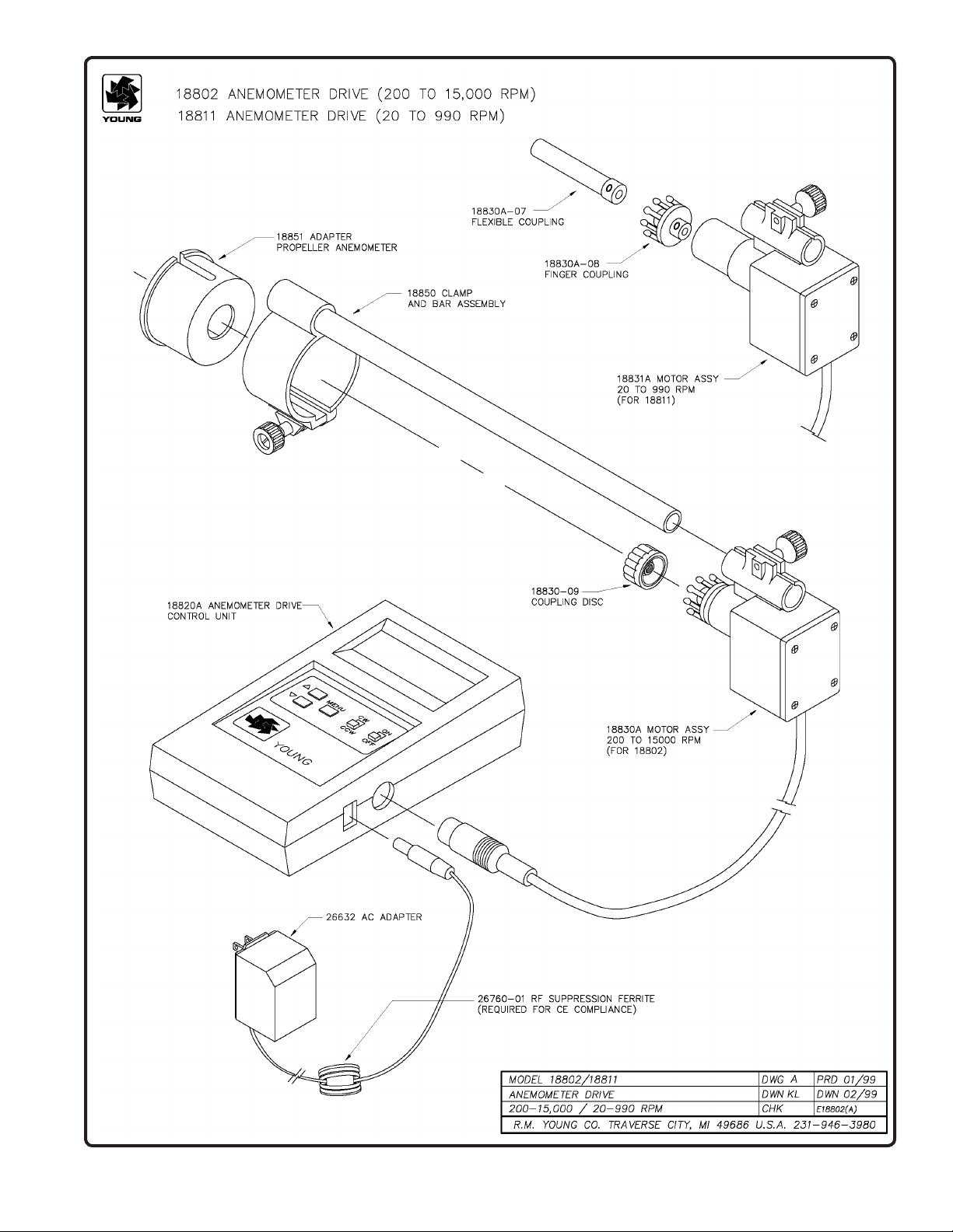
MODEL 18802/18811
SELECTABLE SPEED
ANEMOMETER DRIVE
SPECIFICATIONS
Operating Range: 200 - 15,000 RPM (18802)
20.0 - 990.0 RPM (18811)
Resolution: 1 RPM (18802)
0.1 RPM (18811)
Power Requirement: 12 to 30 VDC (2W n om in al , 6W
max)
Battery Power: Two 9-V
INTRODUCTION
The YOUNG S electable Speed Anemometer Drive provi des a
convenient and accurate way to rotate an anemometer shaft at a
known rate. The device consists of a control/display unit and a
variable speed motor with integral high-resolution optical encoder.
Two models are available: Model 18802 has an operating range
of 200 to 15,000 RPM for use with propeller type anemometers.
Model 18811 has a l ower RPM ra ng e for u se with cup ty pe
anemometers. The control unit is the same in each case. High and
low speed motors are available separately, permitting operation in
both speed ranges with a single display unit.
The control u ni t automatica ll y senses mo to r a ssembly ty pe
(high or low speed) and adjusts display and controlling circuits
automatically. Operating parameters for each motor type include
MAX & MIN RPM, STEP SIZE, and 9 PRESET speeds. Settings
for these parameters are saved when power is off.
A front panel CW-CCW switch selects rotation direction (as seen
facing anemometer). Motor speed is selected using the UP-DOWN
keys. Th e display s hows th e targe t and actua l RPM. Motor
rotation and measurement are referenced to a crystal oscillator for
stability and accuracy. Current limiting circuits protect the motor
from damage due to overload or stalling.
OPERATION
For proper o peration, the coupling on the motor must be
carefully aligned with the anemometer shaft. Misalignment,
particularly at low RPM rates, causes instability and stalling.
Alignment xtures included with the device allow the motor to be
attached directly to YOUNG anemometers. Attach the alignment
xture to the sensor as follows:
1) Remove propeller or cup-wheel from anemometer shaft and
attach coupling disc to shaft.
2) Mount clamp and bar xture on sensor and gently tighten
clamp. Do not overtighten!
3) Attach motor to xture. Carefully align anemometer and
motor coupling and gently tighten motor clamp. DO NOT
OVERTIGHTEN.
4) Turn unit ON and use the UP-DOWN keys to set target RPM.
5) Within several seconds display should show actual RPM
within ± 1 RPM of target setting. If not, carefully adjust
alignment until display shows proper value. This can be
performed while motor is running.
If the calibrating unit is used with an anemometer which does not
t the alignment xture, the motor may be held in place by hand.
Good results can be achieved if the motor and anemometer shafts
are well aligned.
MENU
Access the Setup Menu by pressing and holding the MENU key
for about five seconds. The motor will stop and the Setup Menu
will appear on the display. Each menu item and its function is listed
below.
Use the UP-DOWN keys to scroll between items on the menu list.
To EDIT a value, press the MENU key then use the UP-DOWN
keys to change it. When you are finished editing, press MENU
again. To return to O PERATE mode, repeatedly press th e UP
key until OPERATE appears on the display then press MENU.
The 18802 stores the new settings and within several seconds
will begin operating at its lowest speed. You MUST return to
OPERATE mode to retain new settings.
MENU ITEM DESCRIPTION
OPERATE Press MENU to return to OPERATE mode.
You MUS T ret urn t o OPE RATE
mode to retain new settings.
MAX RPM Max im um RP M allowed during opera ti on .
Once the maximum is reached, pressing the
UP ke y has no effec t. Limited to operatin g
range of motor.
MIN RPM Mi ni mum RPM a ll owed d ur in g oper at io n.
Once the minimum is reached, pressing the
DOWN key has no effect. Limited to operating
range of motor.
STEP SIZE The number of RP M a dd ed or subtracte d
when the UP- DO WN key s are pre ss ed to
change target RPM during operation.
PRESET YES/NO determines whether preset
RPM sett in gs are us ed. If YES, p ressing
the UP-DOWN keys selects preset speeds 1
through 9. If NO, UP-DOWN changes speed
by STEP SIZE increments.
The 18802 is powered from an AC wall adapter (included). For
completely portable operation, two internal 9-V batteries power the
unit. Use lithium type for longest life. When batteries are low, the
controller stops the motor and alerts the user on the display.
Page 5
PRESET1-9 Preset RPM values. Each PRESET may be
set to any value in operating range of motor.
18860-90
Page 7

WARRANTY
This product is warranted to be free of defects in materials and
construction for a period of 12 months from date of initial purchase.
Liability is limited to repair or replacement of defective item. A copy
of the warranty policy may be obtained from R. M. Young Company.
CE COMPLIANCE
This product has been tested and shown to comply with European
CE requirements for the EMC Directive.
Declaration of Conformity
R. M. Young Company
2801 Aero Park Drive
Traverse City, MI 49686 USA
Model 18802 ANEMOMETER DRIVE
The undersigned hereby declares on behalf of R. M.
Young Company that the above-referenced product, to
which this declaration relates, is in conformity with the
provisions of:
Council Directive 2004/108/EC (December 15, 2004)
on Electromagnetic Compatibility
David Poinsett
R&D Manager
18860-90
Page 6
Page 8
Page 7
18860-90
Page 9

18860-90
Page 8
Page 10

R. M. YOUNG COMPANY
TYPICAL TORQUE VALUES
For Checking Anemometer Bearing and Transducer Condition
threshold of:
Instrument (Standard Models) Sensor Transducer Torque Threshold 0.5 m/s 1.0 m/s
gm-cm m/s gm-cm gm-cm
03101-5 Wind Sentry Anemometer 03110 AC Coil 0.3 0.5 0.3 1.0
05103 Wind Monitor 08234 AC Coil 2.4 1.0 2.6
05106 Wind Monitor - MA 08234 AC Coil 2.9 1.1
05305 Wind Monitor - AQ 08254 AC Coil 0.3 0.3 1.0 3.8
05701 Wind Monitor - RE 08274 AC Coil 0.3 0.2 1.3 5.0
09101 Wind Monitor - SE 08234 AC Coil 2.4 1.0 2.6
09305 Wind Monitor - AQ - SE 08254 AC Coil 0.3 0.3 1.0 3.8
12102 Cup Anemometer 12170C 2400 mV Tach-Gen 0.4 0.5 0.4 1.4
12102D Cup Anemometer 12170C Photo Chopper 0.1 0.3 0.4 1.4
27106 Propeller Anemometer 08274 500 mV Tach-Gen 0.5 0.3 1.3 5.0
1
New Instrument
2
Max torque for
27106T Propeller Anemometer 08254 500 mV Tach-Gen 0.5 0.4 1.0 3.8
08274 Photo Chopper 0.3 0.2 1.3 5.0
NOTES:
1. New instrument torque and threshold specications are maximum values
2. Values shown are maximum torque to maintain instrument threshold at or below 0.5 m/s and 1.0 m/s respectively.
3. EPA and NRC instrument specications designate 0.5 m/s wind speed starting threshold. ASTM D5096-90 "Standard
Test Method for Determining the Performance of a Cup Anemometer or Propeller Anemometer" denes "starting
threshold" and outlines a method for its determination.
SENSORS:
03110 Wind Sentry 75 cm Cup Wheel Assembly
08234 18 X 30 cm Polypropylene Propeller (PP)
08254 20 X 30 cm Carbon Fiber Thermoplastic Propeller (CFT)
08274 22 X 30 cm Expanded Polystyrene Propeller (EPS)
12170C 100 cm Cup Wheel Assembly
STANDARD BEARINGS:
Model 05103 Wind Monitor / 09101 Wind Monitor-SE : Double Teon seals & lubricated with M-28 low torque grease
Model 05106 Wind Monitor - MA : Double Teon seals & lubricated with "Sta-lube" waterproof grease.
All other models : Double metal shields & lubricated with LOI instrument oil
Page 9
18860-90
Page 11

18860-90
Page 10
Page 12

Page 11
18860-90
Page 13

R. M. YOUNG COMPANY
TYPICAL TORQUE VALUES
For Checking Anemometer Bearing and Transducer Condition
Instrument (Standard Models) Torque Threshold 0.5 m/s @ 10° 1.0 m/s @ 10°
gm-cm m/s @ 10° gm-cm gm-cm
05103 Wind Monitor 30 1.1
05106 Wind Monitor - MA 30 1.1
05305 Wind Monitor - AQ 9 0.5 11 40
05701 Wind Monitor - RE 7 0.4 11 40
09101 Wind Monitor - SE 30 1.1
09305 Wind Monitor - AQ - SE 9 0.5 11 40
12302/5 Microvane 11 0.4 18 66
1
New Instrument
2, 3
Max torque for threshold of:
NOTES:
1. New instrument torque and threshold specications are maximum values
2. Values shown are maximum torque permitted to maintain instrument threshold at or below 0.5 m/s and 1.0 m/s
respectively at 10° displacement.
3. EPA and NRC instrument specications designate windvane threshold measurement at 10° displacement from
equilibrium position. ASTM D5366-93 “Standard Test Method for Determining the Dynamic Performance of a Wind
Vane” denes “starting threshold” and outlines a method for its determination.
STANDARD BEARINGS:
Models 05103 Wind Monitor / 05106 Wind Monitor-MA / 09101 Wind Monitor-SE:
Double Teon seals lubricated with LY-48 wide temperature range grease
Models 05305 Wind Monitor-AQ / 05701 Wind Monitor-RE / 09305 Wind Monitor-AQ-SE:
Double metal shields lubricateD with LOI instrument oil
All other models - Double Teon seals lubricated with LOI instrument oil
18860-90
Page 12
Page 14

Page 13
18860-90
Page 15

18860-90
Page 14
Page 16

Page 15
18860-90
 Loading...