Young 06201 User Manual

METEOROLOGICAL INSTRUMENTS
INSTRUCTIONS
WIND TRACKER
MODEL 06201
R.M. YOUNG COMPANY 2801 AERO PARK DRIVE, TRAVERSE CITY, MICHIGAN 49686, USA TEL: (231) 946-3980 FAX: (231) 946-4772 WEB: www.youngusa.com
PN: 06201-90
REV: I042814

MODEL 06201
WIND TRACKER
INTRODUCTION
TheYOUNG Model 06201 WindTracker is a compact wind speed and direction display with advanced features for use in a wide range of applications.
FEATURES
•3-digit wind speed display
•3-digit maximum wind speed or wind direction display
•Multi-color wind direction display with variability
•Wind speed and direction alarms with delay
•RS-485 serial connections
•Calibrated 0-5 VDC outputs
•Display brightness control
•Compatible with YOUNG wind sensors & 4-20 mA inputs
PRECAUTIONS
•INDOOR USE ONLYunless placed in approved enclosure
•Operatingtemperaturerange0-50°C(32-122°F),0-95%RH
•Useonlyrecommendedpowersources.12-30VDC,3.5W
•Disconnect power when connecting or servicing
•Alarm contact rating 24 VAC/30 VDC, 5 A resistive, 2 A inductive maximum
FACTORY DEFAULT SETTINGS
INPUT:
-Sensor Input Setting: "05" Wind Monitor
-Input selector switch position: "Down" (Sensor)
OPTIONS:
-Averaging: "No"
-Right hand display window: "Max Wind Speed"
-Alarms: "No"
OUTPUT:
- Voltage Outputs: 0-5Vdc=0-100m/s / 0-5Vdc = 0-360°
- Serial Output Type: "Binary"
IMPORTANT NOTE!:
Before connecting any external devices, verify the above settings are compatible with your application. If different, refer to the wiring diagrams for the correct settings.
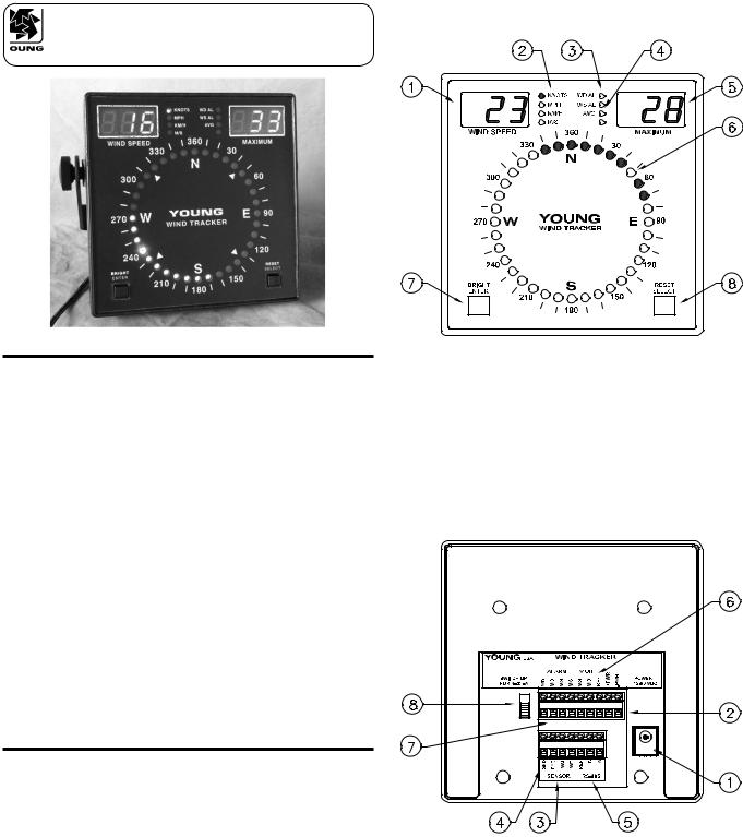
FRONT PANEL
1.Wind speed display
2.Wind speed units indicator
3.Alarm status indicators
4.Data averaging indicator
5.Maximum wind speed or direction display
6.Wind direction and variability display
7.Brightness control (operate) or Enter key (setup)
8.Maximum Reset (operate) or Select (setup)
BACK PANEL
1.Power input coaxial jack (12-30 VDC)
2.Power input terminals (12-30 VDC)
3.Sensor or 4-20 mA inputs
4.Earth ground connection
5.RS-485 serial input/output
6.0-5 VDC calibrated outputs
7.Alarm relay connections (Normally Open)
8.Input Selector Switch (Sensor or 4-20mA)
Page 1 |
06201-90(I) |

MOUNTING AND START-UP
1.For best visibility, place the Wind Tracker in a location free of direct sunlight. Mount it using the attached bracket or remove bracketforflushmountingtoabulkheadorpanelcutout.Panel cutout dimensions are given in the specifications.An optional rack mounting panel (Model 06280) and protective enclosure (Model 06260) are available from your YOUNG supplier.
2.Connect cables to terminals according to wiring diagram.
IMPORTANT NOTE! Please observe correct position of back-panel Input Selector Switch according to wiring diagram.
3.Connect GND terminal to suitable earth ground.
4.Insert power supply plug into power jack, plug power supply into a suitable AC wall outlet or connect to suitable 12 to 30 VDC power source to terminals.
IMPORTANT NOTE! Do not connect more than one power source to the Wind Tracker at the same time.
5.Whenpowerisapplied,theWindTrackerwilldisplayfirmware version number then begin to display wind information as follows:
•Wind speed
•Wind speed units
•Maximum wind speed or direction degrees
•Wind direction (single orange indicator)
•Direction variability (green indicators)
•Alarm status indicators (if selected)
•Wind speed & direction averaging indicator (if selected)
6.Observe display to confirm proper operation.
CHANGING SETTINGS
WindTrackerparametersmaybeinspectedorchangedinSETUP mode which is enabled by simultaneously pressing both ENTER and SELECT keys for about 4 seconds. When SETUP mode is active, abbreviations identify each function and available options as listed below. The SELECT key changes options or values. The ENTER key saves and moves to the next parameter.
Appearanceofoptionsdependsonparametersettings.Some options may be hidden.
DISPLAY |
SETUP FUNCTION |
|
InP |
03 |
Input / Sensor Type |
Wind Sentry |
||
|
04 |
Wind Monitor-Jr |
|
05 |
Wind Monitor |
|
05A |
Wind Monitor-AQ |
|
09 |
Wind Monitor-SE or YOUNG sonic anemometer |
|
SEr |
Serial input when used as remote display |
|
Ld2 |
Line Driver 4-20mA input (0-100 m/s) |
|
Hd |
Wind Monitor HD |
|
Ldi |
Line Driver 4-20mA input (0-50 m/s) |
SPd |
unt |
Wind Speed Units (annunciator blinks) |
SELECT key changes units. ENTER to save |
||
dSP |
no |
Display Averaging (annunciator blinks) |
Instantaneous data displayed |
||
|
YES |
Average data displayed |
PEr |
030 |
Set averaging period in seconds (0-999). |
|
|
Display will update at this interval. |
dSP |
SPd |
Right Display Window Selection |
Maximum wind speed |
||
|
dir |
Wind Direction degrees |
ALr |
no |
Wind Direction Alarm (annunciator blinks) |
Direction alarm not armed |
||
|
YES |
Direction alarm armed |
ALr |
dir |
SELECT key sets direction alarm sector start. |
ALr |
SPn |
ENTER key saves. |
SELECT key sets direction alarm sector span. |
||
|
|
ENTER key saves. |
ALr |
no |
Wind Speed Alarm (annunciator blinks) |
Speed alarm not armed |
||
|
YES |
Speed alarm armed |
ALr |
000 |
Alarm set-point. SELECT key increments value. |
|
|
ENTER key saves. |
dLY |
030 |
Alarm Delay Time |
Alarm delay time in seconds (0-999). SELECT key |
||
|
|
increments value. ENTER key saves. |
Snd |
no |
Sound |
No sound |
||
|
YES |
Audible beep with alarm activations or average |
|
|
update. |
dir |
360 |
Wind Direction Voltage Output Scale |
0-360 degrees |
||
|
540 |
0-540 degrees |
Out |
bin |
Serial Output Type |
Binary output for remote Wind Tracker displays |
||
|
ASC |
ASCII text wind speed & direction |
tSt |
no |
Test Functions |
No test |
||
|
YES |
Test |
tSt |
ALr |
SELECT key closes alarm relays. |
CAL |
0.00 |
SELECT key alternates between 0.00 and |
tSt |
dsP |
5.00 VDC output to calibrate external devices. |
SELECT key tests display sections. |
OPERATION
ALARMS
Wind speed and direction alarms each have their own set-point, LEDstatusindicator,andrelaycontacts.TheAlarmDelayparameter establishes time duration in or out of the set-point range needed for the alarm to change state. Front panel LEDs indicate alarm status during operation.
LED Off |
= |
Alarm not armed and OFF. Relay open |
LED Steady |
= |
Alarm armed and OFF. Relay open |
LED Blinking = |
Alarm armed and ON. Relay closed. |
|
|
|
Audible beep if Sound parameter is enabled. |
06201-90(I) |
Page 2 |
 Loading...