

Page 1
METEOROLOGICAL INSTRUMENTS
INSTRUCTIONS
COMPACT ASPIRATED
RADIATION SHIELD
MODEL 43502
R.M. YOUNG COMPANY 2801 AERO PARK DRIVE, TRAVERSE CITY, MICHIGAN 49686, USA
TEL: (231) 946-3980 FAX: (231) 946-4772 WEB: www.youngusa.com
43502-90(C)
REV: C062309
Page 2
MODEL 43502-90
COMPACT ASPIRATED
RADIATION SHIELD
INTRODUCTION
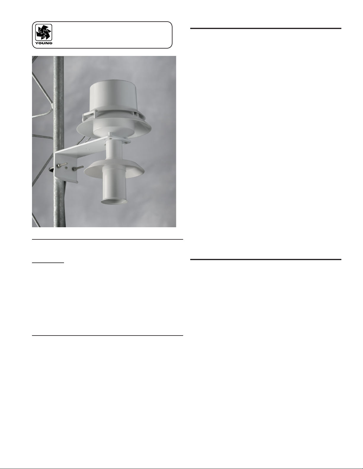
Model 43502 Aspirated Radiation Shield provides accurate ambient
air temperature measurements in a unique low cost, small size, and
conservatively rated instrument. Radiation errors are less than 0.2°
C RMS with the shield exposed to solar radiation of 1000 W/m2. The
triple wall shield employs three concentric downward facing intake
tubes and a canopy shade to isolate the temperature sensor from direct
and indirect radiation. The temperature sensor mounts vertically in the
center of the intake tubes.
Model 41342 Temperature Probe and Model 41382 RH/Temperature
Probe t directly in a mounting ring within the shield. The convenient
Model 41390 Junction Box, which is available separately, will accept
other RTD, thermocouple, or thermistor type sensors with sheath
diameters up to 10 mm (0.4 in) and 150 mm (6.0 in) in length. Other
types of sensors up to 20 mm diameter can also be accommodated in
the shield. Longer probes may be used with the optional Model 43476
Extender Tube.
The small shield size reduces the surface area exposed to incoming
radiation during the day, signicantly reducing the amount of heat that
needs to be washed away from the intake tubes. Errors from outgoing
radiation at night are similarly reduced. A continuous duty brushless
DC blower pulls ambient air into the shield and across the temperature
sensor. Flow rate at the sensor is 5 to 11 m/s, depending upon sensor
size. Brush-less electronic commutation of the blower motor is achieved
using dependable solid-state circuitry. The blower is designed for
continuous duty of more than 80,000 hours (9 years) at 25° C (77° F).
The blower housing and shield assembly are made from white UV
stable plastic, which provides high reectivity, low heat conduction, and
maximum weatherability. The mounting bracket with a plastic v-block
and stainless steel U-bolt will accommodate a vertical mounting post of
25 to 50 mm (1 to 2 in) diameter and allows easy height adjustment.
SPECIFICATIONS:
Sensor Types: Accomodates temperature and humidity sensors up
to 24mm (0.9 in) diameter
Radiation Error
Ambient Temp: <0.2°C (0.4°F) RMS (@1000 W/m² intensity)
Delta T: <0.05°C (0.1°F) RMS with like shields equally
exposed
Aspriation Rate: 5 to 11 m/s (16-36 fps) depending on sensor size
Power Reqmt: 12-14 VDC@500 mA for blower
Operating -50° to +60° C. (-58° to +140° F.)
Temperature
Range
DIMENSIONS
Overall Height: 33 cm (13 in)
Overall Diameter: 20 cm (8 in)
Shield: 7 cm (2.7 in) dia. x 12 cm (4.7 in)
Blower Housing: 17 cm (6.7 in) dia. x 11 cm (4.3 in)
Mounting: V-Block and U-Bolt for vertical post or tower member
25-50 mm (1.0-2.0 in) dia.
The Model 43502 is ideally suited for lapse rate measurements. With
identical shields and sensors at 2 m and 10 m levels, the temperature
difference (delta T) can be measured with a relative accuracy of 0.05° C
RMS under conditions of maximum solar radiation.
EXPOSURE
The ideal shield location is over dry, at terrain with a grass surface.
Avoid locations near large buildings, paved areas, rooftops, tunnels,
or other structures, which may exhaust warm air or radiate heat. Give
careful consideration to the effects of lakes or ponds which can modify
air temperature dramatically, low areas that hold standing water after
rains, sheltered hollows, high vegetation, and steep slopes and valleys
which are subject to air drainage from remote locations.
As a general rule, locate the shield downwind at a distance at least four
times the height of any nearby obstructions and at least 30 m (100 ft)
from paved areas.
Mount the shield on a tower or other supporting structure on the side of
the prevailing wind or direction of primary interest. This will reduce the
chance for errors introduced by air warmed by the supporting structure
itself.
For more detailed information about siting refer to the Quality
Assurance Handbook for Air Pollution Measurement Systems, Volume
IV - Meteorological Measurements (U.S. Environmental Protection
Agency, Atmospheric Research and Exposure Assessment Laboratory,
Research Triangle Park, NC 27711).
Page 1
43502-90(C)
Page 3

INITIAL CHECKOUT
MAINTENANCE
The mounting bracket attaches to a vertical mounting post up to 5 cm (2
in) in diameter. The mounting post should be of sufcient length to allow
the shield intake to be adjusted to the desired height above the ground.
Tighten the U-bolt sufciently for a secure hold without distorting the
plastic v-block.
See the accompanying section view drawings for reference to names
and locations of shield components and position of sensor within the
shield. The tip of the sensor should be positioned 60mm (2.4 in) to
90mm (3.5 in) from the shield intake. The blower cover is hinged to
allow easy access for sensor installation and cable connections. Loosen
the captive screw in the blower cover to open.
The standard Model 43502 Aspirated Radiation Shield is supplied with
a mounting bushing which ts YOUNG sensors. An additional blank
bushing is also supplied which can be drilled to t sensors up to 20 mm
(0.8 in.) diameter. YOUNG Temperature Probes and Relative Humidity/
Temperature Probes are supplied with a junction box and cable
bushing. The junction box provides terminals for cable connections and
properly positions the sensor within the shield assembly.
Temperature sensors from other suppliers can also be used with the
Model 41390 Junction Box, which is available separately. It can be
drilled to t sensor diameters up to 10 mm (0.4 in). For the sensor to
be properly positioned when the junction box is placed in the shield,
mount the sensor so its tip projects approximately 60 mm (2.4 in.)
beyond the end of the junction box. For temperature probes too long
to meet this requirement, use the optional Model 43476 Extender Tube
to increase the distance between the shield assembly and the blower
assembly. When installing the shield assembly in the blower assembly
hand tighten only being very careful to avoid cross-threading or over
tightening.
CONNECTIONS
Depending on conditions, the blower should provide trouble-free
operation for several years. It is designed for continuous duty life of
80,000 hours at 25 C°. Blower life is somewhat reduced at higher
temperature but it will perform satisfactorily at temperatures as high as
70 C°. The blower assembly is easily replaced if necessary. Remove
the printed circuit card from the blower cover and unsolder the blower
leads. Loosen the two screws inside the blower cover which secure the
inside chamber and blower to the outside cover. Install the replacement
blower in the exact same orientation (with the blower exhaust opposite
the printed circuit card). Re-solder the blower leads to the printed circuit
card. Be sure to observe correct polarity when reconnecting the blower
leads (red – POS, black - NEG).
Inspect and clean the shield at regular intervals to maintain optimum
performance. When the shield becomes dirty wash it thoroughly inside
and out with mild soap and warm water. If necessary, use alcohol to
remove any oil lm. Do not use any other type of solvent.
Check the mounting bolt and cable clamps periodically to for possible
loosening from vibration.
WARRANTY
This product is warranted to be free of defects in materials and construction
for a period of 12 months from date of initial purchase. Liability is limited
to repair or replacement of defective item. A copy of the warranty policy
may be obtained from R. M. Young Company.
CE COMPLIANCE
This product has been tested and shown to comply with European CE
requirements for the EMC Directive (see Declaration of Conformity
below). Please note that shielded cable must be used.
With the blower cover open connect blower power (12-14 VDC unless
otherwise noted) to the terminals on the underside of the cover.
Terminal designations positive (POS), negative (NEG), and optional
tachometer (TACH), are marked on the printed circuit board. Blower
power is normally provided by the plug-in power supply adapter
included. BE SURE TO OBSERVE CORRECT POLARITY. Red is
positive, black is negative. The blower motor draws approximately
420mA-480mA. Use sufciently heavy gauge wire between the power
supply adapter and the blower motor terminals to avoid signicant
voltage drop. Clamp the blower power cable with the cable clamp
provided at the edge of the printed circuit card. When tying the cable
to the mounting structure provide a sufcient loop in the cable to allow
the blower cover to be opened and closed easily. Transient protection is
provided on the printed circuit card and in the blower motor.
Unthread and remove the cover from the sensor junction box. Insert
the sensor cable through the packing nut in the side of the junction box.
Attach sensor conductors to the appropriate terminals on the circuit
card inside and replace the junction box cover. The sensor cable exits
the side of the blower housing at the notches provided using the black
grommet to provide a seal. Clamp the cable to the lower ange of the
housing to keep it in proper position when the cover is closed.
Declaration of Conformity
R. M. Young Company
2801 Aero Park Drive
Traverse City, MI 49686 USA
Model 43502 Compact Aspirated Radiation Shield.
The undersigned hereby declares on behalf of R. M.
Young Company that the above-referenced product, to
which this declaration relates, is in conformity with the
provisions of:
Council Directive 2004/108/EC (December 15, 2004)
on Electromagnetic Compatibility
David Poinsett
R&D Manager
43502-90(C)
Page 2
Page 4

TTL 5V
1 PULSE
PRD
JMT
B
11/08
11/08
SECTION VIEW
MODEL 43502 ASPIRATED RADIATION SHIELD
DWN
CHK
DWG
R.M. YOUNG CO. TRAVERSE CITY, MI 49686 U.S.A. 231−946−3980
DWN
41382 TEMP/RH PROBE CONFIGURATION
43502 with 41382 TEMP/RH PROBE
S43502(pg3)(B)
43530 SHIELD ASSEMBLY
PULSED OUTPUT
41382 TEMP/RH PROBE
43447−04 12VDC BLOWER WITH
P.C. BOARD
BLOWER CABLE CLAMP
SENSOR CABLE CLAMP
43532 MOTOR CONNECTION
43534 SENSOR MTG BUSHING
TEMP OR
TEMP R.H. SENSOR
BLK RED
TACHOMETER OUTPUT
BLOWER MOTOR
12−14 VDC @ 500MA
BLOWER POWER
LOGGER
TO DATA
RUBBER FLANGE
BUSHING
NEG
MODEL 43447−04
BLOWER MOTOR
RED
BLU/WHT
BLK
12−14 VDC
TACHOMETER OUTPUT
REF
TACH OUT
POS
(2 PULSES/REV)
*Max set screw torque 80 oz-in
Page 3
43502-90(C)
Page 5

41390 J−BOX CONFIG
43502 with 41390 JUNCTION BOX and PROBE
43536 BLANK BUSHING
(NOT SHOWN)
S43502(pg4)(B)
43476
EXTENDER TUBE
41390 JUNCTION BOX
(ACCOMODATES SENSORS UP
TO 10mm (0.4in) DIAMETER)
JMT
B
11/08
11/08
SECTION VIEW
MODEL 43502 ASPIRATED RADIATION SHIELD
DWN
CHK
DWG
R.M. YOUNG CO. TRAVERSE CITY, MI 49686 U.S.A. 231−946−3980
PRD
DWN
43502-90(C)
Page 4
 Loading...