

Page 1
METEOROLOGICAL INSTRUMENTS
INSTRUCTIONS
WIND MONITOR
INTRINSICALLY SAFE WITH 4-20mA OUTPUTS
MODEL 05501LM
R.M. YOUNG COMPANY 2801 AERO PARK DRIVE, TRAVERSE CITY, MICHIGAN 49686, USA
TEL: (231) 946-3980 FAX: (231) 946-4772 WEB: www.youngusa.com
P/N: 05501-90
REV: D102811
Page 2
MODEL 05501LM
WIND MONITOR
Intrinsically Safe with 4-20 mA Outputs
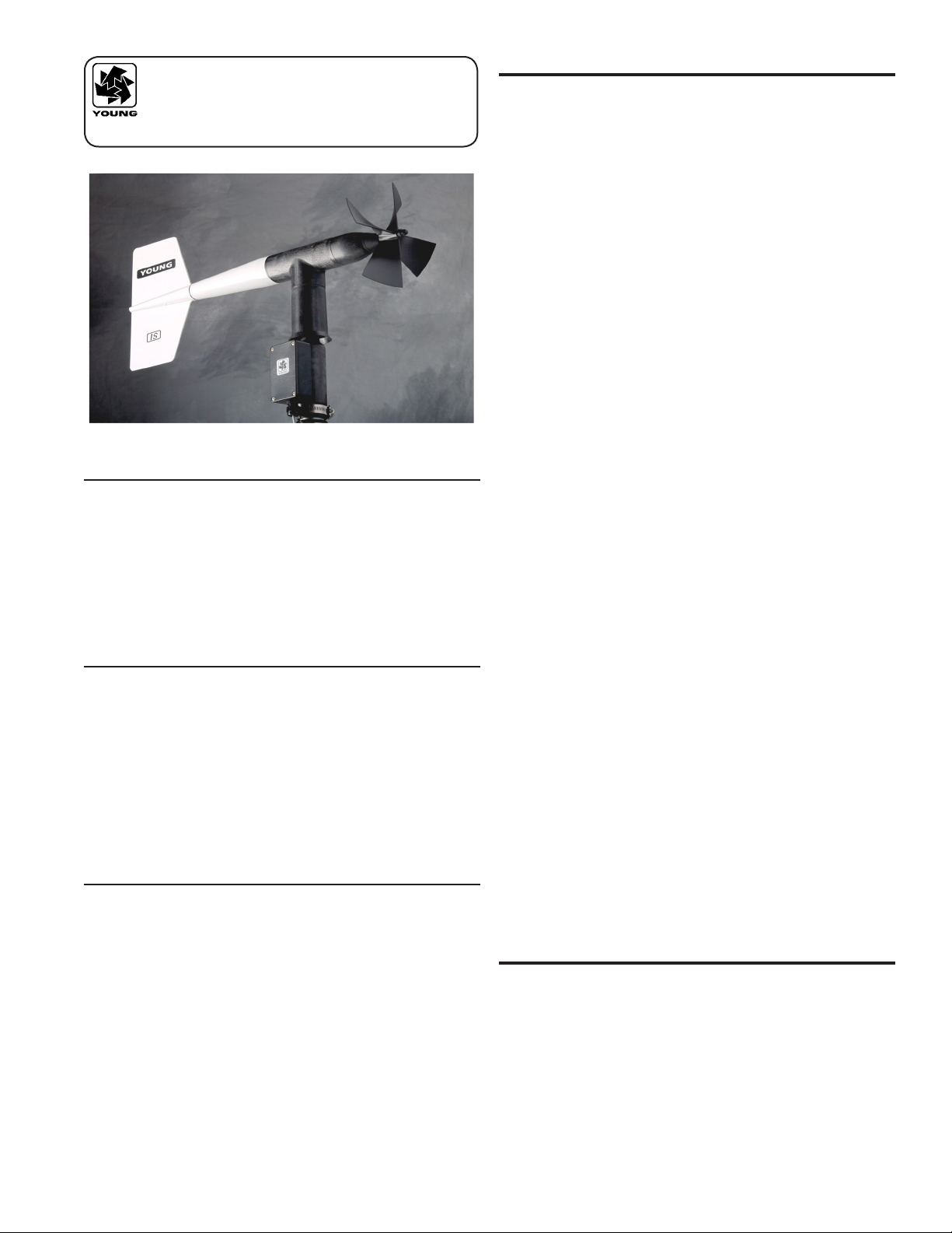
INTRODUCTION
Model 05501LM Wind Monitor IS is an intrinsically safe wind sensor
that converts horizontal wind speed and direction measurements to
calibrated 4-20 mA signals. Each signal is derived from independent
2-wire loop-powered circuits. The sensor operates over a wide
ambient temperature range.
Intrinsic safety is achieved when the sensor is used with approved
barriers. Intrinsically safe systems are recognized as practical
and effective means of operating instruments in an explosive
environment. The technique limits the amount of energy available to
ignite explosive gases or ignitable mixtures. This is accomplished by
controlling the amount of voltage and current in the hazardous area.
When used with an approved Intrinsically Safe barrier, the Wind
Monitor IS can be used in Class 1, Division 1, Group A,B,C,D
hazardous areas. The categories are dened as follows:
WIND SPEED SPECIFICATION SUMMARY
Operating Range 0 to 60 m/s (134 mph)
Gust Survival 100 m/s (220 mph)
Sensor Type 18 cm diameter 4-blade helicoid
polypropylene propeller, 29.4 cm air
passage per revolution
Distance Constant 2.7 m (8.9 ft.) for 63% recovery
Threshold Sensitivity 1.0 m/s (2.2 mph)
Output Signal 4-20 mA for 0 to 50 m/s (100 m/s optional)
Power Requirement: 10 to 30 VDC at 20 mA max
WIND DIRECTION (AZIMUTH) SPECIFICATION SUMMARY
Range 360° mechanical,
355° electrical (5° open)
Sensor Balanced vane,
38 cm (15 in) turning radius.
Damping Ratio 0.3
Delay Distance 1.3 m (4.3 ft) for 50% recovery
Threshold Sensitivity 1.1 m/s (2.4 mph) at 10° displacement
Natural Wavelength 7.4 m (24.3 ft) Damped
7.2 m (23.6 ft) Undamped
Output Signal 4-20 mA for 0 to 360°
Power Requirement: 10 to 30 VDC at 20 mA max
GENERAL
Ambient Temperature -50 to 50°C (-58 to 122°F)
Intrinsic Safety Class I, Division 1, Groups A, B, C, D
when installed with approved
Intrinsically Safe Barrier
(see Wiring Diagram)
Entity Approval Vmax = 30V
Imax = 100 mA
Ci = 0.01 uF
Li = 0.0 uH
Class I Locations in which ammable gases or vapors are or may
be present in quantities sufcient to produce explosive or
ignitable mixtures.
Division 1 Locations in which hazardous concentrations in the air
exist continuously, intermittently, or periodically under
normal operating conditions.
Group A Atmospheres containing acetylene
Group B Atmospheres containing hydrogen, or gases or vapors of
equivalent hazard, such as manufactured gas.
Group C Atmospheres containing ethyl-ether vapors, ethylene, or
cyclo-propane
Group D Atmospheres containing gasoline, hexane, naptha,
benzine, butane, propane, alcohol, acetone, benzol,
lacquer solvent vapors, or natural gas.
The Wind Monitor IS is rugged and corrosion resistant, yet accurate
and lightweight. Housing, nose cone, propeller, and other components
are injection molded with U.V. stabilized plastic. Both the propeller
and vertical shafts use stainless steel precision grade ball bearings.
Propeller rotation produces an AC sine wave signal with frequency
proportional to wind speed. Internal circuitry converts this signal to a
calibrated 4 to 20 mA current output.
Vane position is sensed by a 10K ohm precision conductive plastic
potentiometer. This signal is also converted to 4 to 20mA output.
The instrument mounts directly on a standard one inch pipe, outside
diameter 34 mm (1.34"). An orientation ring is provided so the
instrument can be removed for maintenance and re-installed without
loss of wind direction reference. Both sensor and orientation ring
are secured to the mounting pipe by stainless steel band clamps.
Electrical connections are made in a junction box at the base.
INITIAL CHECK-OUT
When the instrument is unpacked, check it carefully for signs of
shipping damage.
Page 1
05501LM-90(D)
Page 3

Remove the plastic nut on the propeller shaft. Install the propeller on
×+=
360
164
angle
mA
4
360
355
168.19 +
×≈
the shaft with the serial number of the propeller facing forward (into
the wind). The instrument is aligned, balanced and fully calibrated
before shipment; however, it should be checked both mechanically
and electrically before installation. The vane and propeller should
easily rotate 360° without friction. Check vane balance by holding
the instrument base so the vane surface is horizontal. It should have
near neutral torque without any particular tendency to rotate. A slight
imbalance will not degrade performance.
INSTALLATION
PROPER ELECTRICAL CONNECTION IS CRITICAL
FOR SAFE USE IN HAZARDOUS LOCATIONS.
FAILURE TO DO SO COULD RESULT IN INJURY TO PERSONS
OR PROPERTY DAMAGE.
AN APPROVED INSTRINSICALLY SAFE BARRIER
MUST BE USED.
REFER TO WIRING DIAGRAM FOR CONNECTION DETAILS.
FOLLOW BARRIER MANUFACTURER'S GUIDELINES FOR
CORRECT INSTALLATION.
OBSERVE NEC CODES FOR WIRING IN HAZARDOUS
LOCATIONS OR EQUIVALENT.
The Wind Monitor IS must be connected through an approved
Intrinsically Safe barrier or its equivalent. Examples of approved
barriers include the following models from MTL (www.mtl-inst.com):
MTL 7087+ Passive diode barrier with resistors
MTL 7106 Diode barrier with active electronics
MTL 7206 Diode barrier with active electronics
MTL 5041 Isolated barrier with active electronics
MTL 5044 2-ch version of MTL5041
Entity Parameters for the Wind Monitor IS are as follows:
Accurate wind measurements require proper instrument placement.
Eddies from trees, buildings, or other structures can greatly inuence
wind speed and direction observations. To get meaningful data for
most applications, locate the instrument well above or upwind from
obstructions. As a general rule, the air ow around a structure is
disturbed to twice the height of the structure upwind, six times the
height downwind, and up to twice the height of the structure above
ground. For some applications it may not be practical or necessary to
meet these requirements.
Initial installation is most easily done with two people; one to adjust
the instrument position and the other to observe the indicating device.
After initial installation, the instrument can be removed and returned
to its mounting without realigning the vane since the orientation ring
preserves the wind direction reference. Install the Wind Monitor
following these steps:
1. MOUNT WIND MONITOR
a) Place orientation ring on mounting post. Do Not tighten
band clamp yet. Orientation ring may be omitted when portable
tripod is used.
b) Place Wind Monitor on mounting post. Do Not tighten band
clamp yet.
2. CONNECT SENSOR CABLE.
a) Refer to diagram W05501L located at back of manual.
3. ALIGN VANE
a) Connect instrument to indicator.
b) Choose a known wind direction reference point on the
horizon.
c) Sighting down instrument centerline, point nose cone at
reference point on horizon.
d) While holding vane in position, slowly turn base until
indicator shows proper value.
e) Tighten mounting post band clamp.
f) Engage orientation ring indexing pin in notch at instrument
base.
g) Tighten orientation ring band clamp.
Vmax = 30 VDC
Imax = 100 mA
Li = 0.0 uH
Ci = 0.01 uF
Any approved barrier may be used provided that its specications and
the wiring connections fulll the following relationship:
Vmax > Voc
Imax > Isc
La > Li + Lw
Ca > Ci + Cw
Where:
Vmax = 30 VDC Max Open Circuit Voltage of 05501LM
Imax = 100 mA Max Short Circuit Current of 05501LM
Li = 0.0 uH Inductance of 05501LM
Ci = 0.01 uF Capacitance of 05501LM
Lw = Connecting Wire Inductance
Cw = Connecting Wire Capacitance
Voc = Maximum Open Circuit Voltage of IS Barrier
Isc = Maximum Short Circuit Current of IS Barrier
La = Maximum Allowed Inductance of IS Barrier
Ca = Maximum Allowed Capacitance of IS Barrier
CALIBRATION CHECK
The Wind Monitor IS is fully calibrated before shipment and should
require no adjustments. Periodic calibration checks are desirable and
may be necessary if the instrument is used in programs which require
auditing of sensor performance.
WIND DIRECTION
Place the instrument on a Young Model 18112 Vane Angle Bench
Stand. Connect the instrument to a signal conditioning circuit
which indicates wind direction. Move the vane to various angular
orientations on the Vane Angle Bench Stand and observe the Wind
Monitor output. Indicated vane angle should agree with actual angle
within ±3°. If measuring current output, use the following formula:
Note that while the sensor mechanically rotates through a full 360°,
the active region of the sensor ends at 355°. This means that the
highest obtainable reading occurs at 19.8 mA.
05501LM-90(D)
Page 2
Page 4

WIND SPEED
×+=50164
speed
mA
RPMspeed ×= 0049.0
Remove the propeller and connect a Young Model 18802 Anemometer
Drive to the propeller shaft. Connect the instrument to a signal
conditioning circuit indicating wind speed.
Set the Anemometer Drive to various rates and observe the Wind Monitor
output. Indicated speed should agree with actual speed within ±0.5 m/s.
Use the following formulas:
Speed is in meters per second (m/s).
3. REMOVE POTENTIOMETER
a) Loosen set screw on potentiometer coupling and remove it from
potentiometer adjust thumbwheel.
b) Loosen set screw on potentiometer adjust thumbwheel and
remove it from potentiometer shaft.
c) Loosen two set screws at base of transducer assembly and
remove assembly from vertical shaft.
d) Unscrew potentiometer housing from potentiometer mounting
& coil assembly.
e) Push potentiometer out of potentiometer mounting &
coil assembly by applying firm but gentle pressure on
potentiometer shaft. Make sure that the shaft o-ring comes out
with the potentiometer. If not, then gently push it out from the
top of the coil assembly.
Details on checking bearing torque, which affects wind speed and
direction threshold, appear in the following section.
MAINTENANCE
Given proper care, the Wind Monitor should provide years of
service. The only components likely to need replacement due to
normal wear are the precision ball bearings and the wind direction
potentiometer. Only a qualied instrument technician should perform
the replacement. If service facilities are not available, return the
instrument to the company. Refer to the drawings to become familiar
with part names and locations. The asterisk * which appears in
the following outlines is a reminder that maximum torque on all set
screws is 80 oz-in.
ELECTRONIC REPAIR MAY BE PERFORMED
ONLY BY QUALIFIED TECHNICIANS.
SUBSTITUTION OF COMPONENTS
MAY IMPAIR INTRINSIC SAFETY.
POTENTIOMETER REPLACEMENT
The potentiometer has a life expectancy of fty million revolutions.
As it becomes worn, the element may begin to produce noisy signals
or become non-linear. When signal noise or non-linearity becomes
unacceptable, replace the potentiometer. Refer to exploded view
drawing and proceed as follows:
1. REMOVE MAIN HOUSING
a) Unscrew nose cone from main housing. Set o-ring aside for
later use.
b) Remove 4 screws attaching housing.
c) Gently push main housing latch.
d) While pushing latch, lift main housing up and remove It from
vertical shaft bearing rotor.
2. UNSOLDER TRANSDUCER WIRE
a) Remove junction box cover, exposing circuit board.
b) Remove screws holding circuit board.
c) Unsolder three potentiometer wires (white, green, black), two
wind speed coil wires (red, black), and earth ground wire (red)
from board.
4. INSTALL NEW POTENTIOMETER
a) Push new potentiometer into potentiometer mounting & coil
assembly making sure o-ring is on shaft.
b) Feed potentiometer and coil wires through hole in bottom of
potentiometer housing.
c) Screw potentiometer housing onto potentiometer mounting &
coil assembly.
d) Gently pull transducer wires through bottom of potentiometer
housing to take up any slack. Apply a small amount of silicone
sealant around hole.
e) Install transducer assembly on vertical shaft allowing 0.5 mm
(0.020") clearance from vertical bearing. Tighten set screws* at
bottom of transducer assembly.
f) Place potentiometer adjust thumbwheel on potentiometer shaft
and tighten set screw*.
g) Place potentiometer coupling on potentiometer adjust
thumbwheel. Do Not tighten set screw yet.
5. RECONNECT TRANSDUCER WIRES
a) Using needle-nose pliers or a paper clip bent to form a small
hook, gently pull transducer wires through hole in junction box.
b) Solder wires to circuit board according to wiring diagram.
Observe color code.
c) Secure circuit board in junction box using two screws removed
in step 2b. Do not overtighten.
6. REPLACE MAIN HOUSING
a) Place main housing over vertical shaft bearing rotor. Be careful
to align indexing key and channel in these two assemblies.
b) Place main housing over vertical shaft bearing rotor until
potentiometer coupling is near top of main housing.
c) Turn potentiometer adjust thumbwheel until potentiometer
coupling is oriented to engage ridge in top of main housing.
Set screw on potentiometer coupling should be facing the front
opening.
d) With potentiometer coupling properly oriented, continue pushing
main housing onto vertical shaft bearing rotor until main
housing latch locks into position with a “click”.
7. ALIGN VANE
a) Connect excitation voltage and signal conditioning electronics
to terminal strip according to wiring diagram.
b) With mounting post held in position so junction box is facing
due south, orient vane to a known angular reference. Details
appear in CALIBRATION section.
c) Reach in through front of main housing and turn potentiometer
adjust thumbwheel until signal conditioning system indicates
proper value.
d) Tighten set screw* on potentiometer coupling.
*Max set screw torque 80 oz-in
8. REPLACE NOSE CONE
a) Screw nose cone into main housing until o-ring seal is
seated. Be certain threads are properly engaged to avoid crossthreading.
05501LM-90(D)
Page 3
Page 5

FLANGE BEARING REPLACEMENT
If anemometer bearings become noisy or wind speed threshold
increases above an acceptable level, bearings may need
replacement. Check anemometer bearing condition using a Model
18310 Propeller Torque Disc. If necessary, bearings are replaced as
follows.
1. REMOVE OLD BEARINGS
a) Unscrew nose cone. Set o-ring aside for later use.
b) Loosen set screw on magnet shaft collar and remove magnet.
c) Slide propeller shaft out of nose cone assembly.
d) Remove front bearing cap which covers front bearing.
e) Remove both front and rear bearings from nose cone assembly.
Insert edge of a pocket knife under bearing ange and lift it out.
2. INSTALL NEW BEARINGS
a) Insert new front and rear bearings into nose cone.
b) Replace front bearing cap.
c) Carefully slide propeller shaft thru bearings.
d) Place magnet on propeller shaft allowing 0.5 mm (0.020")
clearance from rear bearing.
e) Tighten set screw* on magnet shaft collar.
f) Screw nose cone into main housing until o-ring seal is seated.
Be certain threads are properly engaged to avoid cross-
threading.
VERTICAL SHAFT BEARING REPLACEMENT
Vertical shaft bearings are much larger than the anemometer
bearings. Ordinarily, these bearings will require replacement less
frequently than anemometer bearings. Check bearing condition using
a Model 18331 Vane Torque Gauge.
WARRANTY
This product is warranted to be free of defects in materials and construction
for a period of 12 months from date of initial purchase. Liability is limited
to repair or replacement of defective item. A copy of the warranty policy
may be obtained from R. M. Young Company.
CE COMPLIANCE
This product has been tested and shown to comply with European CE
requirements for the EMC Directive (see Declaration of Conformity
below). Please note that shielded cable must be used.
Declaration of Conformity
R. M. Young Company
2801 Aero Park Drive
Traverse City, MI 49686 USA
Model 05501LM
The undersigned hereby declares on behalf of R. M.
Young Company that the above-referenced product, to
which this declaration relates, is in conformity with the
provisions of:
Council Directive 2004/108/EC (December 15, 2004)
on Electromagnetic Compatibility
Since this procedure is similar to POTENTIOMETER REPLACEMENT,
only the major steps are listed here.
1. REMOVE MAIN HOUSING.
2. UNSOLDER TRANSDUCER WIRES AND REMOVE TRANSDUCER
ASSEMBLY. Loosen set screws at base of transducer assembly
and remove entire assembly from vertical shaft.
3. REMOVE VERTICAL SHAFT BEARING ROTOR by sliding it up-
ward off vertical shaft.
4. REMOVE OLD VERTICAL BEARINGS AND INSTALL NEW BEAR-
INGS. When inserting new bearings, be careful not to apply pressure to bearing shields.
5. REPLACE VERTICAL SHAFT BEARING ROTOR.
6. REPLACE TRANSDUCER & RECONNECT WIRES.
7. REPLACE MAIN HOUSING.
8. ALIGN VANE.
9. REPLACE NOSE CONE.
David Poinsett
R&D Manager
05501LM-90(D)
Page 4
Page 6

Page 5
05501LM-90(D)
Page 7

BEARING REPLACEMENT & POTENTIOMETER ADJUSTMENT
05501LM-90(D)
Page 6
Page 8

GENERAL ASSEMBLY & REPLACEMENT PARTS
Page 7
05501LM-90(D)
 Loading...