

Page 1

METEOROLOGICAL INSTRUMENTS
INSTRUCTIONS
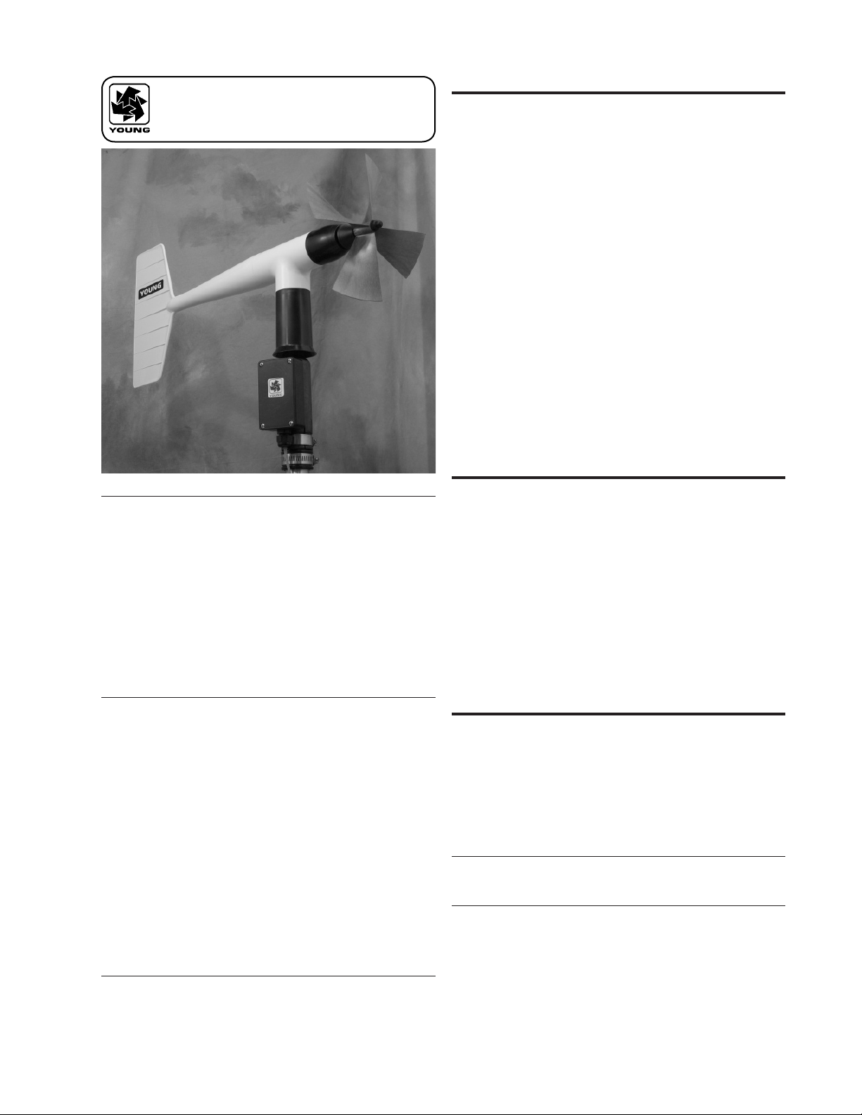
WIND MONITOR-AQ
WITH 4-20mA OUTPUTS
MODEL 05305L
R.M. YOUNG COMPANY 2801 AERO PARK DRIVE, TRAVERSE CITY, MICHIGAN 49686, USA
TEL: (231) 946-3980 FAX: (231) 946-4772 WEB: www.youngusa.com
P/N: 05305L-90
REV: G102811
Page 2
MODEL 05305L
WIND MONITOR-AQ
with 4-20mA OUTPUTS
WIND SPEED SPECIFICATION SUMMARY
Range 0 to 50 m/s (112 mph)
Sensor 20 cm diameter 4-blade helicoid carbon
ber thermoplastic propeller, 30.7 cm air
passage per revolution
Distance Constant 2.1 m (6.9 ft.) for 63% recovery
Threshold Sensitivity 0.4 m/s (0.9 mph)
Transducer Centrally mounted stationary coil,
2K Ohm nominal DC resistance
Output Signal 4 to 20 mA = 0 to 100 m/s
INTRODUCTION
The Wind Monitor measures horizontal wind speed and direction.
Developed for air quality applications, it is accurate, sensitive, and
corrosion resistant. The main housing, nose cone, propeller, and
other internal parts are injection molded U.V. stabilized plastic. The
tail section is lightweight expanded polystyrene. Both the propeller
an d vert ica l s haft s use st ain less s t eel prec i sio n g rad e b all
bearings. Bearings have shields to help exclude contamination
and moisture.
Propeller rotation produces an AC sine wave signal with frequency
proportional to w ind spee d. Internal circuitry converts the raw
signal to 4 to 20 mA current output over specified wind speed
range.
Vane position is sensed by a 10K ohm precision conductive plastic
potentiometer. This signal is also converted to 4 to 20mA output.
The instrum en t mounts dire ct ly on a st an dard one in ch pipe,
outside diameter 34 mm (1.34"). An orientation ring is provided so
the instrument can be removed for maintenance and re-installed
without loss of wind direction reference. Both the sensor and the
orientation ring are secured to the mounting pipe by stainless steel
band clamps. Electrical connections are made in a junction box at
the base.
INITIAL CHECK-OUT
When the Wind Monitor is unpacked it should be checked carefully
for any signs of shipping damage.
Remove the plastic nut on the propeller shaft. Install the propeller
on the shaft with the serial number of the propeller facing forward
(into the wind). The instrument is aligned, balanced and fully
calibrated before shipment; however, it should be checked both
mechanically and electrically before installation. The vane and
propeller should easily rotate 360° without friction. Check vane
balanc e by ho lding the in strumen t base so t he van e surface
is ho rizon tal. I t sh ou ld h ave ne ar n eutral torque witho ut any
particular tendency to rotate. A slight imbalance will not degrade
performance.
WIND DIRECTION (AZIMUTH) SPECIFICATION SUMMARY
Range 360° mechanical, 355° electrical (5° open)
Sensor Balanced vane, 48.3 cm (19 in) turning radius.
Damping Ratio 0.45
Delay Distance 1.2 m (3.9 ft) for 50% recovery
Threshold Sensitivity 0.5 m/s (1.0 mph) at 10° displacement
Damped Natural
Wavelength 4.9 m (16.1 ft)
Undamped Natural
Wavelength 4.4 m (14.4 ft)
Transducer Precision conductive plastic potentiometer,
10K ohm resistance (±20%), 0.25%
linearity, life expectancy 50 million
revolutions, rated 1 watt at 40°C, 0 watts
at 125°C
Output Signal 4 to 20 mA for 0 to 360°
GENERAL
Power Requirement: 12 - 30 VDC
Operating Temp: -50 to 50°C (-58 to 122°F)
Page 1
INSTALLATION
Proper placement of the instrument is very important. Eddies from
trees, buildings, or other structures can greatly influence wind
speed and wind direction observations. To get meaningful data for
most applications, locate the instrument well above or upwind from
obstructions. As a general rule, the air ow around a structure is
disturbed to twice the height of the structure upwind, six times the
height downwind, and up to twice the height of the structure above
ground. For some applications it may not be practical or necessary
to meet these requirements.
FAILURE TO PROPERLY GROUND THE WIND MONITOR
MAY RESULT IN ERRONEOUS SIGNALS
OR TRANSDUCER DAMAGE.
Grounding the Wind Monitor is vitally important. Without proper
grounding, static ele ctrical ch arge can build up during certain
atmospheric conditions and discharge through the transducers.
This discharge may cause erroneous signals or transducer failure.
To direct the discharge away from the transducers, the mounting
post assembly in which the transducers are mounted is made with
a special anti-static plastic. It is important that the mounting post
be connected to a good earth ground. There are two ways this
may be accomplished. First, the Wind Monitor may be mounted
05305L-90(G)
Page 3

on a metal pipe which is connected to earth ground. The mounting
pipe should not be painted where the Wind Monitor is mounted.
Towers or masts set in concrete should be connected to one or
more grounding rods. If it is difcult to ground the mounting post
in th is m anner, the follo wing method shoul d be use d. Ins ide
the jun ction bo x the screw labeled EART H GND i s intern ally
connected to the anti-static mounting post. This terminal should be
connected to an earth ground (Refer to wiring diagram).
Initial installation is most easily done with two people; one to adjust
the instrument position and the other to observe the indicating
device. After initial installation, the instrument can be removed
and returned to its mounting without re-aligning the vane since the
orientation ring preserves the wind direction reference. Install the
Wind Monitor following these steps:
Wind speed calibration is determined by propeller pitch and the
output characteri st ics of the transdu ce r. C al ibration formulas
showing wind speed vs. propeller rpm and output frequency are
included below. Standard accuracy is ± 0.2 m/s (0.4 mph). For
greater accuracy, the sensor must be individually calibrated in
comparison with a wind speed standard. Contact the factory or
your supplier to schedule a NIST (National Institute of Standards &
Technology) traceable wind tunnel calibration in our facility.
To calibrate wi nd sy st em electronics, temporarily remove th e
propeller and connect an Anemometer Drive (18802 or equivalent)
to th e p r opel l er s haf t . App l y t h e c alib r atio n fo rmul a t o th e
calibrating motor rpm and adjust the electronics for the proper
value. For example, with the propeller shaft turning at 3600 rpm,
adjust an indicator to display 18.4 m/s [3600 rpm x 0.00512 (m/s)/
rpm = 18.4 m/s.]
1. MOUNT WIND MONITOR
a) Place orientation ring on mounting post. Do Not tighten
band clamp yet. Orientat ion ring m ay b e omit ted wh en
portable tripod is used.
b) Place Wind Monitor on mounting post. Do Not tighten band
clamp yet.
2. CONNECT SENSOR CABLE.
a) Refer to wiring diagram located at back of manual.
3. ALIGN VANE
a) Connect instrument to indicator.
b) Choose a kn own w ind d ire ct ion r efere nce p oin t on th e
horizon.
c) Sighting down instrument centerline, point nose cone at
reference point on horizon.
d) While holding vane in position, slowly turn base until
indicator shows proper value.
e) Tighten mounting post band clamp.
f) Engage orientation ring indexing pin in notch at instrument
base.
g) Tighten orientation ring band clamp.
CALIBRATION
The Wind Monitor is fully calibrated before shipment and should
require no adjustm ents. Recalibration may be necessary a fter
some maintenance operations. Periodic calibration checks are
desirable and may be necessary where the instrument is used in
programs which require auditing of sensor performance.
Accurate wind direction calibration requires a Model 18112 Vane
Angle Bench Stand. Begin by connecting the instrument to a signal
conditioning circuit which has some method of indicating the wind
direction value. This may be a display which shows wind direction
values in angular degrees or simply a voltmeter monitoring the
output. O ri ent the b ase so th e junction box face s due south.
Visually align the vane with the crossmarkings and observe the
indicator output. If the vane position and indicator do not agree
within 5°, it may be necessary to adjust the potentiometer coupling
inside the main housing. Details for making this adjustment appear
in th e MA INTEN ANCE, POT ENTIO METER REP LACEMEN T,
outline, step 7.
It is important to note that while the sensor mechanically rotates
through 360 °, full sca le wind dir ection s ignal fr om the signal
conditioning occurs at 355°. The signal conditioning electronics
must be adjusted accordingly. For example, in a circuit where 4 to
20 mA represents 0° to 360°, the output must be adjusted for 19.8
mA when the instrument is at 355°. [((355°/360°) x 16 mA) + 4
mA].
05305L-90(G)
Details on checking bearing torque, which affects wind speed and
direction threshold, appear in the following section.
CALIBRATION FORMULAS
Model 05305L Wind Monitor w / 08254 Propeller
WIND SPEED vs PROPELLER RPM
m/s = 0.00512 x rpm
knots = 0.00995 x rpm
mph = 0.01145 x rpm
km/h = 0.01843 x rpm
WIND SPEED vs mA OUTPUT
m/s = ( 6.250 x mA)-25
knots = (12.125 x mA)-48.5
mph = (13.980 x mA)-56
km/h = (22.500 x mA)-90
WIND DIRECTION vs mA OUTPUT
DEGREES = (22.5 x mA)-90
MAINTENANCE
Given proper care, the Wind Monitor should provide years of
service. The only components likely to need replacement due to
normal wear are the precision ball bearings and the wind direction
potent io meter. On ly a qualifi ed ins trument techn ic ian sh ould
perform the replacement. If service facilities are not available,
return the instrument to the company. Refer to the drawings to
become fa miliar wit h part na me s and l oc ations. The a st erisk
* w hic h app ear s in the foll owi ng outl ine s is a r emi nde r that
maximum torque on all set screws is 80 oz-in.
POTENTIOMETER REPLACEMENT
The potentiometer has a life expectancy of fty million revolutions.
As it becomes worn, the eleme nt may be gin to pr oduce nois y
signals or become non-linear. When signal noise or non-linearity
beco mes u nacce pta ble , re pla ce the pote ntiom ete r. Refer t o
exploded view drawing and proceed as follows:
1. REMOVE MAIN HOUSING
a) Unscrew nose cone from main housing. Set o-ring aside for
later use.
b) Gently push main housing latch.
c) While pushing latch, lift main housing up and remove it from
vertical shaft bearing rotor.
2. UNSOLDER TRANSDUCER WIRE
a) Remove junction box cover, exposing circuit board.
b) Remove screws holding circuit board.
c) Unsolder three potentiometer wires (white, green, black),
two wind speed coil wires (red, black), and earth ground wire
(red) from board.
Page 2
Page 4

3. REMOVE POTENTIOMETER
a) Loosen set screw on potentiometer coupling and remove it
from potentiometer adjust thumbwheel.
b) Loosen set screw on potentiometer adjust thumbwheel
and remove it from potentiometer shaft.
c) Loosen two set screws at base of transducer assembly
and remove assembly from vertical shaft.
d) Unscrew potentiometer housing from potentiometer
mounting & coil assembly.
e) Push potentiometer out of potentiometer mounting & coil
assembly by applying rm but gentle pressure on potentiometer
shaft.
4. INSTALL NEW POTENTIOMETER
a) Push new potentiometer into potentiometer mounting & coil
assembly.
b) Feed potentiometer and coil wires through hole in bottom
of potentiometer housing.
c) Screw potentiometer housing onto potentiometer
mounting & coil assembly.
d) Gently pull transducer wires through bottom of
potentiometer housing to take up any slack. Apply a
small amount of silicone sealant around hole.
e) Install transducer assembly on vertical shaft allowing 0.5
mm (0.020") clearance from vertical bearing. Tighten set
screws* at bottom of transducer assembly.
f) Place potentiometer adjust thumbwheel on potentiometer
shaft and tighten set screw*.
g) Place pote ntiom eter coupli ng o n po tenti ome ter adj ust
thumbwheel. Do Not tighten set screw yet.
5. RECONNECT TRANSDUCER WIRES
a) Using needle-nose pliers or a paper clip bent to form a small
hook, gently pull transducer wires through hole in junction
box.
b) Solder wires to circuit board according to wiring diagram.
Observe color code.
c) Sec ure c irc uit boar d in junct ion b ox usin g two scre ws
removed in step 2b. Do not overtighten.
FLANGE BEARING REPLACEMENT
If anemometer bearings become noisy or wind speed threshold
in c r eases abo v e an acce p t able leve l , be a r i ngs may n e ed
replacement. Check anemometer bearing condition using a Model
18310 Propeller Torque Disc. If necessary, bearings are replaced
as follows.
1. REMOVE OLD BEARINGS
a) Unscrew nose cone. Set o-ring aside for later use.
b) Loose n set sc rew o n m agn et sha ft colla r a nd remov e
magnet.
c) Slide propeller shaft out of nose cone assembly.
d) Remove front bearing cap which covers front bearing.
e) Remov e bot h f ron t and rear bear ings f rom nose cone
assembly. Insert edge of a pocket knife under bearing ange
and lift it out.
2. INSTALL NEW BEARINGS
a) Insert new front and rear bearings into nose cone.
b) Replace front bearing cap.
c) Carefully slide propeller shaft thru bearings.
d) Place magnet on propeller shaft allowing 0.5 mm (0.020")
clearance from rear bearing.
e) Tighten set screw* on magnet shaft collar.
f) Screw nose co ne i nto ma in hou sing unt il o -ring seal i s
seated. Be certain threads are properly engaged to avoid
cross-threading.
VERTICAL SHAFT BEARING REPLACEMENT
Vertical shaft be ar ings are much la rg er than the anem om eter
bearings. Ordinarily, these bearings will require replacement less
frequently than anemometer bearings. Check bearing condition
using a Model 18331 Vane Torque Gauge.
S i n c e t h is p r oc e du r e is s i m il a r t o P O TE N TI O ME T ER
REPLACEMENT, only the major steps are listed here.
6. REPLACE MAIN HOUSING
a) Place main housing over vertica l shaft bearing rotor. Be
care ful to a lign indexi ng k ey and c hanne l in the se t wo
assemblies.
b) Place main housing over vertical shaft bearing rotor until
potentiometer coupling is near top of main housing.
c) Turn potentiometer adjust thumbwheel until potentiometer
coupling is oriented to engage ridge in top of main housing.
Set screw on potentiometer coupling should be facing the
front opening.
d) Wit h potentiometer c ou pling properly or ie nted, continue
pushing main housing onto vertical shaft bearing rotor until
main housing latch locks into position with a “click”.
7. ALIGN VANE
a) Co nn e c t ex c i t a t i o n vo l t a g e an d si g n a l co n d i t i o n i n g
electronics to terminal strip according to wiring diagram.
b) With mounting post held in position so junction box is facing
due south, orient vane to a known angular reference. Details
appear in CALIBRATION section.
c) Re ach in th rou g h fr o n t of ma i n h o u s in g and tur n
potentiometer adjust thumbwheel until signal conditioning
system indicates proper value.
d) Tighten set screw* on potentiometer coupling.
8. REPLACE NOSE CONE
a) Screw n ose cone in to main h ou sing unti l o-ring se al is
seated. Be certain threads are properly engaged to avoid
cross-threading.
1. REMOVE MAIN HOUSING.
2. UNSOLDER TRANSDUCER WIRES AND REMOVE
TRANSDUCER ASSEMBLY. Loosen set screws at base of
transducer assembly and remove entire assembly from vertical
shaft.
3. REMOVE VERTICAL SHAFT BEARING ROTOR by sliding it
upward off vertical shaft.
4. REMOVE OLD VERTICAL BEA RINGS AND INSTALL NEW
BEARINGS. When inserting new bearings, be careful not to
apply pressure to bearing shields.
5. REPLACE VERTICAL SHAFT BEARING ROTOR.
6. REPLACE TRANSDUCER & RECONNECT WIRES.
7. REPLACE MAIN HOUSING.
8. ALIGN VANE.
9. REPLACE NOSE CONE.
*Max set screw torque 80 oz-in
05305L-90(G)
Page 3
Page 5

WARRANTY
This product is warranted to be free of defects in materials and
construction for a period of 12 months from date of initial purchase.
Liability is limited to repair or replacement of defective item. A copy
of the warranty policy may be obtained from R. M. Young Company.
CE COMPLIANCE
This product has been tested and shown to comply with European
CE requirements for the EMC Directive. Please note that shielded
cable must be used.
Declaration of Conformity
R. M. Young Company
2801 Aero Park Drive
Traverse City, MI 49686 USA
Model 05305L WIND MONITOR-AQ /W 4-20 mA OUT
The undersigned hereby declares on behalf of R. M.
Young Company that the above-referenced product, to
which this declaration relates, is in conformity with the
provisions of:
Council Directive 2004/108/EC (December 15, 2004)
on Electromagnetic Compatibility
David Poinsett
R&D Manager
05305L-90(G)
Page 4
Page 6

CABLE & WIRING DIAGRAM
CALIBRATION FORMULAS
Model 05305L
WIND SPEED vs mA OUTPUT
m/s = ( 6.250 x mA)-25
knots = (12.125 x mA)-48.5
mph = (13.980 x mA)-56
km/h = (22.500 x mA)-90
WIND DIRECTION vs mA OUTPUT
DEGREES = (22.5 x mA)-90
Page 5
05305L-90(G)
Page 7

BEARING REPLACEMENT & POTENTIOMETER ADJUSTMENT
05305L-90(G)
Page 6
Page 8

GENERAL ASSEMBLY & REPLACEMENT PARTS
Page 7
05305L-90(G)
Page 9

Page 10

Calibration Accessories
Model 18802
Anemometer Drive
Vane Angle Bench Stand
Model 18331 Vane Torque Gauge
Model 18112
Model 18310
Propeller Torque Disc
Model 18212
Vane Angle Fixture-Tower Mount
Model 18301
Vane Alignment Rod
Page 11

YOUNG
Calibration Accessories
Model 18802 Anemometer Drive provides a convenient and accurate way to rotate an anemometer shaft at
a known rate. The motor may be set to rotate clockwise or counter-clockwise at any rate between 200 and
15,000 RPM in 100 RPM increments. The LCD display is referenced to an accurate and stable quartz timebase.
For completely portable operation, the unit can be operated on internal batteries. For extended operation, an
AC wall adapter is included.
Model 18811 Anemometer Drive is identical to Model 18802 except the drive motor incorporates a
gear reducer for operation in the range of 20 to 990 RPM in 10 RPM increments. The lower range
is recommended for cup anemometer calibration.
Model 18112 Vane Angle Bench Stand is used for benchtop wind direction calibration of the Wind Monitor
family of sensors. The mounting post engages the direction orientation notch on the Wind Monitor. An easy to
read pointer indicates 0 to 360 degrees with 1/2 degree resolution.
Model 18212 Vane Angle Fixture - Tower Mount similar to the Model 18112, the tower mount feature allows use
on the tower as well as the bench top. The fixture is temporarily placed on the tower between the Wind Monitor
and its tower mounting. Index keys and notches are engaged to preserve direction reference.
Model 18310 Propeller Torque Disc checks anemometer bearing torque with 0.1 gm/cm resolution. The disc temporarily replaces the propeller for torque measurement or simple yet accurate pass/fail
checks. Charts included with the unit relate torque to propeller threshold with limits for acceptable
bearing performance.
Model 18312 Cup-Wheel Torque Disc checks cup anemometer bearing torque.
Model 18331 Vane Torque Gauge checks vane bearing torque of the Wind Monitor family sensors. Slip the
fixture over the main housing and make simple yet accurate vane torque measurements. Charts relating vane
torque to vane threshold provide limits for acceptable bearing performance.
Model 18301 Vane Alignment Rod helps align the vane of a wind sensor to a known direction reference during
installation. The base of the device has an index key that engages the direction orientation notch in the sensor
allowing the sensor to be removed without losing wind direction reference.
Specifications
MODEL 18802 ANEMOMETER DRIVE
(Replaces 18801)
Range:
200 to 15,000 RPM in 100 RPM increments
Rotation:
Clockwise or Counter-Clockwise
Display Resolution:
1 RPM
Quartz Timebase Reference:
0.1 RPM
Power Requirement:
2x 9 V (alkaline or lithium) batteries
115 VAC wall adapter included
(230 VAC – add suffix H)
MODEL 18811 ANEMOMETER DRIVE
(Replaces 18810)
Range:
20 to 990 RPM in 10 RPM increments
Display Resolution:
0.1 RPM
MODEL 18112, 18212 VANE ANGLE
CALIBRATION DEVICES
Range:
0 to 360 degrees
Resolution:
0.5 degree
Ordering Information MODEL
ANEMOMETER DRIVE 200 to 15,000 RPM .............................................. 18802
ANEMOMETER DRIVE 20 TO 990 RPM .................................................. 18811
230V / 50-60 HZ INPUT POWER ...................................................
ADD SUFFIX “H”
VANE ANGLE BENCH STAND .......................................................... 18112
VANE ANGLE FIXTURE - TOWER MOUNT ........................................... 18212
PROPELLER TORQUE DISC............................................................ 18310
CUP-WHEEL TORQUE DISC ........................................................... 18312
VANE TORQUE GAUGE ................................................................. 18331
VANE ALIGNMENT ROD ................................................................ 18301
R.M. YOUNG COMPANY
2801 Aero Park Drive
Traverse City, Michigan 49686 USA
TEL: (231) 946-3980 FAX: (231) 946-4772
E-mail: met.sales@youngusa.com
Web Site: www.youngusa.com
MODEL 18310, 18312 TORQUE DISC DEVICES
Range:
0 to 5.4 gm-cm
Resolution:
0.1 gm-cm
MODEL 18331 VANE TORQUE GAUGE
Range:
0 to 50 gm-cm
Resolution:
5 gm-cm
Specifications subject to change without notice.
Copyright © 2000 R.M. Young Company, Printed in U.S.A. 11/00
 Loading...