

Page 1

METEOROLOGICAL INSTRUMENTS
INSTRUCTIONS
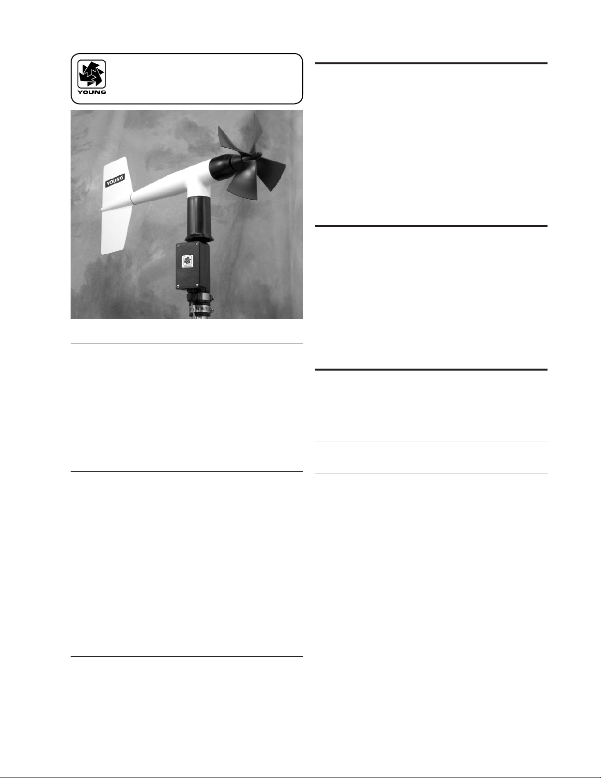
WIND MONITOR
WITH 4-20 mA OUTPUTS
MODEL 05103L
R.M. YOUNG COMPANY 2801 AERO PARK DRIVE, TRAVERSE CITY, MICHIGAN 49686, USA
TEL: (231) 946-3980 FAX: (231) 946-4772 WEB: www.youngusa.com
P/N: 05103L-90
REV: H102811
Page 2
MODEL 05103L
WIND MONITOR
with 4-20mA OUTPUTS
INTRODUCTION
The 05103L Wind Monitor measures wind speed and direction
and provides calibrated win d speed and dir ection signals via
independent loop-powered 4-20 mA analog transmitters. Sensor
housing, nose cone, propeller, and other components use molded
UV-stabilized plastic for strength, corrosion resistance, light weight,
and fast response . Both the propell er and verti cal sh afts u se
stainless steel precision grade ball bearings.
The sensor mounts directly on standard one inch pipe, outside
di ame ter 34 mm (1.34 "). An o rie nta tio n ri ng all ows sen sor
removal without loss of wind direction reference. Both sensor and
orientation ring are secured to the mounting pipe by stainless steel
band clamps. Electrical connections are made in a junction box on
the mounting post.
INITIAL CHECK-OUT
Carefully unpack and check the Wind Monitor for any signs of
shipping damage. Remove the plastic nut on the propeller shaft.
Install th e prope ller on the shaft with t he seri al number of the
propeller facing forward (into the wind) and replace the nut.
Vane and propeller should easily rotate 360° without friction. Check
vane balance by holding the instrument mounting post so the vane
surface is horizontal. It should have near neutral torque. A slight
imbalance will not degrade performance.
WIND SPEED SPECIFICATION SUMMARY
Range 0 to100 m/s (224 mph)
Sensor 18 cm diameter 4-blade helicoid
polypropylene propeller, 29.4 cm air passage
per revolution
Distance Constant 2.7 m (8.9 ft.) for 63% recovery
Threshold Sensitivity 1.0 m/s (2.2 mph)
Transducer Centrally mounted stationary coil, 2K Ohm
nominal DC resistance
Output Signal 4 to 20 mA = 0 to 100 m/s
WIND DIRECTION (AZIMUTH) SPECIFICATION SUMMARY
Range 360° mechanical, 355° electrical (5° open)
Sensor Balanced vane, 38 cm (15 in) turning radius.
Damping Ratio 0.3
Delay Distance 1.3 m (4.3 ft) for 50% recovery
Threshold Sensitivity 1.1 m/s (2.4 mph) at 10° displacement
Damped Natural
Wavelength 7.4 m (24.3 ft)
Undamped Natural
Wavelength 7.2 m (23.6 ft)
Transducer Conductive plastic potentiometer,
10K ohm resistance (±20%),
0.25% linearity, life expectancy 50 million
revolutions
Output Signal 4 to 20 mA = 0 to 360°
GENERAL
Power Requirement: 12 to 30 VDC, 20 mA per channel
Operating Temp: -50 to 50°C (-58 to 122°F)
Che ck operation wit h displays, data loggers, o r other dev ices
before installation.
INSTALLATION
As a general rule, air ow around a structure is disturbed to twice
the height of the structure upwind, six times the height downwind,
and up to twice the height of the structure above ground. To obtain
meaningful data for most applications, locate the instrument well
above or upwind from obstructions. For some applications it may
not be practical or necessary to meet these requirements.
CONNECT THE WIND MONITOR TO EARTH GROUND
AS SHOWN IN THE WIRING DIAGRAM TO AVOID
ERRONEOUS SIGNALS OR SENSOR DAMAGE.
Initial installation is most easily performed using two people; one
to adjust instrument position and the other to observe an indicating
device. After initial installation with the included orientation ring, the
instrument can be removed and returned to its mounting without
re-alignment. Install the Wind Monitor following these steps:
1. MOUNT WIND MONITOR
a) Place orientation ring on mounting post. Do Not tighten band
clamp yet. (Orientation ring may be omitted when portable
tripod is used.)
b) Place Wind Monitor on mounting post. Do Not tighten band
clamp yet.
2. CONNECT SENSOR CABLE.
a) Connect sensor cable according to wiring diagram located at
back of manual.
3. ALIGN VANE
a) Connect instrument to indicator.
b) Choose a known wind direction reference point on the
horizon.
c) Sighting down instrument center line, point nose cone at
reference point on horizon.
d) While holding vane in position, slowly turn base until indicator
shows proper value.
Page 1
05103L-90(H)
Page 3

e) Tighten mounting post band clamp.
f) Engage orientation ring indexing pin in notch at instrument
base.
g) Tighten orientation ring band clamp.
CALIBRATION
The 05103L Wind Monitor is fully calibrated before shipment and
requires no additional adjustment. Check sensor calibration once
per year or as needed. Please see the wiring diagram for output
scaling information.
Calibration checks can be easily performed in the eld using the
calibration accessories available from YOUNG. NIST traceable
win d tunnel calibration is also availab le. Contact YOUNG for
details.
Details on checking bearing torque, which affects wind speed and
direction threshold, appear in the following section.
CALIBRATION FORMULAS
Model 05103L Wind Monitor w / 08234 Propeller
WIND SPEED vs PROPELLER RPM
m/s = 0.00490 x rpm
knots = 0.00952 x rpm
mph = 0.01096 x rpm
km/h = 0.01764 x rpm
WIND SPEED vs mA OUTPUT
m/s = ( 6.250 x mA)-25
knots = (12.141 x mA)-48.6
mph = (13.980 x mA)-56
km/h = (22.500 x mA)-90
WIND DIRECTION vs mA OUTPUT
DEGREES = (22.5 x mA)-90
MAINTENANCE
Given pro per ca re, the Wi nd Mon itor should provi de years of
service. The only components likely to need replacement due to
normal wear are the precision ball bearings and the wind direction
potentiomet er. Only a qualif ie d instrument techni ci an should
perform the replacement. If service facilities are not available,
return the instrument to the company. Refer to the drawings to
become familiar with part names and locations. The asterisk (*)
which appears in the following outlines is a reminder that maximum
torque on all set screws is 80 oz-in.
POTENTIOMETER REPLACEMENT
The potentiometer has a life expectancy of fty million revolutions.
As it becomes worn, the element may begin to prod uce noisy
signals or become non-linear. When signal noise or non-linearity
beco me s unac ce pt able, repl ac e the pot en ti ometer. Ref er to
exploded view drawing and proceed as follows:
1. REMOVE MAIN HOUSING
a) Unscrew nose cone from main housing. Set o-ring aside for
later use.
b) Gently push main housing latch.
c) While pushing latch, lift main housing up and remove it from
vertical shaft bearing rotor.
2. UNSOLDER TRANSDUCER WIRE
a) Remove junction box cover, exposing circuit board.
b) Remove screws holding circuit board.
c) Unsolder three potentiometer wires (white, green, black),
two wind speed coil wires (red, black), and earth ground wire
(red) from board.
05103L-90(H)
3. REMOVE POTENTIOMETER
a) Loosen set screw on potentiometer coupling and remove
it from potentiometer adjust thumbwheel.
b) Loosen set screw on potentiometer adjust thumbwheel
and remove it from potentiometer shaft.
c) Loosen two set screws at base of transducer assembly
and remove assembly from vertical shaft.
d) Unscrew potentiometer housing from potentiometer
mounting & coil assembly.
e) Push potentiometer out of potentiometer mounting & coil
assembly by applying firm but gentle pressure on
potentiometer shaft. Make sure that the shaft o-ring
comes out with the potentiometer. If not, then gently
push it out from the top of the coil assembly.
4. INSTALL NEW POTENTIOMETER
a) Push new potentiometer into potentiometer mounting &
coil assembly making sure o-ring is on shaft.
b) Feed potentiometer and coil wires through hole in bottom
of potentiometer housing.
c) Screw potentiometer housing onto potentiometer
mounting & coil assembly.
d) Gently pull transducer wires through bottom of
potentiometer housing to take up any slack. Apply a
small amount of silicone sealant around hole.
e) Install transducer assembly on vertical shaft allowing
0.5 mm (0.020") clearance from vertical bearing.
Tighten set screws* at bottom of transducer assembly.
f) Place potentiometer adjust thumbwheel on potentiometer
shaft and tighten set screw*.
g) Place potentiometer coupling on potentiometer
adjust thumbwheel. Do Not tighten set screw yet.
5. RECONNECT TRANSDUCER WIRES
a) Using needle-nose pliers or a paper clip bent to form a small
hook, gently pull transducer wires through hole in junction
box.
b) Solder wires to circuit board according to wiring diagram.
Observe color code.
c) Secure circuit board in junction box using two screws
removed in step 2b. Do not overtighten.
6. REPLACE MAIN HOUSING
a) Place main housing over vertical shaft bearing rotor. Be
careful to align indexing key and channel in these two
assemblies.
b) Place main housing over vertical shaft bearing rotor until
potentiometer coupling is near top of main housing.
c) Turn potentiometer adjust thumbwheel until potentiometer
coupling is oriented to engage ridge in top of main housing.
Set screw on potentiometer coupling should be facing the
front opening.
d) With potentiometer coupling properly oriented, continue
pushing main housing onto vertical shaft bearing rotor until
main housing latch locks into position with a “click”.
7. ALIGN VANE
a) Connect excitation voltage and signal conditioning
electronics to terminal strip according to wiring diagram.
b) With mounting post held in position so junction box is facing
due south, orient vane to a known angular reference. Details
appear in CALIBRATION section.
c) Reach in through front of main housing and turn
potentiometer adjust thumbwheel until signal conditioning
system indicates proper value.
d) Tighten set screw* on potentiometer coupling.
8. REPLACE NOSE CONE
a) Screw nose cone into main housing until o-ring seal is
seated. Be certain threads are properly engaged to avoid
cross-threading.
*Max set screw torque 80 oz-in
Page 2
Page 4

FLANGE BEARING REPLACEMENT
If anemometer bearings become noisy or wind speed threshold
increases above an acceptable level, bearings may need
replacement. Check anemometer bearing condition using a Model
18310 Propeller Torque Disc. If necessary, bearings are replaced
as follows.
1. REMOVE OLD BEARINGS
a) Unscrew nose cone. Set o-ring aside for later use.
b) Loosen set screw on magnet shaft collar and remove
magnet.
c) Slide propeller shaft out of nose cone assembly.
d) Remove front bearing cap which covers front bearing.
e) Remove both front and rear bearings from nose cone
assembly. Insert edge of a pocket knife under bearing ange
and lift it out.
WARRANTY
This product is warranted to be free of defects in materials and
construction for a period of 12 months from date of initial purchase.
Liability is limited to repair or replacement of defective item. A copy
of the warranty policy may be obtained from R. M. Young Company.
CE COMPLIANCE
This product has been tested and shown to comply with European
CE requirements for the EMC Directive (see Declaration of
Conformity below). Please note that shielded cable must be used.
Declaration of Conformity
2. INSTALL NEW BEARINGS
a) Insert new front and rear bearings into nose cone.
b) Replace front bearing cap.
c) Carefully slide propeller shaft thru bearings.
d) Place magnet on propeller shaft allowing 0.5 mm (0.020")
clearance from rear bearing.
e) Tighten set screw* on magnet shaft collar.
f) Screw nose cone into main housing until o-ring seal is
seated. Be certain threads are properly engaged to avoid
cross-threading.
VERTICAL SHAFT BEARING REPLACEMENT
Vertical shaft bearings are much larger than the anemometer
bearings. Ordinarily, these bearings will require replacement less
frequently than anemometer bearings. Check bearing condition
using a Model 18331 Vane Torque Gauge.
Since this procedure is similar to POTENTIOMETER
REPLACEMENT, only the major steps are listed here.
1. REMOVE MAIN HOUSING.
2. UNSOLDER TRANSDUCER WIRES AND REMOVE
TRANSDUCER ASSEMBLY. Loosen set screws at base of
transducer assembly and remove entire assembly from vertical
shaft.
3. REMOVE VERTICAL SHAFT BEARING ROTOR by sliding it
upward off vertical shaft.
4. REMOVE OLD VERTICAL BEARINGS AND INSTALL NEW
BEARINGS. When inserting new bearings, be careful not to
apply pressure to bearing shields.
5. REPLACE VERTICAL SHAFT BEARING ROTOR.
6. REPLACE TRANSDUCER & RECONNECT WIRES.
7. REPLACE MAIN HOUSING.
8. ALIGN VANE.
9. REPLACE NOSE CONE.
R. M. Young Company
2801 Aero Park Drive
Traverse City, MI 49686 USA
Model 05103L Wind Monitor
The undersigned hereby declares on behalf of R. M.
Young Company that the above-referenced product, to
which this declaration relates, is in conformity with the
provisions of:
Council Directive 2004/108/EC (December 15, 2004)
on Electromagnetic Compatibility
David Poinsett
R&D Manager
Page 3
05103L-90(H)
Page 5

CABLE & WIRING DIAGRAM
CALIBRATION FORMULAS
Model 05103L
WIND SPEED vs mA OUTPUT
m/s = ( 6.250 x mA)-25
knots = (12.141 x mA)-48.6
mph = (13.980 x mA)-56
km/h = (22.500 x mA)-90
WIND DIRECTION vs mA OUTPUT
DEGREES = (22.5 x mA)-90
05103L-90(H)
Page 4
Page 6

BEARING REPLACEMENT & POTENTIOMETER ADJUSTMENT
Page 5
05103L-90(H)
Page 7

GENERAL ASSEMBLY & REPLACEMENT PARTS
05103L-90(H)
Page 6
Page 8

Calibration Accessories
Model 18802
Anemometer Drive
Vane Angle Bench Stand
Model 18331 Vane Torque Gauge
Model 18112
Model 18310
Propeller Torque Disc
Model 18212
Vane Angle Fixture-Tower Mount
Model 18301
Vane Alignment Rod
Page 9

YOUNG
Calibration Accessories
Model 18802 Anemometer Drive provides a convenient and accurate way to rotate an anemometer shaft at
a known rate. The motor may be set to rotate clockwise or counter-clockwise at any rate between 200 and
15,000 RPM in 100 RPM increments. The LCD display is referenced to an accurate and stable quartz timebase.
For completely portable operation, the unit can be operated on internal batteries. For extended operation, an
AC wall adapter is included.
Model 18811 Anemometer Drive is identical to Model 18802 except the drive motor incorporates a
gear reducer for operation in the range of 20 to 990 RPM in 10 RPM increments. The lower range
is recommended for cup anemometer calibration.
Model 18112 Vane Angle Bench Stand is used for benchtop wind direction calibration of the Wind Monitor
family of sensors. The mounting post engages the direction orientation notch on the Wind Monitor. An easy to
read pointer indicates 0 to 360 degrees with 1/2 degree resolution.
Model 18212 Vane Angle Fixture - Tower Mount similar to the Model 18112, the tower mount feature allows use
on the tower as well as the bench top. The fixture is temporarily placed on the tower between the Wind Monitor
and its tower mounting. Index keys and notches are engaged to preserve direction reference.
Model 18310 Propeller Torque Disc checks anemometer bearing torque with 0.1 gm/cm resolution. The disc temporarily replaces the propeller for torque measurement or simple yet accurate pass/fail
checks. Charts included with the unit relate torque to propeller threshold with limits for acceptable
bearing performance.
Model 18312 Cup-Wheel Torque Disc checks cup anemometer bearing torque.
Model 18331 Vane Torque Gauge checks vane bearing torque of the Wind Monitor family sensors. Slip the
fixture over the main housing and make simple yet accurate vane torque measurements. Charts relating vane
torque to vane threshold provide limits for acceptable bearing performance.
Model 18301 Vane Alignment Rod helps align the vane of a wind sensor to a known direction reference during
installation. The base of the device has an index key that engages the direction orientation notch in the sensor
allowing the sensor to be removed without losing wind direction reference.
Specifications
MODEL 18802 ANEMOMETER DRIVE
(Replaces 18801)
Range:
200 to 15,000 RPM in 100 RPM increments
Rotation:
Clockwise or Counter-Clockwise
Display Resolution:
1 RPM
Quartz Timebase Reference:
0.1 RPM
Power Requirement:
2x 9 V (alkaline or lithium) batteries
115 VAC wall adapter included
(230 VAC – add suffix H)
MODEL 18811 ANEMOMETER DRIVE
(Replaces 18810)
Range:
20 to 990 RPM in 10 RPM increments
Display Resolution:
0.1 RPM
MODEL 18112, 18212 VANE ANGLE
CALIBRATION DEVICES
Range:
0 to 360 degrees
Resolution:
0.5 degree
Ordering Information MODEL
ANEMOMETER DRIVE 200 to 15,000 RPM .............................................. 18802
ANEMOMETER DRIVE 20 TO 990 RPM .................................................. 18811
230V / 50-60 HZ INPUT POWER ...................................................
ADD SUFFIX “H”
VANE ANGLE BENCH STAND .......................................................... 18112
VANE ANGLE FIXTURE - TOWER MOUNT ........................................... 18212
PROPELLER TORQUE DISC............................................................ 18310
CUP-WHEEL TORQUE DISC ........................................................... 18312
VANE TORQUE GAUGE ................................................................. 18331
VANE ALIGNMENT ROD ................................................................ 18301
R.M. YOUNG COMPANY
2801 Aero Park Drive
Traverse City, Michigan 49686 USA
TEL: (231) 946-3980 FAX: (231) 946-4772
E-mail: met.sales@youngusa.com
Web Site: www.youngusa.com
MODEL 18310, 18312 TORQUE DISC DEVICES
Range:
0 to 5.4 gm-cm
Resolution:
0.1 gm-cm
MODEL 18331 VANE TORQUE GAUGE
Range:
0 to 50 gm-cm
Resolution:
5 gm-cm
Specifications subject to change without notice.
Copyright © 2000 R.M. Young Company, Printed in U.S.A. 11/00
 Loading...