


 3OOO
3OOO
MAG CROSSTRAINER
EXERCISES
&
INSTRUCTION
MANUAL
11 / 2002 TWN |
Product may vary slightly from the item pictured. |

YORK 3000 MAG. CROSSTRAINER
SAFETY GUIDELINES:
Please read and follow the following safety guidelines:
Before beginning any exercise program, you should consult with your doctor.
It is recommended that you undergo a complete physical examination.
,
Read this owner s manual and follow the instructions.
Assemble and operate the YORK 3000 MAG. CROSSTRAINER on a solid, level surface.
Keep the area behind the YORK 3000 MAG. CROSSTRAINER clear.
Always use your YORK 3000 MAG. CROSSTRAINER in adequate space e.g., at least 2 ft. (60cm) clearance on each side.
Never allow children on or near the YORK 3000 MAG. CROSSTRAINER.
Always check the YORK 3000 MAG. CROSSTRAINER before using it, in particular make sure all parts are assembled, and nuts and bolts are tightened.
Do not use the YORK 3000 MAG. CROSSTRAINER if the unit is disassembled in any way.
Keep hands away from moving parts.
The weight limit for this product is 225 lbs (100 kgs).
Wear proper workout clothing: Do not wear loose clothing.
Do not wear shoes with leather soles or high heels. Tie all long hair back.
Remove jewellery, rings, chains and pins before exercising.
Do not rock the unit from side to side.
Care should be taken when mounting and dismounting the unit.
Do not place any liquids on any part of the MAG CROSSTRAINER 3000.
,
Do not use any accessories that aren t specifically recommended by the manufacturer, these might cause injuries or cause the unit to fail.
Always consult your doctor before undertaking any exercise programme.
Work within your recommended exercise level, do NOT work to exhaustion.
If you feel any pain or abnormal symptoms, STOP YOUR WORKOUT IMMEDIATELY. Consult your physician immediately.
TAKE CARE TO PROTECT CARPETS AND FLOOR in case of leakages.
This product is a machine and contains moving parts which have been greased / lubricated and could leak.
The YORK 3000 MAG. CROSSTRAINER is designed for the use and enjoyment of the serious trainer as well as the dedicated user. By following the above precautions and using good judgement and common sense, you will have safe and pleasurable exercise regimen with the YORK 3000 MAG. CROSSTRAINER.
CARE AND MAINTENANCE
Use a warm damp cloth with mild detergent
to keep your YORK 3000 MAG. CROSSTRAINER
clean.
TOOLS REQUIRED
The tools enclosed in the carton are two multi-purpose spanners (which one has a screwdriver function) and one allen key.
SHOULD YOU REQUIRE ANY ASSISTANCE REGARDING THIS PRODUCT PLEASE CONTACT YORK DIRECTLY.
HELP LINE
(8:30am- 4:30pm)
YORK BARBELL (U.K.) LTD.
CHURCHILL WAY, DAVENTRY, NORTHANTS, NN11 4YB ENGLAND TEL: (01327) 701-824
FAX: (01327) 706-704
E-MAIL: helpdesk@yorkfitness.co.uk
HELP LINE
(8:30am- 4:30pm)
YORK BARBELL (AUST.) LTD.
UNIT 1, LOT 2, SWAFFHAM ROAD, MINTO, N.S.W. 2566 AUSTRALIA TEL: (02) 9603-8444
FAX: (02) 9603-8555
E-MAIL: paulyork@ozemail.com.au

GENERAL
REMOVE ALL THE PARTS OF YOUR MAG. CROSSTRAINER 3000 FROM THE CARTON AND PLACE THEM ON THE FLOOR CAREFULLY. ASSEMBLING YOUR MAG. CROSSTRAINER 3000 IS SIMPLE.
FOLLOW THESE INSTRUCTIONS CAREFULLY AND IT SHOULD TAKE YOU AROUND 15~20 MINUTES.
ASSEMBLY INSTRUCTION
1.
A
FRONT
STABILIZER
MOVING WHEEL
B
REAR
STABILIZER
END CAP
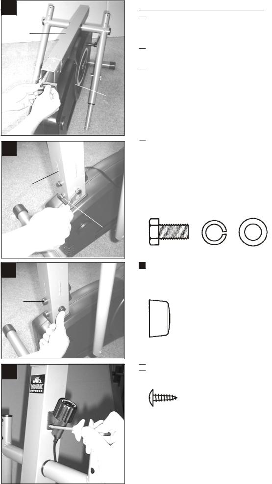
ATTACH THE STABILIZERS
Fix the front stabilizer with moving wheels to the main frame and secure, using two carriage bolts, washers and locknuts.
|
X2 |
8502-58 |
|
8502-40N |
X2 |
8502-14N |
X2 |
 Fix the rear stabilizer to the main frame and secure,using two carriage bolts, washers and locknuts.
X2
8502-58
8502-40N |
X2 |
8502-14N |
X2 |
NOTE: Make sure you fasten the nuts & bolts securely for your safety and comfort when exercising.
* SHOULD YOU REQUIRE ANY ASSISTANCE REGARDING THIS PRODUCT PLEASE CONTACT YORK DIRECTLY. *
2.
A
FRONT
POST
MAIN
FRAME
B
FRONT
POST
MAIN FRAME
BRACKET
C
PLASTIC
CAP
D
ATTACH THE FRONT POST
 Rest the front post on the main frame carefully as shown.
 Connect the sensor wire plug to the middle wire socket.
 Check middle wire runs up the front post and out the top - later this will connect to the computer.
 Insert the front post to the main frame in position and secure, using four hex head bolts, spring washers and washers as shown.
NOTE: TAKE CARE to ensure the middle wire does not get trapped when you attach the front post to the main frame.
X4
8502-20 |
8502-13 |
8502-40N |
Fix the plastic cap onto the bolts head.
X4
8502-54
 Attach the tension control to the front post and secure, using two self tapping screws.
X2
8502-67
* SHOULD YOU REQUIRE ANY ASSISTANCE REGARDING THIS PRODUCT PLEASE CONTACT YORK DIRECTLY. *
3.
A
PEDAL
CURVED EDGE OF
PEDAL FACES
OUTWARDS
RIGHT
PEDAL POST
B
RIGHT
PEDAL
POST
C
 Repeat the same process for
the left pedal post assembly.
ATTACH THE PEDAL POSTS
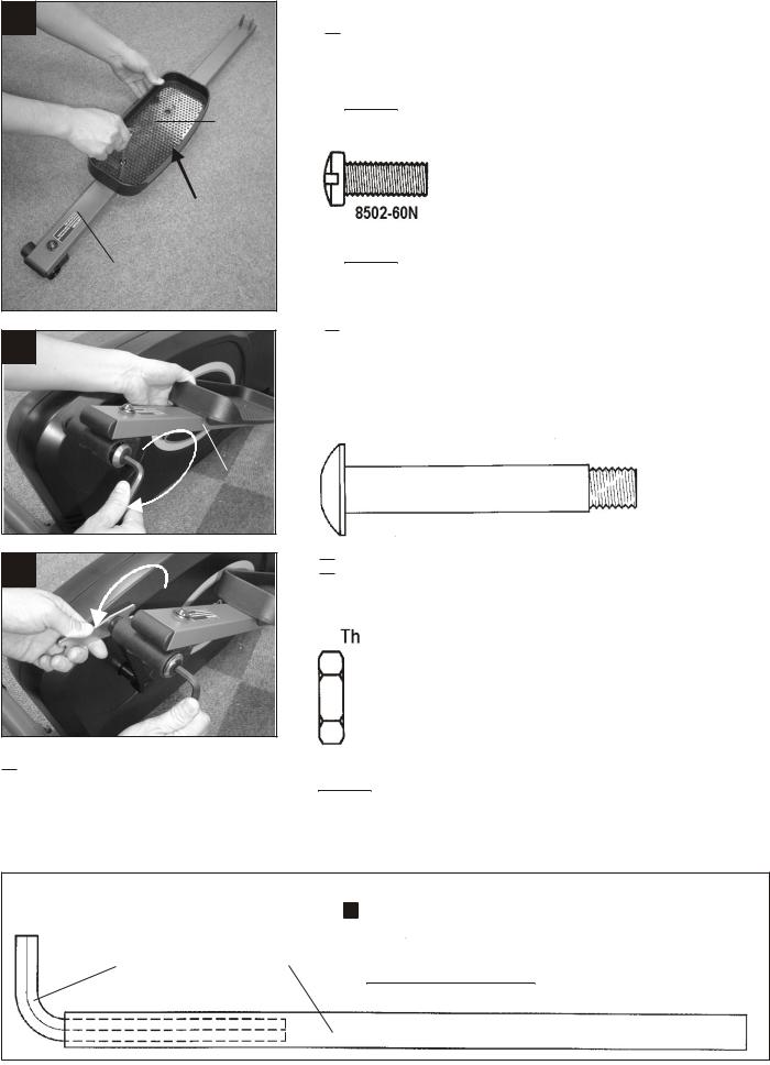
 Attach the pedal to the right pedal post and secure, using two machine screws as shown.
NOTE: The curved edge of the pedal must be fixed faces outwards.
X2
NOTE: Make sure you fasten the screws securely for your safety and comfort when exercising.
 Fix the right pedal post to the right side crank arm and secure, using one allen head bolt as shown.
NOTE: The pedal posts are marked”R” and “L” (Right & Left).
X1
8502-41
 Fully tighten the allen head bolt to the crank then fasten the nut to the allen head bolt protruding through the crank arm tightly.
will secure it in place.
X1
8502-42
NOTE: The right pedal post “R” should be threaded on clockwise. The left pedal post “L” should be threaded on clockwise.
NOTE:
STEEL TUBE
ALLEN KEY
HOLDER
Fit the allen key inside the steel tube holder. This will make it easier to secure the bolts
tightly. It is important these bolts are fully tightened.
CHECK REGULARLY !!
* SHOULD YOU REQUIRE ANY ASSISTANCE REGARDING THIS PRODUCT PLEASE CONTACT YORK DIRECTLY. *
5. A
B
COMPUTER
WIRE
MIDDLE
WIRE
ATTACH THE COMPUTER
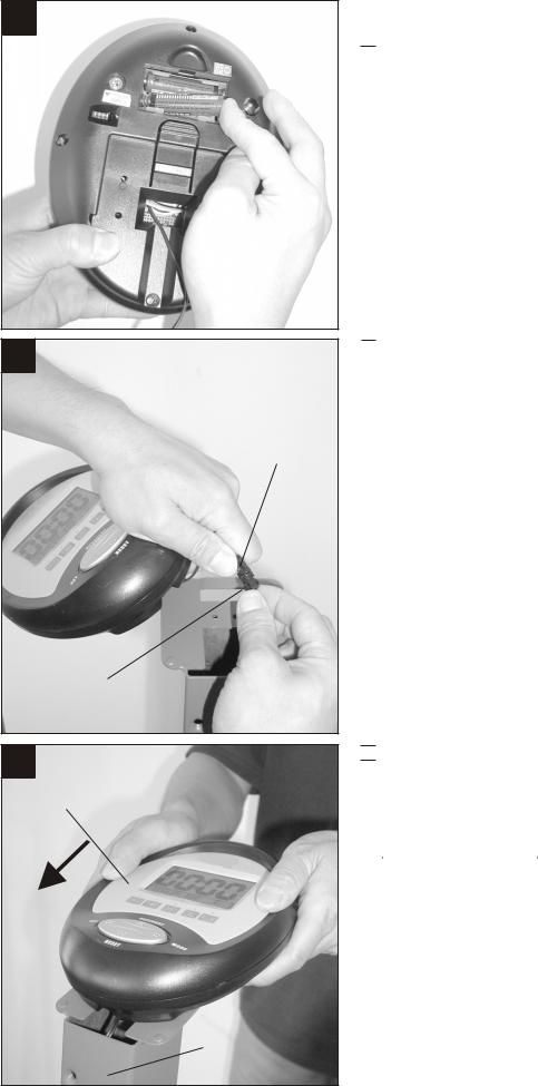
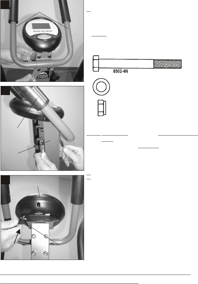
 Insert two batteries (AA size 1.5V) into the compartment in the back of the computer
 Connect the computer wire to the middle wire that runs inside the front post.
C
COMPUTER
FRONT
POST
 Slide the computer wire down the front post then slide the computer onto the bracket on the front post until it click into position.
NOTE: TAKE CARE to ensure the computer wire does not get trapped when you attach the computer to the front post bracket.
* SHOULD YOU REQUIRE ANY ASSISTANCE REGARDING THIS PRODUCT PLEASE CONTACT YORK DIRECTLY. *
4.
A
RIGHT
HANDLE
BAR
POST
RIGHT
PEDAL
POST
B
RIGHT
HANDLE
BAR
RIGHT
HANDLE
BAR
POST
C
RIGHT
HANDLE
BAR
ATTACH THE HANDLE BARS
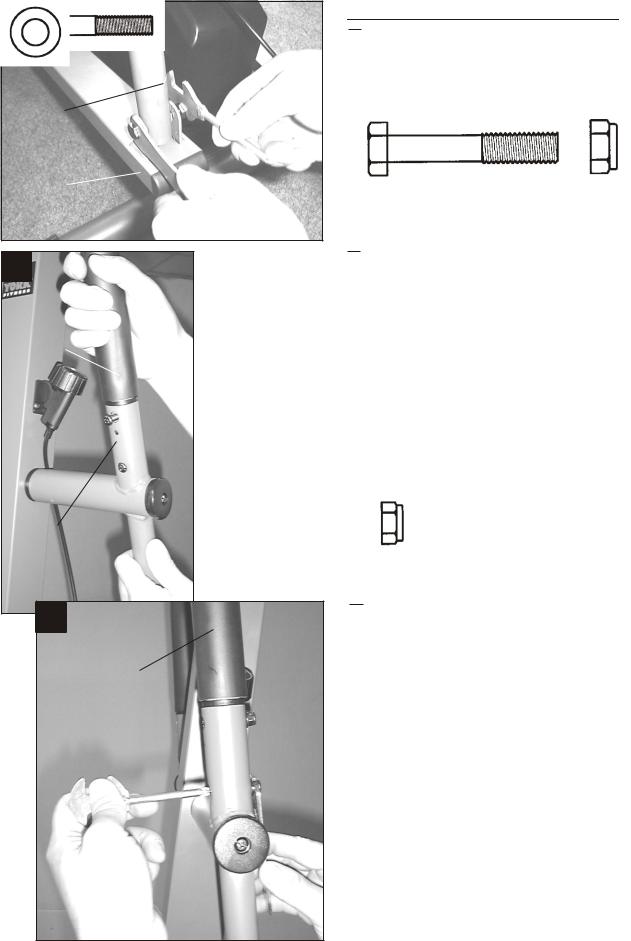
 Fix the right pedal post to the right handle bar post and secure, using hex head bolt and locknut as shown.
X1
8502-63
8502-14N
 Attach the right handle bar to the right handle bar post and secure, using two machine screws, washers and locknuts.
X2
8502-64N
X2
8502-61
X2
8502-05
 Repeat the same process for the left handle bar assembly.
NOTE: The handle bar end caps are marked |
||
,, ,, |
,, |
,, |
R |
and |
L (Right & Left). |
Fix each handle bar to the matching handle bar post.
* SHOULD YOU REQUIRE ANY ASSISTANCE REGARDING THIS PRODUCT PLEASE CONTACT YORK DIRECTLY. *
6.
|
A |
CENTRE |
|
|
BAR |
|
|
FRONT
 POST
POST
B
HAND
PULSE
SENSOR
FRONT
POST
C
COMPUTER
HAND
PULSE
SENSOR
PLUG
ATTACH THE CENTRE BAR
 Attach the centre bar to the front post and secure, using four hex head bolts, washers & nylock nuts as shown.
NOTE: Make sure you fasten the nuts & bolts securely for your safety and comfort when exercising.
X4
X4
8502-40N
X4
8502-14N
NOTE: TAKE CARE to ensure the hand pulse sensor wires does not get trapped when you attach the centre bar to the front post.
 Connect the hand pulse sensor plug to socket on back of computer.
RECHECK THAT ALL THE BOLTS AND NUTS ARE TIGHTENED
SECURELY FOR YOUR SAFETY & COMFORT.
* SHOULD YOU REQUIRE ANY ASSISTANCE REGARDING THIS PRODUCT PLEASE CONTACT YORK DIRECTLY. *
 Loading...