

York EBBA-F024S, E*BA-T036 THRU 090, EABA-F030S, EABA-F036S, EABA-F042S Technical Manual
...Page 1
TECHNICAL
TECHNICAL
GUIDE
GUIDE
SPLIT-SYSTEM
HEAT PUMPS
10 SEER
MODELS:
E*BA-F018 THRU 060
(1.5 THRU 5 NOMINAL TONS, 1 PH)
E*BA-(T,W)036 THRU 090
(3 THRU 7.5 NOMINAL TONS, 3 PH)
MODELS: 018 - 060 (1 PH)
MODELS: 036-048 (3 PH)
MODELS: 060, 090 (3 PH)
O
T
A
D
R
E
I
I
A
F
S
I
T
R
C
E
O
C
M
Y
R
A
T
I
N
U
E
R
T
I
F
I
C
A
R
I
S
with ARI.
P
L
Y
H
E
I
A
T
N
G
P
U
M
P
R
E
T
Q
F
N
U
E
I
P
M
O
S
N
O
I
T
A
C
E
T
S
I
0
N
O
4
2
T
D
A
R
N
A
D
LISTED
R
E
R
U
T
C
A
F
U
N
A
M
C
This product was manufactured
in a plant whose quality system
is certified/registered as being
in conformity with ISO 9001.
Certification applies only
when the complete
system is listed
Due to continuous product improve m ent, specifications
are subject to change without notice.
Visit us on the web at www.york.com for the most
up-to-date technical information.
Additional rating information can be found at
www.ariprimenet.org.
036-21318-002 Rev. A (0106)
DESCRIPTION
The 10 SEER Series heat pumps is the outdoor part of a versatile system of heat pumps. It is designed to be custommatched with one of UPG’s complete line of evaporator sections, with each serving a specific function. Matching Air Handlers are available for upflow, downflow, or horizontal
applications to provide a complete system. Electric Heaters
are available, if required. Add-On coils are availa ble for use
with upflow, downflow, or horizontal furnaces and air handlers.
WARRANTY
Single Phase Units:
5-year limited parts warranty.
5-year limited compressor warranty.
Three Phase Units:
1-year limited parts warranty.
5-year limited compressor warranty.
FEATURES
• QUALITY COILS - The coil is constructed of copper tube and
aluminum fins.
• COIL PROTECTION - Coils are protected from damage by a
polymer mesh applied between the coil face, and a PVC
coated steel coil guard.
• PROTECTED COMPRESSOR - The compressor is internally
protected against high pressure and temperature. This is
accomplished by the simultaneous operation of high pressure
relief valve and a temperature sensor which protects the compressor if undesirable operating conditions occur. A liquid line
filter-drier further protects the compressor.
• DURABLE FINISH - Cabinet is made of pre-painted steel.
The pre-treated flat galvanized steel provides a better paint to
steel bond, which resists corrosion and rust creep. Special
primer formulas and matted-textured finish insure less fading
when exposed to sunlight.
• LOWER INSTALLED COST - Installation time and costs are
reduced by easy power and control wiring connections. Discharge line heat exchanger knockouts are provided, if
required. Available in sweat connect models only. The unit
contains enough refrigerant for matching indoor coils and 15
feet of interconnecting piping. The small base dimension
means less space is required on the ground or roof.
• TOP DISCHARGE - The warm air from the top mounted fan is
blown up away from the structure and any landscaping. This
allows compact location on multi-unit applications.
• LOW OPERATING SOUND LEVEL - The upward air flow carries the normal operating noise away from the living area. The
rigid top panel effectively isolates any motor sound. Isolator
mounted compressor and the rippled fins of the condenser
coil muffle the normal fan motor and compressor operating
sounds.
• LOW MAINTENANCE - Long life permanently lubricated
motor-bearings need no annual servicing.
• EASY SERVICE ACCESS - Fully exposed refrigerant connections, a single panel covering the electrical controls, and
the molex plug in the control box connecting the condenser
fan make for easy servicing of the unit.
• SECURED SERVICE VALVES - Secured re-usable service
valves are provided on both the liquid and vapor sweat connections for ease of evacuating and charging.
• U.L. and C.U.L. listed - approved for outdoor application.
Certified in accordance with the Unitary Small Equipment certification program, which is based on ARI Standard 210/240.
FOR DISTRIBUTION USE ONLY - NOT TO BE USED AT POINT OF RETAIL SALE
Page 2

036-21318-002 Rev. A (0106)
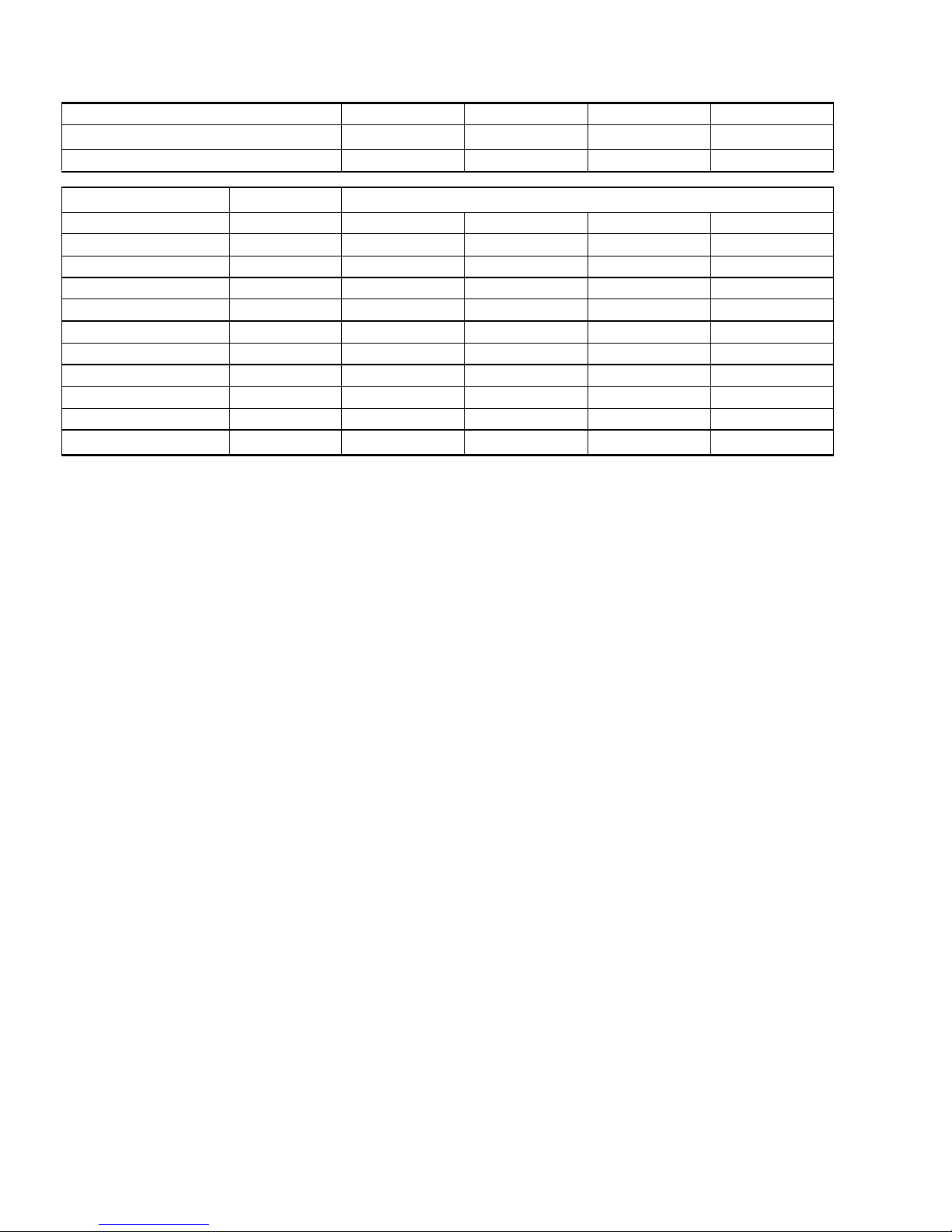
Physical and Electrical Data - 1 Phase
MODEL EBBA-F018S EBBA-F024S EABA-F030S EABA-F036S EABA-F042S EBBA-F048S EABA-F060S
Unit Supply Voltage 208/230 – 1 – 60
Normal Voltage Range
1
Minimum Circuit Ampacity 11.8 14.9 19.0 23 28.5 31.7 40.7
2
Max. Overcurrent Device Amps
Compressor Type
Compressor Amps
3
Rated Load 9.0 11.5 14.1 17.3 21.7 24.3 31.5
Locked Rotor 48 60 73 94 105 140 169
20 25 30 40 40 55 60
Recip Recip Recip Recip Recip
Crankcase Heater Yes Yes Yes Yes Yes No No
Fan Motor Amps Rated Load 0.5 0.5 1.4 1.4 1.3 1.3 1.3
Fan Diameter Inches 18 18 18 18 22 22 22
Rated HP 1/12 1/12 1/4 1/4 1/4 1/4 1/4
Fan Motor
Nominal RPM 1,100 1,100 1,100 1,100 850 850 850
Nominal CFM 1,850 1,850 2,750 2,750 3,150 3,350 3,350
Face Area Sq. Ft. 9.15 12.58 12.58 12.58 15.72 19.65 23.58
Coil
Rows Deep 1111111
Fin / Inches 13 13 14 14 13 13 13
Liquid Line OD 3/8 3/8 3/8 3/8 3/8 3/8 3/8
Vapor Line OD 3/4 3/4 3/4 3/4 3/4 7/8 7/8
Unit Charge (Lbs. - Oz.)
4
4 - 14 5 - 0 4 - 8 5 - 12 6 - 9 8 - 3 9 - 8
Charge Per Foot, Oz. 0.68 0.68 0.68 0.68 0.68 0.70 0.70
Operating Weight Lbs. 131 141 154 159 172 204 217
187 to 252
Scroll
B
Scroll
C
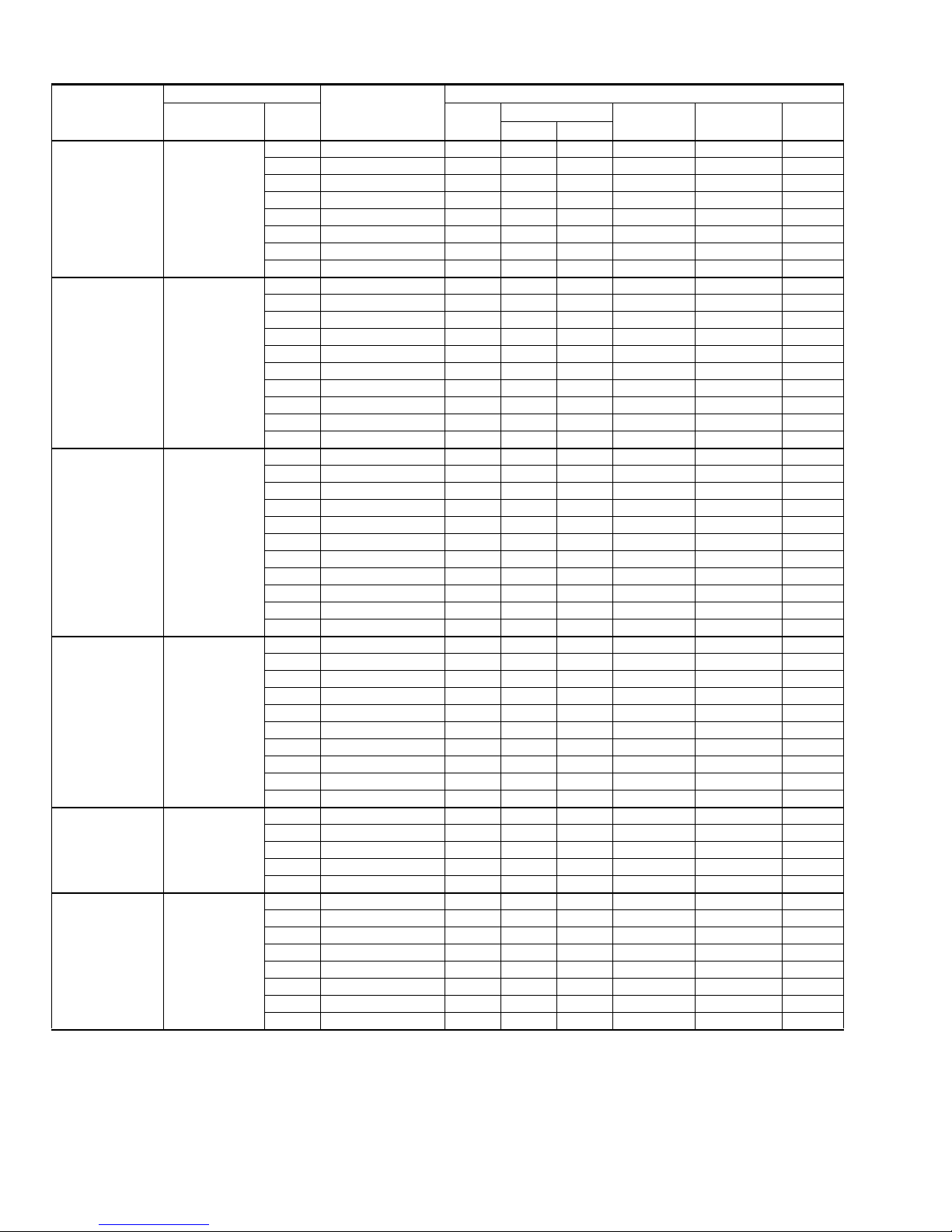
Physical and Electrical Data - 3 Phase
MODEL
EABA-
T036S
Unit Supply Voltage
Normal Voltage Range
Minimum Circuit Ampacity 15.0 18.9 24.5 40.6 8.0 10.1 12.0 20.7
Max. Qvercurrent Device Amps
Compressor Type
Compressor Amps Rated Load 10.9 14.1 18.6 28.8 5.8 7.0 9.0 14.7
Crankcase Heater Yes No No No Yes No No No
Fan Motor Amps Rated Load 1.4 1.3 1.3 4.6 .8 .7 .8 2.3
Fan Diameter Inches 18 22 24 24 18 22 24 24
Fan Motor Rated HP 1/4 1/4 1/4 3/4 1/4 1/5 1/4 3/4
Coil Face Area Sq. Ft. 12.58 19.65 18.00 22.5 12.58 19.65 18.00 22.5
Rows Deep 11221122
Fin / Inches 14 13 14 16 14 13 14 16
Liquid Line OD 3/8 3/8 3/8 1/2 3/8 3/8 3/8 1/2
Vapor Line OD 3/4 7/8 7/8 1-1/8 3/4 7/8 7/8 1-1/8
Unit Charge (Lbs. - Oz.)
Charge Per Foot, Oz. .68 .70 .70 1.26 .68 .70 .70 1.26
Operating Weight Lbs. 178 232 243 354 178 232 243 354
1. Rated in accordance with ARI Standard 110, utilization range “A”.
2. Dual element fuses or HACR circuit breaker.
3. All scrolls listed with a superscript “B” are Bristol scrolls. All scrolls listed with a superscript “C” are Copeland scrolls.
4. The Unit Charge is correct for the outdoor unit, matched indoor coil and 15 feet of refrigerant tubing. For tubing lengths other than
15 feet, add or subtract the amount of refrigerant, using the difference in length multiplied by the per foot value.
1
2
25 30 40 60 15 15 20 35
3
Inertia
Locked Rotor 78 125 128 195 40 55 63 95
Nominal RPM 1,100 850 850 1100 1,100 825 850 1100
Nominal CFM 2,750 3,500 3,100 5000 2,750 3,500 3,100 5000
4
5 - 12 8 - 3 11 - 3 16 5 - 12 8 - 3 11 - 3 16
EBBA-
T048S
EABA-
T060S
EABA-
T090S
EABAW036S
EBBAW048S
208/230-3-60 460 - 3 - 60
187 to 252 432 to 504
Scroll
B
Scroll
C
Scroll
C
Inertia
Scroll
B
EABA-
W060S
Scroll
EABAW090S
C
Scroll
C
2 Unitary Products Group
Page 3

036-21318-002 Rev. A (0106)
Additional R-22 Charge / Orifice Size for Various Matched Systems - 1 Phase
Outdoor Unit EBBA-F018S EBBA-F024S EABA-F030S EABA-F036S EABA-F042S EBBA-F048S EABA-F060S
Unit Orifice (s)
Factory R-22 Charge, lbs-oz 4 - 14 5 - 0 4 - 8 5 - 12 6 - 9 8 - 3 9 - 8
Indoor Coil
G2FD024S(H)17 61 53 + 12 59 + 9 — — — — —
G2FD030S(H)17 65 — 61 + 9 67 + 17 — — — —
G2FD035S(H)14 65 — 61 + 9 67 + 17 — — — —
G2FD036S(H)17/21 75 — — — 69 + 2 — — —
G2FD042S(H)21 78 — — — 71 + 7 — — —
G2FD046S(H)17 78 — — — 71 + 7 81 + 8 — —
G2FD048S(H)21/24 84 — — — — 81 + 15 87 + 6 —
G2FD060S(H)24 90 — — — — — 84 + 4
G1HD024 59 53 + 13 59 + 9 — — — — —
G1HD036 69 — — 67 + 22 69 + 4 — — —
G1HD048 81 — — — — 81 + 10 84 + 6 -
G1HD060 93 — — — — — 84 + 0
G1FA/G1UA024S14/17 59 53 + 10 — — — — — —
G1FA/G1UA030S14 65 — 59 + 10 — — — — —
G1FA/G1UA036S14 73 — - 67 + 17 — — — —
G1FA/G1UA03617/21 73 — 61 + 9 67 + 15 — — — —
G1FA/G1UA048S21/24 84 — — — 71 + 12 81 + 13 84 + 3 —
G1FA/G1UA060S24 90 — — — — — 84 + 4
G1NA030S17H 57 53 + 0 59 + 0 69 + 0 — — — —
G1NA030S21B 57 53 + 0 59 + 0 69 + 0 — — — —
G1NA036S17L 71 — — — 67 + 7 — — —
G1NA048S21D 78 — — — 67 + 7 75 + 0 81 + 8 —
G1NA048S24P 78 — — — — 75 + 0 81 + 8 —
G1NA060S24T 87 — — — — — — 87 + 0
G1NF024SOF 63 —
G1NF036SOF 67 — —
G1NF048SOF 78 — — — —
G1NF060SOF 87 — — — — — —
F2RP/F2FP018 53 51 + 10 — — — — — —
F2RP/F2FP024 61 51 + 21 59 + 9 — — — — —
F2RP/F2FP030 65 — — 69 + 19 — — — —
F2RP/F2FP036 75 — — 69 + 23 71 + 4 — — —
F2RP/F2FP042 78 — — — 71 + 7 81 + 8 — —
F2FP048 84 — — — — 81 + 15 84 + 0 —
F2FP060 90 — — — — — 87 + 4
FOOTNOTES:
1. These orifices are packed in the customer packet of each outdoor unit.
2. These orifices are factory mounted in the flow control device of each indoor coil.
3. TXV kit must be used with these coils to obtain system performance. (701,702,703 indicates 1TV07 ...series).
4. Systems matched with furnaces or air handlers not equipped with blower-off delays, may require blower Time Delay Kit #2FD0670224.
1
Coil Orifice
51,53 59,61 67, 69 67, 69, 71 75,78,81 81,84,87 87
2
59 + 0
System Orifice - Additional Charge, Oz
4
—————
4
69 + 0
67 + 7
4
———
4
75 + 0
84 + 4
3
+ 1
703
3
+ 1
703
3
+ 1
703
4
—
87 + 0
703
3
4
+ 1
PROCEDURES:
1. Unit factory charge listed on the unit nameplate includes refrigerant for the condenser, the smallest evaportor and for 15 feet of interconnecting line tubing.
2. Verify the orifice size and additional charge required for specific evaportor coil in the system using the above table.
3. Additional charge for the amount of interconnecting line tubing greater than 15 feet at the rate specified in the table above.
4. Permanently mark the unit nameplate with the total system charge. Total System Charge = Base Charge (as shipped) + adder for
evaportor + adder for line set.
5. If the orifice in the evaportor was changed, verify the evaportor nameplate has been marked with the correct orifice size.
Unitary Products Group 3
Page 4
036-21318-002 Rev. A (0106)
Additional R-22 Charge / Orifice Size for Various Matched Systems - 3 Phase
Outdoor Unit EABA-(T,W)036S EBBA-(T,W)048S EABA-(T,W)060S EABA-(T,W)090S
Unit Orifice (s)
1
Factory R-22 Charge, lbs-oz 5 - 12 8 - 3 11 - 3 16.0
71, 75 81, 84, 87 99 —
Indoor Coil
Coil Orifice
2
System Orifice = Additional Charge, Oz
G1NA036S17L 67 71 + 7 — — —
G1NA048S21D 67 71 + 7 81 + 8 — —
G1NA048S24P 78 — 81 + 8 — —
G1UA048S21 84 81 + 13 84 + 3 — —
G1UA060S24 90 — 84 + 4 99 + 0 —
G1FA048S21 84 81 + 13 84 + 3 —
G1FA060S24 90 — 84 + 4 99 + 0 —
G2FD042(S,H)21 78 81 + 8 — — —
G2FD048(S,H)21/24 84 — 87 + 6 — —
G2FD060(S,H)24 90 — 84 + 4 99 + 0 —
F3EH090A33
TXV———
TXV
FOOTNOTES:
1. These orifices are packed in the instruction/warranty packet of each outdoor unit.
2. These orifices are factory mounted in the flow control device of each indoor coil.
3. A TXV is factory mounted in the coil or air handler.
PROCEDURES:
1. Unit factory charge listed on the unit nameplate includes refrigerant for the condenser, the smallest evaportor and for 15 feet of interconnecting line tubing.
2. Verify the orifice size and additional charge required for specific evaportor coil in the system using the above table.
3. Additional charge for the amount of interconnecting line tubing greater than 15 feet at the rate specified in the table above.
4. Permanently mark the unit nameplate with the total system charge. Total System Charge = Base Charge (as shipped) + adder for
evaportor + adder for line set.
5. If the orifice in the evaportor was changed, verify the evaportor nameplate has been marked with the correct orifice size.
3
+ 0
4 Unitary Products Group
Page 5

036-21318-002 Rev. A (0106)
COOLING CAPACITY - With Air Handler Coils
COOLING
SEER
W/O TXV
SEER
WITH TXV
EER
3
UNIT MODEL
MODEL
AIR HANDLER
ELECTRIC
HEAT KW
2
W
COIL
MODEL
1
RATED
CFM
NET MBH
TOTAL SENS.
1 PH 10 SEER HP WITH N-AH / G2FD
EBBA-F018S N1AHB0806 2,5,8,10 17 G2FD024(S,H)17 650 17.8 12.8 10.10 - 8.95
EBBA-F024S N1AHB0806 2,5,8,10 17 G2FD030(S,H)17 840 22.6 16.2 10.00 - 9.30
EABA-F030S N1AHB1206 5,8,10,15,19 17 G2FD030(S,H)17 1000 28.0 19.6 10.00 - 9.10
EABA-F036S N1AHB1206 5,8,10,15,19 17 G2FD036(S,H)17 1250 33.6 24.9 10.00 - 8.80
EABA-F042S N1AHC1606 5,8,10,15,20 21 G2FD048(S,H)21 1400 40.0 29.6 10.10 - 9.15
N1AHC1606 5,8,10,15,20 21 G2FD048(S,H)21 1600 45.5 33.7 10.00 - 9.45
EBBA-F048S
N1AHD2006 8,10,15,20,25,30 24 G2FD048(S,H)24 1600 45.5 33.7 10.00 - 9.45
N1AHD2006 8,10,15,20,25,30 24 G2FD060(S,H)24 1600 46.5 34.4 10.20 - 9.60
EABA-F060S N1AHD2006 8,10,15,20,25,30 24 G2FD060(S,H)24 1800 54.5 39.2 - 10.00 8.95
3 PH 10 SEER HP WITH N-AH / G2FD
EABA-(T,W)036S N1AHC1646 10,15 21 G2FD042(S,H)21 1250 34.2 25.3 10.00 - 8.95
EBBA-(T,W)048S)
N1AHC1646 10,15 21 G2FD048(S,H)21 1600 45.5 33.7 10.00 - 9.45
N1AHD2046 10,15,29 24 G2FD048(S,H)24 1600 45.5 33.7 10.00 - 9.45
EABA-(T,W)060S N1AHD2046 10,15,29 24 G2FD060(S,H)24 1700 57.0 41.0 10.00 - 9.80
1 PH 10 SEER HP / F2RP / RC / FP / FC
EBBA-F018S
EBBA-F024S
EABA-F030S
EABA-F036S
EABA-F042S
EBBA-F048S
F2RP/FP018 2,5,8 18 - 600 17.0 12.3 10.00 - 8.90
F2RP/FP024 5,8,10 18 - 650 17.8 12.4 10.00 - 8.95
F2RP/FP024 5,8,10 18 - 800 22.0 16.5 10.00 - 9.30
F2RP/FP030 5,8,10,15 18 - 840 22.6 16.8 10.00 - 9.40
F2RP/FP030 5,8,10,15 18 - 1000 28.4 21.0 10.00 - 9.20
F2RP/FP036 5,8,10,15,19 21 - 1000 29.0 20.9 10.00 - 9.40
F2RP/FP036 5,8,10,15,19 21 - 1250 34.0 24.9 10.00 - 9.00
F2RP/FP042 5,8,10,15 21 - 1250 34.0 24.9 10.00 - 9.00
F2RP/FP042 5,8,10,15 21 - 1400 39.0 28.4 10.00 - 8.90
F2FP048 5,8,10,15,20,25 24 - 1400 39.5 28.8 10.00 - 9.15
F2FP048 5,8,10,15,20,25 24 - 1600 45.0 33.5 10.00 - 9.40
F2FP060 5,8,10,15,20,25 24 - 1600 46.5 34.4 10.00 - 9.60
EABA-F060S F2FP060 5,8,10,15,20,25 24 - 1850 54.0 40.5 - 10.00 8.60
4,5
EABA-(T,W)036S)
EBBA-(T,W)048S
3 PH 10 SEER HP / F2RP / RC / FP / FC
F2RP/FP036 5,8,10,15,19 21 - 1250 34.0 24.9 10.00 - 9.00
F2RP/FP042 5,8,10,15 21 - 1250 34.0 25.6 10.00 - 9.00
F2FP048 5,8,10,15,20,25 24 - 1600 45.0 33.5 10.00 - 9.40
F2FP060 5,8,10,15,20,25 24 - 1600 46.5 34.4 10.00 - 9.60
EABA-(T,W)060S) F2FP060 5,8,10,15,20,25 24 - 1700 56.0 40.0 10.00 - 9.40
3 PH 10 SEER HP / FHP
EABA-(T,W)090S FCEH090 10,16,26,36 25-1/8 - 3000 91.0 87.4 - - 9.50
Rated in accordance with DOE test procedures (Federal Register 12-27-79 and 3-18-88) and ARI Standards 210/240.
Cooling MBH based on 80°F entering air temperature, 50% RH, and rated air flow.
KW includes compressor, outdoor fan and indoor blower motor watts. Add-on coils include 365 watts/1000 CFM for blower motor.
EER (Energy Efficiency Ratio) is the total cooling output in BTU’s at a 95°F outdoor ambient divided by the total electric power in watt-hours at those conditions.
SEER (Seasonal Energy Efficiency Ratio) is the total cooling output in BTU’s during a normal annual usage period for cooling divided by the total electric power input
in watt-hours during the same period.
1. G2FD coils available with a factory installed horizontal drain pan. See price pages for specific model number.
2. Single phase units require single phase 2HK heaters.
3. TXV = Use 1TV700 Series Kit.
4. To meet R=4.2 insulation requirements, substit ute F2FP for F2RP, and F2FC for F2RC. models. All ratings remain the same.
5. FG8, FG9, and FL8 furnaces and F2RP / F2RC air handlers have B.O.D. standard.
- = Not applicable
Unitary Products Group 5
Page 6
036-21318-002 Rev. A (0106)
COOLING CAPACITY - Up flow, Downflow, & Horizontal Furnaces and Coils
UNIT MODEL
EBBA-F018S
EBBA-F024S
EABA-F030S
EABA-F036S
EABA-(T,W)036S)
EABA-F042S
For Notes see Page 5.
FURNACE**
CFM RANGE
(MIN.-MAX.)
575
725
750
950
875
1125
1100
1400
1100
1400
1225
1575
W
14,17 G1FA024S14,17 650 17.6 12.7 10.00 - 8.85
14 G1FA030S14 650 17.8 12.9 10.10 - 8.95
- G1HD024 650 18.0 12.9 10.10 - 9.00
17 G1NA030S17H 650 18.0 13.5 10.00 - 9.20
21 G1NA030S21B 650 18.0 13.5 10.00 - 9.20
14,17 G1UA024S14,17 650 17.6 12.7 10.00 - 8.85
14 G1UA030S14 650 17.8 12.9 10.10 - 8.95
14,17 G2FD024(S,H)14,17 650 17.8 12.8 10.10 - 8.95
14 G1FA030S14 830 22.2 16.4 10.00 - 9.25
17,21 G1FA036S17,21 840 22.6 16.2 10.00 - 9.30
- G1HD024 800 22.2 16.4 10.00 - 9.35
17 G1NA030S17H 850 23.0 16.1 10.00 - 9.50
21 G1NA030S21B 850 23.0 16.1 10.00 - 9.50
14 G1UA030S14 830 22.2 16.4 10.00 - 9.25
17,21 G1UA036S17,21 840 22.6 16.2 10.00 - 9.30
14,17 G2FD024(S,H)14,17 800 22.0 15.8 10.00 - 9.30
17 G2FD030(S,H)17 840 22.6 16.2 10.00 - 9.30
14 G2FD035(S,H)14 840 22.6 16.2 10.00 - 9.30
14 G1FA036S14 1000 28.4 20.6 10.00 - 9.10
17,21 G1FA036S17,21 1000 28.0 20.2 10.00 - 9.10
- G1HD036 1000 28.4 21.0 10.10 - 9.20
17 G1NA030S17H 1050 29.0 20.6 10.00 - 9.40
21 G1NA030S21B 1050 29.0 20.6 10.00 - 9.40
14 G1UA036S14 1000 28.4 20.6 10.00 - 9.10
17,21 G1UA036S17,21 1000 28.0 19.6 10.00 - 9.10
17 G2FD030(S,H)17 1000 28.0 19.6 10.00 - 9.10
14 G2FD035(S,H)14 1000 28.0 19.6 10.00 - 9.10
17 G2FD036(S,H)17 1025 28.4 19.9 10.10 - 9.20
21 G2FD036(S,H)21 1000 28.6 19.9 10.15 - 9.25
21,24 G1FA048S21 1250 34.4 24.7 10.00 - 9.05
- G1HD036 1200 33.4 24.7 10.00 - 8.85
- G1HD048 1200 35.2 26.0 10.00 - 9.10
17 G1NA036S17L 1250 35.0 26.2 10.00 - 9.00
21 G1NA048S21D 1250 35.0 26.2 10.00 - 8.95
21,24 G1UA048S21 1250 34.4 24.7 10.00 - 9.05
17 G2FD036(S,H)17 1250 33.6 24.9 10.00 - 8.80
21 G2FD036(S,H)21 1200 34.0 24.5 10.00 - 9.05
21 G2FD042(S,H)21 1250 34.2 25.3 10.00 - 8.95
17 G2FD046(S,H)17 1250 34.6 25.6 10.00 - 9.05
21,24 G1FA048S21 1250 34.4 24.7 10.00 - 9.05
17 G1NA036S17L 1250 35.0 26.2 10.00 - 9.00
21 G1NA048S21D 1250 35.0 26.2 10.00 - 8.95
21,24 G1UA048S21 1250 34.4 24.7 10.00 - 9.05
21 G2FD042S21 1250 34.2 25.3 10.00 - 8.95
21,24 G1FA048S21 1400 39.5 28.4 10.00 - 9.20
- G1HD048 1400 39.5 32.9 10.00 - 9.10
21 G1NA048S21D 1400 40.5 28.6 10.00 - 9.50
21,24 G1UA048S21 1400 39.5 28.4 10.00 - 9.20
21 G2FD042(S,H)21 1400 39.0 28.9 10.00 - 9.05
17 G2FD046(S,H)17 1400 39.5 29.3 10.00 - 9.10
21,24 G2FD048(S,H)21,24 1400 40.0 29.6 10.10 - 9.15
24 G2FD060(S,H)24 1450 40.0 29.6 10.20 - 9.30
COIL
MODEL
RATED
CFM
NET MBH
TOTAL SENS.
COOLING
SEER
W/O TXV
SEER + TXV
+ TDR*
1
EER
6 Unitary Products Group
Page 7
COOLING CAPACITY - Upflow, Downflow, & Horizontal Furnaces and Coils (Continued)
036-21318-002 Rev. A (0106)
UNIT MODEL
FURNACE**
CFM RANGE
(MIN.-MAX.)
W
COIL
MODEL
RATED
CFM
21,24 G1FA048S21 1600 44.5 33.1 10.00 - 9.30
21,24 G1FA060S21,24 1600 46.5 34.4 10.20 - 9.60
- G1HD048 1600 44.5 33.1 10.00 - 9.30
- G1HD060 1600 46.0 34.1 10.10 - 9.55
21 G1NA048S21D 1600 43.5 32.2 10.00 - 9.25
21,24 G1UA048S21 1600 44.5 33.1 10.00 - 9.30
EBBA-F048S
1400
1800
21,24 G1UA060S21,24 1600 46.5 34.4 10.20 - 9.60
21,24 G2FD048(S,H)21,24 1600 45.5 33.7 10.00 - 9.45
24 G2FD060(S,H)24 1600 46.0 34.0 10.20 - 9.60
21,24 G1FA048S21 1600 45.5 32.7 10.00 - 9.30
EBBA-(T,W)048S)
1400
1800
21 G1NA048S21D 1600 45.0 31.2 10.00 - 9.50
21,24 G1UA048S21 1600 45.5 32.7 10.00 - 9.30
21,24 G2FD048(S,H)21,24 1600 45.5 33.7 10.00 - 9.40
21,24 G1FA060S21,24 1800 54.5 39.2 - 10.00 8.90
- G1HD060 2000 54.5 33.9 - 10.00 8.80
24 G1NA060S24T 1850 53.5 35.5 10.00 - 9.00
21,24 G1UA060S21,24 1800 54.5 39.2 - 10.00 8.90
EABA-F060S
1600
2100
24 G2FD060(S,H)24 1800 54.5 39.2 - 10.00 8.90
21,24 G1FA060S21,24 1700 57.0 41.0 10.00 - 9.80
21,24 G1UA060S21,24 1700 57.0 41.0 10.00 - 9.80
24 G2FD060(S,H)24 1700 57.0 41.0 10.00 - 9.80
EABA-(T,W)060S
1600
2100
1. TXV = Use 1TV700 Series Kit.
* Requires a 2FD Blower Time Delay unless a standard furnace is equipped with one.
Refer to Quick Selection Chart for specific furnace match-up.
**
NET MBH
TOTAL SENS.
COOLING
SEER
W/O TXV
SEER + TXV
+ TDR*
1
EER
HEATING PERFORMANCE - With Air Handler
UNIT
MODEL*
COIL
MODEL
1
ARI HEATING
47°F17°F HSPF -3°F7°F17°F27°F37°F47°F57°F
2
OUTDOOR TEMP
MBH COP MBH COP STD MBH KW MBH KW MBH KW MBH KW MBH KW MBH KW MBH KW
EBBA-F018S
EBBA-F024S
EABA-F030S
EABA-F036S
F2RP/F2FP018 17.0 2.96 9.1 1.78 6.80 6.2 1.43 7.4 1.46 9.1 1.50 11.2 1.61 14.0 1.62 17.0 1.68 18.2 1.75
F2RP/F2FP024 17.0 3.00 10.6 2.06 7.00 7.2 1.44 8.6 1.47 10.6 1.52 13.0 1.63 14.0 1.59 17.0 1.66 18.2 1.73
F2RP/F2FP024 22.0 3.20 11.5 1.88 7.00 7.5 1.56 9.3 1.66 11.5 1.78 13.0 1.87 19.4 1.91 22.0 2.00 24.8 2.08
F2RP/F2FP030 24.0 3.16 14.0 2.06 7.30 7.7 1.52 9.6 1.62 14.0 1.74 13.4 1.83 19.8 1.90 24.0 2.00 25.4 2.07
F2RP/F2FP030 28.8 3.10 16.2 2.00 7.20 10.5 1.99 13.5 2.19 16.2 2.26 19.6 2.46 25.3 2.59 28.8 2.72 33.0 2.86
F2RP/F2FP036 29.0 3.10 18.0 2.22 7.40 11.6 2.11 15.0 2.32 18.0 2.39 19.8 2.47 25.5 2.61 29.0 2.74 33.2 2.88
F2RP/F2FP036 34.0 3.00 20.4 2.16 7.20 15.5 2.40 15.6 2.54 20.4 2.80 24.9 3.03 29.9 3.20 34.0 3.32 38.5 3.50
F2RP/F2FP042 34.0 3.00 20.4 2.14 7.20 11.3 2.41 15.9 2.67 20.4 2.79 25.7 3.11 31.0 3.44 34.0 3.32 38.5 3.50
EABA(T,W)036S F2RP/F2FP036 34.0 3.00 20.4 2.16 7.20 15.5 2.40 15.6 2.54 20.4 2.80 24.9 3.03 29.9 3.20 34.0 3.32 38.5 3.50
EABA-F042S
EBBA-F048S
F2RP/F2FP042 39.0 3.18 23.4 2.06 7.40 13.0 3.15 18.2 3.24 23.4 3.33 27.0 3.28 30.6 3.23 39.0 3.59 44.2 3.68
F2FP048 39.5 3.30 23.4 2.12 7.40 12.4 2.97 17.9 3.10 23.4 3.23 28.9 3.37 32.5 3.39 39.5 3.51 47.5 3.64
F2FP048 45.5 3.18 30.4 2.38 7.5 20.1 3.42 25.3 3.57 30.4 3.73 35.5 3.85 38.8 3.98 45.5 4.16 53.1 4.40
F2FP060 46.0 3.24 30.4 2.38 7.5 21.3 3.44 25.3 3.63 30.4 3.75 35.9 3.84 39.2 3.97 46.0 4.16 53.6 4.40
EBBA-(T,W)048S) F2FP048 47.0 3.08 31.4 2.32 7.50 20.8 3.64 26.1 3.80 31.4 3.97 36.7 4.13 40.1 4.27 47.0 4.47 54.6 4.71
EABA-F060S F2FP060 57.0 3.04 37.4 2.22 7.50 24.3 4.59 30.9 4.76 37.4 4.94 44.0 5.11 48.6 5.25 57.0 5.50 67.0 5.79
EABA-(T,W)060S F2FP060 58.5 3.12 39.0 2.34 7.60 26.0 4.48 32.5 4.68 39.0 4.88 42.1 4.98 45.1 5.07 58.5 5.49 65.0 5.70
EABA(T,W)090S F2EH090 83.0 3.00 54.0 2.15 -- 34.7 7.15 44.3 7.34 54.0 7.53 55.0 7.57 55.9 7.60 83.0 8.11 92.7 8.30
1. Rated CFM same as for cooling.
2. Heating MBH based on ARI standards of 70° DB entering indoor air , 72 % RH o ut do or ai r wit h 25 fe et of interconn ectin g pipi ng a nd n o supp lemental
electric heat operation.
3. Integrated heating capacities include the effect of defrost cycles in the temperature range where they occur.
COP equals MBH output divided by (total KW input x 3.412).
HSPF (Heating Seasonal Performance Factor) is the total heating output during a normal annual usage period for heating divided by the total electric
power input during the same period.
— = Not Applicable.
3
Unitary Products Group 7
Page 8

036-21318-002 Rev. A (0106)
HEATING PERFORMANCE - With Furnace Coils
UNIT
MODEL*
EBBA-F018S
EBBA-F024S
EABA-F030S
EABA-F036S
EABA-(T,W)036S
EABA-F042S
EBBA-F048S
For Notes see Page 7.
1
COIL
MODEL
G2FD024(S,H)14,17 17.0 3.02 10.6 2.06 7.0 6.4 1.41 8.5 1.46 10.6 1.51 12.7 1.56 14.8 1.60 17.0 1.65 20.3 1.69
G1HD024 17.23.0410.62.06 7.0 6.2 1.41 8.4 1.4610.61.5112.41.5914.31.6717.21.6619.41.71
G1NA030S17H 17.2 2.96 10.6 2.06 7.1 6.2 1.38 8.4 1.44 10.6 1.51 12.4 1.55 14.3 1.59 17.2 1.70 19.4 1.77
G1NA030S21B 17.2 2.96 10.6 2.06 7.1 6.2 1.38 8.4 1.44 10.6 1.51 12.4 1.55 14.3 1.59 17.2 1.70 19.4 1.77
G1UA024S14,17 16.8 2.95 10.6 2.02 6.9 6.4 1.44 8.5 1.49 10.6 1.54 12.7 1.59 14.8 1.64 16.8 1.67 20.3 1.80
G1FA024S14,17 16.8 2.95 10.6 2.02 6.9 6.4 1.44 8.5 1.49 10.6 1.54 12.7 1.59 14.8 1.64 16.8 1.67 20.3 1.80
G2FD035(S,H)14 22.6 3.28 11.9 2.00 7.3 4.7 1.55 8.3 1.65 11.9 1.74 15.5 1.84 19.1 1.93 22.6 2.02 27.3 2.18
G2FD030(S,H)17 22.6 3.28 11.9 2.00 7.3 4.7 1.55 8.3 1.65 11.9 1.74 15.5 1.84 19.1 1.93 22.6 2.02 27.3 2.18
G2FD024(S,H)14,17 22.4 3.20 11.6 2.00 7.1 4.4 1.46 8.0 1.58 11.6 1.70 15.2 1.82 18.8 1.94 22.4 2.05 27.1 2.23
G1HD024 22.4 3.24 11.8 2.00 7.1 4.7 1.53 8.2 1.63 11.8 1.73 15.4 1.83 18.9 1.93 22.3 2.02 27.3 2.18
G1NA030S17H 23.4 3.28 13.3 2.10 7.4 6.1 1.63 9.5 1.72 13.0 1.81 16.0 1.92 19.0 2.03 23.4 2.09 26.9 2.18
G1NA030S21B 23.4 3.28 13.3 2.10 7.4 6.1 1.63 9.5 1.72 13.0 1.81 16.0 1.92 19.0 2.03 23.4 2.09 26.9 2.18
G1UA030S14 22.4 3.20 11.6 2.00 7.1 4.4 1.46 8.0 1.58 11.6 1.70 15.2 1.82 18.8 1.94 22.4 2.05 27.1 2.23
G1UA036S17,21 22.6 3.28 11.9 2.00 7.3 4.7 1.55 8.3 1.65 11.9 1.74 15.5 1.84 19.1 1.93 22.6 2.02 27.3 2.18
G1FA030S14 22.4 3.20 11.6 2.00 7.1 4.4 1.46 8.0 1.58 11.6 1.70 15.2 1.82 18.8 1.94 22.4 2.05 27.1 2.23
G1FA036S17,21 22.6 3.28 11.9 2.00 7.3 4.7 1.55 8.3 1.65 11.9 1.74 15.5 1.84 19.1 1.93 22.6 2.02 27.3 2.18
G2FD030(S,H)14,17 29.0 3.08 18.0 2.20 7.4 9.4 2.08 13.7 2.24 18.0 2.40 22.3 2.56 26.9 2.71 29.0 2.76 34.6 2.98
G2FD035(S,H)14 29.0 3.08 18.0 2.20 7.4 9.4 2.08 13.7 2.24 18.0 2.40 22.3 2.56 26.9 2.71 29.0 2.76 34.6 2.98
G2FD036(S,H)14 29.2 3.10 18.2 2.20 7.4 10.9 2.20 14.5 2.31 18.2 2.42 21.3 2.56 24.3 2.69 29.2 2.76 32.9 2.87
G2FD036(S,H)21 29.4 3.10 18.0 2.20 7.4 10.4 2.14 14.2 2.27 18.0 2.40 21.2 2.54 24.3 2.68 29.4 2.78 33.2 2.91
G1HD036 29.4 3.10 18.0 2.20 7.4 9.7 2.09 13.8 2.24 18.0 2.40 22.2 2.55 26.7 2.71 29.4 2.78 33.1 2.94
G1NA030S17H 29.0 3.06 18.0 2.22 7.4 10.7 2.11 14.3 2.24 18.0 2.38 21.5 2.50 25.0 2.62 29.0 2.78 32.7 2.91
G1NA030S21B 29.0 3.06 18.0 2.22 7.4 10.7 2.11 14.3 2.24 18.0 2.38 21.5 2.50 25.0 2.62 29.0 2.78 32.7 2.91
G1UA03614 29.2 3.10 18.2 2.22 7.4 11.4 2.21 14.8 2.31 18.2 2.40 20.4 2.43 22.6 2.46 28.4 2.68 31.8 2.78
G1UA036S17,21 29.03.0818.02.20 7.4 9.4 2.0813.72.2418.02.4022.32.5626.92.7129.02.7634.62.98
G2FD036(S,H)17 34.0 3.02 20.2 2.16 7.2 11.3 2.37 15.7 2.55 20.2 2.74 24.7 2.93 29.5 3.13 34.0 3.30 40.5 3.48
G2FD036(S,H)21 33.4 2.92 19.8 2.12 7.0 11.0 2.33 15.4 2.53 19.8 2.74 24.2 2.94 28.9 3.16 33.4 3.34 39.8 3.55
G2FD042(S,H)21 34.0 3.00 20.2 2.14 7.2 11.3 2.40 15.7 2.58 20.2 2.77 24.7 2.94 29.5 3.15 34.0 3.32 40.5 3.50
G2FD046(S,H)17 33.6 3.00 20.0 2.14 7.2 10.9 2.38 15.5 2.56 20.0 2.74 23.8 2.91 27.6 3.08 33.6 3.28 38.1 3.46
G1HD036 34.03.0320.22.14 7.2 11.22.3915.72.5720.22.7524.72.9329.53.1234.03.2940.53.47
G1HD048 34.23.0620.42.18 7.2 11.22.3915.82.5620.42.7424.22.9828.13.2134.23.2838.83.45
G1NA036S17L 35.0 3.20 22.0 2.26 7.6 13.3 2.62 17.7 2.74 22.0 2.85 23.3 2.71 24.5 2.57 35.0 3.21 39.3 3.32
G1NA048S21D 35.0 3.20 22.0 2.26 7.6 13.3 2.62 17.7 2.74 22.0 2.85 23.3 2.71 24.5 2.57 35.0 3.21 39.3 3.32
G1UA048S21 34.03.0020.22.14 7.2 11.32.4015.72.5820.22.7724.72.9529.53.1534.03.3240.53.50
G1FA048S21 34.0 3.00 20.2 2.14 7.2 11.3 2.40 15.7 2.58 20.2 2.77 24.7 2.95 29.5 3.15 34.0 3.32 40.5 3.50
G2FD042(S,H)21 34.0 3.00 20.2 2.14 7.2 11.3 2.40 15.7 2.58 20.2 2.77 24.7 2.94 29.5 3.15 34.0 3.32 40.5 3.50
G1NA036S17L 35.0 3.20 22.0 2.26 7.6 13.3 2.62 17.7 2.74 22.0 2.85 23.3 2.71 24.5 2.57 35.0 3.21 39.3 3.32
G1NA048S21D 35.0 3.20 22.0 2.26 7.6 13.3 2.62 17.7 2.74 22.0 2.85 23.3 2.71 24.5 2.57 35.0 3.21 39.3 3.32
G1UA048S21 34.03.0020.22.14 7.2 11.32.4015.72.5820.22.7724.72.9529.53.1534.03.3240.53.50
G1FA048S21 34.0 3.00 20.2 2.14 7.2 11.3 2.40 15.7 2.58 20.2 2.77 24.7 2.95 29.5 3.15 34.0 3.32 40.5 3.50
G2FD042(S,H)21 39.0 3.22 23.4 2.08 7.4 13.0 3.13 18.2 3.21 23.4 3.30 27.7 3.35 32.1 3.40 39.0 3.55 44.2 3.63
G2FD046(S,H)17 39.0 3.24 23.4 2.08 7.4 13.0 3.14 18.2 3.22 23.4 3.30 27.7 3.35 32.1 3.41 39.0 3.53 44.2 3.60
G2FD048(S,H)21,24 39.5 3.34 23.4 2.10 7.4 12.4 3.04 17.9 3.15 23.4 3.27 28.9 3.38 34.9 3.46 39.5 3.47 46.8 3.66
G1HD048 39.03.2423.42.10 7.4 11.82.9617.63.1123.43.2729.23.4233.13.4339.03.5247.83.82
G1NA048S21D 40.5 3.26 23.4 2.10 7.4 12.0 3.02 17.7 3.14 23.4 3.27 27.0 3.30 30.5 3.33 40.5 3.64 46.2 3.77
G1NA048S24P 40.5 3.26 23.4 2.10 7.4 12.0 3.02 17.7 3.14 23.4 3.27 27.0 3.30 30.5 3.33 40.5 3.64 46.2 3.77
G1UA048S21 39.03.2423.42.10 7.4 11.82.9717.63.1223.43.2729.23.4135.63.5339.03.5246.13.75
G1FA048S21 39.0 3.24 23.4 2.10 7.4 11.8 2.97 17.6 3.12 23.4 3.27 29.2 3.41 35.6 3.53 39.0 3.52 46.1 3.75
G2FD048(S,H)21,24 47.0 3.02 31.2 2.32 7.5 21.0 3.56 26.1 3.75 31.2 3.94 36.3 4.13 40.1 4.32 47.0 4.56 54.1 4.59
G2FD060(S,H)24 47.0 3.00 31.2 2.30 7.5 21.0 3.60 26.1 3.79 31.2 3.98 36.3 4.17 42.0 4.39 47.0 4.59 54.1 4.61
G1HD048 47.03.0031.22.30 7.5 20.93.6026.13.7931.23.9836.34.1742.04.4147.04.5953.94.63
G1HD060 47.03.0031.22.30 7.5 20.73.5625.93.7731.23.9835.64.2140.04.4547.04.5952.34.80
G1NA048S21D 47.0 2.96 31.2 2.30 7.5 20.7 3.52 25.9 3.75 31.2 3.98 35.2 4.13 39.2 4.29 47.0 4.65 52.3 4.88
G1NA048S24P 47.0 2.96 31.2 2.30 7.5 20.7 3.52 25.9 3.75 31.2 3.98 35.2 4.13 39.2 4.29 47.0 4.65 52.3 4.88
G1UA048S21 47.03.0031.22.30 7.5 20.93.6026.13.7931.23.9836.34.1642.04.3947.04.5954.04.61
G1UA060S21,24 47.0 3.00 31.2 2.30 7.5 21.0 3.60 26.1 3.79 31.2 3.98 36.3 4.17 42.0 4.39 47.0 4.59 54.1 4.61
G1FA048S21 47.0 3.00 31.2 2.30 7.5 20.9 3.60 26.1 3.79 31.2 3.98 36.3 4.16 42.0 4.39 47.0 4.59 54.0 4.61
G1FA060S21,24 47.03.0031.22.30 7.5 21.03.6026.13.7931.23.9836.34.1742.04.3947.04.5954.14.61
ARI HEATING
47°F17°F
MBH COP MBH COP STD MBH KW MBH KW MBH KW MBH KW MBH KW MBH KW MBH KW
2
HSP
-3°F7°F17°F27°F37°F47°F57°F
F
OUTDOOR TEMP
3
8 Unitary Products Group
Page 9

036-21318-002 Rev. A (0106)
HEATING PERFORMANCE - With Furnace Coils (Continued)
UNIT
MODEL*
G2FD048(S,H)21,24 47.0 3.02 31.2 2.32 7.5 21.0 3.56 26.1 3.75 31.2 3.94 36.3 4.13 40.1 4.32 47.0 4.56 54.1 4.59
EBBA-(T,W)048S
EABA-F060S
EABA-(T,W)060S
1. Rated CFM same as for cooling.
2. Heating MBH based on ARI standards of 70° DB entering indoor air, 72% RH outdoor air with 25 feet of interconnecting piping and no supplemental electric
heat operation.
3. Integrated heating capacities include the effect of defrost cycles in the temperature range where they occur.
COP equals MBH output divided by (total KW input x 3.412).
HSPF (Heating Seasonal Performance Factor) is the total heating output during a normal annual usage period for heating divided by the total electric
power input during the same period.
— = Not Applicable.
G1NA048S21D 47.0 2.96 31.2 2.30 7.5 20.7 3.52 25.9 3.75 31.2 3.98 35.2 4.13 39.2 4.29 47.0 4.65 52.3 4.88
G2FD060(S,H)24 56.5 3.10 37.0 2.30 7.5 24.1 4.30 30.6 4.51 37.0 4.71 43.4 4.92 48.2 5.09 56.5 5.34 65.9 5.59
G1NA060S24T 58.03.1637.02.38 7.5 23.04.0130.04.2837.04.5640.94.6944.84.8258.05.3865.05.65
G1UA060S21,24 56.5 3.10 37.0 2.30 7.5 24.1 4.30 30.6 4.51 37.0 4.71 43.4 4.92 48.2 5.09 56.5 5.34 65.9 5.59
G1FA060S21,24 56.53.1037.02.30 7.5 24.14.3030.64.5137.04.7143.44.9248.25.0956.55.3465.95.59
G2FD060(S,H)24 58.0 3.20 38.5 2.40 7.7 25.5 4.29 32.0 4.50 3.9 4.70 42.1 4.91 45.7 5.11 58.0 5.31 64.5 5.51
1
COIL
MODEL
G1UA048S21 47.03.0031.22.30 7.5 20.93.6026.13.7931.23.9836.34.1642.04.3947.04.5954.04.61
G1FA048S21 47.0 3.00 31.2 2.30 7.5 20.9 3.60 26.1 3.79 31.2 3.98 36.3 4.16 42.0 4.39 47.0 4.59 54.0 4.61
G1HD060 57.0 3.10 37.0 2.30 7.5 24.0 4.30 30.5 4.51 37.0 4.71 43.5 4.92 48.3 5.10 57.0 5.37 66.1 5.55
G1UA060S24 58.0 3.20 38.5 2.40 7.7 25.5 4.29 32.0 4.50 3.9 4.70 42.1 4.91 45.7 5.11 58.0 5.31 64.5 5.51
G1FA060S24 58.0 3.20 38.5 2.40 7.7 25.5 4.29 32.0 4.50 3.9 4.70 42.1 4.91 45.7 5.11 58.0 5.31 64.5 5.51
ARI HEATING
47°F17°F
MBH COP MBH COP STD MBH KW MBH KW MBH KW MBH KW MBH KW MBH KW MBH KW
2
HSP
-3°F7°F17°F27°F37°F47°F57°F
F
OUTDOOR TEMP
3
ACCESSORIES
Refer to Price Manual for specific model numbers.
Start Assist Kit (2SA067*)
Blower Time Delay - Available to increase efficiency when
installed. Installs on indoor section and maintains blower for
approximately one minute after cooling thermostat has been
satisfied.
Hard Start Kits - Provides required starting torque for use
with Thermal Expansion Valve Kit.
Low Temperature Cutout (2LT06700224) - Prevents heat
pump operation below -10°F ambient temperature.
Compressor Blanket - Designed to further reduce the normal operating sound.
Add-on Fossil Fuel Control - Interface contro ls for use with
gas, oil furnaces and the heat pump system are available.
Thermal Expansion Valve Kit - 1TV0700 Series TXV kit
used to improve system performance.
Outdoor Thermostat (2TD06700124) - Provides additional
staging of supplemental electric heat.
Room Thermostats - A wide selection of matching
thermostats is available to provide features required for
any installation.
2H/1C, manual change-over electronic non-programmable
thermostat.
3H/2C, non-programmable digital thermostat.
3H/2C, auto/manual changeover, electronic programmable,
7-day, hardwire thermostat.
* For the most current accessory information, refer to the
price book or consult factroy.
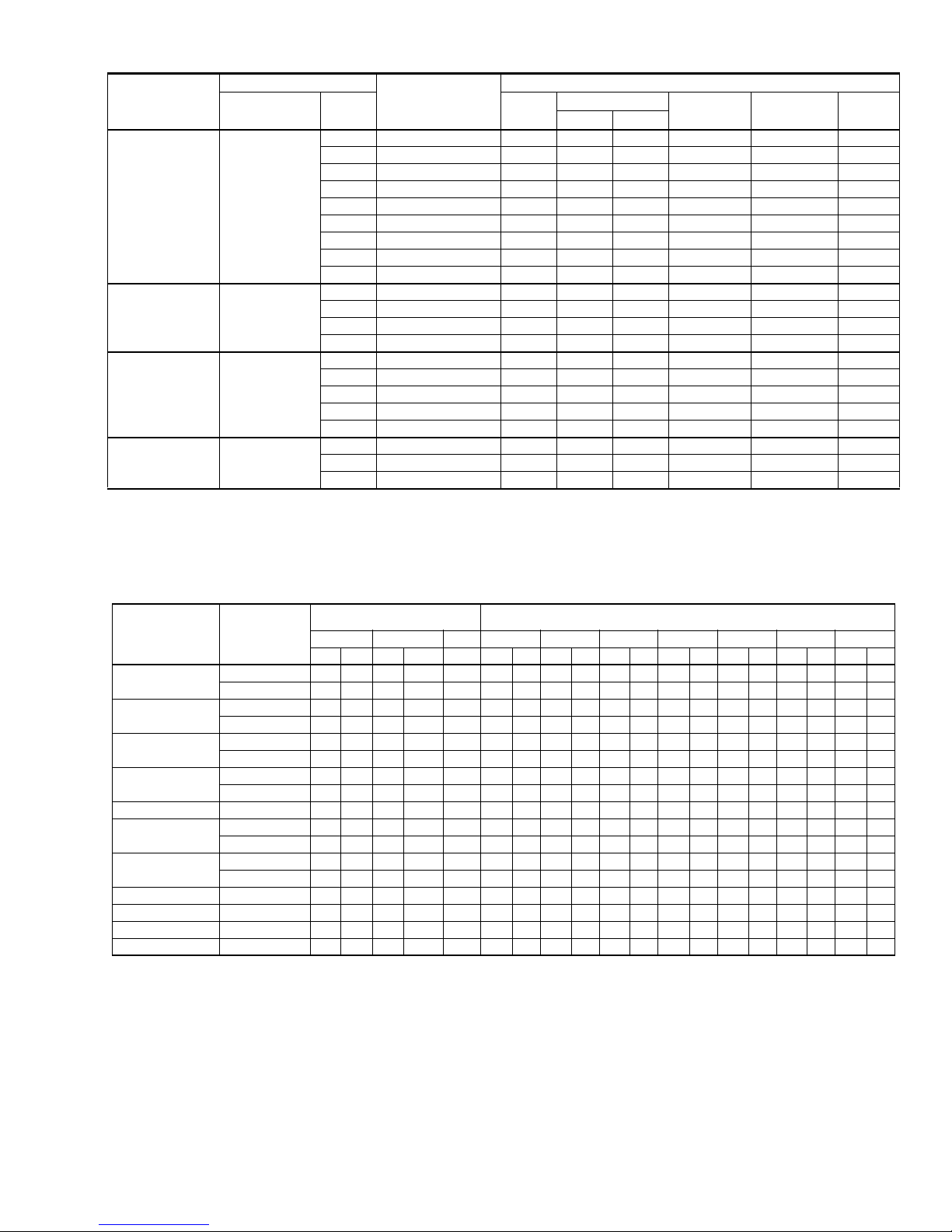
SOUND RATINGS*
UNIT
MODEL
018 80
024 80
030 80
036 82
042 82
048 77
060 82
*Rated in accordance with ARI Standard 270.
SOUND RATINGS
DECIBELS
A
B
All dimensions are in inches. They are subject to change without
notice. Certified dimensions will be provided upon request.
DIMENSIONS - 1 PHASE
UNIT
MODEL
018 19 35 23
024 25 35 23
030 25 35 23
036 25 35 23
042 27 37 27
048 33 37 27
060 39 37 27
1. Including fan guard.
DIMENSIONS
(INCHES)
1
A
B C Liquid Vapor
DIMENSIONS - 3 PHASE
UNIT
MODEL
036 25 35 23
048 33 37 27 7/8”
060 26 43 32 7/8”
090 32 43 32 1/2” 1-1/8”
1. Including fan guard.
DIMENSIONS
(INCHES)
1
A
B C Liquid Vapor
C
REFRIGERANT
CONNECTION
LINE SIZE
3/8”
REFRIGERANT
CONNECTION
LINE SIZE
3/8”
3/4”
7/8”
3/4”
Unitary Products Group 9
Page 10
036-21318-002 Rev. A (0106)
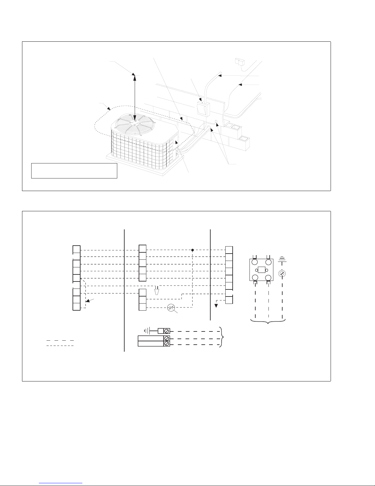
TYPICAL INSTALLATION
60” OVERHEAD
CLEARANCE
10” CLEARANCE
COIL AREA
NOTE: ALL OUTDOOR WIRING
MUST BE WEATHERPROOF.
TYPICAL FIELD WIRING - 1 PH
ALL FIELD WIRING TO BE IN ACCORDANCE WITH ELECTRIC CODE (NEC) AND/OR LOCAL CODES
THERMOSTAT
R
BorC
Y
O
W
LorX
G
T
E
1
JUMPER TERMINALS E AND W TO HEAT
ON FIRST STAGE DURING EMERGENCY HEAT.
2
TERMINAL NOT USED ON ALL THERMOSTATS.
POWER WIRING
24V CONTROL WIRING
(NEC CLASS 2)
1
2
2
FIELD
INSTALLED
JUMPER
3
CHECK THE LOW VOLTAGE TERMINAL BLOCK ON THE INDOOR UNIT FOR THE ACTUAL ARRANGEMENT OF THE TERMINALS.
4
CONNECT POWER WIRING TO TERMINAL BLOCK 3TB ON UNITS WITHOUT ELECTRIC HEAT OR CIRCUIT BREAKER.
5
GRAY FOR USE WITH OPTIONAL OUTDOOR THERMOSTAT KITS.
MINIMUM 24” SERVICE ACCESS
CLEARANCE ON ONE SIDE
WEATHERPROOF
DISCONNECT
SWITCH
CONTROL ACCESS PANEL
INDOOR UNIT
LOW VOLTAGE TERMINAL BLOCK
IN AIR HANDLER WITH ELECTRIC HEAT
R
C
Y
O
W2
G
W1
BK
DEHUMIDIFICATION CONTROL CONNECTION
(Humidistat* Jumper must be removed)
GND.
LUG
CIRCUIT
BREAKER***
3,4
THERMOSTAT
SEAL OPENING(S) WITH
PERMAGUM OR EQUIVALENT
OUTDOOR UNIT
DEFROST
CONTROL
RED
R
BLK
C
YEL
Y
ORG
O
BRN
W
PUR
X/L
WHT
/66
W1
5
GRY
CC
TO FURNACE OR
AIR HANDLER
TERMINAL BLOCK
NEC CLASS 1 WIRING
NEC CLASS 2 WIRING
TO INDOOR COIL
CONTACTOR
T2
T1
M
L2
L1
POWER WIRING
208/230-1-60
230-1-50
SCREW
GND.
10 Unitary Products Group
Page 11

TYPICAL FIELD WIRING - 3 PH (036 - 060)
ALL FIELD WIRING TO BE IN ACCORDANCE WITH ELECTRIC CODE (NEC) AND/OR LOCAL CODES
THERMOSTAT
LOW VOLTAGE TERMINAL BLOCK
IN AIR HANDLER WITH ELECTRIC HEAT
R
BorC
Y
O
W
LorX
G
T
E
1
JUMPER TERMINALS E AND W TOHEAT
ON FIRST STAGE DURING EMERGENCY HEAT.
2
TERMINAL NOT USED ON ALL THERMOSTATS.
1
2
2
POWER WIRING
24V CONTROL WIRING
(NEC CLASS 2)
FIELD
INSTALLED
JUMPER
GND.
LUG
3
CHECK THE LOW VOLTAGE TERMINAL BLOCK ON THE INDOOR UNIT FOR THE ACTUAL ARRANGEMENT OF THE TERMINALS.
4
CONNECT POWER WIRING TO TERMINAL BLOCK 3TB ON UNITS WITHOUT ELECTRIC HEAT OR CIRCUIT BREAKER.
5
GRAY FOR USE WITH OPTIONAL OUTDOOR THERMOSTAT KITS.
INDOOR UNIT
R
BorC
Y
O
W2
G
W1
036-21318-002 Rev. A (0106)
3,4
OUTDOOR UNIT
DEFROST
CONTROL
RED
R
BLK
C
YEL
Y
ORG
O
BRN
W
PUR
X
WHT
/66
W1
5
GRY
CC
POWER
SUPPLY
208/230-3-60
460-3-50
CONTACTOR
T3
T2
M
L3
L2
POWER WIRING
208/230-3-60
460-3-50
T1
L1
GND.
SCREW
TYPICAL FIELD WIRING - 3 PH (090)
ALL FIELD WIRING TO BE IN ACCORDANCE WITH ELECTRIC CODE (NEC) AND/OR LOCAL CODES
THERMOSTAT
R
BorC
Y
O
W
X
G
T
E
1
JUMPER TERMINALS E AND W TOHEAT
ON FIRST STAGE DURING EMERGENCY HEAT.
2
TERMINAL NOT USED ON ALL THERMOSTATS.
3
TERMINAL NOT USED ON ALL THERMOSTATS.
1
2
2
FIELD
INSTALLED
JUMPER
POWER WIRING
24V CONTROL WIRING
(NEC CLASS 2)
3
CHECK THE LOW VOLTAGE TERMINAL BLOCK ON THE INDOOR UNIT FOR THE ACTUAL ARRANGEMENT OF THE TERMINALS.
4
CONNECT POWER WIRING TO TERMINAL BLOCK 3TB ON UNITS WITHOUT ELECTRIC HEAT OR CIRCUIT BREAKER.
5
REQUIRED ON ALL ELECTRIC HEAT
INDOOR UNIT
LOW VOLTAGE TERMINAL BLOCK
IN AIR HANDLER WITH ELECTRIC HEAT
R
C
Y
O
W
X
GND.
LUG
53
G
60
60
5
FIELD
INSTALLED
JUMPER
3,4
DEFROST
CONTROL
RED
BLK
YEL
ORG
BRN
PUR
WHT
208/230-3-60
R
C
Y
O
W
X
/66
W1
POWER
SUPPLY
460-3-50
CONTACTOR
T3
T2
M
L3
L2
POWER WIRING
208/230-3-60
460-3-50
T1
L1
GND.
SCREW
OUTDOOR UNIT
Unitary Products Group 11
Page 12

036-21318-002 Rev. A (0106)
COOLING PERFORMANCE DATA
AIR CONDITIONER MODEL NO. EBBA-F018S
INDOOR COIL MODEL NO. F2RP/F2FP018
CONDENSER
ENTERING AIR
TEMPERATURE
75
85
95
105
115
125
ALL CAPACITIES INCLUDE INDOOR FAN HEAT AT 1250 BTUH/1000 CFM.
NOTE:
ID CFM 500 650 800
ID DB (°F) 85 80 70 85 80 70 85 80 70
ID WB (°F) 72 67 57 72 67 57 72 67 57
T.C. 20.8 18.3 15.1 22.4 19.4 16.0 23.1 20.0 16.6
S.C. 11.7 11.0 9.8 13.8 12.7 11.5 15.5 14.2 12.8
KW 1.71 1.91 1.83 1.73 1.94 1.86 1.76 1.98 1.88
T.C. 19.4 17.2 14.5 20.5 18.2 15.5 21.1 18.7 16.0
S.C. 11.4 10.8 10.0 13.4 12.5 11.7 15.0 14.0 13.0
KW 1.78 1.90 1.92 1.80 1.93 1.95 1.83 1.96 1.97
T.C. 17.9 16.1 13.8 18.7 17.0 15.0 19.0 17.5 15.5
S.C. 11.2 10.5 10.2 13.0 12.3 11.9 14.5 13.8 13.3
KW 1.85 1.89 2.02 1.87 1.92 2.04 1.89 1.94 2.06
T.C. 15.5 14.9 12.5 16.3 15.7 13.3 16.6 16.3 13.8
S.C. 10.5 10.0 9.3 12.3 11.9 11.0 13.8 13.4 12.4
KW 2.08 1.99 2.02 2.11 2.02 2.04 2.13 2.04 2.06
T.C. 13.0 13.8 11.2 13.9 14.5 11.7 14.3 15.0 12.0
S.C. 9.8 9.5 8.4 11.7 11.6 10.1 13.1 13.1 11.5
KW 2.32 2.09 2.03 2.35 2.12 2.05 2.36 2.13 2.07
T.C. 10.5 12.6 9.8 11.6 13.3 10.0 11.9 13.8 10.3
S.C. 9.2 9.0 7.5 11.0 11.2 9.3 12.4 12.7 10.5
KW 2.56 2.19 2.04 2.59 2.22 2.06 2.60 2.23 2.07
Multipliers for determining the performance with other indoor sections.
NOTE: For dry bulb temperatures different than those listed (between 73-87 F), sensible capacity increases by 1060 BTUH per 1000 CFM per degree above the
listed temperature and decreases by 1060 BTUH per 1000 CFM per degree belowthe listed temperature.
Air Handler Coil
N1AHB0806 G2FD024(S,H)17 1.05 1.04 1.04
F2RP/F2FP024 1.05 1.01 1.04
G1FA024S14,17 1.04 1.03 1.04
G1FA030S14 1.05 1.05 1.04
G1HD024 1.06 1.05 1.05
G1NA030S17H 1.06 1.10 1.02
G1NA030S21B 1.06 1.10 1.02
G1UA024S14,17 1.04 1.03 1.04
G1UA030S14 1.05 1.05 1.04
G2FD024(S,H)14,17 1.05 1.04 1.04
T.C. S.C. KW
12 Unitary Products Group
Page 13

COOLING PERFORMANCE DATA
AIR CONDITIONER MODEL NO. EBBA-F024S
INDOOR COIL MODEL NO. F2RP/F2FP030
CONDENSER
ENTERING AIR
TEMPERATURE
75
85
95
105
115
125
ALL CAPACITIES INCLUDE INDOOR FAN HEAT AT 1250 BTUH/1000 CFM.
NOTE:
ID CFM 650 850 1050
ID DB (°F) 85 80 75 70 85 80 75 70 85 80 75 70
ID WB (°F) 72 67 62 57 72 67 62 57 72 67 62 57
T.C. 26.6 24.3 22.4 20.0 27.0 24.7 22.7 20.3 27.1 24.8 22.8 20.9
S.C. 15.7 15.7 15.0 15.8 16.4 16.4 15.8 16.6 16.8 16.8 16.2 17.4
KW 2.20 2.12 2.06 1.97 2.21 2.13 2.07 1.99 2.21 2.14 2.08 2.01
T.C. 25.7 23.5 21.5 19.4 26.1 23.8 21.9 19.8 26.2 23.9 22.0 20.0
S.C. 15.8 15.8 15.1 16.1 16.7 16.7 16.0 17.0 17.1 17.1 16.5 17.4
KW 2.35 2.25 2.18 2.11 2.37 2.27 2.19 2.12 2.37 2.27 2.20 2.12
T.C. 23.9 21.7 20.1 17.9 24.2 22.0 20.4 18.2 24.3 22.1 20.5 18.6
S.C. 15.5 15.4 15.0 15.5 16.5 16.5 15.9 16.6 17.0 17.0 16.4 17.1
KW 2.50 2.40 2.30 2.21 2.51 2.41 2.33 2.22 2.52 2.42 2.34 2.25
T.C. 21.7 19.7 18.2 16.4 21.9 20.1 18.5 16.8 22.1 20.2 18.6 17.0
S.C. 15.0 15.0 14.3 15.1 16.1 16.2 15.2 15.5 16.7 16.6 15.6 15.7
KW 2.64 2.51 2.42 2.32 2.65 2.53 2.44 2.35 2.66 2.53 2.45 2.37
T.C. 19.5 17.8 16.3 14.8 19.8 18.1 16.7 15.2 19.9 18.1 17.0 15.4
S.C. 14.4 14.3 13.6 13.7 15.5 15.4 14.5 14.1 15.9 15.8 14.7 14.2
KW 2.74 2.61 2.51 2.41 2.76 2.62 2.54 2.45 2.77 2.64 2.56 2.46
T.C. 17.3 15.9 14.5 13.2 17.7 16.1 15.0 13.6 17.7 16.0 15.3 13.8
S.C. 13.8 13.6 12.9 12.2 14.9 14.6 13.7 12.7 15.1 15.0 13.7 12.7
KW 2.84 2.72 2.61 2.50 2.87 2.72 2.65 2.55 2.88 2.74 2.68 2.55
036-21318-002 Rev. A (0106)
Multipliers for determining the performance with other indoor sections.
NOTE: For dry bulb temperatures different than those listed (between 73-87 F), sensible capacity increases by 1060 BTUH per 1000 CFM per degree above the
listed temperature and decreases by 1060 BTUH per 1000 CFM per degree belowthe listed temperature.
Air Handler Coil
N1AHB0806 G2FD030(S,H)17 1.00 0.96 1.01
F2RP/F2FP024 0.97 0.98 0.98
G1FA030S14 0.98 0.98 1.00
G1FA036S17,21 1.00 0.96 1.01
G1HD024 0.98 0.98 0.99
G1NA030S17H 1.02 0.96 1.01
G1NA030S21B 1.02 0.96 1.01
G1UA030S14 0.98 0.98 1.00
G1UA036S17,21 1.00 0.96 1.01
G2FD024(S,H)14,17 0.97 0.94 0.98
G2FD030(S,H)17 1.00 0.96 1.01
G2FD035(S,H)14 1.00 0.96 1.01
T.C. S.C. KW
Unitary Products Group 13
Page 14

036-21318-002 Rev. A (0106)
COOLING PERFORMANCE DATA
AIR CONDITIONER MODEL NO. EABA-F030S
INDOOR COIL MODEL NO. F2RP/F2FP036
CONDENSER
ENTERING AIR
TEMPERATURE
75
85
95
105
115
125
ALL CAPACITIES INCLUDE INDOOR FAN HEAT AT 1250 BTUH/1000 CFM.
NOTE:
ID CFM 850 1050 1250
ID DB (°F) 85 80 70 85 80 70 85 80 70
ID WB (°F) 72 67 57 72 67 57 72 67 57
T.C. 27.1 27.3 26.5 28.3 28.3 28.6 28.8 29.1 29.7
S.C. 19.7 19.9 19.1 20.9 20.9 21.2 21.4 21.7 22.3
KW 2.77 2.75 2.71 2.79 2.74 2.72 2.79 2.75 2.72
T.C. 27.3 26.9 26.9 29.1 28.4 27.9 30.0 29.8 29.3
S.C. 19.9 19.5 19.5 21.7 21.0 20.5 22.6 22.4 21.9
KW 2.95 2.90 2.86 2.98 2.91 2.87 2.99 2.93 2.88
T.C. 27.6 26.5 27.2 29.8 28.4 27.2 31.2 30.4 28.9
S.C. 20.2 19.1 19.8 22.4 21.0 19.8 23.8 23.0 21.5
KW 3.13 3.06 3.01 3.16 3.09 3.03 3.18 3.12 3.05
T.C. 26.6 25.6 25.4 29.0 27.7 26.5 30.6 29.6 28.2
S.C. 19.2 18.2 18.0 21.6 20.3 19.1 23.2 22.2 20.8
KW 3.29 3.22 3.15 3.32 3.25 3.18 3.34 3.28 3.20
T.C. 25.5 24.7 23.5 28.1 27.0 25.8 30.0 28.8 27.6
S.C. 18.1 17.3 16.1 20.7 19.6 18.4 22.6 21.4 20.2
KW 3.44 3.38 3.29 3.47 3.41 3.33 3.50 3.44 3.35
T.C. 24.5 23.9 21.7 27.3 26.4 25.0 29.4 28.0 26.9
S.C. 17.1 16.5 14.3 19.9 19.0 17.6 22.0 20.6 19.5
KW 3.60 3.53 3.43 3.63 3.56 3.48 3.66 3.59 3.50
Multipliers for determining the performance with other indoor sections.
NOTE: For dry bulb temperatures different than those listed (between 73-87 F), sensible capacity increases by 1060 BTUH per 1000 CFM per degree above the
listed temperature and decreases by 1060 BTUH per 1000 CFM per degree belowthe listed temperature.
Air Handler Coil
N1AHB1206 G2FD030(S,H)17 0.97 0.94 1.00
F2RP/F2FP030 0.98 1.00 1.00
G1FA036S14 0.98 0.99 1.01
G1FA036S17,21 0.97 0.97 1.00
G1HD036 0.98 1.00 1.00
G1NA030S17H 1.00 0.99 1.00
G1NA030S21B 1.00 0.99 1.00
G1UA036S14 0.98 0.99 1.01
G1UA036S17,21 0.97 0.94 1.00
G2FD030(S,H)17 0.97 0.94 1.00
G2FD035(S,H)14 0.97 0.94 1.00
G2FD036(S,H)17 0.98 0.95 1.00
G2FD036(S,H)21 0.99 0.95 1.00
T.C. S.C. KW
14 Unitary Products Group
Page 15

COOLING PERFORMANCE DATA
AIR CONDITIONER MODEL NO. EABA-F036S, EABA-(T,W)036S)
INDOOR COIL MODEL NO. F2RP/F2FP036
CONDENSER
ENTERING AIR
TEMPERATURE
75
85
95
105
115
125
ALL CAPACITIES INCLUDE INDOOR FAN HEAT AT 1250 BTUH/1000 CFM.
NOTE:
ID CFM 1000 1250 1400
ID DB (°F) 85 80 75 70 85 80 75 70 85 80 75 70
ID WB (°F) 72 67 62 57 72 67 62 57 72 67 62 57
T.C. 38.1 35.0 32.5 29.4 38.6 35.5 32.9 29.9 38.8 35.7 33.2 30.2
S.C. 22.9 22.9 22.1 23.6 24.1 24.2 23.4 24.8 24.9 24.9 24.1 25.5
KW 3.15 3.08 3.02 2.94 3.16 3.10 3.03 2.96 3.17 3.10 3.04 2.97
T.C. 37.6 34.6 32.0 28.9 38.1 35.1 32.7 29.4 38.3 35.3 33.0 29.7
S.C. 23.3 23.4 22.6 23.9 24.8 24.9 24.1 25.3 25.7 25.7 25.0 26.1
KW 3.39 3.30 3.22 3.12 3.40 3.32 3.24 3.14 3.41 3.33 3.25 3.15
T.C. 36.2 33.3 30.9 27.7 36.7 33.7 31.4 28.3 36.8 34.0 31.6 28.6
S.C. 23.3 23.3 22.6 23.7 24.9 24.9 24.0 25.4 25.8 25.9 24.9 26.2
KW 3.71 3.60 3.51 3.38 3.72 3.62 3.53 3.40 3.74 3.64 3.55 3.42
T.C. 34.4 31.5 29.2 26.3 34.7 32.0 29.6 26.8 35.0 32.2 29.9 27.3
S.C. 22.9 22.9 22.1 23.3 24.5 24.5 23.5 24.7 25.6 25.5 24.6 25.5
KW 4.03 3.90 3.79 3.63 4.06 3.93 3.82 3.67 4.06 3.94 3.82 3.71
T.C. 32.2 29.6 27.4 24.7 32.6 30.0 27.8 25.5 32.8 30.2 28.1 25.8
S.C. 22.2 22.2 21.4 22.4 23.9 23.8 22.9 23.8 24.8 24.8 23.8 24.1
KW 4.34 4.19 4.05 3.88 4.37 4.22 4.09 3.93 4.38 4.24 4.10 3.96
T.C. 30.0 27.7 25.6 23.1 30.5 28.0 26.0 24.2 30.6 28.2 26.3 24.3
S.C. 21.5 21.5 20.6 21.5 23.3 23.1 22.2 22.9 24.0 24.1 23.1 22.7
KW 4.65 4.48 4.31 4.13 4.68 4.51 4.36 4.19 4.70 4.54 4.38 4.21
036-21318-002 Rev. A (0106)
Multipliers for determining the performance with other indoor sections.
NOTE: For dry bulb temperatures different than those listed (between 73-87 F), sensible capacity increases by 1060 BTUH per 1000 CFM per degree above the
listed temperature and decreases by 1060 BTUH per 1000 CFM per degree belowthe listed temperature.
1 Phase 3 Phase
Air Handler Coil
N1AHB1206 G2FD036(S,H)17 0.99 1.00 1.01
F2RP/F2FP042 1.00 1.00 1.00
G1FA048S21 1.01 0.99 1.01
G1HD036 0.98 0.99 1.00
G1HD048 1.04 1.04 1.02
G1NA036S17L 1.03 1.05 1.03
G1NA048S21D 1.03 1.05 1.04
G1UA048S21 1.01 0.99 1.01
G2FD036(S,H)17 0.99 1.00 1.01
G2FD036(S,H)21 1.00 0.98 0.99
G2FD042(S,H)21 1.01 1.02 1.01
G2FD046(S,H)17 1.02 1.03 1.01
T.C. S.C. KW
Air Handler Coil
N1AHC1646 G2FD042(S,H)21 1.01 1.02 1.01
F2RP/F2FP042 1.00 1.00 1.00
G1FA048S21 1.01 0.99 1.01
G1NA036S17L 1.03 1.05 1.03
G1NA048S21D 1.03 1.05 1.04
G1UA048S21 1.01 0.99 1.01
G2FD042(S,H)21 1.01 1.02 1.01
T.C. S.C. KW
Unitary Products Group 15
Page 16

036-21318-002 Rev. A (0106)
COOLING PERFORMANCE DATA
AIR CONDITIONER MODEL NO. EABA-F042S
INDOOR COIL MODEL NO. F2RP/F2FP042
CONDENSER
ENTERING AIR
TEMPERATURE
75
85
95
105
115
125
ALL CAPACITIES INCLUDE INDOOR FAN HEAT AT 1250 BTUH/1000 CFM.
NOTE:
ID CFM 1200 1400 1600
ID DB (°F) 85 80 70 85 80 70 85 80 70
ID WB (°F) 72 67 57 72 67 57 72 67 57
T.C. 44.8 42.1 38.8 45.8 43.0 40.4 46.2 43.5 40.9
S.C. 27.9 28.4 27.4 29.9 29.7 29.5 30.8 30.8 30.9
KW 3.74 3.69 3.63 3.76 3.71 3.66 3.78 3.73 3.67
T.C. 42.9 39.6 35.7 43.9 41.0 37.1 44.4 41.3 37.9
S.C. 27.7 27.4 26.0 29.7 29.3 28.1 30.7 30.7 29.8
KW 3.96 4.02 3.79 3.99 4.05 3.83 4.01 4.07 3.85
T.C. 41.1 37.1 32.7 42.0 39.0 33.9 42.5 39.1 34.9
S.C. 27.5 26.4 24.7 29.5 28.8 26.8 30.7 30.6 28.6
KW 4.18 4.35 3.95 4.22 4.38 4.00 4.24 4.41 4.03
T.C. 37.6 33.7 29.9 38.6 35.0 30.9 39.3 35.4 31.6
S.C. 26.3 24.9 23.4 28.4 27.2 25.4 30.1 29.0 27.2
KW 4.38 4.39 4.12 4.42 4.42 4.16 4.45 4.46 4.19
T.C. 34.2 30.2 27.1 35.2 31.0 27.8 36.0 31.8 28.3
S.C. 25.0 23.4 22.1 27.3 25.7 24.1 29.4 27.5 25.7
KW 4.58 4.42 4.28 4.62 4.47 4.32 4.66 4.50 4.35
T.C. 30.8 26.8 24.3 31.7 27.0 24.7 32.8 28.1 24.9
S.C. 23.8 21.9 20.9 26.2 24.1 22.8 28.7 25.9 24.2
KW 4.77 4.46 4.45 4.82 4.51 4.48 4.86 4.55 4.50
Multipliers for determining the performance with other indoor sections.
NOTE: For dry bulb temperatures different than those listed (between 73-87 F), sensible capacity increases by 1060 BTUH per 1000 CFM per degree above the
listed temperature and decreases by 1060 BTUH per 1000 CFM per degree belowthe listed temperature.
Air Handler Coil
N1AHC1606 G2FD048(S,H)21 1.03 1.04 1.00
F2FP048 1.01 1.01 0.99
G1FA048S21 1.01 1.00 0.98
G1HD048 1.01 1.16 0.99
G1NA048S21D 1.04 1.01 0.97
G1UA048S21 1.01 1.00 0.98
G2FD042(S,H)21 1.00 1.02 0.98
G2FD046(S,H)17 1.01 1.03 0.99
G2FD048(S,H)21,24 1.03 1.04 1.00
G2FD060(S,H)24 1.03 1.04 0.98
T.C. S.C. KW
16 Unitary Products Group
Page 17

COOLING PERFORMANCE DATA
AIR CONDITIONER MODEL NO. EBBA-F048S, EBBA-(T,W)048S
INDOOR COIL MODEL NO. F2FP048
CONDENSER
ENTERING AIR
TEMPERATURE
75
85
95
105
115
125
ALL CAPACITIES INCLUDE INDOOR FAN HEAT AT 1250 BTUH/1000 CFM.
NOTE:
ID CFM 1300 1450 1550
ID DB (°F) 85 80 75 70 85 80 75 70 85 80 75 70
ID WB (°F) 72 67 62 57 72 67 62 57 72 67 62 57
T.C. 52.3 48.3 45.0 40.6 53.0 49.0 45.7 41.3 53.4 49.4 46.1 41.9
S.C. 32.5 32.8 31.7 33.5 34.0 34.3 33.2 35.1 35.0 35.2 34.1 36.3
KW 4.14 4.07 4.02 3.95 4.16 4.08 4.04 3.97 4.17 4.09 4.05 3.97
T.C. 50.9 47.0 43.7 39.4 51.5 47.6 44.4 40.3 51.9 48.0 44.7 40.6
S.C. 32.4 32.6 31.6 33.3 34.0 34.2 33.2 35.1 35.2 35.4 34.2 36.2
KW 4.44 4.36 4.30 4.22 4.46 4.38 4.32 4.24 4.47 4.38 4.33 4.25
T.C. 48.8 45.0 41.8 37.9 49.2 45.5 42.4 38.4 49.6 45.8 42.7 38.7
S.C. 32.0 32.2 31.2 32.9 33.6 33.8 32.9 34.5 34.9 35.1 33.8 35.6
KW 4.87 4.79 4.73 4.64 4.90 4.81 4.74 4.66 4.91 4.81 4.76 4.67
T.C. 46.1 42.5 39.5 35.8 46.6 43.0 40.1 36.3 46.4 43.3 40.4 36.7
S.C. 31.0 31.1 30.1 32.0 32.9 32.9 31.9 33.7 33.8 34.3 32.9 35.1
KW 5.37 5.28 5.22 5.12 5.38 5.30 5.22 5.14 5.34 5.30 5.24 5.14
T.C. 43.2 39.9 37.0 33.5 43.6 40.3 37.6 34.2 43.8 40.6 37.9 35.0
S.C. 29.9 30.2 29.2 30.7 31.8 32.1 30.8 32.8 32.9 33.1 31.8 34.5
KW 5.90 5.80 5.74 5.66 5.90 5.80 5.76 5.66 5.92 5.83 5.78 5.68
T.C. 40.3 37.3 34.6 31.2 40.6 37.6 35.0 32.1 41.2 37.9 35.3 33.3
S.C. 28.8 29.3 28.2 29.4 30.7 31.3 29.7 31.9 32.0 31.9 30.8 33.9
KW 6.43 6.32 6.27 6.20 6.42 6.30 6.31 6.18 6.50 6.36 6.31 6.22
036-21318-002 Rev. A (0106)
Multipliers for determining the performance with other indoor sections.
NOTE: For dry bulb temperatures different than those listed (between 73-87 F), sensible capacity increases by 1060 BTUH per 1000 CFM per degree above the
listed temperature and decreases by 1060 BTUH per 1000 CFM per degree belowthe listed temperature.
1 Phase 3 Phase
Air Handler Coil
N1AHC1606 G2FD048(S,H)21 1.00 1.00 0.97
N1AHD2006 G2FD048(S,H)24 1.00 1.00 0.97
N1AHD2006 G2FD060(S,H)24 1.03 1.03 1.01
F2FP060 1.02 1.01 1.02
G1FA048S21 1.00 0.97 0.98
G1FA060S21,24 1.01 1.01 0.97
G1HD048 0.98 0.98 0.96
G1HD060 1.00 1.00 0.96
G1NA048S21D 0.99 0.93 0.95
G1UA048S21 1.00 0.97 0.98
G1UA060S21,24 1.01 1.01 0.97
G2FD048(S,H)21,24 1.00 1.00 0.97
G2FD060(S,H)24 1.01 1.01 0.96
T.C. S.C. KW
Air Handler Coil
N1AHC1646 G2FD048(S,H)21 1.00 1.00 0.97
N1AHD2046 G2FD048(S,H)24 1.00 1.00 0.97
F2FP060 1.02 1.01 1.02
G1FA048S21 1.00 0.97 0.98
G1NA048S21D 0.99 0.93 0.95
G1UA048S21 1.00 0.97 0.98
G2FD048(S,H)21,24 1.00 1.00 0.97
T.C. S.C. KW
Unitary Products Group 17
Page 18

036-21318-002 Rev. A (0106)
COOLING PERFORMANCE DATA
AIR CONDITIONER MODEL NO. EABA-F060S
INDOOR COIL MODEL NO. F2FP060
CONDENSER
ENTERING AIR
TEMPERATURE
75
85
95
105
115
125
ALL CAPACITIES INCLUDE INDOOR FAN HEAT AT 1250 BTUH/1000 CFM.
NOTE:
ID CFM 1550 1750 1950
ID DB (°F) 85 80 75 70 85 80 75 70 85 80 75 70
ID WB (°F) 72 67 62 57 72 67 62 57 72 67 62 57
T.C. 62.6 57.9 53.9 48.8 63.6 58.8 54.9 49.7 64.1 59.4 55.4 50.3
S.C. 39.7 40.1 38.8 41.2 42.3 42.6 41.3 43.6 44.0 44.4 43.0 45.4
KW 5.15 5.08 5.03 4.94 5.16 5.09 5.05 4.96 5.17 5.10 5.06 4.98
T.C. 60.0 55.5 51.8 46.7 61.0 56.4 52.7 47.7 61.4 56.8 53.2 48.3
S.C. 38.8 39.1 38.0 40.1 41.3 41.6 40.3 42.5 42.8 43.2 42.0 44.4
KW 5.61 5.54 5.48 5.39 5.63 5.55 5.51 5.41 5.64 5.57 5.53 5.42
T.C. 57.7 53.3 49.6 44.8 58.4 54.0 50.3 45.7 58.8 54.4 51.1 46.3
S.C. 38.0 38.3 37.1 39.1 40.2 40.5 39.3 41.4 41.9 42.2 41.1 43.3
KW 6.33 6.25 6.20 6.09 6.35 6.28 6.22 6.11 6.36 6.29 6.23 6.12
T.C. 55.1 50.9 47.4 42.8 55.6 51.5 48.2 43.6 56.0 51.8 48.7 44.1
S.C. 37.1 37.4 36.1 38.0 39.3 39.5 38.5 40.5 40.9 41.1 40.1 42.2
KW 7.16 7.08 7.02 6.90 7.19 7.11 7.04 6.93 7.20 7.13 7.06 6.94
T.C. 52.0 48.1 44.8 40.4 52.5 48.6 45.6 41.2 52.9 49.2 46.0 41.8
S.C. 35.6 36.0 34.8 36.8 38.0 38.3 37.3 39.3 39.7 40.4 38.8 40.9
KW 8.13 8.02 7.95 7.82 8.14 8.04 7.97 7.84 8.15 8.05 7.99 7.86
T.C. 48.9 45.3 42.1 38.0 49.4 45.7 42.9 38.8 49.8 46.6 43.2 39.5
S.C. 34.2 34.7 33.6 35.5 36.7 37.1 36.2 38.1 38.5 39.7 37.4 39.6
KW 9.10 8.96 8.89 8.74 9.09 8.97 8.91 8.76 9.10 8.97 8.93 8.79
Multipliers for determining the performance with other indoor sections.
NOTE: For dry bulb temperatures different than those listed (between 73-87 F), sensible capacity increases by 1060 BTUH per 1000 CFM per degree above the
listed temperature and decreases by 1060 BTUH per 1000 CFM per degree belowthe listed temperature.
Air Handler Coil
N1AHD2006 G2FD060(S,H)24 1.01 0.97 0.97
G1FA060S21,24 1.01 0.97 0.98
G1HD060 1.01 0.84 0.99
G1NA060S24T 0.99 0.88 0.95
G1UA060S21,24 1.01 0.97 0.98
G2FD060(S,H)24 1.01 0.97 0.98
T.C. S.C. KW
18 Unitary Products Group
Page 19

COOLING PERFORMANCE DATA
AIR CONDITIONER MODEL NO. EABA-(T,W)060S)
INDOOR COIL MODEL NO. G2FD060(S,H)24
CONDENSER
ENTERING AIR
TEMPERATURE
65
75
85
95
105
115
ALL CAPACITIES INCLUDE INDOOR FAN HEAT AT 1250 BTUH/1000 CFM.
NOTE:
ID CFM 1600 1800 2000
ID DB (°F) 85 80 75 85 80 75 85 80 75
ID WB (°F) 71 67 63 71 67 63 71 67 63
T.C. 63.0 61.1 60.7 62.9 60.9 61.1 62.9 60.6 61.4
S.C. 39.6 39.7 40.3 41.6 41.5 42.2 43.7 43.3 44.1
KW 3.71 3.66 3.68 3.71 3.66 3.67 3.71 3.67 3.67
T.C. 62.3 59.8 57.9 62.5 60.0 58.5 62.6 60.1 59.0
S.C. 39.6 39.3 39.1 41.8 41.3 41.1 43.9 43.3 43.1
KW 4.20 4.14 4.12 4.21 4.15 4.13 4.21 4.16 4.13
T.C. 61.7 58.5 55.1 62.0 59.1 55.9 62.3 59.6 56.6
S.C. 39.6 38.9 38.0 41.9 41.1 40.1 44.2 43.3 42.2
KW 4.70 4.63 4.57 4.71 4.64 4.58 4.72 4.65 4.60
T.C. 61.0 57.2 52.3 61.5 58.2 53.3 62.0 59.1 54.2
S.C. 39.6 38.5 36.8 42.0 40.9 39.0 44.4 43.3 41.2
KW 5.19 5.11 5.01 5.21 5.13 5.04 5.22 5.14 5.06
T.C. 58.3 53.9 49.1 59.1 54.7 49.9 60.0 55.6 50.7
S.C. 38.5 37.2 35.4 41.0 39.6 37.6 43.6 41.9 39.8
KW 5.78 5.67 5.55 5.80 5.69 5.57 5.82 5.71 5.60
T.C. 55.5 50.5 45.9 56.8 51.3 46.5 58.0 52.1 47.1
S.C. 37.4 35.9 34.0 40.1 38.2 36.2 42.7 40.5 38.3
KW 6.36 6.22 6.08 6.39 6.25 6.11 6.41 6.27 6.13
036-21318-002 Rev. A (0106)
Multipliers for determining the performance with other indoor sections.
NOTE: For dry bulb temperatures different than those listed (between 73-87 F), sensible capacity increases by 1060 BTUH per 1000 CFM per degree above the
listed temperature and decreases by 1060 BTUH per 1000 CFM per degree belowthe listed temperature.
Air Handler Coil
N1AHD2046 G2FD060(S,H)24 1.00 1.00 1.00
F2FP060 G1FA060S21,24 0.98 0.98 1.02
G1FA060S21,24 1.00 1.00 1.00
G1UA060S21,24 1.00 1.00 1.00
T.C. S.C. KW
Unitary Products Group 19
Page 20

036-21318-002 Rev. A (0106)
COOLING PERFORMANCE DATA
AIR CONDITIONER MODEL NO. EABA-(T,W)090S
INDOOR COIL MODEL NO. FCEH090
CONDENSER
ENTERING AIR
TEMPERATURE
75
85
95
105
115
125
ALL CAPACITIES ARE NET WITH INDOOR FAN HEAT ALREADY DEDUCTED AT 1250 BTUH/1000 CFM.
NOTE:
ID CFM 2400 3000 3600
ID DB (°F) 85 80 70 85 80 70 85 80 70
ID WB (°F) 72 67 57 72 67 57 72 67 57
T.C. 103.9 94.3 88.5 107.3 98.0 92.1 110.6 101.8 95.7
S.C. 86.2 82.8 81.1 95.3 91.5 89.1 104.4 100.3 97.2
K.W 8.13 8.14 7.84 8.22 8.18 7.94 8.30 8.22 8.03
T.C. 99.6 91.2 85.5 103.1 94.6 88.8 106.5 98.0 92.1
S.C. 84.1 80.9 79.0 93.4 89.5 87.2 102.8 98.1 95.4
K.W 8.91 8.83 8.61 8.98 8.89 8.69 9.06 8.94 8.78
T.C. 95.3 88.2 82.4 98.8 91.2 85.5 102.3 94.2 88.6
S.C. 82.0 79.0 76.8 91.6 87.4 85.2 101.1 95.8 93.6
K.W 9.68 9.53 9.38 9.75 9.60 9.45 9.82 9.66 9.53
T.C. 91.1 84.2 78.6 94.4 86.9 81.5 97.6 89.5 84.5
S.C. 79.4 76.8 74.6 89.0 85.0 82.9 98.7 93.3 91.1
K.W 10.62 10.47 10.33 10.70 10.55 10.40 10.78 10.63 10.46
T.C. 86.9 80.2 74.7 89.9 82.5 77.6 92.9 84.8 80.5
S.C. 76.7 74.6 72.5 86.5 82.7 80.5 96.3 90.8 88.5
K.W 11.55 11.41 11.29 11.64 11.50 11.34 11.74 11.60 11.40
T.C. 82.7 76.2 70.8 85.4 78.2 73.6 88.1 80.1 76.4
S.C. 74.1 72.4 70.3 84.0 80.4 78.2 93.8 88.3 86.0
K.W 12.48 12.35 12.24 12.59 12.46 12.29 12.69 12.57 12.33
20 Unitary Products Group
Page 21

HEATING PERFORMANCE DATA
CONDENSING UNIT MODEL NO. EBBA-F018S
EVAPORATOR COIL MODEL NO. F2RP/F2FP018
AIR TEMP.
ENTERING
OUTDOOR
UNIT
60
47
40
30
17
10
NOTE:
ALL CAPACITIES INCLUDE INDOOR FAN HEAT AT 1250 BTUH/1000 CFM.
AIR TEMP.
ENTERING
INDOOR
COIL
60 21.11.703.6621.81.703.7622.01.574.11
70 20.11.733.4221.01.743.5321.31.623.86
80 19.01.763.1620.01.793.2820.61.683.60
60 17.81.623.2218.01.643.2118.11.543.43
70 16.51.672.9117.01.692.9617.31.583.21
80 15.21.722.6016.01.742.7016.41.632.97
60 13.61.303.0515.51.602.8416.11.503.15
70 12.61.492.4914.51.642.5914.41.542.73
80 11.6 1.98 1.73 13.5 1.70 2.34 12.7 1.87 2.00
60 13.11.542.5013.51.552.5513.21.422.72
70 12.01.582.2212.41.602.2812.51.492.46
80 10.8 1.62 1.94 11.4 1.66 2.01 11.8 1.57 2.21
60 9.7 1.431.9910.21.452.0610.41.372.21
70 8.6 1.51 1.66 9.1 1.50 1.78 9.3 1.46 1.88
80 7.5 1.61 1.36 8.0 1.56 1.50 8.3 1.55 1.58
60 8.1 1.35 1.77 8.6 1.38 1.82 8.9 1.30 2.01
70 6.9 1.39 1.46 7.5 1.43 1.53 7.9 1.35 1.71
80 5.6 1.43 1.16 6.3 1.48 1.25 6.9 1.41 1.43
MBTUH
500 650 800
KW C.O.P. MBTUH K C.O.P. MBTUH KW C.O.P.
036-21318-002 Rev. A (0106)
ID CFM
Multipliers for determining the performance with other indoor sections.
Air Handler Coil
N1AHB0806 G2FD024(S,H)14,17 1.00 0.98 1.02
F2RP/F2FP024 1.00 0.98 1.01
G2FD024(S,H)14,17 1.00 0.98 1.02
G1HD024 1.01 0.98 1.03
G1NA030S17H 1.01 1.01 1.00
G1NA030S21B 1.01 1.01 1.00
G1UA024S14,17 0.99 0.99 1.00
G1FA024S14,17 0.99 0.99 1.00
G1UA030S14 1.00 0.98 1.02
G1FA030S14 1.00 0.98 1.02
MBH KW COP
Unitary Products Group 21
Page 22

036-21318-002 Rev. A (0106)
HEATING PERFORMANCE DATA
CONDENSING UNIT MODEL NO. EBBA-F024S
EVAPORATOR COIL MODEL NO. F2RP/F2FP030
AIR TEMP.
ENTERING
OUTDOOR
UNIT
60
47
40
30
17
10
ALL CAPACITIES INCLUDE INDOOR FAN HEAT AT 1250 BTUH/1000 CFM.
NOTE:
AIR TEMP.
ENTERING
INDOOR
COIL
60 27.42.014.0027.61.984.0927.11.794.44
70 26.22.073.7226.82.043.8526.61.864.20
80 25.12.263.2626.12.243.4126.22.053.74
60 22.81.913.4922.81.953.4223.31.813.77
70 21.61.973.2222.02.023.2022.71.883.55
80 20.42.122.8221.22.182.8422.22.053.18
60 17.61.613.2020.01.962.9920.81.843.31
70 16.71.832.6719.22.022.7819.01.902.93
80 15.82.521.8418.42.172.4817.32.382.13
60 16.41.862.5916.81.872.6416.51.722.82
70 15.31.892.3716.01.922.4416.11.792.63
80 14.31.982.1115.12.022.1915.61.912.40
60 12.01.702.0712.41.762.0612.81.642.30
70 11.0 1.71 1.88 11.5 1.79 1.88 12.0 1.66 2.12
80 10.0 1.72 1.71 10.6 1.82 1.70 11.2 1.68 1.94
60 9.7 1.641.7410.11.671.7810.51.561.97
70 8.5 1.63 1.53 9.2 1.67 1.61 9.3 1.58 1.73
80 7.4 1.59 1.36 8.2 1.64 1.47 8.2 1.57 1.54
MBTUH KW C.O.P. MBTUH KW C.O.P. MBTUH KW C.O.P.
ID CFM
650 850 1050
Multipliers for determining the performance with other indoor sections.
Air Handler Coil
N1AHB0806 G2FD030(S,H)17 0.94 1.04 0.91
F2FP024 0.92 1.01 0.91
G2FD035(S,H)14 0.94 1.04 0.91
G2FD030(S,H)17 0.94 1.04 0.91
G2FD024(S,H)14,17 0.93 1.01 0.92
G1HD024 0.93 1.03 0.91
G1NA030S17H 0.98 1.04 0.94
G1NA030S21B 0.98 1.04 0.94
G1UA030S14 0.93 1.01 0.92
G1UA036S17,21 0.94 1.04 0.91
G1FA030S14 0.93 1.01 0.92
G1FA036S17,21 0.94 1.04 0.91
MBH KW COP
22 Unitary Products Group
Page 23

HEATING PERFORMANCE DATA
CONDENSING UNIT MODEL NO EABA-F030S
EVAPORATOR COIL MODEL NO F2RP/F2FP036
AIR TEMP.
ENTERING
OUTDOOR
UNIT
60
47
40
30
17
10
ALL CAPACITIES INCLUDE INDOOR FAN HEAT AT 1250 BTUH/1000 CFM.
NOTE:
AIR TEMP.
ENTERING
INDOOR
COIL
60 35.42.723.8235.72.713.8735.92.693.91
70 33.92.823.5335.12.833.6435.72.843.69
80 32.52.903.2934.72.933.4835.62.953.54
60 29.62.633.3129.92.633.3430.12.633.35
70 28.02.723.0229.02.743.1029.52.763.14
80 26.52.802.7728.22.842.9229.02.872.96
60 24.72.502.9025.42.542.9425.62.562.93
70 23.32.602.6324.12.632.6924.42.662.69
80 22.02.712.3822.92.732.4623.22.762.47
60 21.52.382.6522.32.412.7222.72.442.73
70 19.72.432.3720.62.472.4521.12.512.47
80 17.92.512.0918.92.562.1619.52.612.19
60 17.52.362.1717.72.402.1718.02.472.14
70 15.82.421.9116.32.471.9416.72.531.94
80 14.12.491.6714.82.531.7215.42.591.74
60 14.42.181.9415.22.232.0015.72.292.01
70 13.02.221.7213.62.271.7714.22.331.79
80 11.6 2.25 1.51 12.0 2.30 1.53 12.6 2.36 1.57
MBTUH KW C.O.P. MBTUH KW C.O.P. MBTUH KW C.O.P.
850 1050 1250
036-21318-002 Rev. A (0106)
ID CFM
Multipliers for determining the performance with other indoor sections.
Air Handler Coil
N1AHB1206 G2FD030(S,H)17 1.01 1.01 0.99
F2RP/F2FP030 0.99 0.99 1.00
G2FD030(S,H)17 1.01 1.01 0.99
G2FD035(S,H)14 1.01 1.01 0.99
G2FD036(S,H)17 1.01 1.02 1.00
G2FD036(S,H)21 1.02 1.02 1.00
G1HD036 1.02 1.02 1.00
G1NA030S17H 1.01 1.02 0.99
G1NA030S21B 1.01 1.02 0.99
G1UA03614 1.01 1.02 1.00
G1FA03614 1.01 1.02 1.00
G1UA036S17,21 1.01 1.01 0.99
G1FA036S17,21 1.01 1.01 0.99
MBH KW COP
Unitary Products Group 23
Page 24

036-21318-002 Rev. A (0106)
HEATING PERFORMANCE DATA
CONDENSING UNIT MODEL NO EABA-F036S, EABA-(T,W)036S
EVAPORATOR COIL MODEL NO F2RP/F2FP036
AIR TEMP.
ENTERING
OUTDOOR
UNIT
60
47
40
30
17
10
ALL CAPACITIES INCLUDE INDOOR FAN HEAT AT 1250 BTUH/1000 CFM.
NOTE:
AIR TEMP.
ENTERING
INDOOR
COIL
60 41.63.373.6242.03.303.7341.33.273.70
70 39.13.543.2440.23.493.3740.23.493.38
80 37.43.702.9739.13.673.1239.73.693.16
60 35.33.173.2635.73.153.3234.83.153.24
70 33.13.322.9334.03.323.0033.83.332.98
80 31.53.462.6732.73.482.7633.33.492.80
60 30.23.022.9431.23.033.0231.93.053.08
70 28.73.142.6829.53.162.7430.43.182.81
80 27.13.282.4327.93.302.4828.93.322.55
60 26.12.892.6527.42.932.7427.52.962.73
70 24.42.962.4225.83.012.5126.13.042.51
80 22.43.072.1423.83.132.2324.33.162.25
60 21.42.662.3621.92.712.3722.02.742.36
70 19.72.732.1220.42.792.1520.72.822.15
80 18.02.791.8918.92.861.9419.32.891.96
60 18.12.502.1218.82.562.1619.12.602.16
70 16.52.551.9017.42.621.9517.72.661.96
80 14.82.581.6815.82.651.7516.22.691.77
MBTUH KW C.O.P. MBTUH KW C.O.P. MBTUH KW C.O.P.
1000 1250 1400
ID CFM
Multipliers for determining the performance with other indoor sections.
1 PHASE 3 PHASE
Air Handler Coil
N1AHB1206 G2FD036(S,H)17 1.00 0.99 1.01
F2RP/F2FP042 1.00 1.00 1.00
G2FD036(S,H)17 1.00 0.99 1.01
G2FD036(S,H)21 0.98 1.01 0.97
G2FD042(S,H)21 1.00 1.00 1.00
G2FD046(S,H)17 0.99 0.99 1.00
G1HD036 1.00 0.99 1.01
G1HD048 1.01 0.99 1.02
G1NA036S17L 1.03 0.97 1.07
G1NA048S21D 1.03 0.97 1.07
G1UA048S21 1.00 1.00 1.00
G1FA048S21 1.00 1.00 1.00
MBH KW COP
Air Handler Coil
N1AHC1646 G2FD042(S,H)21 1.00 1.00 1.00
F2RP/F2FP042 1.00 1.00 1.00
MBH KW COP
G2FD042(S,H)21 1.00 1.00 1.00
G1NA036S17L 1.03 0.97 1.07
G1NA048S21D 1.03 0.97 1.07
G1UA048S21 1.00 1.00 1.00
G1FA048S21 1.00 1.00 1.00
24 Unitary Products Group
Page 25

HEATING PERFORMANCE DATA
CONDENSING UNIT MODEL NO EABA-F042S
EVAPORATOR COIL MODEL NO F2RP/F2FP042
AIR TEMP.
ENTERING
OUTDOOR
UNIT
60
47
40
30
17
10
ALL CAPACITIES INCLUDE INDOOR FAN HEAT AT 1250 BTUH/1000 CFM.
NOTE:
AIR TEMP.
ENTERING
INDOOR
COIL
60 48.53.394.2147.43.304.2246.13.254.16
70 46.63.683.7245.63.573.7544.93.533.74
80 46.64.113.3345.83.993.3745.63.923.41
60 40.83.393.5440.53.333.5739.73.323.52
70 39.33.663.1539.03.603.1838.63.583.17
80 39.04.062.8238.83.992.8638.73.942.88
60 37.1 3.48 3.13 36.4 3.45 3.11 36.3 3.43 3.11
70 35.33.792.7334.83.752.7334.93.722.75
80 34.44.162.4334.24.102.4534.44.072.48
60 31.8 3.13 2.99 31.8 3.11 3.00 31.8 3.12 3.00
70 30.53.452.6030.13.402.6030.43.402.63
80 29.83.752.3429.03.672.3229.73.672.38
60 23.7 3.09 2.25 24.0 3.11 2.27 24.3 3.12 2.29
70 22.73.312.0123.13.322.0523.33.332.06
80 21.63.551.7922.23.551.8422.43.561.85
60 19.82.912.0020.12.932.0120.42.972.02
70 18.83.091.7919.33.121.8219.53.151.82
80 17.43.241.5818.23.271.6318.33.291.64
MBTUH KW C.O.P. MBTUH KW C.O.P. MBTUH KW C.O.P.
1200 1400 1600
036-21318-002 Rev. A (0106)
ID CFM
Multipliers for determining the performance with other indoor sections.
Air Handler Coil
N1AHC1606 G2FD048(S,H)21 1.00 0.99 1.01
F2FP048 1.01 0.98 1.04
G2FD042(S,H)21 0.99 1.01 0.98
G2FD046(S,H)17 0.99 1.00 0.98
G2FD048(S,H)21,24 1.00 0.99 1.01
G2FD060(S,H)24 1.00 1.02 0.98
G1HD048 0.99 1.00 0.98
G1NA048S21D 1.02 1.04 0.99
G1UA048S21 0.99 1.00 0.98
G1FA048S21 0.99 1.00 0.98
MBH KW COP
Unitary Products Group 25
Page 26

036-21318-002 Rev. A (0106)
HEATING PERFORMANCE DATA
CONDENSING UNIT MODEL NO EBBA-F048S, EBBA-(T,W)048S
EVAPORATOR COIL MODEL NO F2RP/F2FP048
AIR TEMP.
ENTERING
OUTDOOR
UNIT
60
47
40
30
17
10
ALL CAPACITIES INCLUDE INDOOR FAN HEAT AT 1250 BTUH/1000 CFM.
NOTE:
AIR TEMP.
ENTERING
INDOOR
COIL
60 53.44.863.2352.94.723.2852.24.253.61
70 54.24.763.3454.14.613.4453.74.143.80
80 54.15.572.8554.45.392.9654.44.833.30
60 47.04.543.0346.64.453.0746.54.053.36
70 46.94.563.0247.04.473.0847.24.063.41
80 46.35.242.5946.95.132.6847.34.652.98
60 37.73.543.1242.94.312.9243.43.933.24
70 37.33.982.7542.94.402.8642.64.133.02
80 36.65.791.8542.55.002.5040.05.472.14
60 37.74.012.7638.74.032.8237.93.703.00
70 36.74.162.5838.24.222.6538.43.932.86
80 35.34.602.2537.34.702.3338.74.442.55
60 32.23.672.5732.73.682.6133.03.402.85
70 30.83.982.2731.43.972.3231.83.662.55
80 29.44.302.0030.14.292.0630.63.942.28
60 29.23.462.4829.63.462.5130.13.192.77
70 27.53.812.1227.93.802.1528.43.512.37
80 25.84.021.8826.34.021.9226.73.712.12
MBTUH KW C.O.P. MBTUH KW C.O.P. MBTUH KW C.O.P.
1250 1400 1550
ID CFM
Multipliers for determining the performance with other indoor sections.
1 PHASE 3 PHASE
Air Handler Coil
N1AHC1606 G2FD048(S,H)21 1.00 1.02 0.98
N1AHD2006 G2FD048(S,H)24 1.00 1.02 0.98
N1AHD2006 G2FD060(S,H)24 1.00 1.03 0.97
F2FP060 1.01 1.02 0.99
G2FD048(S,H)21,24 1.00 1.02 0.98
G2FD060(S,H)24 1.00 1.03 0.97
G1HD048 1.00 1.03 0.97
G1HD060 1.00 1.03 0.97
G1NA048S21D 1.00 1.04 0.96
G1UA048S21 1.00 1.03 0.97
G1UA060S21,24 1.00 1.03 0.97
G1FA048S21 1.00 1.03 0.97
G1FA060S21,24 1.00 1.03 0.97
MBH KW COP
Air Handler Coil
N1AHC1606 G2FD048(S,H)21 1.00 1.02 0.98
N1AHD2006 G2FD048(S,H)24 1.00 1.02 0.98
F2FP060 1.01 1.02 0.99
MBH KW COP
G2FD048(S,H)21,24 1.00 1.02 0.98
G1NA048S21D 1.00 1.04 0.96
G1UA048S21 1.00 1.03 0.97
G1FA048S21 1.00 1.03 0.97
26 Unitary Products Group
Page 27

HEATING PERFORMANCE DATA
CONDENSING UNIT MODEL NO EABA-F060S
EVAPORATOR COIL MODEL NO F2FP060
AIR TEMP.
ENTERING
OUTDOOR
UNIT
60
47
40
30
17
10
ALL CAPACITIES INCLUDE INDOOR FAN HEAT AT 1250 BTUH/1000 CFM.
NOTE:
AIR TEMP.
ENTERING
INDOOR
COIL
60 64.75.613.3862.95.423.4161.15.263.40
70 66.25.853.3264.95.643.3863.55.473.40
80 66.26.832.8465.46.542.9364.46.342.98
60 56.3 5.41 3.05 55.9 5.27 3.11 53.9 5.18 3.05
70 56.85.642.9557.05.503.0455.35.423.00
80 56.36.442.5657.06.272.6655.86.172.65
60 52.45.172.9753.05.192.9950.85.132.91
70 52.95.572.7953.05.522.8252.55.492.81
80 52.66.222.4852.16.072.5253.36.062.58
60 48.65.122.7848.95.072.8348.75.012.85
70 47.35.552.5047.75.492.5547.85.452.57
80 45.45.882.2746.05.802.3346.55.782.36
60 37.54.672.3638.64.722.4036.54.712.27
70 36.34.932.1637.44.952.2235.64.942.11
80 35.25.301.9536.25.262.0234.75.261.93
60 33.04.502.1534.34.522.2234.64.502.25
70 31.54.721.9532.64.732.0233.04.732.04
80 30.24.891.8131.14.901.8631.64.911.89
MBTUH KW C.O.P. MBTUH KW C.O.P. MBTUH KW C.O.P.
1550 1750 1950
036-21318-002 Rev. A (0106)
ID CFM
Multipliers for determining the performance with other indoor sections.
Air Handler Coil
N1AHD2006 G2FD060(S,H)24 0.99 0.97 1.02
G2FD060(S,H)24 0.99 0.97 1.02
G1HD060 1.00 0.98 1.02
G1NA060S24T 1.02 0.98 1.04
G1UA060S21,24 0.99 0.97 1.02
G1FA060S21,24 0.99 0.97 1.02
MBH KW COP
Unitary Products Group 27
Page 28

036-21318-002 Rev. A (0106)
HEATING PERFORMANCE DATA
CONDENSING UNIT MODEL NO EABA-(T,W)060S
EVAPORATOR COIL MODEL NO G2FD060(S,H)24
AIR TEMP.
ENTERING
OUTDOOR
UNIT
60
47
40
30
17
10
ALL CAPACITIES INCLUDE INDOOR FAN HEAT AT 1250 BTUH/1000 CFM.
NOTE:
AIR TEMP.
ENTERING
INDOOR
COIL
60 63.65.093.6761.94.983.6460.14.873.62
70 64.85.333.5663.55.183.5962.25.043.62
80 65.95.603.4565.15.393.5464.25.203.62
60 56.94.154.0355.74.024.0654.43.904.10
70 58.34.623.7058.04.543.7556.34.353.80
80 59.75.193.3859.05.033.4458.24.883.50
60 54.54.053.9553.33.933.9752.03.814.00
70 53.74.413.5753.44.323.6353.24.223.69
80 52.94.873.1953.64.783.2954.34.713.38
60 49.63.893.7449.83.803.8449.93.723.93
70 47.74.183.3448.04.103.4448.44.023.53
80 45.84.572.9446.34.473.0446.84.393.13
60 40.63.563.3441.03.513.4241.33.463.50
70 38.83.862.9439.23.803.0239.73.743.11
80 36.94.262.5437.54.182.6338.04.102.71
60 36.3 3.53 3.01 36.7 3.46 3.11 37.1 3.38 3.21
70 34.33.822.6334.73.742.7235.23.672.81
80 32.24.192.2532.74.122.3333.24.052.40
MBTUH KW C.O.P. MBTUH KW C.O.P. MBTUH KW C.O.P.
1600 1800 2000
ID CFM
Multipliers for determining the performance with other indoor sections.
Air Handler Coil
N1AHD2046 G2FD060(S,H)24 1.00 1.00 1.00
F2FP060 G1FA060S21,24 1.01 1.03 0.95
G1FA060S21,24 1.00 1.00 1.00
G1UA060S21,24 1.00 1.00 1.00
MBH KW COP
28 Unitary Products Group
Page 29

HEATING PERFORMANCE DATA
CONDENSING UNIT MODEL NO EABA-(T,W)090S
EVAPORATOR COIL MODEL NO FCEH090
AIR TEMP.
ENTERING
OUTDOOR
UNIT
60
47
40
30
17
10
ALL CAPACITIES INCLUDE INDOOR FAN HEAT AT 1250 BTUH/1000 CFM.
NOTE:
AIR TEMP.
ENTERING
INDOOR
COIL
60 94.58.933.1091.98.633.1389.28.383.12
70 96.79.323.0494.88.983.1092.88.723.12
80 96.7 10.88 2.61 95.5 10.42 2.69 94.1 10.10 2.73
60 82.38.612.8081.78.392.8678.78.252.80
70 83.08.992.7183.38.762.7980.98.632.75
80 82.2 10.26 2.35 83.2 9.99 2.44 81.5 9.83 2.43
60 76.58.232.7377.48.272.7574.38.172.67
70 77.38.862.5677.48.782.5876.78.742.58
80 76.99.912.2876.29.672.3178.09.652.37
60 71.08.152.5571.48.072.6071.17.992.61
70 69.18.852.2969.88.742.3469.98.692.36
80 66.49.372.0867.39.232.1467.99.212.16
60 54.87.432.1656.37.512.2053.37.502.09
70 53.17.861.9854.07.882.0552.07.871.94
80 51.48.441.7952.98.381.8550.78.381.77
60 48.27.171.9750.17.202.0450.57.172.07
70 46.07.521.7947.67.541.8548.27.531.88
80 44.17.801.6645.57.811.7146.27.821.73
MBTUH K.W. C.O.P. MBTUH K.W. C.O.P. MBTUH K.W. C.O.P.
1550 1750 1950
036-21318-002 Rev. A (0106)
ID CFM
Unitary Products Group 29
Page 30

036-21318-002 Rev. A (0106)
MATCHING INDOOR COMPONENTS
ADD-ON COILS - FOR FURNACE APPLICATIONS
G1UA
UPFLOW
G1FA
FULL CASED
* Available with factory installed horizontal drain pan.
N1AH OR N1VS
MODULAR BLOWER
(UPFLOW, HORIZONTAL
AND DOWNFLOW)
G1HD
HORIZONTAL DUCT
G2FD*
MULTI-POSITION
(UPFLOW, HORIZONTAL
AND DOWNFLOW)
AIR HANDLERS - FOR NON-FURNACE APPLICATIONS
G1NA
UPFLOW
G2FD
COIL
30 Unitary Products Group
F*EH
LIGHT COMMERCIAL
APPLICATIONS
F2RC / F2FC OR
F2RC / F2FP
FAN COIL UNITS
(UPFLOW, HORIZONTAL)
Page 31

NOTES
036-21318-002 Rev. A (0106)
Unitary Products Group 31
Page 32

Subject to change without notice. Printed in U.S.A. 036-21318-002 Rev. A (0106)
Copyright © by York International Corp. 2006. All rights reserved. Supersedes: 036-21318-001 Rev. C (0403)
Unitary 5005 Norman
Product York OK
Group Drive 73069
 Loading...