

Page 1
D*V Model Air Cooled Self
Page 1
Contained Indoor Packaged Units
2-25 Tons
Preliminary Application Data
July 28, 2008
Page 2
PROJECT: TAG:
Page 2
1 of 4
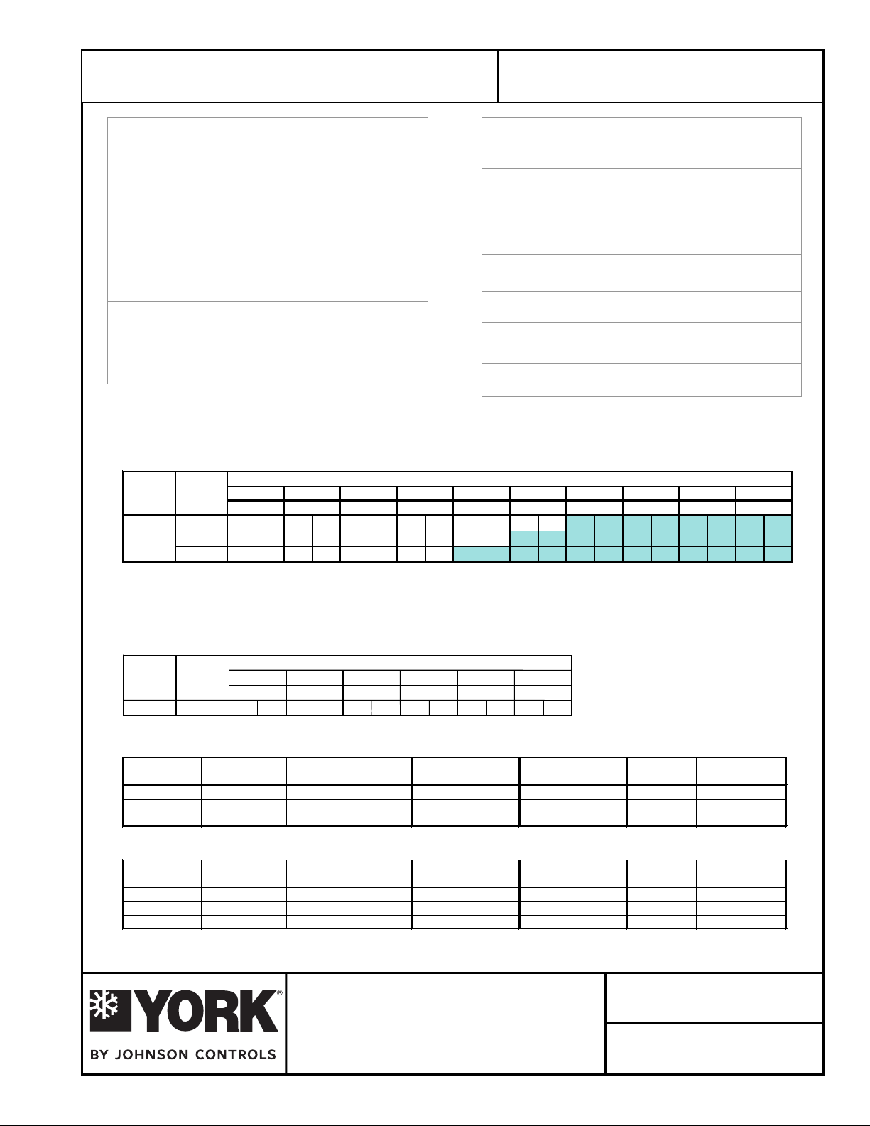
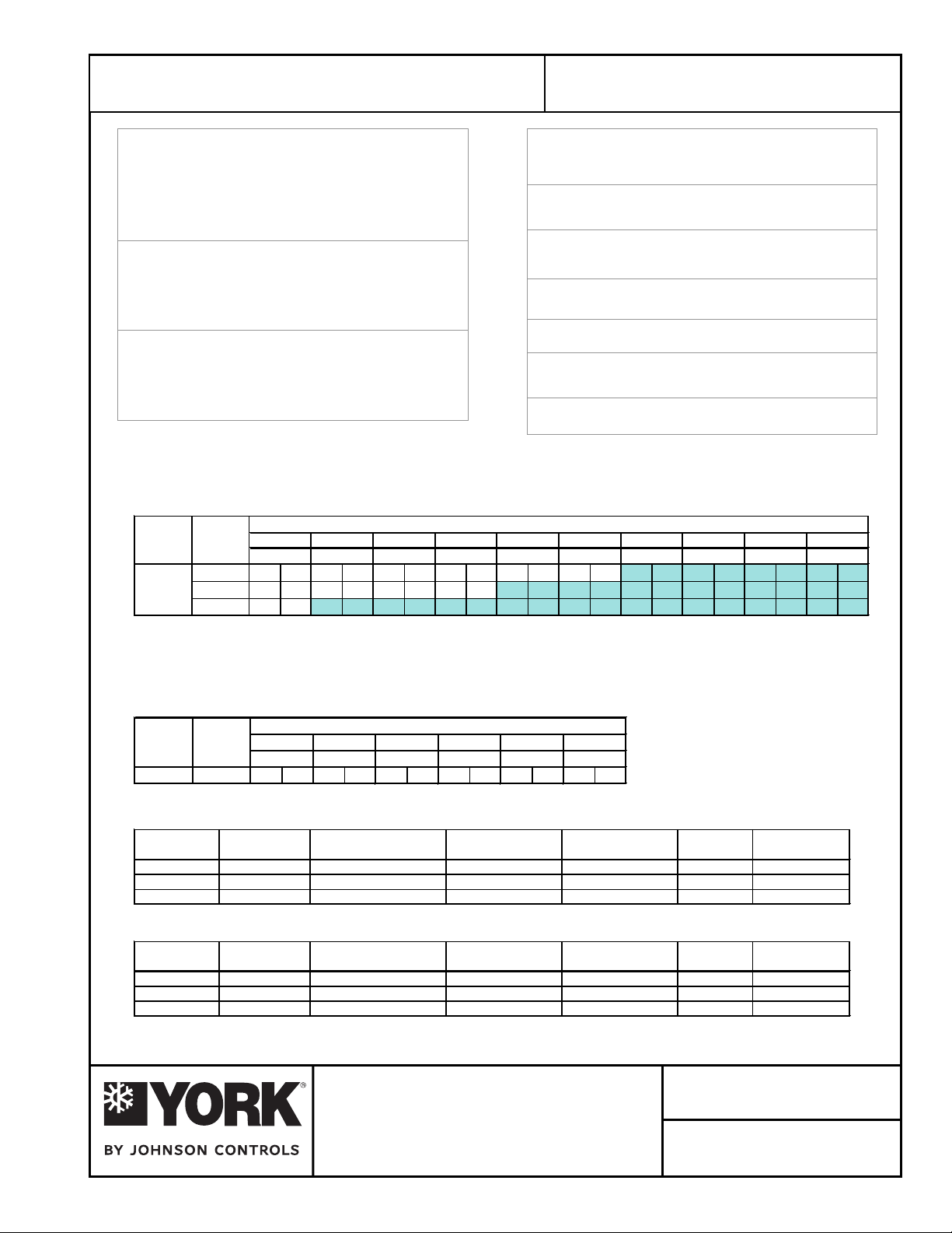
Gross Cooling Capacity [Btuh]: 95,000*
Design CFM: 3,200
Evaporator Coil Face Area: 8.67 [sq ft]
Rows/FPI : 3/10
Refrigerant Control: TX Valve
Energy Efficiency Ratio: 11.55 EER**
Net Cooling Capacity [Btuh]: 92,000**
Net Cooling CFM: 3,200
Evaporator Fan No./Type: 1/CENTRIFUGAL
Diameter x Width [in]: 12x15
Drive: Adjustable Belt
Motor HP : 1.5 / 2.0
[Standard/Oversized]
Condenser Fan No./Type: 2/CENTRIFUGAL
Diameter x Width [in]: 12x11
Drive: tleB elbatsujdA
Motor HP : 2.0
[Standard]
*Cooling performance is rated at 95°F ambient, 80°F entering dry bulb, 67°F wet bulb
and CFM listed. Gross capacity does not include the effect of fan motor heat.
**Rated in accordance with ARI Standard 360-2000
Condenser Coil Face Area: 12.28 [sq ft]
Rows/FPI: 4/14
Compressor No./Type: 2/Scroll
Refrigerant Circuits: 2 / Independent
Refrigerant: R22
Charge: 8.75 Lbs./ circuit
Filters - Qty./Size: 4/14x25x2
Operating Weight [lbs.]: 1005
Shipping Weight [lbs.]: 1060
Condensate Connection: 3 / 4 NPT
EVAPORATOR FAN PERFORMANCE
MODEL SUPPLY 0.2 0.4 0.6 0.8 1.0 1.2 1.4 1.6 1.8 2.0
# CFM RPM BHP RPM BHP RPM BHP RPM BHP RPM BHP RPM BHP RPM BHP RPM BHP RPM BHP RPM BHP
3000
734 0.76 809 0.89 881 1.02 950 1.17 1016 1.32 1079 1.47 1139 1.63 1196 1.79 1251 1.97 1303 2.17
3200DPV096
771 0.90 843 1.03 911 1.17 977 1.32 1040 1.47 1101 1.63 1159 1.81 1214 2.01 ----
811 1.06 879 1.20 944 1.35 1007 1.50 1068 1.66 1128 1.83 1187 2.01
3400
EXTERNAL STATIC PRESSURE - Inches W.C.
- - ----
NOTE:
1. At high evaporator air flows, and wet bulb conditions, condensate carry-over may occur. Adjust airflow downward as necessary.
2. Values include pressure drop from wet coil and clean filters.
3. Shaded areas indicate oversize motors.
CONDENSER FAN PERFORMANCE
EXTERNAL STATIC PRESSURE - Inches W.C.
MODEL OUTDOOR 0.2 0.4 0.6 0.8 1.0 1.2
# CFM RPM BHP RPM BHP RPM BHP RPM BHP RPM BHP RPM BHP
DPV096
4700
737 1.19 811 1.38 882 1.59 951 1.82 1017 2.07 - -
ELECTRICAL DATA – STANDARD MOTOR
MODEL
#
DPV096
DPV096
DPV096
VOLTAGE COMPRESSOR EVAPORATOR FAN CONDENSER FAN MIN. CCT. MAX FUSE /
QTY RLA LRA HP FLA HP FLA AMPACITY CCT. BKR. AMP
208-230/3/60 2 @ 13.9 88.0 1.50 4.5 2.00 5.9 41.68 50
460/3/60 2 @ 7.1 44.0 1.50 2.1 2.00 2.8 20.97 25
575/3/60 2 @ 5.4 34.0 1.50 1.7 2.00 2.2 15.94 20
ELECTRICAL DATA – OVERSIZED MOTOR
MODEL
#
DPV096
DPV096
DPV096
Johnson Controls maintains a continuous product improvement policy, therefore specifications are subject to change without notice.
VOLTAGE COMPRESSOR EVAPORATOR FAN CONDENSER FAN MIN. CCT. MAX FUSE /
208-230/3/60 2 @ 13.9 88.0
460/3/60 2 @ 7.1 44.0
575/3/60 2 @ 5.4 34.0
QTY RLA LRA HP FLA HP FLA AMPACITY CCT. BKR. AMP
2.00
5.9 2.00 5.9 43.08 50
2.00 2.8 2.00 2.8 21.67 25
2.00 2.2 2.00 2.2 16.44 20
DESCRIPTION:
Form YK145.12-PA4 (308)
DPV096 VERTICAL UNIT
AIR-COOLED SELF-CONTAINED
March 2008
Page 3

2 of 4
Page 3
"DPV" SERIES VERTICAL INDOOR SYSTEM
GENERAL MECHANICAL SPECIFICATIONS
GENERAL
All models 5-15 tons ship as factory-charged unitized packages. The 20 ton model shall be shipped as
separate evaporator and condensing unit modules (nitrogen holding charge only). All units may be field
split and installed as separate modules to suit on-site requirements. All packages are designed for freestanding mounting on the floor, or on a field fabricated structural steel stand. The 5, 8, and 10 ton models
are shipped with vertical evaporator fan discharge as standard. The 12, 15, and 20 ton models are
shipped horizontal discharge as standard.
CABINET
All cabinets are completely constructed of heavy gauge galvanized steel. The entire unit interior ( both
evaporator and condensing section ) is insulated with 1/2" thick,
are
equipped with lifting handles for ease of removal and handling. Duct flanges for condenser discharge,
condenser intake, and evaporator discharges, are provided with the unit for field installation. Duct flange
on evaporator return is incorporated into the filter frame.
COMPRESSORS
All models utilize "Scroll" type hermetic compressors. Compressors are mounted on rubber isolators to
minimize vibration transmission. Internal overload protection is provided. External high pressure and low
pressure cutout switches are included in each compressor control circuit. Crankcase heaters are
standard on all models.
2 lb. density insulation. Service panels
REFRIGERANT CIRCUITS
The 5 ton units have a single refrigeration circuit. The 8-20 ton units feature two independent refrigeration
circuits. Each refrigeration circuit includes
equali
zer), liquid line filter drier, sight glass/moisture indicator, and service gauge ports.
EVAPORATOR AND CONDENSER COILS
The evaporator and condenser coils are constructed of internally enhanced copper tubes mechanically
bonded to rippled aluminum plate fins. Both coils are employed in a draw-thru configuration. Large
evaporator coil face area minimizes potential water blow-off.
INDOOR/OUTDOOR FANS
Forward curved, double inlet and double width centrifugal blowers are used for both evaporator and
condenser air movement. Blower wheels are fabricated of galvanized steel. Blowers employ solid steel
shafts, supported in permanently lubricated ball bearing. All blowers are belt driven. Variable-pitch motor
sheaves allow for field adjustment
ELECTRI
All units are completely factory wired with all necessary controls. Manual reset protection is provided on
both evaporator and condenser motors. A manual reset circuit is also provided on each compressor
control circuit in the event of high/low pressure cutout. A 24 volt control circuit, with oversize transformer,
is provided for field connection.
FILTERS
All models are shipped with 2-inch thick medium-efficiency throwaway filters factory installed. Filter rack
is external to the cabinet (shipped loose).
CAL/CONTROLS
of blower rpm.
an adjustable thermal expansion valve (with external
Johnson Controls maintains a continuous product improvement policy, therefore specifications are subject to change without notice.
DESCRIPTION:
Form YK145.12-PA4 (308)
MECHANICAL SPECIFICATIONS
DPV096 VERTICAL UNIT
AIR-COOLED SELF-CONTAINED
DATE:
March 2008
Page 4
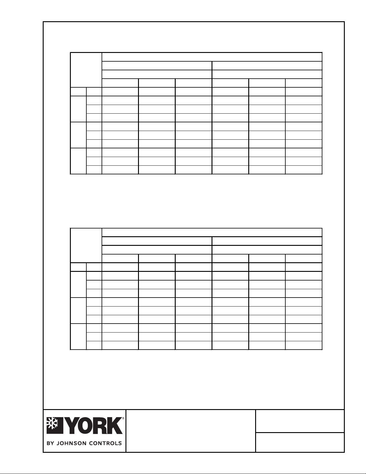
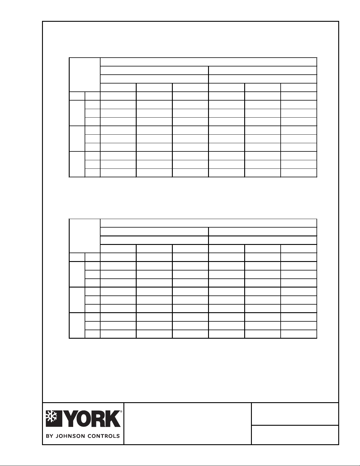
8 TON
Page 4
CFM EDB
75°F
3000 80°F
85°F
75°F
3200 80°F
85°F
75°F
3400 80°F
85°F
3 of 4
Ambient Condenser Air Temperature
F°59F°58
BWEBWE
62°F 67°F 72°F 62°F 67°F 72°F
TC SC TC SC TC SC TC SC TC SC TC SC
90.0 72.0 97.5 57.3 106.7 43.8 86.8 70.6 94.1 55.9 102.5 42.2
91.3 86.7 98.2 71.6 107.6 57.8 88.4 85.8 94.7 70.2 103.4 56.2
96.6 96.6 99.1 86.8 108.2 72.4 93.7 93.7 95.6 85.2 103.7 70.9
91.1 74.1 98.3 58.5 107.1 44.1 87.7 72.6 94.8 57.0 102.8 42.5
92.7 90.0 99.0 73.5 108.2 58.8 89.1 87.8 95.5 72.1 103.6 57.3
98.3 98.3 100.1 89.4 108.6 74.3 95.3 95.3 96.5 87.9 104.0 72.7
91.8 76.0 99.0 59.6 107.5 44.4 88.2 74.5 95.4 58.2 103.0 42.7
93.4 92.0 99.7 75.4 108.4 59.8 92.3 92.3 96.1 74.0 103.8 58.2
99.8 99.8 100.9 92.0 108.8 76.0 96.8 96.8 97.2 90.4 104.1 74.5
8 TON
CFM EDB
75°F
3000 80°F
85°F
75°F
3200 80°F
85°F
75°F
3400 80°F
85°F
Ambient Condenser Air Temperature
F°511F°501
BWEBWE
62°F 67°F 72°F 62°F 67°F 72°F
TC SC TC SC TC SC TC SC TC SC TC SC
83.3 69.1 90.3 54.3 97.9 40.5 79.4 67.4 86.2 52.7 92.7 38.5
84.6 83.4 90.9 68.7 98.6 54.5 82.6 82.6 86.7 67.0 93.4 52.6
90.7 90.7 91.8 83.6 98.9 69.1 87.3 87.3 87.7 81.8 93.5 67.3
83.9 71.0 91.0 55.5 98.0 40.8 79.7 69.2 86.7 53.8 92.7 38.8
87.5 87.5 91.5 70.6 98.7 55.5 84.0 84.0 87.2 69.0 93.3 53.6
92.1 92.1 92.5 86.2 99.1 71.0 88.7 88.7 88.1 84.3 93.5 69.1
84.3 72.9 91.5 56.6 98.2 41.0 81.4 72.1 87.2 54.9 92.7 39.0
88.9 88.9 92.2 92.2 98.7 56.4 85.2 85.2 87.6 70.8 93.1 54.5
93.5 93.5 93.0 88.6 99.0 72.7 89.9 89.9 90.3 87.8 93.2 62.6
DESCRIPTION:
COOLING PERFORMANCE DATA
DPV096 VERTICAL UNIT
AIR-COOLED SELF-CONTAINED
Form YK145.12-PA4 (308)
DATE:
March 2008
Page 5
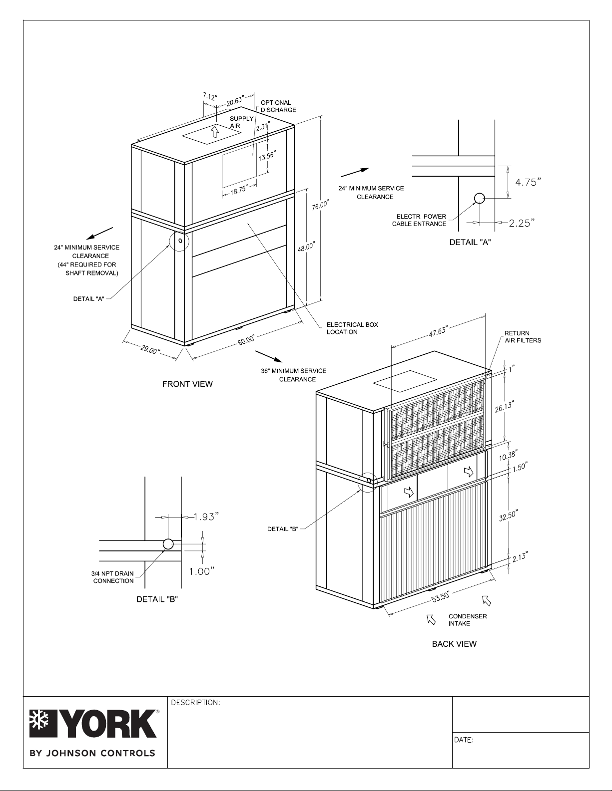
DPV096 AND DPV120 DIMENSIONAL DATA
Page 5
4 of 4
DIMENSIONAL DATA
DPV096 & DPV120 VERTICAL UNIT
AIR-COOLED SELF-CONTAINED
Form YK145.12-PA4 (308)
March 2008
Page 6
PROJECT: TAG:
Page 6
1 of 4
Gross Cooling Capacity [Btuh]: 122,000*
Design CFM: 4,000
Evaporator Coil Face Area: 8.67 [sq ft]
Rows/FPI : 4/10
Refrigerant Control: TX Valve
Energy Efficiency Ratio: 10.60 EER**
Net Cooling Capacity [Btuh]: 117,000**
Net Cooling CFM: 3,600
Evaporator Fan No./Type: 1/CENTRIFUGAL
Diameter x Width [in]: 12x15
Drive: Adjustable Belt
Motor HP : 2.0 / 3.0
[Standard/Oversized]
Condenser Fan No./Type: 2/CENTRIFUGAL
Diameter x Width [in]: 12x11
Drive: tleB elbatsujdA
Motor HP : 3.0
[Standard]
*Cooling performance is rated at 95°F ambient, 80°F entering dry bulb, 67°F wet bulb
and CFM listed. Gross capacity does not include the effect of fan motor heat.
**Rated in accordance with ARI Standard 360-2000
Condenser Coil Face Area: 12.28 [sq ft]
Rows/FPI: 4/14
Compressor No./Type: 2/Scroll
Refrigerant Circuits: 2 / Independent
Refrigerant: R22
Charge: 9.5 Lbs./ circuit
Filters - Qty./Size: 4/14x25x2
Operating Weight [lbs.]: 1065
Shipping Weight [lbs.]: 1110
Condensate Connection: 3 / 4 NPT
EVAPORATOR FAN PERFORMANCE
MODEL SUPPLY 0.2 0.4 0.6 0.8 1.0 1.2 1.4 1.6 1.8 2.0
# CFM RPM BHP RPM BHP RPM BHP RPM BHP RPM BHP RPM BHP RPM BHP RPM BHP RPM BHP RPM BHP
3600
DPV120
800 1.13 867 1.28 931 1.43 993 1.59 1052 1.74 1100 1.88 1158 2.11 1225 2.25 1245 2.50 1335 2.66
4000
876 1.52 937 1.68 996 1.85 1052 2.01 1100 2.23 1154 2.31 1200 2.55 1263 2.72 1304 2.93 1367 3.12
951 1.98 1007 2.16 1062 2.35 1120 2.52 1178 2.76 1204 2.92 1263 3.15
4400
EXTERNAL STATIC PRESSURE - Inches W.C.
------
NOTE:
1. At high evaporator air flows, and wet bulb conditions, condensate carry-over may occur. Adjust airflow downward as necessary.
2. Values include pressure drop from wet coil and clean filters.
3. Shaded areas indicate oversize motors.
CONDENSER FAN PERFORMANCE
EXTERNAL STATIC PRESSURE - Inches W.C.
MODEL OUTDOOR 0.2 0.4 0.6 0.8 1.0 1.2
# CFM RPM BHP RPM BHP RPM BHP RPM BHP RPM BHP RPM BHP
DPV120
5500
804 1.71 873 1.94 941 2.19 1008 2.46 1073 2.75 1136 3.06
ELECTRICAL DATA – STANDARD MOTOR
MODEL
#
DPV120
DPV120
DPV120
VOLTAGE COMPRESSOR EVAPORATOR FAN CONDENSER FAN MIN. CCT. MAX FUSE /
QTY RLA LRA HP FLA HP FLA AMPACITY CCT. BKR. AMP
208-230/3/60 2 @ 19.3 123.0 2.00 5.9 3.00 8.7 58.03 70
460/3/60 2 @ 7.5 49.5 2.00 2.8 3.00 4.0 23.68 30
575/3/60 2 @ 6.4 40.0 2.00 2.2 3.00 3.2 19.80 25
ELECTRICAL DATA – OVERSIZED MOTOR
MODEL
#
DPV120
DPV120
DPV120
Johnson Controls maintains a continuous product improvement policy, therefore specifications are subject to change without notice.
VOLTAGE COMPRESSOR EVAPORATOR FAN CONDENSER FAN M IN. CCT. MAX FUSE /
208-230/3/60 2 @ 19.3 123.0 3.00 8.7 3.00 8.7 60.83 80
460/3/60 2 @ 7.5 49.5
575/3/60 2 @ 6.4 40.0
QTY RLA LRA HP FLA HP FLA AMPACITY CCT. BKR. AMP
3.00
3.00
4.0 3.00 4.0 24.88 30
3.2 3.00 3.2 20.80 25
DESCRIPTION:
Form YK145.12-PA5 (308)
DPV120 VERTICAL UNIT
AIR-COOLED SELF-CONTAINED
March 2008
Page 7
2 of 4
Page 7
"DPV" SERIES VERTICAL INDOOR SYSTEM
GENERAL MECHANICAL SPECIFICATIONS
GENERAL
All models 5-15 tons ship as factory-charged unitized packages. The 20 ton model shall be shipped as
separate evaporator and condensing unit modules (nitrogen holding charge only). All units may be field
split and installed as separate modules to suit on-site requirements. All packages are designed for freestanding mounting on the floor, or on a field fabricated structural steel stand. The 5, 8, and 10 ton models
are shipped with vertical evaporator fan discharge as standard. The 12, 15, and 20 ton models are
shipped horizontal discharge as standard.
CABINET
All cabinets are completely constructed of heavy gauge galvanized steel. The entire unit interior ( both
evaporator and condensing section ) is insulated with 1/2" thick, 2
are
equipped with lifting handles for ease of removal and handling. Duct flanges for condenser discharge,
condenser intake, and evaporator discharges, are provided with the unit for field installation. Duct flange
on evaporator return is incorporated into the filter frame.
COMPRESSORS
All models utilize "Scroll" type hermetic compressors. Compressors are mounted on rubber isolators to
minimize vibration transmission. Internal overload protection is provided. External high pressure and low
pressure cutout switches are included in each compressor control circuit. Crankcase heaters are
standard on all models.
lb. density insulation. Service panels
REFRIGERANT CIRCUITS
The 5 ton units have a single refrigeration circuit. The 8-20 ton units feature two independent refrigeration
circuits. Each refrigeration circuit includes
equali
zer), liquid line filter drier, sight glass/moisture indicator, and service gauge ports.
EVAPORATOR AND CONDENSER COILS
The evaporator and condenser coils are constructed of internally enhanced copper tubes mechanically
bonded to rippled aluminum plate fins. Both coils are employed in a draw-thru configuration. Large
evaporator coil face area minimizes potential water blow-off.
INDOOR/OUTDOOR FANS
Forward curved, double inlet and double width centrifugal blowers are used for both evaporator and
condenser air movement. Blower wheels are fabricated of galvanized steel. Blowers employ solid steel
shafts, supported in permanently lubricated ball bearing. All blowers are belt driven. Variable-pitch motor
sheaves allow for field adjustment
ELECTRI
All units are completely factory wired with all necessary controls. Manual reset protection is provided on
both evaporator and condenser motors. A manual reset circuit is also provided on each compressor
control circuit in the event of high/low pressure cutout. A 24 volt control circuit, with oversize transformer,
is provided for field connection.
FILTERS
All models are shipped with 2-inch thick medium-efficiency throwaway filters factory installed. Filter rack
is external to the cabinet (shipped loose).
CAL/CONTROLS
of blower rpm.
an adjustable thermal expansion valve (with external
Johnson Controls maintains a continuous product improvement policy, therefore specifications are subject to change without notice.
DESCRIPTION:
MECHANICAL SPECIFICATIONS
DPV120 VERTICAL UNIT
AIR-COOLED SELF-CONTAINED
Form YK145.12-PA5 (308)
DATE:
March 2008
Page 8
10 TON
Page 8
CFM EDB
75°F
3600 80°F
85°F
75°F
4000 80°F
85°F
75°F
4400 80°F
85°F
3 of 4
Ambient Condenser Air Temperature
F°59F°58
BWEBWE
62°F 67°F 72°F 62°F 67°F 72°F
TC SC TC SC TC SC TC SC TC SC TC SC
115.4 91.5 124.8 73.0 134.5 53.8 111.0 89.6 120.2 71.1 129.8 52.2
116.6 109.7 125.8 90.9 136.1 72.4 112.6 107.8 120.9 89.0 131.3 70.6
122.5 122.5 126.8 109.4 136.8 90.2 118.8 118.8 121.9 107.4 131.8 88.4
117.2 95.9 126.7 75.7 136.5 56.3 112.5 93.8 121.6 73.6 131.7 54.4
118.8 115.5 127.4 95.2 138.2 75.1 114.7 113.4 122.5 93.2 133.2 73.3
126.2 126.2 128.6 115.3 138.8 94.5 122.3 122.3 123.4 113.1 133.5 92.6
118.4 100.0 127.9 78.1 138.3 57.3 114.9 98.7 122.9 76.1 133.3 55.5
121.7 121.1 128.8 99.3 140.0 77.6 119.1 119.1 123.5 97.2 134.7 75.7
129.4 129.4 129.9 120.7 140.2 98.6 125.1 125.1 126.4 119.5 134.8 96.7
10 TON
CFM EDB
75°F
3600 80°F
85°F
75°F
4000 80°F
85°F
75°F
4400 80°F
85°F
Ambient Condenser Air Temperature
F°511F°501
BWEBWE
62°F 67°F 72°F 62°F 67°F 72°F
TC SC TC SC TC SC TC SC TC SC TC SC
106.3 87.5 115.2 69.1 124.9 50.5 101.1 85.2 109.9 66.9 119.8 49.6
107.2 105.0 115.9 87.0 126.2 68.7 103.4 103.0 110.5 84.8 121.0 66.8
114.8 114.8 116.8 105.3 126.6 86.5 110.6 110.6 111.4 103.1 121.3 84.6
108.6 92.4 116.5 71.6 126.5 52.5 103.5 90.1 111.0 69.4 121.3 50.6
111.8 111.8 117.2 91.2 128.0 71.4 107.4 107.4 111.6 89.0 122.5 69.5
118.0 118.0 119.5 111.8 128.1 90.7 113.6 113.6 114.4 109.4 122.6 88.8
109.9 96.5 117.4 117.4 128.0 53.5 104.6 94.1 111.7 71.7 122.6 51.6
114.5 114.5 118.1 95.2 129.0 73.9 109.8 109.8 112.2 93.0 123.3 71.9
120.7 120.7 121.4 117.1 129.4 94.8 116.1 116.1 117.5 115.5 123.9 92.8
DESCRIPTION:
COOLING PERFORMANCE DATA
DPV120 VERTICAL UNIT
AIR-COOLED SELF-CONTAINED
Form YK145.12-PA5 (308)
DATE:
March 2008
Page 9

DPV096 AND DPV120 DIMENSIONAL DATA
Page 9
4 of 4
DIMENSIONAL DATA
DPV096 & DPV120 VERTICAL UNIT
AIR-COOLED SELF-CONTAINED
Form YK145.12-PA5 (308)
March 2008
Page 10

PROJECT: TAG:
Page 10
1 of 4
Gross Cooling Capacity [Btuh]: 150,000*
Design CFM: 4,800
Evaporator Coil Face Area: 13.03 [sq ft]
Rows/FPI : 3/10
Refrigerant Control: TX Valve
Energy Efficiency Ratio: 10.65 EER**
Net Cooling Capacity [Btuh]: 144,000**
Net Cooling CFM: 4,800
Evaporator Fan No./Type: 2/CENTRIFUGAL
Diameter x Width [in]: 12x9
Drive: Adjustable Belt
Motor HP : 2.0 / 3.0
[Standard/Oversized]
Condenser Fan No./Type: 2/CENTRIFUGAL
Diameter x Width [in]: 15x15
Drive: tleB elbatsujdA
Motor HP : 3.0
[Standard]
*Cooling performance is rated at 95°F ambient, 80°F entering dry bulb, 67°F wet bulb
and CFM listed. Gross capacity does not include the effect of fan motor heat.
**Rated in accordance with ARI Standard 360-2000
Condenser Coil Face Area: 15.82 [sq ft]
Rows/FPI: 4/14
Compressor No./Type: 2/Scroll
Refrigerant Circuits: 2 / Independent
Refrigerant: R22
Charge: 12.13 Lbs./ circuit
Filters - Qty./Size: 2/14x20x2 & 4/14x25x2
Operating Weight [lbs.]: 1335
Shipping Weight [lbs.]: 1395
Condensate Connection: 3 / 4 NPT
EVAPORATOR FAN PERFORMANCE
MODEL SUPPLY 0.2 0.4 0.6 0.8 1.0 1.2 1.4 1.6 1.8 2.0
# CFM RPM BHP RPM BHP RPM BHP RPM BHP RPM BHP RPM BHP RPM BHP RPM BHP RPM BHP RPM BHP
4300
717 1.06 792 1.23 862 1.41 928 1.58 989 1.75 1049 1.93 1100 2.10 1165 2.30 1210 2.50 1245 2.60
4800DPV144
5300
781 1.42 850 1.62 915 1.81 976 2.00 1035 2.20 1091 2.39 1144 2.58 1197 2.79 1245 2.96 - -
848 1.87 912 2.08 972 2.29 1030 2.57 1085 2.72 1138 2.94 1189 3.15
EXTERNAL STATIC PRESSURE - Inches W.C.
- --- - -
NOTE:
1. At high evaporator air flows, and wet bulb conditions, condensate carry-over may occur. Adjust airflow downward as necessary.
2. Values include pressure drop from wet coil and clean filters.
3. Shaded areas indicate oversize motors.
CONDENSER FAN PERFORMANCE
EXTERNAL STATIC PRESSURE - Inches W.C.
MODEL OUTDOOR 0.2 0.4 0.6 0.8 1.0 1.2
# CFM RPM BHP RPM BHP RPM BHP RPM BHP RPM BHP RPM BHP
DPV144
6600
675 1.77 735 2.06 792 2.46 848 2.60 900 3.00 - -
ELECTRICAL DATA – STANDARD MOTOR
MODEL
#
DPV144
DPV144
DPV144
VOLTAGE COMPRESSOR EVAPORATOR FAN CONDENSER FAN MIN. CCT. M AX FUSE /
QTY RLA LRA HP FLA HP FLA AMPACITY CCT. BKR. AMP
208-230/3/60 2 @ 20.7 156.0 2.00 5.9 3.00 8.7 61.18 80
460/3/60 2 @ 10.0 75.0 2.00 2.8 3.00 4.0 29.30 35
575/3/60 2 @ 8.2 54.0 2.00 2.2 3.00 3.2 23.85 30
ELECTRICAL DATA – OVERSIZED MOTOR
MODEL
#
DPV144
DPV144
DPV144
Johnson Controls maintains a continuous product improvement policy, therefore specifications are subject to change without notice.
VOLTAGE COMPRESSOR EVAPORATOR FAN CONDENSER FAN MIN. CCT. M AX FUSE /
208-230/3/60 2 @ 20.7 156.0
460/3/60 2 @ 10.0 75.0
575/3/60 2 @ 8.2 54.0
QTY RLA LRA HP FLA HP FLA AMPACITY CCT. BKR. AMP
DESCRIPTION:
3.00
3.00
3.00
8.7 3.00 8.7 63.98 80
4.0 3.00 4.0 30.50 40
3.2 3.00 3.2 24.85 30
Form YK145.12-PA6 (308)
DPV144 VERTICAL UNIT
AIR-COOLED SELF-CONTAINED
DATE:
March 2008
Page 11

2 of 4
Page 11
"DPV" SERIES VERTICAL INDOOR SYSTEM
GENERAL MECHANICAL SPECIFICATIONS
GENERAL
All models 5-15 tons ship as factory-charged unitized packages. The 20 ton model shall be shipped as
separate evaporator and condensing unit modules (nitrogen holding charge only). All units may be field
split and installed as separate modules to suit on-site requirements. All packages are designed for freestanding mounting on the floor, or on a field fabricated structural steel stand. The 5, 8, and 10 ton models
are shipped with vertical evaporator fan discharge as standard. The 12, 15, and 20 ton models are
shipped horizontal discharge as standard.
CABINET
All cabinets are completely constructed of heavy gauge galvanized steel. The entire unit interior ( both
evaporator and condensing section ) is insulated with 1/2" thick, 2
are
equipped with lifting handles for ease of removal and handling. Duct flanges for condenser discharge,
condenser intake, and evaporator discharges, are provided with the unit for field installation. Duct flange
on evaporator return is incorporated into the filter frame.
COMPRESSORS
All models utilize "Scroll" type hermetic compressors. Compressors are mounted on rubber isolators to
minimize vibration transmission. Internal overload protection is provided. External high pressure and low
pressure cutout switches are included in each compressor control circuit. Crankcase heaters are
standard on all models.
lb. density insulation. Service panels
REFRIGERANT CIRCUITS
The 5 ton units have a single refrigeration circuit. The 8-20 ton units feature two independent refrigeration
circuits. Each refrigeration circuit includes
equali
zer), liquid line filter drier, sight glass/moisture indicator, and service gauge ports.
EVAPORATOR AND CONDENSER COILS
The evaporator and condenser coils are constructed of internally enhanced copper tubes mechanically
bonded to rippled aluminum plate fins. Both coils are employed in a draw-thru configuration. Large
evaporator coil face area minimizes potential water blow-off.
INDOOR/OUTDOOR FANS
Forward curved, double inlet and double width centrifugal blowers are used for both evaporator and
condenser air movement. Blower wheels are fabricated of galvanized steel. Blowers employ solid steel
shafts, supported in permanently lubricated ball bearing. All blowers are belt driven. Variable-pitch motor
sheaves allow for field adjustment
ELECTRI
All units are completely factory wired with all necessary controls. Manual reset protection is provided on
both evaporator and condenser motors. A manual reset circuit is also provided on each compressor
control circuit in the event of high/low pressure cutout. A 24 volt control circuit, with oversize transformer,
is provided for field connection.
FILTERS
All models are shipped with 2-inch thick medium-efficiency throwaway filters factory installed. Filter rack
is external to the cabinet (shipped loose).
CAL/CONTROLS
of blower rpm.
an adjustable thermal expansion valve (with external
Johnson Controls maintains a continuous product improvement policy, therefore specifications are subject to change without notice.
DESCRIPTION:
MECHANICAL SPECIFICATIONS
DPV144 VERTICAL UNIT
AIR-COOLED SELF-CONTAINED
Form YK145.12-PA6 (308)
DATE:
March 2008
Page 12

12 TON
Page 12
CFM EDB
75°F
4300 80°F
85°F
75°F
4800 80°F
85°F
75°F
5300 80°F
85°F
3 of 4
Ambient Condenser Air Temperature
F°59F°58
BWEBWE
62°F 67°F 72°F 62°F 67°F 72°F
TC SC TC SC TC SC TC SC TC SC TC SC
140.0 108.7 151.6 87.4 167.1 66.6 135.4 106.7 146.6 85.3 160.8 64.5
145.8 132.3 152.8 108.0 168.5 88.6 139.8 129.4 147.1 106.0 162.2 86.2
148.1 148.1 153.1 128.8 169.4 109.7 143.9 143.9 147.7 126.6 163.0 107.3
143.1 114.2 154.1 90.5 168.7 69.2 138.1 112.0 148.9 88.4 162.3 66.8
144.8 137.4 155.0 113.0 170.4 91.5 138.6 134.4 150.0 111.0 163.7 89.0
152.8 152.8 156.8 137.3 171.2 114.5 148.4 148.4 151.5 134.9 164.3 112.1
145.1 119.0 156.2 93.4 170.0 70.1 139.7 116.7 150.6 91.2 163.3 67.7
147.8 144.5 157.3 117.9 171.4 94.0 142.5 141.4 151.6 115.7 164.4 91.5
156.8 156.8 159.0 143.7 172.1 119.1 152.2 152.2 153.4 141.2 164.9 116.6
12 TON
CFM EDB
75°F
4300 80°F
85°F
75°F
4800 80°F
85°F
75°F
5300 80°F
85°F
Ambient Condenser Air Temperature
F°511F°501
BWEBWE
62°F 67°F 72°F 62°F 67°F 72°F
TC SC TC SC TC SC TC SC TC SC TC SC
130.2 104.3 141.1 83.0 153.9 63.2 124.4 101.8 134.7 80.4 146.1 60.3
133.3 126.2 142.1 103.7 155.2 83.5 127.4 123.9 135.6 101.1 147.2 80.6
139.4 139.4 143.2 125.6 155.8 104.8 134.3 134.3 136.8 122.8 147.6 101.8
132.4 109.5 143.1 86.0 154.9 64.1 125.9 106.7 136.3 83.3 146.7 61.0
134.4 132.3 144.0 108.7 156.1 86.2 130.9 130.9 137.2 106.0 147.7 83.2
143.6 143.6 145.5 132.3 156.7 109.4 138.1 138.1 138.7 129.4 147.9 106.4
133.7 114.1 144.5 88.8 155.4 64.8 126.8 111.3 137.6 86.1 146.8 61.6
140.1 140.1 145.5 113.4 156.6 88.7 134.1 134.1 138.4 110.7 147.6 85.6
147.0 147.0 146.9 138.5 157.0 113.9 141.2 141.2 142.1 137.2 147.8 110.8
DESCRIPTION:
COOLING PERFORMANCE DATA
DPV144 VERTICAL UNIT
AIR-COOLED SELF-CONTAINED
Form YK145.12-PA6 (308)
DATE:
March 2008
Page 13

DPV0144 AND DPV180 DIMENSIONAL DATA
Page 13
4 of 4
DPV144
DPV180
DIMENSIONAL DATA
DPV144 & DPV180 VERTICAL UNIT
AIR-COOLED SELF-CONTAINED
Form YK145.12-PA6 (308)
March 2008
Page 14

PROJECT: TAG:
Page 14
1 of 4
Gross Cooling Capacity [Btuh]: 186,000*
Design CFM: 6,000
Evaporator Coil Face Area: 13.03 [sq ft]
Rows/FPI : 4/10
Refrigerant Control: TX Valve
Energy Efficiency Ratio: 9.80 EER**
Net Cooling Capacity [Btuh]: 178,000**
Net Cooling CFM: 5,500
Evaporator Fan No./Type: 2/CENTRIFUGAL
Diameter x Width [in]: 15x9
Drive: Adjustable Belt
Motor HP : 5.0 / NA
[Standard/Oversized]
Condenser Fan No./Type: 2/CENTRIFUGAL
Diameter x Width [in]: 15x15
Drive: tleB elbatsujdA
Motor HP : 5.0
[Standard]
*Cooling performance is rated at 95°F ambient, 80°F entering dry bulb, 67°F wet bulb
and CFM listed. Gross capacity does not include the effect of fan motor heat.
**Rated in accordance with ARI Standard 360-2000
Condenser Coil Face Area: 15.82 [sq ft]
Rows/FPI: 4/14
Compressor No./Type: 2/Scroll
Refrigerant Circuits: 2 / Independent
Refrigerant: R22
Charge: 13.83 Lbs./ circuit
Filters - Qty./Size: 2/14x20x2 & 4/14x25x2
Operating Weight [lbs.]: 1465
Shipping Weight [lbs.]: 1525
Condensate Connection: 3 / 4 NPT
EVAPORATOR FAN PERFORMANCE
MODEL SUPPLY 0.2 0.4 0.6 0.8 1.0 1.2 1.4 1.6 1.8 2.0
# CFM RPM BHP RPM BHP RPM BHP RPM BHP RPM BHP RPM BHP RPM BHP RPM BHP RPM BHP RPM BHP
5400
765 1.93 818 2.16 870 2.41 920 2.70 970 2.90 1010 3.20 1050 3.46 1100 3.70 1145 3.90 1180 4.30
6000DPV180
824 2.52 873 2.77 920 3.03 967 3.30 1010 3.58 1052 3.90 1097 4.24 1137 4.59 1178 4.95 1220 5.33
903 3.33 947 3.60 991 3.89 1034 4.19 1076 4.49 1110 4.80 1150 5.10
6600
EXTERNAL STATIC PRESSURE - Inches W.C.
- -----
NOTE:
1. At high evaporator air flows, and wet bulb conditions, condensate carry-over may occur. Adjust airflow downward as necessary.
2. Values include pressure drop from wet coil and clean filters.
3. Shaded areas indicate oversize motors.
CONDENSER FAN PERFORMANCE
EXTERNAL STATIC PRESSURE - Inches W.C.
MODEL OUTDOOR 0.2 0.4 0.6 0.8 1.0 1.2
# CFM RPM BHP RPM BHP RPM BHP RPM BHP RPM BHP RPM BHP
DPV180
7500
725 2.35 780 2.67 834 3.01 886 3.37 936 3.76 983 4.18
ELECTRICAL DATA – STANDARD MOTOR
MODEL
#
DPV180
DPV180
DPV180
Johnson Controls maintains a continuous product improvement policy, therefore specifications are subject to change without notice.
VOLTAGE COMPRESSOR EVAPORATOR FAN CONDENSER FAN MIN. CCT. MAX FUSE /
QTY RLA LRA HP FLA HP FLA AMPACITY CCT. BKR. AMP
208-230/3/60 2 @ 28.6 196.0 5.00 13.7 5.00 13.7 91.75 110
460/3/60 2 @ 14.2 100.0 5.00 6.6 5.00 6.6 45.15 50
575/3/60 2 @ 9.7 90.0 5.00 5.3 5.00 5.3 32.43 40
DESCRIPTION:
Form YK145.12-PA7 (308)
DPV180 VERTICAL UNIT
AIR-COOLED SELF-CONTAINED
DATE:
March 2008
Page 15

2 of 4
Page 15
"DPV" SERIES VERTICAL INDOOR SYSTEM
GENERAL MECHANICAL SPECIFICATIONS
GENERAL
All models 5-15 tons ship as factory-charged unitized packages. The 20 ton model shall be shipped as
separate evaporator and condensing unit modules (nitrogen holding charge only). All units may be field
split and installed as separate modules to suit on-site requirements. All packages are designed for freestanding mounting on the floor, or on a field fabricated structural steel stand. The 5, 8, and 10 ton models
are shipped with vertical evaporator fan discharge as standard. The 12, 15, and 20 ton models are
shipped horizontal discharge as standard.
CABINET
All cabinets are completely constructed of heavy gauge galvanized steel. The entire unit interior ( both
evaporator and condensing section ) is insulated with 1/2" thick, 2
are
equipped with lifting handles for ease of removal and handling. Duct flanges for condenser discharge,
condenser intake, and evaporator discharges, are provided with the unit for field installation. Duct flange
on evaporator return is incorporated into the filter frame.
COMPRESSORS
All models utilize "Scroll" type hermetic compressors. Compressors are mounted on rubber isolators to
minimize vibration transmission. Internal overload protection is provided. External high pressure and low
pressure cutout switches are included in each compressor control circuit. Crankcase heaters are
standard on all models.
lb. density insulation. Service panels
REFRIGERANT CIRCUITS
The 5 ton units have a single refrigeration circuit. The 8-20 ton units feature two independent refrigeration
circuits. Each refrigeration circuit includes
equali
zer), liquid line filter drier, sight glass/moisture indicator, and service gauge ports.
EVAPORATOR AND CONDENSER COILS
The evaporator and condenser coils are constructed of internally enhanced copper tubes mechanically
bonded to rippled aluminum plate fins. Both coils are employed in a draw-thru configuration. Large
evaporator coil face area minimizes potential water blow-off.
INDOOR/OUTDOOR FANS
Forward curved, double inlet and double width centrifugal blowers are used for both evaporator and
condenser air movement. Blower wheels are fabricated of galvanized steel. Blowers employ solid steel
shafts, supported in permanently lubricated ball bearing. All blowers are belt driven. Variable-pitch motor
sheaves allow for field adjustment
ELECTRI
All units are completely factory wired with all necessary controls. Manual reset protection is provided on
both evaporator and condenser motors. A manual reset circuit is also provided on each compressor
control circuit in the event of high/low pressure cutout. A 24 volt control circuit, with oversize transformer,
is provided for field connection.
FILTERS
All models are shipped with 2-inch thick medium-efficiency throwaway filters factory installed. Filter rack
is external to the cabinet (shipped loose).
CAL/CONTROLS
of blower rpm.
an adjustable thermal expansion valve (with external
Johnson Controls maintains a continuous product improvement policy, therefore specifications are subject to change without notice.
DESCRIPTION:
MECHANICAL SPECIFICATIONS
DPV180 VERTICAL UNIT
AIR-COOLED SELF-CONTAINED
Form YK145.12-PA7 (308)
DATE:
March 2008
Page 16

15 TON
Page 16
CFM EDB
75°F
5400 80°F
85°F
75°F
6000 80°F
85°F
75°F
6600 80°F
85°F
3 of 4
Ambient Condenser Air Temperature
F°59F°58
BWEBWE
62°F 67°F 72°F 62°F 67°F 72°F
TC SC TC SC TC SC TC SC TC SC TC SC
175.4 138.5 189.7 110.0 207.4 82.9 168.8 135.5 182.8 107.8 200.6 81.8
177.1 165.8 191.0 137.5 209.1 111.5 171.2 163.1 184.0 134.7 201.4 108.4
185.6 185.6 192.5 165.4 210.0 139.1 180.0 180.0 185.6 162.4 202.6 135.9
178.1 145.0 192.4 114.6 209.1 86.2 171.2 142.0 185.1 111.6 200.0 82.9
180.6 174.7 193.7 144.0 210.6 115.1 174.3 171.8 186.3 141.1 201.5 111.8
191.3 191.3 195.5 174.2 211.2 145.0 185.4 185.4 187.9 171.1 201.9 141.8
180.0 151.2 194.5 118.3 209.9 87.1 174.8 149.4 186.9 115.3 200.7 83.8
184.9 183.4 195.8 150.2 211.3 118.3 180.4 180.4 188.2 147.2 201.6 114.8
196.1 196.1 197.6 182.5 211.9 150.9 189.9 189.9 192.2 180.6 202.0 147.5
15 TON
CFM EDB
75°F
5400 80°F
85°F
75°F
6000 80°F
85°F
75°F
6600 80°F
85°F
Ambient Condenser Air Temperature
F°511F°501
BWEBWE
62°F 67°F 72°F 62°F 67°F 72°F
TC SC TC SC TC SC TC SC TC SC TC SC
161.6 132.3 175.0 104.6 189.4 78.3 153.0 128.5 166.3 101.0 178.7 74.3
162.9 158.9 176.1 131.5 190.9 104.8 156.5 155.5 167.3 128.0 180.0 100.8
173.9 173.9 177.6 159.0 191.4 132.3 166.9 166.9 168.7 155.4 180.4 128.3
163.3 138.6 177.2 108.4 190.0 79.2 156.7 136.0 167.9 104.7 178.7 75.1
169.0 169.0 178.0 137.8 191.3 108.0 162.1 162.1 168.7 134.3 179.8 104.0
178.9 178.9 181.5 168.9 191.6 138.2 171.5 171.5 173.1 164.9 180.0 134.2
167.0 145.9 178.7 112.0 190.2 80.0 158.3 141.9 169.0 108.2 178.6 75.8
173.6 173.6 179.6 143.9 191.0 111.1 165.8 165.8 170.0 140.3 178.8 106.9
183.0 183.0 184.5 177.0 191.2 143.8 175.4 175.4 177.6 174.3 178.9 139.7
DESCRIPTION:
COOLING PERFORMANCE DATA
DPV180 VERTICAL UNIT
AIR-COOLED SELF-CONTAINED
Form YK145.12-PA7 (308)
DATE:
March 2008
Page 17

DPV144 AND DPV180 DIMENSIONAL DATA
Page 17
4 of 4
DPV144
DPV180
DIMENSIONAL DATA
DPV144 & DPV180 VERTICAL UNIT
AIR-COOLED SELF-CONTAINED
Form YK145.12-PA7 (308)
March 2008
Page 18

PROJECT: TAG:
Page 18
1 of 4
Gross Cooling Capacity [Btuh]: 244,000*
Design CFM: 8,000
Evaporator Coil Face Area: 19.00 [sq ft]
Rows/FPI : 4/10
Refrigerant Control: TX Valve
Energy Efficiency Ratio: 10.10 EER**
Net Cooling Capacity [Btuh]: 236,000**
Net Cooling CFM: 6,800
Evaporator Fan No./Type: 2/CENTRIFUGAL
Diameter x Width [in]: 15x15
Drive: Adjustable Belt
Motor HP : 5.0 / 7.5
[Standard/Oversized]
Condenser Fan No./Type: 2/CENTRIFUGAL
Diameter x Width [in]: 18x13
Drive: tleB elbatsujdA
Motor HP : 7.5
[Standard]
*Cooling performance is rated at 95°F ambient, 80°F entering dry bulb, 67°F wet bulb
and CFM listed. Gross capacity does not include the effect of fan motor heat.
**Rated in accordance with ARI Standard 360-2000
Condenser Coil Face Area: 20.55 [sq ft]
Rows/FPI: 4/14
Compressor No./Type: 2/Scroll
Refrigerant Circuits: 2 / Independent
Refrigerant: R22
Charge: 18.35 Lbs./ circuit
Filters - Qty./Size: 6/20x25x2
Operating Weight [lbs.]: 1720
Shipping Weight [lbs.]: 1805
Condensate Connection: 3 / 4 NPT
EVAPORATOR FAN PERFORMANCE
MODEL SUPPLY 0.2 0.4 0.6 0.8 1.0 1.2 1.4 1.6 1.8 2.0
# CFM RPM BHP RPM BHP RPM BHP RPM BHP RPM BHP RPM BHP RPM BHP RPM BHP RPM BHP RPM BHP
7200
657 1.89 717 2.19 774 2.51 829 2.84 875 3.18 933 3.53 972 3.89 1024 4.26 1072 4.63 1113 5.02
8000DPV240
717 2.51 772 2.84 825 3.20 875 3.55 924 3.92 976 4.31 1022 4.72 1062 5.15 1105 5.60 1145 6.07
778 3.27 830 3.64 878 4.01 925 4.40 970 4.79 1015 5.20 1067 5.63 1102 6.08 1140 6.54 1183 7.03
8800
EXTERNAL STATIC PRESSURE - Inches W.C.
NOTE:
1. At high evaporator air flows, and wet bulb conditions, condensate carry-over may occur. Adjust airflow downward as necessary.
2. Values include pressure drop from wet coil and clean filters.
3. Shaded areas indicate oversize motors.
CONDENSER FAN PERFORMANCE
EXTERNAL STATIC PRESSURE - Inches W.C.
MODEL OUTDOOR 0.2 0.4 0.6 0.8 1.0 1.2
# CFM RPM BHP RPM BHP RPM BHP RPM BHP RPM BHP RPM BHP
DPV240
10200
656 3.72 700 4.12 741 4.50 781 4.91 820 5.32 857 5.73
ELECTRICAL DATA – STANDARD MOTOR
MODEL
#
DPV240
DPV240
DPV240
VOLTAGE COMPRESSOR EVAPORATOR FAN CONDENSER FAN MIN. CCT. MAX FUSE /
QTY RLA LRA HP FLA HP FLA AMPACITY CCT. BKR. AMP
208-230/3/60 2 @ 33.6 225.0 5.00 13.7 7.50 22.2 111.50 125
460/3/60 2 @ 17.3 114.0 5.00 6.6 7.50 10.8 56.33 70
575/3/60 2 @ 13.5 80.0 5.00 5.3 7.50 8.2 43.88 50
ELECTRICAL DATA – OVERSIZED MOTOR
MODEL
#
DPV240
DPV240
DPV240
Johnson Controls maintains a continuous product improvement policy, therefore specifications are subject to change without notice.
VOLTAGE COMPRESSOR EVAPORATOR FAN CONDENSER FAN MIN. CCT. MAX FUSE /
208-230/3/60 2 @ 33.6 225.0
460/3/60 2 @ 17.3 114.0
575/3/60 2 @ 13.5 80.0
QTY RLA LRA HP FLA HP FLA AMPACITY CCT. BKR. AMP
7.50
7.50
7.50
22.2 7.50 22.2 120.00 150
10.8 7.50 10.8 60.53 70
8.4 7.50 8.4 47.18 60
DESCRIPTION:
Form YK145.12-PA8 (308)
DPV240 VERTICAL UNIT
SELF-CONTAINED AIR-COOLED
DATE:
March 2008
Page 19

2 of 4
Page 19
"DPV" SERIES VERTICAL INDOOR SYSTEM
GENERAL MECHANICAL SPECIFICATIONS
GENERAL
All models 5-15 tons ship as factory-charged unitized packages. The 20 ton model shall be shipped as
separate evaporator and condensing unit modules (nitrogen holding charge only). All units may be field
split and installed as separate modules to suit on-site requirements. All packages are designed for freestanding mounting on the floor, or on a field fabricated structural steel stand. The 5, 8, and 10 ton models
are shipped with vertical evaporator fan discharge as standard. The 12, 15, and 20 ton models are
shipped horizontal discharge as standard.
CABINET
All cabinets are completely constructed of heavy gauge galvanized steel. The entire unit interior ( both
evaporator and condensing section ) is insulated with 1/2" thick, 2
are
equipped with lifting handles for ease of removal and handling. Duct flanges for condenser discharge,
condenser intake, and evaporator discharges, are provided with the unit for field installation. Duct flange
on evaporator return is incorporated into the filter frame.
COMPRESSORS
All models utilize "Scroll" type hermetic compressors. Compressors are mounted on rubber isolators to
minimize vibration transmission. Internal overload protection is provided. External high pressure and low
pressure cutout switches are included in each compressor control circuit. Crankcase heaters are
standard on all models.
lb. density insulation. Service panels
REFRIGERANT CIRCUITS
The 5 ton units have a single refrigeration circuit. The 8-20 ton units feature two independent refrigeration
circuits. Each refrigeration circuit includes
equali
zer), liquid line filter drier, sight glass/moisture indicator, and service gauge ports.
EVAPORATOR AND CONDENSER COILS
The evaporator and condenser coils are constructed of internally enhanced copper tubes mechanically
bonded to rippled aluminum plate fins. Both coils are employed in a draw-thru configuration. Large
evaporator coil face area minimizes potential water blow-off.
INDOOR/OUTDOOR FANS
Forward curved, double inlet and double width centrifugal blowers are used for both evaporator and
condenser air movement. Blower wheels are fabricated of galvanized steel. Blowers employ solid steel
shafts, supported in permanently lubricated ball bearing. All blowers are belt driven. Variable-pitch motor
sheaves allow for field adjustment
ELECTRI
All units are completely factory wired with all necessary controls. Manual reset protection is provided on
both evaporator and condenser motors. A manual reset circuit is also provided on each compressor
control circuit in the event of high/low pressure cutout. A 24 volt control circuit, with oversize transformer,
is provided for field connection.
FILTERS
All models are shipped with 2-inch thick medium-efficiency throwaway filters factory installed. Filter rack
is external to the cabinet (shipped loose).
CAL/CONTROLS
of blower rpm.
an adjustable thermal expansion valve (with external
Johnson Controls maintains a continuous product improvement policy, therefore specifications are subject to change without notice.
DESCRIPTION:
MECHANICAL SPECIFICATIONS
DPV240 VERTICAL UNIT
AIR-COOLED SELF-CONTAINED
Form YK145.12-PA8 (308)
DATE:
March 2008
Page 20

20 TON
Page 20
CFM EDB
75°F
7200 80°F
85°F
75°F
8000 80°F
85°F
75°F
8800 80°F
85°F
3 of 4
Ambient Condenser Air Temperature
F°59F°58
BWEBWE
62°F 67°F 72°F 62°F 67°F 72°F
TC SC TC SC TC SC TC SC TC SC TC SC
230.3 184.1 248.7 146.4 269.3 108.2 221.9 180.3 239.8 142.7 258.3 104.3
233.3 221.4 250.2 182.6 270.6 146.3 223.9 216.6 241.0 178.9 259.4 142.1
262.7 262.7 257.8 222.3 278.1 185.8 256.4 256.4 249.3 218.7 266.7 181.7
233.4 193.0 251.7 151.6 270.0 111.9 224.6 189.1 242.4 147.9 258.0 107.4
237.1 233.3 253.1 191.3 271.6 150.9 229.0 228.3 243.4 187.5 259.7 146.6
274.3 274.3 262.9 235.0 279.6 194.2 267.2 267.2 253.9 231.3 267.7 190.0
238.2 203.1 254.1 156.6 269.4 112.7 229.5 199.0 244.2 152.7 256.9 108.2
245.1 245.1 255.4 199.7 271.2 155.0 237.2 237.2 245.4 195.8 258.4 150.5
283.8 283.8 267.3 247.1 279.9 202.1 276.1 276.1 261.2 245.1 267.1 197.7
20 TON
CFM EDB
75°F
7200 80°F
85°F
75°F
8000 80°F
85°F
75°F
8800 80°F
85°F
Ambient Condenser Air Temperature
F°511F°501
BWEBWE
62°F 67°F 72°F 62°F 67°F 72°F
TC SC TC SC TC SC TC SC TC SC TC SC
212.7 176.3 229.6 138.6 245.6 101.9 204.5 173.1 218.5 134.1 231.2 96.6
215.3 212.5 230.8 174.9 246.5 137.4 208.0 208.0 219.3 170.3 231.9 132.1
249.3 249.3 239.8 214.8 253.8 177.1 241.6 241.6 229.1 210.4 239.2 171.9
217.3 186.4 231.7 143.6 244.6 102.6 207.0 181.7 220.0 139.0 229.6 97.1
223.1 223.1 232.9 183.4 246.1 141.7 214.4 214.4 220.6 178.7 230.7 136.4
259.5 259.5 246.4 228.9 254.1 185.3 250.9 250.9 236.3 224.2 238.8 180.0
219.6 194.6 233.2 148.4 242.7 103.0 208.7 189.7 220.1 143.6 226.8 97.3
228.4 228.4 234.1 191.6 244.2 145.5 218.7 218.7 224.8 188.5 227.9 139.9
267.4 267.4 251.9 240.8 252.9 192.9 257.9 257.9 241.6 236.0 236.5 187.5
DESCRIPTION:
COOLING PERFORMANCE DATA
DPV240 VERTICAL UNIT
AIR-COOLED SELF-CONTAINED
Form YK145.12-PA8 (308)
DATE:
March 2008
Page 21

DPV240 DIMENSIONAL DATA
Page 21
4 of 4
DIMENSIONAL DATA
DPV240 VERTICAL UNIT
AIR-COOLED SELF-CONTAINED
Form YK145.12-PA8 (308)
March 2008
Page 22

PROJECT: TAG:
Page 22
1 of 4
Gross Cooling Capacity [Btuh]: 304,000*
Design CFM: 10,000
Evaporator Coil Face Area: 19.797 [sq ft]
Rows/FPI : 4/10
Refrigerant Control: TX Valve
Energy Efficiency Ratio: 9.60 EER**
Net Cooling Capacity [Btuh]: 286,000**
Net Cooling CFM: 8,800
Evaporator Fan No./Type: 2/CENTRIFUGAL
Diameter x Width [in]: 15x15
Drive: Adjustable Belt
Motor HP : 7.5 / 10.0
[Standard/Oversized]
Condenser Fan No./Type: 2/CENTRIFUGAL
Diameter x Width [in]: 18x13
Drive: tleB elbatsujdA
Motor HP : 7.5
[Standard]
*Cooling performance is rated at 95°F ambient, 80°F entering dry bulb, 67°F wet bulb
and CFM listed. Gross capacity does not include the effect of fan motor heat.
**Rated in accordance with ARI Standard 360-2000
Condenser Coil Face Area: 24.13 [sq ft]
Rows/FPI: 4/14
Compressor No./Type: 3/Scroll
Refrigerant Circuits: 3 / Independent
Refrigerant: R22
Charge: 14.65 Lbs./ circuit
Filters - Qty./Size: 8/20x20x2
Operating Weight [lbs.]: 1995
Shipping Weight [lbs.]: 2080
Condensate Connection: 3 / 4 NPT
EVAPORATOR FAN PERFORMANCE
MODEL SUPPLY 0.2 0.4 0.6 0.8 1.0 1.2 1.4 1.6 1.8 2.0
# CFM RPM BHP RPM BHP RPM BHP RPM BHP RPM BHP RPM BHP RPM BHP RPM BHP RPM BHP RPM BHP
9000 785 3.42 836 3.80 884 4.18 930 4.56 975 4.97 1019 5.38 1068 5.81 1100 6.26 1143 6.75 1184 7.24
10000DPV300
11000
861 4.59 907 5.00 952 5.43 994 5.85 1035 6.27 1076 6.73 1116 7.19 1155 7.66 1198 8.15 1225 8.66
938 6.02 981 6.48 1022 6.94 1061 7.39 1100 7.87 1137 8.34 1174 8.82 1210 9.32 1246 9.83 1281 10.34
EXTERNAL STATIC PRESSURE - Inches W.C.
NOTE:
1. At high evaporator air flows, and wet bulb conditions, condensate carry-over may occur. Adjust airflow downward as necessary.
2. Values include pressure drop from wet coil and clean filters.
3. Shaded areas indicate oversize motors.
CONDENSER FAN PERFORMANCE
MODEL OUTDOOR 0.2 0.4 0.6 0.8 1.0 1.2
# CFM RPM BHP RPM BHP RPM BHP RPM BHP RPM BHP RPM BHP
DPV300
11500
687 4.76 728 5.20 767 5.64 805 6.09 841 6.52 876 6.97
EXTERNAL STATIC PRESSURE - Inches W.C.
ELECTRICAL DATA – STANDARD MOTOR
MODEL
#
DPV300
DPV300
DPV300
VOLTAGE COMPRESSOR EVAPORATOR FAN CONDENSER FAN MIN. CCT. MAX FUSE /
QTY RLA LRA HP FLA HP FLA AMPACITY CCT. BKR. AMP
208-230/3/60 3 @ 32.1 195.0 7.50 22.2 7.50 22.2 148.73 175
460/3/60 3 @ 16.4 95.0 7.50 10.8 7.50 10.8 74.90 90
575/3/60 3 @ 12.0 80.0 7.50 8.2 7.50 8.2 55.40 60
ELECTRICAL DATA – OVERSIZED MOTOR
MODEL
#
DPV300
DPV300
DPV300
Johnson Controls maintains a continuous product improvement policy, therefore specifications are subject to change without notice.
VOLTAGE COMPRESSOR EVAPORATOR FAN CONDENSER FAN MIN. CCT. MAX FUSE /
208-230/3/60 3 @ 32.1 195.0 10.00 25.6 7.50 22.2 152.13 175
460/3/60 3 @ 16.4 95.0
575/3/60 3 @ 12.0 80.0
QTY RLA LRA HP FLA HP FLA AMPACITY CCT. BKR. AMP
10.00
10.00
11.6 7.50 10.8 75.70 90
9.6 7.50 8.2 56.80 60
DESCRIPTION:
Form YK145.12-PA9 (308)
DPV300 VERTICAL UNIT
AIR-COOLED SELF-CONTAINED
DATE:
March 2008
Page 23

2 of 4
Page 23
"DPV" SERIES VER
TICAL INDOOR SYSTEM
GENERAL MECHANICAL SPECIFICATIONS
GENERAL
All models 5-15 tons ship as factory-charged unitized packages. The 20 ton model shall be shipped as
separate evaporator and condensing unit modules (nitrogen holding charge only). All units may be field
split and installed as separate modules to suit on-site requirements. All packages are designed for freestanding mounting on the floor, or on a field fabricated structural steel stand. The 5, 8, and 10 ton models
are shipped with vertical evaporator fan discharge as standard. The 12, 15, and 20 ton models are
shipped horizontal discharge as standard.
CABINET
All cabinets are completely
evaporator
are equipped with lifting handles for ease of removal and handling. Duct flanges for condenser discharge,
condenser intake, and evaporator discharges, are provided with the unit for field installation. Duct flange
on evaporator return is incorporated into the filter frame.
COMPRESSORS
All models utilize "Scroll" type hermetic compressors. Compressors are mounted on rubber isolators to
minimize vibration transmission. Internal overload protection is provided. External high pressure and low
pressure cutout switches are included in each compressor control circuit. Crankcase heaters are
standard on all models.
REFRIGERANT CIRCUITS
The 5 ton units
circuits.
equalizer), liquid line filter drier, sight glass/moisture indicator, and service gauge ports.
and condensing section ) is insulated with 1/2" thick, 2 lb. density insulation. Service panels
have a single refrigeration circuit. The 8-20 ton units feature two independent refrigeration
Each refrigeration circuit includes an adjustable thermal expansion valve (with external
constructed of heavy gauge galvanized steel. The entire unit interior ( both
EVAPORATOR AND CONDENSER COILS
The evaporator and condenser coils are constructed of internally enhanced copper tubes mechanically
bonded to rippled aluminum plate fins. Both coils are employed in a draw-thru configuration. Large
evaporator coil face area minimizes potential water blow-off.
INDOOR/OUTDOOR FANS
Forward curved, double inlet and double width centrifugal blowers are used for both evaporator and
condenser air movement. Blower wheels are fabricated of galvanized steel. Blowers employ
shafts,
sheaves allow for field adjustment of blower rpm.
ELECTRICAL/CONTROLS
All units are completely factory wired with all necessary controls. Manual reset protection is provided on
both evaporator and condenser motors. A manual reset circuit is also provided on each compressor
control circuit in the event of high/low pressure cutout. A 24 volt control circuit, with oversize transformer,
is provided for field connection.
FILTERS
All models are shipped with 2-inch thick medium-efficiency throwaway filters factory installed. Filter rack
is external to the cabinet (shipped loose).
supported in permanently lubricated ball bearing. All blowers are belt driven. Variable-pitch motor
Johnson Controls maintains a continuous product improvement policy, therefore specifications are subject to change without notice.
DESCRIPTION:
MECHANICAL SPECIFICATIONS
DPV300 VERTICAL UNIT
AIR-COOLED SELF-CONTAINED
Form YK145.12-PA9 (308)
DATE:
solid steel
March 2008
Page 24

25 TON
Page 24
CFM EDB
75°F
9000 80°F
85°F
75°F
10000 80°F
85°F
75°F
11000 80°F
85°F
3 of 4
Ambient Condenser Air Temperature
F°59F°58
BWEBWE
62°F 67°F 72°F 62°F 67°F 72°F
TC SC TC SC TC SC TC SC TC SC TC SC
285.6 225.4 308.9 180.1 339.4 136.0 275.0 220.8 297.5 175.4 325.1 133.6
291.7 271.6 311.4 224.0 342.3 182.2 281.0 267.2 299.6 219.3 327.5 176.7
304.3 304.3 314.2 269.9 344.0 227.1 294.8 294.8 302.6 265.0 329.0 221.8
290.5 236.1 313.5 186.4 341.9 140.9 279.2 231.3 301.6 181.7 326.7 135.2
297.4 286.2 315.8 234.3 344.8 187.9 286.0 281.3 303.7 229.7 329.2 182.2
313.5 313.5 319.3 284.1 346.0 236.7 303.4 303.4 306.8 279.0 330.2 231.3
291.3 244.8 317.1 192.3 344.4 142.8 279.6 240.0 304.7 187.5 328.3 136.9
301.6 298.9 319.4 244.1 346.7 193.2 296.7 296.7 306.8 239.4 330.6 187.6
321.2 321.2 320.7 296.4 347.7 246.2 310.6 310.6 311.0 293.2 330.9 240.5
25 TON
CFM EDB
75°F
9000 80°F
85°F
75°F
10000 80°F
85°F
75°F
11000 80°F
85°F
Ambient Condenser Air Temperature
F°511F°501
BWEBWE
62°F 67°F 72°F 62°F 67°F 72°F
TC SC TC SC TC SC TC SC TC SC TC SC
263.1 215.6 285.0 170.3 309.2 127.7 249.6 209.8 270.6 164.5 291.5 121.1
266.8 259.8 286.9 214.3 311.3 170.8 255.5 254.0 272.2 208.6 293.1 164.3
284.4 284.4 289.4 259.5 312.6 216.0 272.7 272.7 274.6 253.5 293.9 209.5
266.4 225.8 288.2 176.3 309.8 129.1 255.4 221.7 273.3 170.5 290.9 122.1
273.7 273.5 290.2 224.5 312.1 176.1 266.2 266.2 274.9 218.7 292.6 169.2
292.3 292.3 295.5 275.4 312.8 225.4 279.9 279.9 281.6 268.8 292.9 218.7
270.4 236.7 290.8 182.0 310.6 130.5 256.8 230.6 275.2 176.0 291.2 123.5
284.5 284.5 292.6 234.1 312.5 181.2 270.9 270.9 276.7 228.3 292.2 174.3
298.8 298.8 297.1 286.7 312.6 234.4 285.8 285.8 287.5 283.3 291.4 227.5
DESCRIPTION:
COOLING PERFORMANCE DATA
DPV300 VERTICAL UNIT
AIR-COOLED SELF-CONTAINED
Form YK145.12-PA9 (308)
DATE:
March 2008
Page 25

DPV300 DIMENSIONAL DATA
Page 25
4 of 4
DIMENSIONAL DATA
DPV300 VERTICAL UNIT
AIR-COOLED SELF-CONTAINED
Form YK145.12-PA9 (308)
March 2008
 Loading...