

Page 1
®
CAUTION
THE ENCLOSED INST AL LAT I ON INSTRUCT I ONS AND ANY APPL ICABL E
LOCAL, STATE, AND NATIONAL CODES INCLUDING, BUT NOT LIMI TED
TO, BUILDING, ELECTRICAL, AND MECHANICAL CODES.
THIS PRODUCT MUST B E INSTALLED IN STRICT COMPLIANCE WITH
WARNING
OPERATION OF THE PRODUCT COULD CAUSE PERSONAL INJURY
OR PROPERTY DAM AGE.
I NCORRECT INSTALLATION MAY CREATE A CONDITION WHERE THE
INSTALLATION INSTRUCTION
CHAMPION®SERIES
SINGLE PACKAGE AIR CONDITIONERS
GAS/ELECTRIC, AIR-COOLED
Supersedes: 035-18265-000-A-0801
MODELS D1NA018 THRU 048
AND MODEL D2NA060
1-1/2 THRU 5 TON
(10 SEER)
GENERAL
YORK Model D1NAandD2NAunits are cooling/heating air con
ditioners designed for outdoor installation. Only gas piping, elec
tric power and duct connections are required at the point of
installation.
035-18265-001-A-0202
-
-
WARNING: If the information in this manual is
not followed exactly, a fire or explosion may
result causing property damage, personal
injury or loss of life.
—
Do not store or use gasoline or other
flammable vapors and liquids in the
vicinity of this or any other appliance.
—
WHAT TO DO IF YOU SMELL GAS
·
Do not try to light any appliance.
·
Extinguish any open flames.
·
Do not touch any electrical switch; do
not use any phone in your building.
·
Immediately call your gas supplier from
aneighbor's phone. Follow the gas
supplier's instructions.
·
If you cannot reach your gas supplier,
call the fire department.
The gas-firedheaters have hot surfacetopilot ignition. The tu
bular heat exchangers are aluminized steel.
This applianceis not tobeused for temporaryheating of build
ings or structures under construction.
INSPECTION
As soon as a unit is received, it should be inspected for possi
ble damage during transit. If damage is evident, the extent of
thedamage shouldbe notedonthe carrier'sfreight bill.Aseparate request for inspection by the carrier's agent should be
made in writing. Refer to Form 50.15-NM for additional information.
REPLACEMENT PARTS
• Refer to Replacement Parts, Form 530.46-RP1Y, RP2Y,
RP3Y, RP4Yand RP5Y for Key Replacement Parts.
All forms referenced in this instruction may be ordered from:
Standard Register
Norman, OK 73069
Toll Free: Tel. 877-318-9675/Fax. 877-379-7920
APPROVALS
Design certified by CGA and AGAlisted as follows:
1. For use as a forced air furnace with cooling unit.
2. For outdoor installation only.
3. For installation directly on combustible flooring or, in U.S.,
on wood flooring or Class A; B; C roof covering material.
4. For installation on combustible material.
5. For use with natural gas and/or propane (LP) gas.
-
-
-
Installer should pay particular attention to the words: NOTE, CAUTION and WARNING.Notes are intended to clarify or make
theinstallationeasier.Cautions
and/or equipment damage may result if installation procedure is not handled properly.
aregiven topreventequipment damage.Warningsare giventoalert installerthatpersonal injury
Page 2
035-18265-001-A-0202
TABLE OF CONTENTS
General
Inspection
Replacement Parts
Approvals
Nomenclature
Limitations
Location
Rigging and Handling
Clearances
Ductwork
Roof Curb
Filters
Condensate Drain
Service Access
Thermostat
Power and Control Wiring
Compressors
Combustion Discharge
Gas Piping
Gas Connection
Flue Vent Hoods
Heating............................................................................ 9
Cooling ............................................................................ 9
Circulating Fan................................................................. 9
Pre-start Check List......................................................... 9
Operating Instructions...................................................... 9
To Turn Off Gas To Unit................................................... 9
Post-Start Check List (Gas)............................................. 9
Manifold Gas Pressure Adjustment................................. 10
Burner Instructions
Hot Surface Pilot Instructions
Adjustment of Temperature Rise
Checking Gas Input
Secure Owner's Approval
Normal Maintenance
Cleaning Flue Passages and Heating Elements
............................................................................
........................................................................
..........................................................
.........................................................................
..................................................................
INSTALLATION
........................................................................
...........................................................................
......................................................
......................................................................
..........................................................................
........................................................................
...............................................................................
............................................................
................................................................
.......................................................................
................................................
...................................................................
....................................................
.......................................................................
...............................................................
..............................................................
SEQUENCE OF OPERATION
START-UP
...........................................................
..........................................
.....................................
.........................................................
................................................
MAINTENANCE
........................................................
.............
10
10
11
11
11
12
12
1
1
1
1
2
3
3
3
3
3
4
4
4
4
4
4
4
5
5
5
6
Troubleshooting Chart
No. Description
Page
1 Units Application Data
2 Natural Gas Application Data
3 LP Gas Application Data
4 Natural Gas Pipe Sizing
5 LP Gas Pipe Sizing
6 Physical Data
7 Unit Weights
8 Electrical Data
9 Gas Rate - Cubic Feet Per Hour
10 Superheat Charging Table, 018
11 Superheat Charging Table, 024
12 Superheat Charging Table, 030
13 Superheat Charging Table, 036
14 Superheat Charging Table, 042................... 14
15 Superheat Charging Table, 048................... 14
16 Superheat Charging Table, 060................... 14
TROUBLESHOOTING
.....................................................
TABLES
.................................
......................
.............................
..............................
......................................
...............................................
................................................
.............................................
...................
...................
...................
...................
.................
15
3
5
5
5
5
6
7
7
11
13
13
13
13
FIGURES
No. Description
Page
1 Field Wiring Diagram................................... 4
2 External Supply Connection........................ 5
3 Flue Vent Hood
4 Center of Gravity
5 Dimensions and Clearances
6 Gas Valves
7 Proper Flame Adjustment
8 Ignitor and Flame Sensor Assembly
9 Typical Wiring Diagram, (208/230-1-60)
10 Typical Wiring Diagram, (208/230-3-60)
11 Typical Wiring Diagram, (460-3-60)
............................................
.........................................
........................
..................................................
............................
............
......
......
.............
6
7
8
10
10
10
16
16
17
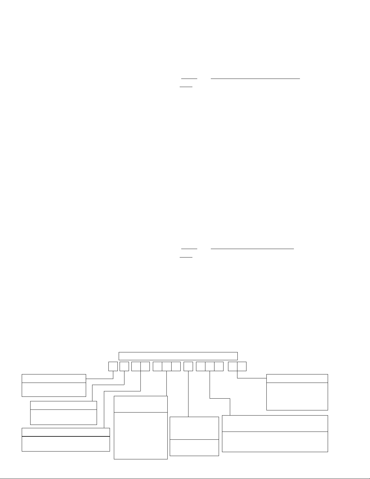
NOMENCLATURE
1 N A 0 602 6N
D
PRODUCT CATEGORY
D = Single Package
Air Conditioner
PRODUCT GENERATION
1 = 1st Generation
2 = 2nd Generation
PRODUCT IDENTIFIER
NA = 10 SEER
Gas Heat / Electric Cool
2 Unitary Products Group
NOMINAL COOLING
CAPACITY(MBH)
018 = 18,000 BTUH
024 = 24,000 BTUH
030 = 30,000 BTUH
036 = 36,000 BTUH
042 = 42,000 BTUH
048 = 48,000 BTUH
060 = 60,000 BTUH
0 34
FACTORY
INSTALLED
GAS HEAT
N = Natural Gas
Heat Installed
VOLTAGE CODE
06 = 208/230-1-60
25 = 208/230-3-60
46 = 460-3-60
58 = 575-3-60
NOMINAL GAS HEATING
OUTPUT CAPACITY
036 = 36,000 BTUH 065 = 65,000 BTUH
056 = 56,000 BTUH 090 = 90,000 BTUH
072 = 72,000 BTUH 110 = 110,000 BTUH
Page 3
INSTALLATION
Not suitable for use with conventional venting systems.
LIMITATIONS
These units must be installed in accordance with the following
national and local safety codes.
1. National Electrical Code ANSI/NFPS No. 70 or Canadian
Electrical Code Part 1, C22.1 (latest editions).
2. NationalFuel Gas Code Z223.1 or CAN/CGAB149.1 or .2
Installation Code.
3. Local gas utility requirements.
4. Local plumbing and waste water codes and other applica
ble local codes.
Refer to Table1 for unit application data and to Table2 for gas
heat application data.
If componentsare to be added to a unit to meetlocal codes, they
aretobe installedatthe dealer'sand/orthecustomer'sexpense.
Size of unit for proposed installation should be based on heat
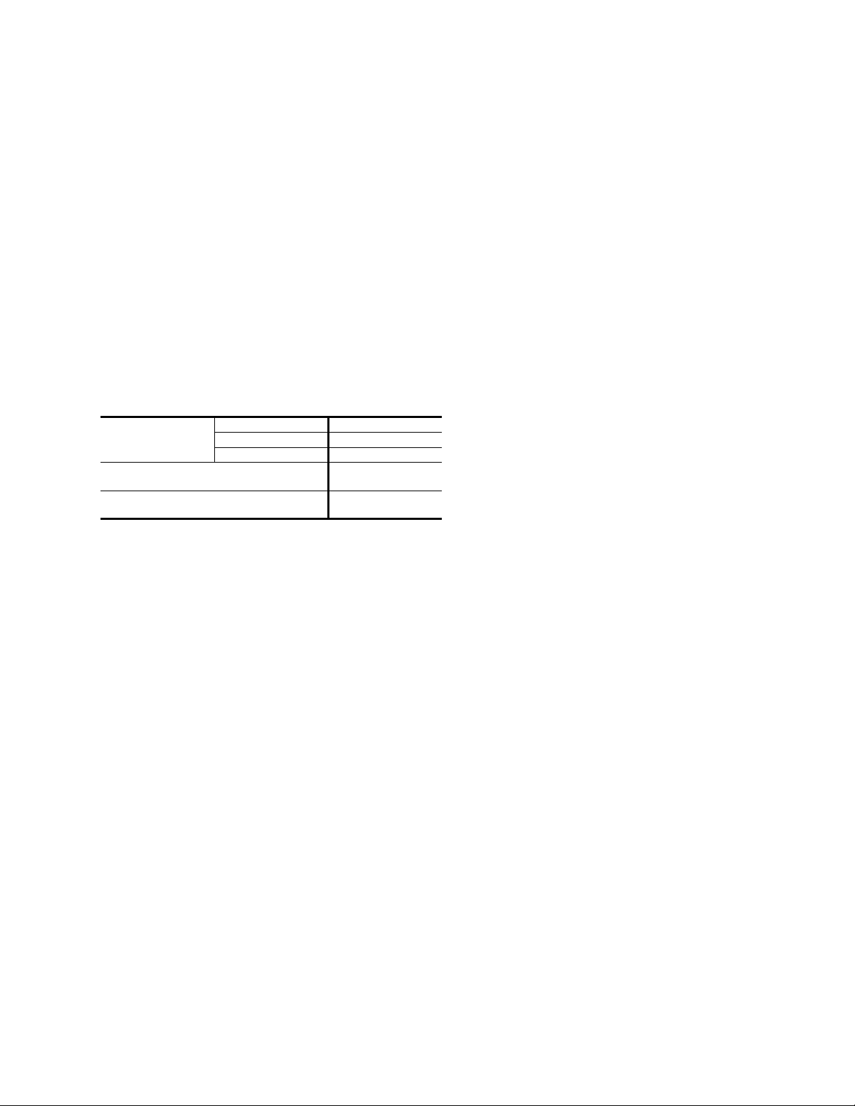
TABLE 1 - UNIT APPLICATION DATA
2
/ Max.
208/230V
Voltage Variation
Min. / Max
Wet Bulb Temperature (°F) of Air on
Evaporator Coil, Min. / Max.
Dry Bulb Temperature (°F) of Air on
Condenser Coil, Min.
1 Rated in accordance with ARI Standard 110, utilization"A".
2
A low ambient accessory is available for operation down to 0°F
3
“T1" transformer primary tap must be moved from the 230 volt connection to the 208 volt
connection for low voltage applications of 208 volt and below.
.1
loss/heat gain calculations made in accordance with industry
recognized procedures identified by the Air Conditioning Contractors of America.
LOCATION
3
460V 414 / 504
575V 518 / 630
187 / 253
57 / 72
45 / 120
3
035-18265-001-A-0202
gle iron frame providing adequate support under the
compressor/condenser section.
5. Maintain level tolerance of unit to 1/8" maximum.
RIGGING OR HANDLING
Care must be exercised whenmovingthe unit. Do not remove
anypackaging untilthe unit isnear theplace ofinstallation. Rig
unit with slings placed under the unit. Spreader bars of suffi
cient length should be used across the top of the unit.
BEFORE LIFTING AUNIT, MAKE SURE THAT ITS WEIGHT
IS DISTRIBUTED EQUALLY ON THE CABLES SO THAT IT
WILL LIFT EVENLY.
Units may also be movedorlifted with a fork-lift. Slotted open
ings in theskid are provided for this purpose. Forks must pass
completely through the base.
RefertoTable7forunit weightsandto Figure4forapproximate
center of gravity.
CLEARANCES
All units require certain clearances for proper operation and
service. Refer to Figure 5 for the clearances required for combustion, construction, servicing and proper unit operation.
WARNING:Donot permit overhanging structures or shrubs to
obstruct the condenser air discharge, combustion
air inlet or vent outlet.
DUCT WORK
Theseunits areadaptable todownflow useas wellas rearsupply and return air duct openings. To convert to downflow, use
the following steps:
-
-
Use the following guidelines to select a suitable location for
these units.
1. Unit is designed for outdoor installation only.
2. Condenser must have an unlimited supply of air. Where a
choiceof locationispossible, positionunit oneithernorth or
east side of building.
WARNING:Excessive exposure of this furnace to contami
nated combustion air mayresult equipment dam
age or personal injury. Typical contaminates
include: permanent wave solutions, chlorinated
1. Remove the duct covers found in the bottom return and
supply air duct openings. There are four (4) screws secur
ing each duct cover (save these screws to use later).
2. Install the duct covers, removed in step one, to the rear
supply and return air duct openings. Secure with the four
(4) screws used in step one.
3. Seal the duct covers with silicone caulk.
-
Duct work should be designed and sized according to the
-
methods of the Air Conditioning Contractors of America
(ACCA), as set forth in their Manual D.
waxes and cleaners, chlorine based swimming
poolchemicals, watersoftening chemicals,carbon
tetrachloride, Halogen type refrigerants, cleaning
solvents (e.g. perchloroethylene), printing inks,
paint removers, varnishes, hydrochloric acid, ce
ments and glues, antistatic fabric softeners for
clothes dryers, masonry acid washing materials.
3. For ground level installation, a level pad or slab should be
used.The thicknessandsize ofthe padorslab usedshould
meet local codes and unit weight. Do not tie the slab to the
A closed return duct system shall be used. This shall not pre
clude use of economizers or ventilation air intake. Flexible
joints may be used in the supply and return duct work to mini
-
mize the transmission of noise.
CAUTION: When fastening duct work to the side duct flanges on
theunit,insertthescrews throughtheduct flangesonly.
DONOT insertthescrews throughthecasing. Outdoor
duct work must be insulated and waterproofed.
building foundation.
4. For roof top installation, be sure the structure will support
NOTE: Be sure to note supply and return openings.
the weight of the unit plus any field installed components.
Unitmust beinstalledon alevelroofcurbor appropriatean
Unitary Products Group 3
-
-
-
-
Page 4
035-18265-001-A-0202
Refer to Figure 5 for information concerning rear and bottom
supply and return air duct openings.
ROOF CURB
Onapplications whena roofcurb isused,theunitmust beposi
tioned on the curb so the front of the unit is tight against the
curb.
FILTERS
Singlephase unitsare shippedwithout afilter and isthe responsi
bilityof the installerto securea filter inthe returnair ductwork or
install a Filter/Frame Kit (1FF0110 for the D1NA018 thru
D1NA042 and 1FF0112 for the D1NA048 and D2NA060).
A filter rack and filters are standard on three phase units.
NOTE: Filters on the D1NA048 and D2NA060 units require
5
the use of a
" nut driver for removal.
16
Filters must always be used and must be kept clean. When fil
ters become dirt laden, insufficient air will be delivered by the
blower,decreasingyour unitsefficiencyand increasingoperat
ing costs and wear-and-tear on the unit and controls.
Filters should be checked monthly especially since this unit is
used for both heating and cooling.
CONDENSATE DRAIN
A condensate trap is recommended to be installed in the condensatedrain. The plumbingmust conform tolocal codes.Use
a sealing compound on male pipe threads. Install the condensate drain line (
3
“ NPTF) to spill into an open drain.
4
SERVICE ACCESS
Accessto allserviceablecomponents isprovided bythefollowing removable panels:
•
Blower compartment
•
Gas control/electrical service access
** = Minimum wire size of 18 AWG
wire shuold be used for all field
installed 24 volt wire.
PROGRAMABLE
THERMOSTAT ONLY
THERMOSTAT
R
G
W
C
CONTROL WIRING
R
G
YY
W
C
Refer to Figure5 for location of these access panels and mini
mum clearances.
THERMOSTAT
The room thermostat should be located on an inside wall ap
-
proximately 56" above the floor where it will not be subject to
drafts, sun exposure or heat from electrical fixtures or appli
ances. Follow manufacturer's instructions enclosed with the
thermostatfor generalinstallationprocedure. Fourcolor coded
insulated wires (minimum #18 AWG) should be used to con
nect thermostat to unit. See Figure 1.
-
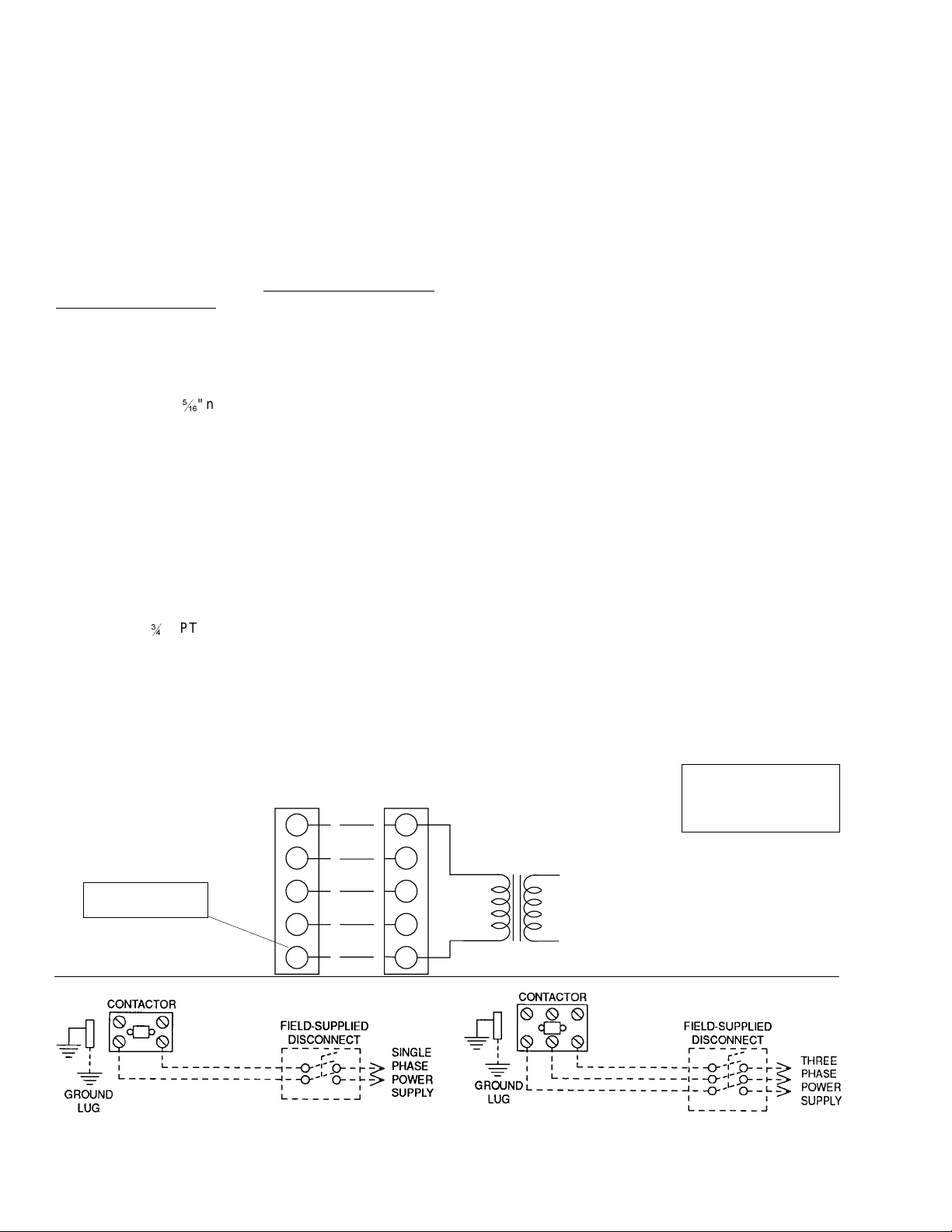
POWER AND CONTROL WIRING
Fieldwiringtotheunit mustconformto provisionsofthe current
N.E.C. ANSI/NFPANo. 70 or C.E.C. and/or local ordinances.
Theunit mustbe electricallygrounded inaccordance withlocal
codes or, in their absence, with the N.E.C./C.E.C. Voltagetol
erances which must be maintained at the compressor termi
nalsduring startingandrunning conditionsare indicatedon the
unit Rating Plate and Table 8.
The wiring entering the cabinet must be provided with me
-
chanical strain relief.
Afused disconnect switch should be fieldprovided for the unit. If
any of the wire supplied with the unit must be replaced, replacement wire must be of the type shown on the wiring diagram.
Electrical line must be sized properly to carry the load. Each
unit must be wired with a separate branch circuit fed directly
from the meter panel and properly fused.
Referto Figure 1for typical fieldwiring and tothe appropriate unit
wiring diagram for control circuit and power wiring information.
COMPRESSORS
Unitsareshipped withcompressormountings factory-adjusted
for shipping. CAUTION: Loosen compressor mounting bolts
half turn before operating unit.
NOTE:
HEATANTICIPATOR
SHOULD BE SET AT0.35
AMPS FOR ALL MODELS.
CAUTION: Label all wires prior
to disconnection when
24 VOLT
TRANSFORMER
servicing controls.
Wiring errors can cause
improper and dangerous
operation. Verify proper
operation after servicing.
-
-
-
-
-
-
-
POWER
WIRING
REFER TO ELECTRICAL
DATA TABLES TO SIZE THE
DISCONNECT SWITCH,
WIRING & OVERCURRENT
FIG. 1 - TYPICAL FIELD WIRING DIAGRAM
4 Unitary Products Group
REFER TO ELECTRICAL
DATA TABLES TO SIZE THE
DISCONNECT SWITCH,
WIRING & OVERCURRENT
Page 5

Scroll compressors operate in one direction only. If a three
phase scroll compressor is experiencing:
Low amperage draw
•
Similar discharge and suction pressures
•
Increased noise level
•
then the compressor is operating in reverse. To correct this
condition,switch anytwo (2)line voltageleads atthe contactor.
Please note, single phase scroll compressor will start and run
in one direction only. The reverse operation is not a concern.
035-18265-001-A-0202
GAS PIPING
Proper sizing ofgas piping depends on the cubic feet perhour
ofgasflowrequired,specific gravityofthe gasandthe lengthof
run. “National Fuel Gas Code” Z223.1 or CAN/CGAB149.1 or
.2 should be followed in all cases unless superseded by local
codesorgas companyrequirements.Referto Tables 4and5.
The heatingvalueof the gas may differ withlocality. Thevalue
should be checked with the local gas utility.
COMBUSTION DISCHARGE
TABLE 2 - NATURALGAS APPLICATION DATA
Input
Capacity
(Mbh)
Output
Capacity
3
(Mbh)
45 36
70 56
1
1
2 &
3 &
90 72 3 &
Available
On
Models
, 2,
2
2
1
TON
3
2
1
2
2
1
3
2
1
3
2
Gas
Number
1
Rate
1
2
Ft.3/Hr.
, 3 &
Burners
42 2 25 55
TON 65 3 30 60
TON 65 3 25 55
TON 84 4 30 60
80 64 4 & 5 TON 74 3 25 55
108 86 4 & 5 TON 100 4 30 60
135 108 4 & 5 TON 126 5 35 65
1 Based on 1075 BTU/Ft.3.
2 The air flow must be adjusted to obtain a temperature rise within the range shown.
Continuous return air temperatures should not be below 55°F.
3 Heating capacity valid for elevations up to 2000 feet above sea level. For elevations
above 2000 feet, rated capacity should be reduced by 4% for each 1000 feet above sea
level.
of
Temp. Rise °F
At Full Input
Min. Max.
TABLE 3 - PROPANE (LP) GAS APPLICATION DATA
Input
Capacity
(Mbh)
Output
Capacity
3
(Mbh)
45 36
70 56
1
1
2
2 &
3 &
90 72 3 &
Available
On
Models
, 2,
2
1
TON
3
2
1
2
2
1
3
2
1
3
2
Gas
Number
1
Rate
1
2
Ft.3/Hr.
, 3 &
Burners
18 2 25 55
TON 28 3 30 60
TON 28 3 25 55
TON 36 4 30 60
80 64 4 & 5 TON 32 3 25 55
108 86 4 & 5 TON 43 4 30 60
135 108 4 & 5 TON 54 5 35 65
1 Based on 2500 BTU/Ft.3.
2 The air flow must be adjusted to obtain a temperature rise within the range shown.
Continuous return air temperatures should not be below 55°F.
3 Heating capacity valid for elevations up to 2000 feet above sea level. For elevations
above 2000 feet, rated capacity should be reduced by 4% for each 1000 feet above sea
level.
4 Propane applications are accomplished by field installation of a Propane Conversion
Accessory, Model 1NP0805 for 1.5 thru 3.5 ton units and Model 1NP0806 for 4 and 5
ton units.
of
Temp. Rise °F
At Full Input
Min. Max.
NOTE: Theremay bea localgasutilityrequirementspecifying
a minimum diameter for gas piping. All units require a
2
1/2 inch pipe connection at the gas valve.
GAS CONNECTION
The gas supply line can be routed through the hole located on
theleft sideof the unit.Refer toFigure5 tolocate theseaccess
openings. Typical supply piping arrangements are shown in
Figure 2.
AUTOMATIC
GAS VALVE
121
UNION
x
2
121
GAS COCK
x
2
2
1
2
DRIP LEG
FIG. 2 - EXTERNAL SUPPLY CONNECTION
EXTERNAL SHUT-OFF
Gas piping recommendations:
1. Adrip leg and a ground joint union must be installed in the
gas piping.
2. Whenrequiredby localcodes, amanual shut-offvalvemay
have to be installed outside of the unit.
- 14 NPT
TABLE 4 - NATURALGAS PIPE SIZING CHART
Length
in
Feet
1/2 in. 3/4 in. 1 in. 1-1/4 in.
10 132 278 520 1,050
20 92 190 350 730
30 73 152 285 590
40 63 130 245 500
50 56 115 215 440
60 50 105 195 400
70 46 96 180 370
80 43 90 170 350
90 40 84 160 320
100 38 79 150 305
Maximum Capacity of Pipe in Cubic Feet of Gas Per Hour (Based Upon APressure Drop
of 0.3 Inch Water Column and 0.6 Specific Gravity Gas).
Nominal Inches Iron Pipe Size
TABLE 5 - PROPANE (LP) GAS PIPE SIZING CHART
Length
in
Feet
1/2 in. 3/4 in. 1 in. 1-1/4 in.
10 275 567 1,071 2,205
20 189 393 732 1,496
30 152 315 590 1,212
40 129 267 504 1,039
50 114 237 448 913
60 103 217 409 834
70 96 196 378 771
80 89 185 346 724
90 83 173 322 677
100 78 162 307 630
Maximum Capacity of Pipe in Thousands of BTU Per Hour (Based Upon APressure Drop
of 0.5 Inch Water Column).
Nominal Inches Iron Pipe Size
Unitary Products Group 5
Page 6
035-18265-001-A-0202
3. Use wrought iron or steel pipe for all gas lines. Pipe dope
should be applied sparingly to male threads only.
CAUTION: If flexible stainless steel tubing is allowed by the
authority having jurisdiction, wrought iron or steel
pipe must be installed at the gas valve and extend a
minimumoftwo (2)inchesoutside oftheunit casing.
FLUE VENT HOOD
Theflue venthoodwithscreenis notshipped attached.Thishood
must beinstalled to assure proper unitoperation. The hood must
be fastened to the outside of the side gas control/electrical com
partment with the screws provided in the bag attached to the in
side of the gas control/electrical compartment, see Figure 3.
-
-
WARNING:Naturalgas may contain some propane. Propane,
being an excellent solvent, will quickly dissolve
white lead or most standard commercial com
pounds. Therefore, a special pipe dope must be
applied when wrought iron or steel pipe is used.
Shellacbase compoundssuchas GaskolacorSta
lastic, and compounds such as Rectorseal #5,
Clyde's or John Crane may be used.
4. Allpipingshould becleaned ofdirtandscaleby hammering
onthe outsideof the pipeand blowingout theloose dirtand
scale. Beforeinitial start-up, besure that all ofthe gas lines
external to the unit have been purged of air.
5. The gas supply should be a separate line and installed in ac
cordance with all safety codes as prescribed under “Limita
tions”. Afterthe gas connections have been completed,open
the main shut-off valve admitting normal gas pressure to the
mains. Check all joints for leaks with soap solution or other
material suitable for the purpose. NEVER USE A FLAME.
6. The furnace and its individual manual shut-off valve must
be disconnected from the gas supply piping system during
any pressure testing ofthatsystem at test pressures in excess of 1/2 psig (3.48 kPa).
The furnace must be isoulated from the gas supply piping
system by closing its individual manual shut-off valve during any pressuretesting of the gas supply piping systemat
test pressures equal to or less than 1/2 psig (3.48 kPa).
The unit iscontrolled by a conventional four wire heating/cool
ing thermostat common to this class of equipment.
-
-
WARNING: FLUE HOOD SURFACES
MAY BE HOT.
VENT OUTLET SCREEN
FLUE VEN T O U TLET
AIR HOOD
-
-
FIG. 3 - FLUE VENT OUTLET AIR HOOD
CAUTION
The flueexhaust hood must be properlyinstalled and within the
recommended clearances.Further communications and action
must be given to the home or building owner(s) to eleiminate
any unauthorized humon contact around this area during the
heating cycle. Flue hood surface and immediate area is designedtooperate athightemperatures duringtheheating cycle.
-
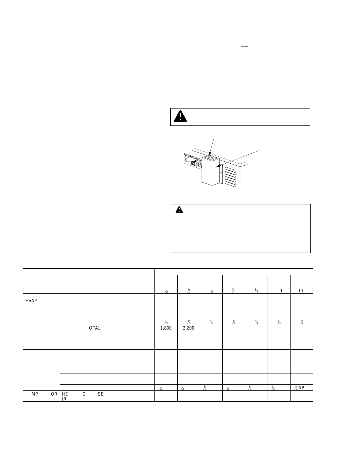
TABLE 6 - PHYSICAL DATA
1
2
DNA
3
4
1
4
NPTI
1
2
3
4
1
4
NPTI
1.0 1.0
1
4
1
NPTI
2
1
2
NPTI
EVAPORATOR
BLOWER
EVAPORATOR
COIL
CONDENSER
FAN
CONDENSER
COIL
MODELS
CENTRIFUGAL BLOWER (Dia. x Wd. in.) 10 X 8 10 X 8 10 X 8 11 x 10 11 x 10 12 x 11 12 x 11
FAN MOTOR HP(Three Speed)
ROWS DEEP 2222333
FINS PER INCH 14 13 13 15 13 13 13
FACE AREA(Sq. Ft.) 2.25 3.5 3.5 3.5 3.5 4.5 4.5
PROPELLER DIA. (in.) 22 22 22 22 22 22 22
FAN MOTOR HP
NOM. CFM TOTAL 1,800 2,200 2,400 2,400 2,400 3,000 3,000
ROWS DEEP 1111111
FINS PER INCH 13 13 16 20 20 20 20
FACE AREA(Sq. Ft.) 8.3 8.3 11.7 11.7 11.7 14.8 14.8
018 024 030 036 042 048 060
1
2
1
4
1
2
1
4
1
2
1
4
CHARGE REFRIGERANT 22 (lbs./oz.) 3 / 2 3 / 6 4 / 12 4 / 3 4 / 12 6 / 0 5 / 4
FILTER* FACE AREA(Sq. Ft.) / SIZE (NOMINAL) 2.6/20x20 2.6/20x20 2.6/20x20 2.6/20x20 2.6/20x20 3.3/20x12 3.3/20x12
NATURALGAS BURNER ORIFICE NO.
FURNACE
SECTION
(Qty./Drill size)
PROPANE BURNER ORIFICE NO.
(Qty./Drill size)
GAS CONNECTION SIZE
COMPRESSOR
TYPE
* = Three phase 018 thru 042 size units are supplied with one (1) filter and on three phase 048 and 060 size units two (2) filters are supplied. Single phase units are shipped without filters.
See “FILTERS” on page 4.
HERMETICALLYSEALED
(R = RECIPROCATING, S = Scroll)
43 43 43 43 43 40 40
55 55 55 55 55 53 53
1
2
NPTI
1
2
NPTI
1
2
NPTI
RRRRRSS
1
4
6 Unitary Products Group
Page 7

TABLE 7 - UNIT WEIGHTS
MODEL
DNA
UNIT
SHIPPING
WEIGHT
(lbs.)
UNIT
OPERATING
WEIGHT
(lbs.)
018 365 360 91 88 89 92
024 365 360 91 88 89 92
030 395 390 98 95 96 99
036 400 395 100 96 98 101
042 405 410 104 100 101 105
048 475 470 119 115 116 120
060 480 475 120 116 117 122
CORNER OPERATING WEIGHTS
(lbs., location, see Figure 4)
“A” “B” “C” “D”
035-18265-001-A-0202
CORNER “D”
CENTER OF GRAVITY
CORNER “C”
CORNER “A”
FRONT
OF
UNIT
1
47
49
1
8
25
FIG. 4 - CENTER OF GRAVITY
24
CORNER “B”
4
TABLE 8 - ELECTRICAL DATA
SUPPLY
AIR
BLOWER
MOTOR,
FLA
MINIMUM
CIRCUIT
AMPACITY
MODEL
DNA
POWER SUP
PLY
VOLTAGE
LIMITATIONS
-
1
COMPRESSOR
MIN. MAX. RLA LRA
COND.
FAN
MOTOR,
FLA
018 208/230-1-60 187 253 9.0 48.0 1.1 2.2 14.5 20 20 .96 40
024 208/230-1-60 187 253 11.5 60.0 1.1 2.2 17.7 25 25 .96 40
030 208/230-1-60 187 253 14.7 73.0 1.1 2.2 21.7 30 30 .96 40
036 208/230-1-60 187 253 17.3 94.0 1.1 3.5 26.2 35 35 .96 40
042 208/230-1-60 187 253 20.5 120.0 1.1 3.5 30.2 40 40 .96 40
048 208/230-1-60 187 253 24.4 140.0 1.3 7.0 38.8 50 50 .96 40
060 208/230-1-60 187 253 28.9 175.0 1.3 7.0 44.4 60 60 .96 40
036 208/230-3-60 187 253 10.9 78.0 1.1 3.5 18.2 25 25 .96 75
042 208/230-3-60 187 253 14.1 110.0 1.1 3.5 22.2 30 30 .96 75
048 208/230-3-60 187 253 14.1 105 1.3 7.0 25.9 35 35 .96 75
060 208/230-3-60 187 253 15.5 125 1.3 7.0 29.5 40 40 .96 75
036 460-3-60 414 504 5.8 40.0 0.6 1.8 9.6 15 15 .96 75
042 460-3-60 414 504 7.1 54.0 0.6 1.8 11.2 15 15 .96 75
048 460-3-60 414 504 7.1 55.0 0.7 3.5 13.1 20 20 .96 75
060 460-3-60 414 504 8.8 66.5 0.7 3.5 15.4 20 20 .96 75
036 575-3-60 518 630 4.5 32.0 0.4 1.5 7.5 15 15 .96 75
042 575-3-60 518 630 5.8 44.0 0.4 1.5 9.1 15 15 .96 75
048 575-3-60 518 630 5.7 45.0 0.6 2.8 10.5 15 15 .96 75
060 575-3-60 518 630 7.1 50.0 0.6 2.8 12.3 15 15 .96 75
Note; Electrical data based on 104°F outdoor air ambient temperature.
1
= Rated in accordance with ARI Standard 110, utilization range “A”.
3
= If economizer or motorized damper are to be used, 75 VAis required. Refer to price pages for future details.
2
= Dual element, time delay type.
MAX.
FUSE
SIZE,
AMPS
2
MAX.
HACR
BREAKER
SIZE,
AMPS
UNIT
POWER
FACTOR
TRANSFORMER
SIZE (VA)
3
Unitary Products Group 7
Page 8

035-18265-001-A-0202
1
7
GAS SUPPLY
HIGH VOLTAGE
CONN.
1
3
32
“ DIA.
KNOCKOUT
VENT AIR OUTLET HOOD
BLOWER
SERVICE ACCESS
COMPARTMENT PANEL
GAS SUPPLY
1
“ NPTI CONNECTION)
(
2
UNIT CONDENSATE
CONNECTION
1
“ DIA. HOLE
1
4
3
“ NPTI
4
(TRAP RECOMMENDED)
HIGH VOLTAGE CONN.
3
“ DIA. KNOCKOUT
8
HIGH VOLTAGE CONN.
“ DIA. KNOCKOUT
8
1
(
2
1
“ DIA. KNOCKOUT
1
4
“ NPTI CONNECTION)
LOW VOLTAGE CONN.
3
“ DIA. KNOCKOUT x
1
8
7
8
8
11
UNIT
SIZE
018 THRU 042
048 AND 060
DIMENSION
“A” “B”
1
33
18
2
1
41
23
2
1
4
3
8
CONDENSER COIL
A
3
B
3
3
4
1
2
2
2
8
(OVERALL)
REFRIGERANT
CONNECTIONS
1
1
2
5
2
8
1
3
2
1
47
4
7
“ HOLE
8
1
19
4
7
8
(OVERALL)
FRONT
GAS SUPPLY
1
(
LOW VOLTAGE CONN.
7
“ DIA. KNOCKOUT
8
5
1
“ NPTI CONNECTION)
2
“ DIA. KNOCKOUT
8
3
5
8
11
3
12
4
1
49
8
(OVERALL)
COMBUSTION AIR
INLET LOUVERS
FRONT
GAS/ELECTRIC CONTROL
SERVICE ACCESS
COMPARTMENT PANEL
All dimensions are in inches. They are
subject to change without notice. Certified
dimensions will be provided upon request.
SIDE SUPPLY
AIR OPENING
15
5
4
8
3
26
4
6
CONDENSATE
3
DRAIN
“ NPTI
4
BOTTOM SUPPLY
AIR OPENING
CLEARANCES
(Minimum)
Front 36"
Back 0"
Left Side (Filter Access) 24"
Right Side 12"
Below Unit
Above Unit
1
Units may be installed on combustible floors made from wood or class
A, B or C roof covering material.
2
Units must be installed outdoors. Overhanging structures or shrubs
should not obstruct condenser air discharge outlet.
NOTE:
1
2
0"
36" (For Condenser
Air Discharge)
A 1" clearance must be provided between any combustible material
and the supply air ductwork.
The products of combustion must not be allowed to accumulate
within a confined space and recirculate.
CONDENSER
COIL
3
1
4
15
28
1
14
2
REAR
3
3
8
SIDE RETURN
14
28
3
8
1
2
AIR OPENING
3
2
8
15
14
1
2
1
3
2
4
9
16
1
3
2
3
1
4
3
1
4
BOTTOM RETURN
AIR OPENING
FIG. 5 - DIMENSIONS AND CLEARANCES
8 Unitary Products Group
Page 9

SEQUENCE OF OPERATION
HEATING
When the thermostat calls for “HEAT”,the thermostat terminal
“W” is energized, energizing the combustion air blower.
035-18265-001-A-0202
switches must bemanuallyreset). The circulating fan remains
energized for the selected heat delay off timing.
Normal operation of the system resumes.
COOLING
After airflow is established, the air proving switch closes, the
hot surface ignitor is energized and the pilot valve opens ignit
ing the pilot flame. The system will try to light the pilot for 90
seconds. After 90 seconds, the pilot valve will close and the
system will retry in 5 minutes.
The flame rod senses a flame and de-energizes the ignitor
opening the main gas valve and the main burners light.
30seconds afterthemainburnerslight thecirculating fanis en
ergized at the heating speed.
Whenthe thermostat issatisfied, terminal “W”isde-energized,
de-energizing the ignition system closing the gas valve.
After a 5 second postpurge timing period, the combustion air
blower is de-energized and the heat fan off timing begins.
Whenthis fieldselected heatfanofftiming iscompletedthe cir
culating fan is de-energized.
If the primary, rollout or auxiliary limit switches open, the thermostat and ignition system is de-energized and the gas valve
closes. The combustion blower and the circulating fan, at heat
speed, are energized.
The combustion blower remains energized for the 5 second
postpurge timing period if the primary, rollout or auxiliary limit
switches remake the contact (the rollout and auxiliary limit
When the thermostat calls for “COOL”, the thermostat termi
nals “G” and “Y” are energized signaling the compressor and
outdoor fan to run.
Aftera coolfan ondelay timingof 2seconds, thecirculating fan
is energized at cooling speed.
When thethermostat is satisfied, terminals“G” and “Y” are deenergized, de-energizing the compressor and outdoor fan.
After a cool fan off delay timing of 30 seconds the circulating
fan is de-energized.
CIRCULATING FAN
When the thermostat calls for “FAN”, the thermostat terminal
“G” is energized signaling the circulating fan to run at the heat
speed 2 seconds after the “G” terminal is energized.
Ifacall for“HEAT”occurs,thecirculating fancontinuesto runat
the heat speed.
If a call for “COOL” occurs, the circulating fan switches to cool
speed after a 4 second delay.
When the thermostat ends the call for “FAN”, the thermostat
terminal“G”is de-energized,de-energizingthe circulatingfan.
-
START-UP
PRE-START CHECK LIST
Complete the following checks before starting the unit.
1. Checkthe type of gas being supplied. Be sure that it is the
same as listed on the unit nameplate.
2. Makesure that the vent outlet air hoods has been properly
installed.
OPERATING INSTRUCTIONS
1. STOP! Read the information on the unit safety label.
2. Set the thermostat to the “OFF” position.
3. Turn off all electrical power to the unit.
4. DO NOT try to light the burners by hand. This appliance is
equipped with an ignition device which automatically lights
the burners.
5. Remove the access panel.
6. Turn the gas valve switch to the “OFF” position.
7. Wait five (5) minutes to clear out any gas. If you then smell
gas, STOP! Follow “B” in the information on the unit safety
label. If you don't smell gas, go to the next step.
Unitary Products Group 9
8. Turn the gas valve switch to the “ON” position.
9. Replace the control access panel.
10.Turn on all electric power to the unit.
11.Set the thermostat to the desired setting.
12.If the unit will not operate, follow the instructions “To Turn
Off Gas To Appliance” and call your service technician or
gas supplier.
TO TURN OFF GAS TO UNIT
1. Set the thermostat to the “OFF” position.
2. Turn offall electric powertothe appliance if serviceis to be
performed.
3. Remove the control access panel.
4. Turn the gas valve switch to the “OFF” position. DO NOT
FORCE.
5. Replace the control access panel.
POST-START CHECK LIST (GAS)
Afterthe entirecontrol circuithas beenenergized andthe heat
ing section is operating, make the following checks:
1. Checkfor gas leaks in the unit piping as well as the supply
piping.
-
Page 10

035-18265-001-A-0202
2. Check for correct manifold gas pressures. See “Checking
Gas Input”.
3. Checkthe supply gas pressure. It must be within the limits
shown on rating nameplate. Supply pressure should be
checkedwith all gasappliances in thebuilding atfull fire. At
notime shouldthestandby gasline pressureexceed 10.5",
nor the operating pressure drop below 4.5" for natural gas
units. If gas pressureisoutside these limits, contact the lo
cal gas utility for corrective action.
MANIFOLD GAS PRESSURE ADJUSTMENT
Small adjustmentstothe gas flow may be made by turning the
pressureregulator adjustingscrew ontheautomatic gasvalve.
Refer to Figure 6.
CONTROL
ELECTRICAL
CONNECTION
MANUAL GAS
SW ITCH
(S H O W N IN " O F F
POSITION )
IGNITO R ELECTRICAL
CONNECTION
MANIFOLD
PRESSUR E
TAP
GROUND
TER MINAL
2. Removethe burner assembly from the manifold assembly
by moving the burner assembly forward, turn at an angle
and pull back.
3. Burners are now accessible for service.
HOT SURFACE PILOT INSTRUCTIONS
To check, adjust or remove the hot surface pilot assembly,
CLOSE THE MAIN MANUAL SHUT-OFF VALVE AND SHUT
OFF ALL POWER TO THE UNIT.
3
The pilot flame shouldenvelope
sensor and not contain any yellow color, see Figure 7.
3
8
3/8
inch of the endofthe flame
8
1/2-14 N PT
(O U T L E T)
PILOT G AS
CONNECTION
PILOT
ADJUSTMENT
LINE PRESSUR E TAP
M ANIFO LD PRESSU RE
ADJUSTMENT
(REM OVE CAP)
1/2 - 14 N PT
(IN L E T )
VENT PR ESSURE LIM ITER
FIG. 6 - GAS VALVE
Adjust as follows:
1. Removethecapfrom thevalve body.See Figure6 for loca
tion.
2. To decrease the gas pressure, turn the adjusting screw
counterclockwise.
3. To increase the gas pressure, turn the adjusting screw
clockwise.
FIG. 7 - PROPER FLAME ADJUSTMENT
To adjust the pilot flame:
1. Remove the pilot adjustment cover screw.
2. Adjustthe pilot adjustment screw to achieve the proper pilot flame.
3. Replace the pilot adjustment cover screw after the pilot
flame is set.
To remove the hot surface pilot assembly:
1. Disconnectthe wiring from thegas valve to the hotsurface
pilot assembly.
2. Removethe two (2)#8 screws holding thehot surface pilot
assembly in place.
3. Remove the hot surface pilot assembly.
To removethehot surfaceignitorand flamesensorassembly:
1. Removethe clip attachingthe ignitor andsensor assembly
as shown in Figure 8.
-
NOTE: Thecorrect manifoldpressure fornatural gasfurnaces
is3.5 IWG±0.2. Thecorrectmanifold pressurefor pro
-
pane (LP) is 10.0 IWG ±0.2.
BURNER INSTRUCTIONS
FIG. 8 - IGNITOR AND FLAME SENSOR ASSEMBLY
To check or change the burners, CLOSE THE MAIN MANUAL
SHUT-OFFV ALVEAND SHUTOFFALLPOWERTO THEUNIT.
1. Remove the two (2) #8 screws holding each burner in
place.
10 Unitary Products Group
Lift the pilot and sensor from the assembly. Care must be
2.
takennot todamage thepilot orsensorwhen removingthis
assembly.
Page 11

3. After maintenance of the pilot assembly, always measure
theresistance across theignitor.Ifthe resistanceis greater
than 10 ohms, discard the ignitor and replace it with a new
ignitor.
ADJUSTMENT OF TEMPERATURE RISE
°F Temp. Rise =
BTUH Output
1.08 x CFM
(OR) CFM =
The temperature rise (or temperature difference between the
return air and the heated air from the furnace) must lie within
the range shown on the rating plate and the data in Tables 2
and 3.
After the temperature rise has been determined, the CFM can
be calculated as follows:
After about 20 minutes of operation, determine the furnace
temperature rise. Take readings of both the return air and the
heated air in the ducts about six feet from the furnace where
they will not be affected by radiant heat. Increase
CFM to decrease
CFM to increase
the temperature rise; decrease the blower
the rise.
DIRECT DRIVE BLOWER
All units have direct drive multi-speed blower motors. Refer to
the unit wiring diagram and connect the blower motor for the
desired CFM.
BTUH Output
1.08 x °F Temp. Rise
the blower
CHECKING GAS INPUT
NATURALGAS
1. Turnoffallothergas appliancesconnectedto thegasmeter.
2. With thefurnace turned on,measurethe time neededforone
revolutionof thehand onthe smallestdialon themeter.Atypical gas meter usually has a 1/2 or a 1 cubic foot test dial.
3. Using the number of seconds for each revolution and the
sizeof thetest dialincrement, findthe cubicfeet ofgascon
sumed per hour from Table 9.
035-18265-001-A-0202
TABLE 9 - GAS RATE- CUBIC FEET PER HOUR
Seconds
for One
Rev.
10 180 360
12 150 300
14 129 257
16 113 225
18 100 200
20 90 180
22 82 164
24 75 150
26 69 138
28 64 129
30 60 120
32 56 113
34 53 106
36 50 100
38 47 95
40 45 90
42 43 86
44 41 82
46 39 78
48 37 75
50 36 72
52 35 69
54 34 67
56 32 64
58 31 62
Example: By actual measurement, it takes 38 seconds for the hand on the 1-cubic foot dial to
make a revolution with just a 100,000 BTUH furnace running. Using this information, locate38
seconds in the first column of Table9. Read across to the column headed “1 Cubic Foot,”
where you will see that 95 cubic feet of gas per hour are consumedby the furnace at that rate.
Multiply 95 x 1050 (the BTU rating of the gas obtained from the local gas company). The result
is 99,750 BTUH, which is close to the100,000 BTUH rating of the furnace.
60 30 60
Size of Test Dial
1/2 cu. ft. 1 cu. ft.
-
If the actual input is not within 5% of the furnace rating with al
lowance being made forthe permissible range of the regulator
setting,replacethe orificespudswith spudsofthe propersize.
NOTE: Tofindthe BTUinput, multiplythenumber ofcubicfeet of
gasconsumedper hour bythe BTU contentof the gasin
your particular locality. (Contact your gas company for
this information since it varies widely from city to city.)
SECURE OWNER'S APPROVAL
When the system is functioning properly ,secure the owner's ap
proval. Show him the location of all disconnect switches and the
thermostat. Teachhim how to start and stop the unit and how to
adjust temperature settings within the limitations of the system.
Advise himthat the flue exhausthood surface and theimmediate
area will experience high temperatures during the heating cycle.
All unauthorized personnel and debris must be kept away from
this area.
Unitary Products Group 11
-
Page 12

035-18265-001-A-0202
MAINTENANCE
NORMAL MAINTENANCE
WARNING:Prior to any of the following maintenance proce
dures, shut off all power to the unit, to avoid per
sonal injury.
Periodic maintenance consists of changing or cleaning filters.
Under some conditions, the main burners should be cleaned.
FILTERS- Inspectonce amonth. ReplaceDisposable orclean
Permanent Type as necessary. DO NOT replace Permanent
Type with Disposable.
MOTORS- Indoorand outdoorfan motors,along withthe com
bustion blower are permanently lubricated and require no
maintenance.
OUTDOORCOIL- Dirtshould notbe allowedto accumulateon
theoutdoor coilsurface orotherparts inthe aircircuit.Cleaning
should be as often as necessary to keep the coil clean. Use a
brush, vacuum cleanerattachment, or other suitable means. If
wateris usedto cleanthe coil,be surethat thepower totheunit
is shut off prior to cleaning.
CAUTION: Exercise care when cleaning the coil so that the
coil fins are not damaged.
Donotpermitthehot condenserairdischarge tobe
obstructed by overhanging structures or shrubs.
BURNER - At the beginning of each heating season, make a
visualcheckof the mainburner flame. If itis not possible toadjust for the proper flame, the burners may need cleaning.
TOCLEAN BURNERS- Removethem fromthe furnace asex
plained in “Burner Instructions”. Clean burners with hot water
-
applied along top of the burner.
-
COMBUSTION AIRDISCHARGE - Visually inspectdischarge
outlet periodically to insure soot and dirt buildup is not exces
sive. If necessary, clean to maintain adequate combustion air
discharge.
The manufacture recommends that the furnace system be in
spected once a year by a qualified service person.
CLEANING FLUE P ASSAGES AND HEA TING ELEMENTS
With proper combustion adjustment the heating element of a
gas fired furnace will seldom need cleaning. If the element
should become sooted, it can be cleaned as follows:
1. Removethe burner assembly as outlined in “BURNER IN
STRUCTIONS”.
2. Removethe screwssecuring therestrictor plateto thetube
sheet.
3. Usinga wire brush on a flexible wand, brush out the inside
ofeach heatexchanger fromthe burnerinletand flueoutlet
ends.
4. Brushouttheinside oftherestrictor platetothe tubesheet.
5. If soot build-up is particularly bad, remove the vent motor
and clean the wheel and housing.
6. After brushing is complete, blow all brushed areas with air
or nitrogen. Vacuum as needed.
7. Replace parts in the order they were removed in steps 1
thru 3.
-
-
-
-
12 Unitary Products Group
Page 13

Checking Supply Air CFM
To checkthe supplyair CFMafter theinitial balancinghas been
completed:
1.Remove the two ¼ inch dot plugs in the duct panel.
035-18265-001-A-0202
adrycoil, thecompressorsshould bedeactivatedwhile thetest
is being run.
4.Knowingthepressure drop acrossa dry coil, theactual CFM
throughthe unit canbe determinedfrom the curvein CoilDelta
P vs. Supply Air CFM figure.
2.Insert at least 8 inches of ¼ inch tubing into each of these
holes for sufficient penetration into the airflow on both sides of
the indoor coil.
3.Using an inclined manometer, determine the pressure drop
acrossthe dryevaporatorcoil. Sincethe moistureonan evapo
ratorcoil mayvarygreatly,measuring thepressuredrop across
awet coilunderfieldconditionswould beinaccurate. To ensure
D1NA Coil Delta P vs Airflow
0.9
0.8
0.7
0.6
0.5
0.4
ID Coil Delta P
0.3
D1NA018
WARNING!Failuretoproperly adjustthetotalsystemairquan
tity can result in extensive system damage.
Afterreadings havebeen obtained,remove thetubes andrein
stall the two ¼ inch plugs removed in Step 1.
NOTE: De-energize the compressors before taking any test
measurements to ensure a dry indoor coil.
D1NA048-60D1NA042D1NA024
D1NA036
D1NA024-30
D1NA036
D1NA042
D1NA048-60
D1NA018
Linear (D1NA024-30)
Linear (D1NA036)
Linear (D1NA042)
Linear (D1NA048-60)
Linear (D1NA018)
-
-
0.2
0.1
0
400 600 800 1000 1200 1400 1600 1800 2000 2200
Airflow (CFM)
Unitary Products Group 13
Page 14

035-18265-001-A-0202
TABLE 10 - SUPERHEAT CHARGING TABLE FOR MODELD1NA018
OUTDOOR
TEMPERATURE
(F)
65 17.1 19.5 21.9 24.4 26.8 29.3 31.7 32.7 33.7 34.6 35.6
70 13.6 16.2 18.8 21.5 24.1 26.8 29.4 30.6 31.8 33.1 34.3
75 10.1 12.9 15.7 18.6 21.4 24.3 27.1 28.6 30.0 31.5 32.9
80 6.6 9.6 12.7 15.7 18.7 21.8 24.8 26.5 28.2 29.9 31.6
85 - 6.3 9.6 12.8 16.0 19.3 22.5 24.4 26.4 28.3 30.2
90 - - 6.8 9.9 13.0 16.1 19.3 21.6 24.0 26.4 28.8
95 - - - 7.1 10.0 13.0 16.0 18.8 21.7 24.5 27.4
100 ----7.19.612.0 15.4 18.8 22.3 25.7
105 -----6.18.012.0 16.0 20.0 24.0
110 -------8.613.1 17.7 22.2
115 -------5.110.3 15.4 20.5
TABLE 11 - SUPERHEATCHARGING TABLE FOR MODEL D1NA024
OUTDOOR
TEMPERATURE
(F)
65 13.9 16.5 19.0 21.5 24.1 26.6 29.2 29.7 30.3 30.9 31.5
70 9.5 12.5 15.5 18.5 21.5 24.5 27.5 28.2 28.8 29.4 30.1
75 5.2 8.6 12.1 15.5 19.0 22.4 25.9 26.6 27.3 28.0 28.7
80 - - 8.7 12.5 16.4 20.3 24.2 25.0 25.8 26.5 27.3
85 - - 5.2 9.6 13.9 18.3 22.6 23.4 24.2 25.1 25.9
90 - - - 7.8 11.9 16.1 20.3 21.5 22.7 23.8 25.0
95 - - - 6.0 10.0 14.0 18.0 19.5 21.1 22.6 24.2
100 ----8.412.1 15.9 17.7 19.5 21.3 23.1
105 ----6.910.3 13.8 15.8 17.9 20.0 22.0
110 ----5.38.511.714.0 16.3 18.7 21.0
115 -----6.79.612.2 14.8 17.3 19.9
SUPERHEATAT COMPRESSOR SUCTION (F), AIRFLOW = 400 CFM/TON
INDOOR WB TEMPERATURE (F)
55 57 59 61 63 65 67 69 71 73 75
SUPERHEATAT COMPRESSOR SUCTION (F), AIRFLOW = 400 CFM/TON
INDOOR WB TEMPERATURE (F)
55 57 59 61 63 65 67 69 71 73 75
TABLE 12 - SUPERHEAT CHARGING TABLE FOR MODEL D1NA030
OUTDOOR
TEMPERATURE
(F)
65 13.7 16.9 20.1 23.3 26.6 29.8 33.0 33.5 34.0 34.5 35.0
70 10.8 14.2 17.7 21.1 24.5 28.0 31.4 32.1 32.8 33.5 34.2
75 7.8 11.5 15.2 18.8 22.5 26.2 29.8 30.7 31.6 32.6 33.5
80 - 8.8 12.7 16.6 20.5 24.4 28.2 29.4 30.5 31.6 32.7
85 - 6.1 10.2 14.3 18.4 22.6 26.7 28.0 29.3 30.6 32.0
90 - - 7.3 11.5 15.7 19.9 24.1 25.9 27.7 29.5 31.3
95 - - - 8.6 13.0 17.3 21.6 23.8 26.1 28.3 30.6
100 - - - 6.9 10.7 14.5 18.3 21.2 24.0 26.9 29.7
105 - - - 5.1 8.4 11.8 15.1 18.5 22.0 25.4 28.9
110 ----6.29.011.815.9 19.9 24.0 28.0
115 -----6.28.513.2 17.9 22.5 27.2
55 57 59 61 63 65 67 69 71 73 75
SUPERHEATAT COMPRESSOR SUCTION (F), AIRFLOW = 400 CFM/TON
INDOOR WB TEMPERATURE (F)
TABLE 13 - SUPERHEAT CHARGING TABLE FOR MODEL D1NA036
OUTDOOR
TEMPERATURE
(F)
65 27.1 28.4 29.7 31.1 32.4 33.7 35.0 35.9 36.8 37.6 38.5
70 23.3 24.8 26.2 27.7 29.2 30.6 32.1 33.5 34.9 36.4 37.8
75 19.5 21.1 22.7 24.4 26.0 27.6 29.2 31.2 33.1 35.1 37.1
80 15.7 17.5 19.2 21.0 22.8 24.5 26.3 28.8 31.3 33.8 36.3
85 11.9 13.8 15.7 17.6 19.6 21.5 23.4 26.5 29.5 32.6 35.6
90 8.6 10.6 12.6 14.6 16.6 18.6 20.6 24.1 27.6 31.1 34.6
95 5.3 7.4 9.5 11.5 13.6 15.7 17.8 21.7 25.7 29.7 33.7
100 - 5.6 7.6 9.6 11.6 13.6 15.6 20.1 24.5 28.9 33.4
105 - - 5.7 7.6 9.6 11.5 13.5 18.4 23.3 28.2 33.1
110 - - - 5.6 7.5 9.4 11.3 16.7 22.1 27.4 32.8
115 ----5.57.49.215.0 20.9 26.7 32.5
55 57 59 61 63 65 67 69 71 73 75
SUPERHEATAT COMPRESSOR SUCTION (F), AIRFLOW = 400 CFM/TON
INDOOR WB TEMPERATURE (F)
14 Unitary Products Group
Page 15

TABLE 14 - SUPERHEAT CHARGING TABLE FOR MODEL D1NA042
OUTDOOR
TEMPERATURE
(F)
65 18.0 19.7 21.4 23.0 24.7 26.3 28.0 29.1 30.2 31.3 32.4
70 13.4 15.3 17.3 19.3 21.2 23.2 25.2 26.6 28.1 29.6 31.1
75 8.7 10.9 13.2 15.5 17.8 20.0 22.3 24.2 26.1 28.0 29.9
80 - 6.6 9.1 11.7 14.3 16.9 19.5 21.7 24.0 26.3 28.6
85 - - 5.1 7.9 10.8 13.7 16.6 19.3 21.9 24.6 27.3
90 - - - 6.7 9.3 11.9 14.6 17.4 20.2 23.1 25.9
95 - - - 5.5 7.8 10.2 12.5 15.5 18.5 21.5 24.5
100 ----6.38.09.812.9 16.1 19.2 22.4
105 -----5.97.110.3 13.7 16.9 20.3
110 -------7.811.214.7 18.1
115 -------5.28.812.4 16.0
55 57 59 61 63 65 67 69 71 73 75
SUPERHEATAT COMPRESSOR SUCTION (F), AIRFLOW = 400 CFM/TON
INDOOR WB TEMPERATURE (F)
TABLE 15 - SUPERHEAT CHARGING TABLE FOR MODEL D1NA048
OUTDOOR
TEMPERATURE
(F)
65 20.9 21.8 22.7 23.6 24.4 25.3 26.2 27.4 28.6 29.8 31.0
70 17.6 18.7 19.7 20.7 21.7 22.7 23.7 25.2 26.6 28.1 29.6
75 14.4 15.5 16.6 17.8 18.9 20.0 21.2 22.9 24.7 26.4 28.2
80 11.1 12.4 13.6 14.9 16.1 17.4 18.6 20.7 22.7 24.8 26.8
85 7.8 9.2 10.6 12.0 13.3 14.7 16.1 18.4 20.8 23.1 25.4
90 5.8 7.0 8.2 9.3 10.5 11.7 12.9 15.7 18.6 21.5 24.4
95 - - 5.8 6.7 7.7 8.6 9.6 13.0 16.5 19.9 23.3
100 - - 5.4 6.0 6.7 7.4 8.0 11.6 15.2 18.7 22.3
105 - - - 5.3 5.7 6.1 6.5 10.2 13.9 17.6 21.3
110 -------8.712.6 16.4 20.3
115 -------7.311.315.3 19.3
55 57 59 61 63 65 67 69 71 73 75
SUPERHEATAT COMPRESSOR SUCTION (F), AIRFLOW = 400 CFM/TON
INDOOR WB TEMPERATURE (F)
035-18265-001-A-0202
TABLE 16 - SUPERHEAT CHARGING TABLE FOR MODEL D2NA060
OUTDOOR
TEMPERATURE
(F)
65 7.0 9.2 11.4 13.6 15.9 18.1 20.3 21.8 23.2 24.7 26.1
70 6.1 8.4 10.7 13.0 15.2 17.5 19.8 21.2 22.7 24.1 25.6
75 5.3 7.6 9.9 12.3 14.6 16.9 19.3 20.7 22.2 23.6 25.0
80 - 6.8 9.2 11.6 14.0 16.3 18.7 20.2 21.6 23.1 24.5
85 - 6.0 8.4 10.9 13.3 15.8 18.2 19.6 21.1 22.5 23.9
90 - - 6.5 8.7 10.8 12.9 15.1 17.1 19.1 21.1 23.1
95 - - - 6.5 8.3 10.1 11.9 14.5 17.1 19.7 22.3
100 - - - 5.9 7.3 8.6 10.0 12.9 15.8 18.7 21.6
105 - - - 5.3 6.2 7.1 8.0 11.3 14.5 17.7 20.9
110 ----5.25.66.19.613.2 16.7 20.2
115 -------8.011.815.7 19.6
55 57 59 61 63 65 67 69 71 73 75
SUPERHEATAT COMPRESSOR SUCTION (F), AIRFLOW = 400 CFM/TON
INDOOR WB TEMPERATURE (F)
Unitary Products Group 15
Page 16

035-18265-001-A-0202
NOTE: Before troubleshooting, familiarize yourself with the startup and checkout procedure.
TROUBLESHOOTING
START
. Turn gas supply
off
. Set thermostat to
SV9501
is powered
(24 VAC nominal)
Igniter warms up
and glows red
Pilot valves opens
NO
NO
Check
. Line voltage power
. Low voltage
transformer
. Main limit
(Auto reset)
. Rollout limit
(Manual reset)
. Auxilary limit
(Manual reset)
. Thermostat
. Wiring
. Air proving switch on
combustion air
blower system
. Vent damper (if used)
is open and end switch
made
Unplug pilot burner cable,
measure voltage at
SV9501 HSI
terminals (24 VAC
nominal, see inset)
YES
Replace igniter/flame rod assembly
INSET
HSI
TERMINALS
NO
Replace
SV9501
YES
Turn gas on.
Pilot burner lights?
YES
Main valve opens?
YES
System OK
NO
NO
Replace SV9501
Measure voltage to SV9501.
Voltage must be at least 19.5
VAC.
YES
Replace igniter/flame rod as
sembly
Replace igniter/flame rod as
sembly and retain.
Restart troubleshooting se
quence.
Does main valve open?
-
YES
Discard old igniter/flame rod
assembly
Check
NO
-
-
NONO
transformer
line volt
supply
Replace
SV9501
save old
igniter/
flame rod as
sembly for
service
-
16 Unitary Products Group
Page 17

035-18265-001-A-0202
OPTIONAL CCH
S / P CONFIGURATION
CCH
BLK
BLK
D / P CONFIGURATION
CCH
BLK
L1
T1
BLK
M1-2
T2
2
L
DETAIL "A"
L1
2
L
SEE
DETAIL
"A"
(See page 18)
FIG. 9 - TYPICAL WIRING DIAGRAM (208/230-1-60 POWER SUPPLY)
FIG. 10 - TYPICAL WIRING DIAGRAM (208/230-3-60 POWER SUPPLY)
Unitary Products Group 17
Page 18

035-18265-001-A-0202
(See page 18)
B
FIG. 11 - TYPICAL WIRING DIAGRAM (460-3-60 POWER SUPPLY)
(See page 18)
B
FIG. 12 - TYPICAL WIRING DIAGRAM (575-3-60 POWER SUPPLY)
18 Unitary Products Group
Page 19

TYPICAL WIRING DIAGRAM NOTES (See pages 16 and 17)
TYPICAL WIRING DIAGRAM LEGEND (See pages 16 and 17)
035-18265-001-A-0202
(ALTERNATE)
(ALTERNATE)
FIG. 13 - WIRING DIAGRAM DETAIL“B”
(460 & 575-3-60 POWER SUPPLY) See page 17
Unitary Products Group 19
Page 20

035-18265-001-A-0202
NOTES
20 Unitary Products Group
Page 21

Unitary Products Group
5005 York Drive, Noman, Oklahoma 73069
Subject to change without notice. Printed in U.S.A.
Copyright by York International Corporation 2000 All Rights Reserved.
Supersedes: 035-18265-000-A-0801
035-18265-001-A-0202
 Loading...