

Page 1
®
360101-XTG-B-0508
TECHNICAL GUIDE
AFFINITY™ SERIES
SINGLE PACKAGE
COOLING UNITS
D2EB030 THRU 060
2.5 THRU 5 TON
8.8 - 9.4 EER
EXPORT ONLY
DESCRIPTION
These packaged cooling air conditioners are designed for
outdoor installation. Only utility and duct connections are
required at the point of installation.
Field-installed electric heater accessories are available to
provide electric heat combined with electric cooling.
STANDARD FEATURES / BENEFITS
OPERATING EFFICIENCY - All units provide high operating
efficiencies and have a minimum EER of 8.8 or above.
ON SITE FLEXIBILITY - All model sizes share a common,
compact design cabinet with a single footprint. The installer has
the flexibility of setting one curb and placing the proper tonnage
unit on that curb after the internal load has been determined.
Field convertible duct connections from side shot to down shot
allows the installer to have greater flexibility and needs to carry
less inventory.
LOWER INSTALLATION COST - Installation time and costs
are reduced by easy power and control wiring connections. The
small base dimension means less space is required on the
ground or roof, plus, the installer can fit this unit between the
wheel wells of full size pick-up tru ck. All models are well under
400 pounds.
ISO 9001
Certified Quality
Management System
All units are completely wired, charged with R-22 and tested
prior to shipment. Unique test stations using a new state of the
art computerized process system are used to insure product
quality. Refrigerant charge, and component part numbers are
verified via computers at installation. Vital run test statistics
such as system pressure, motor currents, air velocity and
temperature and unit vibration are monitored and recorded by
the system to insure unit performance.
Equal size, side supply and return duct connections allows easy
hook-up of ducts to match low crawl spaces without transition
pieces.
FOR DISTRIBUTION USE ONLY - NOT TO BE USED AT POINT OF RETAIL SALE
Page 2
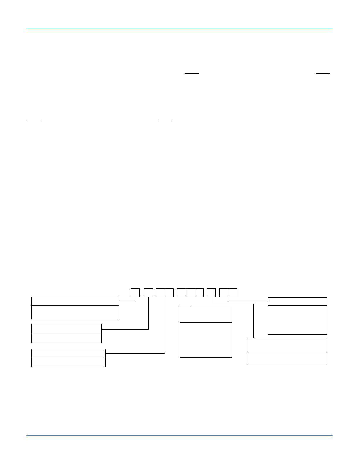
TABLE OF CONTENTS
360101-XTG-B-0508
DESCRIPTION . . . . . . . . . . . . . . . . . . . . . . . . . . . . . . . . . . .1
STANDARD FEATURES / BENEFITS. . . . . . . . . . . . . . . . .1
FIELD-INSTALLED ACCESSORIES . . . . . . . . . . . . . . . . . .3
TYPICAL APPLICATIONS . . . . . . . . . . . . . . . . . . . . . . . . .16
MECHANICAL SPECIFICATIONS. . . . . . . . . . . . . . . . . . .21
LIST OF FIGURES
Fig. # Pg. #
1 UNIT CUTAWAY . . . . . . . . . . . . . . . . . . . . . . . . . . . . . . .4
2 TYPICAL FIELD WIRING DIAGRAM . . . . . . . . . . . . . 11
3 UNIT DIMENSIONS . . . . . . . . . . . . . . . . . . . . . . . . . . 14
4 CENTER OF GRAVITY. . . . . . . . . . . . . . . . . . . . . . . . 15
5 TYPICAL SLAB ON GROUND INSTALLATION. . . . . 16
6 TYPICAL ROOF CURB INSTALLATION . . . . . . . . . . 16
7 ROOF CURB DIMENSIONS (8” ROOF CURB ALSO
AVAILABLE) . . . . . . . . . . . . . . . . . . . . . . . . . . . . . . . . .17
8 ROOF CURB APPLICATION . . . . . . . . . . . . . . . . . . . 17
9 TYPICAL WIRING DIAGRAM (208/230-1-60 POWER
SUPPLY) DEB MODELS . . . . . . . . . . . . . . . . . . . . . . .18
10 TYPICAL WIRING DIAGRAM (208/230-3-60 POWER
SUPPLY) DEB MODELS . . . . . . . . . . . . . . . . . . . . . . .19
11 TYPICAL WIRING DIAGRAM (460-3-60 AND 575-3-60
POWER SUPPLY) DEB MODELS . . . . . . . . . . . . . . . .20
LIST OF TABLES
Tbl. # Pg. #
1 PHYSICAL DATA . . . . . . . . . . . . . . . . . . . . . . . . . . . . . . 5
2 RATINGS - ARI . . . . . . . . . . . . . . . . . . . . . . . . . . . . . . . .5
3 COOLING CAPACITIES - 2-1/2 TON (DEB030) . . . . . . 6
4 COOLING CAPACITIES - 3 TON (DEB036) . . . . . . . . . 7
5 COOLING CAPACITIES - 3-1/2 TON (DEB042) . . . . . . 8
6 COOLING CAPACITIES - 4 TON (DEB048) . . . . . . . . . 9
7 COOLING CAPACITIES - 5 TON (DEB060) . . . . . . . .10
8 SIDE AND BOTTOM SUPPLY AIR BLOWER
PERFORMANCE . . . . . . . . . . . . . . . . . . . . . . . . . . . . .11
9 ADDITIONAL STATIC RESISTANCE . . . . . . . . . . . . . 11
10 ELECTRICAL DATA . . . . . . . . . . . . . . . . . . . . . . . . . . .12
11 ELECTRICAL DATA (COOLING/ELECTRIC HEAT) . . 12
12 UNIT WEIGHTS . . . . . . . . . . . . . . . . . . . . . . . . . . . . . .15
D
2 E B A
PRODUCT CATEGORY
D = Single Package Air Conditioner
(Air Cooled)
PRODUCT GENERATION
2 = 2nd Generation
PRODUCT IDENTIFIER
EB = 10 SEER Cooling Models
2 Johnson Controls Unitary Products
20 4 0 6
NOMINAL COOLING
CAPACITY (MBH)
030 = 30,000 BTUH
036 = 36,000 BTUH
042 = 42,000 BTUH
048 = 48,000 BTUH
060 = 60,000 BTUH
VOLTAGE CODE
06 = 208/230-1-60
25 = 208/230-3-60
46 = 460-3-60
58 = 575-3-60
FACTORY
INSTALLED ELECTRIC HEAT
A = No Electric Heat Installed
Page 3

360101-XTG-B-0508
STANDARD FEATURES/BENEFITS (CONT.)
UTILITY CONNECTIONS MADE EASY - Electrical utility
knockouts are provided through the bottom as well as the side
of the unit. Utility connections can be made quickly and with a
minimum amount of field labor. A field supplied and field
installed electrical disconnect switch must be installed.
CONVERTIBLE AIRFLOW DESIGN - The bottom duct
openings are covered when they leave the factory ready to be
used for a side supply / side return application. If a bottom supply
/ bottom return application is desired, you simply remove the tw o
panels from the bottom of the unit and place them in the side
supply / side return duct openings. No panel cutting is required
and no accessory panel is necessary. Convertible airflow design
allows maximum field flexibility and minimum inventory.
CONDENSATE PAN - A non-corrosive, long-lasting, water-tight
pan is positioned below the evaporator coil to collect and drain
all condensate. Less collection of stagnate condensate will
build-up. The condensate pan conforms to ASHRAE 62-89
standards (Ventilation for Acceptable Indoor Air Quality).
CONDENSATE DRAIN - The heavy duty, 3/4 inch NPTI copper
connection is more tolerable during installation and is more
durable over time. The connection is rigidly mounted to assure
proper fit and leak tight seal.
DURABLE FINISH - With a heavy duty cabinet made of powderpainted, galvanized steel the neutral color blends into
surrounding areas. The powered paint, provides a better paint to
steel bond, which resists corrosion and rust creep. The special
primer formulas and glossy earth tone finish insure less fading
when exposed to sunlight and offers a more attractive on site
appearance. This paint finish exceeds ASTM-B117 standards for
1000 hours salt spray rating, the highest in the industry.
FULL PERIMETER BASE RAILS - The easily removable base
rails provide a solid foundation for the entire unit and protects
the unit during shipment. The rails provide fork lift access from
all sides, and rigging holes are also provided so that an
overhead crane can be used to place the units on a roof. On
applications when the unit is placed on a pad, the base will
keep the unit off the pad to deter corrosion. On applications
where height is limited, the 2-3/8 inch high base rails may be
removed on location.
MORE ATTRACTIVE APPEARANCE - A single piece “Water
Shed” top cover containing a top discharge condenser fan
arrangement requires less square footage on installation and
provides a wider variety of installations. The one piece design
adds greater water integrity. Rounded corners with water drip
edges add to the attractive appearance. The cabinet panels
have a non-fibrous insulation that does not add insulation fibers
into conditioned area.
CONDENSER COIL GRILLE - A multi-piece totally enclosed,
rigidly mounted condenser coil grille provides protection from
objects and personal after installation and provides protection
during transit and installation.
LOW OPERATING SOUND LEVEL - The upward air flow carries
the normal operating noise up and away from the living area. The
rigid top panel effectively isolates any motor sound. Isolator
mounted compressor and the rippled fins of the condenser coil
muffle the normal fan motor and compressor operating sounds.
The unique formed base pan also aids in sound alterations with it's
“Super-Structure” design. This design strategically places
embossments in the pan for optimum strength and rigidity.
FAN SYSTEM - All models operate over a wide range of design
conditions with a 3-speed direct-drive fan motor. These units
easily match all types of applications and provides greater on
site flexibility to match comfort requirement.
SIMPLE CONTROL CIRCUIT - A low voltage printed circuit
board contains a low voltage terminal strip. The electrical
control box is not located in the compressor compartment. All
wiring internal to the unit is color/number coded.
PROTECTED COMPRESSOR - The compressor is internally
protected against high pressure and temperature. This is
accomplished by the simultaneous operation of high pressure
relief valve and a temperature sensor which protect the
compressor if undesirable operating conditions occur.
EXCLUSIVE COIL DESIGN - Grooved copper tubes and
enhanced aluminum fin construction improves heat transfer for
maximum efficiency and durability.
LOW MAINTENANCE - Long life, permanently lubricated
condenser and evaporator fan motor bearings need no annual
maintenance adding greater reliability to the unit. Blower
assembly can be easily removed for cleaning by the unique
“Slip- Track” slide-out blower assembly.
SECURED SERVICE ACCESS PORTS - Protected, externally
mounted, re-usable service access ports are provided on both
the high and low lines for ease of evacuating and charging the
system. No final field mounting required.
EASY SERVICE ACCESS - A large, single panel covers the
electrical controls and makes servicing easy. The blower
compartment has an additional large panel with a built-in
handle tab. Removing this panel will allow the blower assembly
to slide-out for easy removal for maintenance and ease of
trouble shooting.
REPLACEMENT PARTS - The installer has no need to carry
an inventory of unique parts or needs special training to replace
any of the components parts for these units. All are easily
obtained from Source 1 or other part houses.
TOP DISCHARGE - The top discharge condenser fan does not
disrupt neighboring areas and does not dry-out vegetation
surrounding the unit. The warm air from the top mounted fan is
blown up away from the structure and any landscaping. This
allows compact location on multi-unit applications.
Johnson Controls Unitary Products 3
FIELD-INSTALLED ACCESSORIES
ECONOMIZER DOWN DISCHARGE / SUPPLY KIT -
Modulating integrated economizer provides simultaneous
operation between the mechanical cooling and economizer
Page 4

360101-XTG-B-0508
operation. Independent blade design insures proper control and
less than 1% leak rate. Includes hood and mesh bird screen
filter integrated into the hood, dry bulb sensor and relief
damper. Separate field accessories of single enthalpy and dual
enthalpy are also available.
SINGLE ENTHALPY SENSOR - Sensor replaces dry bulb
sensor standard in economizer kit. Provides improved
economizer operation by sensing the dry bulb temperature from
outdoors plus the enthalpy content of the outdoor air.
DUAL ENTHALPY SENSOR - Additional sensor to single
enthalpy sensor. Sensor senses both the return air temperature
dry bulb and humidity in conjunction with the single enthalpy to
determine the most economical mix. Single Enthalpy sensor
also required.
UPGRADE SAFETY PACKAGE - Contains screw-in type High
pressure, Low Pressure/Loss of Charge switch, freeze protection
switch and lockout relay. Switches are placed onto existing
schrader ports located in the unit by furnished adapters. When
abnormal conditions are sensed through the pressure switches,
the unit will lock out preventing any further operation until reset or
problem is corrected. Package agency approved.
HAIL GUARD KIT - Kit contains protected grilles made of
expanded aluminum grilles with full perimeter inch frame.
Sloped hoods are also included to assure maximum protection..
ANTI SHORT CYCLE TIMER - Automatically prevents the
compressor from restarting for 5 minutes after cycled off. Not
required if Thermostat 2ET07700224 and 2ET04700224 are
used.
FILTER / FRAME KIT (Single Phase only) - Kit contains the
necessary hardware to field install return air filters into the base
unit. Pre-cut filter racks and appropriate cleanable standard
size filters are shipped in one kit. (1" filter is supplied) This kit is
available for single phase horizontal or vertical duct application
only. Standard in all 3 Phase models.
MOTORIZED FRESH AIR DAMPER - Designed for duct
mounted side return and unit mounted down shot return
applications. Damper capable of providing 0% thru 50% of
outdoor air (field supplied). Closes on power loss, includes
hood and screen assembly.
RECTANGLE TO ROUND ADAPTERS - Kit includes one
supply and one return air rectangle to round duct adapter.
Adapters are preformed and designed to fit over current duct
openings on the base unit. Transition is from 15” square to 14”
round.
ROOF CURBS - NRCA approved curbs provide proper fit to
base unit for rooftop installations. Curbs are designed to be
assembled through hinge pins in each corner. Kit also provides
seal strip to assure a water tight seal. Eight and 14 inch high
roof curbs are available.
MANUAL OUTDOOR DAMPER - Provides 0% thru 50%
outdoor air capability (field adjustable). Designed for duct
mounted side return and unit mounted down shot return
applications. Includes hood and screen assembly.
WALL THERMOSTAT - The units are designed to operate with
24-volt electronic and electro-mechanical thermostats. All units
can operate with single stage heat / single stage cool
thermostats - with or without the economizer.
LOW AMBIENT KIT - Kit provides necessary hardware to
convert unit to operate in cooling cycle down to 0 °F. Standard
unit operation 45 °F.
TRANSFORMER KIT - Kit provides necessary hardware to
provide single phase models from factory furnished 40 VA
transformer capability to 75 VA transformer capability.
ELECTRIC HEATERS - Each heater package provides easy
installation of electric heat strips. Slide in design with plug in
harness and agency approved. Heaters are available from 5.0
KW sizes and are designed for single point connection.
DIRECT DRIVE
CONDENSER
FAN MOTOR
HIGHLY EFFICIENT ENHANCED
BACK AND BOTTOM
RETURN AIR
AND SUPPLY AIR
DUCT OPENING
HIGH VOLTAGE
TERMINAL BLOCK
LOW VOLTAGE
TERMINAL BLOCK
LONG LASTING
POWDER PAINT
FINISH EARTH
TONE COLOR
HIGH EFFICIENCY
COMPRESSOR
RIGIDLY
MOUNTED
COPPER TUBE/ALUMINUM FIN
EVAPORATOR COIL
HIGHLY EFFICIENT
ENHANCED COPPER
TUBE/ALUMINUM FIN
CONDENSER COIL
DECORATIVE
PROTECTIVE
COIL GUARD
3-SPEED DIRECT DRIVE
BLOWER MOTOR WITH
SLIDE-OUT BLOWER ASSEMBLY
HEAVY GAUGE
REMOVABLE
BASE RAILS
FIGURE 1 - UNIT CUTAWAY
4 Johnson Controls Unitary Products
Page 5

360101-XTG-B-0508
T A BLE 1: PHYSICAL DATA
DEB
3
4
3
4
EVAPORATOR
BLOWER
MODELS
CENTRIFUGAL BLOWER (Dia. x Wd. in.) 10 X 8 10 x 8 11 X 10 11 x 10 11 x 10
FAN MOTOR HP ½ 1
030 036 042 048 060
3
4
ROWS DEEP 22223
EVAPORATOR
COIL
FINS PER INCH 15 15 15 13 16
FACE AREA (Sq. Ft.) 4.38 4.38 4.38 5.62 5.26
PROPELLER DIA. (in.) 22 22 22 22 22
CONDENSER
FAN
FAN MOTOR HP 1/4 1/4 1/4 1/4 1/4
NOM. CFM TOTAL 2,400 2,400 2,400 2,800 2,800
ROWS DEEP 11111
CONDENSER
COIL
FINS PER INCH 20 18 16 13 20
FACE AREA (Sq. Ft.) 8.3 8.3 11.7 16.4 16.4
CHARGE REFRIGERANT 22 (lbs./oz.) 3 / 13 3 / 10 4 / 8 5 / 15 5 /15
FILTER FACE AREA (Sq. Ft.) / Qty. / Size 2.14 / 2 / 14" x 22"
COMPRESSOR HERMETIC, QTY. = 1 (Type) Recip. Recip. Recip. Scroll Scroll
T ABLE 2: RATINGS - ARI
Model DEB
Cooling Capacity
1
80/67-95 °F Sound Rating
(decibels)
2
Electric Heat
Nom. Capacity
KW
(single phase)
030 29.0 8.9 79 5.0, 7.5, 10.0, 15.0 036 35.2 8.7 81 5.0, 7.5, 10.0, 15.0 10.0, 15.0
042 40.5 9.4 83 5.0, 7.5, 10.0, 15.0 10.0, 15.0
048 46.5 8.8 81 10.0, 15.0, 20.0, 25.0 10.0, 15.0, 20.0, 25.0
060 59.0 8.8 79 10.0, 15.0, 20.0, 25.0 10.0, 15.0, 20.0, 25.0
1. Certified in accordance with the Unitary Small Equipment certification program, which is based on ARI Standard 210/
240.
2. Rated in accordance with ARI Standard 270.
EER = Energy Efficiency Ratio - the total cooling output in BTU's during a normal annual usage period for cooling divided by the total electric
power input in watt-hours during the same period.
Electric Heat
Nom. Capacity
KW
(three phase)MBH EER
Johnson Controls Unitary Products 5
Page 6
T ABLE 3: COOLING CAPACITIES - 2-1/2 TON (DEB030)
TEMPERATURE
OF AIR ON
OUTDOOR COIL
Net Cap
MBH
Total Power
Input kW
85 °F
95 °F
105 °F
115 °F
125 °F
1. These are net capacity ratings. The indoor blower motor heat has already been subtracted from the gross cooling capacity
1
MBH
Sensible Capacity
Total Power
1
MBH
Sensible Capacity
Total Power
1
MBH
Sensible Capacity
Total Power
1
MBH
Sensible Capacity
Total Power
1
MBH
Sensible Capacity
Net Cap
MBH
Input kW
Net Cap
MBH
Input kW
Net Cap
MBH
Input kW
Net Cap
MBH
Input kW
86 18.2 23.6 27.5 28.1 20.1 25.8 27.8 28.4 21.9 28.0 28.1 28.7 23.3 29.6 28.4 29.1 24.8 31.3 28.8 29.5
83 16.1 21.4 25.5 26.3 17.5 23.3 26.8 27.5 19.0 25.1
80 14.0 19.3 23.3 24.1 15.0 20.7 25.1 25.9 16.0 22.2 26.8 27.7 16.7 23.1 27.8 28.6 17.3 24.0
77 11.8 17.2 21.2 22.0 12.5 18.2 22.5 23.4 13.1 19.3 23.9 24.8 13.4 19.7 24.5 25.3 13.6 20.2 25.1 25.8
74 9.7 15.0 19.1 19.9 10.0 15.7 20.0 20.9 10.2 16.3 21.0 21.9 10.1 16.4 21.2 22.0 9.9 16.5 21.4 22.1
Bulb °F
Entering Dry
71 - 12.9 16.9 17.7 - 13.2 17.5 18.3 - 13.4 18.0 19.0 - 13.1 17.9 18.7 - 12.8 17.7 18.4
68 - 10.8 14.8 15.6 - 10.6 15.0 15.8 - 10.5 15.1 16.1 - 9.8 14.5 15.3 - 9.1 13.9 14.6
86 17.5 22.2 24.4 24.8 19.5 24.7 25.3 25.7 21.6 27.2 26.2 26.7 23.1 28.1 25.9 26.4 24.6 28.9 25.6 26.0
83 15.4 20.1 24.1 23.9 17.0 22.2 25.2 25.3 18.7 24.3
80 13.2 18.0 22.0 21.8 14.5 19.7 24.1 23.8 15.8 21.4
77 11.1 15.8 19.9 19.6 12.0 17.2 21.6 21.3 12.8 18.5 23.3 23.0 13.1 19.0 22.6 22.6 13.4 19.6 21.8 22.3
74 9.0 13.7 17.7 17.5 9.4 14.6 19.1 18.8 9.9 15.6 20.4 20.1 9.8 15.7 19.2 19.3 9.7 15.9 18.1 18.6
Bulb °F
Entering Dry
71 - 11.6 15.6 15.3 - 12.1 16.5 16.3 - 12.7 17.5 17.2 - 12.4 15.9 16.0 - 12.1 14.4 14.8
68 - 9.4 13.5 13.2 - 9.6 14.0 13.7 - 9.7 14.6 14.3 - 9.1 12.6 12.7 - 8.4 10.6 11.1
86 16.5 21.3 22.2 22.3 18.5 23.4 23.1 23.2 20.5 25.6 24.0 24.1 22.0 25.9 23.7 23.9 23.5 26.3 23.5 23.6
83 14.4 19.2 22.0 21.8 16.0 21.2 23.0 22.9 17.6 23.3
80 12.3 17.0 19.8 19.6 13.5 18.7 21.8 21.6 14.7 20.4 23.8 23.5 15.4 21.3 23.6 23.6 16.0 22.2
77 10.1 14.9 17.7 17.5 10.9 16.2 19.3 19.0 11.8 17.5 20.9 20.6 12.0 18.0 20.3 20.3 12.3 18.5 19.8 19.9
74 8.0 12.7 15.6 15.3 8.4 13.7 16.8 16.5 8.9 14.6 17.9 17.7 8.7 14.7 17.0 16.9 8.6 14.8 16.0 16.2
Bulb °F
Entering Dry
71 - 10.6 13.4 13.2 - 11.1 14.2 14.0 - 11.7 15.0 14.8 - 11.4 13.7 13.6 - 11.0 12.3 12.5
68 - 8.5 11.3 11.1 - 8.6 11.7 11.5 - 8.7 12.1 11.9 - 8.0 10.3 10.3 - 7.3 8.6 8.7
86 15.6 20.3 20.0 19.8 17.5 22.1 20.8 20.7 19.5 23.9 21.7 21.5 20.9 23.7 21.6 21.4 22.3 23.6 21.4 21.3
83 13.4 18.2 19.8 19.6 15.0 20.3 20.7 20.6 16.5 22.3
80 11.3 16.1 17.7 17.5 12.5 17.7 19.5 19.3 13.6 19.4 21.3 21.1 14.2 20.3 21.4 21.2 14.9 21.1
77 9.1 13.9 15.5 15.3 9.9 15.2 17.0 16.8 10.7 16.5 18.4 18.2 10.9 16.9 18.1 17.9 11.1 17.4 17.7 17.6
74 7.0 11.8 13.4 13.2 7.4 12.7 14.4 14.2 7.8 13.6 15.5 15.3 7.6 13.6 14.7 14.6 7.4 13.7 14.0 13.8
Bulb °F
Entering Dry
71 - 9.6 11.2 11.1 - 10.1 11.9 11.7 - 10.6 12.6 12.4 - 10.3 11.4 11.2 - 10.0 10.2 10.1
68 - 7.5 9.1 8.9 - 7.6 9.4 9.2 - 7.7 9.7 9.5 - 7.0 8.1 7.9 - 6.2 6.5 6.4
86 14.6 19.4 17.8 17.4 16.5 20.8 18.6 18.2 18.4 22.2 19.4 19.0 19.8 21.6 19.4 18.9 21.2 20.9 19.4 18.9
83 12.5 17.2 17.6 17.5 14.0 19.3 18.5
80 10.3 15.1 15.5 15.3 11.4 16.7 17.2 17.0 12.6 18.4 18.9 18.7 13.1 19.2 19.1 18.8 13.7 20.1
77 8.2 13.0 13.3 13.2 8.9 14.2 14.7 14.5 9.6 15.5 16.0 15.8 9.8 15.9 15.8 15.5 10.0 16.3 15.6 15.2
74 6.0 10.8 11.2 11.1 6.4 11.7 12.1 12.0 6.7 12.6 13.1 12.9 6.5 12.6 12.5 12.2 6.3 12.6 11.9 11.5
Bulb °F
Entering Dry
71 - 8.7 9.1 8.9 - 9.2 9.6 9.4 - 9.6 10.1 10.0 - 9.3 9.2 8.9 - 8.9 8.2 7.7
68 - 6.5 6.9 6.8 - 6.6 7.1 6.9 - 6.7 7.2 7.0 - 5.9 5.8 5.5 - 5.2 4.5 4.0
750 CFM 875 CFM 1,000 CFM 1,125 CFM 1,250 CFM
WB °F WB °F WB °F WB °F WB °F
72 67 62 57 72 67 62 57 72 67 62 57 72 67 62 57 72 67 62 57
32.3 29.8 27.5 28.1 32.6 30.1 27.8 28.4 33.0 30.4 28.1 28.7 33.5 30.9 28.4 29.1 33.9 31.3 28.8 29.5
2.94 2.92 2.83 2.81 3.02 3.00 2.90 2.88 3.10 3.08 2.98 2.96 3.20 3.18 3.08 3.06 3.31 3.28 3.18 3.16
29.1 27.5 24.4 24.8 30.2 28.6 25.3 25.7 31.3 29.7 26.2 26.7 30.9 29.3 25.9 26.4 30.5 28.9 25.6 26.0
3.17 3.11 3.04 3.03 3.24 3.17 3.10 3.09 3.30 3.23 3.16 3.15 3.43 3.36 3.29 3.27 3.56 3.49 3.41 3.39
26.7 24.8 22.2 22.3 27.8 25.8 23.1 23.2 28.9 26.8 24.0 24.1 28.6 26.5 23.7 23.9 28.3 26.3 23.5 23.6
3.38 3.28 3.22 3.22 3.45 3.35 3.29 3.28 3.52 3.42 3.36 3.35 3.66 3.55 3.49 3.48 3.79 3.68 3.62 3.61
24.3 22.0 20.0 19.8 25.4 22.9 20.8 20.7 26.4 23.9 21.7 21.5 26.2 23.7 21.6 21.4 26.1 23.6 21.4 21.3
3.58 3.45 3.41 3.41 3.66 3.52 3.48 3.48 3.74 3.60 3.56 3.56 3.89 3.74 3.69 3.69 4.03 3.87 3.83 3.83
21.9 19.2 17.8 17.4 22.9 20.1 18.6 18.2 23.9 21.0 19.4 19.0 23.9 21.0 19.4 18.9 23.9 20.9 19.4 18.9
3.8 3.6 3.6 3.6 3.9 3.7 3.7 3.7 4.0 3.8 3.8 3.8 4.1 3.9 3.9 3.9 4.3 4.1 4.0 4.0
ALL SENSIBLE CAPACITIES
AIR ON INDOOR COIL
28.1 28.7 20.0 26.4 28.4 29.1 21.1 27.7 28.8 29.5
26.2 26.7 19.8 25.7 25.9 26.4 20.9 27.0 25.6 26.0
26.2 25.9 16.5 22.4 25.9 26.0 17.2 23.3 25.6 26.0
24.0 24.1 18.7 24.3 23.7 23.9 19.7 25.3 23.5 23.6
21.7 21.5 17.6 23.0 21.6 21.4 18.6 23.6 21.4 21.3
18.2 15.5 21.3 19.4 19.0 16.5 21.6 19.4 18.9 17.4 21.9 19.4 18.9
360101-XTG-B-0508
28.8 29.5
23.5 23.6
21.4 21.3
19.4 18.9
6 Johnson Controls Unitary Products
Page 7
360101-XTG-B-0508
T ABLE 4: COOLING CAPACITIES - 3 TON (DEB036)
TEMPERATURE
OF AIR ON
OUTDOOR COIL
Net Cap
MBH
Total Power
Input kW
85 °F
95 °F
105 °F
115 °F
125 °F
1. These are net capacity ratings. The indoor blower motor heat has already been subtracted from the gross cooling capacity
1
MBH
Sensible Capacity
Total Power
1
MBH
Sensible Capacity
Total Power
1
MBH
Sensible Capacity
Total Power
1
MBH
Sensible Capacity
Total Power
1
MBH
Sensible Capacity
Net Cap
MBH
Input kW
Net Cap
MBH
Input kW
Net Cap
MBH
Input kW
Net Cap
MBH
Input kW
86 19.7 25.4 28.5 28.4 22.2 28.5 30.3 30.1 24.6 31.5 32.1 31.9 26.3 33.5 32.7 32.6 28.0 35.5 33.4 33.2
83 17.2 22.9 26.7
80 14.6 20.3 24.2 26.0 16.1 22.4 26.7 28.7 17.6 24.5 29.2 31.4 18.4 25.6 30.4 32.3 19.1 26.6 31.6
77 12.0 17.7 21.6 23.4 13.1 19.4 23.7 25.6 14.1 21.0 25.7 27.9 14.4 21.6 26.4 28.3 14.6 22.1 27.2 28.8
74 9.5 15.2 19.1 20.8 10.1 16.4 20.6 22.6 10.6 17.5 22.2 24.4 10.4 17.6 22.5 24.3 10.2 17.6 22.7 24.3
Bulb °F
Entering Dry
71 - 12.6 16.5 18.3 - 13.3 17.6 19.6 - 14.1 18.7 20.9 - 13.6 18.5 20.4 - 13.2 18.2 19.8
68 - 10.0 13.9 15.7 - 10.3 14.6 16.5 - 10.6 15.2 17.4 - 9.6 14.5 16.4 - 8.7 13.7 15.4
86 18.5 24.3 27.8 26.8 21.0 27.4 29.4 28.4 23.4 30.5 31.0 29.9 24.8 32.0 31.8 30.7 26.1 33.4 32.6 31.5
83 16.0 21.7 25.7 26.6 18.0 24.4 28.4 28.2 19.9 27.0
80 13.4 19.2 23.2 24.0 14.9 21.3 25.8 26.7 16.4 23.5 28.4 29.4 16.8 24.0 29.0 30.0 17.1 24.5 29.6 30.7
77 10.8 16.6 20.6 21.4 11.9 18.3 22.8 23.7 12.9 20.0 24.9 25.9 12.8 20.0 25.0 26.1 12.7 20.0 25.1 26.2
74 8.3 14.0 18.0 18.9 8.9 15.3 19.7 20.6 9.4 16.5 21.4 22.4 8.8 16.0 21.0 22.1 8.2 15.5 20.7 21.7
Bulb °F
Entering Dry
71 - 11.5 15.5 16.3 - 12.2 16.7 17.6 - 13.0 17.9 18.9 - 12.0 17.1 18.1 - 11.1 16.2 17.3
68 - 8.9 12.9 13.7 - 9.2 13.7 14.6 - 9.5 14.4 15.4 - 8.1 13.1 14.1 - 6.6 11.7 12.8
86 17.5 23.3 25.0 24.4 19.9 26.3 26.6 26.0 22.3 29.2 28.2 27.6 23.6 30.3 28.9 28.3 24.8 31.4 29.6 29.0
83 15.0 20.7 24.0 24.3 16.9 23.3 26.1 25.9 18.8 25.9
80 12.4 18.1 21.4 21.7 13.9 20.3 23.9 24.3 15.3 22.4 26.5 26.8 15.6 22.8 26.9 27.3 15.8 23.1 27.3 27.7
77 9.8 15.6 18.8 19.1 10.8 17.3 20.9 21.2 11.8 18.9 23.0 23.3 11.6 18.8 22.9 23.3 11.4 18.7 22.8 23.2
74 7.3 13.0 16.3 16.6 7.8 14.2 17.9 18.2 8.3 15.4 19.5 19.8 7.6 14.8 18.9 19.3 6.9 14.2 18.4 18.8
Bulb °F
Entering Dry
71 - 10.4 13.7 14.0 - 11.2 14.8 15.2 - 11.9 16.0 16.3 - 10.8 14.9 15.3 - 9.7 13.9 14.3
68 - 7.9 11.1 11.4 - 8.2 11.8 12.1 - 8.4 12.5 12.8 - 6.9 10.9 11.3 - 5.3 9.4 9.8
86 16.5 22.2 22.2 22.0 18.9 25.1 23.8 23.6 21.2 28.0 25.5 25.2 22.4 28.6 26.1 25.8 23.5 29.3 26.7 26.4
83 14.0 19.7
80 11.4 17.1 19.6 19.4 12.8 19.2 22.1 21.8 14.2 21.4 24.5 24.3 14.4 21.6 24.8 24.5 14.5 21.8 25.0 24.7
77 8.8 14.5 17.1 16.9 9.8 16.2 19.0 18.8 10.7 17.9 21.0 20.8 10.4 17.6 20.8 20.5 10.1 17.3 20.5 20.3
74 6.3 12.0 14.5 14.3 6.8 13.2 16.0 15.8 7.2 14.4 17.5 17.3 6.4 13.6 16.8 16.5 5.6 12.9 16.1 15.8
Bulb °F
Entering Dry
71 - 9.4 11.9 11.7 - 10.1 13.0 12.7 - 10.9 14.0 13.8 - 9.6 12.8 12.5 - 8.4 11.6 11.3
68 - 6.8 9.4 9.2 - 7.1 9.9 9.7 - 7.4 10.5 10.3 - 5.6 8.8 8.6 - 3.9 7.1 6.9
86 15.5 21.2 19.4 19.6 17.8 24.0 21.1 21.3 20.1 26.7 22.7 22.9 21.2 27.0 23.2 23.4 22.2 27.2 23.7 23.9
83 13.0 18.6 20.4 19.7 14.8 21.2 21.6
80 10.4 16.1 17.9 17.1 11.8 18.2 20.2 19.4 13.1 20.3 22.6 21.7 13.2 20.4 22.6 21.7 13.2 20.4 22.7 21.8
77 7.8 13.5 15.3 14.6 8.7 15.2 17.2 16.4 9.6 16.8 19.1 18.2 9.2 16.4 18.7 17.7 8.8 16.0 18.2 17.3
74 5.3 10.9 12.7 12.0 5.7 12.1 14.2 13.3 6.1 13.3 15.6 14.7 5.2 12.4 14.7 13.8 4.3 11.5 13.8 12.8
Bulb °F
Entering Dry
71 - 8.4 10.2 9.4 - 9.1 11.1 10.3 - 9.8 12.1 11.2 - 8.4 10.7 9.8 - 7.0 9.3 8.4
68 - 5.8 7.6 6.9 - 6.1 8.1 7.3 - 6.3 8.6 7.7 - 4.4 6.7 5.8 - 2.6 4.8 3.9
900 CFM 1,050 1,200 1,350 1,500
WB °F WB °F WB °F WB °F WB °F
72 67 62 57 72 67 62 57 72 67 62 57 72 67 62 57 72 67 62 57
34.7 32.3 28.5 28.4 36.9 34.3 30.3 30.1 39.0 36.4 32.1 31.9 39.9 37.1 32.7 32.6 40.7 37.9 33.4 33.2
3.61 3.52 3.46 3.46 3.62 3.53 3.47 3.47 3.63 3.55 3.48 3.48 3.70 3.61 3.55 3.55 3.77 3.68 3.61 3.61
28.4 19.2 25.5 29.4 30.1 21.1 28.0 32.1 31.9 22.4 29.5 32.7 32.6 23.6 31.0 33.4 33.2
32.5 30.4 27.8 26.8 34.4 32.2 29.4 28.4 36.3 34.0 31.0 29.9 37.2 34.8 31.8 30.7 38.1 35.7 32.6 31.5
3.85 3.74 3.70 3.68 3.85 3.75 3.71 3.68 3.86 3.75 3.71 3.69 3.93 3.82 3.78 3.76 4.01 3.90 3.86 3.83
29.5 27.4 25.0 24.4 31.4 29.2 26.6 26.0 33.3 31.0 28.2 27.6 34.1 31.7 28.9 28.3 35.0 32.5 29.6 29.0
4.05 3.92 3.93 3.85 4.07 3.94 3.95 3.87 4.09 3.96 3.97 3.89 4.15 4.02 4.02 3.95 4.21 4.08 4.08 4.00
26.5 24.4 22.2 22.0 28.4 26.2 23.8 23.6 30.4 28.0 25.5 25.2 31.1 28.6 26.1 25.8 31.8 29.3 26.7 26.4
4.25 4.11 4.16 4.03 4.28 4.14 4.19 4.06 4.31 4.17 4.22 4.09 4.36 4.21 4.27 4.13 4.40 4.25 4.31 4.17
22.2 22.0 15.9 22.3 23.8 23.6 17.7 24.9 25.5 25.2 18.4 25.6 26.1 25.8 19.0 26.3 26.7 26.4
23.5 21.4 19.4 19.6 25.4 23.2 21.1 21.3 27.4 25.0 22.7 22.9 28.0 25.5 23.2 23.4 28.6 26.1 23.7 23.9
4.5 4.3 4.4 4.2 4.5 4.3 4.4 4.2 4.5 4.4 4.5 4.3 4.6 4.4 4.5 4.3 4.6 4.4 4.5 4.3
ALL SENSIBLE CAPACITIES
AIR ON INDOOR COIL
31.0 29.9 20.8 28.0 31.8 30.7 21.6 29.0 32.6 31.5
28.2 27.6 19.6 26.8 28.9 28.3 20.3 27.6 29.6 29.0
21.3 16.6 23.8 22.7 22.9 17.2 24.4 23.2 23.4 17.7 24.9 23.7 23.9
33.2
Johnson Controls Unitary Products 7
Page 8
T ABLE 5: COOLING CAPACITIES - 3-1/2 TON (DEB042)
TEMPERATURE
OF AIR ON
OUTDOOR COIL
Net Cap
MBH
Total Power
Input kW
85 °F
95 °F
105 °F
115 °F
125 °F
1. These are net capacity ratings. The indoor blower motor heat has already been subtracted from the gross cooling capacity
1
MBH
Sensible Capacity
Total Power
1
MBH
Sensible Capacity
Total Power
1
MBH
Sensible Capacity
Total Power
1
MBH
Sensible Capacity
Total Power
1
MBH
Sensible Capacity
Net Cap
MBH
Input kW
Net Cap
MBH
Input kW
Net Cap
MBH
Input kW
Net Cap
MBH
Input kW
86 23.8 31.3 36.5 34.1 26.1 34.2 37.7 35.2 28.5 37.0 38.8 36.3 30.5 39.4 39.3 36.8 32.6 41.9 39.8 37.2
83 20.8 28.3 34.6
80 17.8 25.4 31.6 31.9 19.1 27.1 33.8 34.1 20.3 28.8 36.0
77 14.9 22.4 28.6 28.9 15.5 23.6 30.3 30.6 16.2 24.7 31.9 32.2 16.6 25.5 32.9 32.1 16.9 26.2 34.0 32.0
74 11.9 19.4 25.6 26.0 12.0 20.0 26.7 27.0 12.1 20.7 27.8 28.1 11.9 20.8 28.3 27.5 11.7 21.0 28.8 26.8
Bulb °F
Entering Dry
71 - 16.4 22.7 23.0 - 16.5 23.2 23.5 - 16.6 23.7 24.1 - 16.2 23.6 22.8 - 15.8 23.6 21.6
68 - 13.4 19.7 20.0 - 12.9 19.6 20.0 - 12.5 19.6 20.0 - 11.5 19.0 18.2 - 10.6 18.3 16.4
86 23.0 30.4 34.0 32.7 25.4 33.3 35.2 33.9 27.8 36.3 36.5 35.2 29.9 38.3 36.9 35.6 32.0 40.3 37.4 36.0
83 20.0 27.4 33.2
80 17.0 24.4 30.3 30.4 18.3 26.3 32.6 32.8 19.7 28.2 35.0
77 14.0 21.4 27.3 27.5 14.8 22.7 29.1 29.3 15.6 24.1 30.9 31.1 15.9 24.8 31.5 30.9 16.3 25.6 32.1 30.8
74 11.0 18.4 24.3 24.5 11.3 19.2 25.5 25.7 11.5 20.0 26.8 27.0 11.3 20.2 26.9 26.3 11.1 20.4 26.9 25.5
Bulb °F
Entering Dry
71 - 15.4 21.3 21.5 - 15.6 22.0 22.2 - 15.9 22.7 22.9 - 15.5 22.2 21.6 - 15.2 21.7 20.3
68 - 12.4 18.3 18.5 - 12.1 18.4 18.7 - 11.8 18.6 18.8 - 10.9 17.6 17.0 - 10.0 16.5 15.1
86 22.4 29.3 30.8 31.2 24.8 32.1 32.0 32.4 27.3 34.9 33.1 33.6 29.3 36.1 33.5 34.0 31.4 37.3 33.9 34.4
83 19.4 26.3 30.5
80 16.4 23.3 27.8 28.8 17.7 25.3 30.1 31.2 19.1 27.2 32.4
77 13.4 20.3 24.8 25.8 14.2 21.7 26.5 27.6 15.0 23.1 28.3 29.5 15.4 23.9 28.5 29.3 15.8 24.7 28.7 29.1
74 10.4 17.3 21.8 22.8 10.7 18.2 23.0 24.1 10.9 19.0 24.2 25.4 10.7 19.3 23.8 24.7 10.6 19.5 23.5 23.9
Bulb °F
Entering Dry
71 - 14.3 18.8 19.8 - 14.7 19.4 20.6 - 15.0 20.1 21.3 - 14.6 19.2 20.0 - 14.3 18.3 18.7
68 - 11.4 15.8 16.8 - 11.1 15.9 17.0 - 10.9 16.0 17.2 - 10.0 14.5 15.4 - 9.1 13.1 13.5
86 21.7 28.3 27.7 29.8 24.2 30.8 28.8 30.9 26.7 33.4 29.8 32.0 28.8 33.8 30.1 32.3 30.9 34.2 30.5 32.7
83 18.7 25.3
80 15.7 22.3 25.3 27.1 17.1 24.3 27.5 29.5 18.5 26.3
77 12.7 19.3 22.3 24.1 13.6 20.7 24.0 26.0 14.4 22.2 25.7 27.9 14.9 23.0 25.5 27.7 15.3 23.8 25.3 27.5
74 9.7 16.3 19.3 21.1 10.0 17.2 20.4 22.5 10.3 18.1 21.6 23.8 10.2 18.4 20.8 23.0 10.1 18.6 20.1 22.3
Bulb °F
Entering Dry
71 - 13.3 16.3 18.1 - 13.7 16.9 18.9 - 14.0 17.5 19.7 - 13.7 16.2 18.4 - 13.4 14.8 17.1
68 - 10.3 13.3 15.2 - 10.1 13.4 15.4 - 9.9 13.4 15.6 - 9.1 11.5 13.7 - 8.2 9.6 11.9
86 21.1 27.2 24.6 28.3 23.6 29.6 25.5 29.3 26.1 31.9 26.4 30.3 28.3 31.5 26.7 30.7 30.4 31.1 27.1 31.1
83 18.1 24.2 25.0
80 15.1 21.3 22.8 25.5 16.5 23.3 25.0 27.9 17.9 25.3 27.2
77 12.1 18.3 19.8 22.5 13.0 19.7 21.4 24.4 13.9 21.2 23.1 26.3 14.3 22.1 22.5 26.1 14.8 23.0 21.9 25.9
74 9.1 15.3 16.8 19.5 9.4 16.2 17.9 20.8 9.8 17.1 19.0 22.2 9.7 17.4 17.8 21.4 9.5 17.7 16.6 20.7
Bulb °F
Entering Dry
71 - 12.3 13.8 16.5 - 12.7 14.4 17.3 - 13.1 14.9 18.1 - 12.8 13.2 16.8 - 12.5 11.4 15.5
68 - 9.3 10.8 13.5 - 9.1 10.8 13.8 - 9.0 10.8 14.0 - 8.1 8.5 12.1 - 7.3 6.2 10.2
1,050 CFM 1,225 1,400 1,575 1,750
WB °F WB °F WB °F WB °F WB °F
72 67 62 57 72 67 62 57 72 67 62 57 72 67 62 57 72 67 62 57
40.7 39.0 36.5 34.1 42.0 40.3 37.7 35.2 43.3 41.6 38.8 36.3 43.9 42.1 39.3 36.8 44.4 42.6 39.8 37.2
4.09 3.82 3.77 3.75 4.16 3.89 3.83 3.81 4.23 3.95 3.90 3.88 4.38 4.10 4.04 4.02 4.54 4.25 4.18 4.16
34.1 22.6 30.6 36.7 35.2 24.4 32.9 38.8 36.3 25.9 34.8 39.3 36.8 27.3 36.6 39.8 37.2
38.7 36.7 34.0 32.7 40.1 38.1 35.2 33.9 41.6 39.4 36.5 35.2 42.1 39.9 36.9 35.6 42.6 40.3 37.4 36.0
4.16 4.06 3.96 3.98 4.23 4.13 4.03 4.05 4.30 4.19 4.10 4.11 4.44 4.33 4.23 4.25 4.59 4.47 4.37 4.39
32.7 21.9 29.8 34.9 33.9 23.7 32.2 36.5 35.2 25.2 34.1 36.9 35.6 26.7 36.0 37.4 36.0
36.2 33.9 30.8 31.2 37.6 35.1 32.0 32.4 38.9 36.4 33.1 33.6 39.4 36.8 33.5 34.0 39.9 37.3 33.9 34.4
4.40 4.28 4.20 4.22 4.47 4.35 4.27 4.29 4.54 4.42 4.34 4.35 4.69 4.57 4.48 4.50 4.84 4.71 4.63 4.64
31.2 21.3 28.8 31.8 32.4 23.2 31.3 33.1 33.6 24.7 33.2 33.5 34.0 26.2 35.1 33.9 34.4
33.8 31.1 27.7 29.8 35.0 32.2 28.8 30.9 36.3 33.4 29.8 32.0 36.7 33.8 30.1 32.3 37.2 34.2 30.5 32.7
4.64 4.51 4.44 4.46 4.71 4.58 4.51 4.53 4.78 4.65 4.58 4.59 4.94 4.80 4.73 4.75 5.09 4.96 4.88 4.90
27.7 29.8 20.7 27.8 28.8 30.9 22.6 30.3 29.8 32.0 24.2 32.3 30.1 32.3 25.7 34.2 30.5 32.7
31.4 28.3 24.6 28.3 32.5 29.3 25.5 29.3 33.6 30.4 26.4 30.3 34.0 30.7 26.7 30.7 34.5 31.1 27.1 31.1
4.9 4.7 4.7 4.7 4.9 4.8 4.7 4.8 5.0 4.9 4.8 4.8 5.2 5.0 5.0 5.0 5.3 5.2 5.1 5.2
28.3 20.0 26.8 25.7 29.3 22.0 29.4 26.4 30.3 23.6 31.3 26.7 30.7 25.2 33.3 27.1 31.1
ALL SENSIBLE CAPACITIES
AIR ON INDOOR COIL
36.3 21.2 30.1 37.6 36.8 22.1 31.4 39.2 37.2
35.2 20.6 29.5 36.2 35.6 21.5 30.8 37.4 36.0
33.6 20.0 28.6 33.1 34.0 21.0 29.9 33.9 34.4
29.8 32.0 19.5 27.7 30.1 32.3 20.5 29.1 30.5 32.7
30.3 19.0 26.7 27.1 30.7 20.0 28.2 27.1 31.1
360101-XTG-B-0508
8 Johnson Controls Unitary Products
Page 9

360101-XTG-B-0508
T ABLE 6: COOLING CAPACITIES - 4 TON (DEB048)
TEMPERATURE
OF AIR ON
OUTDOOR COIL
Net Cap
MBH
Total Power
Input kW
85 °F
95 °F
105 °F
115 °F
125 °F
1. These are net capacity ratings. The indoor blower motor heat has already been subtracted from the gross cooling capacity
1
MBH
Sensible Capacity
Total Power
1
MBH
Sensible Capacity
Total Power
1
MBH
Sensible Capacity
Total Power
1
MBH
Sensible Capacity
Total Power
1
MBH
Sensible Capacity
Net Cap
MBH
Input kW
Net Cap
MBH
Input kW
Net Cap
MBH
Input kW
Net Cap
MBH
Input kW
86 28.3 35.7 41.3 41.3 31.5 39.6 42.7 42.5 34.7 43.5 44.1 43.7 37.1 46.3 44.7 44.2 39.5 49.1 45.2 44.8
83 24.9 32.3 37.8 39.5 27.4 35.6 41.0 41.6 30.0 38.9
80 21.4 28.9 34.4 36.1 23.4 31.6 37.6 39.4 25.4 34.2 40.7 42.7 26.5 35.7 42.5 43.8 27.6 37.2 44.3
77 18.0 25.5 31.0 32.7 19.4 27.5 33.5 35.4 20.7 29.5 36.1 38.1 21.2 30.4 37.2 38.5 21.6 31.2 38.3 38.9
74 14.6 22.1 27.6 29.3 15.3 23.5 29.5 31.3 16.0 24.9 31.4 33.4 15.8 25.1 31.9 33.1 15.7 25.3 32.4 32.9
Bulb °F
Entering Dry
71 - 18.6 24.2 25.8 - 19.4 25.4 27.3 - 20.2 26.7 28.7 - 19.8 26.6 27.8 - 19.3 26.4 26.9
68 - 15.2 20.7 22.4 - 15.4 21.4 23.2 - 15.5 22.1 24.1 - 14.4 21.3 22.5 - 13.4 20.4 21.0
86 27.7 34.7 39.3 38.8 30.6 38.3 40.5 40.0 33.6 41.9 41.7 41.1 35.3 42.9 40.8 40.2 37.0 44.0 39.9 39.3.
83 24.2 31.3 36.5 37.9 26.6 34.2 39.1 39.5 28.9 37.2
80 20.8 27.9 33.0 34.5 22.5 30.2 35.8 37.4 24.3 32.5 38.5 40.2 24.7 33.0 39.1 39.8 25.0 33.5 39.7
77 17.4 24.5 29.6 31.1 18.5 26.2 31.7 33.3 19.6 27.9 33.9 35.6 19.3 27.7 33.8 34.5 19.1 27.6 33.8 33.3
74 14.0 21.0 26.2 27.7 14.5 22.1 27.7 29.3 14.9 23.2 29.2 30.9 14.0 22.4 28.5 29.1 13.1 21.6 27.8 27.4
Bulb °F
Entering Dry
71 - 17.6 22.8 24.2 - 18.1 23.7 25.2 - 18.5 24.5 26.2 - 17.1 23.2 23.8 - 15.7 21.9 21.4
68 - 14.2 19.4 20.8 - 14.0 19.6 21.2 - 13.9 19.9 21.6 - 11.8 17.9 18.5 - 9.7 15.9 15.5
86 27.0 33.2 37.8 37.4 29.6 36.1 38.3 37.9 32.3 39.1 38.8 38.3 34.3 39.7 38.5 38.0 36.4 40.4 38.2 37.7
83 23.6 29.8 35.7 36.3 25.6 32.2 37.3 37.3 37.6 34.7
80 20.1 26.4 32.3 32.9 21.5 28.2 34.6 35.2 22.9 30.0 36.8 37.5 23.7 31.0 37.5 37.6 24.5 32.0 38.1
77 16.7 22.9 28.9 29.5 17.5 24.2 30.5 31.2 18.3 25.4 32.1 32.8 18.4 25.7 32.1 32.3 18.5 26.0 32.1 31.8
74 13.3 19.5 25.5 26.1 13.5 20.1 26.5 27.1 13.6 20.7 27.5 28.2 13.1 20.4 26.8 27.0 12.5 20.1 26.2 25.8
Bulb °F
Entering Dry
71 - 16.1 22.0 22.7 - 16.1 22.4 23.1 - 16.0 22.8 23.5 - 15.1 21.5 21.7 - 14.1 20.2 19.8
68 - 12.7 18.6 19.2 - 12.0 18.4 19.0 - 11.6 18.1 18.8 - 9.8 16.2 16.4 - 8.1 14.3 13.9
86 26.3 31.7 36.3 36.0 28.6 34.0 36.1 35.8 30.9 36.3 35.8 35.5 33.4 36.6 36.2 35.8 35.8 36.9 36.5 36.2
83 22.9 28.3 35.0 34.8 24.6 30.2 35.4 35.1 26.3 32.2
80 19.5 24.8 31.6 31.3 20.5 26.2 33.3 33.1 21.6 27.6 35.1 34.8 22.7 29.0 35.8 35.5 23.9 30.5
77 16.1 21.4 28.2 27.9 16.5 22.2 29.3 29.0 17.0 22.9 30.4 30.1 17.4 23.7 30.4 30.2 17.9 24.5 30.5 30.2
74 12.6 18.0 24.7 24.5 12.5 18.1 25.2 25.0 12.3 18.2 25.7 25.4 12.1 18.4 25.1 24.8 12.0 18.5 24.5 24.2
Bulb °F
Entering Dry
71 - 14.6 21.3 21.1 - 14.1 21.2 20.9 - 13.6 21.1 20.8 - 13.1 19.8 19.5 - 12.6 18.6 18.3
68 - 11.1 17.9 17.6 - 10.0 17.1 16.9 - 8.9 16.4 16.1 - 7.8 14.5 14.2 - 6.6 12.6 12.3
86 25.6 30.1 34.8 34.6 27.6 31.8 33.8 33.7 29.6 31.4 32.9 32.7 32.4 32.4 33.8 33.7 35.2 33.4 34.8 34.6
83 22.2 26.7 34.3 33.2 23.6 28.2 33.6 32.9 25.0 29.8
80 18.8 23.3 30.8 29.8 19.5 24.2 32.1 30.9 20.3 25.1
77 15.4 19.9 27.4 26.3 15.5 20.2 28.0 26.9 15.6 20.4 28.6 27.4 16.5 21.7 28.8 28.0 17.3 22.9 28.9 28.6
74 12.0 16.5 24.0 22.9 11.5 16.1 24.0 22.8 11.0 15.8 24.0 22.7 11.2 16.4 23.4 22.7 11.4 17.0 22.9 22.7
Bulb °F
Entering Dry
71 - 13.0 20.6 19.5 - 12.1 19.9 18.8 - 11.1 19.3 18.1 - 11.1 18.1 17.4 - 11.0 17.0 16.7
68 - 9.6 17.2 16.1 - 8.0 15.9 14.7 - 6.4 14.6 13.4 - 5.7 12.8 12.1 - 5.1 11.0 10.7
1200 CFM 1400 CFM 1600 CFM 1800 CFM 2000 CFM
WB °F WB °F WB °F WB °F WB °F
72 67 62 57 72 67 62 57 72 67 62 57 72 67 62 57 72 67 62 57
49.2 46.1 41.6 41.3 50.6 47.4 42.9 42.5 52.1 48.8 44.1 43.7 52.8 49.4 44.7 44.2 53.4 50.1 45.2 44.8
4.47 4.44 4.35 4.33 4.59 4.57 4.47 4.45 4.72 4.69 4.59 4.57 4.78 4.76 4.66 4.63 4.85 4.83 4.72 4.70
47.2 43.4 39.3 38.8 48.6 44.7 40.5 40.0 50.0 46.0 41.7 41.1 48.9 45.0 40.8 40.2 47.8 44.0 39.9 39.3
4.88 4.85 4.74 4.74 5.00 4.97 4.86 4.86 5.13 5.09 4.98 4.98 5.23 5.20 5.09 5.08 5.34 5.31 5.19 5.19
45.5 40.1 37.8 37.4 46.1 40.6 38.3 37.9 46.7 41.1 38.8 38.3 46.3 40.8 38.5 38.0 46.0 40.4 38.2 37.7
5.37 5.30 5.21 5.21 5.49 5.43 5.34 5.33 5.62 5.55 5.46 5.45 5.72 5.66 5.56 5.55 5.83 5.76 5.66 5.65
43.9 36.7 36.3 36.0 43.6 36.5 36.1 35.8 43.3 36.3 35.8 35.5 43.7 36.6 36.2 35.8 44.1 36.9 36.5 36.2
5.86 5.76 5.69 5.67 5.98 5.88 5.81 5.80 6.11 6.01 5.94 5.92 6.22 6.11 6.04 6.02 6.32 6.21 6.14 6.12
42.2 33.4 34.8 34.6 41.1 32.4 33.8 33.7 40.0 31.4 32.9 32.7 41.1 32.4 33.8 33.7 42.2 33.4 34.8 34.6
6.3 6.2 6.2 6.1 6.5 6.3 6.3 6.3 6.6 6.5 6.4 6.4 6.7 6.6 6.5 6.5 6.8 6.7 6.6 6.6
ALL SENSIBLE CAPACITIES
AIR ON INDOOR COIL
44.1 43.7 31.8 41.0 44.7 44.2 33.5 43.2 45.2 44.8
41.7 41.1 30.0 38.3 40.8 40.2 31.0 39.5 39.9 39.3
38.8 38.3 29.0 36.3 38.5 38.0 30.4 38.0 38.2 37.7
35.8 35.5 28.1 34.3 36.2 35.8 29.8 36.4 36.5 36.2
32.9 32.7 27.1 32.3 33.8 33.7 29.3 33.4 34.8 34.6
32.9 32.1 21.8 27.0 33.8 33.3 23.3 28.9 34.8 34.6
44.8
39.3
37.7
36.5 36.2
Johnson Controls Unitary Products 9
Page 10

T ABLE 7: COOLING CAPACITIES - 5 TON (DEB060)
TEMPERATURE
OF AIR ON
OUTDOOR COIL
Net Cap
MBH
Total Power
Input kW
85 °F
95 °F
105 °F
115 °F
125 °F
1. These are net capacity ratings. The indoor blower motor heat has already been subtracted from the gross cooling capacity
1
MBH
Sensible Capacity
Total Power
1
MBH
Sensible Capacity
Total Power
1
MBH
Sensible Capacity
Total Power
1
MBH
Sensible Capacity
Total Power
1
MBH
Sensible Capacity
Net Cap
MBH
Input kW
Net Cap
MBH
Input kW
Net Cap
MBH
Input kW
Net Cap
MBH
Input kW
86 37.9 46.9 52.9 53.4 41.7 51.4 54.5 55.1 45.6 56.0 56.2 56.7 49.1 60.1 57.1 57.6 52.6 64.2 58.0 58.6
83 33.6 42.6 50.2 51.9 36.7 46.4 53.2 54.3 39.8 50.1
80 29.3 38.3 45.9 47.6 31.6 41.3 49.5 51.3 33.9 44.3 53.1 55.0 35.8 46.8 55.6 56.8 37.7 49.3
77 25.1 34.0 41.7 43.3 26.6 36.3 44.5 46.2 28.1 38.5 47.3 49.2 29.2 40.2 48.9 50.2 30.3 41.8 50.6 51.1
74 20.8 29.8 37.4 39.0 21.5 31.2 39.4 41.2 22.3 32.7 41.5 43.4 22.5 33.5 42.3 43.5 22.8 34.4 43.1 43.7
Bulb °F
Entering Dry
71 - 25.5 33.1 34.7 - 26.2 34.4 36.1 - 26.8 35.6 37.5 - 26.9 35.6 36.9 - 26.9 35.7 36.2
68 - 21.2 28.8 30.5 - 21.1 29.3 31.1 - 21.0 29.8 31.7 - 20.2 29.0 30.2 - 19.5 28.2 28.8
86 35.5 44.5 48.7 49.4 39.4 49.2 50.7 51.3 43.3 53.9 52.6 53.3 47.0 57.2 53.3 54.0 50.8 60.6 53.9 54.6
83 31.2 40.2 47.6 48.7 34.4 44.1 50.1 51.0 37.5 48.0
80 27.0 35.9 43.3 44.4 39.3 39.1 47.1 48.2 31.7 42.2 50.9 52.1 33.8 45.0 52.4 53.4 35.9 47.8
77 22.7 31.7 39.0 40.1 24.3 34.0 42.0 43.2 25.8 36.4 45.0 46.3 27.1 38.4 45.7 46.7 28.4 40.4 46.4 47.2
74 18.4 27.4 34.8 35.8 19.2 29.0 37.0 38.1 20.0 30.5 39.2 40.4 20.5 31.7 39.1 40.1 21.0 32.9 39.0 39.7
Bulb °F
Entering Dry
71 - 23.1 30.5 31.5 - 23.9 31.9 33.1 - 24.7 33.4 34.6 - 25.1 32.5 33.4 - 25.5 31.5 32.3
68 - 18.8 26.2 27.3 - 18.9 26.9 28.0 - 18.9 27.5 28.8 - 18.4 25.8 26.8 - 18.0 24.1 24.8
86 33.5 42.4 45.0 45.3 37.5 47.1 46.9 47.2 41.4 51.8 48.8 49.1 44.9 53.7 49.3 49.7 48.3 55.6 49.9 50.2
83 29.2 38.1 44.0 44.5 32.4 42.2 46.4 46.8 35.6 46.3
80 24.9 33.8 39.8 40.2 27.4 37.1 43.6 44.2 29.8 40.5 47.5 48.1 31.6 42.9 48.7 49.2 33.4 45.3 49.9 50.2
77 20.6 29.6 35.5 36.0 22.3 32.1 38.6 39.1 24.0 34.6 41.7 42.3 24.9 36.3 42.1 42.5 25.9 37.9 42.4 42.8
74 16.4 25.3 31.2 31.7 17.2 27.0 33.5 34.1 18.1 28.8 35.9 36.4 18.3 29.6 35.4 35.9 18.5 30.4 35.0 35.3
Bulb °F
Entering Dry
71 - 21.0 26.9 27.4 - 22.0 28.5 29.0 - 23.0 30.0 30.6 - 23.0 28.8 29.2 - 23.0 27.5 27.9
68 - 16.7 22.7 23.1 - 16.9 23.4 23.9 - 17.1 24.2 24.8 - 16.3 22.1 22.6 - 15.5 20.1 20.4
86 31.4 40.3 41.3 41.3 35.5 45.0 43.1 43.1 39.6 49.6 45.0 44.9 42.7 50.2 45.4 45.4 45.8 50.7 45.9 45.8
83 27.2 36.0 40.5 40.4 30.5 40.3 42.7 42.7 33.7 44.5
80 22.9 31.7 36.2 36.1 25.4 35.2 40.2 40.1 27.9 38.7 44.2 44.1 29.4 40.8 45.0 45.0 30.9 42.9
77 18.6 27.5 32.0 31.8 20.3 30.2 35.2 35.0 22.1 32.9 38.4 38.2 22.8 34.1 38.4 38.3 23.5 35.4 38.4 38.4
74 14.3 23.2 27.7 27.6 15.3 25.1 30.1 30.0 16.2 27.0 32.5 32.4 16.1 27.5 31.8 31.7 16.0 27.9 31.0 30.9
Bulb °F
Entering Dry
71 - 18.9 23.4 23.3 - 20.1 25.0 24.9 - 21.2 26.7 26.6 - 20.9 25.1 25.0 - 20.5 23.5 23.5
68 - 14.6 19.1 19.0 - 15.0 20.0 19.9 - 15.4 20.9 20.7 - 14.2 18.5 18.4 - 13.0 16.1 16.0
86 29.4 38.2 37.7 37.3 33.6 42.9 39.4 39.0 37.7 44.9 41.1 40.7 40.5 45.3 41.5 41.1 43.3 45.7 41.9 41.5
83 25.1 33.9 37.0 36.3 28.5 38.3 39.0 38.5 31.9 42.8
80 20.8 29.6 32.7 32.0 23.4 33.3 36.8 36.0 26.0 36.9 40.9 40.0 27.2 38.7 41.4 40.7 28.4 40.4
77 16.6 25.3 28.4 27.7 18.4 28.2 31.7 31.0 20.2 31.1 35.0 34.2 20.6 32.0 34.7 34.1 21.0 32.9 34.4 34.0
74 12.3 21.1 24.1 23.4 13.3 23.2 26.7 25.9 14.4 25.3 29.2 28.4 14.0 25.4 28.1 27.5 13.5 25.5 27.0 26.6
Bulb °F
Entering Dry
71 - 16.8 19.9 19.2 - 18.1 21.6 20.8 - 19.5 23.4 22.5 - 18.7 21.5 20.8 - 18.0 19.5 19.1
68 - 12.5 15.6 14.9 - 13.1 16.6 15.8 - 13.6 17.5 16.7 - 12.1 14.8 14.2 - 10.6 12.1 11.7
1200 CFM 1400 CFM 1600 CFM 1800 CFM 2000 CFM
WB °F WB °F WB °F WB °F WB °F
72 67 62 57 72 67 62 57 72 67 62 57 72 67 62 57 72 67 62 57
65.2 59.2 52.9 53.4 67.2 61.1 54.5 55.1 69.2 62.9 56.2 56.7 70.3 63.9 57.1 57.6 71.4 64.9 58.0 58.6
5.68 5.60 4.45 5.41 5.87 5.79 5.63 5.59 6.06 5.98 5.82 5.77 6.25 6.16 6.00 5.95 6.43 6.35 6.18 6.13
60.1 54.7 48.7 49.4 62.5 56.9 50.7 51.3 64.9 59.1 52.6 53.3 65.7 59.9 53.3 54.0 66.5 60.6 53.9 54.6
6.25 6.13 6.02 5.97 6.42 6.30 6.19 6.13 6.59 6.47 6.35 6.30 6.78 6.66 6.54 6.48 6.97 6.84 6.72 6.66
55.5 50.2 45.0 45.3 57.9 52.3 46.9 47.2 60.2 54.4 48.8 49.1 60.9 55.0 49.3 49.7 61.6 55.6 49.9 50.2
6.90 6.73 6.63 6.58 7.07 6.90 6.79 6.75 7.25 7.06 6.96 6.91 7.47 7.28 7.17 7.12 7.69 7.50 7.38 7.33
51.0 45.7 41.3 41.3 53.2 47.6 43.1 43.1 55.5 49.6 45.0 44.9 56.0 50.2 45.4 45.4 56.6 50.7 45.9 45.8
7.56 7.33 7.23 7.20 7.73 7.50 7.39 7.36 7.90 7.66 7.56 7.52 8.15 7.90 7.80 7.76 8.40 8.15 8.04 8.00
46.5 41.1 37.7 37.3 48.6 43.0 39.4 39.0 50.7 44.9 41.1 40.7 51.2 45.3 41.5 41.1 51.7 45.7 41.9 41.5
8.2 7.9 7.8 7.8 8.4 8.1 8.0 8.0 8.5 8.3 8.2 8.1 8.8 8.5 8.4 8.4 9.1 8.8 8.7 8.7
ALL SENSIBLE CAPACITIES
AIR ON INDOOR COIL
56.2 56.7 42.5 53.4 57.1 57.6 45.2 56.7 58.0 58.6
52.6 53.3 40.4 51.7 53.3 54.0 43.3 55.3 53.9 54.6
48.8 49.1 38.2 49.5 49.3 49.7 40.8 52.8 49.9 50.2
45.0 44.9 36.1 47.4 45.4 45.4 38.4 50.3 45.9 45.8
41.1 40.7 33.9 45.3 41.5 41.1 35.9 45.7 41.9 41.5
360101-XTG-B-0508
58.0 58.6
53.9 54.6
45.9 45.8
41.9 41.5
10 Johnson Controls Unitary Products
Page 11

360101-XTG-B-0508
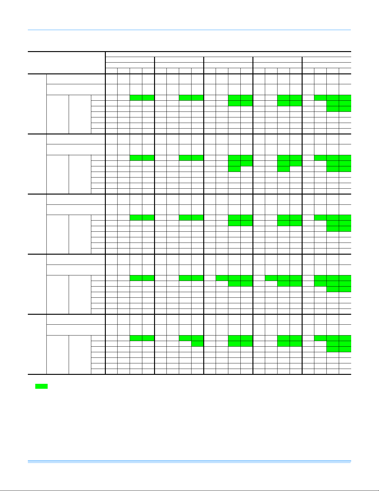
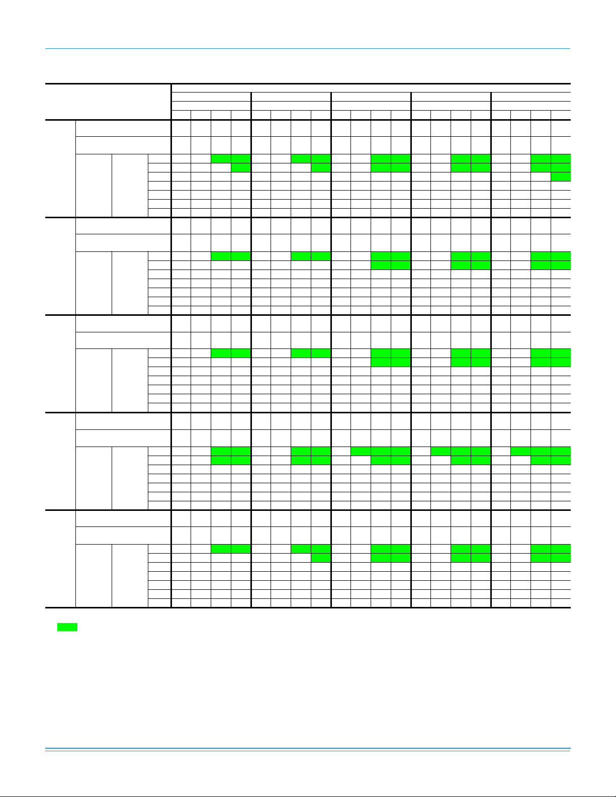
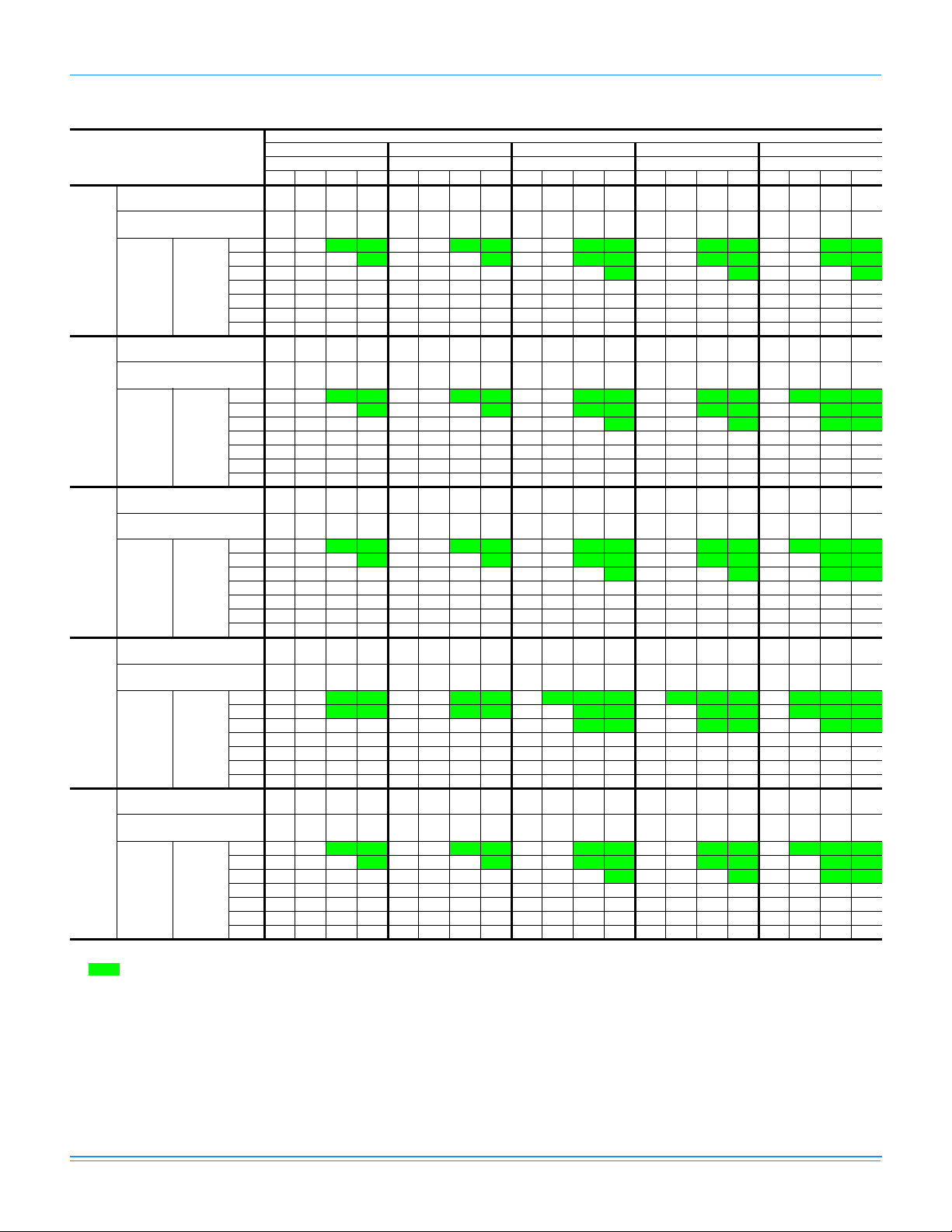
TABLE 8: SIDE AND BOTTOM SUPPLY AIR BLOWER PERFORMANCE
Model No.
DEB
030
(2.5)
036
(3.0)
042
(3.5)
048
(4.0)
060
(5.0)
Blower
Speed
Setting
High --------11715041080486990468888456786444---Medium 1080 351 1021 341 961 331 902 321 841 305 781 290 - - - - - ----Low 810261765240-----------------High - - - - 1440 605 1361 581 1273 555 1185 530 1097 504 1004 480 912 456 - - - Medium 1465 531 1395 512 1325 492 1255 473 1167 446 1079 419 992 392 - - - ----Low 1316 473 1260 455 1204 438 1148 420 1069 396 990 372 911 348 - - - ----High - - - - 1728 725 1633 697 1527 666 1422 635 1317 605 1205 576 1094 547 - - - Medium - - 1674 614 1590 590 1506 567 1400 535 1295 502 1190 470 1063 428 - ----Low 1579 567 1512 546 1444 525 1377 504 1282 476 1188 447 1093 418 - - - ----High - - 1985 870 1939 850 1897 830 1813 800 1728 770 1644 740 1559 707 1474 673 1389 640 - Medium 1694 690 1662 673 1629 657 1597 640 1542 623 1486 607 1431 590 1336 563 1240 537 - - - Low 1385 520 1349 510 1312 500 1276 490 1235 480 - - - - -------High - - - - 2450 1213 2366 1165 2282 1117 2198 1068 2114 1020 1989 993 1864 967 1739 940 - Medium 2339 1170 2275 1118 2211 1067 2147 1015 2083 963 2019 912 1955 860 1854 824 1753 788 1652 752 - Low 1929 940 1877 903 1824 867 1772 830 1720 793 1667 757 1615 720 1586 706 1557 691 1528 677 - -
0.1 0.2 0.3 0.4 0.5 0.6 0.7 0.8 0.9 1.0 1.1
CFM W CFM W CFM W CFM W CFM W CFM W CFM W CFM W CFM W CFM W CFM W
External Static Pressure (Inches Water Gauge)
TABLE 9: ADDITIONAL STATIC RESISTANCE
Resistance, IWG
Description
500 600 700 800 900 1,000 1,100 1,200 1,300 1,400 1,500 1,600
Wet Evaporator Coil .01 .01 .01 .02 .03 .04 .05 .06 .07 .08 .09 .09
Economizer .00 .00 .00 .01 .01 .01 .01 .02 .03 .04 .05 .06
Filter/Frame Kit .01 .02 .02 .02 .02 .02 .03 .03 .03 .03 .04 .05
Electric Heat .02 .03 .03 .03 .04 .04 .05 .06 .07 .08 .09 .10
Note:1. Deduct these resistance values from the available external static pressure shown in the respective Blower Performance Table.
2. The pressure thru the economizer is greater for 100% outdoor air then for 100% return air. If the resistance of the return air duct
system is less then 0.25 IWG, the unit will deliver less CFM during full economizer operation.
CFM
CONTROL WIRING
THERMOSTAT
** =
Minimum wire size of 18 AWG
R
wire should be used for all field
installed 24 volt wire.
G
PROGRAMMABLE
THERMOSTAT ONLY
W
* =
Only required on units with
supplemental electric heat.
C
POWER WIRING
CONTACTOR
FIELD SUPPLIED
DISCONNECT
GROUND
REFER TO ELECTRICAL DATA
LUG
TABLES TO SIZE THE DISCONNECT SWITCH, WIRING AND
OVERCURRENT PROTECTION.
FIGURE 2 - TYPICAL FIELD WIRING DIAGRAM
UNIT TERMINAL STRIP
**
*
THREE
PHASE
POWER
SUPPLY
R
G
Y Y
W
C
TRANSFORMER
CONTACTOR
GROUND
LUG
CAUTION: Label all wires prior to disconnection
when servicing controls. Wiring errors
can cause improper and dangerous
24 VOLT
operation. Verify proper operation
after servicing.
NOTE:
HEAT ANTICIPATOR
SHOULD BE SET AT 0.25
AMPS FOR ALL MODELS
FIELD SUPPLIED
DISCONNECT
REFER TO ELECTRICAL DATA
TABLES TO SIZE THE DISCONNECT SWITCH, WIRING AND
OVERCURRENT PROTECTION.
SINGLE
PHASE
POWER
SUPPLY
Johnson Controls Unitary Products 11
Page 12

360101-XTG-B-0508
TABLE 10: ELECTRICAL DATA
FLA
SUPPLY
AIR
BLOWER
MOTOR
FLA
MINIMUM
CIRCUIT
AMPACITY
MAX.
FUSE
SIZE,
AMPS
MODEL
DEB
POWER
SUPPLY
VOLTAGE
LIMITATIONS
COMPRESSOR
1
MIN. MAX. RLA LRA
COND.
FAN
MOTOR,
30 208/230-1-60 187 253 14.7 73 1.1 2.6 22.1 30 30 0.96 40
36 208/230-1-60 187 253 17.3 94 1.1 3.5 26.2 35 35 0.96 40
42 208/230-1-60 187 253 15.5 86 1.1 3.5 23.9 30 30 0.96 40
48 208/230-1-60 187 253 24.4 140 1.3 4.0 35.8 45 45 0.96 40
60 208/230-1-60 187 253 28.9 165 1.3 4.0 44.4 60 60 0.96 40
36 208/230-3-60 187 253 10.9 78.0 1.1 3.5 18.2 25 25 0.96 75
42 208/230-3-60 187 253 11.5 88.0 1.1 3.5 19.0 25 25 0.96 75
48 208/230-3-60 187 253 14.1 105.0 0.7 4.0 22.3 30 30 0.96 75
60 208/230-3-60 187 253 16.0 125.0 1.3 7.0 28.3 40 40 0.96 75
36 460-3-60 414 504 5.8 40.0 0.6 1.8 9.6 15 15 0.96 75
42 460-3-60 414 504 5.8 42.0 0.6 1.8 9.7 15 15 0.96 75
48 460-3-60 414 504 7.1 55.0 0.6 2.0 11.5 15 15 0.96 75
60 460-3-60 414 504 8.0 67.0 0.7 3.5 14.2 20 20 0.96 75
36 575-3-60 518 630 4.5 32.0 0.4 1.5 7.6 15 15 0.96 75
42 575-3-60 518 630 5.8 44.0 0.4 1.5 9.1 15 15 0.96 75
48 575-3-60 518 630 5.6 44.0 0.6 1.6 9.3 15 15 0.96 75
60 575-3-60 518 630 6.4 50.0 0.6 2.8 11.4 15 15 0.96 75
1. Rated in accordance with ARI Standard 110, utilization range “A”.
2. Dual element, time delay type.
MAX.
HACR
2
BREAKER
SIZE,
AMPS
UNIT
POWER
FACTOR
TRANSFORMER
SIZE (VA)
KW CAP.
MULTIPLIER
.75
.92
ELECTRIC HEAT
CORRECTION
FACTORS
NOMINAL VOLTAGE VOLTAGE
240
208
230
480 460 .92
600 575 .92
TABLE 11: ELECTRICAL DATA (COOLING / ELECTRIC HEAT)
MODEL
DEB
POWER
SUPPLY
030 208/230-1-60 12.0 73.0 1.1 2.6
036 208/230-1-60 17.3 94.0 1.1 3.5
042 208/230-1-60 15.5 86.0 1.1 3.5
048 208/230-1-60 24.4 140.0 1.3 4.0
060 208/230-1-60 38.0 165.0 1.3 7.0
036 208/230-3-60 10.9 78.0 1.1 3.5
COMPRESSOR
RLA LRA FLA FLA MODEL NO. STAGE KW TOTAL AMPS
COND. FAN
MOTORS
SUPPLY
AIR
BLOWER
MOTOR
ELECTRIC HEAT ACCESSORY
2NH04500506 1 3.8/5.0* 18.1/20.8 25.8/29.3 30/30 30/30
2NH04500706 2 5.6/7.5* 27.3/31.3 37.1/42.3 40/45 40/45
2NH04501006 2 7.5/10.0* 36.1/41.7 48.4/55.3 50/60 50/60
2NH04501506 2 11.3/15.0* 54.2/62.5 71.0/81.4 80/90 80/90
2NH04501006 2 7.5/10.0* 36.1/41.7 49.5/56.5 50/60 50/60
2NH04501506 2 11.3/15.0* 54.2/62.5 72.1/82.5 80/90 80/90
2NH04500506 1 3.8/5.0* 18.1/20.8 26.9/30.4 35/35 35/35
2NH04500706 2 5.6/7.5* 27.1/31.3 38.2/43.4 40/45 40/45
2NH04501006 2 7.5/10.0* 36.1/41.7 49.5/56.5 50/60 50/60
2NH04501506 2 11.3/15.0* 54.2/62.5 72.1/82.5 80/90 80/90
2NH04501006 2 7.5/10.0* 36.1/41.7 50.1/57.1 60/60 60/60
2NH04501506 2 11.3/15.0* 54.2/62.5 72.1/83.1 80/90 80/90
2NH04502006 2 15.0/20.0* 72.2/83.3 95.3/109.2 100/110 100/110
2NH04502506 2 18.8/25.0* 90.3/104.2 117.8/135.2 125/150 125/150
2NH04501006 2 7.5/10.0* 36.1/41.7 53.9/60.8 70/70 70/70
2NH04501506 2 11.3/15.0* 54.2/62.5 76.5/86.9 80/90 80/90
2NH04502006 2 15.0/20.0* 72.2/83.3 99.0/112.9 100/125 100/125
2NH04502506 2 18.8/25.0* 90.3/104.2 121.6/139.0 125/150 125/150
2NH04501025 1 7.5/10.0* 20.8/24.1 30.4/34.4 35/35 35/35
2NH04501525 1 11.3/15.0* 31.3/36.1 43.5/49.5 45/50 45/50
MCA
(AMPS)
MAX FUSE/
1
SIZE
(AMPS)
MAX HACR
BREAKER SIZE
2
12 Johnson Controls Unitary Products
Page 13

360101-XTG-B-0508
TABLE 11: ELECTRICAL DATA (COOLING / ELECTRIC HEAT) (CONTINUED)
MODEL
DEB
POWER
SUPPLY
042 208/230-3-60 11.5 88.0 1.1 3.5
048 208/230-3-60 14.1 105.0 0.7 4.0
060 208/230-3-60 16.0 125.0 1.3 7.0
036 460-3-60 5.8 40.0 0.6 1.8
042 460-3-60 5.8 42.0 0.6 1.8
048 460-3-60 7.1 55.0 0.8 2.0
060 460-3-60 8.0 67.0 0.7 3.5
036 575-3-60 4.5 32.0 0.4 1.5
042 575-3-60 5.8 44.0 0.4 1.5
048 575-3-60 5.6 44.0 0.6 1.6
060 575-3-60 6.4 50.0 0.6 2.8
COMPRESSOR
RLA LRA FLA FLA MODEL NO. STAGE KW TOTAL AMPS
COND. FAN
MOTORS
1. Dual element, time delay type.
2. Standard circuit breakers may be used in Canada and on applications over 60 amps where the heaters are separately fused.
SUPPLY
AIR
BLOWER
MOTOR
ELECTRIC HEAT ACCESSORY
(AMPS)
2NH04501025 1 7.5/10.0* 20.8/24.1 30.4/34.4 35/35 35/35
2NH04501525 1 11.3/15.0* 31.3/36.1 43.5/49.5 45/50 45/50
2NP04501025 1 7.5/10.0* 20.8/24.1 31.1/35/1 35/40 35/40
2NP04501525 1 11.3/15.0* 31.3/36.1 44.1/50.1 45/60 45/60
2NP04502025 2 15.0/20.0* 41.7/48.1 57.1/65.1 60/70 60/70
2NH04502525 2 18.8/25.0* 52.1/60.1 70.2/80.2 80/90 80/90
2NH04501025 1 7.5/10.0* 20.8/24.1 34.8/38.8 40/40 40/40
2NH04501525 1 11.3/15.0* 31.3/36.1 47.8/53.9 50/60 50/60
2NH04502025 2 15.0/20.0* 41.7/48.1 60.9/68.9 70/70 70/70
2NH04502525 2 18.8/25.0* 52.1/60.1 73.9/83.9 80/90 80/90
2NH04501046 1 10.0** 12 17.3 20 20
2NH04501546 1 15.0** 18 24.8 25 25
2NH04501046 1 10.0** 12 17.3 20 20
2NH04501546 1 15.0** 18 24.8 25 25
2NP04501046 1 10.0** 12 17.5 20 20
2NH04501546 1 15.0** 18 25.1 30 30
2NH04502046 2 20.0** 24.1 32.6 35 35
2NH04502546 2 25.0** 30.1 40.1 45 45
2NH04501046 1 10.0** 12 19.4 20 20
2NH04501546 1 15.0** 18 26.9 30 30
2NP04502046 2 20.0** 24.1 34.4 35 35
2NP04502546 2 25.0** 30.1 42 45 45
2NH04501058 1 10.0*** 9.6 13.9 15 15
2NH04501558 1 15.0*** 14.4 19.9 20 20
2NH04501058 1 10.0*** 9.6 13.9 15 15
2NH04501558 1 15.0*** 14.4 19.9 20 20
2NH04501058 1 10.0*** 9.6 14 15 15
2NH04501558 1 15.0*** 14.4 20 25 25
2NH04502058 2 20.0*** 19.2 26.1 30 30
2NH04502558 2 25.0*** 24.1 32.1 35 35
2NH04501058 1 10.0*** 9.6 15.5 20 20
2NH04501558 1 15.0*** 14.4 21.5 25 25
2NP04502058 2 20.0*** 19.2 27.6 30 30
2NP04502558 2 25.0*** 24.1 33.6 35 35
MCA
MAX FUSE/
SIZE
(AMPS)
MAX HACR
1
BREAKER SIZE
2
* = KW listed is for 240 volts, use table on previous page for 208 or 230 volts.
** = KW listed is for 480 volts, use table on previous page for 460 volts.
*** = KW listed is for 600 volts, use table on previous page for 575 volts.
Johnson Controls Unitary Products 13
Page 14

360101-XTG-B-0508
HIGH VOLTAGE CONN.
" DIA. KNOCKOUT
HIGH VO
LTAGE CONN.
" DIA. KNOCKOUT
LOW VOLTAGE CONN.
“ DIA. KNOCKOUT
SIDE SUPP
AIR OPENING
LOW VOLTAGE CONN.
LY
SIDE RETURN
AIR OPENING
“ DIA. KNOCKOUT
(OVERALL)
FRONT
2
1
4
HIGH VOLTAGE
CONN.
“ x " DIA.
KNOCKOUT
FRONT
“A”
(OVERALL)
2
(OVERALL)
UNIT CONDENSATE
CONNECTION
P REQUIRED)
(TRA
“ NPTI
COMPRESSOR
RVICE ACCESS
SE
PARTMENT PANEL
COM
UNI
030 - 042
048 - 060
HIGH VOLTAGE CONN.
DIMENSION
T SIZE
33
41
REFRIGERANT
CONNECTIONS
ELECTRICAL/FILTER
RVICE ACCESS
SE
PARTMENT PANEL
COM
" DIA. KNOCKOUT
“A”
6
CONDENSATE
“ NPTI
DRAIN
CLEARANCES
(Minimum)
Front 12"
Bac
k0"
Left Side (Filter Access) 24"
Right Side 24"
Below Unit
Above Unit
1
Units may be installed on combustible floors made from wood or class A,
B or C roof covering material.
2
Units must be installed outdoors. Overhanging structures or shrubs
should not obstruct outdoor air discharge outlet.
1
2
0"
36" (For Condenser
Air Discharge)
CONDENSER
COIL
BOTTOM SUPPLY
AIR OPENING
1
SIDE SUPPLY
AIR OPENING
BACK
SIDE RETURN
AIR OPENING
2
15
15
1
1
15
4
BOTTOM RETURN
AIR OPENING
FIGURE 3 - UNIT DIMENSIONS
14 Johnson Controls Unitary Products
Page 15

360101-XTG-B-0508
TABLE 12: UNIT WEIGHTS
Unit Size
Shipping
Weight
Operating
Weight
ABCD
Corner Weights
030 333 328 85 81 82 86
036 338 333 91 80 78 88
042 347 342 94 83 80 91
048 368 363 92 88 92 97
060 376 371 105 100 84 87
CENTER OF GRAVITY
D
FRONT
OF
UNIT
A
B
26
C
FIGURE 4 - CENTER OF GRAVITY
Economizer
(lbs.)
40
Roof Curb
(lbs.)
8" - 70
14" - 75
Johnson Controls Unitary Products 15
Page 16

TYPICAL APPLICATIONS
SUPPLY AIR
DUCT
RETURN AIR
DUCT
FIELD SUPPLIED
DISCONNECT SWITCH
LOCATED TO REAR OF UNIT
TO POWER SUPPLY
CONTROL WIRING
TO INDOOR
THERMOSTAT
FIGURE 5 - TYPICAL SLAB ON GROUND INSTALLATION
360101-XTG-B-0508
FIELD SUPPLIED
DISCONNECT SWITCH
MOUNTED ON UNIT
TO POWER SUPPLY
ROOF CURB
INSTALLATION
REAR DUCT
CONTROL WIRING
TO INDOOR THERMOSTAT
ROOF CURB
INSTALLATION
BOTTOM DUCT
SLAB ON GROUND
INSTALLATION
RETURN AIR
DUCT
SUPPLY AIR
DUCT
FIGURE 6 - TYPICAL ROOF CURB INSTALLATION
16 Johnson Controls Unitary Products
Page 17

360101-XTG-B-0508
1
OPENING FOR
RETURN AIR DUCT
4
22
14
FRONT
INSULATED
PANELS
RECOMMENDED DUCT SIZE
SUPPLY AIR DUCT
RETURN AIR DUCT
FIGURE 7 - ROOF CURB DIMENSIONS (8” Roof curb also available)
" x 1" WIDE GASKETING FOR CURB FRAME
AND ALL DUCT SUPPORT SURFACES
1"
OPENING FOR
SUPPLY AIR DUCT
WOOD NAILER
" x "
" x "
UNIT BASE RAIL
1
UNIT BASE
WOOD NAILER
8" MIN. ABOVE FINISHED ROOF
CURB FRAME
INSULATION
14"
COUNTERFLASHING
CANT STRIP
INSULATION AND ROOFING MATERIAL
ROOF DECK AND ROOFING MATERIAL
FIGURE 8 - ROOF CURB APPLICATION
Johnson Controls Unitary Products 17
Page 18

360101-XTG-B-0508
OPTIONAL CCH
S / P CONFIGURATION
CCH
BLK
BLK
D / P CONFIGURATION
CCH
BLK
BLK
M1 - 2
T2
DETAIL "A"
L1
T1
2
L
SEE
DETAIL
"A"
L1
2
L
15695BASH0301
FIGURE 9 - TYPICAL WIRIN G DIAGRAM (208/230-1-60 POWER SUPPLY) DEB MODELS
18 Johnson Controls Unitary Products
Page 19

360101-XTG-B-0508
TYPICAL WIRING DIAGRAM NOTES TYPICAL WIRING DIAGRAM LEGEND
- F 9
- 6
-
2 - M 3 , 230V C OIL
(N OT USED)
--
--
FIGURE 10 -TYPICAL WIRING DIAGRAM (208/230-3-60 POWER SUPPLY) DEB MODELS
Johnson Controls Unitary Products 19
Page 20

360101-XTG-B-0508
2
FIGURE 11 -TYPICAL WIRING DIAGRAM (460-3-60 AND 575-3-60 POWER SUPPLY) DEB MODELS
20 Johnson Controls Unitary Products
Page 21

360101-XTG-B-0508
MECHANICAL SPECIFICATIONS
GENERAL DESCRIPTION
Units shall be factory-assembled, single packaged, Electric
Cooling units, designed for outdoor mounted installation. They
shall have built in, equal size, field convertible duct connections
for down discharge supply/return or horizontal discharge
supply/return.
The units shall be factory wired, piped, charged with R-22
refrigerant and factory tested prior to shipment. All unit wiring
shall be both numbered and color coded.
All units shall be manufactured in a facility certified to ISO 9001
standards, and the cooling performance shall be tested in
accordance with ARI test procedures. Units shall be certified to
UL 1995/CAN/CSA C22.2 No. 236 standards.
UNIT CABINET
1. Unit cabinet shall be constructed of galvanized steel, with
exterior surfaces coated with a non-chalking, powdered
paint finish, certified at 1000 hours salt spray test per
ASTMB117 standards.
2. The unit top shall be a single piece “Water Shed” design,
with drip edges and no-seam corners to provide optimum
water integrity
3. Unit shall have a rigidly mounted condenser coil guard to
provide protection from objects and personnel after
installation.
4. Indoor blower section shall be insulated with up to 3/4”
thick, aluminum, foil faced insulation, fastened to prevent
insulation from entering the air stream.
5. Cabinet panels shall be “large” size, easily removable for
servicing and maintenance, with built-in lift handles.
6. Unit shall be built on a formed, “Super-Structure ” design
base pan, with embossments at critical points to add
strength, rigidity and aid in minimizing sound.
7. Full perimeter base rails shall be provided to assure
reliable transit of equipment, overhead rigging, fork truck
access and proper sealing on roof curb applications. Base
rails shall be removable, when required, to lower unit
height.
8. Filters shall be furnished and be accessible through a
removable access door, sealed air tight. (Single phase
models - accessory kit available. Three phase models standard from factory.)
9. Units vertical discharge and return duct configuration sha ll
be designed to fit between standard 24” O.C. beams
without modification to building structure, duct work and
base unit.
10. Condensate pan shall be internally sloped and conform to
ASHRAE 62-89 self-draining standards, with 3/4” NPTI
copper, ridged mount connection.
INDOOR (EVAPORATOR) FAN ASSEMBLY
1. Fan shall be direct drive, multi-speed design. Job site
selected (BHP) brake horse power shall not exceed the
motors nameplate horse power rating.
2. Fan wheel shall be double-inlet type with forward-curved
blades, dynamically balanced to operate smoothly
throughout the entire range of operation. Airflow design
shall be constant air volume.
3. Bearings shall be sealed and permanently lubricated for
longer life and no maintenance.
4. Fan assembly shall be “Slip Track” (slide-out) design for
easy removal and cleaning.
OUTDOOR (CONDENSER) FAN ASSEMBLY
1. The outdoor fan shall be of the direct-driven propeller type,
discharge air vertically, have aluminum blades riveted to
corrosion resistant steel spider bracket and shall be
statically balanced for smooth operation.
2. The outdoor fan motor shall be totally enclosed with
permanently lubricated bearings and internally protected
against overload conditions.
REFRIGERANT COMPONENTS
1. Compressors:
a. Shall be fully hermetic reciprocating type, direct drive,
internally protected with internal high-pressure relief and
over temperature protection. The hermetic motor shall be
suction gas cooled and have a voltage range of + or 10% of the unit nameplate voltage.
b Shall have internal isolation and sound muffling to
minimize vibration and noise, and be externally isolated
on a dedicated, independent mounting.
2. Coils:
a. Evaporator and condenser coils shall have aluminum
plate fins mechanically bonded to seamless internallyenhanced copper tubes with all joints brazed.
b Evaporator and Condenser coils shall be of the direct
expansion, draw-thru design.
3. Refrigerant Circuit and Refrigerant Safety Components
shall include:
a. Independent fixed-orifice expansion devices.
b. Filter/strainer to eliminate any foreign matter.
c. Accessible service gauge connections on both suction
and discharge lines to charge, evacuate, and measure
refrigerant pressure during any necessary servicing or
troubleshooting, without losing charge and without
disrupting condenser or evaporator air flow.
d T he refrigeration system shall provide at least 10° F of
liquid sub-cooling at design conditions.
4. Unit Controls: a. Unit shall contain a large, low voltage Terminal Board for
easy connection of field low voltage wiring.
Johnson Controls Unitary Products 21
Page 22

360101-XTG-B-0508
b. Controls shall be mounted in a large control bo x with tilt-
out, hinged access door, allowing easy access for trouble
shooting and maintenance without affecting the normal
system operation pressures.
c. Unit shall have large, easily removable panels, covering
electrical controls and compressor, allowing ea sy access
for any necessary maintenance or servicing.
ELECTRIC HEATING SECTION
1. An electric heating section, with nickel chromium elements,
shall be provided in a range of 5 thru 25 KW, offering two
stages of capacity - 7 KW and above on single phase
heaters, and 20 KW and above on three phase heaters.
2. The heating section shall have a primary limit control(s)
and automatic reset, to prevent the heating element
system from operating at an excessive temperature.
3. The heating section assembly shall slide out of the unit for
easy maintenance and service.
4. Units with electric heating sections shal l be wired for a
single point power supply, with branch circuit fusing (where
required).
UNIT OPERATING CHARACTERISTICS
1. Unit shall be capable of starting and running at 125° F
outdoor temperature, exceeding maximum load criteria of
ARI Standard 210/240.
2. The compressor, with standard controls, shall be capable
of operation down to 45° F outdoor temperature. Accessory
low ambient kit shall be available for operation to 0° F.
ELECTRICAL REQUIREMENTS
All unit power wiring shall enter unit cabinet at a single factory
provided location and be capable of side or bottom entry, to
minimize roof penetrations and avoid unit field modifications.
Separate side and bottom openings shall be provided for the
control wiring.
22 Johnson Controls Unitary Products
Page 23

360101-XTG-B-0508
Johnson Controls Unitary Products 23
Page 24

Subject to change without notice. Printed in U.S.A. 360101-XTG-B-0508
Copyright © 2008 by Johnson Controls, Inc. All rights reserved. Supersedes: 360101-XTG-A-0108
Johnson Controls Unitary Products
5005 York Drive
Norman, OK 73069
 Loading...