

Page 1

®
SUNLINE 2000
GAS / ELECTRIC
SINGLE PACKAGE AIR CONDITIONERS
INSTALLATION INSTRUCTION
CAUTION
SCROLL COMPRESSORS
OPERATE IN ONLY ONE
DIRECTION.
If the compressor is
experiencing:
- low amperage draw
- similar discharge and
suction pressure
- increased noise level
It is operating in reverse.
Switch two line voltage
connections to correct.
GENERAL
YORK Model DCG units are single package air conditioners
with gas heat desig ned fo r outd oor in st alla tion on a roof top or
a slab.
The units are completely assembled on rigid, permanently
attached base rails. All piping, refrigerant charge, and electrical
wiring is factory-installed and tested. The units require only electric
power, gas piping and duct connections at the point of installation.
The gas-fired heaters have aluminized steel tubular heat
exchangers and spark ignition with intermittent pilot.
This appliance is not to be used for temporary heating of
buildings or structures under construction.
INSPECTION
As soon as a unit is received, it should be inspected for possible
damage during transit. If damage is evident, the extent of the
damage should be noted on the car rier’s freig ht bill. A sepa rate
request for inspec tion by the carr ier’s agent sho uld be made in
writing. Refer to Form 50.15-NM for additional information.
REFERENCE
Additional information on the design, installation, operation and
service of this eq uipment is availa ble in the followi ng reference form s:
55.70-N1 -General Installation
•
55.70-N2 -Pre-start & Post-start Check List
•
530.18-N1.2 V -Economizer Ac ce ss or y
•
530.18-N1.13V -M an. Out door Air Damp er Acc y 0-3 5%
•
530.18-N1.14V -Man. Outdoor Air Damper Accy 0-100%
•
Supersedes: 530. 18 -N 8 Y (2 95)
MODELS D7CG 036, 048 & 060 (10 SEER)
MODEL D2CG 072 (9 EER)
(STYLE A & Belt Drive Option)
Do not store or use gasoline or
other flammable vapors or liquids
in the vicinity of this or any other
appliance
If you smell gas:
1. Open windows
2. Don’t touch electrical switches.
3. Extinguish any open flame.
4. Immediately call your gas supplier.
530.18-N1.12V - Mot oriz ed O utdo or Air Damp er Acc y.
•
530.18-N1.8V -Coil Guard
•
530.18-N2.11V -Low NOx Accessory
•
530.18-N8.2V -High Altitude Accy. (Natural Gas)
•
530.18-N8.3V -High Altit ud e Ac cy. (Propane)
•
530.18-N8.4V -Gas Piping Accessory
•
530.18-N8.12V -Propane Conver sion Accessor
•
690.15-N25V -Low Ambien t Access or y
•
Renewal Parts:
Refer to Part s Manual for comple te listing of repla cement
•
parts on this equipment.
All forms referenced in this instruction may be ordered from:
Publications Distribution Center
Unitary Products Grou p
P.O. Box 1592, York, P A 17405
APPROVALS
Design certified by CGA and UL listed as follows:
1. For use as a forc ed air furnace w ith cooling unit .
2. For outdoor installation only.
3. For installation directly on combustible flooring or, in the U.S.A.,
on wood flooring or Class A, B, or C roof covering material.
4. For use with natural gas and/or propane (LP) gas .
Not suitable for use with conventional venting systems.
530.18-N8Y (1096)
035-14838
FOR YOUR SAFETY
.
Installer should pay particular attention to the words:
the instal lation ea sier . Cautio ns are giv en to prev ent equip ment dam age. W arnings are given to alert installer that personal injury
and/or equipment damage may result if installation procedure is not handled properly.
NOTE, CAUTION
and
WARNING
. Notes are inte nd ed to cl arif y o r make
CAUTION
THIS PRODUCT MUST BE INSTALLED IN STRICT COMPLIANCE WITH THE ENCLOSED INSTALLATION INSTRUCTIONS
AND ANY APPLICABLE LOCAL, STA TE, AND NA TIONAL CODES INCLUDING, BUT NOT LIMITED TO, BUILDING, ELECTRICAL, AND MECHANICAL CODES
WARNING
INCORRECT INSTALLATION MAY CREATE A CONDITION WHERE THE OPERATION OF THE PRODUCT COULD CAUSE
PERSONAL INJURY, PROPER T Y DAM AGE AND/ OR DEATH.
WARNING
DE-ENERGIZE THE ELECTRICAL POWER AND TURN OFF THE GAS SUPPLY TO THE UNIT BEFORE ATTEMPTING TO
INSPECT, REPAIR OR PERFORM MAINT ENANCE TO THE UNIT.
Page 2

530.18-N8Y
TABLE OF CONTENTS
General................................................................................1
Inspection.............................................................................1
Reference ............................................................................1
Approvals ............................................................................. 1
Nomenclature....................................................................... 2
INSTALLATION
Limitations............................................................................3
Location ...............................................................................3
Rigging and Handling .......................................................... 3
Clearances...........................................................................3
Ductwork .............................................................................. 3
Filters ................................................................................... 4
Condensate Drain................................................................4
Service Access..................................................................... 4
Thermostat.................. ........ ........ ........ ........ ........ ........ ........ .4
Power and Control Wiring.................................................... 4
Blower Speed Selection....................................................... 4
Scroll Compressors....................................................... ....... 4
Combustion Discharge........... .. .. .. .......................... .. ...........4
Disconnect Switch Bracket For Optional Belt-Drive ............ 5
Gas Piping .......................................... .. .............. .............. ... 5
Gas Connection.................. .. .. .. .. .............. .............. .............6
L.P. Units, Tanks and Piping ................................................ 6
Low NOx Application......... ...... ...... ...... ...... ...... ...... ...... .... .....6
Ven t and Comb usti on Air Hood s............. .... .... .... .... .... .... .... .7
Optional Economizer Rain Hood...................................7 & 8
OPERATION
Cooling System.................................................................. 15
Cooling Sequence of Operation......................................... 15
Safety Controls (Cooling)........................... ........................ 15
Heating Sequence of Operation ........................................15
Safety Controls (Heating) ..................................................15
Heat Anticipator Setpoints ................................................. 16
Pre-Start Check List...........................................................16
START-UP
Operating Instructions........................................................ 16
Post-Start Check List (Gas)............................................... 16
Manifold Gas Pre ssur e Adju st ment.................... .... .... .... .. .16
Pilot Checkout.................................................................... 17
Burner Instructions.............................................................17
Burner Air Shutt er Adju stment............ .... ...... ...... ...... ...... ...17
Supply Air Blower and Temperat ure Rise Adjus tment.......17
Checking Gas Input ........................................................... 18
Secure Owner’s Approval.................................................. 18
MAINTENANCE & TROUBLE SHOOTING
Normal Maintenance....... .. .. .. .............. .............. .............. ... 19
Cleaning Flue Passages and Heating Elements............... 19
Troubleshooting .........................................................19 & 20
TABLES
No. Description Page
1 Unit Applicatio n Da ta............ .... .... .... .... .... .. 3
2 Gas Heat Application Data.......................... 4
3 Pipe Sizing .... .................... .................. ....... 5
4 Static Resistances ...................................... 8
5 Physical Data.............................................. 9
6 Supply Air Blower Perf
. 3 - 6 Ton Direct-Drive
7 Motor & Drive Data-Belt-Drive Blower........ 9
8 Supply Air Blower Perf. 3 & 4 Ton Belt-Drive 10
9 Supply Air Blower Perf. 5 & 6 T on Belt-Drive 11
10 Electrical Data Direct- D ri ve.. .. ..................... 12
11 Electrical Data Belt-Drive............................ 12
12 Superheat, 036 ........................................... 12
13 Superheat, 048 ........................................... 13
14 Superheat, 060 ........................................... 13
15 Superheat, 072 ........................................... 13
16 Limit Control Setting ................................... 16
17 Belt Drive Supply Air Mot or Pulle y Adj........ 17
18 Gas Rate - Cubic Feet Per Hour ................ 18
FIGURES
No. Description Page
1 Recommended Drain Piping....................... 4
2 Typical Field Wiring..................................... 5
3 External Supply Connecti on ....................... 6
4 Bottom Supply Connection......................... 6
5 Ven t and Comb usti on Air Hood s......... .... .... 7
6 Economizer Rain Hoo d Assem bly.............. 7
7 Enthalpy Setpoint Adjustment..................... 8
8 Center of Gravity......................................... 9
9 Dimensions and Clearances....................... 14
10 Gas Valve Piping........................... .............. 15
11 Gas Valves.................... .......................... .. .. 16
12 Proper Flame Adjustm ent.................. ...... ... 17
13 Typ ical F lam e Ap pear ance...................... ... 17
14 Belt Adjustment.................... .......... .......... ... 17
15 Press. Drop versus Supply Air CFM........... 18
9
PRODUCT NOMENCLAT URE
D 7 C G 4N
PRODUCT CATEGORY
D = Single Package Air Conditioner
(Air Cooled)
PRODUCT GENERAT ION
2 = 2nd Generation
7 = 7th Generation
PRODUCT IDENTIFIER
CG = Gas/El ectric
2 Unitary Products Group
NOMINAL COOLING
CAPACITY
036 = 3 Ton
048 = 4 Ton
060 = 5 Ton
072 = 6 Ton
0 030 6 2 5
FACTORY INSTALLED
HEAT
N = Gas Heat Installed
VOLTAGE CODE
06 = 208/230-1-60
25 = 208/230-3-60
46 = 460-3-60
58 = 575-3-60
NOMINAL GAS HEATING
OUTPUT CAP ACITY
040 = 40 MBH
060 = 60 MBH
079 = 79 MBH
099 = 99 MBH
Page 3

INSTALLATION
LIMITATIONS
These units mu st be installe d in accorda nce with the cu rrent
editions of the following national and local safety codes:
In the U.S.A.:
1. National Electrical Co de AN SI /N F PA No . 70 .
2. National Fuel Gas Code Z223.1.
3. Gas-Fired Central Furnace Standard ANSI Z21.47-1993.
4. Local gas utility re quirements.
In Canada:
1. Canadian Electrical Code CSA C22.1
2. Current Gas Installation Codes CAN/CGA-2.3-M93.
3. Local plumbing and was t e water codes.
4. Other applicable local codes.
Refer to Table 1 for Unit Application Data and to T able 2 for Gas
Heat Application Data.
If components are to be added to a unit to meet local codes, they
are to be installed at the dealer’s and / or the customer’s expense.
Size of unit fo r pr op os ed ins tall at io n sh ou ld be base d on hea t
loss / heat gain calculation made according to the methods of
Air Conditioning Contractors of America (ACCA).
TABLE 1
Voltage Variation
Min. / Max.
Supply Air CFM, Nom. 1200 1600 2000 2400
Wet Bulb Temperature (°F) of
Air on Evaporator Coil,
Min. / Max.
Dry Bulb Temperature (°F) of
Air on Condenser Coil,
Min.
1
Utilization range “A” in accordance with ARI St anda rd 110.
2
A low ambient accessory is available for operation down to 0°F.
LOCATION
Use the follow ing guidelines to selec t a suitable location for
these units.
1. Unit i s designed for outdo or installation only.
2. Condenser coils must have an unlimited supply of air.
WARNING:Excessive exposure of this furnace to contami-
3. For ground level installation, a level pad or slab should be
- UNIT APPLICATION DATA
UNIT SIZE 036 048 060 072
208/230V 187 / 253
460V 414 / 504
1
575V 518/630
57 / 72 57 / 72 57 / 72 57 / 72
2
/ Max.
Where a choice of location is possible, p os ition the unit on
either north or east side of building.
nated combustion air may result equipment damage or personal injury. Typical contaminates
include: permanent wave solutions, chlorinated
waxes and cleaners, chlorine based swimming
pool chemicals, water softening chemicals, carbon
tetrachloride, Halogen type refrigerants, cleaning
solvents (e.g. perchloroethylene), printing inks,
paint removers, varnishes, hydrochloric acid, cements and glues, antistatic fabric softeners for
clothes dryers, masonry acid washing materials.
used. The thic kness and size of the pad or sl ab used should
meet local codes and unit weight. Do not tie the slab to the
building foundation.
45 / 120 45 / 120 45 / 120 45 / 120
530.18-N8Y
4. Roof structures must be able to support the weight of the unit
and its options and / or accessories. Unit must be installed on
a solid level roof curb or appropriate angle iron frame.
CAUTION: If a unit i s to be in st al le d o n a roof cu rb or sp ec ia l
frame other than a YORK roof curb, gasketing must
be applied to all su rfaces that come in con tact w ith
the unit underside.
5. Maintain level tolerance to 1/2" maximum across the entire
length or width of the unit.
6. Elevate the unit sufficiently to prevent any blockage of the
air entrances by snow in areas where there will be snow
accumulation. Check the local weather bureau for the
expected snow accumulation in your area.
RIGGING AND HANDLING
Exercise care when moving the unit. Do not remove any
packaging unti l the unit is ne ar the place of installa tion. Rig the
unit by attaching chain or cable slings to the lifting holes
provided in the base rails. Spreaders, whose length exceeds
the largest d imension a cross the un it, MUST be used acr oss
the top of the unit.
BEFORE LIFTING A UNIT, MAKE SURE THAT ITS WEIGHT
IS DISTRIBUTED EQUALLY ON THE CABLES SO THAT IT
WILL LIFT EVENLY.
Units may also be moved or lifted with a forklift. Slotted
openings in the base rails are provided for this purpose.
LENGTH OF FORKS MUST BE A MINIMUM OF 42".
Remove the nesting brackets from the four corners on top of
the unit. All screws that are removed when taking these
brackets off must be replaced on the unit.
CAUTION: An adhesive backed label is provided over the
outside of the co mbu st ion ai r in le t op en in g to prevent moisture from entering the unit whic h could
cause damage to electrical components. Allow this
closure label to remain in place until the combustion air hood i s to be installed (r efer to Figure 5).
Refer to Table 5 for unit weights and to Figure 8 for approximate
center of gravity.
CLEARANCES
All units require certain clearances for proper operation and
service. Installer must make provisions for adequate combustion
and ventilation air in accordance with Section 5.3, Air for
Combustion and Ventilation of the National Fuel Gas Code, ANSI
Z223.1 (in U.S.A.) or Sections 7.2, 7.3 or 7.4 of Gas Installation
Codes CAN/CGA-B149.1 and .2 (in Canada) and/or applicable
provisions of the local building codes. Refer to Figure 9 for the
clearances required for combustible construction, servicing,
and proper unit op er ation.
WARNING: Do not permit overhanging structures or shrubs to
obstruct condenser air discharge outlet, combustion
air inlet or vent outlet.
DUCTWORK
Ductwork should be designed and sized ac cording to the metho ds
in Manual Q of th e Air Conditioning Contrac tors of America (ACCA).
A closed return duct system shall be used. This shall not preclude
use of economizers or outdoor fresh air intake. The supply and
return air duct connections at the unit should be made with flexible
joints to minimize the transmission of noise.
Unitary Products Group 3
Page 4
530.18-N8Y
The supply and return air duct systems should be designed for the
CFM and static requirements of the job. They should NO T be sized
to match the dimensions of the duct connections on the unit.
CAUTION: When fastening ductwork to the side duct flanges on
the unit, insert the screws through the duct flanges
only . DO NOT insert the screws through the casing.
Outdoor ductwork must be insulated and waterproofed.
Refer to Fig ure 9 for i nformatio n concerni ng side and bo ttom
supply and return air duct openings.
FILTERS
1" filters ar e supp lied with each un it. 2" r eplace ment filt ers m ay
be used wi th no modification to th e filter racks. Filters must
always be installed ahead of the evaporator coil and must be
kept clean or re placed wit h same size and t ype. Dir ty filt ers will
reduce the cap acit y of t he un it an d wi ll re sult in fros ted coil s or
safety shutdown. Minimum filter area and required sizes are
shown in Table 5.
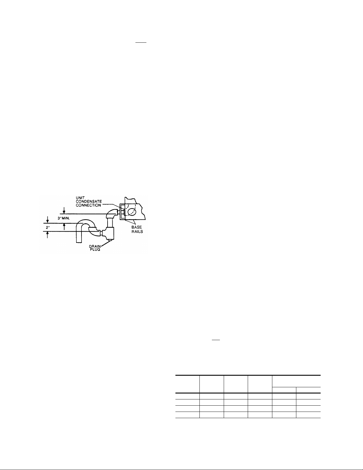
CONDENSATE DRAIN
Plumbing must conform to local codes. Use a sealing compound
on male pipe threads. Install a condensate drain line from the 3/4"
PVC female connection on the unit to spill into an open drain.
NOTE: The condensate drain line MUST be tr apped to provi de
proper drainage. See Figure 1.
POWER AND CONTROL WIRING
Field wiring to the unit must conform to provisions of the National
Electrical Code (NEC), ANSI / NFPA 70-1987 (in U.S.A.) current
Canadian Electric Code (CEC) C22.1 (in Canada), and / or local
ordinances. The unit must be electrically grounded in accordance
with the N.E.C. ANSI / NFP A 70 or local codes.
Voltage tolerances which must be maintained at the
compressor terminals during start-up and running conditions
are indicated on the unit Rating Plate an d Table 1.
The internal wiring harness furnished with this unit is an integral
part of a UL and CGA design certif ied unit. Fi eld altera tion to
comply with electrical codes should not be required.
A disconnect switch shou ld b e fi eld provid ed f or the u nit. The
switch must be separat e from al l other ci rcuits . Refer to Fi gure
9 for installation location. If any of the wire supplied with the
unit must be replaced, replacement wire must be of the type
shown on the wirin g di ag ra m .
Electrical lines must be sized properly to carry the load. USE COPPER
CONDUCTORS ONLY. Each unit must be wired with a separate
branch circuit fed directly from the meter panel and properly protected.
CAUTION: When connecting electrical power and control wir-
ing to the unit, w aterproo f type connecto rs MUST
BE USED so that water or moisture cannot be
drawn into t he unit during nor mal operation. The
above waterproofing conditions will also apply
when installing a field-supplied disconnect switch.
Refer to Figure 2 for typical field wiring and to the appropriate unit
wiring diagram for control circuit and power wiring information.
FIG. 1
- RECOMMENDED DRAIN PIPING
SERVICE ACCESS
Access to all serviceable components is provided by the
following removable panels:
•
Scroll compressor compartment
•
Burner compartment
•
Blower compartment
•
Main control bo x
•
Filter compartment
•
Motor access (on units with belt-drive option)
Refer to Figure 9 for location of these access panels.
CAUTION: Make sure that all scre ws a re re pl ac ed on the unit
to maintain an air-tight seal.
THERMOSTAT
The room thermostat should be located on an inside wall
approximatel y 5 6" ab ove the flo or wh ere it will not be subj ect
to drafts, sun exposure, or heat from electrical fixtures or
appliances. Follow manufacturer’s instructions enclosed with
thermostat for general installation procedure. Color coded
insulated wires (#18 AWG) should be used to connect
thermostat to unit. See Figure 2 for wiring details.
NOTE : If the unit has an economizer, remove jumper J1 from
terminals 8 and 10 on the relay board to prevent simultaneous operation of the scroll compressor and the economizer. If you want to energize the scroll compressor for
supplemental cooling during the economizer operation,
use a thermostat with two stages of cooling.
BLOWER SPEED SELECTION
Three blowe r motor spee ds are ava ilable on the direct- drive
units. The speed selection for the direct-drive units is
determined by the CFM and ESP requirements of the
applications . All units with belt- driv e option have an adjust able
motor pulley to achieve the above conditions.
All direct-drive units with 208/230 voltage are shipped with the
wire labeled # 116 connected to the "HIG H" speed tap on the
blower motor. If a lower blower motor speed is desired, this wire
should be move d to the "MED" or "LOW " speed tap on the
motor for the speed desired.
All direct-drive units with 460 and 575 voltage are shipped with
the wire labeled #116 connected to the "HIGH" speed tap on
the blower motor. If the medium speed is required, connect wire
#116 to the "MED" speed tap and the blue motor lead to the
"HIGH" speed ta p. If the low speed is required, conn ect wire
#1 16 to the "LOW" sp eed tap, the blue mot or lead to the "H IGH"
speed tap and t he orange motor lead to the " M ED" speed tap.
SCROLL COMPRESSOR
These units are shipped with the scroll compressor mountings
factory-adjusted and ready for operation.
CAUTION: Do Not loosen the scroll compressor mounting bolts.
COMBUSTION DISCHARGE
The products of combustion are discharged horizontally
through a screened opening on the gas heat access panel.
TABLE 2
Capacity,
(Mbh)
NOTE: Gas Heaters are shipped available for natural gas, but can be converted to L.P . with Kit Model
No. 1NP0434. All furnaces meet the latest California seasonal efficiency requirements.
1
Based on 1075 Btu/Ft3.
2
The air flow must be adjusted to obtain a temperature rise within the range shown.
- GAS HEA T APPLICA T ION DATA
Input
50 40 3 Ton 47 15 45
75 60 4 Ton 70 25 55
100 79 3/5/6 Ton 93 40/25/25 70/55/55
125 99 4/5/6 Ton 116 45/35/35 75/65/65
Output
Capacity,
(Mbh)
Available
on
Models
Gas Rate
(Ft.3/Hr.)
Temp. Rise °F
1
At Full Input
Min. Max.
2
4 Unitary Products Group
Page 5

COOLING / HEATING (24 VOLT THERMOSTAT )
THERMOSTAT
TERMINALS
1
UNIT TERMINAL
STRIP TB1
ADD
JUMPER
24 VOLT
TRANSFORMER
TYPICAL CONTROL WIRING
COOLING / HEATING (24 VOL T ELECTRONIC THERMOSTAT)
THERMOSTAT
TERMINALS
ADD
JUMPER
4
ADD
JUMPER
NOT
USED
1
4
UNIT TERMINAL
STRIP TB1
2
3
530.18-N8Y
24 VOLT
TRANSFORMER
1
24 VOLT THERMOSTAT 2TH07701024. IF THE UNIT HAS AN ECONOMIZER,
REMOVE JUMPER J1 FROM TERMINALS 8 AND 10 ON THE RELAY BOARD
TO PREVENT SIMULTANEOUS OPERATION OF THE SCROLL CO MPRESSOR
AND THE ECONOMIZER. IF YOU WANT TO CONTROL THE ECONOMIZER ON A
SECOND STAGE OF COOLING OR HAVE AN ELECTRIC HEAT ACCESSORY
WITH TWO STAGES OF HEAT, USE THERMOSTAT 2TH04701024.
COOLING / HEATING (24 VOL T ELECTRONIC THERMOSTAT)
THERMOSTAT
TERMINALS
1
UNIT TERMINAL
STRIP TB1
ADD
JUMPER
24 VOLT
TRANSFORMER
TYPICAL POWER WIRING
REFER TO ELECTRICAL DATA
TABLES TO SIZE THE DISCONNECT
SWITCH, WIRING & OVERCURRENT
PROTECTION.
TO REMOTE SENSOR
1
ELECTRONIC PROGRAMMABLE THERMOSTAT 2ET04700224 (INCLUDES SUBBASE)
TO CONTROL ECONOMIZER ON SECOND STAGE OF COOLING, REMOVE JUMPER
J1 FROM TERMINALS 8 AND 10 ON THE RELAY BOARD.
2
SECOND STAGE COOLING IS NOT REQUIRED ON UNITS LESS ECONOMIZER.
3
SECOND STAGE HEATING IS ONLY REQUIRED ON UNITS WITH A TWO STAGE
ELECTRIC HEATER.
4
REMOVE JUMPER J2 FROM TERMINALS 4 AND 9 ON JUMPER PLUG CONNECTOR
P6 ON UNITS WITH ECONOMIZER. TERMINALS A1 AND A2 PROVIDE A RELAY
OUT-PUT TO CLOSE THE OUTDOOR ECONOMIZER DAMPERS WHEN THE
THERMOSTA T SWITCHES TO THE SET-BACK POSITION.
1
ELECTRONIC PROGRAMMABLE THERMOSTAT 2ET07701024 (INCLUDES SUBBASE).
IF THIS UNIT HAS AN ECONOMIZER, REMOVE JUMPER J1 FROM TERMINALS 8 AND
10 ON THE RELAY BOARD TO PREVENT SIMUL TANEOUS OPERATION OF THE
SCROLL COMPRESSOR AND THE ECONOMIZER. IF YOU WANT TO CONTROL THE
ECONOMIZER ON A SECOND STAG E OF COOLING, USE THERMOSTAT 2ET04700224.
2TH04702224 IF USED
CAUTION: Label all wires prior t o disconnection when servic-
ing controls. Wiring errors can cause improper and
dangerous op eration. Verify pro pe r operation af te r
servicing.
REFER TO ELECTRICAL DATA
TABLES TO SIZE THE DISCONNECT
SWITCH, WIRING & OVERCURRENT
PROTECTION.
FIG. 2
- TYPICAL FIELD WIRING
DISCONNECT SWITCH BRACKET FOR UNITS
WITH OPTIONAL BELT-DRIVE BLOWER
the current Gas Installatio n Codes CAN/CGA-B149.1 and .2 ( in
Canada) should be followed in all cases unless superseded by
local codes or gas com p an y re qu irements. Refer to Table 3.
A special bracket for mounting a field-supplied disconnect
switch is provided in each unit ordered with an optional
belt-drive supply air blower. The bracket is shipped inside the
blower compartment taped to the top of the blower housing.
Install the bracket on the le ft hand side of the unit as sho w n in
Figure 9. Several existing screws at the top of the unit and one
screw approximately midway down from the top will be used
for mounting t he brack et. Sc rews shou ld be lo osened on ly NOT REMOVED. Matching holes in the bracket have
elongated keyways allowing easy installation. Re-tighten
screws after bracket is in place to ensure panels will remain
leak tight.
GAS PIPING
Proper sizing of gas p ipin g de pend s on the cub ic fee t pe r ho ur
of gas flow required, specific gravity of the gas and the length
of run. “National Fuel Gas Code” Z223-1992 (in the U.S.A.), or
Unitary Products Group 5
TABLE 3
Length in Feet
Maximum capacity of pipe in cubic feet of gas per hour. (Based upon a pressure drop of 0.3
inch water column and 0.6 spe ci fic gr avit y gas) .
- PIPE SIZING
10
20
30
40
50
60
70
80
90
100
Nominal Iron Pipe Size
1/2 in. 3/4 in. 1 in. 1-1/4 in.
132
92
73
63
56
50
46
43
40
38
278
190
152
130
115
105
96
90
84
79
520
350
285
245
215
195
180
170
160
150
1,050
730
590
500
440
400
370
350
320
305
Page 6

530.18-N8Y
FIG. 3
- EXTERNAL SUPPLY CONNECTION
EXTERNAL SHUT-OFF
FIG. 4
- BOTTOM SUPPLY CONNECTION
EXTERNAL SHUT-OFF
The heating value of the gas may differ with locality. The value
should be checke d w it h th e lo ca l gas utility.
NOTE: There may be a local gas utility requirement specifying
a minimum diameter for gas piping. All units require a
1/2 inch pipe connection at the entrance fitting.
GAS CONNECTION
The gas supply line can be routed through the knockouts
located on the front of the unit or through th e opening pr ovided
in the unit’s base. Refer to Figure 9 to locate these access
openings. Typical supp ly piping arrangements a re shown in
Figures 3 and 4. All shaded items are field-supplied.
Two grommets are shipped in the blower compartment (in parts
bag taped to the blower housing) of every unit with gas heat
and should be used in the knockouts when the gas piping
penetrates the f ro nt of th e un it .
After the gas supply piping has been installed, the bottom
opening shou ld be sealed to prevent water f rom leaking into
the building.
Gas piping recommendations:
1. A drip leg and a ground joint union must be installed in the
gas piping.
2. When required by local codes, a manual shut-off valve may
have to be installed outside of the unit.
3. Use wrought iron or steel pipe for all gas lines. Pipe
compound should be applied sparingly to male threads
only.
WARNING:Natural gas may cont ain some pr op an e. Propane,
4. All piping should b e cleaned of dirt and scale by hamm ering
on the outside of the pipe and blowing out the loose dirt and
scale. Before initial start-up, be sure that all of the gas lines
external to the unit have been purged of air.
5. The gas supply should be a separate line and installed in
accordance with all safety codes as prescribed under
“Limitations”. After the gas connections have been
completed, o pen the main shut -off val ve ad mitting
gas pressu re
soap solution or other material su itable for the purpose.
NEVER USE A FLAME.
being an excellent solvent, will quickly dissolve
white lead or most standard commercial compounds. Therefore, a special pipe compound must
be applied when wrought iron or steel pipe is used.
Shellac base compounds such as Gaskolac or
Stalastic, and compounds such as Rectorseal #5,
Cyde’s or John Crane may be used.
normal
to the mains. Che ck all joint s for leaks wit h
6. The furnace and its individual manual shut-off valve must
be disconnected from the gas supply piping system during
any pressure testing of that system at test pressures in
excess of 1/2 psig (3. 48kPa).
The furnace mu st be isolated from the gas supply piping
system by closing its individual manual shut-off valve during
any pressure t esting of th e gas supply piping syst em at te st
pressures equa l to or le ss tha n 1/ 2 ps ig (3.48kPa).
7. A 1/8 inch NPT plug ged tappin g, acces sible for te st gage
connection, must be installed immediately upstream of the
gas supply connection to the furnace.
L.P./PROP ANE UNITS, TANKS AND PIPING
All gas heat units are shipped from the factory equipped for natural
gas use only. The unit may be converted in the field for use with
L.P./propane gas with accessory kit model number 1NP0440.
All L.P./propane gas equipment must conform to the safety
standards of t he National Fi re Protection Asso ci ation.
For satisfactory operation, L.P ./propane gas pressure must be
10.5 inch W.C at the unit under full load. Maintaining proper gas
pressure depe nds on three main facto rs:
1. The vaporization rate which depends on (a) the
temperature of t he liquid and (b) the “wetted surface” area
of the container or containers.
2. The pr oper pressure regulat ion. (Two-stage regulation is
recommended from the standpoint of both cost and
efficiency.)
3. The pressure drop in the lines between regulators and
between the second stage regulator and the appliance.
Pipe size requi red wi ll depe nd on th e lengt h of th e pipe run
and the total load of all appliances.
Complete information regarding tank sizing for vaporization,
recommended regulator settings, and pipe sizing is available from
most regulator manufacturers and L.P./propane gas suppliers.
L.P./propane gas is an excellent solvent and special pipe
compound must be u se d whe n as se mbl ing pi pi ng for thi s ga s
as it will quickly dissolve white lead or most standard
commercial compounds. Shellac base compounds such as
Rectorseal #5 are satisfactory for this type of gas.
Check all connections for leaks when piping is completed,
using a soap soluti on . NEVER USE A FLAME.
LOW NOx APPLICA TION
For natural gas heat installations in locations which require low
Nitros Oxide emiss ions, accessory model 1LN0 404 must be
installed.
6 Unitary Products Group
Page 7

VENT AND COMBUSTION AIR HOODS
The vent and combustion air hoods are shipped attached to the
blower housing in the blower compartm ent. T hese hoods m ust
be installed on the outside of the gas heat access panel to
ensure proper unit func tion. The necessary mo unting sc rews
are provided in a bag also attached to the blower housing.
The screen for the comb ustion air intake ho od is secu red to the
inside of the a ccess panel open ing with thre e fasteners an d the
screws used for mo unting the hood t o the panel. The top flange
of this hood s li ps i n under the top of the ac ce ss pa nel opening
when installing. Refer to Figure 5. Remove the protective label
covering the opening just prior to installing this hood.
The vent hood (including its screen) is installed by inserting the
top flange of the hood into the slotted opening in the access
panel. The top screw secures the hood to the access panel.
The remaining two side screws must be installed after the
access panel is insta lled on the unit . These screws en gage the
bottom flue box flange.
CAUTION: All three screws in th e ven t hoo d mu st be pr oper ly
installed bef ore furnace oper ation to insure a ll combustion products are exhausted from the unit.
FIG. 5
- VENT AND COMBUSTION AIR HOODS
OPTIONAL ECONOMIZER RAIN HOOD
The following procedure should be used when assembling an
economizer rain hood onto a unit. Refer to Figure 6. The
outdoor and return air dampers, damper actuator, the linkage
and all the controls are factory mounted as part of the
economizer option.
All of the hood com pon ents , in clud ing the filt er s, t he g aske ting
and the hardware for assembling are located ab ove the top filter
racks with in the fil ter se ctio n. The outd oor a ir sens or is in th e
bag of parts locat ed at the bottom of t he return air sectio n.
HOOD
COVER
FILTER
COVER
GASKETED
FLANGE
1. With filter section access panel removed, take out hood
components, filters and sensor described above. Remove
and discard outdoor air opening cover on back unit (Upper
right hand corner).
2. Remove the 1/2" knockout (A) in the units rear panel
(located to the right side of th e o ut do or air opening). Insert
the two loose wires from inside the unit, into the 1/2"
bushing provided. Insert wires and bushing into knockout.
Snap bushing into place.
3. Mount t he ou tdoo r air se nsor to the rear panel , just bel ow
the knockout described in Step 2. Secure with two
self-drilling screws at dimples (B) provided in the panel.
NOTE: Sensor must be positioned so that the sensing ports
are at the top (louvers pointing downward) and terminal
connections to the right.
4. Connect the two wires, indicated in Step 2, to the sensor
as follows:
•
Wire #73 to terminal (+)
•
Wire #74 to terminal (S)
5. Assemble the LH and RH side plates to the top cover (2
screws each side) to form the hood. Apply gasketing to the
flange surface on each side plate. Extend gasketing 1/4"
beyond top and bottom of each flange to insure adequate
corner sealing. Secure this assembly to the unit back panel
(upper right hand corner). First, remove screw (C) on unit
top cover . Then sl ip flan ge of ho od co ver in u nder f lange of
unit top cover , replace screw (C), engagi ng hole (E) in ho od
flange and tighten. Attach the two side p lates to the uni t
panel by us ing two s elf-dr illing screws f or each side pl ate
at dimples (D) provided in the panel.
6. P osition fillpiece at bottom of hood, between the two side
plates but do not secure at this time. (Slotted openings MUST
be downward for drainage). After fillpiece is properly positioned, note where contact is made with the unit panel. Remove fillpiece and apply gasket material to this area to provide
a seal. Reposition fillpiece and secure with 2 screws.
7. Install the two filters into the hood assembly, sliding down
along retainers on side plates, into fillpiece at bottom of
hood.
OUTDOOR AIR
OPENING COVER
D
E
D
C
OUTDOOR AIR
D
A
B
D
SENSOR
GASKET
530.18-N8Y
L. H. SIDE
PLATE
GASKETED
FLANGE
FILTERS
FILLPIECE
FIG. 6
- ECONOMIZER RAIN HOOD ASSEMBLY (OPTION)
Unitary Products Group 7
R. H.
SIDE
PLATE
SIDE DUCT
APPLICATION SHOWN
FILTER SECTION
ACCESS PANEL
Page 8

530.18-N8Y
NOTE: Install filters so that “Air Flow” arrows point toward the
unit.
8. Install filter cover over the end of the hood with one screw
(center of hood), securing filters into posit ion.
CAUTION: When procee ding with Steps 9 a nd 10, extreme
care must be ex ercise d wh ile tur ning both the se t
point and minimum position adjusting screws to
prevent twistin g th em of f.
9. The enthalpy set po in t for the dampers may now b e set by
selecting the desired set point from graph in Figure 7. For
a s ingle enth alpy econom izer, carefully turn th e set point
adjusting screw to the “A”, “B”, “C” or “D” setting corresponding to the lettered curve. For a dual ent ha lp y ec on omizer, carefully turn the set point adjusting screw fully
clockwise past the “D” setting.
10.To check that the damper blades move smoothly without
binding, carefully turn the minimum position adjusting
screw fully clockwise and th en energize and de -energize
terminals “ R” to “G”. Wi th terminal s “R” to “G” en ergized,
turn the mi nimum po sition s crew c ountercl ockwise until the
desired minimum position has been attained.
1 1. Replace the filter section access panel.
FIG. 7
- ENTHALPY SET POINT ADJUSTMENT
TABLE 4
Economizer
Bottom Duct Connections
1
Deduct these resistance values from the available external static pressure shown in the respective Blower Performance T able.
2
The pressure thru the economizer is greater for 100% outdoor air than for 100% return air. If the resistance of the return air duct system is less than 0.25 IWG, the unit will deliver less CFM
8 Unitary Products Group
- STATIC RESISTANCES
DESCRIPTION
1, 2
1
EXTERNAL STATIC PRESSURE DROP
RESISTANCE, IWG
CFM
1000 1200 1400 1600 1800 2000 2200 2400 2600 2800 3000
0.07 0.08 0.09 0.11 0.13 0.15 0.17 0.20 0.23 0.26 0.30
0.06 0.07 0.08 0.09 0.10 0.11 0.12 0.14 0.16 0.19 0.22
Page 9

TABLE 5
- PHYSICAL DATA
MODELS
CENTRIFUGAL BLOWER
(Dia. x Wd. in.)
EVAP.
BLOWER
FAN MOTOR HP
(Direct-Drive)
FAN MOTOR HP
(Belt-Drive)
EVAP.
COIL
COMPR.
TYPE
COND.
FAN
COND.
COIL
ROWS DEEP
FINS PER INCH
FACE AREA (Sq. Ft.)
HERMETICALLY SEALED SCROLL TYPE
PROPELLER DIA. (in.)
FAN MOTOR HP
NOM. CFM TOTAL
ROWS DEEP
FINS PER INCH
FACE AREA (Sq. Ft.)
QUANTITY PER UNIT
AIR
FILTERS
(SEE NOTE)
(15" x 20" x 1")
QUANTITY PER UNIT
(14" X 25" X 1")
TOTAL FACE AREA
(sq. ft.)
CHARGE
NOTE: Filter racks are adapted for 1" or 2" thick filters.
CORNER D
REFRIGERANT 22
(lbs./oz.)
APPROXIMATE
CENTER OF
GRAVITY
BACK
CORNER C
UNIT SIZE
036 048 060 072
12 x 10
12 x 10
12 x 10
1
3
⁄
⁄
2
1
⁄
1
3
13
3.6
24
1
⁄
4
3,400
1
16
17.1
2
1
6.3
1
2
13
4.3
24
1
3,400
16
17.1
6.3
1
4
1
1
3
⁄
1
⁄
2
2
3
13
5.1
24
1
⁄
⁄
4
4
3,400
1
1
22
17.1
2
2
1
1
6.3
5/8 6/8 6/8 10/0
CONDENSER
COIL END
CORNER B
FRONT
12 x 11
1
1
⁄
1
2
4
13
5.1
24
1
⁄
4
3,300
2
16
16.7
2
1
6.3
530.18-N8Y
WEIGHTS
UNIT
SIZE
(heat)
UNIT
WEIGHT*
(lbs.)
CORNER WEIGHTS*
(location, lbs., see figure 8)
"A" "B" "C" "D"
036 (40 Mbh) 625 180 172 133 140
036 (79 Mbh) 635 180 177 138 140
048 (60 Mbh) 675 193 185 145 152
048 (99 Mbh) 685 193 190 150 152
060 (79 Mbh) 700 200 192 150 158
060 (99 Mbh) 710 200 197 155 158
072 (79 Mbh) 775 186 209 201 179
072 (99 Mbh) 785 186 214 206 179
OPTIONS / ACCESSORI ES WEIGHTS (lbs.)
Economizer 50
Motorized Outdoor
Air Damper
Barometric Relief/Fixed
Outdoor Air Intake Damper
26
10
Roof Mounting Curb 92
Belt-Drive Blower 5
* Weight = Unit + Economizer
48-11/32
1
⁄
82
“
7
32-1/8
⁄
44
“
8
Y
15-1/4
FIG 8
- CENTER OF GRAVITY
TABLE 6
- SUPPLY AIR PERFORMANCE
X
21
GAS HEAT VALUES SHOWN @ 230/460/575 Volts
UNIT
SIZE
036
048
060
072 HI 2461 1480 2402 1440 2361 1395 2260 1350 2178 1305 2101 1260 2000 1205 1914 1155 1830 1 110
NOTE: For 208 volts,multiply values by 0.95.
*Includes allowances for a wet evaporator coil, 1" filters and gas fired heat exchangers. Refer to Table 8 for static resistance values on applications other than side duct airflows.
TABLE 7
MOTOR
SPEED
HI
MED
LOW
HI
MED
LOW
HI
MED
LOW
0.20 0.30 0.40 0.50 0.60 0.70 0.80 0.90 1.00
CFM Watts CFM Watts CFM Watts CFM Watts CFM Watts CFM Watts CFM Watts CFM Watts CFM Watts
-
-
800
710
960
838
760
1155
1105
1020
-
1631
1464
1933
1765
1640
2338
2214
2100
1684
1487
1996
1804
1681
2400
2290
2150
- MOTOR AND DRIVE DA TA - Belt-Drive Blower
UNIT
SIZE
BLOWER
RANGE
(RPM)
HP RPM
4
CORNER A
DIM. 3-5 TON 6 TON
Y 19-3/4" 22"
X 40-3/4" 44"
- 3 Thru 6 Ton w/Direct-Drive Blower
-
1699
1582
1421
1868
1714
1604
2274
2145
2029
FRAME
SIZE
825
750
670
910
785
715
1095
1030
950
780
690
936
810
738
1125
1065
990
MOTOR*
- Side Duct Connections
Available External Static Pressure - IWG*
1650
785
1570
755
1430
1524
1367
1795
1650
1541
2167
1045
2071
1965
SERVICE
FACTOR
720
1410
650
1315
880
1722
765
1589
695
1490
2096
990
1990
910
1905
ADJUSTABLE
MOTOR PULLEY
PITCH
DIA.
(in.)
690
620
845
735
670
1010
950
880
BORE
(in.)
725
1324
650
1246
605
1635
820
1508
705
1416
645
1990
980
1911
920
1816
838
BLOWER PULLEY
PITCH
DIA.
(in.)
1360
1260
1185
1544
1407
1337
1887
1828
1724
FIXED
700
630
590
790
675
620
945
885
800
BORE
(in.)
1280
1185
1110
1419
1306
1230
1771
1724
1644
PITCH
LENGTH
(in.)
680
610
570
765
645
595
905
835
770
1180
1100
1020
1300
1195
1120
1629
1604
1531
BELT
036 780 - 1090 1-1/2 1725 56 1.15 2.4 - 3.4 7/8 5.7 1 37.3 A36
048 790 - 1120 1-1/2 1725 56 1.15 2.4 - 3.4 7/8 5.7 1 37.3 A36
060 850 - 1220 1-1/2 1725 56 1.15 2.4 - 3.4 7/8 5.2 1 37.3 A36
072 900 - 1250 1-1/2 1725 56 1.15 2.8 - 3.8 7/8 5.2 1 37.3 A36
All motors hav e solid bases and are inherently protected. These motors can be selected to operate into their service factor because they are located in the moving air, upstream of any
*
655
590
545
740
625
575
855
798
710
DESIG-
NATION
Unitary Products Group 9
Page 10

530.18-N8Y
TABLE 8
- SUPPLY AIR PERFORMANCE - 3 & 4 Ton w/Belt-Drive Blower
3 TON - SIDE DUCT CONNECTIONS @ 230/460/575 VOLTS
UNIT
SIZE
036
AIR FLOW
CFM
0.20 0.30 0.40 0.50 0.60 0.70 0.80
RPM Watts RPM Watts RPM Watts RPM Watts RPM Watts RPM Watts RPM Watts
2000 843 860 880 925 919 1005 956 1065 993 1145 1030 1195 1067 1235
1900 817 775 854 850 893 920 930 995 970 1065 1008 1 125 1046 1170
1800 790 700 828 760 867 840 906 905 944 980 985 1040 1025 1100
1700 - - 802 670 840 745 881 815 920 900 961 970 1001 1030
1600 - - - - 818 665 858 740 898 820 940 890 980 950
1500 - - - - - - 842 695 882 755 922 835 962 895
1400 - - - - - - 833 650 867 705 904 765 942 820
1300 - - - - - - - - 858 665 893 725 932 785
1200 - - - - - - - - 847 640 880 680 916 730
Available External Static Pressure - IWG*
UNIT
SIZE
AIR FLOW
CFM
0.90 1.00 1.10 1.20 1.30 1.40 1.50
RPM Watts RPM Watts RPM Watts RPM Watts RPM Watts RPM Watts RPM Watts
Available External Static Pressure - IWG*
2000 1103 1270 - - - - - - - - - - - 1900 1085 1210 - - - - - - - - - - - 1800 1064 1 145 1102 1180 - - - - - - - - - 1700 1040 1075 1081 1115 1121 1140 - - - - - - - -
036
1600 1020 1005 1060 1050 1100 1085 - - - - - - - 1500 1003 945 1044 995 1086 1035 - - - - - - - 1400 982 880 1024 920 1067 965 1107 1000 - - - - - 1300 970 835 1010 870 1053 920 1099 960 - - - - - 1200 953 780 992 815 1034 855 1080 905 - - - - - -
NOTE: FOR 208 VOLTS, MULTIPLY VALUES BY 0.95.
INCLUDES ALLOWANCES FOR A WET EVAPORATOR COIL, 1" FILTERS, AND THE HEAT EXCHANGERS. REFER TO THE STATIC RESISTANCES TABLE FOR RESISTANCE VALUES
*
ON APPLICATIONS OTHER THAN GAS / ELECTRIC UNITS WITH SIDE DUCT AIRFLOWS.
4 TON - SIDE DUCT CONNECTIONS @ 230/460/575 Volts
UNIT
SIZE
048
AIR FLOW
CFM
0.20 0.30 0.40 0.50 0.60 0.70 0.80
RPM Watts RPM Watts RPM Watts RPM Watts RPM Watts RPM Watts RPM Watts
2000 843 860 880 925 919 1005 956 1065 993 1145 1030 1195 1067 1235
1900 817 775 854 850 893 920 930 995 970 1065 1008 1 125 1046 1170
1800 790 700 828 760 867 840 906 905 944 980 985 1040 1025 1100
1700 - - 802 670 840 745 881 815 920 900 961 970 1001 1030
1600 - - - - 818 665 858 740 898 820 940 890 980 950
1500 - - - - - - 842 695 882 755 922 835 962 895
1400 - - - - - - 833 650 867 705 904 765 942 820
1300 - - - - - - - - 858 665 893 725 932 785
1200 - - - - - - - - 847 640 880 680 916 730
Available External Static Pressure - IWG*
UNIT
SIZE
AIR FLOW
CFM
0.90 1.00 1.10 1.20 1.30 1.40 1.50
RPM Watts RPM Watts RPM Watts RPM Watts RPM Watts RPM Watts RPM Watts
Available External Static Pressure - IWG*
2000 1103 1270 - - - - - - - - - - - 1900 1085 1210 - - - - - - - - - - - 1800 1064 1 145 1102 1180 - - - - - - - - - 1700 1040 1075 1081 1115 1121 1140 - - - - - - - -
048
1600 1020 1005 1060 1050 1100 1085 - - - - - - - 1500 1003 945 1044 995 1086 1035 - - - - - - - 1400 982 880 1024 920 1067 965 1107 1000 - - - - - 1300 970 835 1010 870 1053 920 1099 960 - - - - - 1200 953 780 992 815 1034 855 1080 905 - - - - - -
NOTE: FOR 208 VOLTS, MULTIPLY VALUES BY 0.95.
INCLUDES ALLOWANCES FOR A WET EVAPORATOR COIL, 1" FILTERS, AND GAS-FIRED HEAT EXCHANGERS. REFER TO TABLE 8 FOR RESISTANCE VALUES ON CONNECTIONS
*
OTHER THAN SIDE DUCT AIRFLOWS.
10 Unitary Products Group
Page 11

TABLE 9
- SUPPLY AIR PERFORMANCE - 5 & 6 Ton w/Belt-Drive Blower
5 TON - SIDE DUCT CONNECTIONS @ 230/460/575 Volts
UNIT
SIZE
060
AIR FLOW
CFM
0.20 0.30 0.40 0.50 0.60 0.70 0.80
RPM Watts RPM Watts RPM Watts RPM Watts RPM Watts RPM Watts RPM Watts
2500 1059 1560 1077 1590 1095 1630 1114 1650 1134 1660 1158 1685 1181 1720
2400 1032 1405 1054 1470 1074 1525 1094 1560 1116 1595 1140 1620 1167 1640
2300 1005 1260 1024 1275 1049 1370 1069 1440 1090 1475 1116 1505 1 142 1535
2200 980 1160 1002 1170 1022 1190 1044 1250 1066 1350 1090 1410 1117 1440
2100 930 1060 957 1070 983 1080 1010 1100 1039 1160 1064 1260 1092 1340
2000 877 950 908 975 941 1000 976 1020 1009 1050 1040 1100 1070 1225
1900 ----8948859409409809801014 1020 1047 1095
1800 ----8558159038609509059889401022 970
1700 ------8848159258509648801001 910
1600 ------864770908805948835987870
1500 --------882740926780965830
Available External Static Pressure - IWG*
530.18-N8Y
UNIT
SIZE
AIR FLOW
CFM
0.90 1.00 1.10 1.20 1.30 1.40 1.50
RPM Watts RPM Watts RPM Watts RPM Watts RPM Watts RPM Watts RPM Watts
Available External Static Pressure - IWG*
2500 -------------2400 1193 1665 -----------2300 1170 1580 1202 1620 ---------2200 1148 1480 1180 1530 ---------2100 1121 1385 1155 1425 1190 1475 --------
060
2000 1100 1285 1133 1340 1169 1385 1205 1445 -----1900 1079 1 180 1 110 1240 1143 1280 1178 1330 1222 1375 ---1800 1058 1060 1090 1135 1122 1190 1158 1240 1196 1295 ---1700 1035 960 1071 1030 1103 1100 1134 1140 1164 1175 1197 1205 - 1600 1020 900 1056 965 1088 1035 1118 1065 1145 1105 1170 1130 1198 1150
1500 1004 860 1038 880 1070 925 1101 980 1130 1045 1158 1075 1184 1110
NOTE: FOR 208 VOLTS, MULTIPLY VALUES BY 0.95.
INCLUDES ALLOWANCES FOR A WET EVAPORATOR COIL, 1" FIL TERS, AND G AS-FIRED HEAT EXCHANGERS. REFER TO TABLE 8 FOR RESIST ANCE VALUES ON CONNECTIONS
*
OTHER THAN SIDE DUCT AIRFLOWS.
6 TON - SIDE DUCT CONNECTIONS @ 230/460/575 Volts
UNIT
SIZE
072
AIR FLOW
CFM
0.20 0.30 0.40 0.50 0.60 0.70 0.80
RPM Watts RPM Watts RPM Watts RPM Watts RPM Watts RPM Watts RPM W atts
3200 1150 2325 1182 2425 1212 2525 - - - - - - - 3000 1100 2010 1129 2090 1157 2150 1185 2225 1215 2290 1242 2360 - 2800 1045 1700 1074 1780 1102 1850 1131 1940 1160 2025 1190 2075 1217 2130
2600 985 1425 1015 1475 1045 1540 1075 1630 1103 1715 1135 1760 1163 1825
2400 930 1240 958 1300 990 1350 1020 1400 1051 1430 1081 1490 11 11 1600
2200 - - 905 1070 933 1160 965 1210 997 1250 1028 1285 1060 1325
2000 - - - - - - 919 1025 950 1100 982 1130 1014 1160
1800 - - - - - - - - 909 925 939 1005 968 1030
Available External Static Pressure - IWG*
UNIT
SIZE
AIR FLOW
CFM
0.90 1.00 1.10 1.20 1.30 1.40 1.50
RPM Watts RPM Watts RPM Watts RPM Watts RPM Watts RPM Watts RPM Watts
Available External Static Pressure - IWG*
3200 - - - - - - - - - - - - - 3000 - - - - - - - - - - - - - 2800 1245 2190 - - - - - - - - - - - -
072
2600 1193 1920 1222 1990 1250 2060 - - - - - - - 2400 1142 1675 1173 1730 1205 1800 1234 1885 - - - - - 2200 1090 1380 1124 1450 1 155 1550 1186 1640 1217 1710 1249 1775 - 2000 1045 1 175 1077 1200 1109 1275 1140 1360 1170 1460 1205 1545 1235 1600
1800 998 1050 1028 1060 1058 1060 1087 1075 1 118 1150 1148 1250 1176 1360
NOTE: FOR 208 VOLTS, MULTIPLY VALUES BY 0.95.
INCLUDES ALLOWANCES FOR A WET EVAPORATOR COI L, 1" FILTERS, AND GAS-FIRED HEAT EXCHANGERS. REFER TO TABLE 8 FOR RESISTANCE VALUES ON CONNECTIONS
*
OTHER THAN SIDE DUCT AIRFLOWS.
Unitary Products Group 11
Page 12

530.18-N8Y
TABLE 10
- ELECTRICAL DATA (BASIC UNIT)
w/Direct-Drive Blower Motor
VOLTAGE
UNIT
SIZE
036
048
060
072
NOTES: 1. Utilization Range “A” in accordance with ARI Standard 110. 2. Dual element, time delay type.
TABLE 11
UNIT
SIZE
036
048
060
072
NOTES: 1. Utilization Range “A” in accordance with ARI Standard 110. 2. Dual element, time delay type.
POWER
SUPPLY
208/230-1-60
208/230-3-60
460-3-60
575-3-60
208/230-1-60
208/230-3-60
460-3-60
575-3-60
208/230-1-60
208/230-3-60
460-3-60
575-3-60
208/230-3-60
460-3-60
575-3-60
- ELECTRICAL DATA (BASIC UNIT)
POWER
SUPPLY
208/230-1-60
208/230-3-60
460-3-60
575-3-60
208/230-1-60
208/230-3-60
460-3-60
575-3-60
208/230-1-60
208/230-3-60
460-3-60
575-3-60
208/230-3-60
460-3-60
575-3-60
LIMITATIONS
(SEE NOTE 1)
MIN. MAX. RLA LRA
187
187
414
518
187
187
414
518
187
187
414
518
187
414
518
LIMITATIONS
(SEE NOTE 1)
MIN. MAX. RLA LRA
187
187
414
518
187
187
414
518
187
187
414
518
187
414
518
253
253
504
630
253
253
504
630
253
253
504
630
253
504
630
VOLTAGE
253
253
504
630
253
253
504
630
253
253
504
630
253
504
630
SCROLL
COMPRESSOR
18.0
11.4
6.2
5.0
24.4
14.1
7.1
5.6
28.9
16.0
8.0
6.4
20.3
10.2
8.2
105.0
90.0
45.0
36.0
140.0
105.0
55.0
44.0
165.0
125.0
67.0
50.0
146.0
73.0
58.4
MOTOR,
w/Belt-Drive Blower Motor
SCROLL
COMPRESSOR
18.0
11.4
6.2
5.0
24.4
14.1
7.1
5.6
28.9
16.0
8.0
6.4
20.3
10.2
8.2
105.0
90.0
45.0
36.0
140.0
105.0
55.0
44.0
165.0
125.0
67.0
50.0
146.0
73.0
58.4
MOTOR,
COND.
FAN
FLA
1.3
1.3
0.8
0.8
1.3
1.3
0.8
0.8
1.3
1.3
0.8
0.8
1.3
0.8
0.8
COND.
FAN
FLA
1.3
1.3
0.8
0.8
1.3
1.3
0.8
0.8
1.3
1.3
0.8
0.8
1.3
0.8
0.8
SUPPLY
AIR
BLOWER
MOTOR,
FLA
4.4
4.4
2.2
2.2
5.0
5.0
2.2
2.2
6.6
6.6
3.3
3.3
6.8
3.6
3.6
SUPPLY
AIR
BLOWER
MOTOR,
FLA
5.3
5.3
3.1
3.1
8.6
5.2
2.6
2.0
8.6
6.0
3.0
2.4
7.3
3.7
2.8
MINIMUM
CIRCUIT
AMPACITY
28.2
20.0
10.8
9.3
36.8
23.9
11.9
10.1
44.0
27.9
14.1
12.1
33.5
17.2
14.7
MINIMUM
CIRCUIT
AMPACITY
29.1
20.9
11.7
10.2
40.4
24.1
12.3
9.9
46.0
27.3
13.8
11.2
34.0
17.3
13.9
MAX.
FUSE
SIZE,
(SEE NOTE 2)
AMPS
45
30
15
15
60
35
15
15
70
40
20
15
50
25
20
MAX.
FUSE
SIZE,
(SEE NOTE 2)
AMPS
45
30
15
15
60
35
15
15
70
40
20
15
50
25
20
MAX.
HACR
BREAKER
SIZE,
AMPS
45
30
15
-
60
35
15
-
70
40
20
-
50
25
-
MAX.
HACR
BREAKER
SIZE,
AMPS
45
30
15
-
60
35
15
-
70
40
20
-
50
25
-
TABLE 12
TEMPERATURE,
12 Unitary Products Group
- SUPERHEAT CHARGING TABLE FOR MODEL 036
OUTDOOR
°
F
65 25.6 26.8 28 29.2 30.4 31.6 32.8 33.3 33.9 34.4 34.9
70 20.1 21.7 23.3 24.9 26.5 28.1 29.6 30.6 31.5 32.4 33.4
75 14.6 16.6 18.5 20.5 22.5 24.5 26.5 27.8 29.1 30.5 31.8
80 9.0 11.4 13.8 16.2 18.5 20.9 23.3 25.0 26.8 28.5 30.3
85 - 6.3 9.0 11.8 14.6 17.4 20.1 22.3 24.4 26.6 28.7
90 - - 6.7 9.1 11.4 13.8 16.2 18.9 21.7 24.4 27.1
95 - - - 6.3 8.3 10.3 12.3 15.6 18.9 22.2 25.6
100 - - - 5.3 6.8 8.4 10.0 13.4 16.8 20.2 23.6
105 ----5.46.57.711.214.718.221.7
110 ------5.49.012.616.219.8
115 -------6.810.514.117.8
55 57 59 61 63 65 67 69 71 73 75
SUPERHEAT AT SCROLL COMPRESSOR SUCTION, °F, AIRFLOW = 400 CFM/TON
INDOOR WB TEMPERATURE, °F
Page 13

TABLE 13
530.18-N8Y
- SUPERHEAT CHARGING TABLE FOR MODEL 048
OUTDOOR
TEMPERATURE,
°
F
65 18.1 20.1 22.2 24.3 26.3 28.4 30.5 31.7 32.9 34.2 35.4
70 14.5 16.6 18.7 20.8 22.9 25 27.1 28.7 30.2 31.8 33.4
75 11.0 13.1 15.2 17.4 19.5 21.6 23.7 25.6 27.5 29.5 31.4
80 7.5 9.6 11.7 13.9 16.0 18.2 20.3 22.6 24.8 27.1 29.3
85 - 6.1 8.3 10.4 12.6 14.8 16.9 19.5 22.1 24.7 27.3
90 - - 6.6 8.2 9.8 11.4 13.0 16.1 19.1 22.2 25.2
95 - - - 5.9 7.0 8.0 9.1 12.6 16.1 19.6 23.1
100 - - - 5.3 6.2 7.0 7.9 11.1 14.2 17.4 20.5
105 ----5.46.06.79.512.315.218.0
110 -----5.05.58.010.513.015.4
115 -------6.48.610.712.9
TABLE 14
TEMPERATURE,
- SUPERHEAT CHARGING TABLE FOR MODEL 060
OUTDOOR
°
F
65 20.1 22.0 24.0 25.9 27.8 29.8 31.7 32.5 33.3 34.1 35.0
70 16.9 18.9 21.0 23.1 25.2 27.2 29.3 30.3 31.3 32.3 33.4
75 13.7 15.9 18.1 20.3 22.5 24.7 26.9 28.1 29.3 30.5 31.8
80 10.4 12.8 15.1 17.4 19.8 22.1 24.5 25.9 27.3 28.7 30.2
85 7.2 9.7 12.2 14.6 17.1 19.6 22.0 23.7 25.3 27.0 28.6
90 - 6.6 8.9 11.3 13.6 16.0 18.3 20.6 22.8 25.0 27.3
95 - - 5.7 7.9 10.1 12.4 14.6 17.4 20.3 23.1 25.9
100 - - - 6.5 8.2 9.9 11.6 14.6 17.6 20.6 23.6
105 - - - 5.1 6.3 7.4 8.6 11.8 15.0 18.1 21.3
110 ------5.69.012.315.719.0
115 -------6.19.713.216.7
55 57 59 61 63 65 67 69 71 73 75
55 57 59 61 63 65 67 69 71 73 75
SUPERHEAT AT SCROLL COMPRESSOR SUCTION, °F, AIRFLOW = 400 CFM/TON
INDOOR WB TEMPERATURE, °F
SUPERHEAT AT SCROLL COMPRESSOR SUCTION, °F, AIRFLOW = 400 CFM/TON
INDOOR WB TEMPERATURE, °F
TABLE 15
TEMPERATURE,
Unitary Products Group 13
- SUPERHEAT CHARGING TABLE FOR MODEL 072
OUTDOOR
°
F
65 15.2 18.0 20.9 23.7 26.5 29.3 32.1 33.4 34.7 36.0 37.3
70 11.9 14.9 17.8 20.8 23.7 26.7 29.6 31.0 32.4 33.8 35.3
75 8.6 11.7 14.8 17.9 21.0 24.1 27.2 28.7 30.2 31.7 33.2
80 5.2 8.5 11.7 15.0 18.2 21.4 24.7 26.3 27.9 29.6 31.2
85 - 5.3 8.7 12.0 15.4 18.8 22.2 23.9 25.7 27.4 29.2
90 - 5.1 7.7 10.4 13.0 15.7 18.4 20.7 23.1 25.4 27.8
95 - - 6.8 8.7 10.6 12.6 14.5 17.5 20.4 23.4 26.3
100 - - 6.2 7.7 9.2 10.7 12.3 15.4 18.5 21.7 24.8
105 - - 5.6 6.7 7.8 8.9 10.0 13.4 16.7 20.0 23.3
110 - - - 5.6 6.4 7.1 7.8 11.3 14.8 18.3 21.8
115 -----5.25.59.212.916.620.4
55 57 59 61 63 65 67 69 71 73 75
SUPERHEAT AT SCROLL COMPRESSOR SUCTION, °F, AIRFLOW = 400 CFM/TON
INDOOR WB TEMPERATURE, °F
Page 14

530.18-N8Y
1
11
⁄
2
3
1
11
⁄
2
5
4
⁄
8
1
17
1
6
⁄
1
17
2
⁄
2
7
⁄
2
7
⁄
8
All dimensions are in inches. They are subject to change without notice. Certified dimensions will be provided upon request.
REAR VIEW
SIDE SUPPLY AND RETURN
DUCT COVERS - Units are shipped with all air duct
openings covered.
For
side duct applications;
1. Remove and discard the supply and return air duct
covers.
2. Connect ductwork to duct flanges on the rear of the
unit.
For
bottom duct applications;
1. Remove the side supply air duct cover to gain
access to the bottom supply air knockout panel.
2. Remove and discard the bottom knockout panel.
3. Replace the side duct cover.
4. With filter section access panel removed from the
unit, remove and discard the bottom return air
knockout panel.
5. Replace the filter access panel.
CLEARANCES
Front 32"
Back
Left Side (Filter Access)
Right Side (Cond. Coil) 24"
Below Unit
Above Unit
1
Units may be installed on combustible floo rs made fro m woo d or cla ss A, B o r C
roof covering material (Applicable in the U.S.A. only).
2
Units must be i nstalled outd oors. Overhanging structures or shrubs should not
obstruct the outdoor coil nor the fan outlet.
NOTE: A 1" clea ra nce must be pr ovid ed be tw e en an y com bu stib le m at er ial a nd th e
supply air ductwork for a distance of 3 feet from the unit.
The products of combustion must not be allowed to accumulate within a confined
space and recirculate.
Locate unit so that the vent air outlet hood is at least:
•
Three (3) feet above any forced air inlet located within 10 horizontal feet
(excluding those integral to the unit).
•
Four (4) feet below, 4 horizontal feet from, or 1 foot above any door or gravity air
inlet into the building.
•
Four (4) feet from electric meters, gas meters, regulators and relief equipment.
FIG. 9 -
1
2
DIMENSIONS AND CLEARANCE (3, 4, 5 & 6 TON)
12" (Less Economizer)
36" (With Economizer or Fixed
Air/Motorized Air Damper)
24" (Less Economizer)
36" (With Economizer)
20"
72" (For Condenser Air Discharge)
(Direct-Drive Units)
AIR FLOW LEGEND
RETURN AIR
SUPPLY AIR
OUTDOOR AIR
OUTDOOR AIR
(Economizer)
DIMENSION "A"
FIXED
OUTDOOR
AIR DAMPER
MOTORIZED
DAMPER
SCROLL COMPR.
ACCESS
UTILITIES ENTRY DATA
HOLE
Knockouts in the bottom of th e un it can be loca te d by th e slice
*
in the insulation.
Do not remove the 2" knockout ring.
**
1
⁄
27
2
1
⁄
19
2
UNIT WITH ECONOMIZER RAIN HOOD
7
⁄
30
8
1
⁄
19
8
12
1
⁄
16
2
"A"
KNOCKOUT
SIZE
USED FOR
(DIA.)
A7/8" *
B2" *
Control Wiring
(Side or Bottom)**
Power Wiring
(Side or Bottom)
C 1-5/8" Gas Piping (Front)
D 1-1/2" Gas Piping (Bottom)
3
⁄
“ CONDENSATE
4
DRAIN
(must be trapped)
3
⁄
19
4
7
⁄
44
8
DETAIL “A”
1
⁄
10
4
B
A
7
⁄
44
DETAIL “B”
UNIT WITH FIXED OUTDOOR
AIR/MOTORIZED DAMPER RAIN HOOD
8
1
⁄
3
2
1
⁄
8
4
3
⁄
4
8
14 Unitary Products Group
Page 15

OPERATION
COOLING SYSTEM
The cooling section is a complete factory package utilizing an
air-cooled condenser. The system is factory-charged with
Refrigerant-22.
The scroll compressor is hermetically sealed and internally
sprung. The scroll compressors have inherent (internal)
protection. I f there is an a bnormal temper ature rise in the scro ll
compressor, the protector will open to shut down the scroll
compressor.
COOLING SEQUENCE OF OPERATION
Single-Stage Cooling: When the thermostat calls for “cooling”,
“R” is closed to “G” and “Y1" (wiring schematic) which
completes the low voltage control circuit, immediately
energizing the scroll compressor, condenser fan motor and
blower motor simultaneously.
Two-Stage Cooling: A two-stage c ooling thermostat may be
used if the unit has an economizer. First-stage cooling is
provided by the economizer - if the outdoor air enthalpy is
acceptable, a nd seco nd-sta ge coo ling i s prov ided b y the scroll
compressor. Jumper wire J1 must be removed. Refer to the unit
wiring diagram.
After the thermostat is satisfied and opens, all components will
stop simultaneously.
CONTINUOUS BLOWER - Continuous blower operation is
possible by closin g the R to G circuit on the thermostat.
SAFETY CONTROLS (Cooling)
The refriger ant system is equipp ed with the following safety
controls:
1. A Suction Line Freezestat to protect against low evaporator
temperatures due to a low air flow or a low return air
temperature.
2. A High Pressure Cutout Swit ch to protect agai nst excessive
discharge pr essu res due to a bloc ked co nden ser coil or a
condenser motor failure.
3. A Low Pressure Switch to protect against loss of refrigerant
charge.
If either one of th e abo ve safety contro ls open s, th e refri gera nt
system will be locked out. The lock out of the system can be
reset by opening the 24V circuit either at the roo m thermostat
or at the unit disconnect.
HEATING SEQUENCE OF OPERATION
The following seq uence describes the op eration of the gas heat
section.
CONTINUOUS BLOWER: With the room thermostat switch set
to “ON”, the supply air blower will operate continuously. The
normally closed blo w er interlock relay contact “K3-1" provides
24 volt power to the blower relay ”B R". The “BR” power co ntacts
close and the blowe r motor operates.
INTERMITTENT BLOWER: With the room thermostat system
switch set to the “AUTO” or “HEAT” position and the fan switch
set to “AUTO”, the supply ai r blower will op erate afte r the room
thermostat calls for heat and the air in the gas heat
compartmen t ha s ac hi ev ed a pr e -s et temperatur e.
530.18-N8Y
When “TH1" on the thermostat closes, the draft motor relay
”DMR" or "DMC" is energized. The “DMR” or "DMC" power
contacts close w hich e nergiz es the line voltag e dr aft m otor. As
the speed of the draft motor reaches approximately 2500 RPM,
the centrifugal switch contact “CS” located on the end of the
draft motor shaft closes to power the ignition control “IC”.
After 15 seconds, the "I C" will star t the igni tor sparki ng and will
open the re dundant valve lo cated inside the main gas valve
“GV” to allow a flow of gas to only the carryover tube. See Figure
10. Only after the pi lot flame has been ignite d and the presence
of pilot flame de tected at the “IC” by a signa l sent bac k through
the flame sensor is sparking terminated and the main gas valve
opened.
REDUNDANT
VALVE
GAS MAIN
GAS
VALVE
FIG. 10 -
Gas flows into each of the main burners and is ignited from the
carryover tube flame.
The "IC" will try for 8 5 seconds to ignite the pilot carr yover tube.
If the "IC" fails to detect a pilot flame during the 85 seconds, it
will close the redundant valve. After a 5 minute purge period,
the "IC" wi ll a ga in t ry t o li gh t th e pi lot ca rr yo ve r tu be . Th is wil l
continue continuously until the "IC" detects a pilot flame.
If, after de tecting a pilot fla me and op ening th e main gas valv e,
the "IC" looses pil ot flam e indica tion, it will clo se both th e main
and redundant gas valves. The "IC" will start the above
sequence over until a pilo t flame i s detected and it wil l open the
main gas valve ag ai n.
The "IC" wi ll o nly allow 16 p ilot fl ameou ts an d a si ngle roll out
switch opening pe r thermostat cy cle. After 16 pil ot flameouts or
a single rollout switch opening, the "IC" closes both the main
and redundant gas valves. The "IC" requires resetting the
thermostat or removal of it’s power lead coming from the draft
motor to reset the "IC" and return it to the above sequence of
operation.
At the same time pow er wa s su pp li ed to the “DMR” or "DMC",
a parallel ci rc ui t a ct iv ates the time delay ( "B T" o r " ETD " ). Th e
"BT" or "ETD" closes in approximately 35 seconds and starts
the circulating air blower by energizing the blower interlock
relay “K3", thus closing the ”K3-2" contact and energizing the
blower relay “BR”.
When the heating cycle is complete, “TH-1" opens
de-energizi ng the “IC”, thus c losing the redundan t and main
gas valves. The blower motor and the draft motor continue to
run for a short perio d after the furn ace is shut do wn until the
"BT" or "ETD"” opens (in approximately 25 seconds)
de-energizing th e “K3 ", ”BR" and "DMR" or "DMC " rel ay s.
TO PILOT BURNER
GAS VALVE PIPING
MAIN VALVE
TO MAIN
BURNER
SAFETY CONTROLS (Heating)
The control circuit includes the following safety controls:
1. Limit Cont rol (LS). This control is located inside the hea t
exchanger compartment and is set to open at the
temperature in dicated in Table 16. It res ets automa tically.
Unitary Products Group 15
Page 16

530.18-N8Y
The limit switch operates when a high temperature
condition, caused by inadequate supply air flow, occurs
shutting down t he igni tion co ntrol a nd clos ing the main g as
valve.
TABLE 16
- LIMIT CONTROL SETTING
Units
(Tons)
3
4
3
4
5
5
6
6
Capacity, MBH
Input Output
50
75
100
125
100
125
100
125
40
60
79
99
79
99
79
99
Limit Control
Opens, °F
165
165
165
165
165
165
165
165
2. Centrifugal Switch (CS-36). If the draft motor should fail, the
centrifugal switch attached to the shaft of the motor
prevents the ignition control and gas valve from being
energized.
3. Redundant Gas Valve. This valve is an integral part of the
main gas valve and is loc ated up st ream of the mai n gas
valve. Should the main gas valve fail in the open position
the redundant va lv e se rv es as a ba ck up an d sh uts off the
flow of gas.
4. Flame Sensor Rod. This sensor rod is located on the far
side of the carryover tube. If the ignition control does not
receive a sig nal from the flame sensor indicati ng that the
pilot flame has ignited properly , the main gas valve will not
open. If the flame sensor fails to detect the pilot flame during
operation of t he main bur ners, a signal is sent to the ignition
control to close the main gas valve.
5. Rollout Switch. This switch is located in the burner
vestibule. In the event of a sustained main burner flame
rollout, it shuts off the igniti on control and closes the main
gas valve.
6. Auxiliary Limit Switch. This control is located inside the heat
exchanger comp ar tment an d is set to open at 18 0°F. It is a
manual reset s witch . If t he auxi liar y limi t swit ch tr ips, the n
the primary limit switch has not functioned properly.
Replace the primary limit switch.
HEA T ANT ICIPA TOR SETPOINTS
The anticipator must be set c orrectly. Too high of a setting will
result in long er heat cycle s and a grea ter te mpera ture swing in
the conditioned space.
Gas Val ve Anticipator Setpoint
Honeywell VR8204M 0.60 amp
White-Rodgers 36E36 0.54 amp
Reducing the value below the correct setpoint will give shorter
“ON” cycles and may result in the lowering of the temperat ure
within the cond itioned space.
PRE-START CHECK LIST
Complete the following checks before starting the unit.
1. Check the type of gas being supplied. Be sure that it is the
same as listed on the unit nameplate.
2. Make sure that the vent and combustion air hoods have
been properly installed.
START-UP
OPERATING INSTRUCTIONS
CAUTION: This furnace is equi pped wit h an int ermittent pilot
and automatic re-ignition system. DO NOT attempt
to manually light the pilot.
TO LIGHT PILOT AND MAI N BURNERS:
1. Turn “off” electric power to unit.
2. Turn room thermostat to lowest setting.
3. Turn gas valve knob to “on” position.
4. Turn “on” electric power to unit.
5. Set room thermostat to desired temperature.
(If thermostat “set” temperature is above room temperature,
pilot burner ignition will occur and, after an interval to prove
pilot flame, mai n bu rn er s w il l ig ni te ).
TO SHUT DOWN:
1. Turn “off” electric power to unit.
2. Depress knob of gas valv e while turning to “off” position.
POST-START CHECK LIST (GAS)
After the entire control circuit has been energized and the
heating section is operating, make the following checks:
1. Check for gas leaks in the unit piping as well as the supply piping.
2. Chec k for correc t manifol d gas press ures. See “C heckin g
Gas Input”.
3. Check the supply gas pressure. It must be within the limits
shown on rating nameplate. Supply pressure should be
checked with all gas appliances in the building at full fire.
At no time should the standby gas line pr essure exceed 13",
nor the operating pressure drop below 4.5" for natural gas
units. If gas pressure is outside these limits, contact the
local gas utility for corrective action.
16 Unitary Products Group
MANIFOLD GAS PRESSURE ADJUSTMENT
Small adjustments to the high-fire gas flow may be made by
turning the pressure regulator adjusting screw on the automatic
gas valve. Refer to Figure 11.
Adjust as follows:
PILOT AD J.
(UNDER
SCREW)
Honeywell
VR8204M
PILOT AD J.
(UNDER
SCREW)
PRESSURE REGULATOR
MANIFOLD ADJUST. SCREW
FIG. 11 -
GAS VALVES
1. Remove the cap on the regulator. (High Fire adjusting
screw on valve).
2. To decrease the gas pressure, turn the adjusting screw
counterclockwise.
3. T o increase the gas pressure, turn the adjusting screw
NOTE: Check the unit data plate for the proper manifold pres-
sure and orfice size of the furnace.
“ON”-"OFF"
CONTROL
HIGH FIRE ADJ.
(UNDER SCREW)
“ON”-"OFF" CONTROL
White-Rodgers
36E36
1/2-14 NPT (OUTLET)
clockwise
.
Page 17

PILOT CHECKOUT
The pilot flame should envelope 3/8 inches of the end of the
flame sensor. Refer to Figure 12. To adjust pilot flame, (1)
remove pilot adjustment cover screw, (2) adjust the screw for
the proper pilot flame, (3) be sure to replace cover screw after
adjustment to prevent possible gas leakage.
FIG. 12 -
Put the sys tem into op eration and observe t hrough co mplete
cycle to be sure all controls function properly.
PROPER FLAME ADJUSTMENT
530.18-N8Y
TABLE 17
- BELT-DR I VE S U PP LY AIR
MOTOR PULLEY ADJUSTMENT
TURNS
OPEN*
5
4
3
2
1
0
Pulley can be adjusted in half-turn increments.
*
BLOWER DRIVE RANGE (RPM)
3 TON 4 TON 5 TON 6 TON
780
842
904
966
1028
1090
790
856
922
988
1054
1120
850
924
998
1072
1246
1220
900
970
1040
1110
1180
1250
OPTIONAL BELT-DRIVE BLOWER
All units with belt-drive blowers have single-speed motors. The
variable pi tch pulley on the blower motor can be adjusted t o
obtain the desired supply air CFM. Refer to Table 7 for blower
motor and drive data. The tension on the belts should be
adjusted as shown in Figure 14.
BURNER INSTRUCTIONS
T o check or chang e burners, pilot or or ifices, CLOSE MAIN MANU AL
SHUT-OFF VAL VE AND SHUT OFF ALL POW ER TO THE UNIT.
1. Remove the two scr ew s ho ld in g e ither end of the manifold
to the burner supports.
2. Open the union fitting in the gas supply line just upstream of the unit
gas valve and downstream from the main manual shut-off valve.
3. Remove the gas piping patch plate.
4. Disconnect wiring to the gas valve and spark ignitor.
Remove the mani fo ld -burner gas valve as sembly by lifti ng
up and pulling back.
Burners are now accessible for service.
Reverse the above procedure to replace the assembly. Make sure
that burners are level and seat at the rear of the heat exchanger.
BURNER AIR SHUTTER ADJUSTMENT
Adjust burner shutters so that a distinc t, sharp, bl ue flame is
obtained. Refer to Figure 13.
FIG. 13
- TYPICAL FLAME APPEARA N CE
SUPPLY AIR BLOWER AND TEMPERATURE RISE
ADJUSTMENTS
The speed of the supply air blower will depend on the required
CFM, the unit ac cessories and the static resi stances of both
the supply and the return air duct systems. With this
information, the speed for the supply air blower can be
determined f rom the b lower p erfo rma nce and acce ssor y stat ic
resistance dat a in Tables 4,6,8 and 9.
Knowing the required blower RPM and the blower motor HP,
the speed setting for the supply air motor can be determined.
The setting (turns open) for the option al belt-drive supply air
motor pulley ca n be det ermined from Table 17.
Procedure for adjusting belt tension:
1. Loosen nut (D) from the motor mount.
2. Never loosen nuts (C) from each other while loosening nut (D).
3. Adjust the tension by turning bolt (B).
4. Do not loosen the four nuts (top and bottom) (A); unless additional tensioning
distance is required; immediately re-tighten these bolts if loosened.
5. Use a belt tension checker to apply a perpendicular force to one belt at the
midpoint of the span as shown. The deflection force should be applied
until a specific deflection distance of 4mm (5/32")is obtained. To determine
the deflection distance from normal position, use a straight edge from
sheave to sheave as a reference line. The recommended deflection force
is as follows:
Tension new belts at the max. deflection force recommended for the belt
section. Check the belt tension at least two times during the first 24 hours of
operation. Any re-tensioning should fall between the min. and max.
deflection force values.
6. After adjusting, re-tighten nut (D) against the motor mount taking care not
to loosen nuts (C).
FIG. 14
- BELT ADJUSTMENT
CAUTION
SPAN LENGTH
(A)
DEFL FORCE
(C)*
(B)
(D)
* NEVER LOOSEN
Start the supply air blower motor. Adjust the resistances in both
the supply and th e return air duct sy stems to balanc e the air
distribution throughout the conditioned space. The job
specifications may require that this balancing be done by
someone other than the equipment installer.
T o check the supply air CFM after the initial balancing has been
completed:
1.
Remove the (two)
5
⁄
" dot plugs from the ho le s lo cated on the
16
filter acces s pane l side of th e unit .
2. Insert at least 8" of 1/4 inch tubing into each of these holes
for sufficient p enetration into th e air fl ow on bo th sides o f
the evaporator coil.
NOTE: The tubes must be inserted and held in a position
perpendicular to the air flow so that velocity pressure will not affect the static pressure readings.
3. Using an inclined mano meter , det ermine the pr essure drop
across a dry evaporator coil. Since the moisture on an
Unitary Products Group 17
Page 18

530.18-N8Y
evaporator coil may vary greatly, measuring the pressure
drop across a wet coil under field conditions would be
inaccurate. To assure a dry coil, the scroll compressors
should be de-energized while the test is being run.
4. Knowing the pressure drop across a dry coil, the actual CFM
through the un it can be deter mined from the curve in Figure 1 5.
0.7
0.6
0.5
0.4
036
048
072
060
CHECKING GAS INPUT
NA T URAL GAS
1. Turn off all other gas appliances connected to the gas meter.
2. With the furnace turned on, measure the time needed for one
revolution of the hand on the smallest dial on the meter. A
typical gas meter usually has a 1/2 or a 1 cubic foot test dial.
3. Usin g the number of se conds for ea ch revolut ion and the
size of the test dial inc rement, find the c ubic feet of gas
consumed per hour from Table 18.
If the actual input is not within 5% of the furnace rating (with
allowance being made for the permissible range of the regulator
setting) replace the orifice spuds with spuds of the proper size.
0.3
0.2
PRESSURE DROP (IWG)
0.1
0
750 1250 1750 2250 2750 3250 3750
NOMINAL CFM
FIG. 15
PRESSURE DROP vs SUPPL Y AIR CFM
The temperature rise (or temperature difference between the return
air and the heated air from the furnace) must lie within the range
shown on the UL or CGA rating plate and the da ta in Table 2.
If the CFM is above or below the specified value, the supply air
motor speed may have to be changed by movi ng the motor
speed tap to another terminal.
CFM =
Btuh Input x 0.8
o
1.08 x
F Temp. Rise
WARNING:Failure to properly adjust the total system air quan-
tity can result i n poor system performance.
5. After readings have been obtained, remove the tubes and
seal the holes w ith the
5
⁄
" dot plugs removed in Ste p 1.
16
NOTE: DE-ENERGIZE THE SCROLL COMPRESSORS BE-
FORE TAKING ANY TEST MEASUREMENTS TO
ASSURE A DR Y INDOOR COIL.
NOTE To find the Btu input, multiply the number of cubic feet of
gas consumed per hour by the Btu content of the gas in
your particular locality (contact your gas company for this
information - it varies widely from city to city .)
TABLE 18
Example:
foot dial to make a revolution with just a 100,000 Btuh furnace running. Using this
information, locate 38 seconds in the first column in the table above. Read across
to the column headed “1 Cubic Foot”, where you will see that 95 cubic feet of gas
per hour are consumed by the furnace at that rate. Multiply 95 x 1050 (the Btu
rating of the gas obtained from the local gas company). The result is 99,750 Btuh,
which is close to the 100,000 Btuh rating of the furnace.
- GAS RATE - CUBIC FEET PER HOUR
Seconds
for One
Rev .
10
12
14
16
18
20
22
24
26
28
30
32
34
36
38
40
42
44
46
48
50
52
54
56
58
60
By actual measurement, it takes 38 seconds for the hand on the 1-cubic
Size of Test Dial
1/2 cu. ft. 1 cu. ft.
180
150
129
113
100
90
82
75
69
64
60
56
53
50
47
45
43
41
39
37
36
35
34
32
31
30
360
300
257
225
200
180
164
150
138
129
120
113
106
100
95
90
86
82
78
75
72
69
67
64
62
60
SECURE OWNER’S APPROV AL
:
When the system is functioning properly , secure the owner’s approval. Show him the
location of all disconnect switches and the thermostat. Teach him how to start and stop the unit and how to adjus t temperature
settings within the limitations of the system.
18 Unitary Products Group
Page 19

MAINTENANCE
NORMAL MAINTENANCE
CAUTION: Prior to any of the following ma intenance proce-
dures, shut off all power to the unit to prevent
personal injury.
Periodic maintenance normally consists of changing or cleaning
filters and (under some conditions) cleaning the main burners.
FIL TERS - Insp ect once a mo nth. Replac e disposabl e or clean
permanent type as necessary. DO NOT replace permanent
type with disposable.
MOTORS - Indoor fan and outdoor fan motors are permanently
lubricated and require no maintenance. Ventor motor is factory
lubricated for an estimated 10 ye ar life.
OUTDOOR COIL - Dirt should not be allow ed to accumulate
on the outdoor coil surface or other parts in the air circuit.
Cleaning sho uld be as o ften as nece ssar y to kee p coi l cle an.
Use a brush, vacuum cleaner attachme nt, or other suitable
means. If wate r is used to cl ean coil, be s ure power to the unit
is shut off pri or to cleaning.
NOTE: Exercise care when clea ning the coil so that the c oil
fins are not damag ed.
Do not permit the outdoor air discharge to be ob-
structed by over ha nging structur es of shrubs.
BURNER & PILOT - Periodically (at least annually at the beginning
of each heating season) make a visual check of the pilot and m ain
burner flame. If necessary , adjust main burner primary air shutters
so that no yellow flame is observed as explained under “BURNER
AIR SHUTTER ADJUSTMENT”. If it is not possible to adjust for
the proper flame, the burners may need cleaning.
TO CLEAN BURNERS - Remove them from the furnace as
explained in “ Burner Instruc tions”. Clean b urners with ho t water
applied along to p of the burner.
COMBUSTION AIR DISCHARGE - Visually inspect discharge
outlet period ically to make sur e that the buildup of soot and di rt
is not excessive. If necessary, clean to maintain adequate
combustion air discharge.
530.18-N8Y
The manufacture recommends that the furnace system be
inspected once a year by a qualified service person.
CLEANING FLUE PASSAGES AND HEATING
ELEMENTS
With proper c ombustion adjustme nt the hea ting eleme nt of a
gas fired furnace will seldom need cleaning. If the element
should become sooted, it can be cleaned as follows:
1. Remove the burner assembly as outlined in “BURNER
INSTRUCTIONS”.
2. Remove the roof over the gas heat section.
3. At the top front of the heat section, remove the screws
holding th e top of th e flue co llec tor box. Ca refull y remove
the top of the flue co llector b ox witho ut rippin g the adja cent
insulation.
4. Lift out the flue dive rt er baffle.
5. On the inside of the flue collector box, remove the screws
holding the flue baffle. Remove the flue baffle.
6. Using a wire brush o n a fl exib le w and, brus h out the in side
of each heat exchanger from the burner inlet and flue outlet
ends.
7. Brus h out th e insi de of th e flue c ollector box and the flue
baffles.
8. Run the wire brush down the vent tube from the flue
collector end.
9. If soot build-up is particularly bad, remove the vent motor
and clean the wheel and housing. Run the wire brush down
the flue extentions at the outlet of the vent housing.
10.After brushing is complete, blow all brushed areas with air
or nitrogen. V acuum as needed.
11. Replace parts in the order they were removed in Steps
1 to 5.
12. When replacing the top of the flue collector box, be careful
so as not to tear the adjoining insulation.
13.Assure that all seams on the vent side of the combustion
system are air tight. Apply a high temperature (+500°F)
sealing compound where needed.
TROUBLESHOOTING
WARNING:Troubleshooting of components necessarily re-
quires opening the electrical control box with the
power conne cted to the unit. Use ex treme care
when working with live circuits! Check the unit
nameplate for the correct line voltag e and set th e
volt meter to th e c orre ct ra nge b ef or e maki ng an y
connections w it h line terminal s.
CAUTION: The wire number or color and terminal designations
referred to may vary . Check the wiring label inside the
control box access panel for the correct wiring.
1. Draft motor operates and furnace lights but supply air
blower does not start after a shor t time delay with room
thermostat fan switch set to “AUTO”.
a. Set fan switch to “ON”. If blower motor runs, go to Step
f. If it does not, check to see if l ine voltage is being
supplied to th e cont acts of th e blo wer rela y, “BR”, and
if the blower re lay is pulled in. Check for loose wiring.
b. If “BR” is pulled in, touch the supply air blower motor
housing. If it is hot the motor may be off on inherent
protection. D i sc on ne ct power to the unit and check t he
blower motor capacitor. If it is defective, replace it with
one of equal capa citance and voltage.
Unitary Products Group 19
c. If “BR” is pulled in and the blower motor still does not
run, replace the blower motor.
d. If “BR” is not pulled in check for 24 volts at the “BR” coil.
If 24 volts is present, replace the “BR” relay .
e. If 24 volts is not present at the “BR” coil, check for loose
24 volt wi ring back to the r elay board. Check control
wiring to th e roo m ther mosta t. If al l is fi ne, re plac e th e
relay board.
f. If the blower motor runs with the fan switch in the “ON”
position but does not run soon after the furnace has
ignited with the fan switch in the “AUTO” position, check
for loose 24 volt wiring between the relay board in the
main control bo x.
g. If all control wiring is fine, check for 24 volts at the relay
board. If 24 volts is pre se nt, re pl ac e th e re la y bo ard. If
24 volts is not present, replace the “BT” or "ETD".
NOTE: The furnace may s hut its elf do wn on a hig h tempe ra-
ture conditio n during the procedure b ut this will not
effect the test if it is done withi n 5 min utes of fu rnac e
shut-down.
Page 20

2. The supply air blower operates bu t the draft m otor does not
when the room thermostat is set to call for heat and the fan
switch in the “ON” position.
a. The draft motor has inherent protection. If the motor shell
is hot to the touch, wait for the internal overload to reset.
b. If the motor shell is cold with the room thermostat calling
for heat, check for line voltage at the motor’s Mate-NLok connector attached to the evaporator partition. If
line voltage is present, replac e the draft motor.
c. I f line vol tage is no t present, c heck for li ne voltage a t
the draft motor r elay "DMR" or "DMC" contac ts in the
main control box and check to see if the “DMR” or
"DMC" is pulled in.
d. If the “DMR” or "DMC" relay is pulled in, check for a
loose line voltage connection.
e. If the “DMR” or "DMC" relay is no t pulled in, check for
24 volts at the “DMR” or 24 volts at the "TMC-G"
terminal coil . If 24 volts is presen t, replace the “DMR”
or "DM" relay . If 24 vo lts is not presen t, check for a loo se
24 volt conne ction back t o the relay bo ard and check
the connections from the room thermostat to the relay
board. If all connecti ons are cor rect, repl ace the rela y
board.
3. The draft motor runs b ut th e fur nace does not lig ht an d the
sparker does not spa r k .
a. Check all 24 volt connection s from the relay board to
and in the gas heat section. Check low voltage connections to the “BT” and "DMC" or "ETD" located in the
control box.
b. If the furnace is hot, it may be out on an over tempera-
ture condition, wait for limit reset.
c. With the draft motor running, check for 24 volts at
terminal 24V on the ignitor control (IC) wher e the red
lead from the draft motor attaches. If 24 volts is not
present, the ce ntrifugal s witch (CS) has no t closed or
has gone bad. Check the line voltage to the unit, if it i s
correct replac e the draf t motor. If line voltage is low ca ll
the power company.
d. If 24 volts is present at the ignitor control, check all
control wiring at the i gnit or co ntro l and the high ten sion
wire to the i gnitor. Check that the gr een ground wire s
from the ignitor control, the gas valve and pilot burner
are all intac t and making good electrical connec tion.
Check to make sure tha t the ceramic insul ator on the
pilot ignitor or sensor i s no t br oken or cr acke d, if all a re
intact replace the ignition control “IC”.
4. The dr aft motor runs and the spar ker sparks at the pilot
burner but the pilot do es not ignit e and a gas odor is not
detected at the draft motor outlet.
a. Check to mak e sure gas is be ing suppli ed to the unit.
Make sure that the gas pressure to the unit is within the
proper limi ts as described in the “POS T ST ART CHECK
LIST” and th at the pilot adj ust s crew is a llowing some
flow of gas as descri bed i n “PIL OT C HECKO UT”.
b. Check all wiring between the ignitor control and the gas valve.
Check to make sure the ground connections are intact.
c. If the wiring is intact , check for 24 volts a cross termi nals
“PV” and “COMMON” on the ignitor control. If 24 volts
is not present, repl ac e th e ig ni to r control.
d. If 24 volts is present, remove the pilot burner and
remove the pilot or ifice fro m the pil ot burner. The orifice
is removed in the direction opposite the flow of gas.
Inspect the orifice for obstruction. If it is clear, replace
the main gas valv e.
5. The sparker spar ks at the p ilot burn er but the pilo t does n ot
ignite and a gas odor is detected at the draft motor outlet.
a. Adjust the p ilot adjust scre w on the gas valve as de-
scribed in “PILOT CHECKOUT”.
b. Check the supply pressure as described in “POST
ST ART CHECK LIST”. Make adjustments as necessary.
c. C heck the pilo t orifice for o bstruction as described in
Item 4. Clean as neede d but the pr oblem shoul d not be
the gas valve.
6. The pilot burner ignites but the sparker continues to spark
and the main burn er s do not ignite.
a. Make the same checks and adjustment as described in Item 5.
b. Make sure that the pilot burner is not bent or damaged.
c. Make sure that the ground connections at the pilot
burner, gas valve and i gnitor control a re inta ct. Chec k
the high tens ion wire for good elec trical c onnectio n. If
all are intact, re pl ac e th e ig ni to r m od ul e.
7. The pi lot burner lights and the sp ark stops but the main
burners do not lig ht.
a. Check el ectrical connecti ons betwee n the igni tor con-
trol and the gas valve. If i ntact, chec k for 24 vo lts across
terminals “MV” an d “COMMON” terminal s. If no voltage
detected, re place ignito r control. If voltag e is present,
replace gas valve.
8. Furnace lights with roll out or one burner has delayed ignition.
a. Make sure that the pilot burner is aligned properly with
the carryover as desc ribe d in “ PILO T CHEC KOUT ”.
b. Make sure that the carryovers on adjoining burners are
screwed fast and are level with respect to one another.
9. Main burners light but exhibit erratic flame characteristics.
a. Adjust air shutters as described in “BURNER AIR
SHUTTER ADJUSTMENT”.
b. Check the main burner orifices for obstruction and
alignment. Removal procedure is described in
“BURNER INSTRUCTIONS.” Clean or replace burner
orifices and burners as needed.
208/230-1-60 VOLT
MODELS ONLY
Unitary Products Group
P.O. Box 1592, York, Pennsylvania USA 17405-1592
Subject to change without notice. Printed in U.S.A.
Copyright by York In te rnat ional Co rpor ation 19 98. All Rig ht s Reserve d.
208/230, 460 VOLT
MODELS ONLY
208/230, 575 VOLT
MODELS ONLY
530.18-N8Y
 Loading...