

Page 1
®
SUNLINE 2000
ELECTRIC / ELECTRIC & GAS / ELECTRIC
SINGLE PA CKAGE AIR CONDITIONERS
(Constant Air Volume)
INSTALLATION INSTRUCTION
208/230/460
VOLT ONLY
SAFETY CONSIDERATIONS
Due to system pressure, moving parts and electrical components,
installation and servicing of air conditioning equipment can be
hazardous. Only qualified, trained, service personnel should
install, repair, maintain or service this equipment.
‘YORK Model DCE and DCG units are single package air
conditioners d esig ned for outdoor inst alla tion on a roo ft op o r a
slab and is manufactured under ISO 9002 Quality System
Cert ification. The DCE models are coo ling only and can be
equipped with factory installed electric heaters for cooling /
heating applications. The DCG models are gas-fired central
heating furnaces wit h co ol in g.
The units are co mplete ly asse mbl ed on rig id, permanen tly at tach ed
base rails. All piping , refrigerant charge , and electrical wiring is factory
installed and test ed. All units require electric po wer , duct connections
and fixed outdoor air intake damper (units without economizer or
motorized damper option only) at the point of installation.
The DCG units ad ditionally req uire gas connecti on, installat ion of the
combustion air inlet hood and the flue gas outlet hoods at the point of
installation . The gas-fired h eaters ha ve al uminized-st eel tub ular heat
exchangers and spark ignition with proven pilot.
Supplemental electric heaters for DCE units have nickel-chrome
elements and utilize single point power connections.
The following safety precautions apply to DCG units:
FOR Y OUR SAFETY
If you smell gas:
1. Open windows.
2. Don’t touch electrical switches; do not use
any phones in the area of the gas leak.
3. Extinguish any open flame.
4. Immediatel y call y our gas supplier fr om another
location. Follow your gas supplier’s
instructions.
5. If you cannot reach y our gas supplier , call the
fire department.
Supersedes: 530.18-N11Y (195)
MODELS D2CE & D2CG300
(8.5 EER)
DCG MODEL
SHOWN
INSPECTION
As soon as a unit is received, it should be inspected for
possible damage during transit. If damage is evident, the
extent of the damage should be noted on the carrier’s freight
bill. A separate request for inspection by the carrier’s agent
should be made in writing. Refer to Form 50.15-NM for
additional information.
REFERENCE
Additional information on the design, installation, operation and
service of this equipment is available in the following reference forms:
44-320-10 - Barometric Relief Damper Accessory
•
530.18-N6.1V - Propane Conversion Accessory
•
530.18-N6.2V - High Altitude Accessory (Nat. Gas)
•
530.18-N6.3V - High Altitude Accessory (Propane)
•
530.18-n13y - Coil Guard In st al la ti on
•
Renewal Parts:
Refer to the Renewal Par ts Manual for comple te listing of
•
replacement parts on this equi pm ent.
All forms referenced in this instruction may be ordered from:
Publications Distribution Center
Unitary Products Group
P.O. Box 1592, York, Pa. 17405
APPROVALS
Design certified by ETL & CGA as follows:
1. For use as a central cooling only unit with or without
supplemental electric heat. (DCE models)
2. For use as a forced air furnace with cooling unit. (DCG models)
3. For use with natural gas or pro pa ne gas. (DCG mod el s)
4. For outdoor installat io n on ly.
5. For installation on combustible ma te ria l.
THIS PRODUCT MUST BE INSTALLED IN STRICT COMPLIANCE WITH
THE ENCLOSED INSTALLATION INSTRUCTIONS AND ANY
APPLICABLE LOCAL, ST ATE, AND NATIONAL CODES INCLUDING, BUT
NOT LIMITED TO , BUILDING, ELECTRICAL, AND MECHANICAL CODES.
CAUTION
530.18-N11Y (399)
035-16133
208/230/575
VOLT ONLY
Do not store o r use gasoline or ot her flammable
vapors and liquids in the vicinity of this or any
other appliance
Installer should pay particular attention to the words: NOTE, CAUTION and WARNING. Notes are inte nd ed t o clarify or m ake
the installa tion ea sier .
and/or equipment damage may result if installation pr ocedure is not handled properly.
FOR Y OUR SAFETY
INCORRECT INSTALLATION MAY CREATE A CONDITION
WHERE THE OPERATION OF THE PRODUCT COULD CAUSE
PERSONAL INJURY OR PROPERTY DAMAGE
.
Cautions are gi ven t o pre vent equipmen t damage . W arnings are giv en to ale rt installer that personal i njury
WARNING
Page 2
530.18-N11Y
TABLE OF CONTENTS
General................................................................................ 1
Inspection.............................................................................1
Reference............................................................................. 1
Approvals ............................................................................. 1
Nomenclature.......................................................................2
INSTALLATION
Limitations............................................................................ 3
Location ...............................................................................3
Rigging and Handling .......................................................... 3
Clearances........................................................................... 3
Ductwork .............................................................................. 3
Fixed Outdoor Air Intake Damper........................................ 4
Condensate Drain................................................................4
Compressors........................................................................4
Filters ................................................................................... 4
Service Access .................................................................... 4
Thermostat...........................................................................5
Power and Control Wiring.................................................... 5
Optional Electric Heaters (DCE Models)............................. 5
Combustion Disch arge (DCG Model s)................................5
Gas Piping (DCG Models)................................................... 6
Gas Connection (DCG Models)........................................... 6
L.P. Units, Tanks and Piping (DCG Models)......................... 6
Vent and Combustion Air Hoods (DCG Model s) ................. 7
Econ. / Mot. Damp er Rai n Hoo d Accy. (1EH0401)..............7
Econ. / Power Rain Hood Accy. (1EH0402)......................... 9
OPERA T ION
Cooling System.................................................................. 15
Preliminary Opera tion Cooling........................................... 15
Cooling Sequence of Operation........... ..............................15
Safety Controls (Cooling)................................................... 15
Electric Heating - Sequence of Operation ......................... 15
Heating Anticipat or Set poin ts....... .. .. .................. .. .............16
Gas Heating - Sequence of Op er at io n......... .. .. .. .. .............16
Safety Contro ls (Heat ing). .................. .. .. .................. .. .. ...... 16
Heat Antici pator Setpoints ................................................. 17
Pre-Start Check List........................................................... 17
START-UP
Operating Instructions........................................................ 17
Post-Start Check List.........................................................17
Manifold Ga s Pressure Adjustment...................... .............17
Pilot Checkout.................................................................... 18
Burner Instructions.............................................................18
Burner Air Shutter Adjustment...........................................18
Checking Supply Air CFM....... .. .................. .. .. .................. .18
Adjustment of Temperature Rise........................................ 19
Checking Gas Input ........................................................... 19
Secure Owner’s Approval .................................................. 19
MAINTENANCE & TROUBLESHOO TING
Normal Maintenance ......................................................... 20
Cleaning Flue Passages and Heating Elements...............20
Troubleshooting.................................................................. 2 1
Replacement Parts ..................................... .................. .. ... 23
TABLES
No. Description Page
1 Unit Application Data.................................. 3
2 Gas Heat Application Data ......................... 6
3 Pipe Sizing.................................................. 6
4 Physical Data.............................................. 10
5 Electrical Data - Basic Units...................... 10
6 Electrical Data - Units Wi th Ele c. Heat ...... 10
7 Four and Six Point Loads............................ 13
8 Supply Air Blower Performance .............. ... 13
9 Static Resistances ...................................... 14
10 Pow er Exh au st Performance....... .. .. .. ......... 14
11 Blower Motor and Drive Data...................... 14
12 Heat Anticipator Setpoint............................ 16
13 Limit Control Setting ................................... 17
14 Gas Rate - Cubic Feet Per Hour................. 19
FIGURES
No. Description Page
1 Typical Rigging....... ........................ ............. 3
2 Center of Gravi ty............................. .. .......... 3
3 Fixed Out door Air Dam pe r.............. .. .. .. ...... 4
4 Recommended Drain Piping....................... 4
5 Typical Field Wiring ..................................... 5
6 External Supply Connection ....................... 6
7 Bottom Supply Connection......................... 7
8 Vent and Combustion Air Hoods................. 8
9 Adjusting Enthalpy Setpoint.................... .. .. 9
10 Dimensions and Clearan ces...... .. ............... 11
Dimensions and Clearances (cont’d).......... 12
11 Four and Six Point Loads............................ 13
12 Gas V a lv e Pipin g................ .... .... .... .. .... .... ... 16
13 Gas Valve and Controls .............................. 17
14 Typical Gas Valve................... .... ...... ...... ..... 17
15 Proper Flame Adjustment................ .. ......... 18
16 Typical Flam e App ea ra nc e........ ................. 18
17 Belt Adjustment............................ .. .. ........... 18
18 Pressure Drop versus Supply Air CFM ...... 19
19 Typical Flue Baffle Installation .......... .......... 20
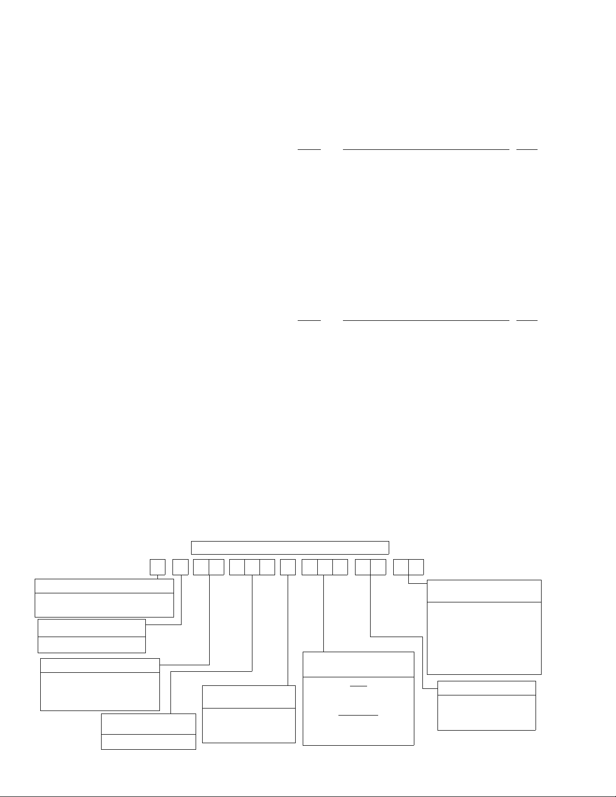
PRODUCT NOMENCLATURE
D 2 C G E C4N
PRODUCT CATEGORY
D = Single Package Air Conditioner
(Air Cooled)
PRODUCT GENERATION
2 = 2nd Generation
PRODUCT IDENTIFIER
CG = Gas/Electric
CE = Cooling only or
Electric / Electric
NOMINAL COOLING
CAPACITY
300 = 25 Tons
2 Unitary Products Group
FACTORY INSTALLED
HEAT
A = No Heat
N = Natural Gas
E = Electric
2 003 0 2 5
NOMINAL HEATING
OUTPUT CAPACITY
GAS
240 = 240 MBH
320 = 320 MBH
ELECTRIC
018 = 18 KW
036 = 36 KW
054 = 54 KW
072 = 72 KW
FACTORY INSTALLED
OPTION CODE
EC = Sing. Input Economiz er
DK = Diff. Input Economiz er
FD = Sing. Input Economizer
w/Power Exhaust
CF = Diff. Input Economizer
w/Power Exhaust
BG = Motorized Outdoor Air
Damper
VOLTAGE CODE
25 = 208/230-3-60
46 = 460-3-60
58 = 575-3-60
Page 3
INSTALLATION
LIMITATIONS
These units must be installed in accordance with the following
applicable national and local safety codes:
In U.S.A.:
1. Nati on al Elec trica l Cod e ANSI/ NFPA No. 70.
2. National Fuel Gas Code Z223.1.
3. Gas-Fired Central Furnace Standard ANSI Z21.47a.
4. Local gas and electric utility requirements.
In Canada:
1. Current Canadian Electrical Code C22.1.
2. Current Gas Installation Codes CAN/CGA-B149.1 and .2
3. Local plumbing and waste water codes.
4. Other applicable lo ca l co de s .
Refer to the Unit Application Data T able and to the Gas Heat Application
Data T ab le.
After installation, units with gas heat must be adjusted to obtain a
temperature rise within the range specified on the unit rating plate.
If components are to be added to a unit to meet local codes, they
are to be installed at the dealer’s and/or the customer’ s e xpense.
Size of unit for prop os ed in st al la ti on sh ou ld be ba se d on hea t
loss/heat g ain calcul ation made a ccording to the method s of
the Air Conditioning Contractors of America (ACCA).
This furnace is not to be used for temporary heating of buildings
or structures under construction.
TABLE 1
V oltage V ariation,
Min. / Max.
Supply Air CFM, Min. / Max. 8,000 / 12,000
Wet Bulb Temperature (°F) of Air on
Evaporator Coil, Min. / Max.
Dry Bulb T emperature (°F) of Air on
Condenser Coil, Min.
1
Utilization range “A” in accordance with ARI Standard 110.
2
A low ambient accessory is available for applica tio ns down to 0°F.
LOCATION
Use the following guidelines to sele ct a suitable location for
these units.
1. Unit is designed for outdoor installation only .
2. Condenser coils must have an unlimited supply of air.
3. For ground level installation, use a level concrete slab with
WARNING: Excessive exposure of this furnace to contami-
4. Roof structures must be able to support the weight of the
- UNIT APPLICATION DATA
208/230-3-60 187 / 253
1
Where a choice of location is possible, position the unit on
either north or east side of bu il di ng.
a minimum thickness of 4 inches. The length and width
should be at le ast 6 inc hes g rea ter t han the unit bas e ra ils .
Do not tie slab to the building foundation.
nated combus tion air may res ult in equipment d amage or personal injury. Typical contaminates include: permanent wave solutions, chlorinated
waxes and cleaners, chlorine based swimming
pool chemicals, water soft ening chemica ls, carbon
tetrachloride, Halogen type refrigerants, cleaning
solvents (e.g. perchloroethylene), printing inks,
paint removers, varnishes, hydrochloric acid, cements and glues, antistatic fabric softeners for
clothes dryers, ma sonry acid washing materials.
unit and its opti ons and/or accessori es. Unit must be installed on a solid level roof curb or appropriate angle iron
frame.
460-3-60 414 / 506
575-3-60 518 / 630
57 / 72
2
/ Max.
25 / 120
530.18-N11Y
CAUTION: If a unit is t o b e i ns tall ed on a ro of cu rb o r spec ia l
frame, gasketing mu st be applied to all surfaces
that come in contact with the unit underside.
5. Maintain lev el tole rance t o 1/2 " maximu m across the ent ire
length or width of the unit.
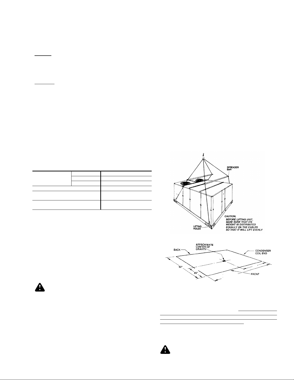
RIGGING AND HANDLING
Exercise care when moving the unit. Do not remove any
packaging until the unit is near the place of installation. Rig the
unit by attaching chain or cable slings to the round lifting holes
provided in t he base rails. Spreaders, wh ose length exceed s
the largest di mension ac ross the uni t,
be used acros s
MUST
the top of the unit.
Units may also be moved or lifted with a forklift, from the front
or rear only, providing that an accessory skid is used.
LENGTH OF FORKS MUST BE A MINIMUM OF 90".
CAUTION: On gas heating units, an adhesive backed label is
provided over the outside of the combustion air inlet
opening to prevent moisture from entering the unit
which could cause damage to electrical
components. Allow this closure label to remain in
place until the combustion air hood is to be
installed.
FIG. 1
- TYPICAL RIGGING
5
FIG. 2
- CENTER OF GRAVITY
4
136-1/4"
CLEARANCES
All units require certain clearances for proper operation and
service. Installer must make provisions for adequate combustion
and ventilation air in accordance with
Combustion and V entilation of the National Fuel Gas Code , ANSI
Z223.1 (in U.S.A.) or Sections 7.2, 7.3 or 7.4 of Gas Installation
Codes CAN/CGA-B149.1 and .2 (in Canada) and/or applicable
provisions of the local building codes. Refer to Dimensions and
Clearances table for the clearances required for combustible
construction, servicing, and proper unit operation.
WARNING:Do not permit o verhanging struct ure s or sh rubs to
obstruct ou tdoor air discharge ou tlet, combustion
air inlet or vent outlets.
Section 5.3, Air for
Unitary Products Group 3
Page 4
530.18-N11Y
DUCTWORK
Ductwork should be designed and sized according to the
methods in Manual Q of the Air Conditioning Contractors of
America (ACCA).
A closed return duct system shall be used. This shall not
preclude u se of ec onomizers or outd oor fres h air inta ke. The
supply and r eturn air duct connections at t he unit should be
made with flexible joints to minimize noise.
The supply and return air duct systems should be designed for
the CFM and static requirements of the job. They should
be sized to matc h the dime nsions of the duct connect ions on
the unit.
CAUTION: When fastening ductwork to side duct flanges on
unit, insert screws through duct flanges only. DO
NOT insert screws through casing.
Outdoor ductwork must be insulated and
waterproofed.
Refer to the Dimensions and Clearances figure for information
concerning side and bottom supply and return air duct openings.
It is recommended that, in Canada, the outlet duct on gas
heating units be provided with a removable access panel. It is
recommended that this opening be accessible when the unit
is installed in service, and of a size such that smoke or
reflected light may be observed inside the casing to indicate
the presence of leaks in the heat exchanger. The cover should
be attached in a ma nn er ad eq uate to preven t le ak ag e .
NOT
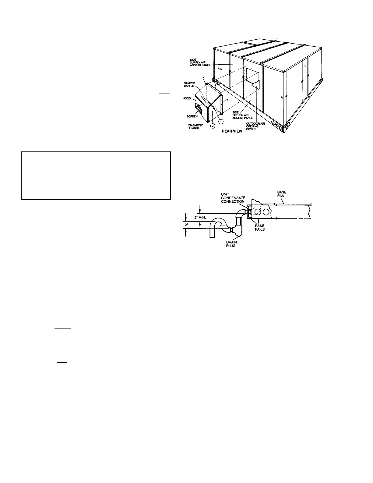
FIXED OUTDOOR AIR INTAKE DAMPER
FIG. 3
- FIXED OUTDOOR AIR DAMPER
CONDENSATE DRAIN
Plumbing must conform to local codes. Use a sealing
compound on male pipe threads. Install a condensate drain line
from the 1" NPT f emale connection on the unit to an op en drain.
This damper is shipped inside the return air compartment on units
that are not provided with an economizer or a motorized damper
option. It is completely assembled and ready for installation. A
damper baffle inside of the hood is adjustable to provide v ariable
amounts of outdoor air intake.
Gasketing and mounting screws are provided in a parts bag
attached to the hood assembly. Apply gasketing to the three
flange surfaces on the hood prior to installing the hood. Extend
gasketing 1/4" beyond the top and bottom of the two side
flanges to insure adequate sealing.
Adjusting the damper to the desired air flow may be done before
mounting the hood into position or (after installation) by
removing the front hood panel or the screen on the bottom of
the hood. Damper baffle in po siti on 1 will allow appr oximatel y
10% recirculated air f low , posit ion 2 appro ximatel y 15% and, to
allow approximately 25%, remove the damper baffle.
On units with
assembly o v er the o peni ng in the side retu rn air a ccess pane l.
Remove and discard the opening cover and the covering over
the hood moun ti ng h ol es (u se d for ship pi ng ) be fore inst al li ng .
Secure with the screws provided.
On units with side r eturn air appl ications, install th e damper
assembly on th e return air duc twork as close to the unit as
possible. Cut an opening 16" high by 18" wide in the ductwork
to accommodate the damper. Using the holes in the hood
flanges as a template, drill 9/64" dia. (#26 drill) holes into the
ductwork and secu re with the screws provide d.
CAUTION: If outdoor air intake will not be required on units
bottom return air appl icat ions , i nstall the d ampe r
with bottom return air applications, the damper
assembly s hould still be moun ted on the side return
air access panel, per the instructions above, to
insure mois ture is not drawn into the unit du ring
operation. The covering over the mounting holes
only need be removed. Do not remove the opening
cover.
FIG. 4 -
NOTE: The condensate drain line MUST be trapped to provide
RECOMMENDED DRAIN PIPING
proper drainage.
COMPRESSORS
Units are ship ped with comp ressor mounting s facto ry-adjusted
and ready for operation.
CAUTION: Do
Not loosen compressor moun ting bolts.
FILTERS
2" filters are su pplied with each uni t. Filt ers must alwa ys be installed
ahead of the evaporator coil and must be kept clean or replaced
with same size an d type. Dirty filters will redu ce the cap acity of t he
unit and will result in frosted coils or safety shutdown. Minimum filter
area and required si zes a re sho wn in t he Ph ysic al Dat a Table.
SERVICE ACCESS
Access to all serviceable components is provided by the
follo w in g rem o vable panels:
Compressor compartment
•
Electri c Heat compartment - DCE models
•
Gas Heat compartment (Two panels) - DCG models
•
Side Supply & Return Air compartments (Two panels)
•
Blower compartment (Three panels)
•
Main control box
•
Filter compartment
•
Outdoor Air compartment (Two panels)
•
Refer to th e Di mensio ns an d Cl eara nces fi gure for location of t hese
access panel s.
CAUTION: Make sure that all screws and panel latches are
replaced and properly positioned on the unit to
maintain an air-ti gh t se al.
4 Unitary Products Group
Page 5
530.18-N11Y
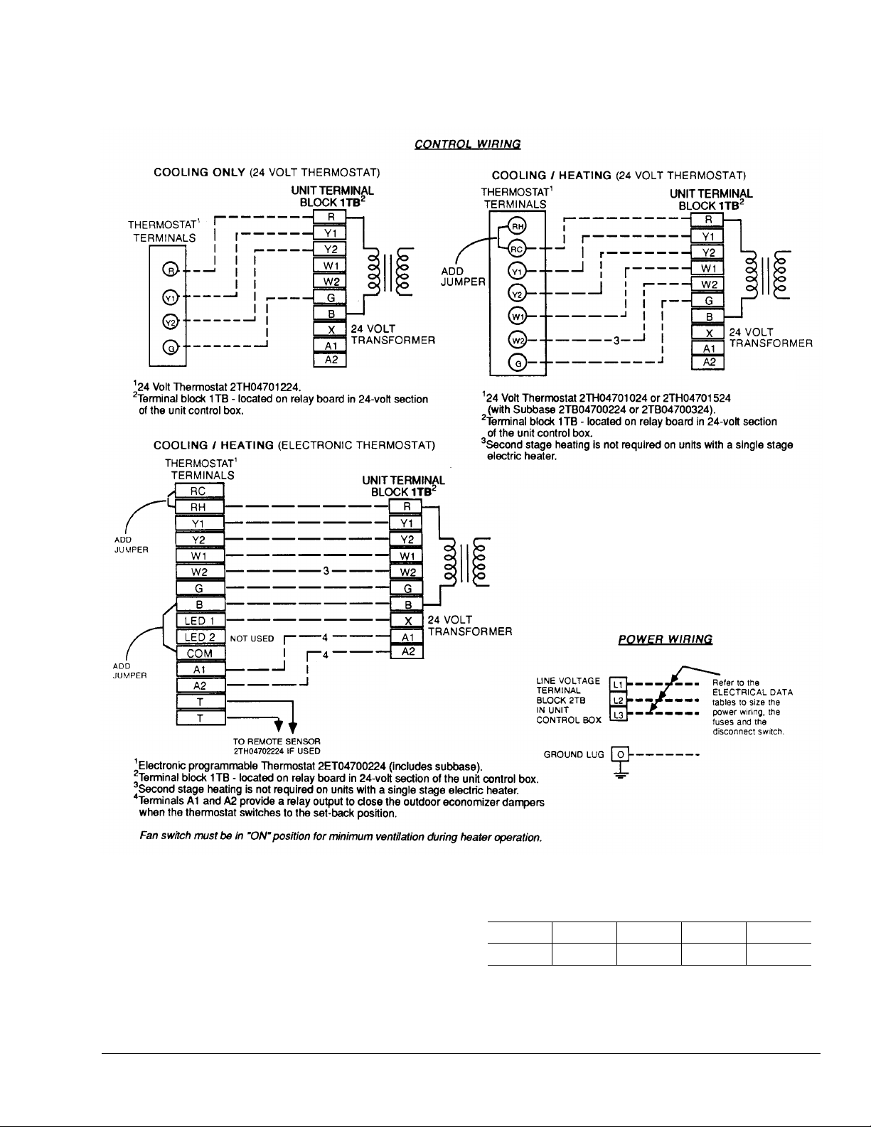
CONTROL WIRE SIZES
Wire Size1 AWG. Gauge
22 20 19 18 16
25 40 50 65 100
Maximum Wire Length2 Feet
Notes:
1. Solid, Class II copper wire
FIG. 5
- TYPICAL FIELD WIRING
Unitary Products Group 5
Page 6
530.18-N11Y
THERMOSTA T
The room thermostat should be located on an inside wall
approximately 56" above the floor where it will not be subject
to drafts, sun exposure or heat from electrical fixtures or
appliances. Follow manufacturer’s instructions enclosed with
thermostat for general installation procedure. Seven color
coded insulate d wires should be used to conn ect thermostat to
unit.
POWER AND CONTR OL WIRING
Field wiring to the unit must conform to provisions of the
National Electrical Code, ANSI / NFPA No. 70 (in U.S.A.),
current Cana dian Electrical Cod e C22.1 (in Canada) and/or
local ordinances. The unit must be electrically grounded in
accordance with NEC and CEC (as specified above) and/ or
local codes. Voltage tolerances which must be maintained at
the compressor terminals during starting and running
conditions are in dicated on the unit Ratin g Pla t e.
The internal wiring harness furnished with this unit is an integral
part of a ETL and CGA design certified unit. Field alteratio n to
comply with electrical codes should not be required.
A fused disconnect switch should be field provided for the unit.
The switch must be separate from all other circuits. Wire entry
at knockout openings require conduit fittings to comply with
NEC (in U.S.A.), CEC ( in Cana da) an d/or loc al co des. If any
of the wire suppl ied with the unit must be replaced, repla cement
wire must be of th e type shown on the wiring diagram and the
same minimum gauge as the replaced wire.
Electri cal line must be sized proper ly to carr y the load . Each
unit must be wired with a separate branch circuit fed directly
from the meter panel and properly fused.
CAUTION: When connecting electrical power and control
wiring to the unit, waterproof type connectors
MUST BE USED so that water or moisture cannot
be drawn into the unit during normal operat ion. The
above waterproofing conditions will also apply
when installing a field-supplied disconnect switch.
Refer to Typical Field Wiring Figure for typical field wiring and to
the appropriate unit wiring diagram for control circuit and power
wiring information.
OPTIONAL ELECTRIC HEATERS (DCE Models)
The factory installed heaters are wired for single point power
supply. Po wer supply need only be brought in to the singl e point
terminal block and thermostat w iring to the lo w volta ge terminal
block located in the upper portion of the unit control box.
These ETL an d CGA a pp roved he ater s ar e lo ca te d w ithi n th e
central compartment of the unit with the heater elements
extending into the supply air chamber. Refer to the Dimension
and Clearances figure for access panel location.
Fuses are supp li ed , whe r e req ui red , by the factory. Some KW
sizes require fuses and others do not. Refer to the Unit
Applicatio n Data Table 1 for minmum CFM limi tations an d to
Electrical Data T able.
TABLE 2
2,000 Feet
Sea Leve l
Max. Min. Max. Min. Max. Max. Min. Max.
300 150 270 135 240 213 279 20 50
400 200 360 180 320 281 372 30 60
NOTE: Heaters are shipped available for natural gas , but can be converted to
L.P. / Propane with Kit Model No. 1NP0418.
1
MBH rating should be red uce d at the ra te of 4 pe rce nt f o r ea ch 1, 000 feet above 4,500 feet.
2
Based on maximum input and 1075 Btu/Ft3.
3
The air flow must be adjusted to obtain a temperature rise within the range shown.
- GAS HEAT APPLICATION DATA
Input Capacity (Mbh) Output Capacity (Mbh)
0 T o
Above
2,000 To
4,500 Feet
Above
Sea Leve l
2,000 Feet
1
Sea Level
0 T o
Above
2,000 To
4,500 Feet
Above
Sea Leve l
1
Gas
Rate
(Ft.3/Hr.)
Temp.
2
Rise °F
At
Full Input
3
COMBUSTION DISCHARGE (DCG Models)
The products of combustion are discharged horizontally
through two screened (hooded) openings on the upper gas
heat access panel.
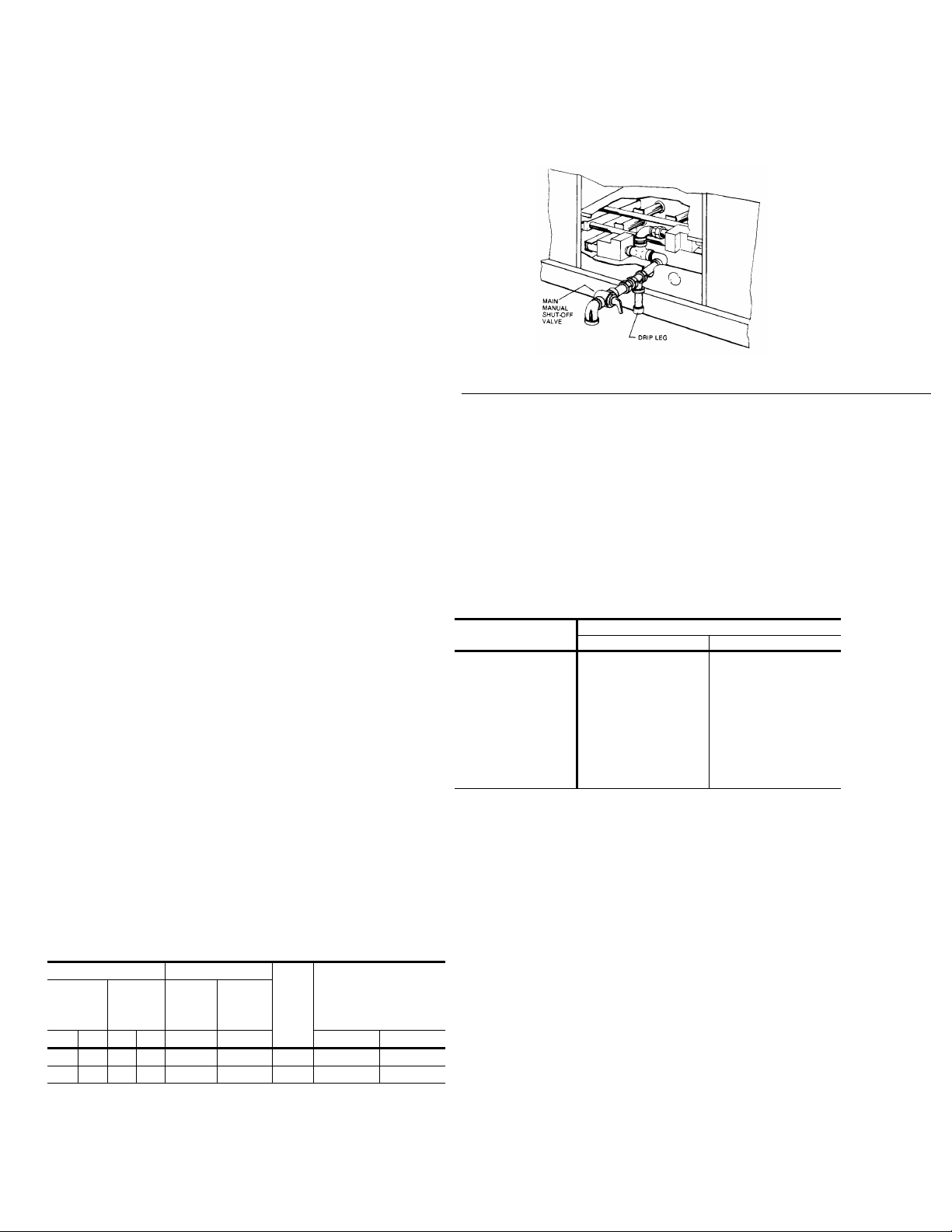
FIG. 6
- EXTERNAL SUPPLY CONNECTION
EXTERNAL SHUT-OFF
GAS PIPING (DCG Models)
Proper sizing of gas piping depends on the cubi c f eet pe r hour
of gas flow requir ed , sp ec ific gravity of th e ga s an d th e lengt h
of run. “National Fuel Gas Code” Z223.1 (in U.S.A.) or the
current Gas Installation Codes CAN/ CGA-B149.1 and .2 (in
Canada) should be followed in all cases unless superseded by
local codes or gas ut il ity requirements. See Pipe Sizin g t able.
The heating value of the gas may differ with locality. The value
should be chec ked with the local ga s ut ility.
NOTE : There may be a loca l gas utility requi rement specif ying
a minimum diameter for gas piping. All units re quire a
1 inch pipe connec ti on at th e entrance fitting.
TABLE 3
Maximum capacity of pipe in cubic feet of gas per hour. (Based upon a pressure drop of 0.3
inch water column and 0.6 specific gravity gas).
- PIPE SIZING
Length in Feet
10
20
30
40
50
60
70
80
90
100
Nominal Iron Pipe Size
1 in. 1-1/4 in.
520
350
285
245
215
195
180
170
160
150
1,050
730
590
500
440
400
370
350
320
305
GAS CONNECTION (DCG Models)
The gas supply line can be routed through the knockouts
located on the front of the unit or through the opening provided
in the unit’s base. Typical supply piping arrangements are
shown in the Supp ly C onn ecti on fi gures. All pipe, fitt ings, e tc.
are field-supplied.
T wo grommets are shipped in the blower compartment (in parts
bag taped to the blower housing) of every unit with gas heat
and should be used in the knockouts when the gas piping
enters through the front of the unit.
After the gas supply piping has been installed, the bottom
opening in t he unit should be sealed to prevent water fro m
leaking into the building.
Gas piping recommendations:
1. A drip leg and a ground joint union must b e installed in t he
gas piping.
2. When required by local co des, a man ual shut-of f val ve ma y
have to be in st al led outside of the unit.
3. U se w rough t ir on or st eel pipe for all ga s lines. Pipe compound should be ap plied sparingly to male thre ad s on ly.
6 Unitary Products Group
Page 7
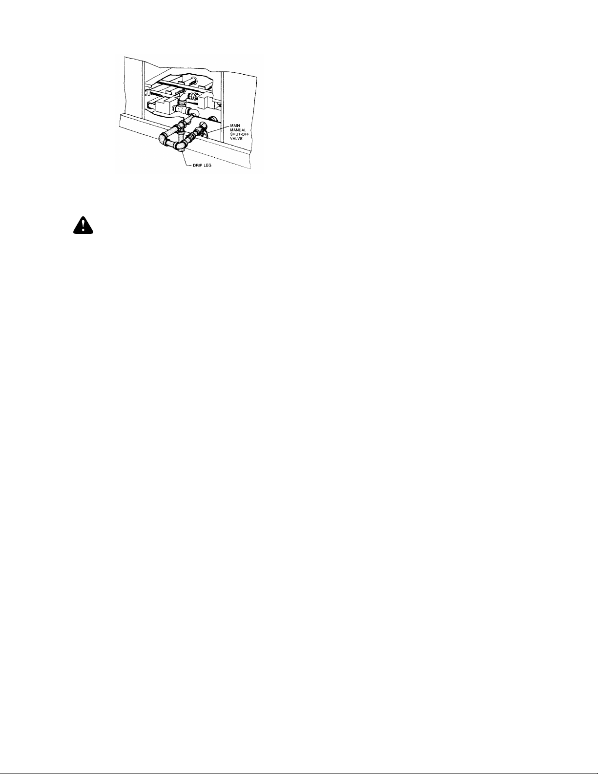
FIG. 7
- BOTTOM SUPPLY CONNECTION
EXTERNAL SHUT-OFF
WARNING:Natural gas may contain some propane. Propane,
being an excellent solvent, will quickly dissolve
white lead or most standard commercial
compounds. Therefore, a special pipe com pound
must be applied when wrought iron or steel pipe is
used. Shellac base compounds such as Gask olac
or Stalastic, and compounds such as Rectorseal
#5, Cyde’s or John Crane ma y be us ed.
4. All piping should be clea ned of dirt and scale b y hammering
on the outside of th e pipe and bl owing out the loose dirt and
scale. Before i nitial start-up , be sure t hat al l of t he ga s lin es
external to the un it have been purged of air.
5. The gas supply should be a separate line and installed in
accordance with all safety codes as prescribed under
“Limitations”. After the gas connections have been
completed, open the main shut-off valve admitting normal
gas pressure to the mains. Check all joints for leaks with
soap solution or other material suitable for the purpose.
NEVER USE A FLAME.
6. T he fur nac e and its indiv idual m anual sh ut-off valve must
be disconnect ed fro m t he ga s sup ply p ipin g syst em d uring
any pressure testing of that system at test pressures in
excess of 1/2 psig (3.48kPa).
The furnace must be isolated from the gas supply piping
system by closing its individual manual shut-off valve during
any pressure testing of the gas supply piping system at test
pressures equal to or less than 1/2 psig (3.48kPa).
7. A 1/8 inch NPT plugged tapping, accessible for test gage
connection, m ust be in st alle d imme dia tely upst ream o f t he
gas supply connection to the furnace.
530.18-N11Y
L.P. UNITS, TANKS AND PIPING (DCG Models)
All gas heat units are shipped from the factor y equipped for
natural gas use only. The unit may be converted in the field for
use with L.P./ propane gas with access ory kit model nu mber
1NP0418.
All L. P./propane gas equipment must conform to the safety
standards of the Nat io nal Fire Protection Association.
For satis factory operat ion, L.P ./propane gas pressure must be
8.8 inch W.C at the unit under full load. Maintainin g proper gas
pressure depends on three main factors:
1. The vaporization rate which depends on (a) the temperature of the li quid and (b) the “wetted sur face” area of the
container or containers.
2. The proper pressure regulation. (Two-stage regulation is
recommende d from the standpoint of both cost and efficiency.)
3. The pressure drop in the lines between regulators and
between the second stage regulator and the appliance.
Pipe size required will depend on the length of the pipe run
and the total load of al l ap pl iances.
Complete infor mation regarding tank sizing for vaporization,
recommended regulator settings, and pipe sizing is available
from most regulator manufacturers and L.P./propane gas
suppliers.
L.P./propane gas is an excellent solvent and special pipe
compound must be us ed w he n a ss em bling pi pi ng for this ga s
as it will quickly dissolve white lead or most standard
commercial compounds. Shellac base compounds such as
Rectorseal #5 are satisfactory for this type of gas.
Check all connections for leaks when piping is completed,
using a soap solution. NEVER USE A FLAME.
Unitary Products Group 7
Page 8
530.18-N11Y
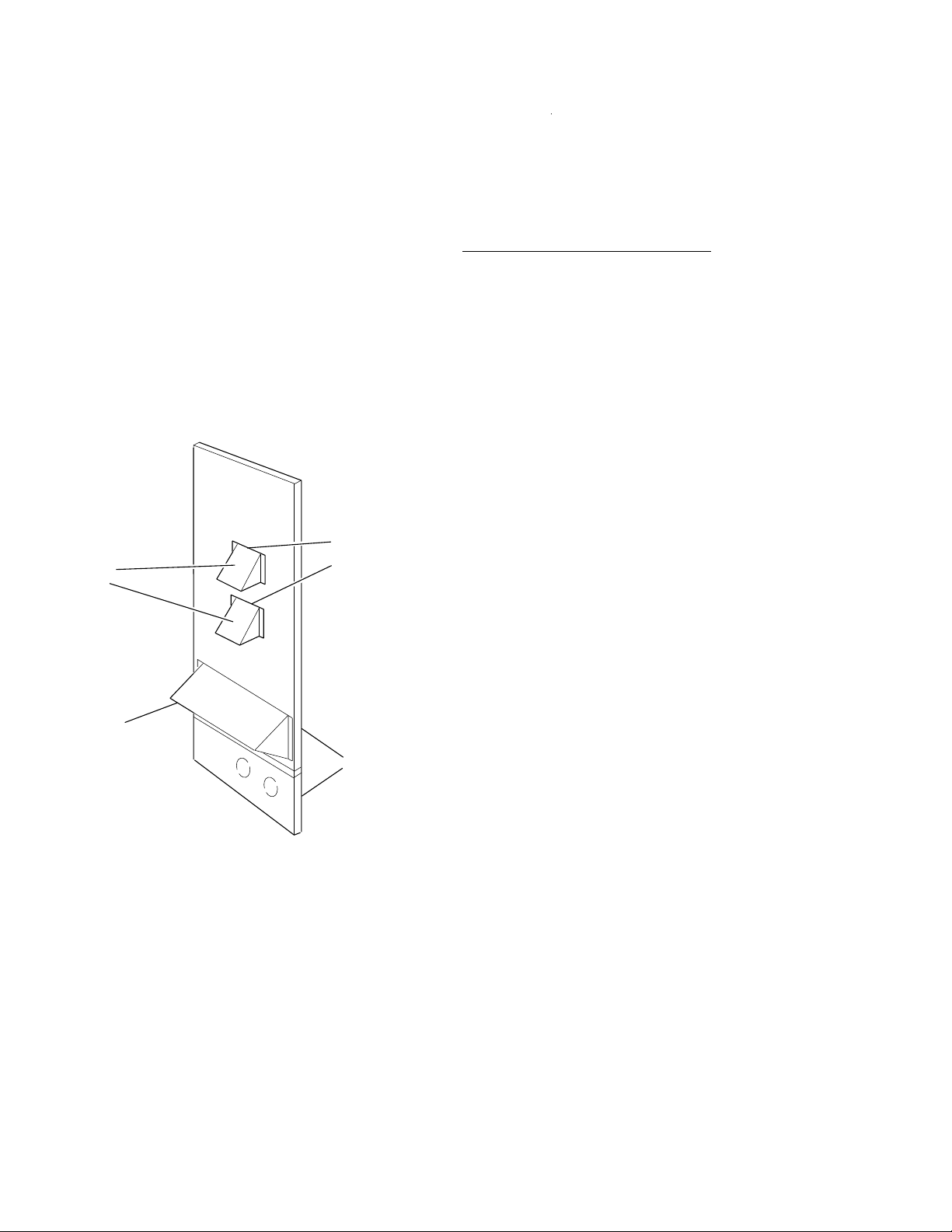
VENT AND COMBUSTION AIR HOODS
(DCG Models)
Two vent hoods and a combustion air hood (with screens) are
shipped attached to the blower housing in the blower
compartment. Thes e hoods must be ins talled to as sure pro per
unit function. All hoods must be fastened to the outside of the
gas heat access panel with the screws provided in the bag also
attached to the blower housing.
The screen f or the comb ustion air i ntake hood is secured to the
inside of the access panel op en in g w it h four fa st eners and the
screws used f or moun ting the hood t o the pane l. The top flange
of this hood s li ps i n under the top o f t he access panel o pe ning
when installing. Refer to the V ent and Combustion Hood figure.
OPTIONAL ECONOMIZER/MOTORIZED DAMPER
RAIN HOOD
The instru ction for the optional economizer/motorized damper
rain hood can be found in form 44-320-2. Use these instructions
when field a ssembling an econom izer rain hood ont o a unit.
The outdoor and return air damp ers, the damper actuator, the
damper linkage, the outdoor and return air divider baffles, and
all the control sensors are factory mounted as part of the
"Fac to ry install ed " ec on om izer option.
ENTHALPY SET POINT ADJUSTMENT
Remove the economizer access panel from the unit to check
the following adjustments. Loosen but do not remove the two
panel latches .
Each vent hood is installed by inserting the top flange of the
hood into the s lotted op ening i n the acce ss panel and sec uring
in place.
SLOTTED
VENT AIR
OUTLET
HOODS
COMBUSTION
AIR INTAKE
HOOD
OPENINGS IN
ACCESS PANEL
GAS HEAT
ACCESS
PANELS
CAUTI ON: Extreme care must be ex ercise d in turning both the
setpoint and m inimum p osition adjustin g scre ws to
prevent twisting them off.
1. T he enthalpy set point may now be set by selecting the
desired se tpoint shown in the Ent halpy figure. Adjust a s
follows:
For a single en thalpy operation, carefully turn the set
•
point adjusting screw to the “A”, “B”, “C” or “D” setting
corresponding t o th e le tt ere d cu rve.
For a dual enthalpy operation, carefully turn the set point
•
adjusting screw fully clockwise past the “D” setting.
2. To check that the damper blades m ove smoothly without
binding, carefully turn the minimum position adjusting
screw fully cl ockwise and then energize and de -energize
terminals “R” to “G”. With terminals “R” to “G” energized,
turn the minimum position screw counterclockwise until the
desired mini mum position has been attained.
3. Replace the economizer access panel. Reposition the two
latches horizontally and retighten the screws.
POWER EXHAUST/BAROMETRIC RE LIEF DAMPER
AND RAIN HOOD OPTION
The instructions for the power exhaust/barometric relief
damper and ra in hood can be found in form 44-320-10. The
exhaust fan, all supporting brackets, angles, and the wiring are
factory installed as part of the power exhaust option.
All of the components, including the dampers, hardware, and
mounting inst ructions are shipp ed in a single p ackag e e xternal
FIG. 8
- VENT AND COMBUSTION AIR HOODS
from the unit. The hood must be field a ssemble d and installe d.
Power exhaust is not available as a field installed option.
8 Unitary Products Group
Page 9

530.18-N11Y
FIG. 9
- ENTHALPY SETPOINT ADJUSTMENT
Unitary Products Group 9
Page 10

(1)
(
)
(
)
(
)
(
)
(
)
(
)
(
)
(
)
530.18-N11Y
TABLE 4
- PHYSICAL DATA
MODELS
EV APORATOR
BLOWER
EV APORATOR
COIL
CONDENSER
FAN
(Two Per Unit)
CONDENSER
COIL
COMPRESSOR
(Qty. Per Unit)
CENTRIFUGAL BLOWER (Dia. x Wd. in.) 18 x 15
F AN MOTOR HP 15
ROWS DEEP 4
FINS PER INCH 13.5
FACE AREA (Sq. Ft.) 25.0
PROPELLER DIA. (in.) (Each) 30
FA N MOTOR HP (Each) 1
NOM. CFM TOTAL (Each) 7200
ROWS DEEP 3
FINS PER INCH 15
FACE AREA (Sq. Ft.) 43.3
12.5-TON TANDEM 2
QUANTITY PER UNIT (16" X 20" X 2") 2
AIR
FIL TERS
QUANTITY PER UNIT (16" X 25" X 2") 4
QUANTITY PER UNIT (14" X 20" X 2") 3
TO TAL FACE AREA (sq. ft.) 21.4
CHARGE
This compressor will be energized first.
*
TABLE 5
REFRIGERANT
22 (lbs./oz.)
- ELECTRICAL DATA - BASIC UNITS
MODEL NO.
D2CE300 208/230-3-60 41.4 312 1 4.2 15 38.6 139.5 175
& D2CG300 460-3-60 20.0 140 1 2.1 15 19.3 68.3 80
DCE/DCG
300
OPERATING WEIGHTS (LBS.) 25 T ON
DCE (Cooling only) 2730
Basic Unit
DCG
(Gas /
Electric)
N240 2930
N320 2970
Economizer 160
Economizer with
Power Exhaust
Options
Motorized Damper 150
Electric
Heater
(DCE only)
18 KW 25
36 KW 30
54 KW 35
72 KW 40
Roof Curb 185
Barometric Damper 45
Economizer/Motorized
Accessories
Damper Rain Hood
Economizer/P o wer E xhaust
Rain Hood
SYSTEM NO. 1 20/8
Wood Skid 220
SYSTEM NO. 2 20/0
POWER
SUPP LY
COMPRESSORS
QTY. 2
COND. FAN
#1 & #2
RLA LRA HP FLA AMPACITY DEVICE
ea.
ea.
ea.
SUPPLY AIR MINIMUM MAXIM UM
BLOWER MOTOR
ea.
HP RLA
CIRCUIT OV ERCURRENT
AMPS
AMPS
575-3-60 16.4 108 1 2.0 15 15.4 56.1 70
245
55
90
TABLE 6
- ELECTRICAL DATA - UNITS w/ELECTRIC HEAT
MODEL POWER CIRCUIT OVERCURRENT
D2CE SUPPL Y AMPA CITY DEVIC E ( 1)
300A25 208-3-60 E018 13.5 1 37.5 139.5 175
300A25 208-3-60 E036 27.0 2 75.1 142.1 175
300A25 208-3-60 E054 40.6 2 112.6 189.0 200
300A25 208-3-60 E072 54.1 2 150.1 198.4 225
300A25 230-3-60 E018 18.0 1 43.3 139.5 175
300A25 230-3-60 E036 36.0 2 86.6 156.5 175
300A25 230-3-60 E054 54.0 2 129.9 178.2 200
300A25 230-3-60 E072 72.0 2 173.2 221.5 250
300A46 460-3-60 E018 18.0 1 21.7 68.3 80
300A46 460-3-60 E036 36.0 2 43.3 78.3 80
300A46 460-3-60 E054 54.0 2 65.0 89.1 100
300A46 460-3-60 E072 72.0 2 86.6 110.7 125
300A58 575-3-60 E018 18.0 1 17.3 56.1 70
300A58 575-3-60 E036 36.0 2 34.6 62.6 70
300A58 575-3-60 E054 54.0 2 52.0 71.2 80
300A58 575-3-60 E072 72.0 2 69.3 88.5 100
ELEC TRIC HEAT ER OPTION
MODEL kW(1) STAGES AMPS
MINIMUM MAXIMUM
(AMPS) (AMPS)
VOLT AGE
LIMITATIONS**
**
Utilization Range “A” in accordance with ARI Standard 110.
NOMINAL VOLT A GE VOL TAGE KW CAP . MULTIPLIER
POWER SUPPLY
208/230-3-60 187 253
460-3-60 414 506
575-3-60 518 630
208 208 1.00
240 230 0.92
480 460 0.92
600 575 0.92
MIN. MAX.
VOLT AGE
10 Unitary Products Group
Page 11

BLOW ER
BLOW ER MOTOR
ACCESS
BLOW ER
CO M PARTM ENT
ACCESS
(A u x ilia r y )
DOT PLUG
(F o r p re s s ure
Drop Reading)
ACCESS
FR O NT
VIEW
UNIT BASE W ITH RAILS
Show n separately to illustrate
Bottom D uct openings and P ow er
C onnection locations
NOTE:
For curb m ounted units, refer to the curb hanger
dim ensions of the curb for the proper size of the
s u p p ly a n d re tu r n a ir d u c t c o n n e c tio n s .
BLOW ER
ACCESS
FIELD-SUPPLIED
BLOW ER MOTOR
ACCESS
BLOW ER
CO M PARTM ENT
ACCESS
(A u x ilia ry )
DOT PLUG
(F o r p re s su re
Drop Reading)
GAS HEAT
ACCESS
VENT AIR
OUTLET
HOODS
COM BUSTION
AIR INLET
HOOD
(C )
GAS SUPPLY
ENTRY
DISCONNECT SW ITCH
LO C A TIO N
136-1/4
CONTROL BOX
ACCESS
FR O N T
VIEW
UNIT BASE W ITH RA ILS
Show n separately to illustrate
Bottom D uct openings, P ow er
and G as P iping C onnection
lo c a tio n s
NOTE:
For curb m ounted units, refer to the curb hanger
dim ensions of the curb for the proper size of the
s u p p ly a n d r e tu rn a ir d u c t c o n n e c tio n s .
(D )
GAS SUPPLY
ENTRY
FIELD-SUPPLIED
DISCONNECT SW ITCH
LO C A TIO N
136-1/4"
ELECTRIC HE AT
ACCESS
CONTROL BOX
ACCESS
6-3/8"
35"
35-1/4
33"
11-1/8"
46-5/8"
35"
35-1/4"
33"
21"
5"
7-1/8"
9-3/4"
5-7/8"
46-5/8"
RETURN
AIR
2-3/4" 21-1/2"
12-1/2"
E C O N O M IZ E R / M O T O R IZ E D D A M P E R ,
FIXED O UTDO O R IN TAKE AIR AND
POW ER EXH AUST RAIN HO O DS
(See detail "Y")
21"
5"
9-3/4"
5-7/8"
11-1/2"
RETURN
AIR
SUPPLY
2-3/4" 21-1/2"
9-1/4"
AIR
9-1/4"
12-1/2"
E C O N O M IZ E R / M O T O R IZ E D D A M P E R ,
FIXED O UTDO O R INTAKE AIR AND
POW ER EXH AUST RAIN HO O DS
(See detail "Y ")
92"
11-1/2"
BOTTOM SUPPLY
AND RETURN
AIR OPENING S
(See Note)
SUPPLY
AIR
8-1/8"
9-3/4"
92"
BOTTOM SUPPLY
AND RETURN
AIR O PEN ING S
(See N ote)
8-1/8"
9-3/4"
COM PRESSOR
ACCESS
(See detail "X ")
52-5/8
(A )
CONTROL W IRING
ENTRY
(B )
POW ER W IRING
ENTRY
3-3/4"
(B )
POW ER W IRING
ENTRY
(A )
CONTROL W IRING
ENTRY
COM PRESSOR
ACCESS
(See detail "X")
52-5/8"
CONDENSER
COILS
(A )
CONTROL W IRING
ENTRY
(B )
POW ER W IRING
ENTRY
3-3/4"
(B )
POW ER W IRING
ENTRY
(A )
CONTROL W IRING
ENTRY
OPTIONAL
COIL GUARD
CONDENSER
COILS
All dimensions are in inches. They are subject to change without notice. Cert ified dimensions will be provided upon request.
OPTIONAL
COIL GUARD
RETURN AIR
SUPPLY AIR
CONDENSER AIR
OUTDOOR AIR
(Economizer)
UTILITIES ENTRY DATA
HOLE
A
B
C 2-3/8" KO Gas Piping (Front)
D 1-11/16" Hol e Gas Piping (Bottom)*
Opening in the bottom of the unit can be located by the slice
*
in the insulation.
OPENING
SIZE
USED FOR
(DIA.)
1-1/8" KO
3/4" NPS (Fem.) B ottom
3-5/8" KO
3" NPS (Fem.) Bottom
Control
Wiring
Power
Wiring
CLEARANCES
Front 36"
Back
Left Side (Filter Access)
Right Side (Cond. Coil) 36"
Below Unit
Above Unit
1
Units (applicable in U.S .A. only) may be installed on combustible floo rs
made from wood or class A, B or C roof covering material.
2
Units must be installed oudo ors. Overhanging structu re s or shrubs sho uld
not obstruct condenser air discharge outlet.
3
If economizer is factory installed, the assembled hood kit must be removed
prior to final installation. This hood is 54" long.
NOTE:
DCE Models: Units and ductwork are appro v ed f o r ze ro cle arance to combustible materials when equipped with electric heaters.
DCG Models: A 1" clearance must be provided between any combustible
material an d the supply air ductwork for a distance of 3 feet from the un it.
The products of comb ust ion mu st no t be al lo we d to accum u lat e wi th in a
confined space and re ci rcu lat e .
Locate unit so that the vent air outlet hood is at least:
Three (3) feet above any forced a ir inlet loca ted within 10 horizontal feet
•
(excluding those integral to the unit).
Four (4) feet below, 4 horizontal feet from, or 1 foot above any door or gravity
•
air inlet into the building.
Four (4) feet from electric meters, gas meters, regulators and relief equip-
•
ment.
1
2
24" (Less Economizer)
49" (With Economizer)
24" (Less Economizer)
3
36"
(With Economizer)
20"
72" With 36" Maximum
Horizontal Overhang
(For Condenser Air
Discharge)
530.18-N11Y
Front
Front
Cont’d.
FIG. 10
Unitary Products Group 11
- DIMENSIONS & CLEARANCES - DCE & DCG
Page 12

530.18-N11Y
GAUGE LINE
ACCESS
40-3/8"
COMPRESSOR
ACCESS
SUPPLY AIR
ACCESS
5-1/2"
CONDENSER
SECTION
RETURN AIR
ACCESS
REAR
VIEW
SUPPLY
AIR
18-5/8"
5-1/8"
RETURN
AIR
27-3/4"
EVAPORATOR
SECTION
DUCT COVERS - Units are shipped with the bottom
duct openings covered. An accessory flange kit is avail-
DOT PLUG
(For pressure
drop reading)
able for connecting side ducts.
For
1. Remove the side panels from the supply and return
air compartments to gain access to the bottom
FILTER
ACCESS
supply and return air duct covers.
2. Remove and discard the bottom duct covers. (Duct
openings are closed with sheet metal covers except
when the unit includes a power exhaust option. T he
covering consists of a heavy black paper composition.)
OUTDOOR
AIR
40-1/2"
3. Replace the side supply and return air compartment
panels.
For
1. Replace the side panels on the supply and return air
compartments with the accessory flange kit panels.
2. Connect ductwork to the duct flanges on the rear of
the unit.
29-5/8" (15 TON)
39-5/8
39-5/8" (20 TON)
OUTDOOR AIR
COMPARTMENT
ACCESS
1" NPT FEMALE
COND. DRAIN
CONNECTION
DETAIL “X”
ACCESSORY SIDE SUPPLY AND RETURN AIR OPENINGS
bottom duct applications:
side duct applications;
FIG. 10
ECONOMIZER
SUPPLY AIR
COMPARTMENT
POWER
EXHAUST
RAIN
HOOD
Return Air Compartment)
(on
MOTORIZED
DAMPER
RAIN HOOD
(on Outdoor Air Compartment)
36"
66-1/2"
2"
34-1/4"
5"
ECONOMIZER
AND
REAR VIEW
DETAIL "Y"
UNIT WITH RAIN HOODS
DET AIL “Y”
UNIT WITH RAIN HOODS
- DIMENSIONS & CLEARANCES (Cont’d.)- DCE & DCG
MOTORIZED DAMPER
/
POWER EXHAUST RAIN HOODS
FIXED
OUTDOOR
HOOD
INTAKE
(located on
Return Air
Compartment)
16-1/8"
36-1/4"
AIR
92"
LH VIEW
1" CONDENSTATE
DRAIN
(Must be trapped)
12 Unitary Products Group
Page 13

(
g)
(
)
(kW)
(iwg)
(
)
(kW)
(iwg)
(
)
(kW)
(iwg)
(
)
(kW)
(iwg)
(
)
(kW)
g
y
530.18-N11Y
B
FIG. 11
A
D
FRONT
4 POINT LOADS
- FOUR AND SIX POINT LOADS
TABLE 7
- FOUR AND SIX POINT LOADS
UNIT
TOTAL A B C D
C
4 - POINT LOADS (LBS)
A
300 3,130 615 671 962 882
NOTE: These weights are with economizer, high heat, and the largest blower motor available.
UNIT
TOTAL A B C D E F
300 3,130 418 438 533 628 603 510
6 - POINT LOADS (LBS)
NOTE: These weights are with economizer, high heat, and the largest blower motor available.
F
FRONT
6 POINT LOADS
B
E
D
C
TABLE 8
BLOWER PULLEY
SPEED TURNS ESP OUTPUT INPUT ESP OUTPUT INPUT ESP OUTPUT INPUT ESP OUTPUT INPUT ESP OUTPUT INPUT
NOTES:
- SUPPLY AIR BLOWER PERFORMANCE
7500 CFM 8750 CFM 10000 CFM 11250 CFM
rpm)OPEN:(iw
975 6.0* 1.4 5.9 4.9 1.0 7.3 6.0 0.5 8.8 7.2 - - - - - -
1005 5.0 1.6 6.2 5.1 1.2 7.7 6.3 0.7 9.2 7.6 0.1 10.9 8.9 - - 1040 4.0 1.8 6.6 5.4 1.4 8.1 6.7 0.9 9.7 8.0 0.3 11.4 9.4 - - 1070 3.0 2.0 6.9 5.7 1.6 8.5 7.0 1.1 10.2 8.3 0.6 11.9 9.8 - - 1100 2.0 2.1 7.3 6.0 1.8 8.9 7.3 1.3 10.6 8.7 0.8 12.4 10.2 0.2 14.3 11.7
1135 1.0 2.4 7.7 6.3 2.0 9.3 7.6 1.6 11.1 9.1 1.0 13.0 10.6 0.4 14.9 12.2
1165 0.0 2.6 8.0 6.6 2.2 9.7 8.0 1.8 11.6 9.5 1.3 13.5 11.0 0.7 15.5 12.7
1140 6.0 2.4 7.7 6.3 2.1 9.4 7.7 1.6 11.2 9.2 1.1 13.1 10.7 0.5 15.0 12.3
1180 5.0 2.7 8.2 6.7 2.3 9.9 8.1 1.9 11.8 9.7 1.4 13.7 11.2 0.8 15.8 12.9
1215 4.0 2.9 8.6 7.0 2.6 10.4 8.5 2.2 12.3 10.1 1.7 14.3 11.7 1.1 16.4 13.5
1255 3.0 3.2 9.1 7.4 2.9 11.0 9.0 2.5 12.9 10.6 2.0 15.0 12.3 1.4 17.2 14.1
1290 2.0 3.4 9.5 7.8 3.1 11.5 9.4 2.7 13.5 11.1 2.2 15.6 12.8 - - 1330 1.0 3.7 10.0 8.2 3.4 12.0 9.9 3.0 14.1 11.6 2.6 16.4 13.4 - - 1365 0.0 3.9 10.5 8.6 3.7 12.6 10.3 3.3 14.7 12.1 2.9 17.0 13.9 - - -
Blower performance is based on co ol i ng only unit, with fixed outdoor air, 2" T/A filters and a dry evaporator coil.
Refer to pa
ESP - External Static Pressure available for the suppl
blower.
* FACTORY SETTING
e 14 for additional static resistances.
bhp
bhp
and return air duct system. All internal unit resistances have been deducted from the total static pressure of the
DCE300
STANDARD DRIVE:
ACCESSORY DRIVE:
- BOT TOM DUCT CO NNECTIONS
bhp
bhp
(
COOLI NG APPLICATIONS)
12500 CFM
bhp
Unitary Products Group 13
Page 14

(
)
(
)
(
)
(
)
(
)
(
(
(
(
)
(
g)
(
)
(kW)
(iwg)
(
)
(kW)
(iwg)
(
)
(kW)
(iwg)
(
)
(kW)
(iwg)
(
)
(kW)
g
y
530.18-N11Y
TABLE 9
- SUPPLY AIR BLOWER PERFORMANCE
BLOWER PULLEY
SPEED TURNS ESP OUTPUT INPUT ESP OUTPUT INPUT ESP OUTPUT INPUT ESP OUTPUT INPUT ESP OUTPUT INPUT
rpm)OPEN:(iw
975 6.0 1.2 5.9 4.9 0.5 7.3 6.0 - - - - - - - - 1005 5.0 1.4 6.2 5.1 0.7 7.7 6.3 - - - - - - - - 1040 4.0 1.6 6.6 5.4 0.9 8.1 6.7 0.2 9.7 8.0 - - - - - 1070 3.0 1.8 6.9 5.7 1.1 8.5 7.0 0.4 10.2 8.3 - - - - - 1100 2.0 2.0 7.3 6.0 1.3 8.9 7.3 0.6 10.6 8.7 - - - - - 1135 1.0 2.2 7.7 6.3 1.6 9.3 7.6 0.8 11.1 9.1 - - - - - 1165 0.0 2.4 8.0 6.6 1.8 9.7 8.0 1.0 11.6 9.5 0.2 13.5 11.0 - - -
1140 6.0 2.2 7.7 6.3 1.6 9.4 7.7 0.9 11.2 9.2 - - - - - 1180 5.0 2.5 8.2 6.7 1.9 9.9 8.1 1.2 11.8 9.7 0.3 13.7 11.2 - - 1215 4.0 2.7 8.6 7.0 2.1 10.4 8.5 1.4 12.3 10.1 0.6 14.3 11.7 - - 1255 3.0 3.0 9.1 7.4 2.4 11.0 9.0 1.7 12.9 10.6 0.9 15.0 12.3 - - 1290 2.0 3.2 9.5 7.8 2.7 11.5 9.4 2.0 13.5 11.1 1.2 15.6 12.8 - - 1330 1.0 3.5 10.0 8.2 3.0 12.0 9.9 2.3 14.1 11.6 1.5 16.4 13.4 - - 1365 0.0 3.7 10.5 8.6 3.2 12.6 10.3 2.6 14.7 12.1 1.8 17.0 13.9 - - -
NOTES:
Blower performance is based on cooling only unit, with fixed outdoor air, 2" T/A filters and a dry evaporator coil.
Refer to pa
ESP - External Static Pressure available for the suppl
blower.
* FACTORY SETTING
7500 CFM 8750 CFM 10000 CFM 11250 CFM 1 2500 CFM
bhp
e 14 for additional static resistances.
and return air duct system. All internal unit resistances have been deducted from the total static pressure of the
DCG300
bhp
-BOTTOM DUCT CONNECTIONS(COOLING APPLICATIONS)
STANDARD DRIVE:
ACCESSORY DRIVE:
bhp
bhp
bhp
TABLE 10
- STATIC RESISTANCES*
DESCRIPTION
7500 8750 10000 11250 12500
ESP ESP ESP ESP ESP
IWG
AIRFLOW
IWG
IWG
CFM
IWG
IWG
DEDUCTIO NS: ( SUBTRACT VALUES BELOW FROM UNIT'S AVAILABLE ESP)
ALLOWANCE FOR WET COIL: 0.10 0.10 0.10 0.10 0.10
ECONOMIZER
RETURN DUCT): 0.06 0.09 0.11 0.14 0.18
18kW ELECTRIC HEAT: 0.31 0.43 0.56 0.71 0.87
36kW ELECTRIC HEAT: 0.38 0.52 0.68 0.87 1.07
54kW ELECTRIC HEAT: 0.62 0.84 1.10 1.39 1.72
72kW ELECTRIC HEAT: 0.68 0.93 1.21 1.54 1.90
ADDI T I ONS: (ADD VALUES BELOW TO UNIT'S A V AILA BL E ESP)
HORIZONT AL
HORIZONT AL
TABLE 11
MOTOR
SPEED
SIDE) SUPPLY DUCT: 0.31 0.26 0.27 0.31 0.41
SIDE) RETURN DUCT: 0.05 0.05 0.05 0.05 0.05
- POWER EXHAUST PERFORMANCE
STATIC RESISTANCE OF RETURN DUCTWORK, IWG
0.20.30.40.50.6
CFM KW CFM KW CFM KW CFM KW CFM KW
HIGH* 5250 0.83 4500 0.85 4200 0.88 3750 0.93 3000 0.99
MEDIUM 4900 0.77 3900 0.79 3500 0.82 2900 0.85 - -
LOW 44000.7237000.7430000.78 - - - -
Factory Setting
*
Power Exhaust motor is a 3/4 HP, PSC type with sleeve bearings, a 48 frame and inherent protection.
TABLE 12
MODEL
SIZE
25 TON
1
All motors have a nominal speed of 1800 RPM, a 1.15 service factor and a solid base. They can operate to the limit of their service factor because they are located in the mov ing air, upstream
of any heating device.
- BLOWER MOTOR AND DRIVE DATA
1
BLOWER
MOTOR
DRIVE
Stan-
Speed
dard
High
RANGE
(RPM)
975/1165
HP FRAME
15 254T 91 1LVP58B70A 7.5
EFF.
(%)
1140/1365 1B5V94 9.7 9.5 1-7/16 5VX840 84.0 1
Access
ADJUSTABLE MOTOR PULLEY FIXED BLOWER PULLEY
DESIG-
NATION
OUTSIDE
DIA.
(IN.)
PITCH
DIA.
(IN.)
BORE
(IN.)
DESIG-
NATION
OUTSIDE
DIA.
(IN.)
PITCH
DIA.
(IN.)
1B5V110 11. 3 11.1 1-7/16 5VX860 86.0 1
6.2-
1-5/8
7.4
BORE
(IN.)
DESIGNATION
14 Unitary Products Group
BELT
(NOTCHED)
PITCH
LENGTH
(IN.)
QTY.
Page 15

OPERATION
COOLING SYSTEM
The cooling section is a complete factory package utilizing an
air-cooled condenser. The system is factory-charged with
Refrigerant-22.
The compresso rs are hermetically sealed, internally sp rung
and base-mounted with rubber-insulated hold-down bolts.
Compressors have inherent (internal) protection. If there is an
abnormal temperature rise in a compressor, the protector will
open to shut down the compressor.
PRELIMINARY OP ERATION COOLING
After the ini tial installa tion, the compres sors should be gi ven
three false starts (energized just long enough to make a few
revolutions) with 5-7 minutes delay between each start, before
being put into ful l ti me service .
COOLING SEQUENCE OF OPERATION
NO OUTDOOR AIR OPTIONS - When the room ther mostat
calls f or “first-stage” cooling, the low voltage control circuit from
“R” to “G” and “Y1" is completed to energiz e compressors #1/2
(50% capacity), condenser fan motor #1, and the supply air
blower motor (if the fan switch on the room thermostat is set in
the ”A U TO" position).
When the thermostat calls for “second-stage” cooling, the low
voltage con trol circui t from “R” to “Y2" is completed to energize
compressor #3/4.
After the thermostat is satisfied and opens, all components will
stop simultaneously. The blower motor will continue to operate
if the fan switch on the room thermostat is set in the “ON”
position.
ECONOMIZER WITH SINGLE ENTHALPY SENSOR - When
the room thermostat calls for “first-stage” cooling, the low
voltage control circuit from “R” to “G” and “Y1" is completed.
The ”R" to “G” circuit energizes the blower motor (if the fan
switch on the room thermostat is set in the “AUTO” position)
and drives the economizer dampers from fully closed to their
minimum positi on. If the enthalp y of the ou tdoor air is be low the
setpoint of the enthalpy controller (previously determined), “Y1"
energizes the economizer. The dampers will modulate to
maintain a constant supply air temperature as monitored by the
discharge air sensor. If the outdoor air enthalpy is above the
setpoint, ”Y1" energiz es compressors #1/2, and co ndenser f an
motor #1.
When the thermostat calls for “second-stage” cooling, the low
voltage control circuit from “R” to “Y2" is completed. If the
enthalp y of the outdoor ai r is below t he setpoi nt of the e nthalp y
controller ( i .e. first stage ha s e ne r gi zed the ec on om izer ) , ”Y2"
will energize compressors #1/2. If the outdoor air is above the
setpoint, “Y2" will energize compressor #3/4.
After the thermostat is satisfied and opens, all components will
stop simultaneously. The blower motor will continue to operate
if the fan switch on the room thermostat is set in the “ON”
position.
ECONOMIZER WITH DUAL ENTHALPY SENSORS - The
operation with the dual enthalpy sensors is identical to the
single sensor e xcept that a second ent halpy se nsor is mounted
in the retur n air. This return air sens or allows the economizer
to choose between outdoor air and return air, whichever has
the lowest enthalpy value, to provide maximum operating
efficiency.
ECONOMIZER (SINGLE OR DUAL) WITH POWER
EXHAUST - Thi s system op erates as specifie d abov e with o ne
530.18-N11Y
addition. The power exhaust motor is energized whenever the
economizer is chosen by the enthalpy sensor for first stage
cooling, “Y1". As always, the ”R" to “G” connection pr ovides
minimum position but does not provide power exhaust
operation.
MOTORIZED OUTDOOR AIR DAMPERS - This system
operation i s th e sa me a s th e un it s wi th no ou tdoo r ai r op ti on s
with one exception. When the “R” to “G” circuit is comp lete , the
motorized damp er driv es open to a po siti on s et b y the d ampe r
motor adjustment. When the “R” to “G” circuit i s opened, the
damper spring ret urns fu ll y cl os ed .
CONTINUOUS BLOWER - Continuous blower operation is
possible by closing the R to G circuit on the thermostat.
SAFETY CONTROLS
Each refrigerant system is equipped with the following safety
controls:
1. A Suction Line Freezestat to protect against low evaporator
temperatures due to a low air flow or a low return air
temperature. (Opens at 26°F + 5°F and resets at 38°F +
5°F)
2. A High Pressure Cutout Switc h to protect against excessiv e
discharge p ressu res due to a blocked conden ser c oil or a
condenser moto r failure. (Opens at 380 psig + 10 and rese ts
at 300 psig +10)
3. A Low Pressure Switch/Loss Of Charge to protect against
loss of refrigerant charge. (Opens at 7 psig + 3 and resets
at 22 psig + 5)
If either one of th e abo v e sa f et y cont rol s open s, that indi vidu al
refrigerant system will be locked out. The other refrigerant
system will con tinue in operat ion un less it too is e ff ected b y the
same fault. The lock out of either system can be reset by
opening the 24V circui t ei th er a t t he roo m t he rmostat or at the
unit disconnect.
ELECTRIC HEATING - SEQUENCE OF OPERATION
WITH POWER TO UNIT AND THERMOSTAT IN THE
HEATING MODE
Single-stage heating: (applies only to 18 KW heater, all other
heaters MUST use a two-s ta ge t he rmostat :)
a) If the fan switch is in the “ON” position, the evaporator
blower motor contactor (3M) will be energized through
terminal G to provide continuous blower operation. If the fan
switch is in the “AUTO” position, the blower will operate only
when there is a call for heating by the thermostat.
NOTE: All 240 & 480V heaters are provided with manual
reset backup protection limits. These will de-energize the heaters should the primary limit fail to open
or the contactors fail to open in a failure mode.
b) Upon a call f or h eat by the thermostat , the heater co ntactor
(6M) will be energized.
c) The thermostat will cycle the electric heat to satisfy the
heating requirem en ts of th e co nd it ioned space.
Two-stage heating: (applies to all heaters except 18 KW):
a) If the fan switch is in the “ON” position, the evaporator
blower motor contactor (3M) will be energized through
terminal G to provide continuous blower operation. If the fan
Unitary Products Group 15
Page 16

530.18-N11Y
switch is in the “AUTO” position, the blower will operate only
when there is a call for heating by the thermostat.
b) Upon a call for first-stage heat by the thermostat, the heater
contactor (6M) (6M & 7M on 72 KW, 240V) will be
energized.
If the second stage of heat is required, heater contactor
(7M) will be energized. Note that on the 54 KW, 240V
heater , heater contactors (7M & 8M) wi ll b e en erg ized and
on the 72 KW, 240V heater, heater contactors (8M & 9M)
TABLE 9
- HEAT ANTICIPATOR SETTING
HEATER
KW
18
36 0.29 0.29
54 0.29 0.58
72 0.58 0.58
18
36 0.29 0.29
54 0.29 0.29
72 0.29 0.29
18
36 0.29 0.29
54 0.29 0.29
72 0.29 0.29
VOLT AGE
208/230-3-60
460-3-60
575-3-60
SETTING, AMPS
TH1 TH2
0.29 -
0.29 -
0.29 -
will be energize d.
c) The thermostat will cycle the electric heat to satisfy the
heating requirem en ts of th e co nd it ioned space.
HEAT ANTICIPATOR SETPOINTS
It is important that the anticipator setpoint be correct. Too high of
a setting will result in longer heat cycles and a greater temperature
swing in the co nditioned space. Reducing the value below th e
correct setpoint will give shorter “ON” cy cles and ma y resul t in the
lowering of the te mpertur e withi n the co ndit ioned s pace. Refer to
the Heat Anticipator Setpoints table for the required .
GAS HEATING SEQUENCE OF OPERATION
The following sequence describes the operation of the gas heat
section.
CONTINUOUS BLOWER
With the room thermostat switch set to “ON”, the supply air
blower will operate cont inuousl y. The normally cl osed cont act
“K5-1" provides 24 volt po wer to the “3M” cont actor . The “3M-1,
2 & 3" power contact s clos e an d the blower motor operates.
INTERMITTENT BLOWER
With the room thermostat system switch set to the “AUTO” or “HEAT”
position and the fan switch set to “AUTO”, the supply air blower will
operate after the room thermostat calls for heat and the time delay
relay cl oses.
The “TH1" closes, the heat relay ”RW1" is energized. The “RW1-1”
power contact cl oses energizin g the line voltage draft moto r. Th e
“RW1-2" contact is also closed. As the speed of the draft motor
reaches ap proximatel y 2500 RPM, the centrif ugal switch contact
located on the end of the draft mot or shaft closes to power the first
stage ignition module “IC1”.
After a brief pre-purge time, ignition module “IC1" will start the first
stage ignitor sparking and will open the redundant valve located
inside the first st age main g as va lve “GV1” to allow a flow of gas to
only the first stage c arr yover tube. Only after the pilot flam e has
been ignited a nd th e p r es en ce of pi lo t flame detected at th e “IC1”
by a signal sent back through the flame sensor is sparking
terminated and the first stage mai n gas v alv e open ed.
Gas flows into each of the main burners and is ignited from
the carryover tube flame.
If “IC1” fails to detect a pilot flame, it will continue to try for a maximum
of 85 seconds to ignite the pilot tube. If the pilot flame is not detected,
then “IC1" will lock out furnace operation for 5 minutes, then retry
ignition sequence.
At the same time power was supplied to the “RW1”, a parallel
circuit activates “ETD” which closes the “ETD” contact after
approximately 35 seconds and energizes “K5" which closes
”K5-2" and starts the blow er by energizing “3M”.
When “TH2" closes, heat relay ”RW2" is energized. The
“RW2-1" contact is closed energizing the second stage ignition
module ”IC2". “IC2" will immediately start the second stage
ignitor sparking and will open the redundant valve located
inside the second stage main gas valve ”GV2" to allow a flow
of gas to the second sta ge carryo ver tube. Only after the pilot
flame has been ig nited and the presence of pi lot flame dete cted
at “IC2" by a signal sent back through the flame sensor is
sparking terminated and the main gas valve opened.
Gas flows into each of th e se cond stage main burn ers and i s
ignited from the carryo ver tube flame.
If “IC2" fails to detect a pilot fl ame, it will c ontinue to tr y for a
maximum of 85 seconds to ignite the pilot tube. If the pilot flame
is not detected, then ”IC2" will lock out furnace operation for 5
minutes, then retry ignition sequence. Note that the sec ond
stage furnace can operate even if first st age has locked out.
When the heating cycle is complete, “TH2" opens de-energizing
the ”RW2" then “TH1" opens de-energizing ”RW1" and “ETD”,
FIG. 12
REDUNDANT
VALVE
GAS MAIN
GAS
VALVE
TO PILOT BURNER
- GAS VALVE PIPING
MAIN VALVE
TO MAIN
BURNER
thus closing all gas valves. The blower motor will continue to
run (approximately 45 seconds after the furnace is shut down)
until “ETD” opens, de-energizing the “K5" relay and ”3M"
contactor. The draft motor will continue to run for a brief
post-purge cycle.
SAFETY CONTROLS
The control circuit includes the following safety controls:
1. Limit Control (LS). This control is located inside the heat exchanger
compartment and is set to open at the temperature indicated in
the Limit Control Setting Table. It resets automatically. The limit
switch operates when a high temperature condition, caused by
inadequate supply air flow occurs, thus shutting down the ignition
control and closing the main gas valves and energizing the blower .
2. Centrifugal Switch (CS). If the draft motor should fail, the
centrifugal switch attached to the shaft of the motor prevents
the ignition controls and gas valves from being energized.
3. Redundant Gas Valve. There are two separate gas valves
in the furnace. Eac h valv e cont ains a mai n and a red undant
valve. The red undant valves are loca ted upstream of th e
main gas valves. Should either or both of the main gas
valves fail in the open position the redundant valves serve
as back-ups and sh ut s off the flow of gas.
4. Flame Sensor Rod / 100% Ignition Control Lock-Out. If an
ignition cont rol fai ls to detec t a signal from the flame sen sor
indicating the pilot flame is properly ignited, then the main
gas valve will not open. It will continue to try and ignite the
pilot for a ma ximum of 85 secon ds, th en if the pilot f lame is
not detected, the ignition control will lock out furnace
operation until 24V power is removed from the module
either at the unit or by resetting the room thermostat.
5. Rollout Switch. This switch is located above the main burners in the control compartment which in the event of a
sustained ma in bur ner roll out sh uts of f and locks out both
ignition controls closing both gas valves. The ignition controls lock out furnace op eration un til 24V pow er is remov ed
from the controls either at the unit or by resetting the room
thermostat. Note th e auto reset rollou t switch must reset
before allowing furnace operation.
16 Unitary Products Group
Page 17

530.18-N11Y
FIG 13
IGN. CONTROL #2
IG N . C O N T R O L # 1
R O LLO U T S W .
SENSO R #1
GV2
GAS
VALVE
IG NITOR #2
BURNER COM PARTM ENT
-GAS VALVE AND CONTROLS
GV 1
GAS
VALVE
IG NITOR #1
SENSO R #2
TABLE 10
- LIMIT CONTROL SETTING
Capacity, MBH
Input Output
300 240 195
400 320 195
HEAT ANTICIPATOR SETPOINTS
It is important that th e an ti ci pa tor setpoint be correct. Too high of
a setting will result in longer heat cycles and a greater
temperature swing in the conditioned space. Reducing the value
below the correct setpoint will give shorter “ON” cycles a nd may
result in the lowering of the temper ture within the conditioned
space.
Gas Valve
Honeywell VR8440
White-Rodgers 36C68
Anticipator Setpoint
1st Stage 2nd Stage
0.30 amp 0.11 amp
PRE-START CHECK LIST
Complete the following checks before starting the unit.
1. C heck the type of gas being su pplied. Be sure that it is the
same as listed on the unit nameplate.
2. Make sure that the vent and combustion air hoods have been
properly instal le d.
START-UP
Limit Control
Opens, °F
6. Auxiliary Limit Switch (AUX) This control is located inside
the heat exchanger compartment and is set to open at
190°F. It is a manual reset switch. If A UX limit trips, then the
primary limit has not functioned correctly., Replace the
primary limit
OPERATING INSTRUCTIONS
CAUTION: This fur na ce i s eq uipp ed w ith an i ntermittent pilo t
and automatic re-i gnition sys tem. DO NO T att empt
to manually light the pilot.
TO LIGHT PILOT AND MAIN BURNERS:
1. Turn “off” electric power to unit.
2. Turn room thermostat to lowest sett ing.
3. Turn gas valve kn ob t o “on” position.
4. Turn “on” electric power to unit.
5. Set room thermostat to d esired temperature.
(If thermostat “set” temperature is above room temperature,
pilot burner ignition will occur and, after an interval to prove
pilot flame, main burners will ignite).
TO SHUT DOWN:
1. Turn “off” electric power to unit.
2. Depress knob of gas valve while t urning to “off” position.
POST-START CHECK LIST (GAS)
After the entire control circuit has been energized and the
heating section is operating, make the follo w in g ch ecks:
1. Check for gas le aks in the uni t pipi ng as wel l as t he supp ly
piping.
2. Check for correct manifold gas pressures. See “Checking
Gas Input”.
3. Check the supply gas pres sure. It m u st be w it hin the limits
shown on rating nameplate. Supply pressure should be
checked w ith all g as applia nces in the b uildi ng at f ull fire. At
no time should the standby gas line pressure exceed 13",
nor the operating pressur e drop below 5.0" for natural gas
units. If gas pressure is outside these limits, contact the
ON-OFF CONTROL
HIGH FIRE ADJ.
(UNDER SCREW)
PILOT ADJ.
(UNDER SCREW)
FIG. 14
- TYPICAL GAS VALVE
local gas utility for correctiv e action.
MANIFOLD GAS PRESSURE ADJUSTMENT
Small adjustments to the high-fire gas flow may be made by
turning the pressure regul ator adjusting scre w on the automatic
gas valve. Refer to figure below.
Adjust as follows:
1. Remove the cap on the regulator. It’s located next to the
push-on electrical terminals.
2. To decrease the gas pressure, turn the adjusting screw
counterclockwise.
Unitary Products Group 17
Page 18

530.18-N11Y
BURNER ASSEMBLY BRACKET
Reve rse the abo ve procedure t o replace the asse mblie s. M ake
sure that burners are level and seat at the rear of the heat
exchanger.
FLAME SENSOR BULB
1/8" GAP BETWEEN CARRY-OVER
TUBE AND FLAME SENSOR BULB
CARRY-OVER TUBE
FIG. 15
- PROPER FLAME ADJUSTMENT
3. To increase the gas pressure, turn the adjusting screw
clockwise.
NOTE: The correc t manifold pressure for these furnaces is
3.65 IWG ±0.3.
PILOT CHECKOUT
The pilot flame should envelope the end of the flame sensor . Refer
to Proper Flame Adjustment figure. To adjust pilot flame, (1)
remove pilot adjustment cover scre w, (2) increase or decrease the
clearance for air to the desired level, (3) be sure to replace cover
screw after adjustment to prevent possib le gas leakage.
Put the system into oper ation and ob serve th rough compl ete
cycle to be sure all co nt rol s fu nc ti on pr op erly.
BURNER AIR SHUTTER ADJUSTMENT
Adjust burn er shutters so no yellow fla me is obser ved in the
heat exchanger tubes.
CHECKING SUPPLY AIR CFM
The RPM of the supply air blower will depend on the required CFM,
the unit accessories or options and the static resistances of both
the supply and the return air duct systems. With this information,
the RPM for the supply air blower and the motor pulley adjustment
(turns open) can be deter mined from the Blower Performance
Data Table.
A high speed drive accessory 1LD0435 (containing a smaller
blower pulley and shorter belts) is available for applications
requiring the supply air blo wer to pro duce high er CFM’s and/or
higher static pressures. Refer to the Blower M otor and Drive
Data T able.
Note the following:
BURNER INSTRUCTIONS
To check or change burners, pilot or orifices, CLOSE MAIN
MANUAL SHUT-OFF V ALVE AND SHUT OFF ALL ELECTRIC
POWER T O THE UNIT.
1. R emove the screws holding ei ther end of the man ifold to
the burner supports.
2. Op en the un io n f itti ng in the g as su pp ly li ne ju st up str ea m
of the unit gas v alve an d downstream f rom the main manu al
shut-off valve.
3. Remove the gas pipi ng clo su re pa ne l.
4. Disconnect wiring to the gas valves and spark ignitors.
Remove the manifold-bur ner ga s valve assembly by lift in g
up and pulling back.
Burners are now accessible for service.
FIG.17 -
BELT ADJUSTMENT
1. The supply air CFM mus t be w ithin the l imitat ions s hown in
Unit Application DataTab le.
2. Pulleys can be adjusted in half turn increments.
3. The tension on the belts should be adjusted as shown in
the belt adjustmen t fi gu re be low.
Start the supply air blower motor. Adjust the resistances in both
the supply an d the retur n air du ct system s to balanc e the air
distribution throughout the conditioned space. The job
specifications may require that this balancing be done by
someone other tha n the equipment installe r.
T o check the supply air CFM after the initial balancing has been
completed:
FIG. 16
- TYPICAL FLAME APPEARANCE
18 Unitary Products Group
1. Remove the two 5/16 " dot plugs fro m the blo wer motor a nd
the filter access pan el s .
Page 19

2. Insert at least 8" of 1/4 inch tubing in to each of thes e holes
for sufficient pene tration into the air flow on both side s of
the indoor coil.
NOTE: The tubes must be inserted and held in a position
perpendicular to the air flow so that velocity pressure will not affect the static pressu re readings.
3. Using an inclined manometer, determine the pressure drop
across a dry evaporator coil. Since the moisture on an
evaporator coil may vary gr eatly, measuring the pressu re
drop across a wet coil under field conditions would be
inaccurat e. To assure a dry coil, the co mpres sors should
be deactivated while the test is being run.
4.Knowing the pressure drop across a dry coil, the actual CFM
through the unit and clean 2" filters, can be determined from
the curve in the Pressure Drop Verses Supply Air CFM
figure.
WARNI NG:Failure to prope rly adjust th e total syst em air quan -
530.18-N11Y
NOTE:
DE-ENERGIZE THE COMPRESSORS BEF ORE TAKING ANY TEST
MEASUREMENTS TO ASSURE A DRY INDOOR COIL.
ADJUSTMENT OF TEMPERATURE RISE
The temperature rise (or temperature difference between the
return air and the heated air from the furnace) must lie within the
range shown on the ETL rating plate.
After the te mperat ure r ise has been de ter mine d, the c fm can
be calculated as follows:
After about 20 minutes of operation, determine the furnace
temperature rise. Take readings of both the return air and the
heated air in the ducts (about six feet from the furnace) where they
will not be affected by radiant heat. Increase the blower cfm to
decrease the temperature rise; decrease the blower cfm to
increase the rise. Refer to the Blo wer Motor And Drive Data tab le.
BELT DRIVE BLOWER
All units have belt drive single-speed blower motors. The
variable pitch pu lley on the blower motor can be adjust ed to
obtain the desired supply air CFM. Tighten belts enough to
prev en t s li pp in g. but do not over ti gh te n. Belt deflection should
be between 1/4" and 1/2" per foot. Refer to the table for Blower
Motor And Drive Data.
CHECKING GAS INPUT
NATURAL GAS
FIG. 18 -
PRESSURE DROP ACROSS A DRY INDOOR
COIL VS SUP PLY AIR CF M
tity can result in extensive blower damage.
After readings have been obtained, remove the tubes and
reinstall th e two 5/16" dot plugs that were removed in Step 1.
CFM =
Btuh Input x 0.8
o
1.08 x
F Temp. Rise
1. Turn off all other gas appliances connected to the gas meter.
2. With the furnace turned on, measure the time needed for
one rev olution of t he hand on the smallest dia l on the met er.
A typical gas meter usually has a 1/2 or a 1 cubic foot test
dial.
3. Using the number of seconds for each revolution and the
size of the test dial increment, find the cubic feet of gas
consumed per hour from th e Gas Ra te Table.
TABLE 11
Example: By actual measurement, it takes 13 seconds for the hand on the 1-cubic
foot dial to make a revolution with just a 300,000 Btuh furnace running. Read
across to the column in the table above , headed “1 Cubic F oot”, where y ou will see
that 278 cubic feet of gas per hour are consumed by the furnace at that rate.
Multiply 278 x 1050 (the Btu rating of the gas obtained from the local gas company).
The result is 292,425 Btuh, which is close to the 300,000 Btuh rating of the furnace.
- GAS RATE - CUBIC FEET PER HOUR
Seconds
for One
Rev.
4
6
8
10
12
14
16
18
20
22
24
26
28
Size of Test Dial
1/2 cu. ft. 1 cu. ft.
450
300
228
180
150
129
113
100
90
82
75
69
64
900
600
450
360
300
257
225
200
180
164
150
138
129
SECURE OWNER’S APPRO VAL
: When the system is func ti oning properly, secure the owner’s ap proval. Show him the
location of all disconnect switches and the thermostat. Teach him how to start and stop the unit and how to adjust temperature
settings within the limitations of the system.
Unitary Products Group 19
Page 20

530.18-N11Y
MAINTENANCE
If the actual input is not within 5% of the furnace rating (with
allowance being made for the permissible range of the regulator
setting), replace the orifice spuds with spuds of the proper size.
NOTE To find the Btu input, multiply the number of cubic feet of
gas consumed per hour by the Btu content of the gas in
your particular locality (contact your gas company for this
information - it varies widely from city to city.)
NORMAL MAINTENANCE
CAUTION: Prior to any of the following maintenance proce-
dures, shut off all electric power to the unit to
prev en t pe rso na l in ju ry.
Periodic maintenance normally consists of changing or
cleaning filt ers and (u nder some c onditi ons) cle aning t he main
burners.
FILTERS - Inspect once a month. Replace disposable or clean
permanent type as necessary. DO NOT replace permanent
type with disposable. The dimensional size of the replacement
filter must be the same as the replaced filter.
MOTORS
Outdoor f an mo tors are p ermanently l ubricated and requ ire no
maintenance.
V entor motor is factory lubricated for an estimated 10 year
life.
Indoor Blower Motor and Drive - The indoor blower motor
features ball bea rin gs that do not req uire pe rio dic lubr ica tion.
Periodic lubrication of the motor and bearings can extend the
life of com po ne nt s but is optional.
CAUTION: Damage can occur if the bearings are overlubri-
cated. Use grease sparingly.
WARNING:P erform all maintenance op er at ions on the blower
motor with electric power disconnected from the
unit. Do not attempt to lubricate bearings with the
unit in operation.
On an annual basis, check the motor for accumulations of dust,
etc. that may block the cooling slots in the motor shell. Check for
loose, damaged or misaligned drive components. Check that all
mounting bolts are tight. Replace def ectiv e parts as required.
If desired, every three years remove both pipe plugs at each end
shell and clean out any hardened grease or foreign matter.
Replace one plug on each end with a clean grease fitting. Using
a low pressure grease gun, pump grease (Chevron SRI-2 or
equivalent) into the bearing cavity until new grease shows at the
open port. Do not over lubricate. Run the motor for ten minutes
until excess grease is purged from the cavity. Replace the plugs.
Units are supplie d with blower sh aft bearings that do no t require
maintenance but may be relubricated if desired. Every three
years, using a low pressure grease gun, pump grease into the
bearing grease fitting until grease j ust begins to s how at the
seals. Do not over lubricate. Use any lithium base grease
recommende d for ball bearing service.
OUTDOOR COIL - Dirt should not be allowed to accumulate
on the outdoor coil surface or other par ts in the air circuit.
Cleaning sh ould be as often a s nec es sar y to keep c oi l cle an.
Use a brush, vacuum cleaner attachment, or other suitable
means. If water is used to clean coil, be sure electric power to
the unit is shut off prior to cleaning.
NOTE: Exercise care when cleaning the coil so that the coil
fins are not damage d.
GAS HEATING UNITS
BURNER & PILOT - Periodically (at least annually at the
beginning of each heating season) make a visual check of the
pilot and main burner flame. If necessary, adjust main burner
primary air shutters to give a distinct, sharp blue flame as
explained under “BURNER AIR SHUTTER ADJUSTMENT”. If
it is not possibl e to adjust f or the proper fla me, the b urners may
need cleaning.
TO CLEAN BURNERS - Remove them from the furnace as
explained in “Burner Instructions”. Clean burners wi th hot water
applied along to p of the burner.
COMBUSTION AIR DISCHARGE - Visually inspect discharge
outlet periodical ly to make su re that the b uildup of soo t and dirt
is not excessive. If necessary, clean to maintain adequate
combustion air discharge.
CLEANING FLUE PASSAGES AND HEATING ELEMENTS
With proper combustion adjustment the heating element of a
gas fired fur nace will seldom need cleaning. If the element
should become so ot ed , it can be cleaned as fo llows:
1. Remove the burner assembly as outlined in “BURNER
INSTRUCTIONS”.
2. Remove the roof over the gas heat section.
3. At the top plate from the top draft blower housing and the
top draft blower wheel.
4. Remove the screws holding the top of the flue collector box.
Carefully remove the top of the flue collecto r box without
ripping the adjacent insulation. Then remove the center
divider plate separating the upper and lower flu e boxes.
5. On the inside of the flue collector box, remove the flue
baffles from the tube interiors. Note the last bend of the
baffle fits tigh tly against the tube forci ng the end of the baffle
to lock into t he tube collar. This collar is formed w hen the
tube is expanded into the end sheet. To remove, move the
end of the baffle toward the center of the tube releasing the
end of the baffle from the tube co llar, then pull straight out
of the tube.
6. Using a wire brush on a flexible wand, brush out the inside
of each heat e xchang er from the b urner inlet and fl ue outlet
ends.
7. Brush out the inside of the flue collector box and the flue
baffles.
8. Run the wire brush down the vent hoods from the flue
collector end.
9. I f soot buil d-up is par t icular ly b ad, remove the ven t motor
and clean the wheel and housin gs. Run the wire brush down
the flue extentions at the outlet of th e vent housings.
Do not per mit the hot co ndenser air dis charge to be
obstructed by overhanging structures of shrubs.
20 Unitary Products Group
FIG. 19
- TYPICAL FLUE BAFFLE INSTALLATION
Page 21

TROUBLESHOOTING
530.18-N11Y
10.After brushing is complete, blow all brushed areas with air
or nitrogen. Vacuum as need ed .
11.Replace parts in the order they were removed in Steps
1 thru 4.
12. When replacing the center and top of the flue collector box,
be careful not to tear the adjoining insulation.
13.Ensure that all seams on the vent side of the combustion
system are air tight. Apply a high temperature (+500°F)
sealing compound where needed.
WARNING:Troubleshooting of components necessarily re-
quires open ing the electr ica l contro l box with th e
power connected to the unit. Use extreme care
when working with live circuits! Check the unit
nameplate for the correct line voltage and set the
volt meter to the corr ect ra nge before maki ng any
connections with line terminals.
WARNING: Pr ior to any of the following maintenanc e proce-
dures, shut off all electric power to the unit to
prev en t pe rso na l in ju ry.
CAUTION: Label all wires prior to disconnection when servic-
ing controls. Wiring errors can cause improper and
dangerous oper at io n. Verify prop er operation afte r
servicing.
NOTE: To find the Btu input, multiply the n umber of cubic f eet of
gas consumed per hour by the Btu content of the gas in
your particular locality (contact your gas company for this
information - it varies widely from city to city.)
1. The indoor blower motor is a non-inherently protected
three-phase motor. Protection is provided by an overload
relay f or o v erc urrent a nd f uses for short circuit. I f th e mo tor
fails to run, check the line voltage circuit and control voltage
circuit per the following procedure:
a. If the Indoor Blower Motor does not operate, check
visually that contactor M3 is pulled in. If so, check for
line voltage betwee n al l th ree pha se s at the lin e terminals of the Blower Overload Relay (BOR). If line voltage
is found, check the l eads to th e blower mot or for open
circuit. If line voltage is found at the motor leads (inside
the conduit box on the motor shell), disconnect the
motor and check f or open windin gs per the motor wiring
diagram. If open windings are found, replace the motor.
If line voltage is not found at th e BOR , trac e the lead s
back to the field supp ly terminal block, check ing for an
open circuit or blown fuses.
b. I f the contactor M3 is not pul led in, check for control
voltage (24V) at the M3 coil. If voltage is found, replace
the contactor . If control v oltage is not f ound at M 3, check
for voltage across terminals 95 & 96 of the BOR. If
voltage exists, the BOR is open on overload. The BOR
should be set to the auto reset position. The BOR must
cool down in order to reset. If the BOR will not reset,
replace the BOR. If the BOR resets and M3 pulls in, but
the indoor blower moto r wi ll sti ll not r un, refer to para .
(a) for troubleshooting the line voltage supply circuit. If
control vol tage is not f ound at the BOR, trace the circuit
back to the relay board and thermostat per the unit
wiring diagram. Replace any defective components.
2. Draft motor operates and furnace lights but supply air
blower does not start after a short time delay with room
thermostat fan switch set to “AUTO”.
a. Set fan switch to “ON”. If blower motor runs, go to Step f.
If it does not, check to see if line voltage is being
supplied to the contac ts of the contactor (M3), and if the
contactor is pulled in. Check for loose wiring.
b. If contactor (M3) is pulled in, proceed with the trou-
bleshooting steps indicated in Step 1 above.
c. If (M3) is pulled in and the blower motor still does not
run, repl ace the blower motor.
d. If (M3) is not pulled in, check for 24 volts at the (M3) coil.
If 24 volts is pres en t, repl ac e th e (M3 ) contactor.
e. If 24 volts is not present at the (M3) coil, check for loose
24 volt wiring back to the relay board. Check control
wiring to the room thermostat. If all is fine, replace the
relay board .
f. If the blower motor runs with the fan switch in the “ON”
position but does not run soon after the furnace has
ignited with the f an s witch in the “AUTO” position, check
for loose 24 volt wirin g between th e relay board in the
main control box, the Mate-N-Lok connector in the
partition between th e e vap orator and gas hea t sectio ns
and the time delay relay (ETD).
g. If all control wiring is fine , check fo r 24 vo lts at th e rela y
board. If 24 volts is present, replace the relay board. If
24 volts is not present, replace the (ETD) relay.
NOTE: The furna ce may sh ut itsel f down on a hig h temp era-
ture conditio n during the proc edure, but this will not
effect the test if it is done within 5 minutes of furnace
shut-down.
3. The supply air blower operates but the draft motor does not
when the room the rmostat is set to c all f or he at an d the f an
switch in the “ON” posi ti on .
a. The draft motor has inherent protection. If the motor shell
is hot to the touch, wait for the internal overload to reset.
b. If the moto r shell is cold wi th the room the rmostat calling
for heat, check for line voltage at the motor’s Mate-N-
Lok conne ctor attached to the evaporator partition . If
line voltage is present, replac e the draft motor.
c. If line voltage is not present, chec k for li ne voltag e at the
heat relay (RW1) contacts in th e main contro l box and
check to see if the (RW1) is pulled in.
d. If the (RW1) relay is pulled in, check for a loose line
voltage co nn ec ti on.
e. If the (RW1) relay is no t pu ll ed in, c heck for 24 volts at
the (RW1) coil. If 24 volts is present, replace the (RW1)
relay. If 24 volts is not present, check for a loose 24 volt
connection back to the relay board and check the connections from t he room t hermostat to th e rela y board. If
all connections are correct, replace the relay board.
Cont’d.
Unitary Products Group 21
Page 22

530.18-N11Y
TROUBLESHOOTING
4. The draft motor runs but the furnace does not light and the
sparker does not sp ark.
a. The ignition control (IC1, IC2 ) may be loc ked ou t due to
either a fla me roll out or 100% s hut off. These safety
features are described above. If lock-out has occurred,
24V must be remov ed from the igniti on cont rols. This is
done at the unit or by resetting the room thermostat.
After resetting 2 4V, check fo r proper f urnace oper atio n.
If lock-out continues to occur, locate the source of the
problem and co rrec t.
b. Check all 24 volt connections from the relay board to
and in the gas hea t sect ion. Check low vo ltage connec tions to the (ETD) located in the control box.
c. If the furnace is hot, it may be out on an over-tempera-
ture condition, wait for limit reset.
d. If the furnace is cold, check for 24 volts at wire 241
attached to the electronic time delay (ETD) located in
the main control box. If 24 volts is not found, replace the
ETD.
e. With the draft motor running, check for 24 volts at
terminal 4 of (RW1-2) and (RW2-1). If 24 volts is not
present, the centrifugal switch (CS) has not closed or
has gone bad. Check the li ne v olt age to t he unit - if it is
correct, replace th e draft motor . If line voltage i s low , call
the power compan y.
- Cont’d.
d. If 24 volts is present, remove the pilot burner and
remove the pi lot orifice fr om the pilot b urner . T he orifice
is removed in the direction opposite the flow of gas.
Inspect the o rific e for obstruc tion. If it is clear, replace
the main gas valve.
6. The sparker sparks at the p ilot b urner but the pilo t does n ot
ignite and a gas odor is detected at the draft motor outlet.
a. Adjust the pilot adjust screw on the gas valve as de-
scribed in “PILOT CHECKOUT”.
b. Check the supply pressure as described in “POST
ST ART CHECK L IST”. Mak e adjustment s as necessary .
c. Check the pilot orifice for obstruction as described in
para. 5d. Clean as needed but the problem should not
be the gas valve.
7. The pilot burner ignites but the sparker continues to spark
and the main bu rners do not ignite.
a. Make the same chec ks and ad justme nt as desc ribed in
para. 6.
b. Make sure that the pil ot b urner is not be nt or damage d.
c. Make sure that the ground connections at the pilot
burner, gas valve and ignitor control are intact. Check
the high tension wire for good electrical connection. If
all are intact, replac e th e ig ni tor module.
f. Check for 24V at terminal 2 of (RW1-2 and RW2-1). If
24V is not present, check for 24V at (RW1 and RW2)
relay coils. If these relays are pulled in, then check for
a loose connec tion at terminal 2 an d terminal 4 of each
relay. If no problem is found, then replace (RW1 and/or
RW2) as require d.
g. I f 24 volts is presen t at the ignitor cont rols, check all
control wiring at the ignitor controls and the high tension
wire to the ignitors. Check that the ground wires from
the ignitor controls , the gas v alves and pilot b urners are
all intact a nd mak ing go od ele ctrical conn ection . Check
to make sure that the ceramic insulator on the pilot
ignitors or sensors is not broken or cracked, if all are
intact, replace the ignition control IC1 or IC2.
5. The draft motor runs and the sparker sparks at the pilot
burner but the pilot does not ignite and a gas odor is
detected at the dr aft motor outlet.
a. C heck to make sur e gas is be ing supplied to the unit.
Make sure that the gas pressure to the unit is within the
proper limits as describe d in the “POST START CHECK
LIST” and that the pilot adjust scr ew is allowing s ome
flow of gas as described in “PILOT CHECKOUT”.
b. Check all wiring between the ignitor control and the gas
valve. Check to make sure the ground connections are
intact.
c. If the wiring is in tact, chec k f or 24 vo lts across terminals
“PV” and “COMMON” on the ign itor c ontro l. If 24 volts
is not present, replace the ignitor control.
not
8. The pilot burner lights and the spark stops but the main
burners do not light.
a. C heck electr ical c onnectio ns betwee n the igni tor con-
trol and the gas v alve . If intact , check f or 24 v olts acro ss
terminals “MV” and “COMMON” terminals. If no voltage
detected, replace ignitor control. If voltage is present,
replace gas valve.
9. Furnace lights with roll-out or one burner has delayed
ignition.
a. Make sure that the pilot b u rner is al ig ne d p r op erly w i th
the carryover as described in “PILOT CHECKOUT”.
b. Make sure that the carryov ers on adj oining b urners are
screwed fast and are level with respect to one another.
10. Main burners light but exhibit erratic flame characteristics.
a. Adjust air shutters as described in “BURNER AIR
SHUTTER ADJUSTMENT”.
b. Check the main burner orifices for obstruction and
alignment. Removal procedure is described in
“BURNER INSTRUCTIONS”. Clean or re place bur ner
orifices and burners as needed.
22 Unitary Products Group
Page 23

530.18-N11Y
REPLACEMENT PARTS
COMPRESSOR SECTION
Hermetic compressor
•
Compressor mounti ng
•
MOTOR SECTION
Blower motor
•
Fan motor
•
Ventor motor
•
ELECTRICAL SECTION
Ignition control
•
Relay board
•
Contactor
•
Circuit breaker
•
Temperature controls
•
Capacitors
•
Relays
•
Transformers
•
Connectors
•
TO OBTAIN PARTS INFORM ATION: Replacem ent pa rts and in form at io n fro m OU R c urr e nt parts lis t for this unit are available to
your servicing contractor through our local distributor. The name and address of our nearest distributor may be obtained by
consulting the Yellow Pages of a local tele phon e direc tory.
IMPORTANT:
complete model number listed on the rating plate located on your unit. See page 2 for Product Nomenclature.
WARNING: IMPROPER INSTALLA TION, ADJUSTMENT, SERVICE OR MAINTENANCE CAN CA USE INJUR Y OR PR OPERTY
DAMA GE. CONSUL T A Q UAL IFIED INSTALLER, SERVICE A GENCY OR YOUR LOCAL GAS SUPPLIER FOR INFORMA TION
OR ASSISTANCE.
In order to supply the correct part or information from the parts list, our distributor will need to be provided with the
GAS HEAT SECTION
Heat exchanger
•
Gas valve
•
Pilot
•
Flame sensor
•
Spark ignitor
•
Gas manifold
•
Gas burner
•
AIR MO VING SECTION
Blower wheel
•
Blower wheel housing
•
REFRIGERANT SECTION
Evaporat or co il
•
Evaporat or co il hea der
•
Expansion valve assembl y
•
Condenser coil
•
Condenser coil header
•
FABRICATED PARTS SECTION
Panels
•
Posts
•
Covers Drain pans
•
Base rails
•
Air hoods
•
MISCELLANEOUS SECTION
Air inlet hood screen
•
Fan gu ard
•
Air filters
•
Unitary Products Group 23
Page 24

Unitary Products Group
5005 York Drive, Norman, Oklahoma 73069
Subject to change without notice. Printed in U.S.A.
Copyright by York International Corporation 1999. All Rights Reserved.
Code: SBY
530.18-N11Y
 Loading...