

Page 1
TECHNICAL GUIDE
AFFINITY
SPLIT-SYSTEM AIR CONDITIONERS
13 SEER – R-410A
MODELS:
CZB018 THRU 060
(1.5 THRU 5 NOMINAL TONS
LISTED
Due to continuous product improvement, specific ations
are subject to change without notice.
Visit us on the web at www.york.com
Additional rating information can be found at
www.ari.org/aridirectory
)
ISO 9001
Certified Quality
Management System
246723-YTG-J-1006
DESCRIPTION
The CZB Series condensing unit is the outdoor part of a versatile air conditioning system. It is designed to be custom matched
with one of our complete line of evaporator sections, each
designed to serve a specific function. Matching air handlers are
available for upflow, downflow, and horizontal left or right application to provide a complete system. Electric heaters are available if required. Add-on coils are available for use with upflow,
downflow, or horizontal furnaces. Field installed accessories are
available as needed.
WARRANTY
5-year limited parts warranty.
10-year limited compressor warranty.
FEATURES
• Superior Coil Protection – A stamped decorative metal coil
guard completely protects coil from debris and other large
damaging material while a polymer mesh further protects the
coil against smaller particles.
• Color Grilles - Engineered around the needs and wants of
the consumer, Af fi nity unit s are now a vailab le wi th a ch oice of
color options designed to compliment any home.
• Isolated Compressor Compartment – A molded composite
bulkhead isolates the compressor from the rest of the unit
reducing sound and vibration.
• Protected Compressors – Each compressor is protected
against abnormal pressures by an internal pressure relief
valve and factory installed high and low pressure controls.
Additional protection against moisture and debris is provided
by factory installed liquid line filter driers.
• Environmentally Friendly Refrigerant – Next generation
refrigerant R-410A delivers environmentally friendly performance with zero ozone depletion.
• Durable Finish – Automotive quality finish provides the ultimate protection from harmful U.V. rays and rust creep ensuring long-lasting high quality appearance. A powder-paint
topcoat is applied over a baked-on primer, using a galvanized, zinc coated steel base material. The result is a finish
that has been proven in testing to provide 33% greater durability than conventional powder-coat finishes.
• Lower Installed Cost – Designed to provide enhanced
installability by featuring a slide-down control compartment
and angled service valves to reduce overall installation time
and cost.
• Low Operating Sound Levels – A fan design boasting technology adapted from aeronautic and defense engineering
provides for whisper quiet operation by allowing airflow to
flow smoothly and efficiently across the fan ti ps.
• Filter-Drier – A factory installed, solid core liquid line filterdrier filters harmful debris and moisture from the system.
• Easy Service Access – A full end, full service, access panel
with handle makes for easy entry to internal components.
• Composite Base - Strong and durable composite base pan
resists rust and corrosion while it helps reduce vibrations and
noise.
• Quiet drive system - Features combination of swept-wing
fan, composite base pan, isolated compressor compartment
and two-stage compressor to reduce overall sound to a mere
whisper.
• Low RPM fan motor - Helps to reduce airflow noise.
Certified in accordance with the Unitary Small Equipment certification program, which is based on ARI Standard 210/240.
FOR DISTRIBUTION USE ONLY - NOT TO BE USED AT POINT OF RETAIL SALE
Page 2
246723-YTG-J-1006
PHYSICAL AND ELECTRICAL DATA
MODEL CZB01811 CZB02411 CZB03011 CZB03611 CZB04211 CZB04811 CZB06011
Unit Supply Voltage 208-230V, 1φ, 60Hz
Normal Voltage Range
Minimum Circuit Ampacity 13.3 16.5 18.9 22.3 28.7 27.9 34.4
Max. Overcurrent Device Amps
Min. Overcurrent Device Amps
Compressor Type Scroll Scroll Scroll Scroll Scroll Scroll Scroll
Compressor Amps
Crankcase Heater No No No No No No No
Fan Motor Amps Rated Load 0.5 0.5 0.5 1.5 1.5 1.5 1.5
Fan Diameter Inches 22 22 22 22 22 22 22
Fan Motor
Coil
Liquid Line Set OD (Field Installed) 3/8 3/8 3/8 3/8 3/8 3/8 3/8
Vapor Line Set OD (Field Installed) 3/4 3/4 3/4 3/4 7/8 7/8 7/8
Unit Charge (Lbs. - Oz.)
Charge Per Foot, Oz. 0.62 0.62 0.62 0.62 0.67 0.67 0.67
Operating Weight Lbs. 165 170 190 190 205 215 260
1 Rated in accordance with ARI Standard 110, utilization range “A”.
2 Dual element fuses or HACR circuit breaker. Maximum allowable overcurrent protection.
3 Dual element fuses or HACR circuit breaker. Minimum recommended overcurrent protection.
4 The Unit Charge is correct for the outdoor unit, matched indoor coil and 15 feet of refrigerant tubing. For tubing lengths other than
15 feet, add or subtract the amount of refrigerant, using the difference in length multiplied by the per foot value.
1
2
3
20 25 30 35 50 45 60
15 20 20 25 30 30 35
187 to 252
Rated Load 10.3 14.3 16.4 16.6 21.8 21.1 26.3
Locked Rotor 51 60 73 88 105 113 150
Rated HP 1/15 1/15 1/15 1/4 1/4 1/4 1/4
Nominal RPM 850 850 850 850 850 850 850
Nominal CFM 2100 2,250 2,300 3,200 3,250 3,500 3,500
Face Area Sq. Ft. 14.86 14.86 17.15 17.15 20.58 20.58 20.58
Rows Deep 1111112
Fins / Inch 22 22 22 22 22 22 22
4
5-13 6-4 7-4 6-4 8-13 8-12 13-9
VAPOR
LIQUID
2-3/8
3-1/8
6-1/2
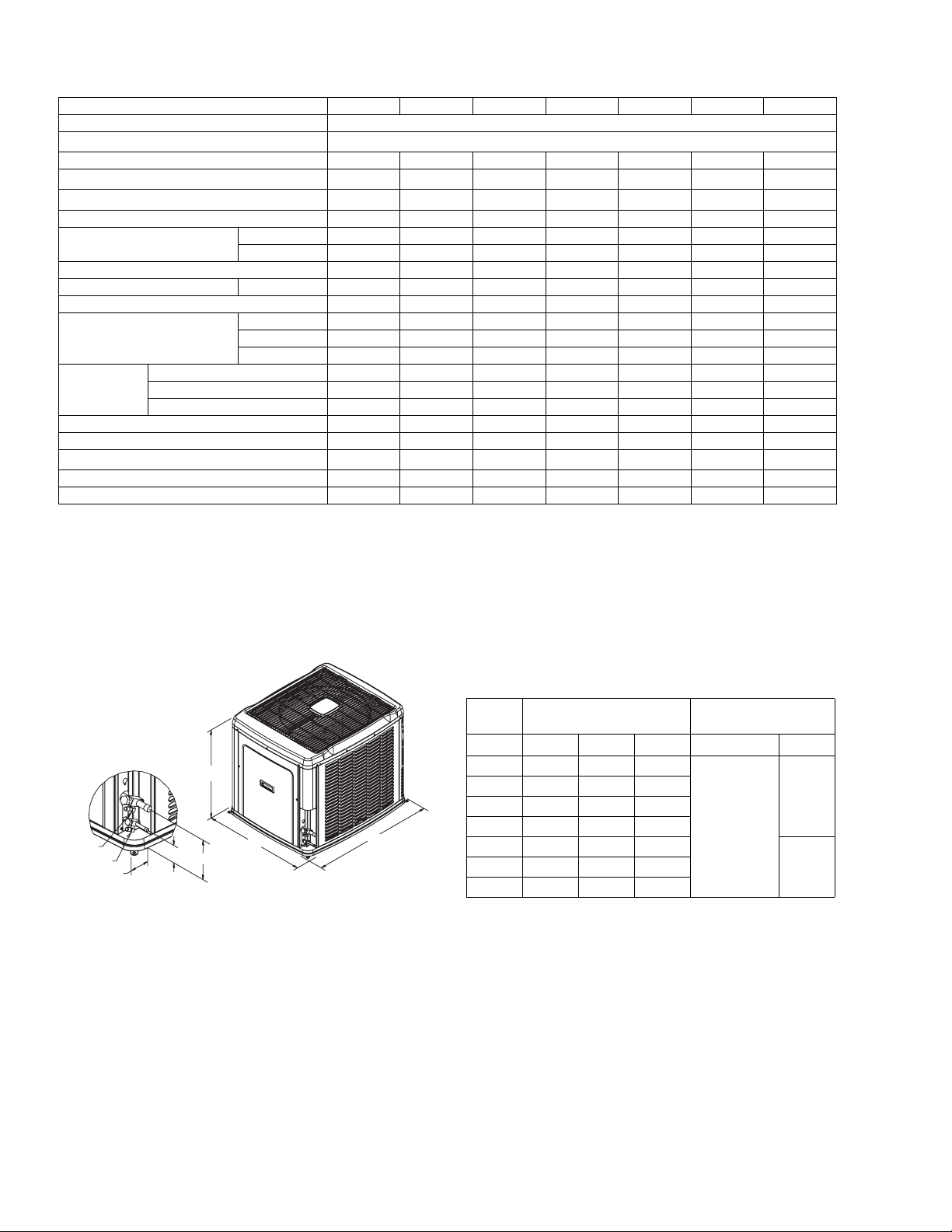
All dimensions are in inches. They are subject to change without
notice. Certified dimensions will be provided upon request.
DIMENSIONS
Unit
Model
A
018 29-1/2 37 31
024 29-1/2 37 31
030 33-1/2 37 31
C
B
036 33-1/2 37 31
042 39-1/2 37 31
060 39-1/2 37 31
Dimensions
(Inches)
Refrigerant Connection
Service Valve Size
A B C Liquid Vapor
3/4”
3/8”
7/8”048 39-1/2 37 31
2 Unitary Products Group
Page 3
246723-YTG-J-1006
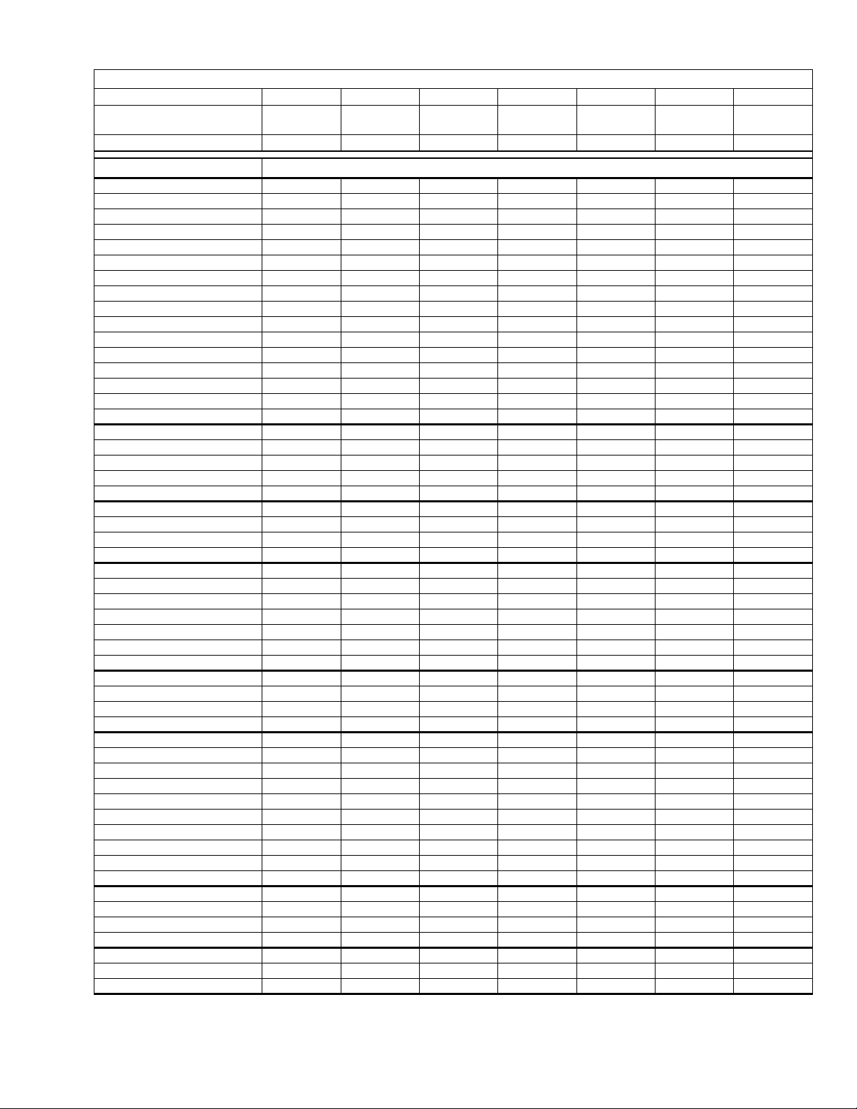
Additional R-410A Charge / TXV Size for Various Matched Systems
Outdoor Unit
Unit Orifice (s)
Factory R-410A Charge, lbs-oz
Indoor Coil
FC/MC/PC/UC18A3X 5––––––
FC/MC/PC/UC18B3X 5––––––
FC/MC/PC/UC24A3X 56–––––
FC/MC/PC/UC24B3X 56–––––
FC/MC/PC/UC30A3X 563––––
FC/MC/PC/UC30B3X 563––––
FC/MC/PC/UC36A3X ––33–––
FC/MC/PC/UC36B3X ––33–––
FC/MC/PC/UC36C3X ––33–––
FC/MC/PC/UC42B3X –––3–––
FC/MC/PC/UC42C3X –––3–––
FC/MC/PC/UC48C3X –––– 6––
FC/MC/PC/UC48D3X ––––6––
FC/PC/UC60C3X –––––124
FC/MC/PC/UC60D3X –––––124
MC61D3X ––––––4
HC18A3X 5––––––
HC30A3X –6–––––
HC36B3X ––33–––
HC42C3X –––––––
HC60D3X ––––6124
HD24A3X –––––––
HD36B3X ––33–––
HD48C3X ––––6––
HD60D3X –––––124
AHP18B3X 5––––––
AHP24B3X 56–––––
AHP30B3X ––3––––
AHP36C3X ––33–––
AHP42C3X –––3–––
AHP/SHP48D3X ––––612–
AHP/SHP60D3X ––––6124
AV24B3X 56–––––
AV36C3X ––33–––
AV/SV48D3X ––––6124
AV/SV60D3X ––––6124
G2FD024(S,H)14,17 5 – –––––
G2FD030(S,H)17 563––––
G2FD035(S,H)14 563––––
G2FD036(S,H)17 5633–––
G2FD036(S,H)21 ––33–––
G2FD042(S,H)21 ––33–––
G2FD046(S,H)17 ––33–––
G2FD048(S,H)21,24 –––36––
G2FD060(S,H)24 –––––12 4
G2FD061H24 –––––12 4
G1HA024H14 56–––––
G1HA036H14 5––3–––
G1HA036H17 5 6 3 3–––
G1HA060H24 –––––124
G1HD024 56–––––
G1HD036 ––33–––
G1HD060 ––––––4
For Notes See Page 4
1,2
CZB01811 CZB02411 CZB03011 CZB03611 CZB04211 CZB04811 CZB06011
1TVM901 1TVM903 1TVM903 1TVM903
5-13 6-4 7-4 6-4 8-13 8-12 13-9
Additional Charge, Oz
1TVM904
1TVM4C1
1TVM905 1TVM905
Unitary Products Group 3
Page 4
246723-YTG-J-1006
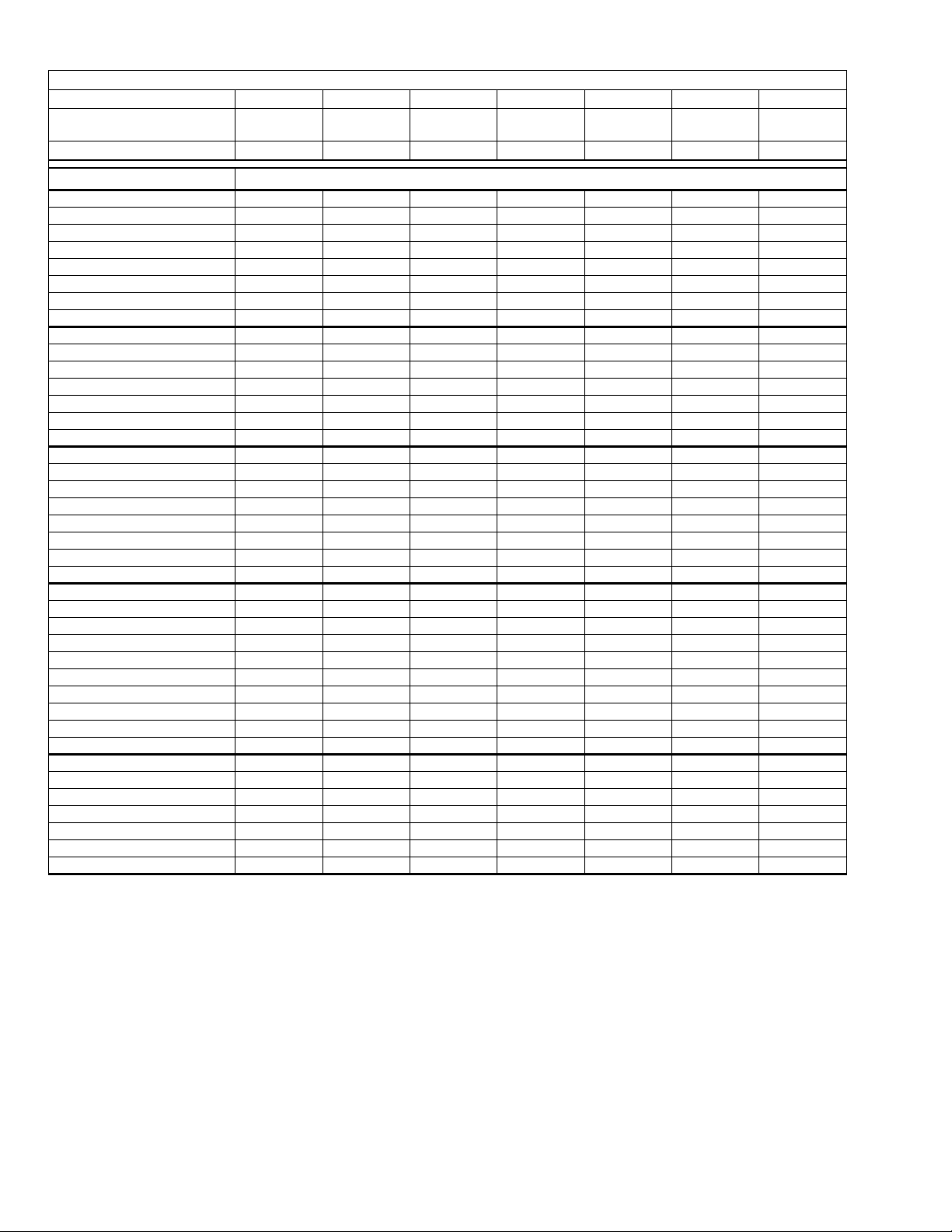
Additional R-410A Charge / TXV Size for Various Matched Systems
Outdoor Unit
Unit Orifice (s)
Factory R-410A Charge, lbs-oz
Indoor Coil
G1NA030S17K 563––––
G1NA030S21M 563––––
G1NA036S17J 563––––
G1NA036S21C 563––––
G1NA036S17L –––3–––
G1NA042S24W ––––6––
G1NA048S21D –––3–––
G1NA060S24T ––––612–
G1FA/G1UA024S14,17 5––––––
G1FA/G1UA030S14 5–3––––
G1FA/G1UA036S14 563––––
G1FA/G1UA036S17,21 563––––
G1FA/G1UA048S17 ––33–––
G1FA/G1UA048S21 ––33–––
G1FA/G1UA060S21,24 ––––6124
F*RP024/F*FP024 5––––––
F*RP030/F*FP030 –63––––
F*RP036/F*FP036 ––33–––
F*RP042/F*FP042 –––3–––
F*RP045/F*FP045 ––––6––
F*FP048 ––––6––
F*FP060 –––––––
F*FV060 –––––124
G4FD024H14,17 5––––––
G4FD030H17 563––––
G4FD035H14 563––––
G4FD036H17 5633–––
G4FD036H21 ––33–––
G4FD042H21 ––33–––
G4FD046H17 ––33–––
G4FD048H21,24 –––36––
G4FD060H24 –––––124
G4FD061H24 –––––124
G4FA024S14,17 5––––––
G4FA030S14 5––––––
G4FA036S14 563––––
G4FA036S17,21 563––––
G4FA048S17 ––33–––
G4FA048S21 ––33–––
G4FA060S21,24 ––––6124
FOOTNOTES:
PROCEDURES:
1,2
1 Systems matched with furnace or air handlers not equipped with blower-off delays may require blower Time Delay Kit 2FD06700224.
2 PC coils cannot be used in downflow or horizontal applications. FC coils cannot be used in horizontal applications.
1. Unit factory charge listed on the unit nameplate includes refrigerant for the condenser, the smallest evaporator and 15 feet of interconnecting line tubing.
2. Verify the TXV and additional charge required for specific evaporator coil in the system using the above table.
3. Additional charge for the amount of interconnecting line tubing greater than 15 feet at the rate specified in the Physical and Electrical Data Table.
4. Permanently mark the unit nameplate with the total system charge. Total System Charge = Base Charge (as shipped) + adder for
evaporator + adder for line set.
CZB01811 CZB02411 CZB03011 CZB03611 CZB04211 CZB04811 CZB06011
1TVM901 1TVM903 1TVM903 1TVM903
5-13 6-4 7-4 6-4 8-13 8-12 13-9
Additional Charge, Oz
1TVM904
1TVM4C1
1TVM905 1TVM905
4 Unitary Products Group
Page 5
COOLING CAPACITY - With Air Handler Coils
UNIT
MODEL
CZB01811
CZB02411
CZB03011
CZB03611
CZB04211
CZB04811
CZB06011
CZB01811
CZB02411
CZB03011
CZB03611
CZB04211
CZB04811
CZB06011
For Notes See Page 6.
MODEL
MA08B 2,5,8,10 17 FC/MC18B 600 18.0 12.1 13.00 11.00
MA08B 2,5,8,10 17 FC/MC24B 600 18.0 12.1 13.00 11.00
MA08B 2,5,8,10 17 FC/MC30B 600 18.0 12.1 13.00 11.00
MA08B 2,5,8,10 17 G*FD024H17 600 18.0 12.1 13.00 11.00
MA08B 2,5,8,10 17 G*FD030H17 600 18.0 12.1 13.00 11.00
MA08B 2,5,8,10 17 FC/MC24B 800 23.2 16.9 13.00 11.00
MA08B 2,5,8,10 17 FC/MC30B 800 23.2 16.9 13.00 11.00
MA08B 2,5,8,10 17 G*FD030H17 800 23.0 16.7 13.00 11.00
MA08B 2,5,8,10 17 G*FD036H17 800 23.4 17.0 13.00 11.00
MA12B 5,8,10,15,19 17 FC/MC30B 1000 29.8 21.7 13.00 11.00
MA12B 5,8,10,15,19 17 FC/MC36B 1000 30.0 21.9 13.00 11.00
MA12B 5,8,10,15,19 17 G*FD030H17 1000 29.4 21.5 13.00 11.00
MA12B 5,8,10,15,19 17 G*FD036H17 1000 30.0 21.9 13.00 11.00
MA12B 5,8,10,15,19 17 G*FD046H17 1000 30.0 21.9 13.00 11.00
MA12B 5,8,10,15,19 17 FC/MC36B 1200 35.6 26.3 13.00 11.00
MA12B 5,8,10,15,19 17 FC/MC42B 1200 36.0 26.5 13.00 11.00
MA12B 5,8,10,15,19 17 G*FD036H17 1200 35.6 26.3 13.00 11.00
MA12B 5,8,10,15,19 17 G*FD046H17 1200 36.0 26.5 13.00 11.00
MA14D 5,8,10,15,19 24 G*FD048H24 1200 36.0 26.5 13.00 11.00
MA16C 5,8,10,15,20 21 FC/MC48C 1400 41.0 30.2 13.00 11.00
MA14D 5,8,10,15,19 24 FC/MC48D 1400 41.0 30.2 13.00 11.00
MA16C 5,8,10,15,20 21 G*FD048H21 1400 41.0 30.2 13.00 11.00
MA14D 5,8,10,15,19 24 G*FD048H24 1400 41.0 30.2 13.00 11.00
MA14D 5,8,10,15,19 24 G*FD060H24 1400 41.5 30.5 13.00 11.00
MA20D 8,10,15,20,25,30 24 FC/MC60D 1600 48.0 35.8 13.00 11.00
MA16C 5,8,10,15,20 21 FC60C 1600 48.0 35.8 13.00 11.00
MA20D 8,10,15,20,25,30 24 G*FD060H24 1600 48.0 35.8 13.00 11.00
MA20D 8,10,15,20,25,30 24 G*FD061H24 1600 49.0 36.5 13.00 11.00
MA20D 8,10,15,20,25,30 24 FC/MC60D 1800 55.5 39.7 13.00 11.00
MA20D 8,10,15,20,25,30 24 G*FD060H24 1800 55.5 39.7 13.00 11.00
MA20D 8,10,15,20,25,30 24 G*FD061H24 1800 56.0 40.0 13.00 11.00
MA20D 8,10,15,20,25,30 24 MC61D 1800 56.0 40.0 13.00 11.00
MV12B 5,8,10 17 MC18B 600 18.1 12.1 14.00 11.50
MV12B 5,8,10 17 MC24B 825 23.2 16.9 14.00 11.50
MV12B 5,8,10 17 MC36B 1000 30.6 22.3 14.00 11.50
MV12B 5,8,10 17 MC36B 1200 36.0 26.5 13.50 11.00
MV12B 5,8,10 17 MC42B 1200 36.2 26.7 13.80 11.00
MV16C 5,8,10,15,18,20 21 MC48C 1380 41.5 30.5 13.50 11.00
MV20D 8,10,15,18,20,25 24 MC48D 1380 41.5 30.5 13.50 11.00
MV20D 8,10,15,18,20,25 24 MC60D 1600 48.5 36.1 13.25 11.00
MV20D 8,10,15,18,20,25 24 MC60D 1780 55.5 39.7 13.10 11.00
MV20D 8,10,15,18,20,25 24 MC61D 1780 57.5 41.1 13.25 11.00
AIR HANDLER
ELECTRIC
HEAT KW
1 PH 13 SEER AC WITH MV - VARIABLE SPEED
2
1 PH 13 SEER AC WITH MA
W
COIL MODEL
246723-YTG-J-1006
1
RATED
CFM
TOTAL SENS.
COOLING
NET MBH
SEER EER
Unitary Products Group 5
Page 6
246723-YTG-J-1006
COOLING CAPACITY - With Air Handler Coils (Continued)
UNIT
MODEL
MODEL
AIR HANDLER
ELECTRIC
HEAT KW
1
COIL MODEL
2
W
RATED
CFM
TOTAL SENS.
1 PH 13 SEER AC WITH AHP/ SHP / F*FP
AHP18 2,5,8 17 – 600 18.0 12.1 13.00 11.00
CZB01811
AHP24 2,5,8,10 17 – 600 18.0 12.3 13.00 11.00
F*FP024 5,8,10 17 – 600 18.0 12.1 13.00 11.00
CZB02411
AHP24 2,5,8,10 17 – 800 23.0 16.9 13.00 11.00
F*FP030 5,8,10,15 17 – 800 23.0 16.7 13.00 11.00
AHP30 5,8,10 17 – 1000 30.0 21.9 13.00 11.00
CZB03011
AHP36 5,8,10,15,18 17 – 1000 30.0 21.9 13.00 11.00
F*FP030 5,8,10,15 17 – 1000 29.6 21.6 13.00 11.00
F*FP036 5,8,10,15,19 21 – 1000 30.0 22.3 13.00 11.00
AHP36 5,8,10,15,18 17 – 1200 36.0 26.5 13.00 11.00
CZB03611
AHP42 5,8,10,15,18 21 – 1200 36.0 26.5 13.00 11.00
F*FP036 5,8,10,15,19 21 – 1200 36.0 26.7 13.00 11.00
F*FP042 5,8,10,15,18 21 – 1200 36.0 26.8 13.00 11.00
AHP/SHP48 5,8,10,15,20 24 – 1400 41.5 30.5 13.00 11.00
CZB04211
AHP/SHP60 5,8,10,15,20,25 24 – 1400 41.5 30.5 13.00 11.00
F*FP045 5,8,10,15 24 – 1400 41.0 30.2 13.00 11.00
F*FP048 5,8,10,15 24 – 1400 41.0 30.2 13.00 11.00
CZB04811
AHP/SHP48 5,8,10,15,20 24 – 1600 48.0 36.1 13.00 11.00
AHP/SHP60 5,8,10,15,20,25 24 – 1600 48.0 36.1 13.00 11.00
CZB06011 AHP/SHP60 5,8,10,15,20,25 24 – 1800 55.5 39.7 13.00 11.00
1 PH 13 SEER AC WITH AV / SV / F*FV VARIABLE SPEED
CZB01811 AV24 2,5,8,10 17 – 600 18.0 12.1 14.00 11.50
CZB02411 AV24 2,5,8,10 17 – 800 23.0 16.7 14.00 11.50
CZB03011 AV36 5,8,10,15,18 17 – 1000 30.0 21.9 14.00 11.50
CZB03611 AV36 5,8,10,15,18 17 – 1200 36.0 26.5 14.00 11.50
CZB04211 AV/SV48 5,8,10,15,20 24 – 1400 41.5 30.5 14.00 11.50
AV/SV48 5,8,10,15,20 24 – 1600 48.0 35.8 14.00 11.50
CZB04811
AV/SV60 5,8,10,15,20,25 24 – 1600 48.0 35.8 14.00 11.50
F*FV060 5,8,10,15,20,25 24 – 1600 48.0 36.5 13.25 11.00
CZB06011
Rated in accordance with DOE test procedures (Federal Register 12-27-79 and 3-18-88) and ARI Standards 210.
Cooling MBH based on 80°F entering air temperature, 50% RH, and rated air flow.
EER (Energy Efficiency Ratio) is the total cooling output in BTU’s at 95°F outdoor ambient divided by the total electric power in watt-h ours at those conditions.
SEER (Seasonal Energy Efficiency Ratio) is the total cooling output in BTU’s during a normal annual usage period for cooling divided by the total electric power
input in watt-hours during the same period.
AV/SV60 5,8,10,15,20,25 24 – 1800 57.0 40.8 14.00 11.50
F*FV060 5,8,10,15,20,25 24 – 1780 55.5 40.8 13.25 11.00
COOLING
NET MBH
SEER EER
1 MC & G*FD coils available with a factory installed horizontal drain pan. See price pages for specific model number.
2 Single phase units require single phase 2HK or 4HK heaters.
6 Unitary Products Group
Page 7

246723-YTG-J-1006
COOLING CAPACITY - Upflow, Downflow & Horizontal Furnaces and Coils
FURNACE
UNIT MODEL
CZB01811
CZB02411
CZB03011
CZB03611
CZB04211
CZB04811
CZB06011
1 Requires a 2FD06700224 Blower Time Delay unless a standard furnace is equipped with one.
2 TXV = Use 1TV9 00 series kit.
CFM RANGE
(MIN.-MAX.)
450
750
600
1000
800
1200
1000
1400
1200
1600
1400
1800
1600
2000
W
14,17 FC/MC/PC/UC18 600 18.0 12.1 13.00 11.00
14,17 FC/MC/PC/UC24 600 18.0 12.1 13.00 11.00
14,17 FC/MC/PC/UC30 600 18.0 12.1 13.00 11.00
14 G*FA030S14 600 18.0 12.1 13.00 11.00
14 G*FA036S14 600 18.0 12.1 13.00 11.00
14 G*FA036S14 600 18.0 12.1 13.00 11.00
17,21 G*FA036S17,21 600 18.0 12.1 13.00 11.00
14,17 G*FD024H14,17 600 18.0 12.1 13.00 11.00
17 G*FD030H17 600 18.0 12.1 13.00 11.00
14 G*FD035H14 600 18.0 12.1 13.00 11.00
14 HC18 570 18.0 12.1 13.00 11.00
14,17 FC/MC/PC/UC24 800 23.2 16.9 13.00 11.00
14,17 FC/MC/PC/UC30 800 23.2 16.9 13.00 11.00
14 G*FA036S14 800 23.2 16.9 13.00 11.00
17,21 G*FA036S17,21 800 23.0 16.7 13.00 11.00
17 G*FD030H17 800 23.0 16.7 13.00 11.00
14 G*FD035H14 800 23.0 16.7 13.00 11.00
17 G*FD036H17 800 23.4 17.0 13.00 11.00
14 HC30 760 22.6 16.5 13.00 11.00
– HD24 800 22.6 16.5 13.00 11.00
14,17 FC/MC/PC/UC30 1000 29.8 21.7 13.00 11.00
14,17,21 FC/MC/PC/UC36 1000 30.0 21.9 13.00 11.00
14 G*FA036S14 1000 29.8 21.7 13.00 11.00
17,21 G*FA036S17,21 1000 29.4 21.5 13.00 11.00
17 G*FA048S17 1000 30.0 21.9 13.00 11.00
21 G*FA048S21 1000 30.0 21.9 13.00 11.00
17 G*FD030H17 1000 29.4 21.5 13.00 11.00
14 G*FD035H14 1000 29.4 21.5 13.00 11.00
17 G*FD036H17 1000 30.0 21.9 13.00 11.00
21 G*FD036H21 1000 30.0 21.9 13.00 11.00
21 G*FD042H21 1000 30.0 21.9 13.00 11.00
17 G*FD046H17 1000 30.0 21.9 13.00 11.00
17 HC36 950 30.0 21.9 13.00 11.00
– HD36 1000 30.0 21.9 13.00 11.00
14,17,21 FC/MC/PC/UC36 1200 35.6 26.3 13.00 11.00
17,21 FC/MC/PC/UC42 1200 36.0 26.5 13.00 11.00
17 G*FA048S17 1200 36.0 26.5 13.00 11.00
21 G*FA048S21 1200 36.0 26.5 13.00 11.00
17 G*FD036H17 1200 35.6 26.3 13.00 11.00
21 G*FD036H21 1200 36.0 26.5 13.00 11.00
21 G*FD042H21 1200 36.0 26.5 13.00 11.00
17 G*FD046H17 1200 36.0 26.5 13.00 11.00
21,24 G*FD048H21,24 1200 36.0 26.5 13.00 11.00
17 HC36 1140 36.0 26.5 13.00 11.00
– HD36 1200 35.8 26.4 13.00 11.00
21,24 FC/MC/PC/UC48 1400 41.0 30.2 13.00 11.00
21,24 G*FA060S21,24 1400 41.5 30.5 13.00 11.00
21,24 G*FD048H21,24 1400 41.0 30.2 13.00 11.00
24 G*FD060H24 1400 41.5 30.5 13.00 11.00
24 HC60 1330 40.5 29.8 13.00 11.00
– HD60 1400 40.0 29.4 13.00 11.00
21,24 FC/MC/PC/UC60 1600 48.0 35.8 13.00 11.00
21,24 G*FA060S21,24 1600 48.0 35.8 13.00 11.00
24 G*FD060H24 1600 48.0 35.8 13.00 11.00
24 G*FD061H24 1600 49.0 36.5 13.00 11.00
24 HC60 1600 48.0 35.8 13.00 11.00
– HD60 1600 48.0 35.8 13.00 11.00
21,24 FC/MC/PC/UC60 1800 55.5 39.7 13.00 11.00
21,24 G*FA060S21,24 1800 55.5 39.7 13.00 11.00
24 G*FD060H24 1800 55.5 39.7 13.00 11.00
24 G*FD061H24 1800 56.0 40.0 13.00 11.00
24 HC60 1800 55.5 39.7 13.00 11.00
– HD60 1800 55.5 39.7 13.00 11.00
24 MC61 1800 56.0 40.0 13.00 11.00
COIL
MODEL
RATED
CFM
TOTAL SENS.
Unitary Products Group 7
COOLING
NET MBH
SEER
1,2
EER
Page 8

246723-YTG-J-1006
\
COOLING CAPACITY - With Variable Speed Furnaces
UNIT MODEL
CZB01811
CZB02411
CZB03011
CZB03611
For Notes See Page 9.
VARIABLE SPEED
FURNACE MODEL
1 PH 13 SEER AC WITH VARIABLE SPEED FURNACES
PV8*A12 FC/MC/PC24A 14 600 18.0 12.2 14.00 11.50
PV9*A12 FC/MC/PC24A 14 600 18.0 12.2 14.00 11.50
P(C,V)9*B12 FC/MC/PC24B 17 600 18.0 12.2 14.00 11.50
PV8*A12 FC/MC/PC30A 14 600 18.0 12.2 14.00 11.50
PV9*A12 FC/MC/PC30A 14 600 18.0 12.2 14.00 11.50
P(C,V)9*B12 FC/MC/PC30B 17 600 18.0 12.2 14.00 11.50
PV8*A12 HC18 14 600 18.0 12.2 14.00 11.50
PV9*A12 HC18 14 600 18.0 12.2 14.00 11.50
PV8*A12 FC/MC/PC24A 14 800 23.6 17.2 14.00 11.50
PV9*A12 FC/MC/PC24A 14 800 23.6 17.2 14.00 11.50
P(C,V)9*B12 FC/MC/PC24B 17 800 23.6 17.2 14.00 11.50
PV8*A12 FC/MC/PC30A 14 800 23.6 17.2 14.00 11.50
PV9*A12 FC/MC/PC30A 14 800 23.6 17.2 14.00 11.50
P(C,V)9*B12 FC/MC/PC30B 17 800 23.6 17.2 14.00 11.50
PV8*A12 HC30 14 800 22.8 16.6 14.00 11.50
PV9*A12 HC30 14 800 22.8 16.6 14.00 11.50
PV8*A12 HD24 14 800 22.8 16.6 14.00 11.50
PV9*A12 HD24 14 800 22.8 16.6 14.00 11.50
PV8*A12 FC/MC/PC30A 14 1000 30.0 21.9 13.50 11.00
PV9*A12 FC/MC/PC30A 14 1000 30.0 21.9 13.50 11.00
PV8*B16 FC/MC/PC30B 17 1000 30.0 21.9 13.50 11.00
P(C,V)9*B12 FC/MC/PC30B 17 1000 30.0 21.9 13.50 11.00
PV8*A12 FC/MC/PC36A 14 1000 30.0 22.3 14.00 11.50
PV9*A12 FC/MC/PC36A 14 1000 30.0 22.3 14.00 11.50
PV8*B16 FC/MC/PC36B 17 1000 30.0 22.3 14.00 11.50
P(C,V)9*B12 FC/MC/PC36B 17 1000 30.0 22.3 14.00 11.50
PV8*C16 FC/MC/PC36C 21 1000 30.0 22.3 14.00 11.50
PV9*C16 FC/MC/PC36C 21 1000 30.0 22.3 14.00 11.50
PV8*B16 HC36 17 1050 30.0 22.0 14.00 11.50
P(C,V)9*B12 HC36 17 1050 30.0 22.0 14.00 11.50
PV8*C16 HD36 21 1050 30.0 22.0 14.00 11.50
PV9*C16 HD36 21 1050 30.0 22.0 14.00 11.50
PV8*A12 FC/MC/PC36A 14 1200 35.0 25.8 13.25 11.00
PV9*A12 FC/MC/PC36A 14 1200 35.8 26.4 13.50 11.00
PV8*B16 FC/MC/PC36B 17 1200 36.0 26.5 13.50 11.00
P(C,V)9*B12 FC/MC/PC36B 17 1200 35.8 26.4 13.50 11.00
PV8*C16 FC/MC/PC36C 21 1200 36.0 26.5 13.50 11.00
PV8*C20 FC/MC/PC36C 21 1200 36.0 26.5 13.50 11.00
PV9*C16 FC/MC/PC36C 21 1200 35.8 26.4 13.50 11.00
PV9*C20 FC/MC/PC36C 21 1200 35.8 26.4 13.50 11.00
PV8*B16 FC/MC/PC42B 17 1200 36.0 27.3 13.50 11.00
P(C,V)9*B12 FC/MC/PC42B 17 1200 36.0 26.7 13.50 11.00
PV8*C16 FC/MC/PC42C 21 1200 36.0 27.3 13.50 11.00
PV8*C20 FC/MC/PC42C 21 1200 36.0 27.3 13.50 11.00
PV8*B16 HC36 17 1200 36.0 26.5 13.25 11.00
P(C,V)9*B12 HC36 17 1200 36.0 26.5 13.25 11.00
PV8*C16 HD36 21 1200 36.0 26.5 13.25 11.00
PV9*C16 HD36 21 1200 36.0 26.5 13.25 11.00
PV9*C20 HD36 21 1200 36.0 26.5 13.25 11.00
COIL
MODEL
1
COOLING
W
RATED
CFM
NET MBH
TOTAL SENS.
2
SEER EER
8 Unitary Products Group
Page 9

COOLING CAPACITY - With Variable Speed Furnaces
UNIT MODEL
CZB04211
CZB04811
CZB06011
1 MC coils available with a factory installed horizontal drain pan. See price pages for specific model number.
2 Variable speed furnaces have B.O.D (Blower on Delay) standard.
VARIABLE SPEED
FURNACE MODEL
1 PH 13 SEER AC WITH VARIABLE SPEED FURNACES
PV8*C16 FC/MC/PC48C 21 1400 41.0 30.2 13.50 11.00
PV8*C20 FC/MC/PC48C 21 1400 41.0 30.2 13.50 11.00
PV9*C16 FC/MC/PC48C 21 1400 41.0 30.2 13.50 11.00
PV9*C20 FC/MC/PC48C 21 1400 41.0 30.2 13.50 11.00
PV9*D20 FC/MC/PC48D 24 1400 41.0 30.2 13.50 11.00
PV8*C20 HC60 21 1400 40.5 29.8 13.25 11.00
PV9*C20 HC60 21 1400 40.5 29.8 13.25 11.00
PV8*C16 HD60 21 1400 40.5 29.8 13.25 11.00
PV8*C20 HD60 21 1400 40.5 29.8 13.25 11.00
PV9*C16 HD60 21 1400 40.5 29.8 13.25 11.00
PV9*C20 HD60 21 1400 40.5 29.8 13.25 11.00
PV9*D20 HD60 24 1400 40.5 29.8 13.25 11.00
PV9*D20 FC/MC/PC60D 24 1600 48.0 36.1 13.25 11.00
PV9*C20 FC/PC60C 21 1600 48.0 36.1 13.05 11.00
PV8*C20 HC60 21 1600 48.0 36.1 13.05 11.00
PV9*D20 HC60 24 1600 48.0 36.1 13.25 11.00
PV8*C20 HD60 21 1600 48.0 36.1 13.05 11.00
PV9*D20 HD60 24 1600 48.0 36.1 13.25 11.00
PV9*C20 MC60D 21 1600 48.0 36.1 13.05 11.00
PV9*D20 FC/MC/PC60D 24 1620 55.0 39.3 13.25 11.00
PV8*C20 FC/PC60C 21 1730 55.5 39.7 13.10 11.00
PV9*C20 FC/PC60C 21 1620 55.0 39.3 13.05 11.00
PV8*C20 HC60 21 1610 55.0 39.3 13.10 11.00
PV9*D20 HC60 24 1610 55.0 39.3 13.10 11.00
PV8*C20 HD60 21 1610 55.0 39.3 13.10 11.00
PV9*D20 HD60 24 1610 55.0 39.3 13.10 11.00
PV8*C20 MC60D 21 1730 55.5 39.7 13.10 11.00
PV9*C20 MC60D 21 1620 55.0 39.3 13.05 11.00
PV8*C20 MC61D 21 1620 56.5 40.4 13.25 11.00
PV9*C20 MC61D 21 1620 56.5 40.4 13.25 11.00
PV9*D20 MC61D 24 1620 56.5 40.4 13.25 11.00
COIL
MODEL
1
W
RATED
CFM
NET MBH
TOTAL SENS.
2
246723-YTG-J-1006
COOLING
SEER EER
Unitary Products Group 9
Page 10

246723-YTG-J-1006
ACCESSORIES*
Hard Start Kit (024-31994-000, 024-31995-000) - Provides
increased starting torque for areas with low voltage.
TXV Kits - 1TV09 series thermal expansion valves precisely meter
refrigerant for optimum performance
Low Ambient Pressure Switch Kit (2LA06700424) - Allows use of
air conditioning at low outdoor ambient temperatures. For use with
models containing R-410A refrigerant only.
Dehumidistat (2HU16700124) - Provides increased dehumidification when matched with variable speed furnace or air handler.
ROOM THERMOSTATS - A wide selection of compatible thermosets
are available to provide optimum performance and features for any
installation.
1H/1C, manual change-over electronic non-programmable thermostat.
1H/1C, auto/manual change-over, electronic programmable, deluxe
7-day, thermostat.
1H/1C, auto/manual change-over, electronic programmable.
* For the most current accessory information, refer to the price book
or consult factory.
SOUND POWER RATINGS*
UNIT MODEL (dBA)
018 65
024 69
030 69
036 72
042 72
048 72
060 72
* Rated in accordance with ARI 270-95 Standards.
COLOR GRILLES
CHOICE OF SEVERAL COLOR COIL GRILLES TO
COMPLIMENT ANY HOME.
Color Grill Color Description
1CP0126 Terra Cotta 018, 024
1CP0130 Terra Cotta 030, 036
1CP0136 Terra Cotta 042, 048, 060
1CP0226 Jet Black 018, 024
1CP0230 Jet Black 030, 036
1CP0236 Jet Black 042, 048, 060
1CP0326 Stone 018, 024
1CP0330 Stone 030, 036
1CP0336 Stone 042, 048, 060
1CP0426 Bermuda 018, 024
1CP0430 Bermuda 030, 036
1CP0436 Bermuda 042, 048, 060
1CP0526 Gunmetal 018, 024
1CP0530 Gunmetal 030, 036
1CP0536 Gunmetal 042, 048, 060
1CP0626 Chocolate 018, 024
1CP0630 Chocolate 030, 036
1CP0636 Chocolate 042, 048, 060
10 Unitary Products Group
Page 11

246723-YTG-J-1006
COOLING PERFORMANCE DATA
OUTDOOR UNIT MODEL NO. CZB01811
INDOOR COIL MODEL NO. G2FD030S17
CONDENSER
ENTERING AIR
TEMPERATURE
65
75
85
95
105
115
125
NOTE: ALL CAPACITIES ARE NET (KBTUH) WITH INDOOR FAN HEAT ALREADY DEDUCTED AT 1250 BTUH/1000 CFM.
ID CFM
ID DB (°F) 80 80 75 80 80 80 80 75 80 80 80 80 75 80 80
ID WB (°F) 57 62 62 67 72 57 62 62 67 72 57 62 62 67 72
T.C. 15.3 17.6 16.6 19.3 22.0 17.2 19.5 18.3 21.3 22.8 19.2 21.4 20.0 23.3 23.5
S.C. 15.3 13.2 10.7 11.3 9.2 17.2 15.9 12.6 13.4 10.2 19.1 18.6 14.6 15.6 11.2
K.W. 1.1 1.1 1.1 1.1 1.0 1.1 1.1 1.1 1.1 1.0 1.1 1.1 1.1 1.0 1.1
T.C. 14.7 16.9 16.0 18.4 20.6 16.5 18.7 17.6 20.2 21.5 18.4 20.4 19.2 22.0 22.5
S.C. 14.7 13.0 10.5 10.9 8.7 16.5 15.5 12.4 12.9 9.7 18.3 17.9 14.3 15.0 10.8
K.W. 1.2 1.2 1.2 1.2 1.2 1.2 1.2 1.2 1.2 1.2 1.2 1.2 1.2 1.2 1.2
T.C. 14.1 16.2 15.5 17.5 19.2 15.8 17.8 16.9 19.1 20.3 17.5 19.3 18.3 20.7 21.5
S.C. 14.0 12.7 10.3 10.4 8.1 15.8 15.0 12.2 12.4 9.2 17.5 17.3 14.0 14.4 10.4
K.W. 1.4 1.4 1.4 1.4 1.4 1.4 1.4 1.4 1.4 1.4 1.4 1.4 1.4 1.4 1.4
T.C. 13.4 15.5 14.9 16.6 17.9 15.1 16.9 16.1 18.0 19.1 16.7 18.3 17.4 19.4 20.4
S.C. 13.4 12.4 10.1 10.0 7.5 15.0 14.5 11.9 11.9 8.7 16.7 16.6 13.8 13.8 10.0
K.W. 1.6 1.6 1.6 1.6 1.6 1.6 1.6 1.6 1.6 1.6 1.6 1.6 1.6 1.6 1.5
T.C. 12.7 14.6 13.8 15.6 16.8 14.3 15.9 15.0 16.9 17.9 15.8 17.3 16.2 18.1 19.0
S.C. 12.7 11.8 9.5 9.5 7.1 14.2 13.9 11.3 11.3 8.3 15.7 15.9 13.1 13.1 9.4
K.W. 1.8 1.8 1.8 1.8 1.8 1.8 1.8 1.8 1.8 1.8 1.8 1.8 1.8 1.8 1.8
T.C. 12.0 13.7 12.7 14.6 15.7 13.5 15.0 13.9 15.7 16.6 14.9 16.4 15.1 16.9 17.6
S.C. 12.0 11.3 8.9 9.0 6.8 13.4 13.2 10.7 10.7 7.8 14.8 15.2 12.4 12.5 8.8
K.W. 2.1 2.1 2.1 2.0 2.0 2.1 2.1 2.0 2.0 2.0 2.0 2.0 2.0 2.0 2.0
T.C. 11.3 12.9 11.7 13.6 14.6 12.7 14.1 12.8 14.6 15.4 14.0 15.4 13.9 15.6 16.2
S.C. 11.3 10.7 8.3 8.5 6.4 12.6 12.6 10.0 10.2 7.4 13.9 14.6 11.8 11.8 8.3
K.W. 2.3 2.3 2.3 2.3 2.3 2.3 2.3 2.3 2.3 2.2 2.3 2.3 2.3 2.3 2.2
450 600 750
Multipliers for determining the performance with other indoor sections.
NOTE: For dry bulb temperatures different than those listed (between 73-87 F), sensible capacity increases by 1060 BTUH per 1000 CFM per degree above the
listed temperature and decreases by 1060 BTUH per 1000 CFM per degree below the listed temperature.
Air Handler Coil
MA08B FC/MC18B 1.00 1.00 1.00
MA08B FC/MC24B 1.00 1.00 1.00
MA08B FC/MC30B 1.00 1.00 1.00
MA08B G*FD024H17 1.00 1.00 1.00
MV12B MC18B 1.00 1.00 0.95
AHP18 – 1.00 1.00 1.00
AHP24 – 1.01 1.01 1.00
AV24 – 1.00 1.00 0.95
F*FP024 – 1.00 1.00 1.00
– FC/MC/PC/UC18 1.00 1.00 1.00
– FC/MC/PC/UC24 1.00 1.00 1.00
– FC/MC/PC/UC30 1.00 1.00 1.00
– G*FA024S14,17 0.98 0.97 1.00
– G*FA030S14 1.00 1.00 1.00
– G*FA036S14 1.00 1.00 1.00
– G*FA036S14 1.00 1.00 1.00
– G*FA036S17,21 1.00 1.00 1.00
– G*FD024H14,17 1.00 1.00 1.00
– G*FD035H14 1.00 1.00 1.00
– HC18 0.98 0.97 1.00
T.C. S.C. KW
Variable Speed
Furnace
PV8*A12 FC/MC/PC24A 1.01 1.00 0.95
PV9*A12 FC/MC/PC24A 1.01 1.00 0.95
PV9*B12 FC/MC/PC24B 1.01 1.00 0.95
PV8*A12 FC/MC/PC30A 1.01 1.00 0.95
PV9*A12 FC/MC/PC30A 1.01 1.00 0.95
PV9*B12 FC/MC/PC30B 1.01 1.00 0.95
PV8*A12 HC18 1.01 1.00 0.95
PV9*A12 HC18 1.01 1.00 0.95
Coil
T.C. S.C. KW
Unitary Products Group 11
Page 12

246723-YTG-J-1006
COOLING PERFORMANCE DATA
OUTDOOR UNIT MODEL NO. CZB02411
INDOOR COIL MODEL NO. G2FD030S17
CONDENSER
ENTERING AIR
TEMPERATURE
65
75
85
95
105
115
125
NOTE: ALL CAPACITIES ARE NET (KBTUH) WITH INDOOR FAN HEAT ALREADY DEDUCTED AT 1250 BTUH/1000 CFM.
ID CFM
ID DB (°F) 80 80 75 80 80 80 80 75 80 80 80 80 75 80 80
ID WB (°F) 57 62 62 67 72 57 62 62 67 72 57 62 62 67 72
T.C. 19.2 19.4 22.0 23.0 26.2 21.5 21.2 22.1 23.8 26.5 23.8 25.7 22.3 24.6 26.8
S.C. 18.9 16.4 15.9 15.7 11.9 21.2 20.9 18.1 18.3 13.4 23.5 25.4 20.3 21.0 14.8
K.W. 1.8 1.9 1.8 1.8 1.8 1.8 1.8 1.8 1.8 1.8 1.8 1.8 1.9 1.8 1.8
T.C. 21.5 22.3 20.7 24.9 27.5 23.1 23.5 22.5 25.8 28.5 24.7 24.7 24.3 26.7 29.5
S.C. 21.2 18.3 14.9 15.5 12.4 22.8 21.3 17.3 17.7 13.8 24.4 24.4 19.8 19.9 15.2
K.W. 1.6 1.6 1.6 1.6 1.6 1.6 1.6 1.6 1.6 1.6 1.6 1.6 1.6 1.6 1.6
T.C. 20.3 20.8 21.4 23.9 26.8 22.3 23.0 22.3 24.8 27.5 24.3 25.2 23.3 25.7 28.2
S.C. 20.0 17.3 15.4 15.6 12.1 22.0 21.1 17.7 18.0 13.6 23.9 24.9 20.0 20.4 15.0
K.W. 1.7 1.7 1.7 1.7 1.7 1.7 1.7 1.7 1.7 1.7 1.7 1.7 1.7 1.7 1.7
T.C. 18.9 19.6 19.7 22.2 25.0 20.8 21.4 20.6 23.0 25.7 22.6 23.3 21.5 23.8 26.3
S.C. 18.6 16.5 14.3 14.5 11.5 20.5 19.8 16.5 16.8 12.9 22.3 23.0 18.7 19.1 14.3
K.W. 2.1 2.1 2.1 2.1 2.1 2.1 2.1 2.1 2.1 2.1 2.1 2.0 2.1 2.0 2.0
T.C. 17.4 18.3 18.0 20.4 23.2 19.2 19.8 18.9 21.2 23.8 21.0 21.4 19.7 22.0 24.5
S.C. 17.2 15.7 13.2 13.4 10.9 18.9 18.4 15.2 15.6 12.2 20.7 21.1 17.3 17.8 13.6
K.W. 2.4 2.4 2.4 2.4 2.4 2.4 2.4 2.4 2.4 2.4 2.4 2.4 2.4 2.4 2.4
T.C. 16.0 17.2 16.4 18.7 21.4 17.7 18.3 17.2 19.4 22.0 19.3 19.5 17.9 20.2 22.7
S.C. 15.8 15.0 12.1 12.4 10.3 17.4 17.1 14.0 14.4 11.6 19.1 19.2 15.9 16.5 12.8
K.W. 2.8 2.7 2.7 2.7 2.7 2.7 2.7 2.7 2.7 2.7 2.7 2.7 2.7 2.7 2.7
T.C. 14.6 15.9 14.8 17.0 19.6 16.2 16.7 15.5 17.7 20.3 17.7 17.6 16.2 18.4 21.0
S.C. 14.4 14.2 11.0 11.4 9.7 16.0 15.8 12.8 13.3 10.9 17.5 17.3 14.6 15.2 12.1
K.W. 3.1 3.1 3.1 3.1 3.1 3.1 3.1 3.1 3.1 3.1 3.1 3.1 3.1 3.1 3.1
600 800 1000
Multipliers for determining the performance with other indoor sections.
NOTE: For dry bulb temperatures different than those listed (between 73-87 F), sensible capacity increases by 1060 BTUH per 1000 CFM per degree above the
listed temperature and decreases by 1060 BTUH per 1000 CFM per degree below the listed temperature.
Air Handler Coil
MA08B FC/MC24B 1.00 1.01 1.00
MA08B FC/MC30B 1.00 1.01 1.00
MA08B G*FD036H17 1.01 1.01 1.00
MV12B MC24B 1.00 1.01 0.95
AHP24 – 1.00 1.01 1.00
AV24 – 1.00 1.00 0.95
F*FP030 – 1.00 1.00 1.00
– FC/MC/PC/UC24 1.00 1.01 1.00
– FC/MC/PC/UC30 1.00 1.01 1.00
– G*FA036S14 1.00 1.01 1.00
– G*FA036S17,21 1.00 1.00 1.00
– G*FD035H14 1.00 1.00 1.00
– G*FD036H17 1.01 1.01 1.00
– HC30 0.98 0.98 1.00
– HD24 0.98 0.98 1.00
T.C. S.C. KW
Variable Speed
Furnace
PV8*A12 FC/MC/PC24A 1.02 1.02 0.95
PV9*A12 FC/MC/PC24A 1.02 1.02 0.95
PV9*B12 FC/MC/PC24B 1.02 1.02 0.95
PV8*A12 FC/MC/PC30A 1.02 1.02 0.95
PV9*A12 FC/MC/PC30A 1.02 1.02 0.95
PV9*B12 FC/MC/PC30B 1.02 1.02 0.95
PV8*A12 HC30 0.990.990.95
PV9*A12 HC30 0.990.990.95
PV8*A12 HD24 0.990.990.95
PV9*A12 HD24 0.990.990.95
Coil
T.C. S.C. KW
12 Unitary Products Group
Page 13

246723-YTG-J-1006
COOLING PERFORMANCE DATA
OUTDOOR UNIT MODEL NO. CZB03011
INDOOR COIL MODEL NO. G2FD030S17
CONDENSER
ENTERING AIR
TEMPERATURE
65
75
85
95
105
115
125
NOTE: ALL CAPACITIES ARE NET (KBTUH) WITH INDOOR FAN HEAT ALREADY DEDUCTED AT 1250 BTUH/1000 CFM.
ID CFM 800 1000 1200
ID DB (°F) 80 80 75 80 80 80 80 75 80 80 80 80 75 80 80
ID WB (°F) 57 62 62 67 72 57 62 62 67 72 57 62 62 67 72
T.C. 22.5 23.1 25.7 30.8 34.9 25.0 25.2 26.9 30.4 34.6 27.5 27.4 28.0 30.1 34.3
S.C. 23.0 19.2 18.2 21.2 17.3 25.7 23.9 20.8 22.5 18.1 28.3 28.5 23.4 23.9 19.0
K.W. 2.3 5.2 2.3 2.4 2.4 2.3 3.7 2.3 2.4 2.4 2.3 2.3 2.3 2.4 2.4
T.C. 25.8 28.5 29.0 31.5 35.5 28.0 29.8 29.9 32.5 36.7 30.3 31.1 30.8 33.6 37.9
S.C. 26.7 24.6 21.1 20.6 17.0 29.0 26.9 23.2 22.7 18.5 31.3 29.2 25.3 24.9 20.0
K.W. 2.0 2.0 2.0 2.0 2.1 2.0 2.0 2.0 2.0 2.1 2.0 2.0 2.0 2.0 2.1
T.C. 24.2 31.7 27.4 31.2 35.2 26.5 30.5 28.4 31.5 35.6 28.9 29.3 29.4 31.8 36.1
S.C. 24.9 21.9 19.7 20.9 17.2 27.3 25.4 22.0 22.6 18.3 29.8 28.9 24.3 24.4 19.5
K.W. 2.2 3.6 2.1 2.2 2.3 2.1 2.9 2.1 2.2 2.3 2.1 2.1 2.1 2.2 2.3
T.C. 23.3 21.5 25.9 28.6 32.3 25.5 24.6 26.8 29.4 33.0 27.6 27.7 27.7 30.2 33.8
S.C. 24.0 22.2 19.3 19.5 15.9 26.3 25.1 21.5 21.5 17.3 28.5 28.0 23.7 23.5 18.8
K.W. 2.5 3.6 2.5 2.6 2.6 2.5 3.1 2.5 2.6 2.6 2.5 2.5 2.5 2.6 2.6
T.C. 22.4 11.2 24.3 26.1 29.5 24.4 23.7 25.2 27.3 30.4 26.3 26.2 26.0 28.5 31.4
S.C. 23.2 22.6 19.0 18.2 14.6 25.2 24.8 21.0 20.4 16.3 27.2 27.1 23.0 22.5 18.1
K.W. 2.9 3.6 2.9 3.0 3.0 2.9 3.2 2.9 3.0 3.0 2.9 2.9 2.9 3.0 3.0
T.C. 21.6 21.9 22.9 23.6 26.7 23.4 23.5 23.6 25.3 27.9 25.1 24.7 24.4 27.0 29.2
S.C. 22.4 22.9 18.7 16.9 13.3 24.2 24.5 20.5 19.3 15.3 26.0 26.2 22.3 21.6 17.4
K.W. 3.2 3.6 3.2 3.3 3.4 3.2 3.4 3.2 3.3 3.4 3.3 3.2 3.2 3.4 3.4
T.C. 20.8 22.2 21.4 21.1 23.9 22.3 23.2 22.1 23.2 25.4 23.9 23.2 22.7 25.4 26.9
S.C. 21.6 23.3 18.4 15.6 12.1 23.1 24.3 20.0 18.2 14.4 24.7 25.3 21.7 20.7 16.7
K.W. 3.5 3.6 3.6 3.7 3.7 3.6 3.6 3.6 3.7 3.7 3.6 3.6 3.6 3.7 3.8
Multipliers for determining the performance with other indoor sections.
NOTE: For dry bulb temperatures different than those listed (between 73-87 F), sensible capacity increases by 1060 BTUH per 1000 CFM per degree above the
listed temperature and decreases by 1060 BTUH per 1000 CFM per degree below the listed temperature.
Air Handler Coil
MA12B FC/MC30B 1.01 1.00 1.00
MA12B FC/MC36B 1.02 1.01 1.00
MA12B G*FD036H17 1.02 1.01 1.00
MA12B G*FD036H21 1.02 1.01 1.00
MA12B G*FD042H21 1.02 1.01 1.00
MA12B G*FD046H17 1.02 1.01 1.00
MV12B MC36B 1.04 1.03 0.95
AHP36 – 1.02 1.01 1.00
AHP30 – 1.02 1.01 1.00
AV36 – 1.02 1.01 0.95
F*FP030 – 1.00 1.00 1.00
F*FP036 – 1.04 1.03 1.00
– FC/MC/PC/UC30 1.01 1.00 1.00
– FC/MC/PC/UC36 1.02 1.01 1.00
– G*FA036S14 1.01 1.00 1.00
– G*FA036S17,21 1.00 1.00 1.00
– G*FA048S17 1.02 1.01 1.00
– G*FA048S21 1.02 1.01 1.00
– G*FD035H14 1.00 1.00 1.00
– G*FD036H17 1.02 1.01 1.00
– G*FD036H21 1.02 1.01 1.00
– G*FD042H21 1.02 1.01 1.00
– G*FD046H17 1.02 1.01 1.00
– HC36 1.02 1.01 1.00
– HD36 1.02 1.01 1.00
T.C. S.C. KW
Variable Speed
Furnace
PV8*A12 FC/MC/PC30A 1.02 1.01 1.00
PV9*A12 FC/MC/PC30A 1.02 1.01 1.00
PV8*B16 FC/MC/PC30B 1.02 1.01 1.00
PV9*B12 FC/MC/PC30B 1.02 1.01 1.00
PV8*A12 FC/MC/PC36A 1.04 1.03 0.95
PV9*A12 FC/MC/PC36A 1.04 1.03 0.95
PV8*B16 FC/MC/PC36B 1.04 1.03 0.95
PV9*B12 FC/MC/PC36B 1.04 1.03 0.95
PV8*C16 FC/MC/PC36C 1.04 1.03 0.95
PV9*C16 FC/MC/PC36C 1.04 1.03 0.95
PV8*B16 HC36 1.02 1.02 0.95
PV9*B12 HC36 1.02 1.02 0.95
PV8*C16 HD36 1.02 1.02 0.95
PV9*C16 HD36 1.02 1.02 0.95
Coil
T.C. S.C. KW
Unitary Products Group 13
Page 14

246723-YTG-J-1006
COOLING PERFORMANCE DATA
OUTDOOR UNIT MODEL NO. CZB03611
INDOOR COIL MODEL NO. G2FD036S17
CONDENSER
ENTERING AIR
TEMPERATURE
65
75
85
95
105
115
125
NOTE: ALL CAPACITIES ARE NET (KBTUH) WITH INDOOR FAN HEAT ALREADY DEDUCTED AT 1250 BTUH/1000 CFM.
ID CFM
ID DB (°F) 80 80 75 80 80 80 80 75 80 80 80 80 75 80 80
ID WB (°F) 57 62 62 67 72 57 62 62 67 72 57 62 62 67 72
T.C. 32.7 33.4 31.9 34.6 38.3 34.4 34.2 32.1 35.6 38.5 36.1 34.9 32.4 36.6 38.7
S.C. 30.7 30.6 24.4 24.3 19.2 31.9 32.4 26.2 33.4 20.7 33.1 34.1 28.0 42.5 22.1
K.W. 2.9 2.9 2.9 2.9 2.9 2.9 2.9 2.9 2.9 2.9 2.9 2.9 2.9 2.9 2.9
T.C. 35.5 36.2 35.4 38.9 41.7 36.8 37.3 36.0 39.8 42.2 38.1 38.4 36.6 40.6 42.6
S.C. 33.7 31.3 26.3 26.3 21.1 35.1 33.5 28.0 20.8 22.1 36.6 35.6 29.8 15.4 23.2
K.W. 2.5 2.5 2.5 2.5 2.5 2.5 2.5 2.5 2.5 2.5 2.5 2.5 2.5 2.5 2.5
T.C. 34.1 34.8 33.6 36.7 40.0 35.6 35.7 34.0 37.7 40.3 37.1 36.6 34.5 38.6 40.7
S.C. 32.2 31.0 25.3 25.3 20.1 33.5 32.9 27.1 27.1 21.4 34.8 34.9 28.9 29.0 22.7
K.W. 2.7 2.7 2.7 2.7 2.7 2.7 2.7 2.7 2.7 2.7 2.7 2.7 2.7 2.7 2.7
T.C. 32.4 32.9 31.6 34.8 37.5 33.8 33.8 32.0 35.6 37.8 35.1 34.7 32.4 36.4 38.2
S.C. 30.5 29.7 24.4 24.6 19.4 31.8 31.4 26.1 26.3 20.6 33.0 33.1 27.8 28.0 21.8
K.W. 3.2 3.2 3.2 3.2 3.2 3.2 3.2 3.2 3.2 3.2 3.2 3.2 3.2 3.2 3.2
T.C. 30.7 31.0 29.5 32.9 35.1 31.9 31.9 30.0 33.5 35.4 33.1 32.8 30.4 34.2 35.6
S.C. 28.9 28.3 23.5 23.8 18.6 30.0 29.8 25.0 25.5 19.8 31.1 31.2 26.6 27.1 21.0
K.W. 3.6 3.6 3.6 3.6 3.6 3.6 3.6 3.6 3.6 3.6 3.6 3.6 3.6 3.6 3.6
T.C. 29.0 29.1 27.6 31.0 32.7 30.1 30.0 28.0 31.5 33.0 31.2 30.9 28.4 32.1 33.2
S.C. 27.3 27.0 22.6 23.0 17.8 28.3 28.2 24.0 24.6 19.0 29.3 29.5 25.5 26.2 20.2
K.W. 4.1 4.1 4.1 4.1 4.0 4.1 4.1 4.1 4.0 4.0 4.1 4.1 4.1 4.0 4.1
T.C. 27.4 27.2 25.6 29.1 30.3 28.3 28.2 26.0 29.5 30.5 29.3 29.1 26.4 29.9 30.8
S.C. 25.7 25.7 21.7 22.3 17.1 26.6 26.7 23.0 23.8 18.2 27.5 27.7 24.4 25.3 19.3
K.W. 4.5 4.5 4.5 4.5 4.5 4.5 4.5 4.5 4.5 4.5 4.5 4.5 4.5 4.5 4.5
1050 1200 1350
Multipliers for determining the performance with other indoor sections.
NOTE: For dry bulb temperatures different than those listed (between 73-87 F), sensible capacity increases by 1060 BTUH per 1000 CFM per degree above the
listed temperature and decreases by 1060 BTUH per 1000 CFM per degree below the listed temperature.
Air Handler Coil
MA12B FC/MC36B 1.00 1.00 1.00
MA12B FC/MC42B 1.01 1.00 1.00
MA12B G*FD046H17 1.01 1.00 1.00
MA14D G*FD048H24 1.01 1.00 1.00
MV12B MC36B 1.01 1.00 1.00
MV12B MC42B 1.01 1.01 1.00
AHP36 – 1.01 1.00 1.00
AHP42 – 1.01 1.00 1.00
AV36 – 1.01 1.00 0.95
F*FP036 – 1.01 1.01 1.00
F*FP042 – 1.02 1.01 1.00
– FC/MC/PC/UC36 1.00 1.00 1.00
– FC/MC/PC/UC42 1.01 1.00 1.00
– G*FA048S17 1.01 1.00 1.00
– G*FA048S21 1.01 1.00 1.00
– G*FD036H21 1.01 1.00 1.00
– G*FD042H21 1.01 1.00 1.00
– G*FD046H17 1.01 1.00 1.00
– G*FD048H21,24 1.01 1.00 1.00
– HC36 1.01 1.00 1.00
– HD36 1.00 1.00 1.00
T.C. S.C. KW
Variable Speed
Furnace
PV8*A12 FC/MC/PC36A 0.98 0.98 1.00
PV9*A12 FC/MC/PC36A 1.00 1.00 1.00
PV8*B16 FC/MC/PC36B 1.01 1.00 1.00
PV9*B12 FC/MC/PC36B 1.00 1.00 1.00
PV8*C16 FC/MC/PC36C 1.01 1.00 1.00
PV8*C20 FC/MC/PC36C 1.01 1.00 1.00
PV9*C16 FC/MC/PC36C 1.00 1.00 1.00
PV9*C20 FC/MC/PC36C 1.00 1.00 1.00
PV8*B16 FC/MC/PC42B 1.03 1.03 1.00
PV9*B12 FC/MC/PC42B 1.01 1.01 1.00
PV8*C16 FC/MC/PC42C 1.03 1.03 1.00
PV8*C20 FC/MC/PC42C 1.03 1.03 1.00
PV8*B16 HC36 1.01 1.00 1.00
PV9*B12 HC36 1.01 1.00 1.00
PV8*C16 HD36 1.01 1.00 1.00
PV9*C16 HD36 1.01 1.00 1.00
PV9*C20 HD36 1.01 1.00 1.00
Coil
T.C. S.C. KW
14 Unitary Products Group
Page 15

246723-YTG-J-1006
COOLING PERFORMANCE DATA
OUTDOOR UNIT MODEL NO. CZB04211
INDOOR COIL MODEL NO. G2FD048S21
CONDENSER
ENTERING AIR
TEMPERATURE
65
75
85
95
105
115
125
NOTE: ALL CAPACITIES ARE NET (KBTUH) WITH INDOOR FAN HEAT ALREADY DEDUCTED AT 1250 BTUH/1000 CFM.
ID CFM
ID DB (°F) 80 80 75 80 80 80 80 75 80 80 80 80 75 80 80
ID WB (°F) 57 62 62 67 72 57 62 62 67 72 57 62 62 67 72
T.C. 36.0 38.4 36.8 40.5 45.9 38.2 39.0 38.3 41.8 46.9 40.3 39.5 39.7 43.2 47.9
S.C. 35.9 34.7 29.1 28.6 22.1 38.1 37.8 31.5 30.8 23.4 40.3 40.9 33.9 33.1 24.8
K.W. 3.3 3.3 3.3 3.3 3.4 3.3 3.3 3.3 3.3 3.4 3.3 3.3 3.3 3.3 3.4
T.C. 38.9 40.1 40.9 43.9 49.3 40.7 41.2 42.0 45.3 50.7 42.6 42.3 43.1 46.8 52.0
S.C. 38.9 34.9 30.1 29.4 23.4 40.8 37.8 32.5 31.7 24.8 42.6 40.8 34.9 34.1 26.3
K.W. 2.9 2.9 2.9 2.9 2.9 2.9 2.9 2.9 2.9 2.9 2.9 2.9 2.9 2.9 2.9
T.C. 37.5 39.3 38.9 42.2 47.6 39.5 40.1 40.1 43.6 48.8 41.4 40.9 41.4 45.0 49.9
S.C. 37.4 34.8 29.6 29.0 22.8 39.4 37.8 32.0 31.3 24.1 41.4 40.8 34.4 33.6 25.5
K.W. 3.1 3.1 3.1 3.1 3.1 3.1 3.1 3.1 3.1 3.1 3.1 3.1 3.1 3.1 3.1
T.C. 35.5 37.0 36.7 39.9 44.8 37.2 37.9 37.7 41.0 45.8 39.0 38.8 38.8 42.1 46.8
S.C. 35.4 33.6 28.6 27.9 21.8 37.2 36.3 30.9 30.2 23.2 38.9 38.9 33.2 32.5 24.5
K.W. 3.6 3.6 3.6 3.6 3.7 3.6 3.6 3.6 3.6 3.7 3.6 3.6 3.6 3.6 3.7
T.C. 33.5 34.7 34.5 37.5 42.0 35.0 35.7 35.3 38.4 42.8 36.5 36.7 36.2 39.3 43.6
S.C. 33.4 32.5 27.5 26.9 20.8 34.9 34.8 29.7 29.1 22.2 36.5 37.1 31.9 31.3 23.6
K.W. 4.1 4.1 4.1 4.2 4.2 4.1 4.1 4.1 4.2 4.2 4.1 4.1 4.1 4.2 4.2
T.C. 31.6 32.5 32.3 35.3 39.2 32.9 33.6 33.0 35.9 39.9 34.2 34.7 33.7 36.6 40.5
S.C. 31.5 31.3 26.5 25.9 19.9 32.8 33.3 28.6 28.1 21.2 34.0 35.3 30.7 30.3 22.6
K.W. 4.6 4.6 4.6 4.7 4.7 4.6 4.6 4.6 4.7 4.7 4.7 4.7 4.6 4.7 4.7
T.C. 29.7 30.3 30.2 33.0 36.5 30.7 31.8 30.7 33.4 37.0 31.8 32.7 31.2 33.8 37.5
S.C. 29.6 30.2 25.5 24.8 18.9 30.6 31.8 27.5 27.0 20.3 31.6 33.5 29.5 29.2 21.7
K.W. 5.2 5.1 5.2 5.2 5.2 5.2 5.2 5.2 5.2 5.2 5.2 5.2 5.2 5.2 5.2
1200 1400 1600
Multipliers for determining the performance with other indoor sections.
NOTE: For dry bulb temperatures different than those listed (between 73-87 F), sensible capacity increases by 1060 BTUH per 1000 CFM per degree above the
listed temperature and decreases by 1060 BTUH per 1000 CFM per degree below the listed temperature.
Air Handler Coil
MA16C FC/MC48C 1.00 1.00 1.00
MA14D FC/MC48D 1.00 1.00 1.00
MA14D G*FD060H24 1.01 1.00 1.00
MV16C MC48C 1.01 1.00 1.00
MV20D MC48D 1.01 1.00 1.00
AHP/SHP48 – 1.01 1.00 1.00
AHP/SHP60 – 1.01 1.00 1.00
AV/SV48 – 1.01 1.00 0.95
F*FP045 – 1.00 1.00 1.00
F*FP048 – 1.00 1.00 1.00
– FC/MC/PC/UC48 1.00 1.00 1.00
– G*FA060S21,24 1.01 1.00 1.00
– G*FD060H24 1.01 1.00 1.00
– HC60 0.98 0.98 1.00
– HD60 0.97 0.97 1.00
T.C. S.C. KW
Variable Speed
Furnace
PV8*C16 FC/MC/PC48C 1.00 1.00 1.00
PV8*C20 FC/MC/PC48C 1.00 1.00 1.00
PV9*C16 FC/MC/PC48C 1.00 1.00 1.00
PV9*C20 FC/MC/PC48C 1.00 1.00 1.00
PV9*D20 FC/MC/PC48D 1.00 1.00 1.00
PV8*C20 HC60 0.98 0.98 1.00
PV9*C20 HC60 0.98 0.98 1.00
PV8*C16 HD60 0.98 0.98 1.00
PV8*C20 HD60 0.98 0.98 1.00
PV9*C16 HD60 0.98 0.98 1.00
PV9*C20 HD60 0.98 0.98 1.00
PV9*D20 HD60 0.98 0.98 1.00
Coil
T.C. S.C. KW
Unitary Products Group 15
Page 16

246723-YTG-J-1006
COOLING PERFORMANCE DATA
OUTDOOR UNIT MODEL NO. CZB04811
INDOOR COIL MODEL NO. G1FA060S24
CONDENSER
ENTERING AIR
TEMPERATURE
65
75
85
95
105
115
125
NOTE: ALL CAPACITIES ARE NET (KBTUH) WITH INDOOR FAN HEAT ALREADY DEDUCTED AT 1250 BTUH/1000 CFM.
ID CFM
ID DB (°F) 80 80 75 80 80 80 80 75 80 80 80 80 75 80 80
ID WB (°F) 57 62 62 67 72 57 62 62 67 72 57 62 62 67 72
T.C. 43.3 45.9 42.8 48.1 55.4 45.5 46.7 43.4 49.0 54.8 47.7 47.5 44.0 49.9 54.3
S.C. 39.3 43.5 33.0 34.3 27.3 41.5 44.4 35.4 36.7 28.5 43.7 45.3 37.7 39.1 29.7
K.W. 3.9 3.9 3.9 3.9 3.9 3.9 3.9 3.9 4.0 3.9 3.9 3.9 4.0 4.0 3.9
T.C. 48.0 49.5 47.8 53.7 57.7 50.0 50.7 48.6 54.2 58.2 52.1 51.9 49.3 54.8 58.7
S.C. 43.5 42.5 35.8 36.2 28.6 45.2 45.3 38.2 38.6 30.2 46.9 48.2 40.5 41.0 31.8
K.W. 3.3 3.4 3.3 3.4 3.4 3.3 3.4 3.3 3.4 3.4 3.3 3.4 3.3 3.4 3.4
T.C. 45.6 47.7 45.3 50.9 56.6 47.8 48.7 46.0 51.6 56.5 49.9 49.7 46.7 52.3 56.5
S.C. 41.4 43.0 34.4 35.3 27.9 43.3 44.9 36.8 37.7 29.3 45.3 46.8 39.1 40.1 30.7
K.W. 3.6 3.6 3.6 3.6 3.6 3.6 3.6 3.6 3.7 3.6 3.6 3.6 3.6 3.7 3.6
T.C. 43.3 44.9 42.4 47.9 52.4 45.2 45.9 43.1 48.5 52.4 47.0 46.9 43.8 49.1 52.4
S.C. 39.3 40.5 33.3 34.2 26.7 41.0 42.3 35.4 36.5 28.1 42.7 44.2 37.5 38.8 29.5
K.W. 4.2 4.2 4.1 4.2 4.2 4.2 4.2 4.2 4.2 4.2 4.2 4.2 4.2 4.3 4.2
T.C. 41.0 42.0 39.5 44.8 48.2 42.6 43.1 40.2 45.4 48.2 44.1 44.1 40.8 45.9 48.3
S.C. 37.1 38.1 32.1 33.0 25.5 38.6 39.8 34.0 35.3 26.9 40.1 41.6 35.9 37.6 28.3
K.W. 4.7 4.8 4.7 4.8 4.8 4.7 4.7 4.7 4.8 4.8 4.7 4.7 4.7 4.8 4.8
T.C. 38.8 39.3 36.7 41.9 44.1 40.0 40.3 37.3 42.3 44.2 41.2 41.4 38.0 42.8 44.3
S.C. 35.0 35.7 31.0 32.0 24.2 36.3 37.4 32.7 34.2 25.7 37.5 39.1 34.4 36.5 27.2
K.W. 5.2 5.3 5.2 5.3 5.4 5.2 5.3 5.2 5.3 5.4 5.2 5.3 5.3 5.4 5.4
T.C. 36.6 36.5 33.9 38.9 40.0 37.5 37.6 34.5 39.3 40.2 38.4 38.6 35.1 39.7 40.3
S.C. 33.0 33.3 29.8 30.9 23.0 34.0 34.9 31.3 33.1 24.5 35.0 36.5 32.8 35.3 26.0
K.W. 5.8 5.8 5.8 5.9 5.9 5.8 5.8 5.8 5.9 5.9 5.8 5.8 5.8 5.9 5.9
1400 1600 1800
Multipliers for determining the performance with other indoor sections.
NOTE: For dry bulb temperatures different than those listed (between 73-87 F), sensible capacity increases by 1060 BTUH per 1000 CFM per degree above the
listed temperature and decreases by 1060 BTUH per 1000 CFM per degree below the listed temperature.
Air Handler Coil
MA20D FC/MC60D 1.00 1.00 1.00
MA16C FC60C 1.00 1.00 1.00
MA20D G*FD060H24 1.00 1.00 1.00
MA20D G*FD061H24 1.02 1.01 1.00
MV20D MC60D 1.01 1.00 1.00
AHP/SHP48 – 1.01 1.00 1.00
AHP/SHP60 – 1.01 1.00 1.00
AV/SV48 – 1.00 1.00 0.98
AV/SV60 – 1.00 1.00 0.95
F*FV060 – 1.02 1.01 1.00
– FC/MC/PC/UC60 1.00 1.00 1.00
– G*FD060H24 1.00 1.00 1.00
– G*FD061H24 1.02 1.01 1.00
– HC60 1.00 1.00 1.00
– HD60 1.00 1.00 1.00
T.C. S.C. KW
Variable Speed
Furnace
PV9*D20 FC/MC/PC60D 1.01 1.00 1.00
PV9*C20 FC/PC60C 1.01 1.00 1.00
PV8*C20 HC60 1.011.001.00
PV9*D20 HC60 1.011.001.00
PV8*C20 HD60 1.011.001.00
PV9*D20 HD60 1.011.001.00
PV9*C20 MC60D 1.01 1.00 1.00
Coil
T.C. S.C. KW
16 Unitary Products Group
Page 17

246723-YTG-J-1006
COOLING PERFORMANCE DATA
OUTDOOR UNIT MODEL NO. CZB06011
INDOOR COIL MODEL NO. G1FA060S24
CONDENSER
ENTERING AIR
TEMPERATURE
65
75
85
95
105
115
125
NOTE: ALL CAPACITIES ARE NET (KBTUH) WITH INDOOR FAN HEAT ALREADY DEDUCTED AT 1250 BTUH/1000 CFM.
ID CFM
ID DB (°F) 80 80 75 80 80 80 80 75 80 80 80 80 75 80 80
ID WB (°F) 57 62 62 67 72 57 62 62 67 72 57 62 62 67 72
T.C. 51.8 52.8 50.6 57.9 61.8 52.8 54.2 52.5 58.6 63.1 53.8 55.6 54.3 59.3 64.4
S.C. 39.4 48.8 44.1 39.1 30.3 42.1 52.3 44. 41.1 31.7 44.7 55.9 48.5 43.2 33.1
K.W. 4.6 4.6 4.5 4.7 4.8 4.6 4.6 4.6 4.7 4.8 4.6 4.7 4.6 4.8 4.8
T.C. 55.1 56.9 53.6 61.5 65.7 56.1 58.3 55.4 62.6 66.5 57.0 59.7 57.3 63.7 67.2
S.C. 41.1 50.2 44.4 40.8 31.3 43.4 53.1 46.0 43.1 32.6 45.6 56.0 49.3 45.5 33.9
K.W. 4.0 4.0 3.9 4.0 4.1 4.0 4.0 3.9 4.0 4.1 4.0 4.0 3.9 4.0 4.1
T.C. 53.5 54.8 52.1 59.7 63.8 54.5 56.2 54.0 60.6 64.8 55.4 57.7 55.8 61.5 65.8
S.C. 40.3 49.5 44.0 39.9 30.8 42.7 52.7 45.9 42.1 32.2 45.2 55.9 48.7 44.3 33.5
K.W. 4.3 4.3 4.2 4.4 4.4 4.3 4.3 4.3 4.4 4.5 4.3 4.3 4.3 4.4 4.5
T.C. 49.9 51.3 49.3 56.1 59.7 50.8 52.6 51.0 57.0 60.6 51.6 53.9 52.7 57.9 61.5
S.C. 38.6 47.0 43.1 38.5 29.3 40.8 49.9 44.1 40.8 30.6 43.1 52.8 48.4 43.1 31.9
K.W. 5.0 5.0 4.9 5.1 5.2 5.0 5.0 5.0 5.1 5.2 5.0 5.0 5.0 5.1 5.2
T.C. 46.4 47.7 46.5 52.4 55.6 47.1 48.9 48.1 53.4 56.4 47.8 50.1 49.6 54.4 57.2
S.C. 36.9 44.6 40.7 37.2 27.8 39.0 47.1 41.7 39.5 29.1 41.0 49.7 43.6 41.8 30.4
K.W. 5.7 5.7 5.7 5.8 5.9 5.7 5.7 5.7 5.8 5.9 5.7 5.7 5.7 5.8 5.9
T.C. 42.9 44.3 43.8 48.9 51.7 43.5 45.3 45.2 49.9 52.3 44.2 46.4 46.6 50.9 52.9
S.C. 35.2 42.2 37.9 35.8 26.4 37.1 44.4 39.0 38.2 27.6 39.0 46.6 40.2 40.5 28.8
K.W. 6.4 6.4 6.3 6.5 6.6 6.4 6.4 6.4 6.5 6.6 6.4 6.4 6.4 6.5 6.6
T.C. 39.5 40.8 41.1 45.4 47.7 40.0 41.8 42.3 46.4 48.2 40.5 42.7 43.5 47.5 48.7
S.C. 33.6 39.9 36.0 34.5 25.0 35.3 41.7 35.4 36.9 26.1 37.0 43.6 36.6 39.3 27.3
K.W. 7.1 7.1 7.0 7.1 7.3 7.1 7.1 7.1 7.2 7.3 7.1 7.1 7.1 7.2 7.3
1600 1800 2000
Multipliers for determining the performance with other indoor sections.
NOTE: For dry bulb temperatures different than those listed (between 73-87 F), sensible capacity increases by 1060 BTUH per 1000 CFM per degree above the
listed temperature and decreases by 1060 BTUH per 1000 CFM per degree below the listed temperature.
Air Handler Coil
MA20D FC/MC60D 1.00 1.00 1.00
MA20D G*FD060H24 1.00 1.00 1.00
MA20D G*FD061H24 1.00 1.00 1.00
MA20D MC61 1.00 1.00 1.00
MV20D MC60D 1.00 1.00 1.00
MV20D MC61D 1.03 1.03 1.00
AHP/SHP60 – 1.00 1.00 1.00
AV/SV60 – 1.02 1.02 0.98
F*FV060 – 1.02 1.02 1.00
– FC/MC/PC/UC60 1.00 1.00 1.00
– G*FD060H24 1.00 1.00 1.00
– G*FD061H24 1.00 1.00 1.00
– HC60 1.00 1.00 1.00
– HD60 1.00 1.00 1.00
– MC61 1.00 1.00 1.00
T.C. S.C. KW
Variable Speed
Furnace
PV9*D20 FC/MC/PC60D 0.99 0.98 1.00
PV8*C20 FC/PC60C 1.00 1.00 1.00
PV9*C20 FC/PC60C 0.99 0.98 1.00
PV8*C20 HC60 0.99 0.98 1.00
PV9*D20 HC60 0.99 0.98 1.00
PV8*C20 HD60 0.99 0.98 1.00
PV9*D20 HD60 0.99 0.98 1.00
PV8*C20 MC60D 1.00 1.00 1.00
PV9*C20 MC60D 0.99 0.98 1.00
PV8*C20 MC61D 1.01 1.01 1.00
PV9*C20 MC61D 1.01 1.01 1.00
PV9*D20 MC61D 1.01 1.01 1.00
Coil
T.C. S.C. KW
Unitary Products Group 17
Page 18

246723-YTG-J-1006
NOTES
18 Unitary Products Group
Page 19

NOTES
246723-YTG-J-1006
Unitary Products Group 19
Page 20

NOTES
Subject to change without notice. Printed in U.S.A. 246723-YTG-J-1006
Copyright © by York International/JCI 2006. All rights reserved. Supersedes: 246723-YTG-H-0906
Unitary 5005 Norman
Products York OK
Group Drive 73069
 Loading...