

Page 1

User’s
Manual
RXA10-01 and RXA10-02
Conguration Software
IM 04P01B01-61E
5th Edition
Page 2

Foreword
Notes
Thank you for purchasing the RXA10 Configuration Software (Model: RXA10, hereafter
referred to as the “configuration software”).
This manual explains how to use the Configuration software. Please read this manual
carefully before operating the software to ensure its correct use.
After you have read this manual, keep it in a safe place where it can be referred to
anytime a question arises.
• This manual describes the RXA10 that is used with the µR10000 and µR20000,
version number 1.31 or before.
• The contents of this manual are subject to change without prio
continuing improvements to the performance and functions.
• Every ef
of its contents. However, should you have any questions or nd any errors, please
contact your nearest YOKOGAWA dealer as listed on the back cover of this manual.
• Copying or reproducing all or any part of the contents of this m
permission of Yokogawa Electric Corporation is strictly prohibited.
• T
• Yokogawa Electric Corporation provides no guarantees other than for physical
deciencies found on the original disk upon opening the product package.
• Y
losses or damage, direct or indirect, caused by the use or any unpredictable defect of
the product.
• Serial numbers will not be reissued. Please keep the serial nu
fort has been made in the preparation of this manual to ensure the accuracy
ransfer or loan of the software to a third party is prohibited.
okogawa Electric Corporation shall not be held responsible by any party for any
r notice as a result of
anual without the
mber in a safe place.
Trademarks
Revisions
• vigilantplant, μR10000, and μR20000 are registered trademarks or trademarks of
Yokogawa Electric Corporation.
• Microsoft and Windows are registered trademarks or trademar
Corporation in the United States and/or other countries.
• Adobe and
Incorporated.
• Company and product names that appear in this manual are r
trademarks of their respective holders.
• The company and product names used in this manual are not
registered trademark or trademark symbols (® and ™).
1st Edition February 2005
2nd Edition January 2006
3rd Edition June 2006
4th Edition December 2007
5th Edition October 2010
Acrobat are registered trademarks or trademarks of Adobe Systems
ks of Microsoft
egistered trademarks or
accompanied by the
5th Edition: October 2010 (YK)
All Rights Reserved, Copyright © 2005Yokogawa Electric Corporation
IM 04P01B01-61E
i
Page 3

ii
IM 04P01B01-61E
Products Described in This Manual
Product Version and Principal Changes
2nd Edition
• Recorder version: before 1.31
• Configuration software: R2.0x
No. Principal Changes Reference Section
1 The printout/display format of the date can be changed. 2.4
2 Selectable range of alarm values during linear scaling is
–5% to 105% of the scale span.
3 French and German added to suffix code -2. 2.7
4 Calibration correction (/CC1 option) added. 2.3, 2.4, and 2.7
3rd Edition
• Recorder version: before 1.3x
• Configuration software: Up to R3.02
No. Principal Changes Reference Section
1 Header printout (/BT1 option) added. 2.3, 2.6, and 2.7
2 Customized menu added. 2.7
4th Edition
• Recorder version: before 1.3x
• Configuration Software: R3.0x
• CopyTool: R3.0x
No. Principal Changes Reference Section
1 Support for Windows Vista. 1.2
2 Addition of CopyTool. Chapter 4
2.7
5th Edition
• Recorder version: before 1.3x
• Configuration Software: R3.04.01
• CopyTool: R3.04.01
No. Principal Changes Reference Section
1 Support for Windows 7 1.2
2 Change of the Installer 1.3, 4.2
Page 4

Terms and Conditions of the Software License
Yokogawa Electric Corporation, a Japanese corporation (hereinafter called “Yokogawa”), grants permission to use this Yokogawa Software
Program (hereinafter called the “Licensed Software”) to the Licensee on the conditions that the Licensee agrees to the terms and conditions
stipulated in Article 1 hereof.
You, as the Licensee (hereinafter called “Licensee”), shall agree to the following terms and conditions for the software license (hereinafter called
the “Agreement”) based on the use intended for the Licensed Software.
Please note that Yokogawa grants the Licensee permission to use the Licensed Software under the terms and conditions herein and in no event
shall Yokogawa intend to sell or transfer the Licensed Software to the Licensee.
Licensed Software Name:
Number of License:
Article 1 (Scope Covered by these Terms and Conditions)
1.1 The terms and conditions stipulated herein shall be applied to any Licensee who purchases the Licensed Software on the condition that the
Licensee consents to agree to the terms and conditions stipulated herein.
1.2 The “Licensed Software” herein shall mean and include all applicable programs
technology, algorithms, and know-how such as a factor, invariant or process contained therein.
Article 2 (Grant of License)
2.1 Yokogawa grants the Licensee, for the purpose of single use, non-exclusive and non-transferable license of the Licensed Software with the
license fee separately agreed upon by both parties.
2.2 The Licensee is, unless otherwise agreed in writing by
Licensed Software.
2.3 The Licensed Software shall not be copied in whole or in part except for keepin
secure or supervise the copy of the Licensed Software by the Licensee itself with great, strict, and due care.
2.4 I
n no event shall the Licensee dump, reverse assemble, reverse compile, or reverse engineer the Licensed Software so that the Licensee may
translate the Licensed Software into other programs or change it into a man-readable form from the source code of the Licensed Software.
Unless otherwise separately agreed by Yokogawa, Yokogawa shall not provide the Licensee the source code for the Licensed Software.
2.5 The Licensed Software and its related documentation shall be the proprietary p
grants Yokogawa the rights. In no event shall the Licensee be transferred, leased, sublicensed, or assigned any rights relating to the Licensed
Software.
2.6 Y
okogawa may use or add copy protection in or onto the Licensed Software. In no event shall the Licensee remove or attempt to remove
such copy protection.
2.7 The Licensed Software may include a software program licensed for re-use by
which may include any software program from afliates of Yokogawa made or coded by themselves.) In the case that Yokogawa is granted
permission to sublicense to third parties by any licensors (sub-licensor) of the Third Party Software pursuant to different terms and conditions
than those stipulated in this Agreement, the Licensee shall observe such terms and conditions of which Yokogawa noties the Licensee in
writing separately.
2.8 In no event shall the Licensee modify
including any copy thereof.
Article 3 (Restriction of Specic Use)
3.1 The Licensed Software shall not be intended specically to be designed, developed, constructed, manufactured, distributed or maintained for
the purpose of the following events:
a) Operation of any aviation, vessel, or support of those operations from the ground;,
Operation of nuclear products and/or facilities;,
b)
c) Operation of nuclear weapons and/or chemical weapons and/or biological weapons; or
d) Operation of medical instrumentation directly utilized for humankind or the human body.
3.2 Even if the Licensee uses the Licensed Software for the purposes in the preceding Paragraph 3.1, Yokogawa has no liability to or
responsibility for any demand or damage arising out of the use or operations of the Licensed Software, and the Licensee agrees, on its own
responsibility, to solve and settle the claims and damages and to defend, indemnify or hold Yokogawa totally harmless, from or against any
liabilities, losses, damages and expenses (including fees for recalling the Products and reasonable attorney’s fees and court costs), or claims
arising out of and related to the above-said claims and damages.
Article 4 (Warranty)
4.1 The Licensee shall agree that the Licensed Software shall be provided to the Licensee on an “as is” basis when delivered. If defect(s), such
as damage to the medium of the Licensed Software, attributable to Yokogawa is found, Yokogawa agrees to replace, free of charge, any
Licensed Software on condition that the defective Licensed Software shall be returned to Y
within seven (7) days after opening the Package at the Licensee’s expense. As the Licensed Software is provided to the Licensee on an “as
is” basis when delivered, in no event shall Yokogawa warrant that any information on or in the Licensed Software, including without limitation,
data on computer programs and program listings, be completely accurate, correct, reliable, or the most updated.
Notwithstanding the preceding Paragraph 4.1, when third party software is incl
4.2
and conditions that apply shall be those established by the provider of the third party software.
4.3 When
4.4 Notwithstanding the preceding Paragraph 4.3, in no event shall
4.5 THE FOREGOING W
4.6 Correction of nonconformity in the manner and for the period of time provided a
IM 04P01B01-61E
Yokogawa decides in its own judgement that it is necessary, Yokogawa may from time to time provide the Licensee with Revision
upgrades and Version upgrades separately specied by Yokogawa (hereinafter called “Updates”).
renovation or improvement of the Licensed Software.
WRITTEN, ORAL, OR IMPLIED, AND ALL OTHER WARRANTIES INCLUDING ANY IMPLIED WARRANTIES OF MERCHANTABILITY OR
FITNESS FOR A PARTICULAR PURPOSE ARE HEREBY DISCLAIMED BY YOKOGAWA AND ALL THIRD PARTIES LICENSING THIRD
PARTY SOFTWARE TO YOKOGAWA.
any failure of Yokogawa to comply with its obligations and shall constitute fulllment of all liabilities of Yokogawa and any third party licensing
the Third Party Software to Yokogawa (including any liability for direct, indirect, special, incidental or consequential damages) whether in
warranty, contract, tort (including negligence but excluding willful conduct or gross negligence by Yokogawa) or otherwise with respect to or
arising out of the use of the Licensed Software.
RXA10 Conguration Software
1
and documentation, without limitation, all proprietary
Yokogawa, not entitled to copy, change, sell, distribute, transfer, or sublicense the
g one (1) copy for back-up purposes. The Licensee shall
roperty or trade secret of Yokogawa or a third party which
a third party (hereinafter called “Third Party Software”,
, remove or delete a copyright notice of Yokogawa and its licenser contained in the Licensed Software,
okogawa’
s specied authorized service facility
uded in the Licensed Software, the warranty period and terms
Yokogawa provide Updates where the Licensee or any third party conducted
ARRANTIES ARE EXCLUSIVE AND IN LIEU OF ALL OTHER WARRANTIES OF QUALITY AND PERFORMANCE,
bove shall be the Licensee’s sole and exclusive remedy for
iii
Page 5

iv
IM 04P01B01-61E
Terms and Conditions of the Software License
Article 5 (Infringement)
5.1 If and when any third party should demand injunction, initiate a law suit, or demand compensation for damages against the Licensee under
patent right (including utility model right, design patent, and trade mark), copy right, and any other rights relating to any of the Licensed
Software, the Licensee shall notify Yokogawa in writing to that effect without delay.
In the case of the preceding Paragraph 5.1, the Licensee shall assign to
5.2
with the claiming party. Furthermore, the Licensee shall provide Yokogawa with necessary information or any other assistance for Yokogawa’
s defense and negotiation. If and when such a claim should be attributable to Yokogawa, subject to the written notice to Yokogawa stated in
the preceding Paragraph 5.1, Yokogawa shall defend the Licensee and negotiate with the claiming party at Yokogawa’s cost and expense and
be responsible for the nal settlement or judgment granted to the claiming party in the preceding Paragraph 5.1.
5.3 When any assertion or allegation of the infringement of the third party’s rights dened in Paragraph 5.1 is made, or when at
judgment there is possibility of such assertion or allegation, Yokogawa will, at its own discretion, take any of the following countermeasures at
Yokogawa’s cost and expense.
a) T
o acquire the necessary right from a third party which has lawful ownership of the right so that the Licensee will be able to continue to use
the Licensed Software;
b) T
o replace the Licensed Software with an alternative one which avoids the infringement; or
c) To remodel the Licensed Software so that the Licensed Software can avoid the infringement of such third party’s right.
5.4 If and when Yokogawa fails to take either of the countermeasures as set forth in the preceding subparagraphs of Paragraph 5.3, Yokogawa
shall indemnify the Licensee only by paying back the price amount of the Licensed Software which Yokogawa has received from the Licensee.
THE FOREGOING PARAGRAPHS STATE THE ENTIRE LIABILITY OF YOKOGAWA AND ANY THIRD PARTY LICENSING THIRD PARTY
SOFTWARE TO YOKOGAWA WITH RESPECT TO INFRINGEMENT OF THE INTELLECTUAL PROPERTY RIGHTS INCLUDING BUT NOT
LIMITED TO, PATENT AND COPYRIGHT.
Article 6 (Liabilities)
6.1 If and when the Licensee should incur any damage relating to or arising out of the Licensed Software or service that Yokogawa has provided
to the Licensee under the conditions herein due to a reason attributable to Yokogawa, Yokogawa shall take actions in accordance with this
Agreement. However, in no event shall Yokogawa be liable or responsible for any special, incidental, consequential and/or indirect damage,
whether in contract, warranty, tort, negligence, strict liability, or otherwise, including, without limitation, loss of operational prot or revenue,
loss of use of the Licensed Software, or any associated products or equipment, cost of capital, loss or cost of interruption of the Licensee’
s business, substitute equipment, facilities or services, downtime costs, delays, and loss of business information, or claims of customers of
Licensee or other third parties for such or other damages. Even if Yokogawa is liable or responsible for the damages attributable to Yokogawa
and to the extent of this Article 6, Yokogawa’s liability for the Licensee’s damage shall not exceed the price amount of the Licensed Software
or service fee which Yokogawa has received. Please note that Yokogawa shall be released or discharged from part or all of the liability
under this Agreement if the Licensee modies, remodels, combines with other software or products, or causes any deviation from the basic
specications or functional specications, without Yokogawa’s prior written consent.
All causes of action against
6.2
Yokogawa is notied of the claim within one (1) year of its occurrence.
6.3 In no event, regardless of cause, shall
between the Licensee and its customers.
Yokogawa arising out of or relating to this Agreement or the performance or breach hereof shall expire unless
Yokogawa assume responsibility for or be liable for penalties or penalty clauses in any contracts
Article 7 (Limit of Export)
Unless otherwise agreed by Yokogawa, the Licensee shall not directly or indirectly export or transfer the Licensed Software to any countries other
than those where Yokogawa permits export in advance.
Article 8 (Term)
This Agreement shall become effective on the date when the Licensee receives the Licensed Software and continues in effect unless or until
terminated as provided herein, or the Licensee ceases using the Licensed Software by itself or with Yokogawa’s thirty (30) days prior written notice
to the Licensee.
Article 9 (Injunction for Use)
During the term of this Agreement, Yokogawa may, at its own discretion, demand injunction against the Licensee in case that Yokogawa deems
that the Licensed Software is used improperly or under severer environments other than those where Yokogawa has rst approved, or any other
condition which
Yokogawa may not permit.
Article 10 (Termination)
Yokogawa, at its sole discretion, may terminate this Agreement without any notice or reminder to the Licensee if the Licensee violates or fails to
perform this Agreement. However, Articles 5, 6, and 11 shall survive even after the termination.
Article 11 (Jurisdiction)
Any dispute, controversies, or differences between the parties hereto as to interpretation or execution of this Agreement shall be resolved amicably
through negotiation between the parties upon the basis of mutual trust. Should the parties fail to agree within ninety (90) days after notice from
one of the parties to the other, both parties hereby irrevocably submit to the exclusive jurisdiction of the Tokyo District Court (main ofce) in Japan
for settlement of the dispute.
Article 12 (Governing Law)
This Agreement shall be governed by and construed in accordance with the laws of Japan. The Licensee expressly agrees to waive absolutely
and irrevocably and to the fullest extent permissible under applicable law any rights against the laws of Japan which it may have pursuant to the
Licensee’s local law.
Article 13 (Severability)
In the event that any provision hereof is declared or found to be illegal by any court or tribunal of competent jurisdiction, such provision shall be null
and void with respect to the jurisdiction of that court or tribunal and all the remaining provisions hereof shall remain in full force and effect.
Yokogawa all of the rights to defend the Licensee and to negotiate
Yokogawa’s
Page 6

Checking the Contents of the Package
RXA10 Configuration Software
and
CopyTool
(CD)
RXA10-01, RXA10-02
Configuration Software
User's Manual
Interface Unit
(for the RXA10-02 model)
Please check the contents of the package before using this product. If some of the
contents are not correct or missing or if there is physical damage, contact the dealer from
which you purchased them.
• Contents of the Package
• MODEL and SUFFIX Code
Model Suffix Code Note
RXA10 -01 Configuration software
-02 Configuration software (with interface unit)
IM 04P01B01-61E
v
Page 7

How to Use This Manual
Structure of This Manual
This user’s manual consists of the following sections.
Chapter Title Description
1 Before Using the Software Describes the PC system requirements for using
2 Configuring the Recorder Describes how to create the setup data of the
3 Troubleshooting Describes the error messages and their corrective
4 Using CopyTool Explains how to use CopyTool to copy settings from
Index Gives an index.
Scope of the Manual
This manual does not cover the basic operations of the operation systems. For such
information, see the Windows user’s guide or other relevant documents.
Conventions Used in This Manual
• Unit
K: Denotes 1024. Example: 100 KB
k: Denotes 1000.
the configuration software, the software installation
procedure, and the procedure for connecting to the
recorder.
recorder and configure the recorder or save the data.
actions.
one recorder to another.
• Notations of Menus, Commands, Dialog Boxes, and Buttons
Typed in boldface in the operating procedure.
• Note
Note Gives useful tips on the operation of the software.
vi
IM 04P01B01-61E
Page 8

Contents
Foreword ............................................................................................................................................i
Products Described in This Manual ..................................................................................................ii
Terms and Conditions of the Software License................................................................................ iii
Checking the Contents of the Package.............................................................................................v
How to Use This Manual .................................................................................................................. vi
Chapter 1 Before Using the Software
1.1 Overview of the Configuration Software .............................................................................. 1-1
1.2 PC System Requirements ................................................................................................... 1-2
1.3 Installing the Configuration Software ................................................................................... 1-3
1.4 Connecting the Recorder and the PC .................................................................................. 1-4
Chapter 2 Configuring the Recorder
2.1 Starting/Closing the Software and Showing Version Information ........................................ 2-1
2.2 Setting the Communication Mode for Connecting to the Recorder ..................................... 2-2
2.3 Loading the Setup Data or Creating New Setup Data ......................................................... 2-4
2.4 Setting the Measurement Channels .................................................................................... 2-7
2.5 Setting the Computation Channels (/M1 Option) ............................................................... 2-14
2.6 Setting the Items in Setting Mode and the Data Display Me
2.7 Setting the Items in Basic Setting Mode ............................................................................ 2-24
2.8 Checking the Consistency of the Settings ......................................................................... 2-35
2.9 Sending Setup Data to the Recorder ................................................................................. 2-36
2.10 Saving the Setup Data ....................................................................................................... 2-37
2.11
Printing the Setup Data ...................................................................................................... 2-38
2.12 Characters
That Can Be Used ........................................................................................... 2-39
thod ...................................... 2-17
Chapter 3 Troubleshooting
3.1 Error Messages ................................................................................................................... 3-1
Chapter 4 Using CopyTool
4.1 Overview of CopyTool .......................................................................................................... 4-1
4.2 Installing CopyTool and Checking the Version ..................................................................... 4-2
4.3 Copying Recorder Settings .................................................................................................. 4-3
4.4 Error Messages ......................................................................................................
Index
............. 4-9
IM 04P01B01-61E
vii
Page 9
1
Chapter 1 Before Using the Software
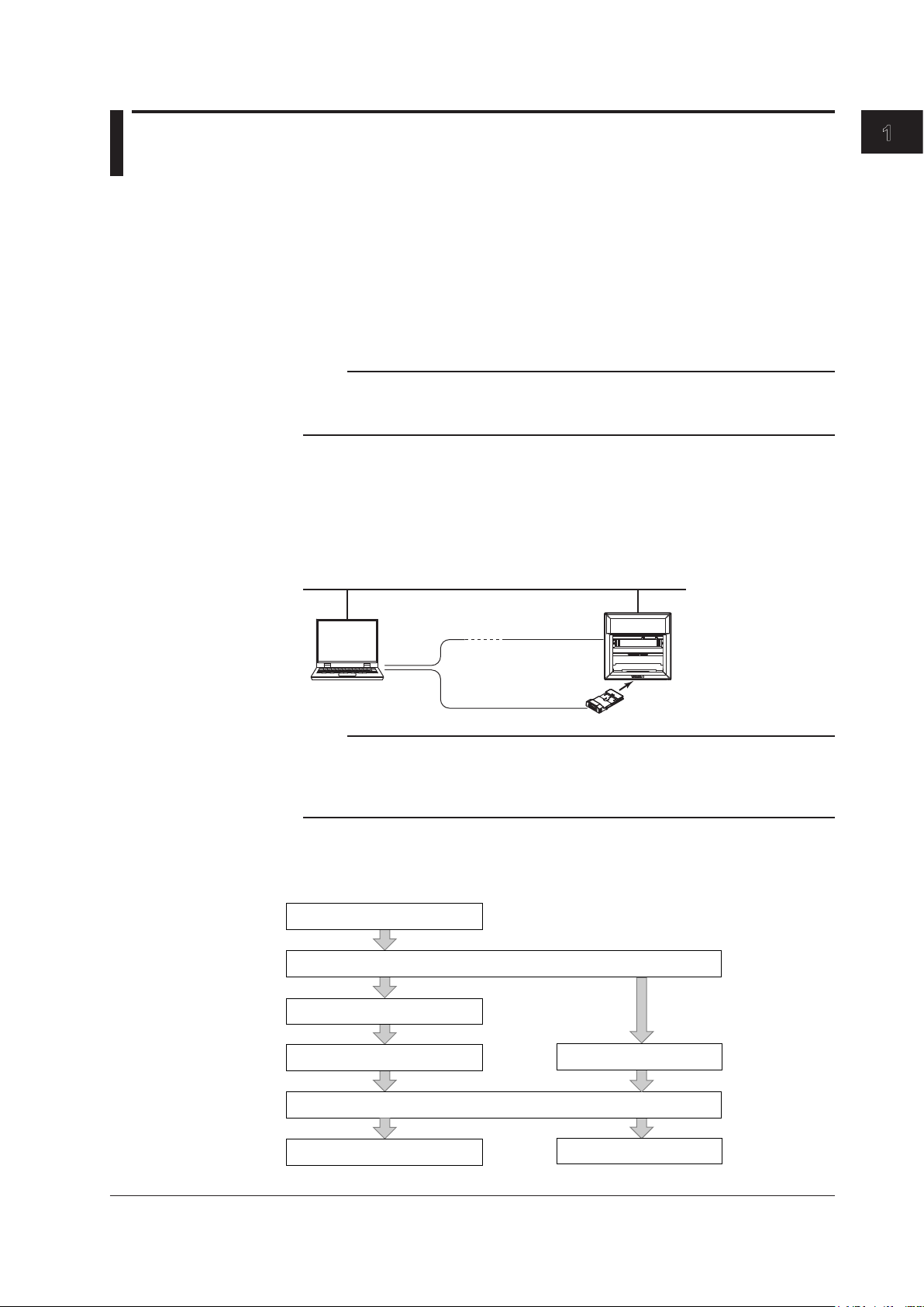
PC
Ethernet
Communication
Interface (/C7)
RS-422/485
Communication
Interface (/C3)
Interface unit
µR10000, µR20000
Connecting the recorder and the PC
Starting the software
Setting the communication mode
Loading setup data of the recorder
Changing the settings
Sending setup data to the recorder
Opening a setup data file
Saving the satup data
To change the settings of the recorder
To change a setup data file
(Section 2.1)
(Section 2.2)
(Section 2.3)
(Sections 2.4 to 2.8)
(Section 2.9)
(Section 1.4)
(Section 2.3)
(Section 2.10)
1.1 Overview of the Configuration Software
Function
This software program is used to configure the µR10000 and µR20000 from a PC.
The setup data can be created using any of the methods below to configure the recorder.
• Load the setup data from the connected recorder and change
• Open a saved setup data and change the settings.
• Create new setup data.
The setup data can be saved to the hard disk on the PC. The setup information can also
be printed.
Note
This program cannot be used to set the following items.
• Date/Time (Setting mode)
• RS-422/485, Ethernet, and pen and dot printing position adjustment (Basic Setting mode)
Connecting to the Recorder
A connection to a PC can be made using the RS-422/485 communication interface
(/C3 option) or the Ethernet communication interface (/C7 option) of the recorder. In
the case of the RXA10-02, the interface unit can be used to connect to the recorder
through the RS-232 communication interface of the PC even if the recorder is not
equipped with a communication interface.
Before Using the Software
the settings.
Flow of Operation
Note
When using the interface unit, turn OFF the device that is connected to the RS-422/485
communication interface (/C3 option) on the recorder rear panel or disconnect the cable. Data
may be sent to the device connected to the RS-422/485 communication interface on the rear
panel when the interface unit is communicating.
The flow of operation of the program is shown below.
IM 04P01B01-61E
1-1
Page 10

1-2
IM 04P01B01-61E
1.2 PC System Requirements
Hardware
• PC
When Using Windows 2000 or Windows XP
CPU: Pentium III 600-MHz or higher (800-MHz Pentium III or higher recommended).
Memory: 512 MB or more.
Hard disk: Free disk space of 10 MB or more.
When Using Windows Vista
CPU:
Memory: 1 GB or more.
Hard disk: Free disk space of 200 MB or more.
When Using Windows 7
32-bit
CPU: Intel Pentium IV, 3.0 GHz or faster x64 or x86 processor
Memory: 2 GB or more.
64-bit edition:
CPU: Intel x64 processor that is equivalent to Intel Pentium IV, 3.0 GHz or faster
Memory: 2 GB or more.
Hard disk: Free disk space of 200 MB or more.
• CD-ROM drive
A CD-ROM drive supported by the OS.
• Mouse
A mouse supported by the OS.
• Monitor
When Using Windows 2000 or Windows XP
A monitor supported by the OS of 1024 × 768 dpi or higher and 32K colors or more (64
When Using Windows Vista or Windows 7
A mo
• Communication port
An RS-232 port or an Ethernet port supported by the OS.
• Printer
A printer supported by the OS. An appropriate printer driver for the OS is also required.
Pentium IV, 3.0 GHz or faster
edition:
Pentium IV, 3.0 GHz or faster
K colors recommended).
nitor supported by the OS of 1024 × 768 dpi or higher and 65,536 colors or more.
Operating System
• Windows 2000 SP4
• Windows XP Home Edition SP3
• Windows XP Professional SP3 (excluding Windows XP Professional x64 Edition)
• Windows Vista Home Premium SP1, SP2 (excluding the 64-bit edition)
• Windows Vista Business SP1, SP2 (excluding the 64-bit edition)
• Windows 7 Home Premium (32-bit and 64-bit editions)
• Windows 7 Professional (32-bit and 64-bit editions)
Note
The PC must have Courier New font installed.
Page 11

1
1.3 Installing the Configuration Software
A serial number is required to install the configuration software. The serial number is
indicated on the CD-ROM case. Please have the serial number ready.
Installing the Software
Start Windows. Log onto Windows as an administrator.
1.
Insert the CD-ROM containing the software into the CD-ROM drive.
2.
The installation program starts automatically.
Click the Run button for the Configuration Installation. Proceed with the
3.
installation according to the instructions that appear on the screen.
If the installation program does not start automatically, carry out the procedures
.
below
Double-click the CD-ROM icon from “My Computer” to open the CD-ROM drive
4.
window.
Double-click the “Setup.exe” file in the root directory. The installation will start after
5.
a short time. Then, follow the instructions on the screen.
Note
• Exit memory resident programs such as virus protection programs before installation.
• Set the OS and program languages to the same language. Normal operation cannot be
guaranteed if you install the software under a different language than the OS.
• When reinstalling the software, uninstall it first.
• To uninstall the program, follow the procedures below.
Double-click “Add/Remove Programs” in the Control Panel and uninstall the program.
1.
As necessary, back up the setup data files with .pul extension in the directory in which
2.
the configuration software was installed to a different directory.
Delete the files (various data files and subdirectories) that were created after the
3.
installation of the program. Also, delete the directory in which the program was installed.
Before Using the Software
IM 04P01B01-61E
1-3
Page 12
1-4
IM 04P01B01-61E
1.4 Connecting the Recorder and the PC
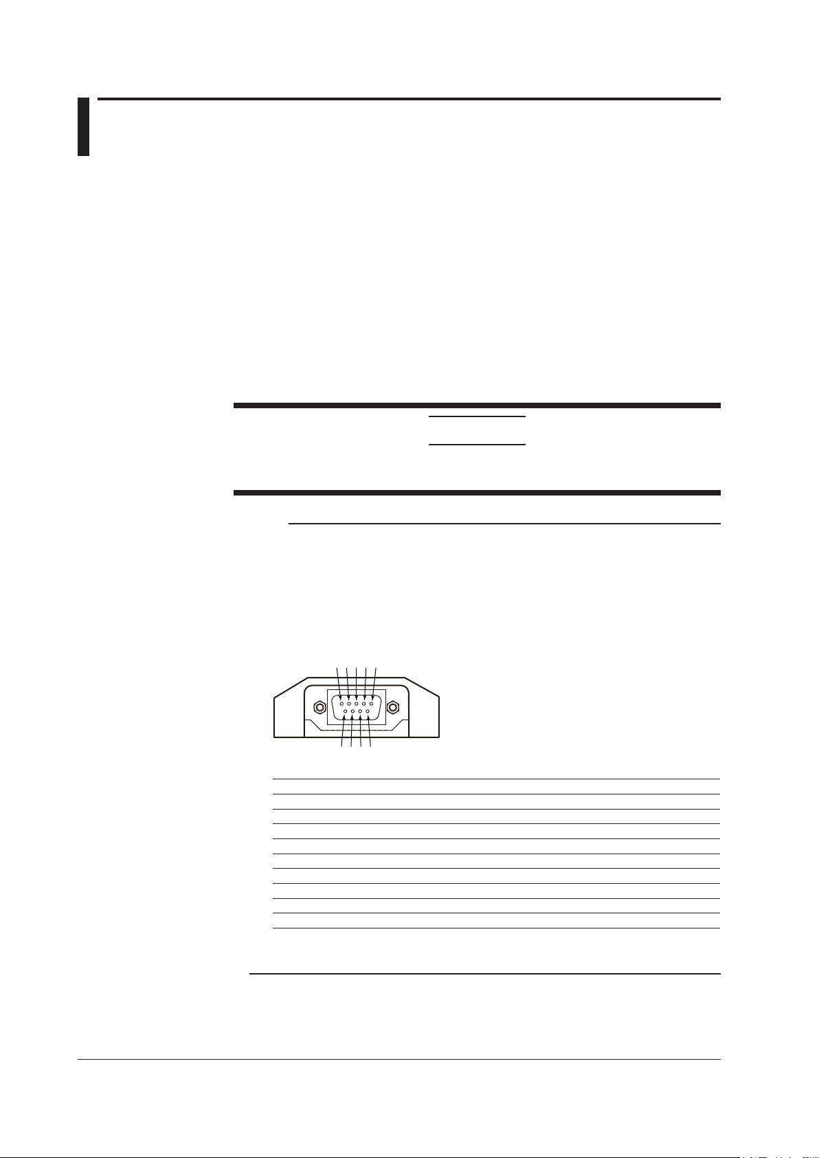
1 2 3 4 5
6 7 8 9
Interface unit (D-Sub 9-pin plug)
Using the Ethernet Communication Interface (/C7 Option)
For the procedure to connect the recorder and the PC, see section 2.2, “Connecting the
Ethernet Interface” in the µR10000/µR20000 Communication Interface User’s Manual (IM
04P01B01-17E).
Using the RS-422/485 Communication Interface (/C3 Option)
For the procedure to connect the recorder and the PC, see section 3.2, “Terminal
Arrangement and Signal Names and the Connection Procedure of the RS-422/485
Communication Interface” in the µR10000/µR20000 Communication Interface User’s
Manual (IM 04P01B01-17E).
Using the Interface Unit (For the RXA10-02)
CAUTION
Do not insert or remove the interface unit while the recorder is turned ON. If you do,
the internal circuit of the recorder and/or the interface unit may be damaged.
Note
• When using the interface unit, turn OFF the device that is connected to the RS-422/485
communication interface (/C3 option) on the recorder rear panel or disconnect the cable.
Data may be sent to the device connected to the RS-422/485 communication interface on
the rear panel when the interface unit is communicating.
• Use a D-Sub 9-pin RS-232 cable (cross cable) to connect the PC and the interface unit (The
connector on the interface unit is a D-Sub 9-pin plug (male)).
Pin Assignments
1 CD Carrier Detect
2 RXD Receive Data
3 TXD Transmit Data
4 DTR Data Terminal Ready
5 GND System Ground
6 SDR Data Set Ready
7 RTS Request to Send
8 CTS Clear to Send
9 RI Ring Indicator
Pins 4 and 6 are shorted internally
Pins 7 and 8 are shorted internally
.
.
Page 13
1
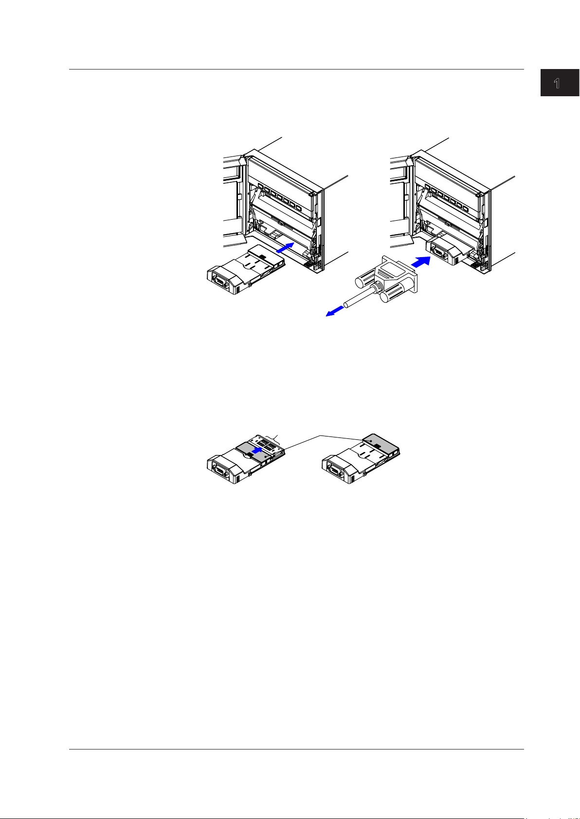
Interface unit
Interface unit
RS-232 Cable
To the PC
Cover
Terminal
section
1.4 Connecting the Recorder and the PC
• Connecting the Recorder and the PC
Turn OFF the recorder and the PC.
1.
Insert the interface unit in the opening under the chart cassette.
2.
Insert it until it clicks in place.
Before Using the Software
• Disconnecting the Recorder from the PC
Connect the interface unit and the PC’s RS-232 connector with an RS-232 cable.
3.
Turn ON the recorder first and then the PC.
4.
Turn OFF the recorder and the PC.
1.
Pull out the interface unit.
2.
Place the cover over the terminal section of the interface unit.
3.
IM 04P01B01-61E
1-5
Page 14
1
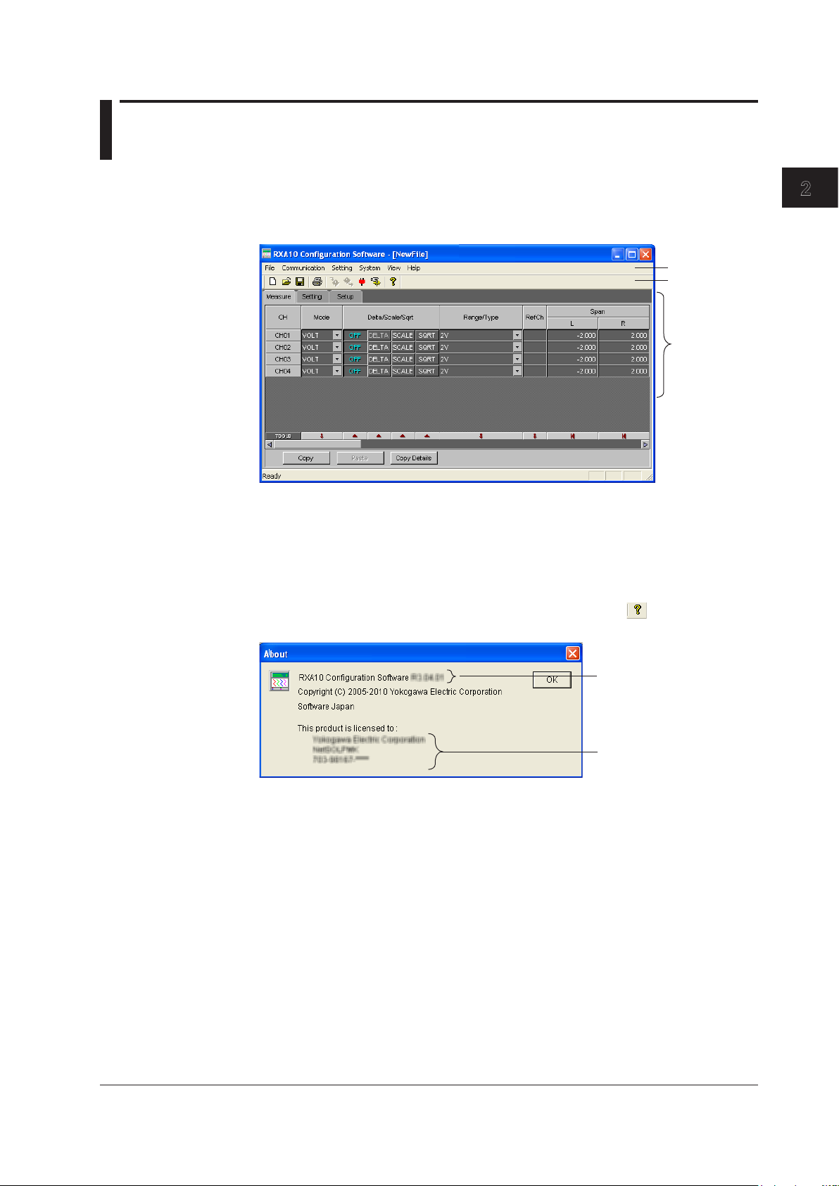
2
Setup data
Toolbar
Menu bar
Displays the serial number.
Displays the version number.
Chapter 2 Configuring the Recorder
2.1 Starting/Closing the Software and Showing
Version Information
Starting the Software
From the task bar, click Start, point to Programs, and choose RXA10 Configuration
Software in RXA10 Configuration Software folder.
The software starts.
Configuring the Recorderr
Closing the Software
From the File menu, choose Exit, or click the X button.
The configuration software window closes.
Showing Version Information
From the Help menu, choose About. You can also click the icon ( ) on the toolbar.
The About dialog box opens.
Click OK to close the dialog box.
IM 04P01B01-61E
2-1
Page 15
2-2
IM 04P01B01-61E
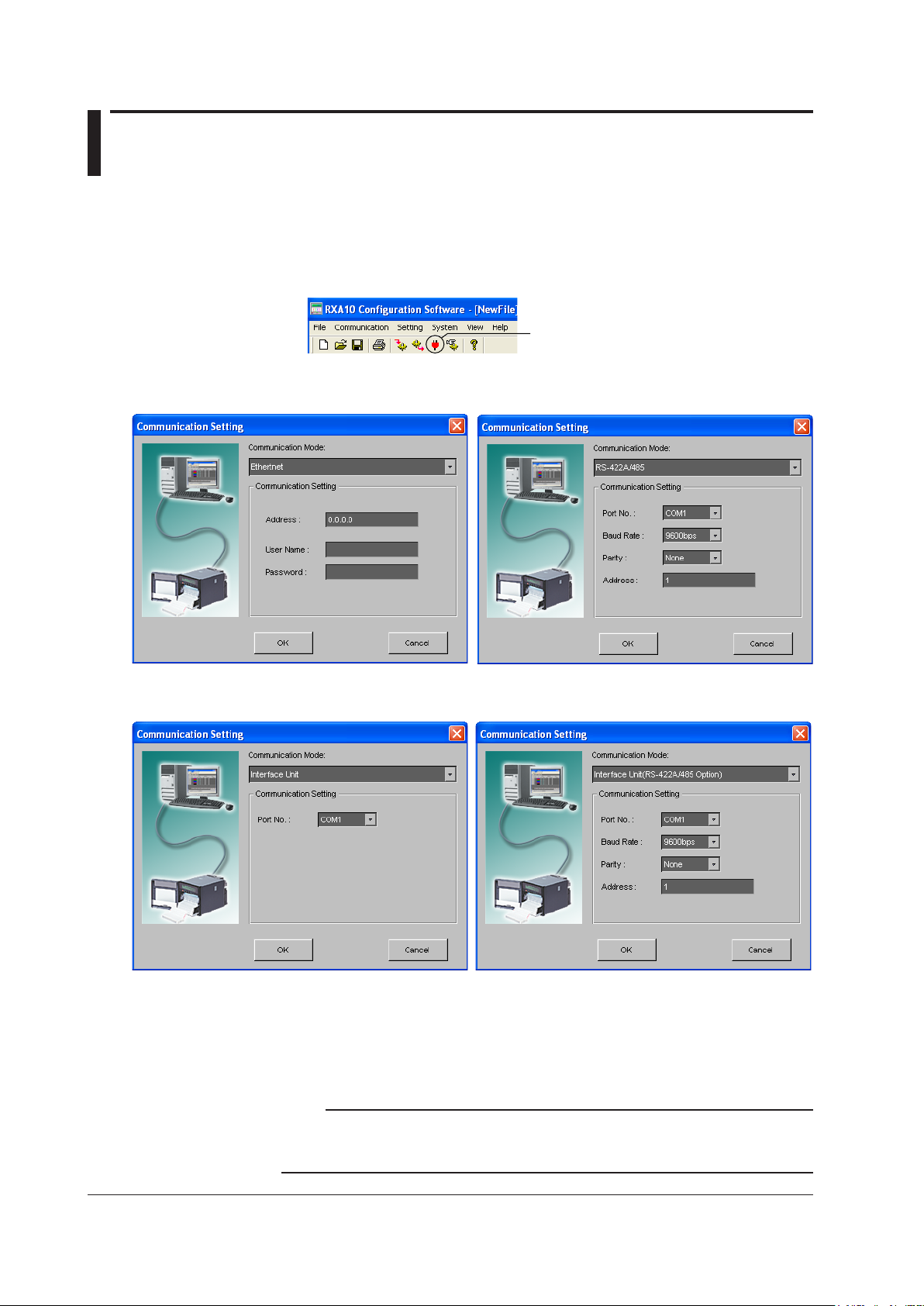
2.2 Setting the Communication Mode for
Communication setting icon
When using Ethernet (/C7 option) When using the RS-422/485 interface (/C3 option)
When using the interface unit
When using the interface unit on a model with the
RS-422/485 interface (/C3 option)
Connecting to the Recorder
Set the communication mode and parameters according to the type of connection
between the PC and the recorder.
From the Communication menu, choose Communication Setting. You can
1.
also click the Communication Setting icon on the toolbar. The Communication
Setting dialog box opens.
Set the communication mode and parameters.
2.
Click OK.
3.
The dialog box closes, and the communication between the PC and the recorder
Click Cancel to cancel the settings and close the dialog box.
is enabled.
Note
After starting the program, be sure to check the communication settings and click OK.
After the communication settings are checked, Receive setting and Send setting of the
Communication menu become selectable.
Page 16

1
2
2.2 Setting the Communication Mode for Connecting to the Recorder
• Ethernet
• Address
Enter the IP address or host name of the recorder.
• User Name and Password
• When using the login function on the recorder
Login as an administrator.
• When not using the login function on the recorder
Login with the user name “Admin.”
Password is not necessary.
• RS-422/485
• Port No.
Select the port from COM1 to COM9.
• Baud Rate and Parity
Set the same values as the recorder.
• Address
Enter the recorder’s address.
• Interface Unit
• Port No.
Select the port from COM1 to COM9.
Configuring the Recorderr
• Interface Unit (RS-422/485 Option)
• Port No.
Select the port from COM1 to COM9.
• Baud Rate and Parity
Set the same values as the recorder.
• Address
Enter the recorder’s address.
IM 04P01B01-61E
2-3
Page 17
2-4
IM 04P01B01-61E
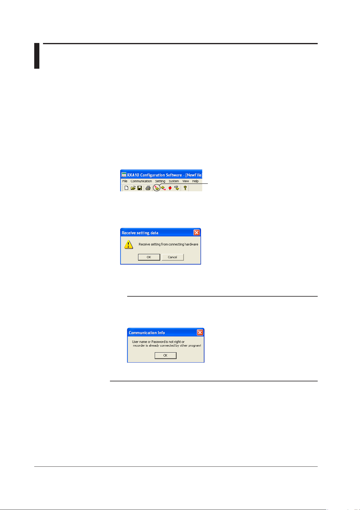
2.3 Loading the Setup Data or Creating New Setup
Receive setting icon
Data
The following three methods are available for creating setup data.
• Load the setup data of the recorder
• Open a setup data le.
• Create new setup data.
Loading the Setup Data of the Recorder
Before carrying out the following procedure, check to see that the communication
mode and parameters are set correctly. For details, see section 2.2, “Setting the
Communication Mode for Connecting to the Recorder.”
From the Communication menu, choose Receive Setting. You can also click
1.
the Receive setting icon on the toolbar. A confirmation dialog box for receiving
settings opens.
Click OK.
2.
The reception starts. When the reception of the settings is complete, a message
appears to indicate it.
Click OK.
3.
The loaded setup data is displayed.
Note
• If the message in the figure below appears, check the following:
• That the communication settings are matched with the settings on the recorder.
• That there are no users accessing the recorder or that the maximum number of users is
• Note that if setup data is received when the recorder is in Basic Setting mode, the setup
data in the middle of the configuration will be received.
not exceeded.
Page 18
1
2
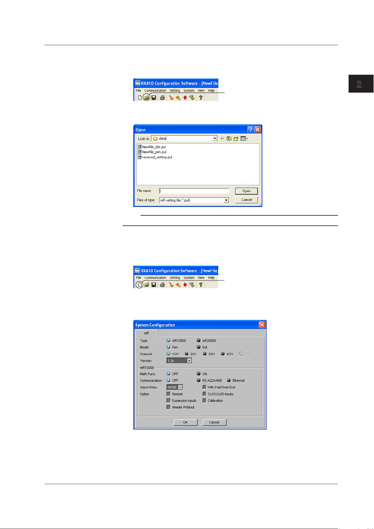
Opening a Setup Data File
Open icon
New icon
From the File menu, choose Open. You can also click the Open icon. The Open
1.
dialog box opens.
2.3 Loading the Setup Data or Creating New Setup Data
Select the desired file, and click Open.
2.
The setup data is displayed.
Note
The extension to setup data files is .pul.
Creating New Setup Data
From the File menu, choose New. You can also click the New icon. The System
1.
Configuration dialog box opens.
Configuring the Recorderr
• Type, Model, Channel, and Style
Type: Recorder types.
Model: Pen model or dot model.
Channel: The number of measurement channels on the recorder.
Style: The style number of the recorder.
Set the system configuration of the recorder, and click OK.
2.
A setup window with the specified system configuration opens with the settings
set to default values.
IM 04P01B01-61E
2-5
Page 19

2-6
IM 04P01B01-61E
2.3 Loading the Setup Data or Creating New Setup Data
• Options
Math Func.: Computation function (/M1 option)
Communication RS-422/485: RS-422/485 Communication Interface (/C3)
Communication Ethernet: Ethernet Communication Interface (/C7)
Alarm Relay 2p: Alarm output relay 2 points (/A1)
Alarm Relay 4p: Alarm output relay 4 points (/A2)
Alarm Relay 6p: Alarm output relay 6 points (/A3)
Alarm Relay 12p: Alarm output relay 6 points (/A4, µR20000)
Alarm Relay 24p: Alarm output relay 6 points (/A5, µR20000)
With FAIL/Chart End: FAIL/Chart End Detection and Output (/F1)
Remote: Remote Control Input (/R1)
Cu10, Cu25 Inputs: Cu10, Cu25 RTD Input (/N1)
Expansion Inputs: Expansion Inputs (/N3)
Calibration:* Calibration Correction (/CC1)
Header Printout:** Header Printout (/BT1)
* Function available on recorders with firmware version 1.21 or later.
** Function available on recorders with firmware version 1.31 or later.
Checking/Changing the System Configuration of the Setup Data
• Checking the System Configuration
With the setup data displayed in the window, choose System Conguration from the
System menu.
The System Conguration dialog box opens.
Check the system conguration that is shown, and click OK.
The dialog box closes.
• Changing the System Configuration
With the setup data displayed in the window, choose System Conguration from the
System menu.
The System Conguration dialog box opens.
Change the system conguration, and click OK.
The conrmation dialog box opens. Click OK to open a setup window with the
specied system conguration with the settings set to default values.
Initializing the Settings
1.
The Initialize dialog box opens.
2.
Note
For the default settings, see section 4.3, “Menu Structure, Settings, and List of Default
From the Setting menu, choose Initialize.
Click OK to initialize the settings.
Values” in the µR10000 Recorder User’s Manual (IM 04P01B01-01E) or µR20000 Recorder
User’s Manual (IM 04P02B01-01E).
Page 20
1
2
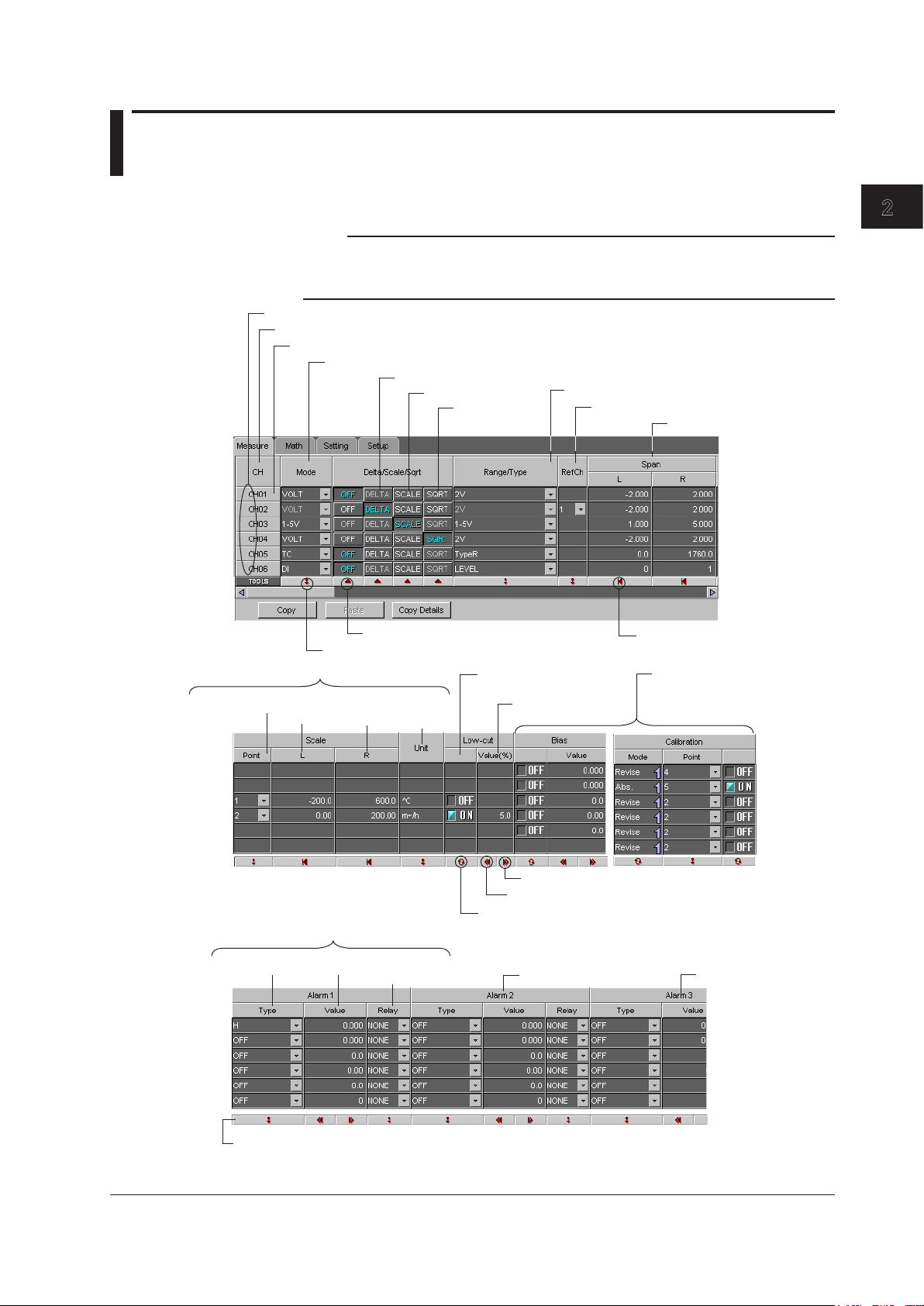
2.4 Setting the Measurement Channels
Click twice to unselect the channel.
Double-click to open a setup dialog box for the respective channel.
Delta input
Linear scaling
Square root
computation
Recording span
Input type
Input range
Alarm 2
Reference channel for delta input
Scale value of linear scaling
Rightmost
value
Leftmost
value
Decimal point
position
Turns the low-cut
function ON/OFF
Either “Bias” or “Calibration”
(/CC1 option) is displayed
depending on the settings in
Basic Setting mode (see page
2-25).
Low-cut value
Alarm 3
Sets the default value.
Sets the settings of the first channel to the other channels.
Set collectively.
Drag the pointer while holding down the left mouse button to select multiple channels.
Sets the minimum possible value.
Sets the maximum possible value.
Toggles ON/OFF collectively for each click.
The tool buttons apply to the selected range of channels when channels are selected.
They apply to all channels when a channel is not selected.
Unit
Alarm 1
Output relay
number
Alarm valueAlarm type
Click the Measure tab. You can also choose Measure Channels from the Setting menu.
Note
The following items may be shown or hidden depending on the settings in the Basic Setting
mode.
Low-cut, Bias, Calibration Correction (/CC1 option), Alarm Delay, and Partial.
Configuring the Recorderr
IM 04P01B01-61E
2-7
Page 21

2-8
IM 04P01B01-61E
Partial expanded recording
Bar graph display mode
Channel recording color (dot model)
Turns trend recording ON/OFF (dot model)
Turns ON/OFF periodic printout
Types of measured values
to be printed periodically
Sampling count of moving average (dot model)
or filter time constant (pen model)
Alarm 4
Tag
Alarm delay time
Recording zone
Click twice to unselect the correction points.
Correction value
Value at the correction point
Set the settings of the first point in the selected range
to the other points.
Given channels are copied and pasted to other channels.
Channel range to be copied.
Drag the pointer while holding down the left mouse button to select multiple correction points.
Channel range to be pasted.
Click OK to copy and paste.
2.4 Setting the Measurement Channels
Correction Points for Calibration Correction (/CC1 Option)*
* For recorders with firmware version 1.21 or later
Set the correction points for each channel to use the calibration correction. You can set
these points after setting the Calibration on the Measure tab.
Click the Calibration tab. You can also choose Calibration from the Setting menu.
Page 22

1
2
Input (Mode, Range/Type, and Span)
Set the input type (Mode, Range/Type) and the recording span (Span).
Mode Relevant Settings
VOLT (voltage) Range/Type, Span L, and Span R
TC (thermocouple) Range/Type, Span L, and Span R
RTD (resistance temperature detector) Range/Type, Span L, and Span R
1-5V (1-5V) Range/Type, Span L, and Span R
DI (voltage level/contact input) Range/Type, vpan L, and Span R
SKIP (Measurement OFF) None
Note
• Click the Default button ( ) for Span L to set the minimum value within the measurable
range. Click the Default button for Span R to set the maximum value within the measurable
range.
• The span L and R values that have been changed are displayed in orange, but the values
are valid. When data adjustment (see section 2.8) is executed, the values change back to
white.
• When a value outside the measurable range is entered or when the span L and span R
values are set to the same value, they are corrected when the data is checked.
• If SKIP is selected, other settings are discarded.
Delta Computation (Delta and RefCh)
Measures the difference between the input value of its own channel and that of the reference
channel. Delta computation can be specified when the Mode setting is VOLT, TC, or RTD.
Delta/Scale/Sqrt
Select DELTA.
2.4 Setting the Measurement Channels
Configuring the Recorderr
RefCh
Select the reference channel.
Specify a channel that is smaller in channel number than itself for the reference channel.
Square Root Computation
The square root of the input value is calculated, the result is scaled to a value in the
appropriate unit, and used as the measured value of the channel. Also, the low-cut function
can be used. This setting can be used only when the input mode is set to VOLT.
Delta/Scale/Sqrt
Select SQRT.
Low-cut
This appears when low-cut is enabled (see page 2-25) in Basic Setting mode.
For Square Root Computation
ON: Sets measured values below the specified value to 0 (the leftmost value of
the scale).
Value (%):
The measured value to be low-cut. Set the value in the range of 0.0% to 5.0%
of the recording span.
For 1-5V Input
ON: Sets measured values below 0% input to 0 (the leftmost value of the scale).
Linear Scaling
Scale (Point, L, and R)
The input values are scaled to values in the appropriate unit to be used as measured
values. Set the leftmost value of the scale (L) and the rightmost value of the scale (R)
using a mantissa and decimal point position.
Mantissa:
Decimal position:
IM 04P01B01-61E
–20000 to 30000
0 (the number of digits right of the decimal is 0) to 4 (the number of
digits to the right of the decimal is 4)
2-9
Page 23

2-10
IM 04P01B01-61E
9.8°C
90.5°C
10.0°C
90.0°C
0.2°C
–0.5°C
10.0°C
90.0°C
Datum
(Correction point)
Value after Correction Value (Correction value)
when Mode is Revise when Mode is Abs.
2.4 Setting the Measurement Channels
Note
The L and R values that have been changed are displayed in orange, but the values are valid.
When data adjustment (see section 2.8) is executed, the values change back to white.
Unit
Enter the unit using up to six characters. The characters that can be used are as follows
(see section 2.12):
Alphabet, numbers, symbols (%, #, °, @, +, –, *, /, (, ), µ, Ω,
Bias
This appears when bias is enabled (see page 2-25) in Basic Setting mode.
ON/OFF and Value
Select ON to use bias.
The range of bias that can be specified is ±10% of the measurable range of the input
range. For example, the range is –0.4 V to 0.4 V for the 2 V input range. For channels on
which scaling is set, the range is ±10% of the scaling range span. A bias cannot be set
on channels set to ON/OFF input (DI).
2, 3
, .), and space
Calibration
(/CC1 Option)*
* For recorders with firmware version 1.21 or later
Settings on the Measure Tab
Setting items are displayed when the calibration correction is enabled in Basic Setting
mode (see page 2-25).
• Mode
Select Revise or Abs. to specify correction values. See the table below.
• Point
Input number of correction points (up to 16 points) including rst and last points.
• ON/OFF
Select ON to use the calibration correction.
Settings on the Calibration Tab
• Datums
Set a value of the correction point (input value). Follow the conditions below.
Datum of rst correction point < Datum of second correction point ≤ Datum of third
correction point ≤ Datum of fourth correction point ≤ ......
• Value
Set a correction value corresponding to the datum. Follow the conditions below.
• When Mode is set to Revise
“Datum + Value” of rst correction point < “Datum + Value” of second correction
point < “Datum + Value” of third correction point < ......
• When Mode is set to Abs.
Value of of rst correction point < Value of of second correction point < Value of
third correction point < ......
The table below shows some examples.
Note
If the difference between values of the correction points, or the difference between values after
correction, are small, for example several digits, an error may occur when you send the setup
data to the recorder. In that case, change the set values.
Page 24

1
2
Alarm 1 to 4
2.4 Setting the Measurement Channels
Four alarms (Alarm 1 to 4) can be specied on each channel.
Type
Type Values Description
H An alarm occurs when the measured value exceeds the specified value.
L An alarm occurs when the measured value falls below the specified value.
h(dH)* An alarm occurs when the difference in the input values of two channels is
greater than or equal to the specified value.
l(dL)* An alarm occurs when the difference in the input values of two channels is
less than or equal to the specified value.
R(RH) The rate-of-change of the measured values is checked over a certain time
(interval). An alarm occurs if the rate-of-change of the measured value in the
rising direction is greater than or equal to the specified value.
r(RL) The rate-of-change of the measured values is checked over a certain time
(interval). An alarm occurs if the rate-of-change of the measured value in the
falling direction is greater than or equal to the specified value.
T** An alarm occurs when the measured value remains above the alarm value for
the specified time period.
t** An alarm occurs when the measured value remains below the alarm value for
a specified time period.
*
Can be specified on channels set to delta computation.
T and t can be selected when the alarm delay function is enabled in Basic Setting mode.
**
Alarm Value
Alarm is generated using the specified value as the boundary. The selectable range of
alarm values vary depending on the input mode and range.
Configuring the Recorderr
Relay
To output relays, select the output relay number. Otherwise, select NONE.
Alarm Delay
An alarm occurs when the measured value remains above or below the alarm value for a
specified time period (alarm delay time).
Filter and Moving Average
Filter (Pen Model)
To use the input filter, select the time constant (2 s, 5 s, or 10 s).
Moving Average (Dot Model)
To use the moving average, select the sampling count (2 to 16).
Tag
Enter the tag using up to 7 characters. The characters that can be used are as follows (see
section 2.12):
Alphabet, numbers, symbols (%, #, °, @, +, –, *, /, (, ), µ, Ω,
Note
The setting of whether to use channel numbers or tags for printing is specified in Print Setting
under the Setup tab.
Zone
Sets the zone in which the measured values of each channel are recorded. Set the
position (mm) on the chart paper for the leftmost value of the recording zone (L) and
rightmost value of recording zone (R).
•
Selectable range: 0 to 100 mm (µR10000), 0 to 180 mm (µR2
Set R to a value greater than L, and make the zone width (R – L) greater than or equal
to 5 mm.
2, 3
, .), and space
0000)
IM 04P01B01-61E
2-11
Page 25

2-12
IM 04P01B01-61E
2.4 Setting the Measurement Channels
Bar Graph
Selects the display mode of the bar graph.
Normal: Sets the base point of the graph to the smaller of the values Span L or Span R (or
Scale L or Scale R).
Center: Sets the base point of the bar graph to the 50% position of the span.
Partial
This appears when partial expanded recording is enabled in Basic Setting mode.
Expand (%)
Set the boundary position for the partial expanded recording. The range is from 1 to 99%.
Boundary
Set the boundary value to a value within the span (within the scale when linear scaling is
used).
Color (Dot Model)
Click the appropriate box in the Color column to open the Recording Color dialog box.
Select the recording color of the respective channel.
Print Out
Trend (Dot Model)
Turns trend recording ON/OFF.
Periodic Printout
Periodic
Turns periodic printout ON/OFF.
Selects the type of measured values to be printed in periodic printout. This setting is
activated when Mode for Periodic Print in Print Setting (see page 2-24) in Basic Setting
mode is set to Report.
Mode
AVE: Average value over the interval.
MIX: Minimum, maximum, and average values over the interval.
SUM: Sum value over the interval.
MIN: Minimum value over the interval.
MAX: Maximum value over the interval.
INST: Instantaneous value
SUM Scale
When the mode is SUM, set the sum scale.
SUM sums the data every computation interval. For flow values that have units /s, /min, /h,
or /day, a simple summation results in the actual value not matching the computed result,
because the scan interval and the unit of the input values are different. In such cases, set
the sum scale to match the unit of the input value. In effect, the sum value with the same
unit as that of the input value is calculated.
For example, if the scan interval is 1 s, and the input value is 100 m
summation would add 100 every 1 s resulting in 6000 after one minute. However, if the
sum scale is set to /min, then 1 s/60 s is multiplied every scan interval before the value is
added giving a result with an m
OFF: Simply sums the measured values.
/s: Sums by converting the measured values to a value over 1 second.
/min: Sums by converting the measured values to a value over 1 minute.
/h: Sums by converting the measured values to a value over 1 hour.
/day: Sums by converting the measured values to a value over 1 day.
3
/min unit.
3
/min, a simple
Page 26

1
2
Copying and Pasting the Settings
Channel number
Set each item, and click here.
Applies the settings.
Applies the settings specified on the [Measure] tab.
The settings specified for a given channel can be copied and pasted to other channels.
Click the copy source channel number. To select multiple channels, drag the
1.
pointer while holding down the left mouse button.
Click Copy ( ).
2.
Click the copy destination channel number. To select multiple channels, drag the
3.
pointer while holding down the left mouse button.
Click Paste ( ).
4.
The items that are to be copied/pasted can be limited
Click Copy Details to open the Channel Copy Details dialog box.
Select the check boxes for the items you wish to copy/paste, and click OK.
2.4 Setting the Measurement Channels
Configuring the Recorderr
Setting Each Channel
Double-click a channel number. The dialog box for that channel opens.
IM 04P01B01-61E
The settings in this dialog box are the same as those on the Measure tab.
2-13
Page 27

2-14
IM 04P01B01-61E
2.5 Setting the Computation Channels (/M1 Option)
Tag
Alarm delay time
Channel recording color (dot model)
Turning ON/OFF computation
Equation
Constants used
in equations
Click twice to unselect the channel.
Double-click to open a setup dialog box for the respective channel.
Drag the pointer while holding down the left mouse button to select multiple channels.
Recording span
Rightmost
value
Unit
Leftmost
value
Decimal point
position
Alarm 1
Output relay
number
Alarm valueAlarm type
Sets the settings of the first channel in the selected
range to the other channels.
Partial expanded recording
Bar graph display mode
Turns ON/OFF periodic printout
Types of measured values
to be printed periodically
Turn trend recording ON/OFF (dot model)
Recording zone
Alarm 4
Sets the default value.
Toggles ON/OFF collectively for each click.
Sets the minimum possible value.
Sets the maximum possible value.
The tool buttons apply to the selected range of channels when channels are selected.
They apply to all channels when a channel is not selected.
Click the Math tab. You can also choose Math Channels from the Setting menu.
Page 28

1
2
Turning ON/OFF Computation
Turns ON/OFF computation.
Expression
Enter the expression using up to 120 characters. For details on the expression, see
section 9.2, “Setting the Computing Equation” in the µR10000 Recorder User’s Manual (IM
04P01B01-01E) or µR20000 Recorder User’s Manual (IM 04P02B01-01E).
Constant
Sets the constants to be used in computing equations. Up to 30 constants can be
specied.
Range of values (maximum significant digits is 5):
–9.9999E+29 to –1.0000E–30, 0, 1.0000E–30 to 9.9999E+29
Span
Set the recording span.
Span (Point, L, and R)
Set the leftmost value of the span (L) and the rightmost value of the span (R) using a
mantissa and decimal point position.
Mantissa: –9999999 to 99999999
Decimal position:
2.5 Setting the Computation Channels (/M1 Option)
Configuring the Recorderr
0 (the number of digits right of the decimal is 0) to 4 (the number of
digits to the right of the decimal is 4)
Unit
Enter the unit using up to six characters. The characters that can be used are as follows
(see section 2.12):
Alphabet, numbers, symbols (%, #, °, @, +, –, *, /, (, ), µ, Ω,
Alarm 1 to 4
For the procedure, see section 2.4, “Setting the Measurement Channels.”
The alarm types that can be specified on a computation channel is high limit (H), low limit
(L), delay high limit (T), and delay low limit (t).
TLOG Computation (TLOG)
Sets TLOG computation and the printing of the computed values.
Timer
Sets the timer used in TLOG computation and printout to Periodic (periodic printout
timer), 1 (timer 1), or 2 (timer 2). For a description of the timer setting, see page 2-24.
SUM Scale
Sets the sum scale when determining the sum value in TLOG computation. For a
description of sum scale, see page 2-12.
Tag, Zone, Bar Graph, Partial, Color (Dot Model), and Trend
For the procedure, see section 2.4, “Setting the Measurement Channels.”
2, 3
, .), and space
Copying and Pasting the Settings
The settings specified for a given channel can be copied and pasted to other channels.
For the procedure, see “Copying and Pasting the Settings” on page 2-13.
IM 04P01B01-61E
2-15
Page 29

2-16
IM 04P01B01-61E
Buttons to select
the operator type
Operator buttons
<Select Operator dialog box>
2.5 Setting the Computation Channels (/M1 Option)
Setting Each Computation Channel
Double-click a channel number. The dialog box for that channel opens.
Setting the Equation
Click the Ope. button to open the Select Operator dialog box.
Select the operator type to switch the displayed operator buttons. Click a operator button
to enter the operator in Exp.
The items in the math channel tab can be configured for each channel. The settings in
this dialog box are the same as those on the Math tab.
Page 30

1
2
2.6 Setting the Items in Setting Mode and the Data
Click here (or choose [Setting] > [SET [Regular] Setting] > [Chart Speed]/[Trend Interval])
Chart speed
Secondary chart speed
Trend interval (dot model)
Display Method
Click the Setting tab. You can also select the item by choosing SET [Regular] Setting
from the Setting menu.
Chart Speed/Trend Interval
Chart Speed
• Pen Model
The chart speed can be selected from 82 settings shown below.
Chart speed on the pen model (unit: mm/h)
5 6 8 9 10 12 15 16 18 20
24 25 30 32 36 40 45 48 50 54
60 64 72 75 80 90 96 100 120 125
135 150 160 180 200 225 240 250 270 300
320 360 375 400 450 480 500 540 600 675
720 750 800 900 960 1000 1080 1200 1350 1440
1500 1600 1800 2000 2160 2250 2400 2700 2880 3000
3600 4000 4320 4500 4800 5400 6000 7200 8000 9000
10800 12000
• Dot Model
The chart speed can be set in the range of 1 to 1500 mm/h in 1 mm steps.
Configuring the Recorderr
Trend Interval (Dot Model)
Auto: The trend recording interval is set according to the chart speed in the range of
10 s to 90 s so that the dots do not overlap.
Fix: The trend recording interval is fixed to 10 s/6 dots. On models with the
computation function (/M1 option), the dot printing interval varies depending on
the number of measurement and computation channels to be trend recorded.
IM 04P01B01-61E
2-17
Page 31

2-18
IM 04P01B01-61E
Click here (or choose Setting > SET [Regular] Setting > Message)
Message
Format text box
Click the button to enter the displayed
character string in the text box.
Click a text box from 1 to 5. A dialog box used to set
the message format opens.
Copies/Pastes messages.
Click twice to unselect the message.
Drag the pointer while holding down the left mouse button to select multiple
messages.
2.6 Setting the Items in Setting Mode and the Data Display Method
Message
Messages
Set a message using up to 16 characters.
The characters that can be used are as follows (see section 2.12):
Alphabet, numbers, symbols (%, #, °, @, +, –, *, /, (, ), µ, Ω,
2, 3
, .), and space
Page 32

1
2
H:M 5 H:M:S 8
M/D H:M 11 M/D H:M:S 14
D/M H:M 11 D/M H:M:S 14
D.M H:M 11 D.M H:M:S 14
M.D H:M 12 M.D H:M:S 15
Y/M/D H:M:S 19 M/D/Y H:M:S 19
D/M/Y H:M:S 19 D.M.Y H:M:S 19
M.D.Y H:M:S 20
H, M, and S are hour, minute, and second, respectively, for H:M and H:M:S.
M, D, and Y are month, day, and year, respectively for M/D, D/M, D.M , M.D,
Y/M/D, M/D/Y, D/M/Y, D.M.Y, and M.D.Y.
Format symbols and number of characters used
Num. of
Chars
Symbol Num. of
Chars
Symbol Num. of
Chars
Symbol
01 to 24 7
L01 to L16 1 to 16
0A to 1P 9
10th and 11th characters of the message
string (9 characters already used, so this
represents the next characters.)
Message 1 string of the standard function:
Process-1°C
Message 1 printout result: 06/30 10:10 Process-1 134.8°C
Message format 1: M/D H:M L09 01L02
Message value on CH1 (no unit)
Space (number of characters: 1)
Space
1-9th characters of the message string
Date/Time
2.6 Setting the Items in Setting Mode and the Data Display Method
Message Format (/BT1 Option)*
* Function available on recorders with firmware version 1.31 or later.
Set the message format.
Click a text box from 1 to 5. A dialog box used to set the message format opens. Set the
format using the selectable items displayed in the dialog box and space.
Number of characters per message: Up to 35 (µR10000) and up to 69 (µR20000).
Setup Example
Configuring the Recorderr
IM 04P01B01-61E
2-19
Page 33

2-20
IM 04P01B01-61E
Click here (or choose [Setting] > [SET [Regular] Setting] > [Data Display Setup])
Screen tab
When display type is [Flag]
When display type is [Multiple display]
Displayed channel switching interval
Display type
Display of the top section Display of the bottom section
Display type
Displayed channel switching interval
Display channel
Selects the channels on which flag is to be displayed.
2.6 Setting the Items in Setting Mode and the Data Display Method
Data Display Setup
Pict1 Tab to Pict15 Tab
Corresponds to Screen 01 to Screen 15.
• Type
The following display types available. For details on the display types, see section
12.4, “Display Function Specications” in the µR10000 Recorder User’s Manual (IM
04P01B01-01E) or µR20000 Recorder User’s Manual (IM 04P02B01-01E).
Display Type Display Type
Skip (the screen is not displayed) Time/Chart speed
1 CH digital DI/DO
2 CH digital Multiple display (Display in which different screens
4 CH digital
6 CH digital (6-dot models) Tag_1 CH digital
12 CH digital (12/18/24-dot models, µR20000) Tag_2 CH digital
1 CH digital + 1 CH bargraph Tag_1 CH digital + 1 CH bargraph
1 CH digital + 4 CH bargraph (pen models) Tag_1 CH digital + 4 CH bargraph (pen models)
2 CH digital + 2 CH bargraph Status
4 CH bargraph (pen models) System
6 CH bargraph (dot models, µR10000) Batch Name*
Flag Lights out (display with no contents)
Channel alarm status
* Selectable on recorders with firmware version 1.31 or later and header printout (/BT1 option).
can be assigned to the top and bottom sections)
Page 34

1
2
• Interval
Click here (or choose [Setting] > [SET [Regular] Setting] > [Brightness]/[DST])
VFD brightness
Brightness of the internal illumination
For recorders with firmware version 1.02 or earlier
For recorders with firmware version 1.11 or later
Sets the displayed channel switching interval. This item appears when the display
Auto 1s to Auto 5s:
Manual: Switch the channel manually.
• Display (For Flag)
Selects the channels on which ag is to be displayed.
• Channel No. (L)/Channel No. (R) (For Multiple display)
Species the channels to be displayed simultaneously.
Brightness and DST
2.6 Setting the Items in Setting Mode and the Data Display Method
type requires this setting.
Switches the channel at the specied time interval.
Configuring the Recorderr
VFD Display
The brightness can be set to an integer between 1 and 8. The darkest setting is 1; the
brightest setting is 8.
Light
The brightness of the internal light can be set to an integer between 1 and 4. The darkest
setting is 1; the brightest setting is 4. Select OFF to turn off the internal light.
DST
Sets the date/time for switching between standard time and DST.
• For recorders with firmware version 1.02 or earlier
Summer: Date/Time when switching from standard time to DST
Winter: Date/Time when switching from DST to standard time
• For recorders with firmware version 1.11 or later
Start Time: Date/Time when switching from standard time to DST. Specify the day
as n th day of the week of the month.
End T
ime: Date/Time when switching from DST to standard time. Specify the day
as n th day of the week of the month.
IM 04P01B01-61E
2-21
Page 35

2-22
IM 04P01B01-61E
Click here (or choose [Setting] > [SET [Regular] Setting] > [Batch])
Click the text box and enter the text.
Click twice to unselect the line.
Drag the pointer while holding down the left mouse button to select multiple lines.
Copies/Pastes the text.
Displayed only for
End and End2.
2.6 Setting the Items in Setting Mode and the Data Display Method
Batch (/BT1 Option)*
* Function available on recorders with firmware version 1.31 or later.
This appears when batch function is enabled (see page 2-33) in Basic Setting mode.
Set the contents of the start printout and end printout.
The Start2 and End2 tabs are valid when Dual Comment is enabled in Basic Setting
mode.
Batch No.
Enter the batch number using up to 26 characters.
The characters that can be used are as follows (see section 2.12):
Alphabet, numbers, symbols (%, #, °, @, +, –, *, /, (, ), µ, Ω,
Lot No.
This appears when Digit of lot number is specified (see page 2-33) in Basic Setting
mode.
Set the number in the range of 0000 to 9999 or 000000 to 999999. Digit of lot number is
set in Basic Setting mode.
Batch Comment
Set the batch comment using up to 32 characters by 5 lines (µR10000) or 64 characters
by 5 lines (µR20000).
The characters that can be used are as follows (see section 2.12):
Alphabet, numbers, symbols (%, #, °, @, +, –, *, /, (, ), µ, Ω,
Batch Printout
• Batch Name
On: Prints the batch name.
• Chart Speed
On: Prints the chart speed.
• Date/Time
On: Prints the date and time.
2, 3
, and .), and space
2, 3
, and .), and space
Page 36

1
2
2.6 Setting the Items in Setting Mode and the Data Display Method
Batch Action
• Feed Amount
Set the length of chart paper to be fed out before start printout or after end printout in
1-mm steps up to 50 mm.
• Lot No. Auto Increment
On: Increments the lot number when the header printout is completed.
• Ejection of POC
On: Records the portion of the data that remains after recording stops when the pen
offset compensation function is enabled on the pen model.
• Chart feed speed at POC
Species the chart feed speed when recording the portion of the data that remains.
Configuring the Recorderr
IM 04P01B01-61E
2-23
Page 37

2-24
IM 04P01B01-61E
2.7 Setting the Items in Basic Setting Mode
Click here (or choose [Setting] > [SETUP [Basic] Setting] > [Alarm]/[Remote Action])
Click twice to unselect the channel.
Drag the pointer while holding down the left mouse button to select
multiple lines.
Copy/Paste the action.
Click the Setup tab. You can also select the item by choosing SETUP [Basic] Setting
from the Setting menu.
Alarm/Relay/Remote
Diagnosis
ON: Alarm output relay I01 is used for diagnosis output.
Reflash
ON: Alarm output relays I01, I02, and I03 are set to reflash alarm operation.
Relay AND
Set the range of relays (from alarm output relay I01) to take the AND operation. If NONE
is selected, no relays are set to AND operation. All relays are set to OR operation.
Relay Action
Sets whether the output relay is energized or de-energized when an alarm occurs.
Alarm Relay Behavior
Nonhold: Releases the relay output at the same time the alarm is released.
Hold: Holds the relay output until the alarm ACK operation is executed.
Alarm Indicator
Nonhold: Releases the alarm indication at the same time the alarm is released.
Hold: Holds the alarm indication until the alarm ACK operation is executed.
Rate of Change Increase and Rate of Change Decrease
Set the interval of the high limit and low limit on rate-of-change alarm to an integer
between 1 and 15. The interval is set to scan interval × (1 to 15).
The scan interval on the pen model is 125 ms. The scan interval on the dot model is 1 s
or 2.5 s.
Page 38

1
2
2.7 Setting the Items in Basic Setting Mode
Measure Alarm Hysteresis
Sets the alarm hysteresis of measurement channels in the range of 0.0% (OFF) to 1.0%
of the recording span in 0.1 steps. The hysteresis applies to all high limit and low limit
alarms of measurement channels.
Math Alarm Hysteresis (Models with the Computation Function (/M1
Option))
Sets the alarm hysteresis of computation channels in the range of 0.0% (OFF) to 1.0%
of the recording span in 0.1 steps. The hysteresis applies to all high limit and low limit
alarms of computation channels.
Remote (Models with Remote Control Input (/R1 Option))
Remote 1 to Remote 5 corresponds to remote control input terminals 1 to 5. The
following functions can be assigned.
Display Description
NONE No function is assigned.
Record On/Off Starts/stops recording.
Chart speed Changes the chart speed.
Time adjust Adjusts the internal clock to the nearest hour.
MATH start/stop Starts/stops the computation on the computation function
(/M1 option).
MATH reset Resets the computed result of the computation function
(/M1 option).
Manual print Executes manual printout.
Alarm ACK Executes alarm output release.
message # Prints message # (where # is a value between 1 and 5).
Priority to Remote Recording* Starts/stops recording.
Switching Batch Comment* Switches between start printout and start printout 2. Or,
switches between end printout and end printout 2.
*
Selectable on recorders with firmware version 1.31 or later and heade
r printout (/BT1 option).
Configuring the Recorderr
IM 04P01B01-61E
2-25
Page 39

2-26
IM 04P01B01-61E
Click here (or choose [Setting] > [SET [Basic] Setting] > [Burnout]/[RJC])
Click twice to unselect the channel.
Drag the pointer while holding down the right mouse button to select multiple lines.
Copies/Pastes the
settings of a channel to
other channels.
2.7 Setting the Items in Basic Setting Mode
Channel
Burnout
Up: Records off the scale on the 100% side when a thermocouple burnout is
detected.
Down: Records of
OFF: Disable the burnout detection function.
f the scale on the 0% side when a thermocouple burnout is detected.
RJC
• Type
Internal: Uses the RJC function of the recorder.
External: Uses an external RJC function.
• Volt (uV)
Sets the compensation voltage when using an external RJC function. The
compensation voltage can be set in the range of –20000 µV to 20000 µV.
Page 40

1
2
Key Lock
Click here (or choose [Setting] > [SETUP [Basic] Setting] > [Key Lock])
Select the keys to apply the key lock function
2.7 Setting the Items in Basic Setting Mode
Configuring the Recorderr
Key Lock
Specify whether to use key lock.
Password
Sets the password for releasing the key lock. Set the password using numbers and
spaces up to 4 digits.
Note
Note that if the firmware version of the µR10000 is 1.01, a password that starts with spaces
is read with the spaces removed on the recorder. The firmware version of the recorder can be
checked on the system display (see “Data Display Setup” on page 2-20).
Keys That Can Be Locked
Below are operations in the FUNC key menu.
• Alarm ACK: Alarm ACK operation
• Math: Math start, stop, and reset operations
• Print Out: Printout start/stop operation
• Message: Message printout operation
• Buffer clear: Operation for clearing the printout buffer memory
• Periodic: Operation for clearing the report data of the periodic printout
• Pen exchange: Operation for moving the pen to a position that is easily accessible
for replacement (pen model)
• Ribbon exchange:
* For recorders with firmware version 1.11 or later
Operation for moving the printer to a position that is easily
accessible for ribbon cassette replacement (dot model)*
IM 04P01B01-61E
2-27
Page 41

2-28
IM 04P01B01-61E
Click here (or choose [Setting] > [SETUP [Basic] Setting] > [Customized Menu])
Turn ON/OFF the menu item
2.7 Setting the Items in Basic Setting Mode
Customized Menu*
* Function available on recorders with firmware version 1.31 or later.
Customized Menu
The FUNC key menu and Setting mode menu can be customized to display only the
menus that you use.
• Customized Menu
Set whether or not to use this function.
• Password
This is the password used to release the customized menu or to enter Basic Setting
mode. Set the password using a number up to 4 digits and space.
• Pen/Dot print pos. adjust
Use: Use the pen position adjustment (pen model) and dot printing position adjustment
(dot model) without the password.
Not: Enter the password to enter Basic setting mode to use the pen position
adjustment (pen model) and dot printing position adjustment.
• Setting Mode Menu
Menu items of Setting mode.
OFF: Hides the menu items.
• FUNC Key Menu
Menu items using the FUNC key.
OFF: Hides the menu items.
Page 42

1
2
Timer
Click here (or choose [Setting] > [SETUP [Basic] Setting] > [Timer])
2.7 Setting the Items in Basic Setting Mode
Can be specified on models with the computation function (/M1 option).
Two timers to be used in TLOG computation (timer 1 and timer 2) can be specified. The
timers can be used to print out computed values or reset the computed result when the
specified time elapses.
•
Absolute:
• Relative: The clock is started in sync with the starting of the computation, and the
timer expires at specied intervals.
The timer expires at specied intervals from the reference time.
Configuring the Recorderr
IM 04P01B01-61E
2-29
Page 43

2-30
IM 04P01B01-61E
Click here
(Dot model: select [Setting] > [SETUP [Basic] Setting] > [Print Items]/[Periodic Print]
(Pen model: select [Setting] > [SETUP [Basic] Setting] > [Print Items]/[Periodic Print]/[Output Pen]/[POC])
Displayed on pen models with the computation function (/M1 option)
Displayed on the pen model.
2.7 Setting the Items in Basic Setting Mode
Print Setting
CH/Tag Print
Specifies whether to print channel numbers or tags.
Channel Print (Dot Model)
On: Prints the channel number by the trend recording.
Alarm Print
ON1: Prints the alarm information when an alarm occurs or releases.
ON2: Prints the alarm information only when an alarm occurs.
OFF: Does not print alarm information.
Recording On Print
On: Prints the time and chart speed when recording is started.
Chart Speed Change Print
On: Prints the time and chart speed when the chart speed is changed.
Scale Print
On: Prints the channel scale at periodic printouts.
Pen Color Print (Pen Model)
On: Prints the recording color at periodic printouts.
Periodic Print
Select the periodic printout interval mode.
Auto: Automatically sets the printout interval in sync with the chart speed.
Manual: Set the printout interval manually.
• Interval
Select the interval from 10, 12, 15, 20, 30 min, 1, 2, 3, 4, 6, 8, 12, and 24 h.
• Ref. time
Sets the reference time for determining the times for executing the periodic printout.
The reference time is set in the range of 00 to 23 in 1 hour steps.
Page 44

1
2
2.7 Setting the Items in Basic Setting Mode
• Mode
Sets the type of measured values to be printed.
Inst: Prints the measured value at that point.
Report: Prints the report data over the interval. If Report is selected, set the type of
report data. See “Periodic Printout” in section 2.4, “Setting the Measurement
Channels” and 2.5, “Setting the Computation Channels.”
OFF:
Does not print measured values.
Output Pen (Pen Model with the Computation Function (/M1 Option))
Trend can be recorded by arbitrarily assigning measurement channels and computation
channels to recording pens.
Pen Offset Compensation (Pen Model)
ON:
Records by compensating for the pen offset (phase difference) along the time axis.
Configuring the Recorderr
IM 04P01B01-61E
2-31
Page 45

2-32
IM 04P01B01-61E
Click here (or choose [Setting] > [SET [Basic] Setting] > [Add Function]/[Time Print Format])
2.7 Setting the Items in Basic Setting Mode
Personalize
Add Function
• Bias
Select Use to enable the setting of a bias for the measurement channels. Bias and
Calibration cannot be enabled simultaneously.
• SQRT Low-cut
Enables/Disables the square root low-cut function.
Select Use to enable the setting of the low-cut function when measurement channels
are set to square root computation.
• 1-5V Low-cut
Enables/Disables the 1-5V low-cut function.
Select Use to enable the setting of the low-cut function when measurement channels
are set to 1-5V signals.
• Alarm Delay
Enables/Disables the alarm delay function.
Select Use to enable the selection of the delay high/low limit alarm for the alarm type.
• Calibration (/CC1 Option)*
* For recorders with firmware version 1.21 or later
Enables/Disables the calibration correction.
Select Use to enable the calibration correction function. Bias and Calibration cannot
be enabled simultaneously.
Time Print Format
• Alarm Print, Message Print, Record On Print, and Chart Speed Change
Print
Sets the time printout format for each type of printout. The format of year, month, and
day varies depending on the Date Format setting on next page.
Selections Format (example) Selections Format (example)
HH:MM 10:00 M/D H:M:S Nov.09 10:00:00
HH:MM:SS 10:00:00 YMD H:M:S Nov.09.2005 10:00:00
M/D H:M Nov.09 10:00 NONE Does not print the date/time.*
* Selectable for Message Print only.
Page 46

1
2
Click here (or choose [Setting] > [SET [Basic] Setting]
> [A/D Integrate]/[Temperature]/[Batch]/[Aux]/[Math Exception])
Displayed on models with the computation
function (/M1 option).
On the pen model, [Filter] is displayed.
2.7 Setting the Items in Basic Setting Mode
A/D Integrate, Temperature, Batch, Aux, and Math Exception
Configuring the Recorderr
A/D Integrate (Integration Time of the A/D Converter)
50 Hz: Sets the time to 20 ms.
60 Hz: Sets the time to 16.7 ms.
Auto: Set to the integration time synchronized to the power supply
100 ms (dot model): Sets the integration time to 100 ms.
Temperature
Sets the unit of temperature measurements using thermocouples and RTDs.
C: Celsius
F: Fahrenheit
Batch (/BT1 Option)*
* Function available on recorders with firmware version 1.31 or later.
• Batch
Use: Enables start printout, end printout, and batch name.
• Digit of lot number
Sets the number of digits of the lot number.
• Dual Comment
Use: Enables start printout 2 and end printout 2.
Aux
• Moving Ave (Dot Model)
Select Use to enable the setting of the sampling count of the moving average for the
measurement channels.
• Filter (Pen Model)
Select Use to enable the setting of the lter constant for the measurement channels.
• Partial
Select Use to enable the setting of the boundary position and boundary value of the
partial expanded recording function for measurement channels and computation
channels.
frequency (20 ms or 16.7 ms).
The scan interval is set to 2.5 s.
IM 04P01B01-61E
2-33
Page 47

2-34
IM 04P01B01-61E
2.7 Setting the Items in Basic Setting Mode
• Language
English: Uses English for the display and recording.
German: Uses German for the display and recording*
French: Uses French for the display and recording*
Japanese: Uses Japanese for the display and recording.
* For recorders with firmware version 1.21 or later
• Date Format**
** For recorders with firmware version 1.11 or later
Selections Printout example Selections Printout example
Y/M/D 2005/08/31 M.D.Y Aug.31.2005
M/D/Y 08/31/2005 D.M.Y 31.08.2005
D/M/Y 31/08/2005
• Message Format***
*** Function available on recorders with firmware version 1.31 or later and header printout
(/BT1 option).
Use: Allows you to specify the message format.
Math Exception
Can be specified on models with the computation function (/M1 option).
• Computation Error
Species how to handle the computed result when computation errors occur.
+Over: Set to +over. Displayed/Printed as “+Over.”
–Over: Set to –over. Displayed/Printed as “–Over.”
• Input Overflow
Selects the procedure when a “over” value is input for TLOG.SUM or TLOG.AVE
computation.
Skip: The “over” value is not used in the computation.
Limit:
The limit value is used for the computation.
Page 48

1
2
2.8 Checking the Consistency of the Settings
Data Adjustment icon
Detailed message
Checking the Consistency of the Settings
From the System menu, choose Data Adjustment. You can also click the Data
Adjustment icon.
This function checks whether the settings are consistent with the system configuration
and setup conditions and automatically corrects the data if they are not.
The data are corrected in the following cases:
•
When the values of the items of the Measure/Math tab are out
range.
• When an invalid character string is used
Checking the Corrections
From the View menu, click Data Adjustment Dialog so that a check mark appears
beside it. If the data is inconsistent when adjusting the data or when sending the data,
the Data Adjustment dialog box opens. Click Details to display the details of the
correction.
side the selectable
Configuring the Recorderr
Note
When sending setup data to the recorder, the data is adjusted, and consistent data is sent to
the recorder.
IM 04P01B01-61E
2-35
Page 49

2-36
IM 04P01B01-61E
2.9 Sending Setup Data to the Recorder
Send setting icon
From the Communication menu, choose Send Setting. You can also click the
1.
Send setting icon on the toolbar. The Sending setting data dialog box opens.
Click OK.
2.
The transmission starts. When the transmission of the settings is complete, a
message appears to indicate it.
Click OK.
3.
Note
• If a message appears, see section 3.1, “Error Messages.”
• If the difference between values of the correction points, or the difference between values
after correction, are small, for example several digits, an error may occur when you send the
setup data to the recorder. In that case, change the set values.
Page 50

1
2
2.10 Saving the Setup Data
Saving to a File by Specifying a Name
The setup data can be saved to a file by specifying the file name. The extension to setup
data files is .pul.
Note
When using Windows Vista and Windows 7, do not specify the root directory of a disc drive as
a destination for saving files. The software may not be able to save to the specified destination.
From the File menu, choose Save As.
1.
The Save As dialog box opens.
Configuring the Recorderr
Specify the save destination, enter the file name, and click Save.
2.
The setup data is saved.
Saving (Overwriting) to the File
From the File menu, choose Save. You can also click the Save icon ( ). The setup data
is saved (overwritten).
IM 04P01B01-61E
2-37
Page 51

2-38
IM 04P01B01-61E
2.11 Printing the Setup Data
Print icon
Setting the Printer
From the File menu, choose Print Setup. The Print Setup dialog box opens. Set the
printer.
Previewing the Print
You can preview the print layout before actually printing the data.
From the File menu, choose Print Preview. The print preview window opens.
Printing
From the File menu, choose Print. You can also click the Print icon. The Print dialog box
opens.
Click OK to execute printing.
Page 52

1
2
2.12 Characters That Can Be Used
0
1
2
3
4
5
6
7
8
9
A
B
C
D
E
F
0 1 2
SP
#
%
(
)
*
+
–
.
/
3
0
1
2
3
4
5
6
7
8
9
4
@
A
B
C
D
E
F
G
H
I
J
K
L
M
N
O
5
P
Q
R
S
T
U
V
W
X
Y
Z
6
a
b
c
d
e
f
g
h
i
j
k
l
m
n
o
7
p
q
r
s
t
u
v
w
x
y
z
µ
Ω
2
3
8 9 A B C D E F
Upper 4 bits
Lower 4 bits
(space)
The ASCII character codes of characters that can be used are shown in the table below.
The type of characters that can be used are as follows:
Alphabet, numbers, symbols, and space
Characters for English
Note
The characters/symbols µ, Ω, 2, 3, and ° are mapped as shown below. The character inside
the parentheses is the corresponding character on the keyboard. On the setup window, the
keyboard character is displayed.
µ: 7BH ({), Ω: 7CH (|), 2: 7DH (}), 3: 7EH (~), and °: 5EH (^)
Configuring the Recorderr
IM 04P01B01-61E
2-39
Page 53

0
1
2
3
4
5
6
7
8
9
A
B
C
D
E
F
0 1 2
SP
#
%
(
)
*
+
–
.
/
3
0
1
2
3
4
5
6
7
8
9
4
@
A
B
C
D
E
F
G
H
I
J
K
L
M
N
O
5
P
Q
R
S
T
U
V
W
X
Y
Z
6
a
b
c
d
e
f
g
h
i
j
k
l
m
n
o
7
p
q
r
s
t
u
v
w
x
y
z
Ω
8 9 A
Upper 4 bits
Lower 4 bits
(space)
Ä Ö Ü ä ö ü ß
Ë Ï Ü Ç é à è ù â ê î ô û ë ï ü ç
2.12 Characters That Can Be Used
Characters for German and French
Note
The character Ω is mapped as shown below. The character inside the parentheses is the
corresponding character on the keyboard. On the setup window, the keyboard character is
displayed.
Ω: 7CH (|)
2-40
• Characters for German only
• Characters for French only
IM 04P01B01-61E
Page 54

1
2
3
Chapter 3 Troubleshooting
3.1 Error Messages
When an error message appears, take appropriate measures by referring to the table
below.
Error Messages
Message Corrective Action Reference
Section
User name or Password is not right or
recorder is already connected by other
program!
Connection error, please check
communication setting!
Connection timeout. There may be too much traffic.
Failed to open file. If the file cannot be loaded the second time, the file may be corrupt.
Failed to send data. Displayed when the transmission of the setup data fails.
Failed to make file. Check the capacity of the directory, or check that other programs are
The setting information is mismatch
current setting. Please select again.
Now recording. Can’t send settings. Stop the recording on the µR before sending the data. –
Now calculating. Can’t send settings. Stop the computation on the µR before sending the data. –
Now recording & calculating. Can’t send
settings.
Sending data is not permitted to the
current user level.
There is no format string. Specify the character string in the message format. 2.6
Format string exceeds limit. The character string written in message format is too long. 2.6
Printed string exceeds limit. The character string written in message format is too long
Format string is wrong. There is an error in the message format string. 2.6
Channel selection is wrong. There is an error in the channel designation in the message format. 2.6
Message selection is wrong. There is an error in the message designation in the message format. 2.6
In the communication settings, check that the user name and
password match with the settings on the instrument to be connected.
In addition, check that other software programs are not performing
communications with the instrument to be connected.
In the communication settings, check that the communication mode
and parameters match with those of the instrument to be connected.
Retry after a little while.
Select another file.
Check that the system configuration matches that of the connected
instrument.
not using it.
A unsupported file is selected. Check the file.
The extension to setup data files is .pul.
Stop the recording and computation on the µR before sending the
data.
Change the user making communication settings to administrator
level.
when it is actually printed.
2.2
2.2
–
2.3
2.9
–
–
–
2.2
2.6
Troubleshooting
Warnings
Message
Some data has been modified, continue sending data?
System configuration has been changed. The input configuration and data will be initialized. Continue?
Contains invalid data. Open this setting?
Hardware and software configurations don’t match. Continue sending data?
Any destroyed A/D converter exists. Any settings may be failed to store.
This recorder doesn’t match all, Continue or not?
File version x.xx is not supported. Setting data will be changed to latest version x.xx. Do you continue operation?
Version x.xx is not supported. Setting data will be received as latest version x.xx. Do you continue operation?
This device is not supported. Setting data will be received as supported version x.xx device. Do you continue operation?
Connected device is not supported. Some setting data may not be send. Do you continue sending?
Connected device is not supported hardware.
IM 04P01B01-61E
3-1
Page 55

1
2
3
4
Copy destination recorder
Settings file
PCCopy source recorder
Receives and
saves the settings
Sends the saved
settings file
Chapter 4 Using CopyTool
4.1 Overview of CopyTool
CopyTool is a software program that copies settings from one recorder to another.
Differences between CopyTool and the Configuration Software
The Configuration software supports the latest version of the recorder as of the purchase
date.
CopyTool copies the source settings and sends them to the destination recorder
regardless of the version of either the source or destination recorder. As long as the
specifications of the copy source and copy destination recorders are the same, the
settings can be copied successfully.
PC System Requirements
This software runs under the same environment as the RXA10 Configuration software.
See section 1.2, “PC System Requirements” for details.
Copying
This function works as follows.
• A settings file is received from the recorder and saved.
• The saved settings file is sent to the copy destination recorder.
The settings that can be copied are as follows.
• Basic Setting mode settings
However, this excludes the dot printing or pen position adjustment setting.
• Setting mode settings
Note
• CopyTool and the RXA10 Configuration software can be run simultaneously.
• Only one instance of CopyTool can be run at a time.
Using CopyTool
IM 04P01B01-61E
4-1
Page 56

4-2
IM 04P01B01-61E
4.2 Installing CopyTool and Checking the Version
Displays the version number.
CopyTool is located on the RXA10 CD-ROM. No serial number is required when installing
CopyTool.
Installation
Turn on the power to the PC and allow Windows to start up. Log on to Windows
1.
with Administrator privileges.
Insert the CD-ROM into the CD-ROM drive.
2.
The installation program starts automatically. A startup screen appears.
Click the Run button for the CopyTool Installation. Follow the instructions on the
3.
screen to proceed with the installation.
If the installation program does not start automatically when you insert the CD-
ROM into the CD-ROM drive, use the following procedure to start it.
In My Computer, double-click the CD-ROM icon to open the CD-ROM drive
4.
window.
Double-click Setup.exe (in the root directory). A startup screen appears.
5.
Note
• Before starting the installation, make sure to exit all resident programs such as anti-virus
programs.
• To reinstall the software, first remove it, then reinstall it.
• To uninstall, open the Windows Control panel and double-click the Add or Remove
Programs icon. Even if you uninstall CopyTool, your saved settings files will not be deleted.
Checking the Version of the Software
On the menu bar, click Help > About.
The version of CopyTool is displayed.
Page 57

1
2
3
4
4.3 Copying Recorder Settings
When using Ethernet (/C7 option) When using RS-422/485 (/C3 option)
When using the interface unit
When using the interface unit with an
RS-422/485 interface (/C3 option) model
Starting and Exiting CopyTool
Starting
On the Start menu, click Programs > RXA10 CopyTool > RXA10 CopyTool.
CopyTool starts up in the same condition when last exited, and displays a window.
Exiting
Click File > Exit or click the × button in the upper right corner of the window.
The CopyTool window closes. When it closes, it remembers its condition upon closing so
that it can be restored the next time the program is started.
Receiving Settings
Click the Receive tab.
1.
Select a mode from the Communication Mode list.
2.
The setting items for that communication mode appear in the tab page.
Using CopyTool
IM 04P01B01-61E
4-3
Page 58

4-4
IM 04P01B01-61E
4.3 Copying Recorder Settings
Ethernet
• Communication Mode
Select Ethernet.
• Address
Enter the host name or IP
• User Name/Password
• When using the Login function with the recorder
Log on as the administrator.
• When not using the Login function with the recorder
Log on under the name “Admin.”
A password is not required.
RS-422/485
• Communication Mode
Select RS-422/485.
• Port Number
Select COM1–COM9 as the PC port to use.
•
Baud Rate/Parity
Enter the same settings as those of the recorder.
• Address
Enter the address of the recorder.
address of the recorder.
When Connecting the Interface Unit with a Model without the RS-422/485
Interface (/C3 Option)
• Communication Mode
Select Interface unit.
• Port Number
Select COM1–COM9 as the PC port to use.
When Connecting the Interface Unit with an RS-422/485 Interface (/C3
Option) Model
• Communication Mode
Select Interface Unit (RS-422/485 Option).
• Port No.
Select COM1–COM9 as the PC port to use.
•
Baud Rate/Parity
Enter the same settings as those of the recorder.
• Address
Enter the address of the recorder.
Page 59

1
2
3
4
3.
Click to display a dialog box
for specifying a file save
destination and file name.
Enter a path to the save destination using up to 256 alphanumeric characters.
Note
When using Windows Vista and Windows 7, do not specify the root directory of a disc drive as
a destination for saving files. The software may not function normally.
4.3 Copying Recorder Settings
Specify the save destination for the received settings file.
Using CopyTool
Click Receive.
4.
Settings are received and saved to the specified file.
Note
• The extension for settings files is .pul.
• If a file of the same name exists in the save destination, a message appears asking whether
or not to overwrite the existing file.
• If errors occur, see section 4.4, “Error Messages.”
IM 04P01B01-61E
4-5
Page 60

4-6
IM 04P01B01-61E
When using Ethernet (/C7 option) When using RS-422/485 (/C3 option)
When using the interface unit
When using the interface unit with an
RS-422/485 interface (/C3 option) model
4.3 Copying Recorder Settings
Sending Settings
Please note the following when sending settings to a recorder.
• CopyTool does not identify the model or version of the destination recorder. Of the
settings that are sent, only parameters that can be set on (are supported by) the
destination recorder are set.
• When settings are sent, the existing settings on the destination
overwritten and permanently deleted.
1.
2.
The setting items for that communication mode appear in the tab page.
For details on the setting items, see the explanation under “Receiving Settings.”
recorder are
Click the Send tab.
Select a mode from the Communication Mode list.
Page 61

1
2
3
4
Click to display a file selection
dialog box.
4.3 Copying Recorder Settings
Specify a settings file to send.
3.
The extension for settings files is .pul.
Enter a path to the settings file using up to 256 alphanumeric characters.
Using CopyTool
Specify whether to send communication settings.
4.
If you select the Send communication command check box (turns blue), the
settings below are also sent.
• Host and domain name settings
•
IP address setting
• DNS setting
• Use/do not use Login function
• User-specic settings for Login function
• Communication timeout setting
• Keep alive setting
• Serial interface settings
To enable the communication parameters in the settings le that was sent (for
example, the baud rate), after sending is complete, turn the power to the recorder
OFF, then ON again.
Note that if the communication mode in the sent settings le does not match that of
the recorder (for example, if the communication mode in the le is Ethernet but that of
the recorder is RS422), the send fails.
IM 04P01B01-61E
4-7
Page 62

4-8
IM 04P01B01-61E
4.3 Copying Recorder Settings
5.
Click OK when the confirmation dialog box opens.
Note
Click Send.
Settings are sent to the recorder.
If errors occur, see section 4.4, “Error Messages.”
Page 63

1
2
3
4
4.4 Error Messages
If error messages appear, refer to the table below and take the appropriate corrective
action.
No. Message Explanation Corrective Action
E001 Sending file doesn’t exist! The following are possible reasons for the
failure.
1. The file to send does not exist.
2. The file to send was not specified.
E002 xxx (file name)
Cannot create that file!
Please input the file name! The name of the file to receive was not
E003
E004 Failed to read file! The following are possible reasons for the
E005 Failed to write file! The following are possible reasons for the
E006 Connection error. Please check
communication setting!
E007 Login failed! The following are possible reasons for the
E008 Sending data is not permitted
to the current user level!
E009 Now recording or calculating.
Can’t send settings!
E010 Send failed! Displayed when sending of the settings fails. Check the connection between the
E011 Receive failed! Displayed when receiving of the settings fails. Check the connection between the
E012 Failed to send some settings. Displayed when sending of some of the
The following are possible reasons for the
failure.
1. The specified folder does not exist.
2. A file name was not specified.
3. The file name was invalid.
entered.
failure.
1. Another program is using the file.
2. The current user does not have access
rights to the file.
3. The file is damaged.
failure.
1. The disc (save destination) is damaged.
2. There is insufficient space in the save
destination directory
3. Another program is using the file.
4. The current user does not have access
rights to the file.
Communication error. Check whether the CopyTool
failure.
1. The user name or password are not correct.
2. The recorder is already connected with
another software program.
The current user does not have permission to
send settings.
Settings cannot be sent because the recorder
is recording or calculating.
settings fails.
.
Check the set name of the file to send.
Check the set name of the file to
receive.
Input the name of the file to receive.
Check the file association. If you
try again and the file still cannot be
loaded, select a different file.
1.
Check whether the disc (save
destination) is damaged.
2. Check the free space in the save
destination directory.
3. Check whether read/write access
h
as been granted for the relevant file
and folder.
communication settings match those of
the recorder.
1.
Check whether the user name and
password match those set on the
.
recorder
2. Check whether other software is
communicating with the recorder
Log on with administrator privileges.
Resend after the recorder stops
recording or calculating.
recorder and computer.
recorder and computer.
Check the specifications of the copy
source and copy destination recorders
(number of pens, options, etc.).
Using CopyTool
.
IM 04P01B01-61E
4-9
Page 64

Index
1
2
3
4
Index
A
A/D integrate...................................................................... 2-33
abs. ................................................................................... 2-10
alarm........................................................................ 2-11, 2-15
alarm delay .............................................................. 2-32, 2-36
alarm indicator ................................................................... 2-24
alarm relay ......................................................................... 2-24
ASCII character codes....................................................... 2-39
F
feed amount....................................................................... 2-23
filter .......................................................................... 2-11, 2-33
firmware version ................................................................ 2-27
flow of operation .................................................................. 1-1
FUNC key menu ................................................................ 2-28
function ................................................................................ 1-1
H
B
bar graph ........................................................................... 2-12
batch ........................................................................ 2-22, 2-33
batch action ....................................................................... 2-23
batch comment .................................................................. 2-22
batch no. ............................................................................ 2-22
batch printout ..................................................................... 2-22
bias .......................................................................... 2-10, 2-32
brightness .......................................................................... 2-21
burnout ..............................................................................2-26
C
calibration correction .................................................2-8, 2-32
characters that can be used .............................................. 2-39
chart feed speed at POC ................................................... 2-23
chart speed ........................................................................ 2-17
closing the software ............................................................. 2-1
color ................................................................................... 2-12
communication setting ......................................................... 2-2
connecting the recorder and the PC .................................... 1-5
connecting to the recorder ................................................... 1-1
consistency of the settings ................................................2-35
constant ............................................................................. 2-15
contents of the package ..........................................................v
copying and pasting........................................................... 2-13
copying settings ................................................................... 4-3
copytool ............................................................................... 4-1
corrections ......................................................................... 2-35
correction value ................................................................. 2-10
creating new setup data ......................................................2-5
customized menu ..............................................................2-28
D
data adjustment ................................................................. 2-35
data display .......................................................................2-20
date format ........................................................................2-34
datums ............................................................................... 2-10
default button ....................................................................... 2-9
delta computation ................................................................ 2-9
diagnosis ...........................................................................2-24
digit of lot number .............................................................. 2-33
disconnecting the recorder from the PC .............................. 1-5
dot printing position adjustment ......................................... 2-28
DST ...................................................................................2-21
dual comment .................................................................... 2-33
E
ejection of POC .................................................................2-23
end printout 2..................................................................... 2-33
error message .............................................................3-1, 4-9
Ethernet ............................................................................... 2-3
expression ......................................................................... 2-15
hold .................................................................................... 2-24
hysteresis ..........................................................................2-25
I
initializing the settings.......................................................... 2-6
installing the software .......................................................... 1-3
interface unit ................................................................ 1-1, 2-3
internal light ....................................................................... 2-21
interval ............................................................................... 2-21
interval (rate of change alarm)........................................... 2-24
K
key lock.............................................................................. 2-27
L
language ............................................................................ 2-34
linear scaling........................................................................ 2-9
loading the setup data ......................................................... 2-4
lot no. ................................................................................. 2-22
lot no. auto increment ........................................................ 2-23
low-cut ....................................................................... 2-9, 2-32
M
math channels ................................................................... 2-14
math exception .................................................................. 2-34
measure channels ............................................................... 2-7
message ............................................................................ 2-18
message format ....................................................... 2-19, 2-34
minimum/maximum value within the measurable range...... 2-9
mode.......................................................................... 2-9, 2-12
model .......................................................................................v
moving average ....................................................... 2-11, 2-33
N
nonhold .............................................................................. 2-24
number of license ................................................................... iii
O
opening a setup data file .....................................................2-5
operating system ................................................................. 1-2
operator ............................................................................. 2-16
output pen.......................................................................... 2-31
P
partial ....................................................................... 2-12, 2-33
password ................................................................. 2-27, 2-28
PC system requirements ..................................................... 1-2
pen offset compensation ...................................................2-31
pen position adjustment..................................................... 2-28
periodic printout ....................................................... 2-12, 2-30
Index
IM 04P01B01-61E
Index-1
Page 65

Index
personalize ........................................................................ 2-32
port no. ...............................................................................2-3
printing ............................................................................... 2-38
print setting ........................................................................ 2-30
priority to remote recording................................................ 2-25
R
range/type............................................................................ 2-9
remote control input ........................................................... 2-25
revise ................................................................................. 2-10
RJC .................................................................................... 2-26
RS-232 cable ....................................................................... 1-4
RS-422/485 .........................................................................2-3
S
saving to a file.................................................................... 2-37
sending settings................................................................... 4-6
send setting ....................................................................... 2-36
setting (setting mode) ........................................................ 2-17
setting each channel.......................................................... 2-13
setting each computation channel ..................................... 2-16
Setting mode menu ...........................................................2-28
setup (basic setting mode) ................................................2-24
software license ...................................................................... iii
span ........................................................................... 2-9, 2-15
square root computation ...................................................... 2-9
starting the software ............................................................ 2-1
start printout 2.................................................................... 2-33
SUM scale ......................................................................... 2-12
switching batch comment .................................................. 2-25
system configuration............................................................ 2-5
T
tag...................................................................................... 2-11
temperature ....................................................................... 2-33
time print format................................................................. 2-32
timers ................................................................................. 2-29
TLOG ................................................................................. 2-15
trend ..................................................................................2-12
trend interval ...................................................................... 2-17
type (display type) .............................................................2-20
U
unit ..................................................................................... 2-10
V
value of the correction point ..............................................2-10
version information .............................................................. 2-1
VFD display ....................................................................... 2-21
W
warnings .............................................................................. 3-1
Z
zone ................................................................................... 2-11
Index-2
IM 04P01B01-61E
 Loading...