

Page 1

User ’s
Manual
Model ZX8D
Zirconia Oxygen Analyzer
IM 11G00E01-01EN
IM 11G00E01-01EN
6th Edition
Page 2
u Introduction
Thank you for purchasing the ZX8D Zirconia Oxygen Analyzer.
Please read the following respective documents before installing and using the ZX8D Zirconia
Oxygen Analyzer.
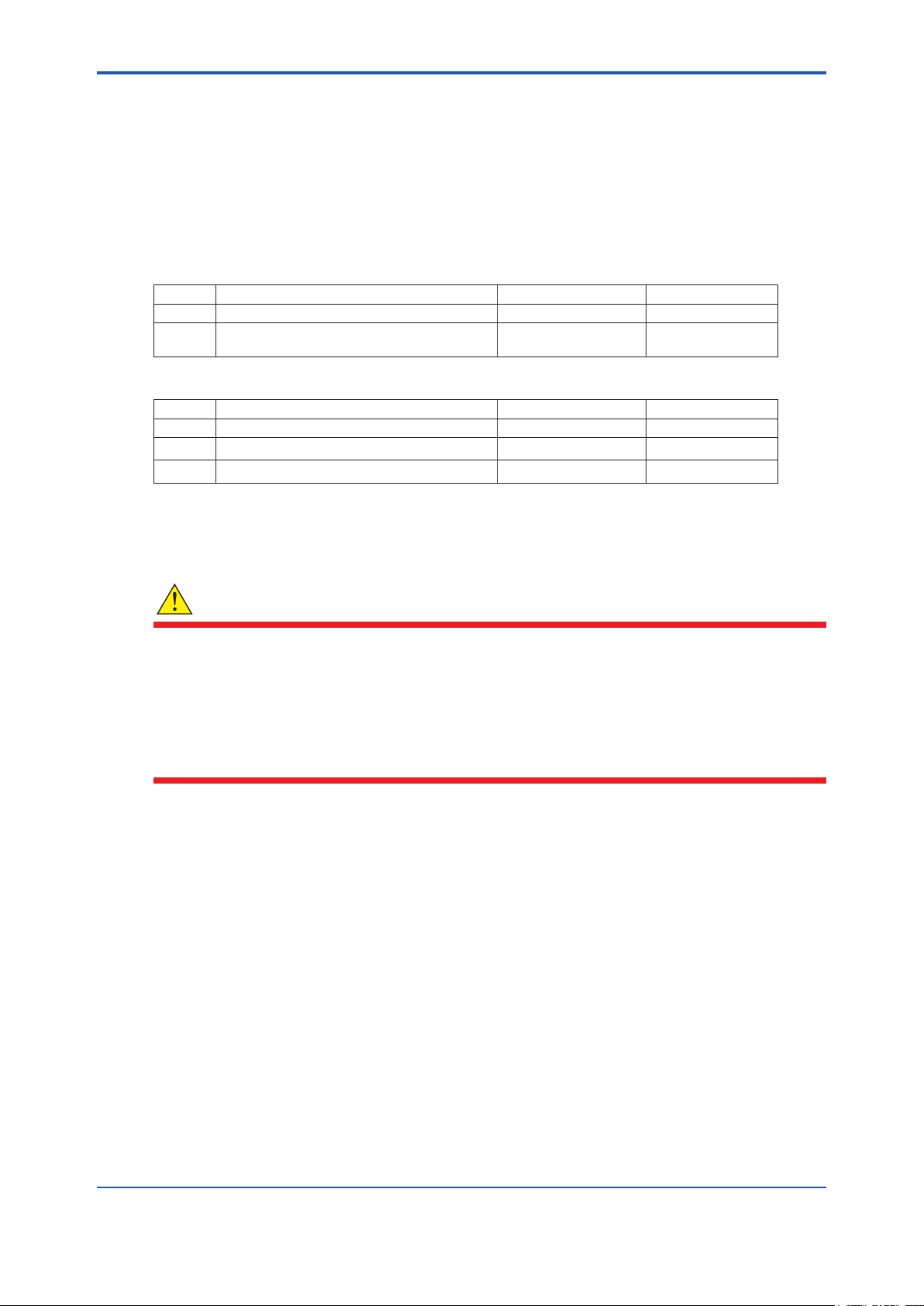
The related documents are as follows.
General Specications
Model Contents Document number Note
IR202 Infrared Gas Analyzer GS 11G02Q02-01EN
IR400
The “E” or “EN” in the document number is the language code.
User’s Manual
Model Contents Document number Note
ZX8D Zirconia Oxygen Analyzer IM 11G00E01-01EN (This manual)
IR202 Infrared Gas Analyzer IM 11G02Q02-01EN
IR400 Infrared Gas Analyzer IM 11G02N01-01E
The “E” or “EN” in the document number is the language code.
An exclusive User’s Manual might be attached to the products whose sux codes or option
codes contain the code “Z” (made to customers’ specications). Please read it along with this
manual.
NDIR TYPE INFRARED GAS ANALYZER
(5-COMPONENT ANALYZER)
i
GS 11G02N01-01E
WARNING
• This unit is not explosion-proof type. Do not use it in a place with explosive gases to prevent
explosion, re or other serious accidents.
• When noxious gases such as CO or other gases are contained in the calibration gas, be
careful when venting or handling the instrument to avoid poisoning.
• When combustible gases are contained in measuring gas, check the gas composition and
instrument specications before use, or else the best performance may not be obtained or
there may be a danger of explosion.
Media No. IM 11G00E01-01EN 6th Edition : May 2018 (YK)
All Rights Reserved Copyright © 2016, Yokogawa Electric Corporation
IM 11G00E01-01EN 6th Edition : May. 21, 2018-00
Page 3

ii
CAUTION
• This unit should be installed in a place which conforms to the conditions noted in the
instruction manual. Otherwise, it may cause electric shocks, re or malfunction of the unit.
• During installation work, care should be taken to keep the unit free from entry of cable chips
or other foreign objects. Otherwise, it may cause re, trouble or malfunction of the unit.
• The unit must be earthed as specied. Otherwise, it may cause electric shocks, malfunction,
etc.
• Be sure to use a power supply of correct rating. Connection of power supply of incorrect
rating may cause re.
• Wiring work must be performed with all the power supplies to OFF to prevent electric
shocks.
• Use wiring materials that match the rating of the unit. Use of wiring materials out of rating
may cause re.
• Wiring at a place which is exposed to water or rain, is prohibited in order to prevent electrical
shock or damage to the instrument.
• To avoid electrical shock, be sure to turn OFF the source power supply before work.
• To prevent burning your hands, be sure to turn OFF the source power supply before
cleaning the piping outlet. After power o, wait until the piping outlet cools down.
• Beware of acid uid inside the pipe. If acid uid should contact your skin or clothes,
immediately wash them with large amount of tap water. If they should splash onto your
eyes, seek medical attention at once.
• Do not use replacement parts other than those specied by the maker. Otherwise intended
performance may not be obtained, or accidents or faults may result.
• Replacement parts such as a maintenance part should be disposed of as incombustibles.
• If the cause of any fault cannot be determined despite reference to the instruction
manual, be sure to contact local sales representative or service oce. If the instrument is
disassembled carelessly, you may have a shock hazard or injury.
• Do not use a replacement part other than specied by the instrument maker. Otherwise,
adequate performance will not be provided. Besides, an accident or fault may be caused.
l Specication check
When the instrument arrives, unpack the package with care and check that the instrument
has not been damaged during transportation. In addition, please check that the specication
matches the order, and required accessories are not missing. Specications can be
checked by the model codes on the nameplate. Refer to Chapter 2 Specications for the list
of model codes.
IM 11G00E01-01EN 6th Edition : May. 21, 2018-00
Page 4
u Safety Precautions
n Safety, Protection, and Modication of the Product
• In order to protect the system controlled by the product and the product itself and ensure
safe operation, observe the safety precautions described in this user’s manual. We assume
no liability for safety if users fail to observe these instructions when operating the product.
• If this instrument is used in a manner not specied in this user’s manual, the protection
provided by this instrument may be impaired.
• If any protection or safety circuit is required for the system controlled by the product or for
the product itself, prepare it separately.
• Be sure to use the spare parts approved by Yokogawa Electric Corporation (hereafter
simply referred to as YOKOGAWA) when replacing parts or consumables.
• Modication of the product is strictly prohibited.
• The following safety symbols are used on the product as well as in this manual.
WARNING
This symbol indicates that an operator must follow the instructions laid out in this manual in order
to avoid the risks, for the human body, of injury, electric shock, or fatalities. The manual describes
what special care the operator must take to avoid such risks.
iii
CAUTION
This symbol indicates that the operator must refer to the instructions in this manual in order to
prevent the instrument (hardware) or software from being damaged, or a system failure from
occurring.
CAUTION
This symbol gives information essential for understanding the operations and functions.
NOTE
This symbol indicates information that complements the present topic.
n Warning and Disclaimer
The product is provided on an “as is” basis. YOKOGAWA shall have neither liability nor
responsibility to any person or entity with respect to any direct or indirect loss or damage arising
from using the product or any defect of the product that YOKOGAWA can not predict in advance.
IM 11G00E01-01EN 6th Edition : May. 21, 2018-00
Page 5

n Notes on Handling User’s Manuals
• Please hand over the user’s manuals to your end users so that they can keep the user’s
manuals on hand for convenient reference.
• Please read the information thoroughly before using the product.
• The purpose of these user’s manuals is not to warrant that the product is well suited to any
particular purpose but rather to describe the functional details of the product.
• No part of the user’s manuals may be transferred or reproduced without prior written
consent from YOKOGAWA.
• YOKOGAWA reserves the right to make improvements in the user’s manuals and product at
any time, without notice or obligation.
• If you have any questions, or you nd mistakes or omissions in the user’s manuals, please
contact our sales representative or your local distributor.
n Drawing Conventions
Some drawings may be partially emphasized, simplied, or omitted, for the convenience of
description.
Some screen images depicted in the user’s manual may have dierent display positions or
character types (e.g., the upper / lower case). Also note that some of the images contained in this
user’s manual are display examples.
iv
n Product Disposal:
The instrument should be disposed of in accordance with local and national legislation/regulations.
n Trademark Acknowledgments
• All other company and product names mentioned in this user’s manual are trademarks or
registered trademarks of their respective companies.
• We do not use TM or ® mark to indicate those trademarks or registered trademarks in this
user’s manual.
IM 11G00E01-01EN 6th Edition : May. 21, 2018-00
Page 6

u CE marking products
n Authorized Representative in EEA
The Authorized Representative for this product in EEA is Yokogawa Europe B.V. (Euroweg 2,
3825 HD Amersfoort, The Netherlands).
n Identication Tag
This manual and the identication tag attached on a packing box are essential parts of the
product. Keep them together in a safe place for future reference.
n Users
This product is designed to be used by a person with specialized knowledge.
n Information of the WEEE Directive
This product is purposely designed to be used in a large scale xed installations only and,
therefore, is out of scope of the WEEE Directive. The WEEE Directive does not apply. This
product should be disposed in accordance with local and national legislation/regulations.
The WEEE Directive is only valid in the EU.
v
IM 11G00E01-01EN 6th Edition : May. 21, 2018-00
Page 7

Blank Page
Page 8

Model ZX8D
Zirconia Oxygen Analyzer
IM 11G00E01-01EN 6th Edition
CONTENTS
u Introduction ....................................................................................................i
u Safety Precautions ......................................................................................iii
u CE marking products ..................................................................................v
1. Overview ........................................................................................................1
2. Specications ...............................................................................................2
3. Name and Description of Each Part ...........................................................4
4. Installation .....................................................................................................5
4.1 Mounting method ................................................................................................. 5
4.2 Piping .................................................................................................................... 6
4.3 Sampling ............................................................................................................... 7
4.4 Wiring method ...................................................................................................... 8
Toc-1
5. Operation .......................................................................................................9
5.1 Operating procedure ........................................................................................... 9
5.2 Preparation for operation .................................................................................... 9
5.3 Start of measurement .......................................................................................... 9
5.4 Shutdown .............................................................................................................. 9
6. Maintenance ............................................................................................... 10
6.1 Daily inspection .................................................................................................. 10
6.2 Cleaning gas outlet ............................................................................................ 11
6.3 Replacement of fuse .......................................................................................... 12
6.4 Output characteristic ......................................................................................... 12
Revision Information ...............................................................................................i
IM 11G00E01-01EN 6th Edition : May. 21, 2018-00
Page 9

Blank Page
Page 10

1. Overview
The zirconia oxygen analyzer utilizes a solid electrolyte consisting mainly of zirconia (ZrO2) which
conducts only oxygen ions at a high temperature. It is an oxygen sensor which measures, based
on the principle of an oxygen concentration cell, the electromotive force produced due to the
dierence in oxygen concentration between the measured gas and reference air. By combining
this analyzer with a sampling system including an infrared gas analyzer, it can accurately
measure oxygen concentration for a variety of applications including combustion equipment
control, air separation plants and laboratory use.
1
IM 11G00E01-01EN 6th Edition : May. 21, 2018-00
Page 11

2. Specications
Measuring system: Zirconia solid electrolyte
Measuring system: Zirconia solid electrolyte
Measuring range: Minimum range 0 to 5 vol% O
vol% O
Measurable component:
Output signal: 4 to 20mA DC and 0 to 1V DC linear connected to infrared gas
Sensor output:
Temperature alarm output: Contact output normally-closed contact,
Flow rate:
NOTE : The Zirconia system, due to its principle, may produce a measuring error due to relative concentration versus the
combustible O
sensor.
Warm up time: Approx. 30 minutes
Ambient temperature: 0 to +45°C
Ambient humidity: 90% RH or less
Use environment: Indoors
Mounting method: Indoor wall mounting
Gas inlet/outlet: Rc1/4 or 1/4NPT
Enclosure: Steel casing
Indication: Temperature indication (LED)
Outer dimensions (H×W×D): 141×170×190 mm
Mass: Approx. 3 kg
Finish color: Munsell 5Y7/1
Power supply
Rated voltage: 100 to 115 V AC or 200 to 240V AC
Rated frequency: 50 Hz/60 Hz
Power consumption: Max. 215 W. Approx. 65 W for ordinary use.
Fluctuation of power supply voltage: 230V AC ±10%
Repeatability: ±0.5% FS (when connected with infrared gas analyzer)
Linearity: Within ± 1% of full scale
Zero drift: Within ± 1% of full scale/week
Span drift: Within ± 2% of full scale/week
Response speed: Approx. 20 seconds for 90% response
Oxygen in noncombustible gas or combustion exhaust gas
(sensor will be burned and error will appear if combustible gas is
mixed in sample gas)
analyzer or direct output from sensor of the ZX8D.
Logical output of zirconia sensor (with sensor temperature of 800°C)
E = 50.74 log
Contact capacity: 220V AC, 1A (resistive load)
0.5±0.25 liter/minute (when connected with infrared gas analyzer)
gas concentration. Also, a corrosive gas (SO2 of 250 ppm or more, etc.) may aect the life of the
2
(when connected with infrared gas analyzer)
and maximum range of 0 to 25
, if used in combination with infrared gas analyzer
2
20.6
– B
X
2
E: Logical output (mV)
X: Measured gas concentration (%O
B: Blank voltage (mV)
2
)
2
IM 11G00E01-01EN 6th Edition : May. 21, 2018-00
Page 12

Safety, EMC and RoHS conforming standards (Only ZX8D-□*D)
Installation altitude: 2000 m or less
Pollution degree: 2
Installation category: II
Note: Installation category, called overvoltage category, species impulse withstanding voltage. Category II is for electrical
equipment. Pollution degree indicates the degree of existence of solid, liquid, gas or other inclusions which reduce
dielectric strength. Degree 2 is the normal indoor environment.
Safety: EN61010-1
EMC: EN61326-1 Class A, Table 2 (For use in industrial locations), EN61326-2-3,
EN61000-3-2, EN61000-3-3
EMC Regulatory Arrangement in Australia and New Zealand
Korea Electromagnetic Conformity Standard Class A
Note: The product mounted in a steel enclosure conforms to the requirements of EMC directive.
한국 전자파적합성 기준
3
Caution: The instrument is a Class A product, and it is designed for use in the industrial environment. Please use this
instrument in the industrial environment only.
RoHS: EN50581
Information of the WEEE Directive
This product is purposely designed to be used in a large scale xed installations only and,
therefore, is out of scope of the WEEE Directive. The WEEE Directive does not apply.
The WEEE Directive is only valid in the EU.
n Model and Sux codes
Model Sux code Option code Description
ZX8D - - - - - - - - - - - - - - - - - - - - - Zirconia Oxygen Analyzer
Power supply -3
-5
Style code *C*D- - - - - - - - - - -
- - - - - - - - - - -
- - - - - - - - - - -
- - - - - - - - - - -
200−240 V AC, 50/60 Hz
100−115 V AC, 50/60 Hz
For IR202, IR400
For IR202, IR400 (CE conformity)
IM 11G00E01-01EN 6th Edition : May. 21, 2018-00
Page 13

3. Name and Description of Each Part
n Name and description of each part on case
1
2 8
OXYGEN ANALYZER
9
TEMP.
4
2
3 4 5 6 72
1
AC250V
T3.15A
S
U
E
F
L
N
AC
INPUT
OUT
ALM
2
4 5 6 73
Front view
No. Name Function
1 Case cover Protects the internal components.
2 Retaining screw Fix the case cover.
3 Main switch Turn ON to supply power to the interior.
4 Fuse 250V AC/3.15A
5 Terminal board Used to connect input/output
6 Sample gas inlet Connect tube for gas to be measured.
(Rc1/4 internal thread or 1/4NPT internal thread)
7 Sample gas outlet Connect tube for discharging measured gas.
(Rc1/4 internal thread or 1/4NPT internal thread)
8 Temperature indicator Indicates the sensor temperature.
9 Specication nameplate Indicates type and specications.
n Name and description of internal parts
13
Side view
F0301.ai
12
10
11
F0302.ai
No. Name Function
10 Oxygen sensor Provides output according to oxygen concentration in sample gas.
11 Temperature controller Controls heater of oxygen sensor at operating temperature of 800°C.
12 Relay Control relay for heater.
13 Gas feeding case Introduces gas to be measured to the oxygen sensor.
IM 11G00E01-01EN 6th Edition : May. 21, 2018-00
Page 14

4. Installation
WARNING
This unit is not explosion-proof type. Do not use it in a place with explosive gases to prevent
explosion, re or other serious accidents.
CAUTION
This unit should be installed in a place which conforms to the conditions noted in the instruction
manual. Otherwise, it may cause electric shocks, re or malfunction of the unit.
4.1 Mounting method
OXYGEN ANALYZER
141
TEMP.
3 4 5 6 72
1
AC250V
T3.15A
S
U
E
F
L
N
AC
OUT
INPUT
110
ALM
150 or
more
5
Unit: mm
170
190
4-M4
150 or more
150 or more
OXYGEN ANALYZER
131
152
TEMP.
3 4 5 6 72
1
AC250V
T3.15A
S
U
E
F
L
N
AC
ALM
OUT
INPUT
150 or moreMounting dimensions
F0401.ai
Maintenance space
• Mount the unit on a metal plate, such as steel plate, of more than 3 mm thick using M4
screws or bolts. Do not mount it on materials such as plasterboard or lumber, which do not
have sucient strength for mounting. If the unit is to be mounted on a metal plate of less
than 3 mm thick, it is recommended to x the unit using nuts.
• Mount on a vertical wall with the gas inlet and outlet facing down.
• Provide space for maintenance and heat dissipation at the top, bottom, front and right side.
• To protect the oxygen sensor, avoid supplying power with the front of the unit facing upward.
• Select a proper installation location.
• Select a place where temperature will not uctuate too much, and remains near the normal
temperature and humidity.
• Select a place which is free from heat radiation or direct sunlight.
IM 11G00E01-01EN 6th Edition : May. 21, 2018-00
Page 15

• This analyzer is of an indoor structure. When installing outdoors, select a place which is not
exposed to rain or water or use a protective cover.
• Select a clean place which is free from corrosive gas or combustible gas.
4.2 Piping
Connect pipes to the gas inlet and outlet at the bottom of the unit.
Use anticorrosive tubes such as Teon, stainless steel or polyethylene for connecting this
instrument and the sampling system.
The inlet pipe should be kept as short as possible to allow a fast response. A suitable inner
diameter is around 4 mm. The pipes and joints should be clean, because dust entering the
instrument may cause faulty operation.
Since sulfuric acid mist or oxides may be discharged through the outlet pipe, this pipe should
have an inner diameter of about 8mm and be easily detachable for cleaning. A branch should
also be provided midway on this pipe for eliminating mist and the like. The outlet pipe should be
open to the atmosphere to avoid connecting it to another analyzer, sampling device, etc.
6
Sample gas inlet
(Rc1/4 or 1/4NPT):
Connect pipe here for
introducing gas to be measured.
37
OUTLET
23
Sample gas outlet
(Rc1/4 or 1/4NPT):
Connect pipe here for discharging measured gas.
n Piping conguration diagram
Following is a typical example of piping.
Check
Sample gas
Permapure dryer
valve Filter
Oxygan
analyzer
INLET
48
Bottom view
Flowmeter
F0402.ai
Infrared gas
analyzer
Inlet
Outlet
Changeover
valve
Inlet
Water
sealed
Exhaust
(open to
atmosphere)
NO SO2Air O2/N
(Standard gas)
IM 11G00E01-01EN 6th Edition : May. 21, 2018-00
2
F0403.ai
Page 16

4.3 Sampling
WARNING
• This unit is not explosion-proof type. Do not use it in a place with explosive gases to prevent
explosion, re or other serious accidents.
• When combustible gases are contained in measuring gas, check the gas composition and
instrument specications before use, or else the best performance may not be obtained or
there may be a danger of explosion.
n Sample gas conditions
• Dust included in sample gas should be completely eliminated with a lter. Use a lter
capable of eliminating dust particles of 0.3 μm at the nal stage.
• The dew point of sample gas must be lower than the ambient temperature to avoid
condensation of drain inside the analyzer. If water vapor is included in sample gas, then use
a dehumidier to lower the dew point to about 0°C.
• If SO
• Strongly corrosive gases like Cl
• Sample gas temperature should range from 0 to 50°C. Do not introduce a high temperature
• Combustible gases such as H
mist is included in sample gas, then use a mist lter, cooler or the like to exclude it.
3
Other types of mist should also be excluded.
life of the instrument. Harmful components such as Si vapor, alkaline metals, P, Pb and SO
at high concentrations (1000ppm or more) will also shorten its service life.
gas directly into the instrument.
reaction and produce a measuring error.
, F2 and HCl included in sample gas will shorten the service
2
and CO included in sample gas will consume O2 via a
2
7
2
n Sample gas ow rate
Set the sample gas ow rate at 0.5±0.25 L/min.
n Preparation of standard gas
Prepare standard gas for zero point and span calibration.
Zero gas (span gas in rule of measuring) Air
Span gas (zero gas in rule of measuring) 1 to 2% O
2/N2
IM 11G00E01-01EN 6th Edition : May. 21, 2018-00
Page 17

4.4 Wiring method
Ground terminal
CAUTION
• Wiring work must be performed with all the power supplies to OFF to prevent electric
shocks.
• Be sure to perform class D grounding. Otherwise electric shock or malfunction may result.
• During installation work, care should be taken to keep the unit free from entry of cable chips
or other foreign objects. Otherwise, it may cause re, trouble or malfunction of the unit.
• Use wiring materials that match the rating of the unit. Use of the wiring materials out of rating
may cause electric shocks or re.
• Be sure to use a power supply of correct rating. Connection of power supply of incorrect
rating may cause re.
• Wiring at a place which is exposed to water or rain, is prohibited in order to prevent electrical
shock or damage to the instrument.
External terminals are provided on the front of the instrument. Make connection to these
terminals according to Figure 4.1. Be sure to perform class D grounding.
Terminal screws are M4. Keep the power supply wiring to 3 m or shorter, and use a polyvinyl
chloride wire of 1.25 sq for 600V or equivalent.
Use shielded wiring for the output signal to reduce the inuence of external noise.
8
Oxygen analyzer
1 2 3 4 5 6 7
+ –
Power supply:
100 V or
220 V AC
50/60 Hz,
approx.
200 VA
Figure 4.1 External wiring
Output from
zirconia
detector
Temperature
alarm setting
±20°C
Infrared gas analyzer
F0404.ai
IM 11G00E01-01EN 6th Edition : May. 21, 2018-00
Page 18

5. Operation
WARNING
• When noxious gases such as CO or other gases are contained in the calibration gas, be
careful when venting or handling the instrument to avoid poisoning.
• When combustible gases are contained in measuring gas, check the gas composition and
instrument specications before use, or else the best performance may not be obtained or
there may be a danger of explosion.
CAUTION
• Do not use a replacement part other than specied by the instrument maker. Otherwise,
adequate performance will not be provided. Besides, an accident or fault may be caused.
• Wiring at a place which is exposed to water or rain, is prohibited in order to prevent electrical
shock or damage to the instrument.
9
5.1 Operating procedure
Read through the instruction manual for the infrared gas analyzer to be combined with this
analyzer, then proceed to operation accordingly.
The oxygen analyzer requires a warmup of at least 30 minutes.
5.2 Preparation for operation
(1) Check of piping and wiring
Make sure all the piping and wiring have been made correctly.
(2) Turning on power
Turn on the power switch and the temperature will be indicated.
(3) Warmup
Flow zero gas (air) and warm up the instrument for at least 30 minutes. The warmup is
nished when the temperature reaches 800±5°C.
(4) Calibration
Calibrate the zero point (air) and span with reference to the instruction manual for the
infrared gas analyzer.
5.3 Start of measurement
Flow the sample gas into the instrument.
5.4 Shutdown
When shutting down the instrument, supply air or the like for at least 5 minutes to replace the
measured gas inside the sensor.
The turn OFF the power switch.
IM 11G00E01-01EN 6th Edition : May. 21, 2018-00
Page 19

6. Maintenance
WARNING
When noxious gases such as CO or other gases are contained in the calibration gas, be careful
when venting or handling the instrument to avoid poisoning.
CAUTION
• If the cause of any fault cannot be determined despite reference to the instruction
manual, be sure to contact local sales representative or service oce. If the instrument is
disassembled carelessly, you may have a shock hazard or injury.
• To avoid electrical shock, be sure to turn OFF the source power supply before work.
• To prevent burning your hands, be sure to turn OFF the source power supply before
cleaning the piping outlet. After power o, wait until the piping outlet cools down.
• Do not use replacement parts other than those specied by the maker. Otherwise intended
performance may not be obtained, or accidents or faults may result.
• Replacement parts such as a maintenance part should be disposed of as incombustibles.
• Do not use a replacement part other than specied by the instrument maker. Otherwise,
adequate performance will not be provided. Besides, an accident or fault may be caused.
• Wiring at a place which is exposed to water or rain, is prohibited in order to prevent electrical
shock or damage to the instrument.
10
6.1 Daily inspection
n Zero point (air) and span calibration
(1) Calibrate the zero point according to the instruction manual for the infrared gas analyzer.
(2) Calibrate the span following zero point calibration.
(3) Zero point and span should be calibrated about once a week as required.
n Check of ow rate
Check once a day if sample gas ow rate is 0.5±0.25 L/min.
n Check of analyzer output and temperature indication
l Oxygen analyzer output
If the response is delayed or the oxygen indication does not change, then check for disconnected
piping or clogging of the outlet pipe, etc.
l Temperature indication
• Check if the temperature indication is in a range of 800±5°C.
• If the temperature indicator shows “UUUU”, then wiring may be disconnected or a
thermocouple may be broken.
IM 11G00E01-01EN 6th Edition : May. 21, 2018-00
Page 20

Check for continuity between 3 and 4 of the oxygen sensor - it should be around 2Ω.
When disconnected, replace the oxygen detector.
6.2 Cleaning gas outlet
Sulfate mist or oxide may be precipitated at the pipe output, depending on the components of
measuring gas.
11
Gas introduction case
Gas outlet pipe
Gas outlet joint
Detector mounting screw
Packing
Gas inlet joint
Zr detector
Zr detector external terminal block
F0601.aiBushing for gas outlet
Clean the pipe according to the following procedure.
(1) After supplying atmospheric air or N2 standard gas for at least 5 minutes in the oxygen
analyzer, set the power supply and main unit power supply switch to OFF.
(2) Remove the inlet pipe of oxygen analyzer, and exhaust the gas to outside.
Beware of ventilation when sample gas contains a toxic component such as CO or SO2.
(3) Remove the outlet pipe and bushing of oxygen analyzer. Place a drain receiver on the
bottom part.
CAUTION
Beware of acid uid inside the pipe. If acid uid should contact your skin or clothes, immediately
wash them with large amount of tap water. If they should splash onto your eyes, seek medical
attention at once.
(4) Eliminate and clean the precipitates inside the gas outlet pipe with driver or absorbent
cotton. Be careful not to damage the tip of detector.
(5) Reconnect the pipe as before, paying attention not to cause gas leakage. Check the
indication of ow meter.
(6) Turn on the power switch and warm up oxygen analyzer.
IM 11G00E01-01EN 6th Edition : May. 21, 2018-00
Page 21

6.3 Replacement of fuse
CAUTION
Be sure to nd the cause of the blowout and take necessary measures before replacing the fuse.
(1) Turn o the power switch.
(2) The fuse is located at the lower left viewed from the front. Pull up the cap of the fuse holder
while rotating it counterclockwise, and the cap and the fuse are detached.
(3) Replace the fuse with a new one (Fuse: 250V AC / 3.15A delay type).
(4) Then fasten the cap of the fuse holder.
OXYGEN ANALYZER
TEMP.
12
3 4 5 6 72
U
F
AC250V
T3.15A
S
E
1
L
AC
INPUT
N
OUT
ALM
F0602.aiFuse holder (Cap)
6.4 Output characteristic
Table 1 ZX8D output characteristic
OUTPUT (mV)
%O
2
0.01
0.02
0.03
0.04
0.05
0.1
0.2
0.3
0.4
0.5
0.6
0.7
0.8
0.9
1.0
2.0
3.0
4.0
5.0
6.0
E (OUTPUT: mV) = 50.74 log 21/O2%
168.57 7.0 24.21
153.3 8.0 21.27
144.36 9.0 18.67
138.02 10.0 16.35
133.1 11.0 14.25
117.83 12.0 12.33
102.56 13.0 10.57
93.62 14.0 8.93
87.28 15.0 7.41
82.36 16.0 5.99
78.35 17.0 4.66
74.95 18.0 3.40
72.01 19.0 2.21
69.41 20.0 1.08
67.09 20.6 0.4238
51.82 21.0 0
42.88 22.0 -1.025
36.54 23.0 -2.005
31.62 24.0 -2.943
27.61 25.0 -3.84
%O
2
OUTPUT (mV)
IM 11G00E01-01EN 6th Edition : May. 21, 2018-00
Page 22

Revision Information
l Manual Title : Model ZX8D Zirconia Oxygen Analyzer
l Manual No. : IM 11G00E01-01EN
May 2018 / 6th Edition
Added WEEE directive information. (p.v, p.3)
Deleted IR200 (p.i, p.3)
Corrected errors (p.3)
Nov. 2017 / 5th Edition
Revised a description on power supply. (p.2)
Aug. 2017 / 4th Edition
Added RoHS. (p.3)
June 2017 / 3rd Edition
Revised due to the discontinuation of IR250.(p.i, p.3) for a model change into IR202.
Mar. 2017 / 2nd Edition
Added IR250 with some revision and so forth. (p.i,p.v, p.2, p.3, p.5)
i
Feb. 2016 / 1st Edition
Newly published
Yokogawa Electric Corporation
2-9-32 Nakacho, Musashino-shi, Tokyo 180-8750, JAPAN
http://www.yokogawa.com/
IM 11G00E01-01EN 6th Edition : May. 21, 2018-00
Page 23

Blank Page
 Loading...