

Page 1

User’s
Manual
Model ZR22P
High Temperature Adapter
IM 11M12A01-01E-A
IM 11M12A01-01E-A
1st Edition
Page 2

Page 3

ZR22P High Temperature Adapter
INTRODUCTIONI. ......................................................................................................... 4
OVERVIEWII. ..................................................................................................................4
SPECIFICATIONSIII. ........................................................................................................ 5
INSTALLATIONIV. ............................................................................................................ 7
4.1 Installation ..........................................................................................................................................7
4.1.1 Location ..........................................................................................................................................7
4.1.2 Adapter Insertion Point ...................................................................................................................7
4.1.3 Adapter Insertion and Process Flange Preparation ........................................................................7
4.2 Mounting the ZR22G Detector to the ZR22P High Temperature Adapter .........................................8
4.2.1 Installation Location ........................................................................................................................8
4.3 Usage of the ZR22P High Temperature Probe Adapter ....................................................................9
PIPINGV. ....................................................................................................................... 11
5.1 Piping to the High Temperature Probe Adapter ...............................................................................11
5.2 Mounting the Auxiliary Eductor ........................................................................................................11
5.3 Piping Parts for the ZR22P ..............................................................................................................12
EDUCTOR OPTIONSVI. ................................................................................................ 13
6.1 Air Eductor, Pre-Attached with Regulator and Gauge (/BE Option) .................................................13
6.1.2 Air Source .....................................................................................................................................13
6.2 Air Eductor, Exhaust Return (/ER Option) ........................................................................................14
6.3 Separate Air Eductor, NOT Pre-Attached (/SE Option) ...................................................................15
Automatic Blowback Option (/AV)VII. .......................................................................... 16
7.1 Principle of Operation ......................................................................................................................16
7.2 Piping to the split adapter ................................................................................................................16
7.2.1 Block Valve with Actuator ...................................................................................................16
7.2.2 Blowback Air ......................................................................................................................16
7.3 Wiring to the ZR402G for Blowback ................................................................................................16
7.3.1 Adapter Tee Blowback Control ...........................................................................................16
7.3.2 Operation of the ZR22P Control .........................................................................................17
7.3.3 Blowback Timing Sequence ...............................................................................................17
Maintenance and Trouble ShootingVIII. ........................................................................19
8.1 Maintenance ....................................................................................................................................19
8.2 Trouble Shooting ..............................................................................................................................19
8.3 Maintenance for Air Eductor Return ................................................................................................21
APPENDIX A, Dimensional Drawings ........................................................................23
APPENDIX B, Wiring Diagrams .................................................................................27
APPENDIX C, Spare Parts ........................................................................................ 31
Page 4

4
ZR22P High Temperature Adapter
INTRODUCTION1.
The purpose of the ZR22P High Temperature Adapter is to accommodate the ZR22 series of Zirconia Oxygen
Detectors for use in process gas temperatures that exceed 700ºC (1292 ºF). The adapter is also used in high
temperature applications that are subject to frequent plugging or clogging, such as lime kilns, or fuels with high
particulate loading.
OVERVIEW2.
The ZR22P High Temperature Adapter uses air pressure to draw a sample away from the process and cool
the process sample to a temperature below 700C. This allows the Zirconia oxygen detector to operate
safely away from the high temperatures that would otherwise damage the probe, heater and cell assembly.
The ZR22P Probe can be designed to accommodate the varying needs of the process sample. For negative
process pressures, the High Temperature Adapter can be tted with an air eductor to draw the sample from
the primary process and bring it to the ZR22G detector.
Several models of the ZR22P are available for different applications and environments. For ordering
information and part numbers, please refer to the Oxygen Selection Guide.
IM 11M12A01-01E-A
Page 5

ZR22P High Temperature Probe Adapter
ZR22P SPECIFICATIONS3.
The ZR22P is available in several variations, with multiple options. Additionally, this high temperature oxygen
probe adapter can be customized to meet the customer’s needs. There are three types of material, depending
upon sample temperature, which can be used for the transport tube. Additionally, there are varying transport
lengths available:
Construction: Rainproof, non explosion-proof construction.
Installation: Flange mounted
Installation Flange:
ANSI Class, 150#, 4 inch RF ange, SUS304 1.
ZR22G probe side, JIS 5K32A, FF ange 2.
Insertion Length: 0.3 meter (11.8 in) to 3.0 meter (9.84 ft), or no transport tube (-NNN).
Sample gas temperature: 700°C (1292°F) to 1871°C (3400°F).
5
Material in contact with the process gases:
Silicon Carbide (SiC), for temperatures up to 1427°C (2600°F)1.
310 Stainless Steel, for temperatures up to 1082°C (1980°F)2.
Alumina Ceramic, for temperatures up to 1871°C (3400°F)3.
Zirconia/Platinum cell4.
SUS 304 (ange)5.
The actual weight of the ZR22P High Temperature Adapter will vary with material selection, installed options and
transport tube length.
IM 11M12A01-01E-A
Page 6
6
Model Notes
ZR22P High Temperature Probe Adapter
Tee Conguration
-H Basic Design (Side Eductor Port)
-T Basic Design (Bottom Port)
-S Split Design (For Blowback)
Transport Tube Material
-A Silicon Carbide (SIC). Up to 2600°F / 1427°C
-B 310 S Stainless Steel. Up to 1980°F / 1082°C
-C Alumina Ceramic. Up to 3400°F / 1871°C
-N No Transport Tube
Insertion Length
-033 0.3 meter (11. 8”)
-050 0.5 meter (18”)
-100 1.0 meter (3’ 3”)
-150 1.5 meter (4’ 11”)
-300
3.0 meter (9’ 10”) Requires Probe Support or
Protector
-NNN No Transport Tube
Flange Connection
-C*U ANSI 4.0 inch, 150# FF Flange
Option: Heater System
/HT Aux heater system (to 600°F). Incl. controller & heater
Option: Blowback Valve
/AV Automatic valve (Only with ZR22P-S)
Option: Eductor
/BE
/ER
Heated air eductor pre-attached with regulator & gauge
Cannot be used with /HT, /AV of -F.
Air ejector with return exhaust pre-attached with
regulator & gauge.
/SE Separate air ejector, regulator (NOT pre-attached)
/SCT Stainless Steel tag plate
IM 11M12A01-01E-A
Page 7

4. Installation
4.1 Installation
4.1.1 Location
The following should be taken into consideration when installing the High Temperature Adapter and
Oxygen Detector:
Easy and safe access to the adapter and detector for maintenance.1.
Ambient temperature of not more than 150ºC (302ºF), and the detector terminal box should not be 2.
affected by radiant heat.
A clean environment without corrosive gases.3.
CAUTION
A natural convection type detector (model ZR22G), which uses ambient air as a reference gas, requires
that the ambient air concentration be constant. Clean, dry instrument air is recommended for quality
and accurate measurement.
4. No or extremely low vibration.
5. The measurement gas satises the specications described in Chapter 2 of the ZR22G Instruction
Manual, IM 11M12A01-02E.
6. No measured gas pressure uctuations
7
4.1.2 Adapter Insertion Point
When preparing the insertion point, the following should be taken into consideration:
CAUTION
If the detector is mounted horizontally, the calibration and reference gas inlets on the ZR22G Probe •
should face downwards
The sensor (Zirconia cell) at the probe tip may be damaged due to thermal shock if water drops are •
allowed to accumulate on it, as it is always at high temperature.
When using an adapter with an eductor return, ensure that the gasket material does not interfere with the •
eductor return port on the adapter ange.
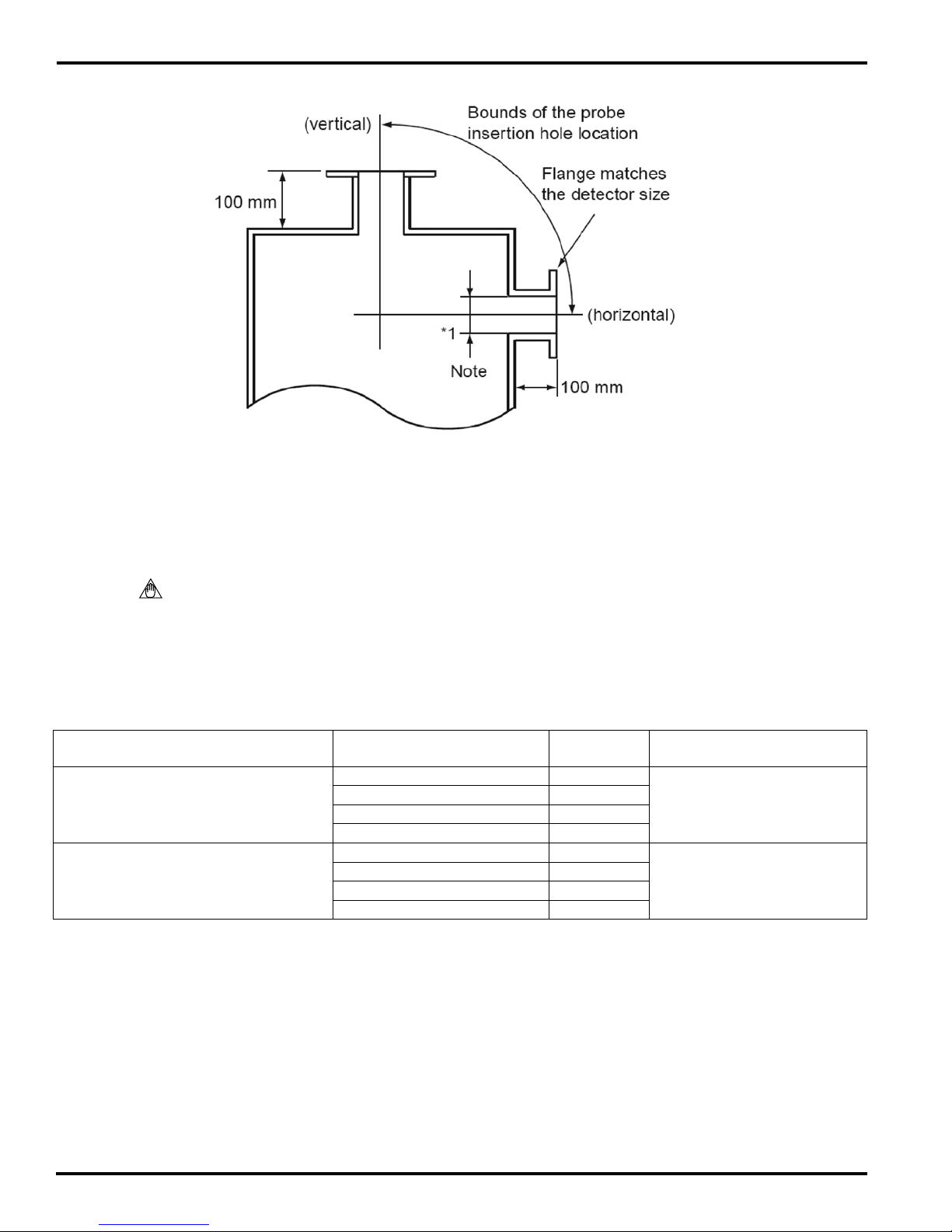
4.1.3 Adapter Insertion and Process Flange Preparation
When forming the adapter insertion hole, the following should be taken into consideration:
Ensure that the insertion point has an equal ange type (ANSI 4.0 inch, 150# FF Flange), with proper 1.
bolt hole spacing and diameter.
The distance between the process wall and the process ange should be 100mm (4.0 inches) or 2.
more, as shown in Figure 4.1.
Attach the transport tube (if provided) to the ange base of the adapter prior to installing the ZR22P.3.
CAUTION
The weight of the adapter and probe combined can weigh up to 100 lbs. It is recommended that •
the ZR22P adapter be installed WITHOUT the ZR22G detector to avoid damaging the entire unit.
Use caution when lifting and positioning the adapter and probe into place. Utilize lifting devices, •
and or a two person lift when available.
IM 11M12A01-01E-A
Page 8
8
Figure 4.1
4.2 Installation of the Detector (Model ZR22G-015-Q)
Note: Ceramic (Zirconia) is used in the sensor (cell) portion of the detector probe. Care should be
taken to not drop the detector during installation. The same applies to the High Temperature Adapter
transport tube.
A gasket should be used on the ange surface to prevent gas leakage. The gasket material should be
selected depending on the characteristics of the measured process sample gas. It should be heat and
corrosion resistant to the sample temperatures and gases present. These parts are to be supplied by
the user, and are described in Table 4.1.
Mounting Flange Specication Accessory Name Quantity Note
ZR22G-015 Probe
JIS 5K32A Flange
ZR22P Adapter to Process
ANSI 4.0 inch 150# FF Flange
*Specications for gasket material(s) vary, and are dependent upon process application. A local pipetting
distributor can assist with proper selection of gasket materials
*Gasket 1
Bolt (M12 x 50) 4
Nut (M12) 4
Washer (M12) 8
*Gasket 1
Bolt (M16x 60) 8
Nut(M16) 8
Washer (M16) 16
Table 4.1
Heat and Corrosion Resistant
Heat and Corrosion Resistant
4.2.1 Installation Location
The ZR22G-015-Q model detector is used with the ZR22P High Temperature Probe Adapter, when
sample gas temperatures exceed 700ºC (1292ºF). Additionally, this detector can be utilized where
maintenance space is limited.
IM 11M12A01-01E-A
Page 9
The installation requirements of the ZR22G Zirconia Oxygen Detector should be consistent with
the procedures outline in Section 4.1. Further installation instructions can be found in the ZR22G
Instruction manual IM 11M12A01-02E, Chapter 3.
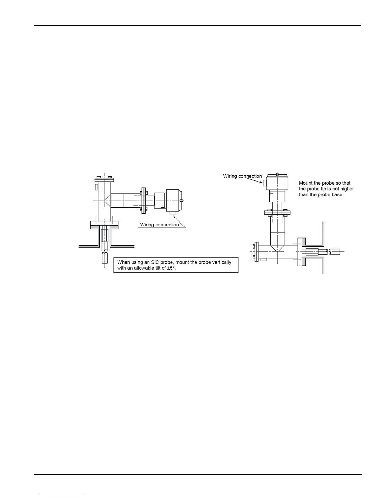
It is recommended that the detector be mounted vertically. If it is necessary to mount the 1.
detector horizontally, ensure that the probe tip is placed no higher that the probe base. Figure
4.2.
When installing the high temperature probe adapter, be sure to insert a gasket between the 2.
anges to prevent gas leakage, Table 4.1. When the process pressure is negative, ensure that
there is no leakage of air into the process.
When mounting the detector in a position other than vertical, the cable inlet should face 3.
downward.
When installing the detector in a low ambient temperature location, such as in cool open air, 4.
cover the probe adapter including the eductor with a heat insulator (e.g. ceramic wool) to keep
the assembly warm. This will help to prevent condensation from entering the eductor and probe.
9
Figure 4.2
4.3 Usage of the ZR22P High Temperature Probe Adapter
During analysis, the surface temperature of the probe adapter should be within the range from the
dew point of the measured gas to prevent eductor clogging, gasket deterioration and bolt scoring.
Where the dew point of the measured gas is not known, keep within the range of 200ºC to 300ºC
(392ºF to 592ºF).
The temperature shall be measured at the probe in the probe adapter and the surface of the blind
ange at the opposite side.
When the surface temperature is not within the above specied range, the following measures can
be taken to change the temperature:
(1) When the surface temperature exceeds 300ºC (572ºF):
When the process pressure is negative, lower the pressure setting to reduce induction a.
of the sample gas. Refer to section 6.1 of this manual for setting of induction ow. When
IM 11M12A01-01E-A
Page 10

10
the induction ow is reduced, ensure that the eductor inducts air when the process
pressure uctuates.
When the process pressure is positive, close the needle valve for the sample gas outlet b.
to reduce exhaust gas ow. Refer to section 5.1 for piping instructions.
When the probe adapter is surrounded by a heat insulator, remove the insulation. Ensure c.
that the temperature of the probe adapter does not fall below the dew point of the gas in
winter conditions.
To prevent temperature rises due to radiant heat, insert a heat insulator between the d.
process wall and the probe adapter.
To prevent temperature rises from thermal conduction, place the mounting ange as far e.
from the process wall as possible (4” min).
(2) When the surface temperature is less than 200ºC (392ºF):
When the process pressure is negative, raise the eductor air pressure to increase a.
induction ow of the measurement gas. Refer to section 6.1 of this manual for setting of
induction ow. Excessive dust may accumulate, and the eductor may clog if induction
ow increases.
When the process pressure is positive, open the needle valve for the sample gas outlet b.
to increase the gas ow.
Warm the probe adapter. Refer to Appendix A for instructions relating to the /HT Heated c.
Air Eductor Option. Ensure that the temperature does not drop below freezing point.
When the surface is still less than 200ºC (392ºF) or below the dew point of the measured d.
gas regardless if the above measure have been taken, warm the adapter with an
external; heat source such as steam.
IM 11M12A01-01E-A
Page 11
5. Piping
5.1 Piping to the High Temperature Probe Adapter
The measured gas should be at a temperature below 700°C (1292°F) before reaching the •
detector sensor. If the gas is under negative pressure, it should be fed to the detector by suction.
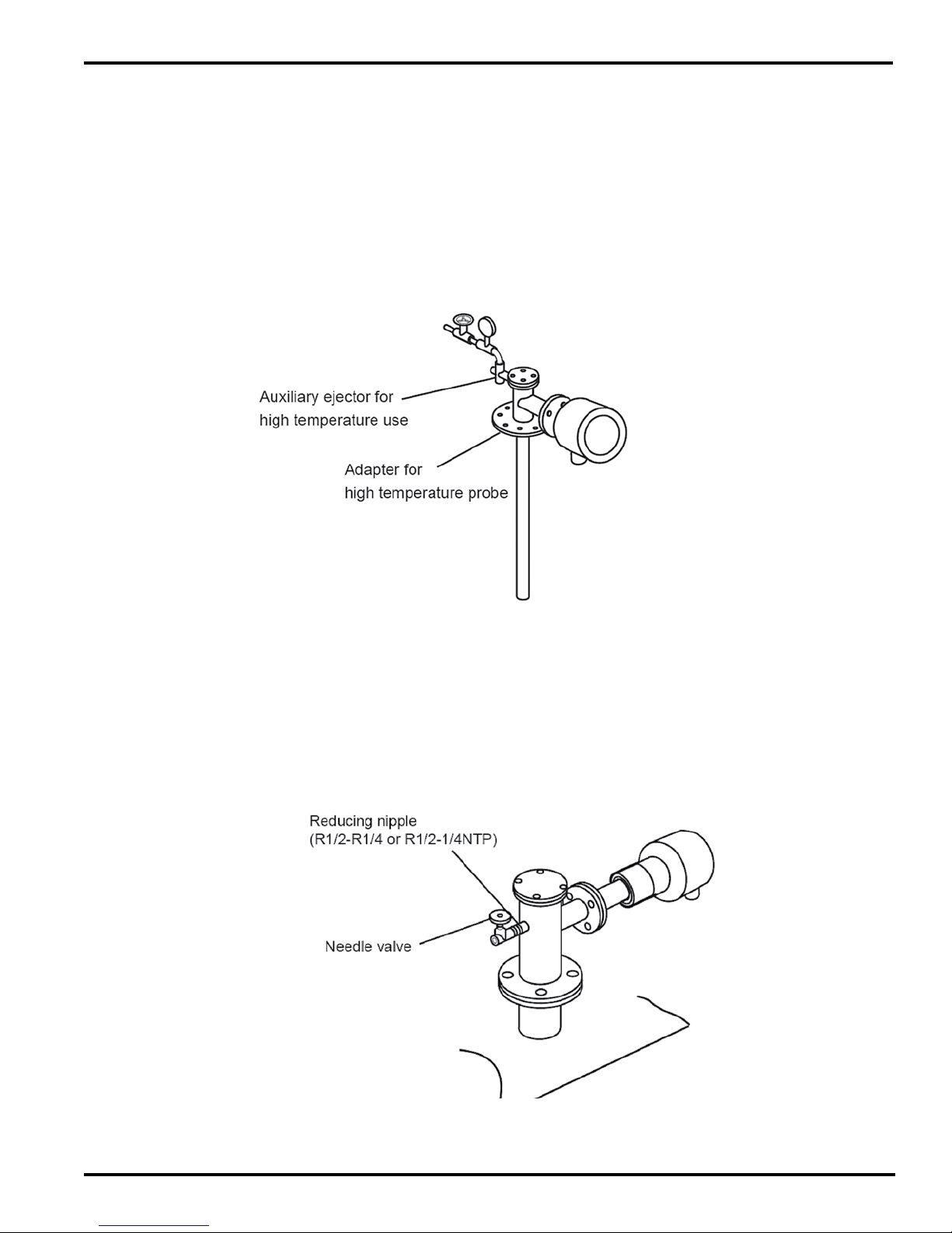
If the measured gas is under negative pressure, connect the auxiliary eductor as illustrated in •
Figure 5.1. Mount the pressure gauge as close as possible to the auxiliary eductor. However, if
the ambient temperature is too high, mount the gauge in a location with an ambient temperature
below 40ºC (104 ºF).
11
Figure 5.1 Mounting the Auxiliary Eductor
5.2 Mounting the Auxiliary Eductor
If the temperature of the sample gas exceeds the specied value and its pressure exceeds 0.49
kPa, the sample gas temperature may not fall below 700°C (1292°F) at the detector. In such a case,
connect a needle valve through a nipple to the probe adapter sample gas exhaust, so that the
sample gas exhaust volume is restricted. For additional eductor options, refer to chapter 6 of this
manual.
Figure 5.2 Mounting the needle valve for restricting exhaust ow
IM 11M12A01-01E-A
Page 12

12
In cases where condensation is likely to occur when the sample gas is cooled, protect the probe adapter
with an insulating material as illustrated in Figure 5.3. Ensure that adequate space is left for probe and air line
maintenance.
Figure 5.3 Preventing condensation
5.3 Piping Parts for the ZR22P
Detector
High Temperature
Detector
Piping
Location
Calibration
Gas Inlet
Reference
gas inlet
Sample
Gas outlet
Parts Notes
Check valve
Nipple* Rc 1/4 or ¼ inch NPT General parts
Zero Gas Cylinder User’s Scope
Gas Pressure
Regulator
Joint for tube
connection
Auxiliary Eductor*
Reducing nipple*
Recommended by Yokogawa:
(M1234VV-A). Available through Yokogawa
Recommended by Yokogawa: M1132KD
Regulator, and M1132ME Gauge.
Available through Yokogawa
Rc 1/4 or ¼ inch NPT General parts
Recommended by Yokogawa:
M1132KA, Stainless Steel Eductor
M1234WR-A, Teon Eductor (for high
particle applications)
Rc ¼ or ¼ inch
NPT R ½ to R ¼ or
R ½ to ¼ inch NPT
General parts
* Parts are used when required.
** General parts can be purchased on the open market.
IM 11M12A01-01E-A
Table 5.1
Page 13

6. Eductor Options
The Eductor option(s) are used to draw the sample through the high temperature adapter when the process
pressure is negative.
6.1 Air Eductor, Pre-Attached with Regulator and Gauge (/BE Option).*
*This option cannot be used with the /HT or /AV options.
Note: The /BE option is a pre-attached, pre-heated instrument air connection. This eductor option
pre-heats the instrument air via convective heat from the adapter. As contact heat from the process
gases heat the adapter, the convective heat raises the temperature of the instrument air. The
purpose for heating the instrument air is to prevent condensation build up from clogging the eductor.
Refer to Figure 6.1. The process gases are then vented to atmosphere, instead of being piped back
into the process. Additional dimensions can be found in Appendix B.
13
6.1.2
Clean dry instrument air should be used to prevent condensation, and allows for a more accurate
measurement. A general purpose air regulator should be used to adjust the ow of instrument air
entering the eductor. The Yokogawa model M1132KD Pressure Regulator is recommended for use
with this application. Refer to Table 5.1 for applicable tubing and connections.
Note: * Flow to the eductor should not exceed the recommended air supply of 20 psig.
Note: ** The /BE Eductor Option cannot be used with the /HT or /AV Options.
Figure 6.1 ZR22P…/BE
IM 11M12A01-01E-A
Page 14

14
6.2 Air Eductor, Exhaust Return (/ER Option).*
*This option cannot be used with the /HT option.
Note: The /ER option has pre-attached instrument air piped to the adapter to draw the sample up to
the probe. The eductor creates a vacuum, which draws the sample through the transport tube and
past the ZR22G Probe. The process gases are then piped back into the process through the adapter
ange. See Figure 6.2. The air supply to the eductor is fed through a 1/8” NPT internal connection.
Plumbing to the eductor is customer supplied. Clean, dry instrument air should be used for this
application at a pressure no greater than 20 psi.
The components that make the eductor return include the air eductor, regulator and gauge; however,
the regulator and gauge are remote from the unit.
Figure 6.2 Eductor Return (/ER Option)
IM 11M12A01-01E-A
Page 15

Figure 6.3 M1132KA Stainless Steel Air Eductor
6.3 Separate Air Eductor, Not Attached, (/SE Option)
15
The Separate Eductor option is a standard High Temperature Adapter that allows the customer to
supply their own air source and eductor. The High temperature adapter is threaded for ¼” FNPT
connection.
Figure 6.4 Separate Eductor Option (/SE)
IM 11M12A01-01E-A
Page 16

16
7. Automatic Blowback Option (/AV)
7.1 Principle of Operation
This option should be chosen when there is a probability of process particles clogging the sampling
system. The design consists of an automatic blowback valve and solenoid that is activated by the
ZR402G Single Channel Oxygen Analyzer or the AV550G Multi-Channel Oxygen Averaging Unit.
The actuator uses a 4-way, 2 position single solenoid valve with a double acting air actuator.
The automated valve closes when blowback is initiated, thereby isolating the detector during
blowback operations. The actuator is electrically controlled by a solenoid, which is pre-wired
from the factory.
NOTE: This option requires a ZR22P-S split design ange.
NOTE: The /AV option is NOT suitable for Hazardous Area Classication.
7.2 Piping to the split adapter
7.2.1 Block Valve with Actuator
The actuator requires 80 psi (60psi minimum) of clean dry instrument air. Attach ¼” stainless
steel tubing to the ¼” FNPT tting of the blowback solenoid. The tubing between the solenoid
and actuator is prefabricated at the factory. The block valve is controlled by a single solenoid,
where the valve closes when the solenoid is energized and opens when deenergized.
7.2.2 Blowback Air
The blowback air solenoid uses between 60 psi and 80 psi of clean dry instrument air. Attach
¼” stainless steel tubing to the ¼” FNPT tting of the blowback solenoid, which is mounted at
the ZR22P adapter.
7.3 Wiring to the ZR402G for blowback
NOTE: Run separate conduit for heater and signal wiring.
NOTE: For additional information regarding set up procedures for the ZR40G and blowback
sequence refer to the ZR402G Instruction Manual IM11M12A01-02E, Chap10.2
Heater output: 14AWG, 1 twisted pair (2 conductor) with shield terminated at the converter•
Signal output: 16 AWG, 3 twisted pair (6 conductors) with the shield terminated at the converter.•
Less that 10 ohms total loop resistance• .
For additional wiring details, refer to the wiring diagrams in Appendix .
7.3.1 Adapter Tee Blowback Control
The user provides power supply input to the ZR22P. The Cable should meet all NEC codes for 115
VAC, 10A supply. The user also provides a 14 AWG, 2 conductor cable from the ZR402G to the
ZR22P.
IM 11M12A01-01E-A
Page 17

Two (2) band heaters are pre-attached and pre-wired to a heater controller, mounted in a NEMA 4X
enclosure at the ZR22P adapter. The temperature controller is factory set for a high alarm set point
of 700°F. If this alarm set point is exceeded, the controller will shut off the power to the heaters.
A Type J thermocouple is included to maintain the temperature of the adapter at approximately
600°F. The solenoid valves that control the overall blowback system are also prewired. Two separate
limit switches are used to control the eductor solenoid and the blowback solenoids. The limit
switches are mounted in a separate enclosure
Eductor Solenoid Normally Open (NO)
Block Valve Normally Open (NO)
Blowback Air Solenoid Normally Closed (NC)
The end user must provide contact closure to input #1, terminals 13 & 15 to the ZR402G in order to
initiate blowback.
7.3.2 Operation of the ZR22P Control
The ZR22P has a separate electrical control circuit mounted at the adapter tee for blowback control.
Standard operation of this unit requires connection to the ZR402G Oxygen Analyzer contact output
#3.When the ZR402G initiates a blowback sequence (after a contact closure to contact input #1),
the blocking valve will close, the eductor valve will close, and the blowback air valve will be pulsed
by the ZR402G contact output. The pressure switch is preset to 0.7 psi on fall, which will prevent
the opening of the block valve if there is any pressure trapped in the transport tube due to an
unsuccessful blowback. When the blowback air cycle is nished and all the pressure has returned to
less than 0.7 psi, the blocking valve will open and the eductor valve will open. See the sequence of
events in chart 7.1.
17
NOTE: When Relay 3 is activated, Heaters #1 and #2 are disabled. Relay#3 latches ON until 115V
power is cycled OFF.
7.3.3 Blowback Timing Sequence
Event 1: Blowback is initiated with the contact closure from the ZR402G. Closure is at least 1
second.
Event 2: Block Valve is closed.
Event 3: Air Eductor is closed by the block A limit switch. The Air eductor cannot close unless event
2 has occurred.
Event 4: Blowback solenoid is pulsed at 10 second intervals, as received from the ZR402G contact
output. Although the actual pulse from the ZR402G occurs 2 seconds after the contact
closure, the air ow for blowback is briey delayed until Events 2 and 3 have occurred.
Event 5: Block valve opens after delay timer of 15 seconds lapses, and the pressure switch indicates
that the residual pressure blowback is normal (less than 0.7 psi).
Event 6: The air eductor is opened, so that air ows through the eductor. Sampling of the process
returns to normal.
The duration of the blowback pulse is determined by the Calibration Time programmed at the
ZR402G in menu C4. The block valve will remain closed because of the relay timer, which
is shipped with a preset time delay of 15 seconds. The timer is not adjustable. At the end of
the blowback time (as set in the C4 menu), and the time delay, the block valve will open and
the air eductor solenoid will open.
NOTE: Blowback should only be performed as needed, as extreme blowback frequency will cause a
long stabilization time for reading to return to normal levels after blowback.
IM 11M12A01-01E-A
Page 18

18
Chart 7.1 Blowback Timing Sequence
IM 11M12A01-01E-A
Page 19

Maintenance and Trouble Shooting
8.1 Maintenance
The High Temperature Adapter is structured so that the gas to be measured is directed the detector
with the high temperature probe adapter. Therefore, if the probe or the sample gas outlet clogs,
a precise measurement is no longer possible, as the gas ow is signicantly reduced. If a high
temperature adapter/detector combination is used, it must be inspected periodically and cleaned if
any part of the assembly becomes clogged with dust or particulates.
Dust found sticking to the probe itself should be blown off using low pressure compressed air, or
use a soft cloth with distilled water. For maintenance, inspection and cleaning of the ZR22G Oxygen
Detector please refer to instruction manual IM 11M12A01-02E, Chapter 11.
Should any dust or particulate remains after the initial cleaning, attempt to remove the contaminant
with a metal rod or metallic brush. A removable port (blank-off plate) is located at the top of the
high temperature adapter for cleaning the internal portion of the high temperature adapter and the
transport tube area.
19
If dust or heavy particulate is found in the eductor assembly, remove the eductor and blow out the
contaminant with low pressure compressed air or rinse with distilled water.
CAUTION: DO NOT use water to clean any parts of the High Temperature Adapter or ZR22G
Oxygen Detector that are used in Lime Kiln operations.
8.2 Troubleshooting
Problem 1: Block valve remains closed after blowback cycle is ended, and a pressure build up
has occurred.
Possible cause(s): The pressure switch attached to the blowback inlet has given a contact to the
system to keep the valve closed in order to protect the probe from damage.
To remove a pressure build up:
1. Turn off air supply to the eductor
2. Slowly loosen the tting at the blowback inlet connection to allow the pressure to bleed off.
CAUTION: Process gases may be extremely hot. Use caution when loosening the tting on the
blowback connection.
3. Remove power from the ZR402G or AV550G blowback circuitry.
4. Tighten the tting at the blowback inlet, so that a leak does not occur. A leak will cause a high
reading during normal operations.
5. Remove the blind ange and gasket, and manually clean out the transport tube as listed in section
8.1above.
6. Once the clog has been removed, replace the gasket and blind ange.
7. Return system to normal operation
IM 11M12A01-01E-A
Page 20

20
Problem 2: Oxygen reading is abnormally low during normal operation.
Possible cause(s): The transport tube may be clogged and the eductor is drawing a vacuum.
NOTE: Cell damage may occur from excessive vacuum pressures.
Solution:
1. Verify that air ow to the eductor is adequate to draw a sample. (Max. 20 psi)
2. Remove power from the analyzer and adapter tee.
3. Turn off air supply to the eductor.
4. Remove the probe from the adapter.
5. Visually inspect the cell assembly area of the ZR22G probe for dust/particulate clogging the cell
screen.
6. Remove the blind ange and gasket.
7. Ensure that the transport tube is not clogged. If no clog exists, turn on air supply to the eductor to
verify a sample is being drawn.
8. Place all components, ensuring replacement of the gasket.
9. Conrm reference air ow rate to the ZR22G probe is 0.8 LPM.
10. Return to normal operation
NOTE: If the problem persists, unburned hydrocarbons may be present. Additional cleaning and
disassembly of the ZR22G probe may be required.
Problem 3: Oxygen reading is abnormally high
Possible causes(s):
• Possible leaks within the system.
• Eductor may be clogged
• Blowback solenoid in “constant on” position.
Solutions:
1. Ensure the gaskets are properly installed.
2. Ensure that the probe calibration gas ttings are air tight. If the calibration gas port is not being
used, it must be tightly sealed, as to not allow air into the probe.
3. Remove eductor and check for clogging. If the eductor is found to be clogged, clean or replace
the eductor.
4. Ensure that the blowback solenoid programming is correct in the ZR402G, G2 menu.
Problem 4: Blowback solenoid remains ON
Solution:
1. Conrm proper programming at the ZR402G (or AV550G) for contact output #3 (G2 menu).
Problem 5: Air eductor is clogged
Solution:
1. Clean or replace the eductor (M1132KA).
NOTE: If a constant high amount of dust or particulate is present, a Teon eductor is available; Part
Number M1234WR-A.
Problem 6: Block valve does not close
Possible causes(s):
1. Conrm that at least at least 60 psi of air (80psi recommended) is attached to the solenoid for the
actuator.
2. Verify proper wiring
IM 11M12A01-01E-A
Page 21

8.3 Maintenance for Air Eductor Return
The following maintenance instructions are for the eductor return option only. The eductor and/or
the return piping may plug from time to time. The following is recommended for disassembling the
eductor and the return piping:
Remove power from the ZR22P control box by opening the fuse switch located on the terminal 1.
box, inside of the control box at the adapter tee.
Remove the insulation (if applicable) from the eductor return piping.2.
Conrm that power has been shut off before proceeding. Check the voltage at terminals 2 and 8.3.
Ensure that the air supply to the eductor has been turned off.4.
Remove the air supply from the eductor.5.
Loosen the band heaters screws. 6. CAUTION: DO NOT completely remove the screws from
the band heater. Additionally, it is not necessary to remove the wiring from the heater band.
Carefully detach the air eductor from the solenoid. Note: It is not necessary to remove the wiring 7.
from the solenoid.
Remove the ttings that secure the eductor to the piping. Slide the band heater off of the 8.
eductor.
21
IM 11M12A01-01E-A
Page 22

Page 23

23
APPENDIX A
Dimensional Drawings
IM 11M12A01-01E-A
Page 24

24
Note: Transport tube insertion lengths can vary upon customer requirements between 0.0m to 3.0m
IM 11M12A01-01E-A
ZR22P-H-A-100-C*U/SE
Page 25

25
Note: Transport tube insertion lengths can vary upon customer requirements between 0.0m to 3.0m
ZR22P-H-A-100-C*U/ER
IM 11M12A01-01E-A
Page 26

26
Note: Transport tube insertion lengths can vary upon customer requirements between 0.0m to 3.0m
IM 11M12A01-01E-A
ZR22P-H-A-150-C*U/BE
Page 27

27
APPENDIX B
Wiring Diagrams
IM 11M12A01-01E-A
Page 28

28
IM 11M12A01-01E-A
Page 29

29
IM 11M12A01-01E-A
Page 30

Page 31

31
APPENDIX C
Spare Parts
IM 11M12A01-01E-A
Page 32

32
Pressure Regulator, M1132KD
This general purpose regulator is used to adjust the pressure of the instrument air entering the air
eductor on the ZR22P.
Flow Capacity: 20 SCFM (33.6m/hr) at 100 psig supply – 20psig at outlet
Exhaust Capacity: 0.1 SCFM (0.17m/hr – downstream pressure 5 psig above setpoint
Sensitivity: 1” WC
Effect of Supply Pressure Variation: Less than 0.2 psig for 25 psi change
Maximum Supply Pressure: 250 psig
Air Consumption: Less than 6 SCFM
Output Range: 0 to 60 psi
Port size: ¼” NPT
Materials: Body – Die cast aluminum alloy
Diaphragm – Nitrile elastomer and nylon fabric
Trim – Brass, zinc plates steel, acetyl
Weight: 4.0 lbs (1.8 kg)
Pressure Gauge, M1132ME
Gauge Size: 2” (50mm)
Measuring Range: 0 to 60 psi
Connection: ¼” NPT
IM 11M12A01-01E-A
Page 33

Weight: 0.5 lbs (0.2 kg)
Air Eductor, M1132KA
Vacuum Force: 7.6” Hg
Vacuum Flow: 2 to 5 SCFM
Air Consumption: 1.7 SCFM
Recommended Air Supply: Up to 20 psi
Connections: Air Supply: 1/8” FNPT
Vacuum: ¼” MNPT
Exhaust: ¼” MNPT
Material: 316 SS
Weight: 6oz (170g)
33
IM 11M12A01-01E-A
Page 34

34
Thinband Heater, M1233LN (Eductor /ER option ONLY)
Power Supply: 120 VAC
Consumption: 100 Watts
Leads: 36” Type L high temp leads (2
3
/
” Diameter to 2 ½”wide)
8
Thinband Heater, M1133EC
Power Supply: 120 VAC
Consumption: 400W
Leads: 36” Type L high temp leads (2 ” Diameter to 2 ½”wide)
IM 11M12A01-01E-A
 Loading...