

Page 1
User's
Manual
Model AV550G
Zirconia Oxygen Analyzer
Averaging Converter
IM 11M12D01-01E
IM 11M12D01-01E
3rd Edition
Page 2
Introduction
The EXAxt Series AV550G Zirconia Oxygen Analyzer Averaging Converter is designed
for oxygen measurement at multiple points in flue ducts of industrial furnaces and can
be used to optimize the combustion process. For the AV550G system, various types of
EXAxt ZR Series detectors as well as optional accessories are available. The best
measurement can be achieved by selecting instruments appropriate to your application.
This manual provides information, such as installation, operation, inspection and
maintenance procedures, about the instruments used in the AV550G averaging converter
measurement system. Any sections concerning instruments not included in your system
may be skipped.
Before using the instruments, read any descriptions related to your instruments and
system to ensure the best performance.
Regarding the HART communication, refer to IM 11M12D01-51E. IM 11M12D01-51E
has been published as "Model EXAxt AV550G HART protocol."
Regarding the FOUNDATION Fieldbus communication, refer to IM 11M12D01-61E.
IM 11M12D01-61E has been published as "Model EXAxt AV550G Fieldbus
communication."
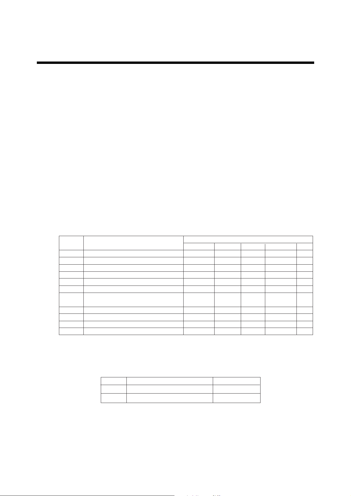
The models and description items in this manual are as follows:
Models and descriptions in this manual
Description in this manual
Model Product Name Specification Installation Operation Maintenance CMPL
ZR22G General-use detector s s s s s
ZR22G High-temperature detector (0.15m) s s s s
AV550G Averaging Converter s s s s s
ZO21R-L Probe protector s s
ZO21P-H High-temperature probe adapter s s s
ZA8F Flow setting unit (for manual calibration use) s s s
- Auxiliary ejector for high-temperature use
(Part No. E7046EC, EN) s s s
- Calibration gas unit case (Part No. E7044KF) s s
- Check valve (Part No. K9292DN, K9292DS) s s
- Dust filter for the detector (Part No. K9471UA) s s
- Dust guard protector (Part No. K9471UC) s s
CMPL : Customer Maintenance Parts List
T.Int.1E
User's manuals of instruments related to the AV550G Averaging Converter are as
follows:
Model
ZR22G
ZO21DW
Title
Separate Type Zirconia Oxygen Analyzer
In-Site Type Zirconia Oxygen Analyzer
Manual No.
IM 11M12A01-02E
IM 11M03A02-E
Tbl-01.eps
IM 11M12D01-01E
3rd Edition: Sep. 2005 (YK)
All Rights Reserved, Copyright © 2004, Yokogawa Electric Corporation
IM 11M12D01-01E
i
Page 3
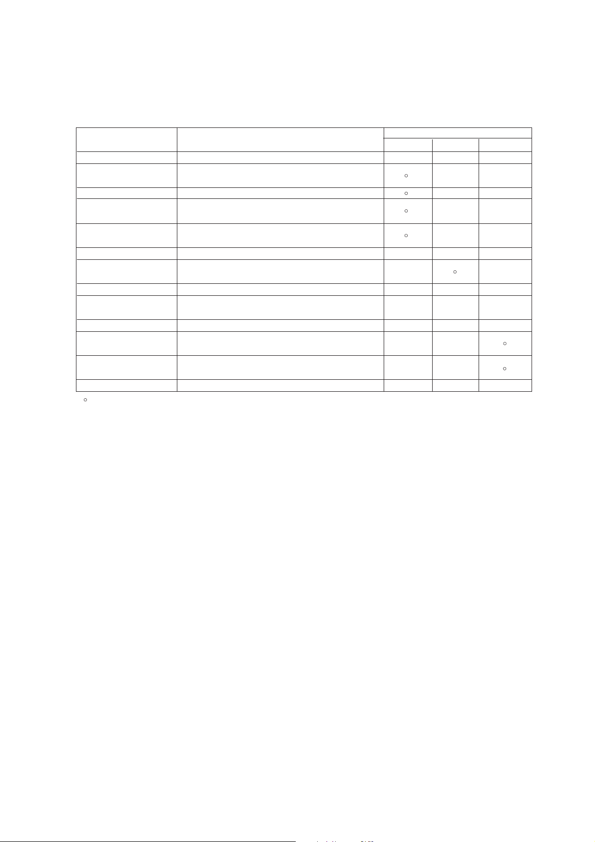
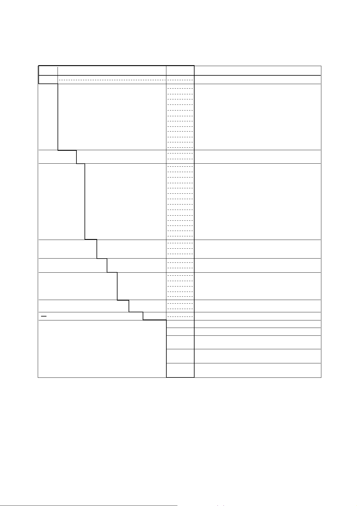
This manual consists of twelve chapters. Please refer to the reference chapters for
installation, operation and maintenance.
Table of Contents
Relates to
Chapter Outline Installation Operation Maintenance
1. Overview Equipment models and system configuration examples
2. Specifications Standard specification, model code (or part number),
dimension drawing for each equipment
3. Installation Installation method for each equipment
4. Piping Examples of piping in three standard system
configurations
5. Wiring Wiring procedures such as “Power supply wiring”, “output
signal wiring” or others
6. Components Major parts and function are described in this manual
7. Startup Basic procedure to start operation of AV550G. Chapter 7
enables you to operate the equipment immediately.
8. Detailed Data Setting Details of key operations and displays
9. Calibration Describes the calibration procedure required in the course
of operation.
10. Other Functions Other functions described
11. Inspection and How to conduct maintenance of AV550G and procedures
Maintenance for replacement of deteriorated parts
12. Troubleshooting This chapter describes measures to be taken when an
abnormal condition occurs.
CMPL (parts list) User replaceable parts list
: Read and completely understand before operating the equipment.
s
: Read before operating the equipment, and refer to it whenever necessary.
s
: Recommended to read it at least once.
n
s
s
s
s
s
n
n
s
s
s
s
s
s
s
n
n
s
s
n
n
n
s
n
n
n
n
s
s
s
T.Int.2E
ii
IM 11M12D01-01E
Page 4
r For the safe use of this equipment
CAUTION
The cell (sensor) at the tip of the detector is made of ceramic (zirconia element). Do not
drop the detector or subject it to pressure stress.
• Do NOT allow the sensor (probe tip) to make contact with anything when installing
the detector.
• Avoid any water dropping directly on the probe (sensor) of the detector when installing it.
• Check the calibration gas piping before introducing the calibration gas to ensure that
there is no leakage of the gas. If there is any leakage of the gas, the moisture drawn
from the measured gas may damage the sensor.
• The detector (especially at the tip) becomes very hot. Be sure to handle it with gloves.
DANGER
AV550G is very heavy. Handle it with care. Be sure not to accidentally drop it. Handle
safely to avoid injury.
Connect the power supply cord only after confirming that the supply voltage matches
the rating of this equipment. In addition, confirm that the power is switched off when
connecting power supply.
Some process gas is dangerous to people. When removing this equipment from the
process line for maintenance or other reasons, protect yourself from potential poisoning
by using a protective mask or ventilating the area well.
When carrying the AV550G Averaging Converter, mark sure this is done by two or
more people.
(1) About This Manual
• This manual should be passed on to the end user.
• The contents of this manual are subject to change without prior notice.
• The contents of this manual shall not be reproduced or copied, in part or in whole,
without permission.
• This manual explains the functions contained in this product, but does not warrant that
those will suit the particular purpose of the user.
• Every effort has been made to ensure accuracy in the preparation of this manual.
However, should any errors or omissions come to the attention of the user, please
contact the nearest Yokogawa Electric representative or sales office.
• This manual does not cover the special specifications. This manual may not be
changed on any change of specification, construction and parts when the change does
not affect the functions or performance of the product.
• If the product is used in a manner not specified in this manual, the safety of this
product may be impaired.
IM 11M12D01-01E
iii
Page 5
(2) Safety and Modification Precautions
• Follow the safety precautions in this manual when using the product to ensure protection and safety of personnel, product and system containing the product.
(3) The following safety symbols are used on the product as well as in this manual.
DANGER
This symbol indicates that the operator must follow the instructions laid out in this
manual in order to avoid the risk of personnel injury electric shock, or fatalities. The
manual describes what special care the operator must exercise to avoid such risks.
WARNING
This symbol indicates that the operator must refer to the instructions in this manual in
order to prevent the instrument (hardware) or software from being damaged, or a system
failure from occurring.
CAUTION
This symbol draws attention to information essential for understanding the operation and
functions.
Tip
This symbol gives information that complements the present topic.
SEE ALSO
This symbol identifies a source to which to refer.
Protective Conductor Terminal
Function Earth Terminal (Do not use this terminal as the protective conductor
terminal.)
Alternating current
iv
IM 11M12D01-01E
Page 6

• Special descriptions in this manual
This manual indicates operation keys, displays and drawings on the product as follows:
• Displays on the panel 0 0.
(Ex. message display 0 BASE 0)
(Ex. data display 0 1020 )
IM 11M12D01-01E
v
Page 7

r NOTICE
• Specification check
When the instrument arrives, unpack the package with care and check that the
instrument has not been damaged during transportation. In addition, please check that
the specification matches the order, and required accessories are not missing. Specifications can be checked by the model codes on the nameplate. Refer to Chapter 2
Specifications for the list of model codes.
• Details on operation parameters
When the AV550G Averaging Converter arrives at the user site, it will operate based
on the operation parameters (initial data) set before shipping from the factory.
Ensure that the initial data is suitable for the operation conditions before conducting
analysis. Where necessary, set the instrument parameters for appropriate operation.
For details of setting data, refer to chapters 7 to 10.
When user changes the operation parameter, it is recommended to note down the
changed setting data.
r After -Sales Warranty
d Do not modify the product.
d During the warranty period, for repair under warranty carry or send the product to the
local sales representative or service office. Yokogawa will replace or repair any
damaged parts and return the product to you.
d Before returning a product for repair under warranty, provide us with the model
name and serial number and a description of the problem. Any diagrams or data
explaining the problem would also be appreciated.
d If we replace the product with a new one, we won’t provide you with a repair report.
d Yokogawa warrants the product for the period stated in the pre-purchase quotation.
Yokogawa shall conduct defined warranty service based on its standard. When the
customer site is located outside of the service area, a fee for dispatching the maintenance engineer will be charged to the customer.
d In the following cases, customer will be charged repair fee regardless of warranty
period.
• Failure of components which are out of scope of warranty stated in instruction
manual.
• Failure caused by usage of software, hardware or auxiliary equipment, which
Yokogawa Electric did not supply.
• Failure due to improper or insufficient maintenance by user.
• Failure due to modification, misuse or outside-of-specifications operation which
Yokogawa does not authorize.
• Failure due to power supply (voltage, frequency) being outside specifications or
abnormal.
• Failure caused by any usage out of scope of recommended usage.
• Any damage from fire, earthquake, storms and floods, lightning, disturbances, riots,
warfare, radiation and other natural changes.
vi
IM 11M12D01-01E
Page 8

d Yokogawa does not warrant conformance with the specific application at the user
site. Yokogawa will not bear direct/indirect responsibility for damage due to a specific
application.
d Yokogawa Electric will not bear responsibility when the user configures the product
into systems or resells the product.
d Maintenance service and supplying repair parts will be covered for five years after
the production ends. For repair for this product, please contact the nearest sales office
described in this instruction manual.
IM 11M12D01-01E
vii
Page 9

viii
IM 11M12D01-01E
Page 10

Contents
Introduction........................................................................................................................... i
r For the safe use of this equipment .......................................................................... iii
r NOTICE ....................................................................................................................vi
r After-Sales Warranty................................................................................................vi
1. Overview ....................................................................................................................... 1-1
1.1 System Configuration...................................................................................... 1-1
1.1.1 System Configuration Using Flow Setting Units for Manual Calibration1-1
1.1.2 System Configuration to Perform Automatic Calibration ...................... 1-2
1.2 System Components........................................................................................ 1-3
1.2.1 System Components and Their Applicability ......................................... 1-3
1.2.2 Detectors and Accessories....................................................................... 1-3
2. Specifications ................................................................................................................2-1
2.1 General Specifications .................................................................................... 2-1
2.1.1 Standard Specifications ........................................................................... 2-1
2.2 General-use Separate-type Detector and Related Equipment ........................ 2-3
2.2.1 ZR22G General-use Separate-type Detector........................................... 2-3
2.2.2 ZO21R-L Probe Protector ....................................................................... 2-8
2.3 High-Temperature Separate-type Detector and Related Equipment.............. 2-9
2.3.1 ZR22G (0.15m) High-Temperature Separate-type Detector .................. 2-9
2.3.2 ZO21P-H Adapter for High-Temperature Probe .................................. 2-10
2.4 AV550G Averaging Converter ..................................................................... 2-12
2.4.1 Standard Specification ........................................................................... 2-12
2.4.2 Functions................................................................................................ 2-13
2.5 ZA8F Flow Setting Unit ............................................................................... 2-19
2.5.1 ZA8F Flow Setting Unit ........................................................................ 2-19
2.6 Other Equipment ........................................................................................... 2-21
2.6.1 Dust Filter for the Detector (Part No.: K9471UA)............................... 2-21
2.6.2 Dust Guard Protector (Part No.: K9471UC)......................................... 2-21
2.6.3 Auxiliary Ejector for High Temperature
(Part No. E7046EC or E7046EN)........................................................ 2-22
2.6.4 Stop Valve (Part No. L9852CB or G7016XH) .................................... 2-24
2.6.5 Check Valve (Part No. K9292DN or K9292DS) ................................. 2-25
2.6.6 Air Set.................................................................................................... 2-26
2.6.7 Zero Gas Cylinder (Part No. G7001ZC)............................................... 2-28
2.6.8 Cylinder Regulator Valve (Part No. G7013XF or G7014XF) ............. 2-28
2.6.9 Calibration Gas Unit Case (Part No. E7044KF) .................................. 2-29
2.6.10 Model ZR22A Heater Assembly........................................................... 2-30
3. Installation ....................................................................................................................3-1
3.1 Installation of the Detector ............................................................................. 3-1
3.1.1 Location ................................................................................................... 3-1
3.1.2 Probe Insertion Hole................................................................................ 3-1
3.1.3 Installation of the Detector...................................................................... 3-2
3.1.4 Installation of the Dust Filter( Part No K9471UA), etc ......................... 3-3
3.1.5 Procedures for installing the dust guard protector (K9471UC).............. 3-4
3.1.6 Detector with a probe protector
(Model ZO21R-L-hhh-h *B for enhance forth ................................ 3-4
viii
IM 11M12D01-01E
Page 11

3.1.7 Detector with a probe protector
(Model ZO21R-L-hhh-h *B for dust wear protect............................ 3-5
3.2 Installation of the Detector (Model ZR22G-015) ........................................... 3-6
3.2.1 Installation Location ................................................................................ 3-6
3.2.2 Usage of the High-temperature Probe Adapter (Model ZO21P-H) ....... 3-6
3.2.3 Probe Insertion Hole................................................................................ 3-7
3.2.4 Mounting of the High-Temperature Detector ......................................... 3-8
3.3 Installation of the Averaging Converter ......................................................... 3-9
3.3.1 Installation Location .............................................................................. 3-10
3.3.2 Installation in an Instrument Panel ....................................................... 3-10
3.3.3 Outdoor Installation............................................................................. 3-12
3.4 Installation of ZA8F Flow Setting Unit ....................................................... 3-13
3.4.1 Location ................................................................................................. 3-13
3.4.2 Mounting of ZA8F Flow Setting Unit .................................................. 3-13
3.5 Installation of the Calibration Gas Unit Case .............................................. 3-15
3.5.1 Location ................................................................................................. 3-15
3.5.2 Mounting................................................................................................ 3-15
4. Piping............................................................................................................................. 4-1
4.1 Piping for a System Using Flow Setting Units for Manual Calibration ........ 4-1
4.1.1 Parts Required for Piping in a System Using Flow Setting Units
for Manual Calibration ............................................................................ 4-3
4.1.2 Piping for the Calibration Gases ............................................................. 4-3
4.1.3 Piping for the Reference Gas .................................................................. 4-4
4.1.4 Piping to the High Temperature Probe Adapter ..................................... 4-4
4.1.5 Piping for Blowback................................................................................ 4-6
4.1.6 Piping for Indication check ..................................................................... 4-7
4.1.7 Piping to Introduce Purge Gas When a Process Gas Alarm Occurs...... 4-8
4.2 Piping for a System to Perform Automatic Calibration................................. 4-9
4.2.1 Parts Required for Piping in a System to Perform Automatic
Calibration ............................................................................................. 4-10
4.2.2 Piping for the Calibration Gases ........................................................... 4-11
4.2.3 Piping for the Reference Gas ................................................................ 4-12
4.2.4 Piping to the High Temperature Probe Adapter ................................... 4-12
4.2.5 Piping for Blowback............................................................................. 4-12
4.2.6 Piping for Indication Check ................................................................. 4-12
4.2.7 Piping to Introduce Purge Gas When a Process Gas Alarm Occurs.... 4-13
5. Wiring ........................................................................................................................... 5-1
5.1 General ............................................................................................................ 5-1
5.1.1 Wiring Precautions .................................................................................. 5-2
5.1.2 Wiring Holes ........................................................................................... 5-4
5.1.3 External Wiring Connection Terminals of the Averaging Converter .... 5-4
5.1.4 Types of Wiring and Cables ................................................................... 5-5
5.2 Wiring for the Averaging Converter and Peripheral Devices........................ 5-6
5.2.1 Preparation for Wiring to the Averaging Converter ............................... 5-6
5.2.2 Preparation for Wiring to Detectors........................................................ 5-6
5.2.3 Power and Ground Wiring ...................................................................... 5-8
5.2.4 Power Wiring to Detector Heaters .......................................................... 5-8
5.2.5 Signal Wiring to Detectors.................................................................... 5-10
5.2.6 Ground Wiring of Detectors .................................................................. 5-11
5.2.7 Wiring for Individual and Average Concentration Analog Outputs .... 5-12
IM 11M12D01-01E
ix
Page 12

5.2.8 Wiring for Solenoid Valve for Automatic Calibration ......................... 5-12
5.2.9 Wiring for Individual/Common Error Contact Outputs
and Common Contact Outputs .............................................................. 5-13
5.2.10 Wiring for Contact Inputs ..................................................................... 5-15
5.3 Wiring and Piping Examples ........................................................................ 5-16
5.3.1 Wiring and Piping for Automatic Calibration ...................................... 5-16
5.3.2 Wiring and Piping for Automatic Calibration and 3rd Gas Indication
Check ..................................................................................................... 5-16
5.3.3 Wiring and Piping for Blowback .......................................................... 5-17
5.3.4 Wiring and Piping for Automatic Calibration and Blowback .............. 5-17
6. Components ..................................................................................................................6-1
6.1 ZR22G Detector .............................................................................................. 6-1
6.1.1 General-purpose Detector (except for Model ZR22G-015) ................... 6-1
6.1.2 High-Temperature Detector (Model ZR22G-015).................................. 6-2
6.2 AV550G Averaging Converter ....................................................................... 6-3
6.2.1 Components and Function....................................................................... 6-3
6.2.2 Touchpanel Switch Operations ............................................................... 6-3
6.2.2.1 Panels and Switches ................................................................................ 6-3
6.2.2.2 Switches and Their Functions ................................................................. 6-5
6.2.2.3 Display Configuration ............................................................................. 6-6
6.2.2.4 Display Functions .................................................................................... 6-7
6.2.2.5 Entering Numeric and Text Data .......................................................... 6-10
6.3 ZA8F Flow Setting Unit ............................................................................... 6-12
7. Startup........................................................................................................................... 7-1
7.1 Startup procedure ............................................................................................ 7-1
7.2 Check Piping and Wiring................................................................................ 7-2
7.3 Set Valve type ................................................................................................. 7-2
7.4 Setting Detector model ................................................................................... 7-3
7.5 Supply Power to Averaging Converter........................................................... 7-5
7.6 Selection of Gas to be Measured .................................................................... 7-6
7.7 Current Output Range Setting ......................................................................... 7-7
7.8 Averaging Group Setting ................................................................................ 7-8
7.9 Calibration ....................................................................................................... 7-9
7.9.1 Setting Calibration Gas Concentration.................................................... 7-9
7.9.2 Performing Manual Calibration............................................................. 7-10
7.10 Analog Output Current Loop Check............................................................ 7-13
7.11 Checking Operation of Contact Input, Contact Output ............................... 7-14
7.11.1 Contact Output Operation Check........................................................... 7-14
7.11.2 Checking contacts used to operate solenoid valves during autocalibration7-15
7.11.3 Checking Contact Inputs........................................................................ 7-15
8. Setting Operating Parameters - Detail, and Examples ............................................ 8-1
8.1 Setting Analog Outputs................................................................................... 8-1
8.1.1 Analog Output Range (Per-Channel) ...................................................... 8-1
8.1.2 Output Hold Setting (Applies to All Outputs) ........................................ 8-3
8.1.3 Setting Output Smoothing Coefficient
(Applies to All Analog Outputs) ............................................................. 8-8
8.1.4 Setting Output Mode (Applies to All Analog Outputs).......................... 8-8
8.2 Oxygen Concentration Alarm Setting ............................................................. 8-9
8.2.1 Setting the Alarm Values (Individual Settings) ...................................... 8-9
x
IM 11M12D01-01E
Page 13

8.2.2 Alarm Delay Time and Hysteresis (Applies to All Alarm Settings)...... 8-9
8.3 Assigning Contact Outputs ........................................................................... 8-13
8.4 Assigning Contact Inputs .............................................................................. 8-15
8.5 Other Settings................................................................................................ 8-17
8.5.1 Date and Time ....................................................................................... 8-17
8.5.2 Average Value / Max. and Min. Monitoring Time .............................. 8-18
8.5.3 "Fuel" Setup: Humid Exhaust Gas or "Dry" Equivalent Oxygen
Content .................................................................................................. 8-19
8.5.4 Setting Password.................................................................................... 8-24
9. Calibration ................................................................................................................... 9-1
9.1 Calibration Briefs ............................................................................................ 9-1
9.1.1 Principle of Measurement........................................................................ 9-1
9.1.2 Calibration Gas ........................................................................................ 9-2
9.1.3 Compensation .......................................................................................... 9-3
9.1.4 Characteristic Data from a Sensor Measured During Calibration .......... 9-4
9.2 Calibration Setup............................................................................................. 9-5
9.2.1 Mode ........................................................................................................ 9-5
9.2.2 Calibration Setup Procedure.................................................................... 9-6
9.2.3 Zero Gas Concentration........................................................................... 9-6
9.2.4 Span Gas Concentration .......................................................................... 9-6
9.3 Performing Calibration .................................................................................. 9-10
9.3.1 Performing Manual Calibration............................................................. 9-10
9.3.2 Semi-Automatic Calibration .................................................................. 9-10
9.3.3 Starting AutoCalibration........................................................................ 9-12
10. Other Functions....................................................................................................... 10-1
10.1 Display........................................................................................................... 10-1
10.1.1 Cell Voltage .......................................................................................... 10-1
10.1.2 Thermocouple Voltage .......................................................................... 10-2
10.1.3 Cold Junction Resistance (C.J. Voltage) .............................................. 10-2
10.1.4 Cell temperature.................................................................................... 10-2
10.1.5 C. J. Temperature.................................................................................. 10-2
10.1.6 Span-gas and Zero-gas Correction Ratios ............................................ 10-2
10.1.7 Cell Response Time ............................................................................. 10-3
10.1.8 Robustness of a Cell ............................................................................. 10-3
10.1.9 Cell’s Internal Resistance..................................................................... 10-3
10.1.10 Recommended Next Calibration Date ................................................. 10-4
10.1.11 Heater On-Time Ratio .......................................................................... 10-4
10.1.12 Time ..................................................................................................... 10-4
10.1.13 Ch. card Rev., Ctrl. card Rev. ............................................................. 10-5
10.1.14 Maximum Oxygen Concentration ........................................................ 10-5
10.1.15 Minimum Oxygen Concentration ........................................................ 10-5
10.1.16 Average Oxygen Concentration........................................................... 10-5
10.1.17 History of Calibration Time................................................................. 10-5
10.1.18 Internal Temperature Alarm Logging.................................................. 10-5
10.2 Trend Graphs............................................................................................... 10-6
10.2.1 Trend Graph Screen .............................................................................. 10-6
10.2.2 Time Axis of Trend Graph ................................................................... 10-7
10.2.3 Trend Graph Display Settings .............................................................. 10-8
10.3 Other Display-related Functions ................................................................. 10-9
10.3.1 Auto-return Time.................................................................................. 10-9
IM 11M12D01-01E
xi
Page 14

10.3.2 Selecting Language ............................................................................... 10-9
10.3.3 LCD Auto Off..................................................................................... 10-10
10.3.4 Display Contrast Adjustment.............................................................. 10-10
10.3.5 Tag Name Entry.................................................................................. 10-10
10.4 Indication Check......................................................................................... 10-11
10.4.1 Mode .................................................................................................. 10-11
10.4.2 Procedure for Performing an Indication Check ................................ 10-12
10.4.3 Setting Contacts for Operating Third Check Gas Solenoid Valve ... 10-12
10.4.4 Setting Indication Check Timing ...................................................... 10-13
10.4.5 Running an Indication Check ............................................................ 10-15
10.4.6 Starting Auto Indication Check ......................................................... 10-18
10.5 Blowback .................................................................................................... 10-19
10.5.1 Mode .................................................................................................. 10-19
10.5.2 Setting Contacts for Operating Solenoid Valves .............................. 10-20
10.5.3 Setting Blowback Start Time ............................................................ 10-21
10.5.4 Operation of Blowback .................................................................... 10-23
10.5.5 Performing Blowback ........................................................................ 10-24
10.6 Purging ...................................................................................................... 10-25
10.7 Parameter Initialization ............................................................................. 10-27
10.8 Methods of Operating Valves in the ZA8F Flow Setting Unit ................ 10-31
10.8.1 Preparation Before Calibration .......................................................... 10-31
10.8.2 Operating the Span Gas Flow Setting Valve .................................... 10-31
10.8.3 Operating the Zero Gas Flow Setting Valve..................................... 10-32
10.8.4 Operation After Calibration............................................................... 10-32
11. Inspection and Maintenance ..................................................................................11-1
11.1 Removing and Attaching the Front Cover................................................... 11-2
11.1.1 Removing the Front Cover .................................................................. 11-2
11.1.2 Attaching the Front Cover ................................................................... 11-2
11.2 Hot Swap Function ..................................................................................... 11-2
11.3 Inspection and Maintenance of the Detector .............................................. 11-4
11.3.1 Cleaning the Filter in Sensor Assembly .............................................. 11-4
11.3.2 Cleaning the Calibration Gas Tube ..................................................... 11-4
11.3.3 Replacing the Sensor Assembly .......................................................... 11-5
11.3.4 Replacement of the Heater Unit .......................................................... 11-7
11.3.5 Replacement of filter assembly ......................................................... 11-10
11.3.6 Replacement of O-ring ...................................................................... 11-10
11.3.7 Cleaning the High-temperature Probe Adapter................................. 11-10
11.3.8 Stopping and Re-starting Operation .................................................. 11-11
11.4 Inspection and Maintenance of the Averaging Converter ....................... 11-12
11.4.1 Fuse Replacement .............................................................................. 11-12
11.4.2 Cleaning ............................................................................................. 11-13
11.5 Adding Channel Cards .............................................................................. 11-14
11.6 Adding the Expansion Power Supply Unit .............................................. 11-15
11.7 Replacing Limited Life Components ....................................................... 11-16
12. Troubleshooting....................................................................................................... 12-1
12.1 Displays and Remedies When Errors Occur ................................................ 12-1
12.1.1 Error Types.............................................................................................. 12-1
12.1.2 Operations When an Error Occurs.......................................................... 12-2
12.1.3 Error Displays ......................................................................................... 12-3
12.1.4 Remedies When an Error Occurs ........................................................... 12-4
xii
IM 11M12D01-01E
Page 15

12.2 Displays and Remedies When Alarms are Generated ............................... 12-7
12.2.1 Alarm Types ....................................................................................... 12-7
12.2.2 Alarm Displays ................................................................................... 12-8
12.2.3 Remedies when Alarms are Generated .............................................. 12-9
12.3 Countermeasures When Measured Value Shows Error ........................... 12-16
12.3.1 Measured Value Higher Than True Value....................................... 12-16
12.3.2 Measured Value Lower Than True Value ....................................... 12-17
12.3.3 Measurements Sometimes Show Abnormal Values ........................ 12-17
Customer Maintenance Parts List ................................................CMPL 11M12D01-01E
Customer Maintenance Parts List ................................................CMPL 11M12A01-02E
Customer Maintenance Parts List ................................................CMPL 11M06B02-01E
Customer Maintenance Parts List ................................................CMPL 11M03B01-10E
Customer Maintenance Parts List ................................................CMPL 11M03B01-05E
Revision Record .................................................................................................................... i
IM 11M12D01-01E
xiii
Page 16

1. Overview
Zirconia oxygen analyzers are used in combustion facilities to measure the flue gas
oxygen concentration. Boiler operators use the oxygen measurement to optimize fuel
usage, minimize atmospheric emissions and reduce energy consumption.
A multiple point oxygen measurement system may be required for situations when gas
stratification in the flue duct affects combustion control. The AV550G Averaging
Converter can accept inputs from up to eight zirconia oxygen detectors. It sends output
signals for the individual as well as averages of multiple oxygen concentrations. A
robust multipoint converter reduces installation and maintenance costs.
A large 5.7-inch color LCD display shows various measurement, setup, calibration, and
trend screens. Its intuitive touch screen is easy to read and makes set up and maintenance simple. Other standard features include new self-diagnostics and a hot swap
function that allows a desired probe to be disconnected/reconnected for inspection or
maintenance just by turning off the power of the relevant channel.
The ZR22G separate-type detector uses a highly reliable zirconia sensor and its heater
assembly can be replaced in the field. The in situ probe is mounted on the duct wall and
directly measures the oxygen concentration of a sample gas at a temperature of up to
7008C. For higher temperature applications up to 14008C, the ZO21P-H High
Temperature Probe Protector is available for use in conjunction with a 0.15-m ZR22G
general-purpose detector.
1. Overview
The averaging converter system is ideal for combustion control in large utility boilers or
various industrial furnaces.
This chapter explains system configurations with some typical examples.
1.1 System Configuration
The AV550G Zirconia Oxygen Analyzer Averaging Converter system can be configured
by selecting detectors and an averaging converter that meet the individual requirements
and flow setting units for calibration.
Subsection 1.1.1 presents a typical system configuration using flow setting units for
manual calibration. A typical system configuration to perform automatic calibration is
provided in Subsection 1.1.2.
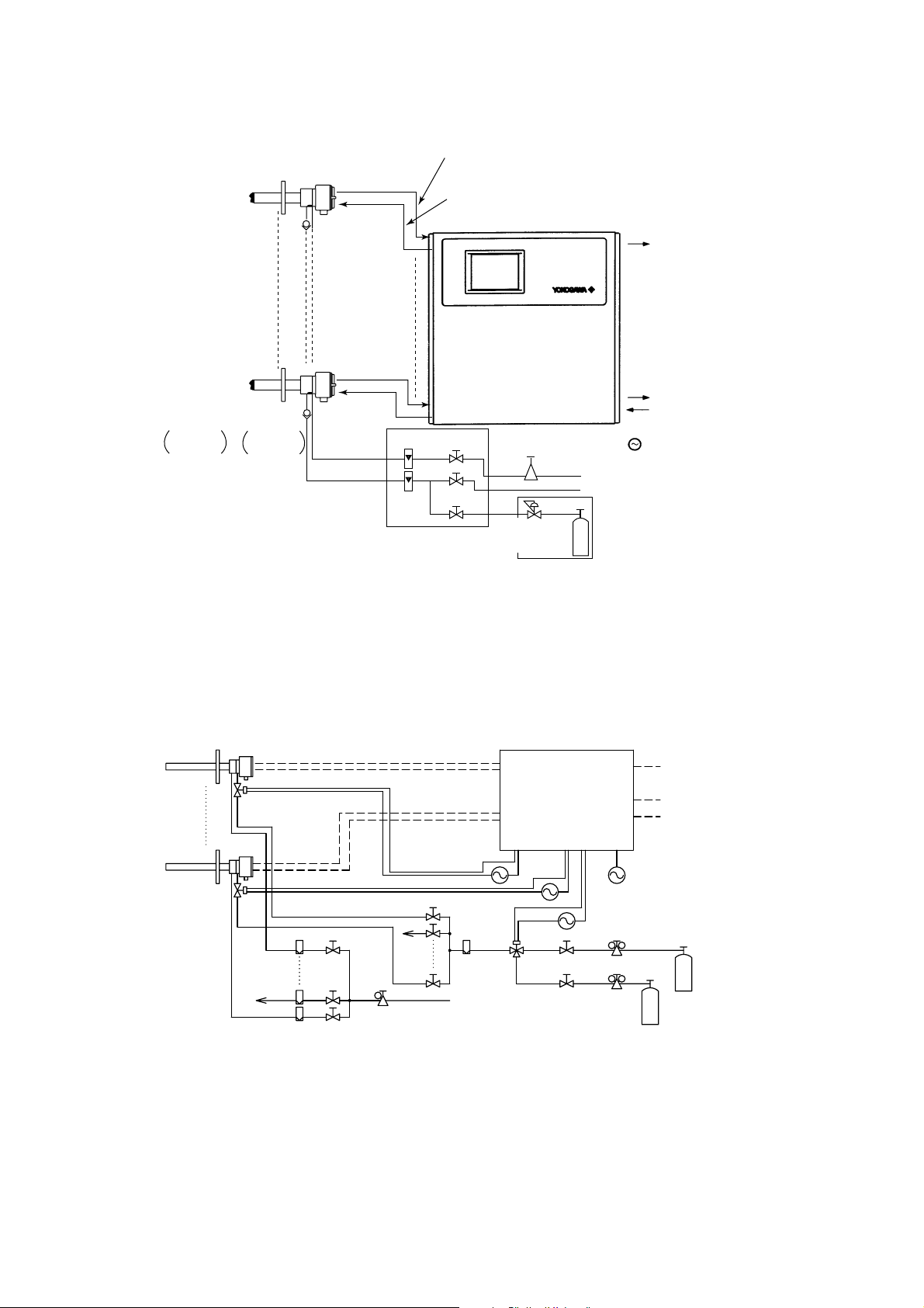
1.1.1 System Configuration Using Flow Setting Units for Manual Calibration
This system consists of detectors, an averaging converter, and flow setting units (Model
ZA8F), as shown in Figure 1.1. Note that the ZA8F Flow Setting Units are required as
many as the detectors connected to the averaging converter.
A reference gas needs to be supplied at a constant flow rate to the detectors. This
reference gas must be clean, dry air having a constant percentage of oxygen. Typically,
instrument air that has been dehumidified down to a dew point of approximately -208C
and is free from oil mist or dust, is used as the air source. This air is also used as a span
gas for the detectors during calibration. A zero gas for calibration is supplied from a
cylinder to the detectors.
IM 11M12D01-01E
1-1
Page 17
Stop
Valve
L9852CB
G7016XH
ZR22G Detector (max. 8 detectors)
Check
Valve
K9292DN
or
K9292DS
Reference gas
Calibration gas
Flowmeter
Model ZA8F
flow setting unit
Cell output, thermocouple output, cold contact compensation
2
(0.75mm
Heater
(1.25mm
, 6-core)
2
, 2-core)
Model AV550G Averaging Converter
Analog outputs :
Averaged and individual outputs
4 to 20 mA DC
Contact output
Contact input
Needle
Valve
Airset
Calibration gas
pressure regulator
Zero gas cylinder
Instrument air
Span gas (Calibration gas unit same as for zero gas)
Calibration gas unit case
Power supply :
100 / 115 V AC, 230V AC
50 / 60 Hz65%
F01.EPS
Figure 1.1 Typical System Configuration Using Flow Setting Units for Manual
Calibration
1.1.2 System Configuration to Perform Automatic Calibration
A typical system configuration to perform automatic calibration is illustrated in Figure
1.2. The system consists of detectors, an averaging converter, solenoid valves, needle
valves for flow control, and a float-type flowmeter.
Detector
Reference gas
line
Solenoid valve
Flowmeter
Signal
Heater
Calibration gas line
Needle valve
Needle valve
Instrument air
Air set
Averaging Converter (AV550G)
Calibration contact outputs
Solenoid valve
Flowmeter
Stop valve
Pressure regulator
Analog outputs:
Averaged and individual outputs
Contact output
Contact input
Power supply
Span gas cylinder
(Instrument air)
Zero gas cylinder
1-2
Figure 1.2 Typical System Configuration to Perform Automatic Calibration
IM 11M12D01-01E
Page 18
1.2 System Components
1.2.1 System Components and Their Applicability
1. Overview
Item
Averaging Converter
Detector
Flow setting unit
Needle valve
Flowmeter
Solenoid valve
Solenoid valve for
zero/span switching
Stop valve
Air set
Pressure regulator for
zero gas cylinder
Zero gas cylinder
AV550GSee §1.2.2
ZA8F
For flow control
0 to 1 L/min
G700
h
Solenoid valve for switching two streams
L9852CB, G7016XH
K9473XH, K9473XJ, G7004XF, K9473XG
G7013XF, G7014XF
G7001ZC
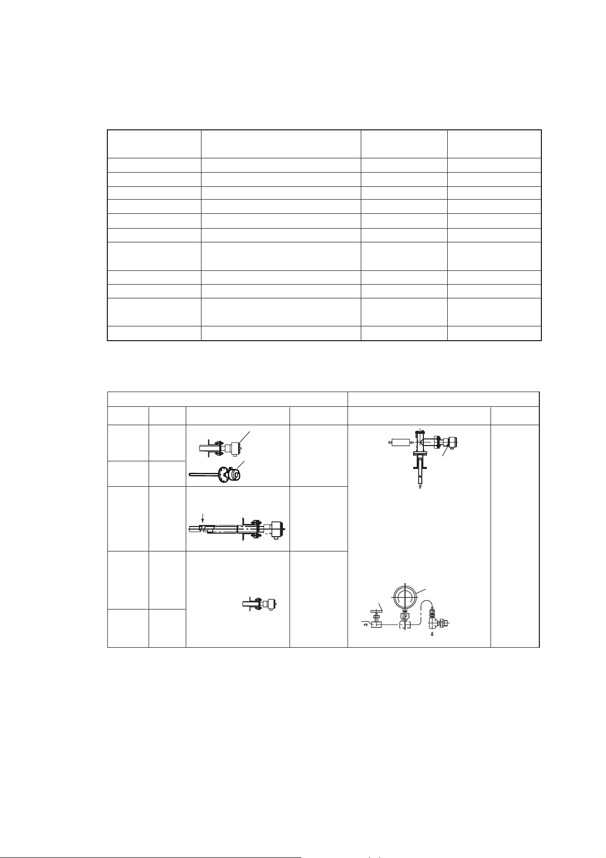
1.2.2 Detectors and Accessories
Process gas temperature 0 to 7008C Process gas temperature 0 to 14008C
Mounting
Horizontal
to
vertical
Vertical
Horizontal
to
vertical
Horizontal
to
vertical
Vertical
Insertion
length
0.4
to
2 m
2.5 m
or more
3 m
or less
0.4
to
2 m
2.5 m
or more
General-use Probe High temperature detector
Probe Protector
(ZO21R)
Gas Flow
Sample inlet
Filter
(K9471UA)
or
Dust Guard
Protector
(K9471UC)
Model / Part Number/
Specifications Manual Calibration
(A or B)
h
XP, E7057G
Detector
(ZO21DW-L)
Detector
(ZR22G)
+
Detector
(ZR22G)
Detector
(ZR22G)
h
Application
Boiler
Heating
furnace
For pulverized
coal boiler
with gas flow
velocity
10 m/s or more
Black liquid
recovery boiler
Cement
Kiln
Sample
outlet
Probe protector
for high
temperature use
ZO21P-H
Temperature:
Probe material SUS310S 8008C
Probe material SiC 14008C
Mounting: V ertical downwards
Insertion length: 1.0m, 1.5m
When duct pressure is atmospheric
or negative, attach air ejector.
High temperature auxiliary
ejector (E7046EC, E7046EN)
Needle
valve
Inlet
System 1
s
ssd
s
s
s
s
s
Absorption
structure
Sample inlet
Automatic Calibration
High
temperature
detector
Pressure gauge
Ejector
assy.
Blow
System 2
s
ssd
s
s
s
s
s
s
s
s
Tbl 1-2.eps
Application
Heating
furnace
F1.4E.EPS
IM 11M12D01-01E
1-3
Page 19

1-4
IM 11M12D01-01E
Page 20

2. Specifications
This chapter describes the specifications for the following:
ZR22G General-use separate-type detector (See Section 2.2.1)
ZO21R-L Probe protector (See Section 2.2.2)
ZR22G (0.15 m) High-temperature separate-type detector (See Section 2.3.1)
ZO21P-H Adapter for High temperature probe (See Section 2.3.2)
AV550G Averaging converter (See Section 2.4)
ZA8F Flow setting unit (See Section 2.5.1)
Other equipment (See Section 2.6)
2.1 General Specifications
2.1.1 Standard Specifications
2. Specifications
Measured Object: Oxygen concentration in combustion exhaust gas and mixed gas
(excluding inflammable gases)
To check if sampled gases containing a corrosive gas such as ammonia or
chlorine may be applicable to our oxygen gas analyzer, contact with
YOKOGAWA or its agent.
Measurement System: Zirconia system
Oxygen concentration: 0.01 to 100 vol% O
Output Signal: 4 to 20 mA DC (maximum load resistance 550V)
Measurement Range: Any setting in the range of 0 to 5 through 0 to 100 vol% O2 (in
1 vol% O2), or partial range
Digital Communication (HART): 250 to 550V, depending on number of field devices
connected to the loop (multi-drop mode).
Note: HART is a registered trademark of the HART Communication Foundation.
Display Range: 0 to 100 vol% O
Warm-up Time: Approx. 20 min.
Repeatability: (Excluding the case where the reference air is by natural convection)
60.5% Maximum value of range setting. (range up to 0 to 25 vol% O2)
2
2
IM 11M12D01-01E
61% Maximum value of range setting.
(range from 0 to 25 vol% O2 up to 0 to 100 vol% O2)
Linearity: (Excluding standard gas tolerance)
2-1
Page 21

(Excluding the case where the reference air flow is natural convection)
(Use oxygen of known concentration (in the measuring range) as the zero and
span calibration gas.)
61% Maximum value of range setting ; from 0 to 5 vol% O2 to 0 to 25
vol% O2 range
(Sample gas pressure: within 64.9 kPa)
63% Maximum value of range setting ; from 0 to 25 vol%O2 to 0 to 50 vol%
O2 range
(Sample gas pressure: within 60.49 kPa)
65% Maximum value of range setting ; from 0 to 50 vol% O2 to 0 to 100 vol%
O2 range (Sample gas pressure: within 60.49 kPa)
Drift: (Excluding the first two weeks in use)
(Excluding the case where the reference air flow is natural convection.)
Both zero and span 62% Maximum value of range setting/month
Response Time : Response of 90% within 5 seconds. (Measured from when gas is
introduced from calibration gas inlet and analog output start changing.)
2-2
IM 11M12D01-01E
Page 22

2.2 General-use Separate-type Detector and Related
Equipment
General-use separate-type detector ZR22G can be used in combination with the probe
protector ZO21R-L (see Section 2.2.2).
2.2.1 ZR22G General-use Separate-type Detector
Sample Gas Temperature: 0 to 7008C (Probe only)
It is necessary to mount the cell using Inconel cell-bolts when the temperature
is 6008C or greater.
700 to 14008C (with High Temperature Probe Adapter)
For high-temperature sample gas, apply 0.15 m length probe and High tempera
ture Probe Adapter ZO21P-H.
Sample Gas Pressure: -5 to +250 kPa (When the pressure in the furnace exceeds 3 kPa,
it is recommended that you compensate for this pressure. When the pressure in
the furnace exceeds 5 kPa, you must perform pressure compensation.)
For 0.15m probe, 0.5 to 5 kPa.
2. Specifications
No pressure fluctuation in the furnace should be allowed.
Note: When the detector is used in conjunction with a check valve and a ZA8F
Flow Setting Unit, the maximum pressure of sample gas is 150 kPa. When with
a check valve and a ZR40H Auto Calibration Unit, it is 200 kPa. If the pressure
of your sample gas exceeds these limits, consult with Yokogawa.
Probe Length: 0.15, 0.4, 0.7, 1.0, 1.5, 2.0, 2.5, 3.0, 3.6, 4.2, 4.8, 5.4 m
Probe Material: SUS 316 (JIS)
Ambient Temperature: -20 to +1508C
Reference Air System: Natural Convection, Instrument Air, Pressure Compensation
(other than for probe length 0.15 m)
Instrument Air System (excluding Natural Convection) :
Pressure; 200 kPa + the pressure inside the furnace (It is recommended to use
air which has been dehumidified by cooling to dew point -208C or less, and had
dust or oil mist removed.)
Consumption; Approx. 1 Nl/min
Material in Contact with Gas: SUS 316 (JIS), Zirconia, SUS 304 (JIS) (flange),
Hastelloy B, (Inconel 600, 601)
Construction: Heater and thermocouple replaceable construction.
Non explosion-proof JIS C0920 / equivalent to IP44D.
Equivalent to NEMA 4X/IP66 (Achieved when the cable entry is completely
sealed with a cable gland in the recirculation pressure compensated version.)
IM 11M12D01-01E
2-3
Page 23

Terminal Box Case: Material; Aluminium alloy
Terminal Box Paint Color:
Case; Off-white (Munsell 0.6GY3.1/2.0)
Cover; Moss green (Munsell 2.5Y8.4/1.2)
Finish: Polyurethane corrosion-resistant coating
Gas Connection: Rc1/4 or 1/4FNPT
Wiring Connection: G1/2, Pg13.5, M20 by 1.5 mm, 1/2 NPT
Installation: Flange mounting
Probe Mounting Angle: Horizontal to vertically downward.
When the probe insertion length is 2 m or less, can install at angles from
horizontal to vertically downward.
When the probe insertion length is 2.5 or more, mount vertically downward
(within 658), and if using a probe protector install at angles between horizontal
and vertically downward (within 658).
Weight:
Insertion length of 0.4 m: approx. 6 kg (JIS 5K 65) / approx. 11 kg (ANSI 150 4)
Insertion length of 1.0 m: approx. 8 kg (JIS 5K 65)) / approx. 13 kg (ANSI 150 4)
Insertion length of 1.5 m: approx. 10 kg (JIS 5K 65)) / approx. 15 kg (ANSI 150 4)
Insertion length of 2.0 m: approx. 12 kg (JIS 5K 65)) / approx. 17 kg (ANSI 150 4)
Insertion length of 3.0 m: approx. 15 kg (JIS 5K 65)) / approx. 20 kg (ANSI 150 4)
Insertion length of 3.6 m: approx. 17 kg (JIS 5K 65)) / approx. 22 kg (ANSI 150 4)
Insertion length of 4.2 m: approx. 19 kg (JIS 5K 65)) / approx. 24 kg (ANSI 150 4)
Insertion length of 4.8 m: approx. 21 kg (JIS 5K 65)) / approx. 26 kg (ANSI 150 4)
Insertion length of 5.4 m: approx. 23 kg (JIS 5K 65)) / approx. 28 kg (ANSI 150 4)
2-4
IM 11M12D01-01E
Page 24
d Model and Codes
n
Model
ZR22G
Length
-015
-040
-070
-100
-150
-200
-250
-300
-360
-420
-480
-540
Wetted material
-S
-C
Flange
(*3)
Reference air -C
Gas Thread -R
Connection box thread
Instruction manual
Options
Suffix code
-A
-B
-C
-E
-F
-G
-K
-L
-M
-P
-Q
-R
-S
-W
-E
-P
Valves
Filter
Tag plates
2. Specifications
Style: S2
Option
code
Separate type Zirconia Oxygen/ High Temperature Humidity Analyzer, Detector
0.15 m (for high temperature use) (*1)
0.4 m
0.7 m
1.0 m
1.5 m
2.0 m
2.5 m (*2)
3.0 m (*2)
3.6 m (*2)
4.2 m (*2)
4.8 m (*2)
5.4 m (*2)
SUS316
Stainless steel with Inconel calibration gas tube (*11)
ANSI Class 150 2 RF SUS304
ANSI Class 150 3 RF SUS304
ANSI Class 150 4 RF SUS304
DIN PN10 DN50 A SUS304
DIN PN10 DN80 A SUS304
DIN PN10 DN100 A SUS304
JIS 5K 65 FF SUS304
JIS 10K 65 FF SUS304
JIS 10K 80 FF SUS304
JIS 10K 100 FF SUS304
JIS 5K 32 FF SUS304 (for high temperature use) (*4)
JPI Class 150 4 RF SUS304
JPI Class 150 3 RF SUS304
Westinghouse
Natural convection
External connection (Instrument air) (*12)
Pressure compensated (*12)
Rc 1/4
-T
-P
-G
-M
-T
-Q
-J
-E
-A
1/4 FNPT
G1/2
Pg13.5
M20 x1.5 mm
1/2NPT
Quick connect (*9)
Japanese
English
Always -A
DERAKANE coating (*10)/D
Inconel bolt (*5)/C
/CV
/SV
/F1
/F2
/SCT
/PT
Check valve (*6)
Stop valve (*6)
Dust Filter (*7)
Dust Guard Protector (*7)
Stainless steel tag plate (*8)
Printed tag plate (*8)
Description
*1 Used with the ZO21P High Temperature Probe Adapter. Select flange (-Q).
*2 When installing horizontally the probe whose insertion length is 2.5 meters or more, use the Probe Protector. Be sure to specify
ZO21R-L-200-h. Specify the flange suffix code either -C or -K.
*3 The thickness of the flange depends on its dimensions.
*4 Not used in conjunction with —P (pressure compensation) for reference air. The flange thickness does not conform to JIS specificatio
*5 Inconel probe bolts and U shape pipe are used. Use this option for high temperature use (ranging from 600 to 700 8C).
*6 Specify either /CV or /SV option code.
*7 Not used with the high temperature humidity analyzer.
*8 Specify either /SCT or /PT option code.
*9 Not waterproof, avoid rain. Operating maximum temperature is 808C. Available only in the U.S.
*10 Available only in the U.S. DERAKANE is a registered trademark of the Dow Chemical Company.
*11 Recommended if measured gas contains corrosive gas like chlorine.
*12 Piping for reference air must be installed to supply reference air constantly at a specified flow rate.
IM 11M12D01-01E
T2.1.EPS
2-5
Page 25
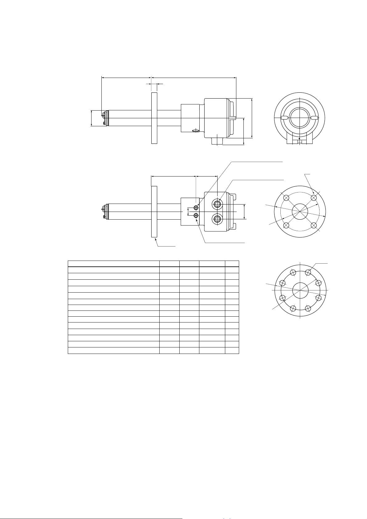
EXTERNAL DIMENSIONS
1. Model ZR22G Separate type Zirconia Oxygen Analyzer, Detectors
[50.8
L=0.15, 0.4, 0.7, 1.0,
1.5, 2.0, 2.5, 3.0
3.6, 4.2, 4.8, 5.4 (m)
L
t
Flange
283 to 292
155 to 163 69
25
Rc1/4 or 1/4NPT
Calibration gas inlet
[124
85
Rc1/4 or 1/4NPT
Reference air inlet
C
2-G1/2,2-1/2NPT etc.
Cable connection port
[A
48
[B
Flange
Flange
ANSI Class 150 2 RF SUS304
ANSI Class 150 3 RF SUS304
ANSI Class 150 4 RF SUS304
DIN PN10 DN50 A SUS304
DIN PN10 DN80 A SUS304
DIN PN10 DN100 A SUS304
JIS 5K 65 FF SUS304
JIS 10K 65 FF SUS304
JIS 10K 80 FF SUS304
JIS 10K 100 FF SUS304
JIS 5K 32 FF SUS304
JPI Class 150 4 RF SUS304
JPI Class 150 3 RF SUS304
Westinghouse
AB C
152.4
190.5
228.6
165
200
220
155
175
185
210
115
229
190
155
120.6
152.4
190.5
125
160
180
130
140
150
175
90
190.5
152.4
127
4 - [19
4 - [19
8 - [19
4 - [18
8 - [18
8 - [18
4 - [15
4 - [19
8 - [19
8 - [19
4 - [15
8 - [19
4 - [19
4 - [11.5
19
24
24
18
20
20
14
18
18
18
24
24
14
t
[A
[B
Flange
5
C
F2.1E.EPS
2-6
IM 11M12D01-01E
Page 26
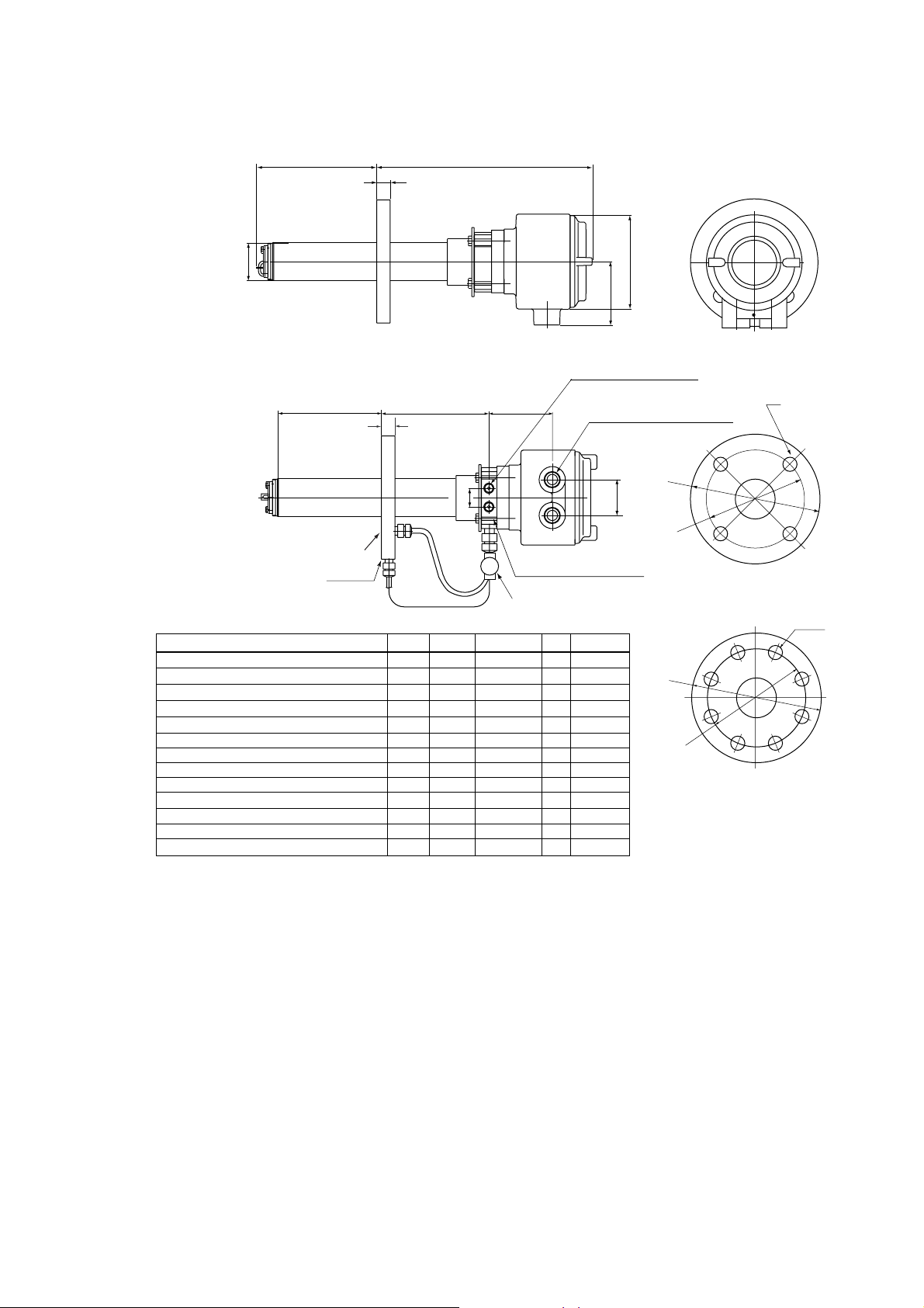
2. Specifications
Model ZR22G...-P (with pressure compensation) Separate type Zirconia Oxygen Analyzer, Detectors
L
[50.8
L=0.4, 0.7, 1.0, 1.5,
2.0, 2.5, 3.0, 3.6,
4.2, 4.8, 5.4 (m)
L
Reference gas outlet
Flange
ANSI Class 150 2 RF SUS304
ANSI Class 150 3 RF SUS304
ANSI Class 150 4 RF SUS304
DIN PN10 DN50 A SUS304
DIN PN10 DN80 A SUS304
DIN PN10 DN100 A SUS304
JIS 5K 65 FF SUS304
JIS 10K 65 FF SUS304
JIS 10K 80 FF SUS304
JIS 10K 100 FF SUS304
JPI Class 150 4 RF SUS304
JPI Class 150 3 RF SUS304
Westinghouse
Flange
t
303
156
t
25
PIPING
:B
PIPING : A
AB C
152.4
190.5
228.6
165
200
220
155
175
185
210
229
190
155
120.6
152.4
190.5
190.5
152.4
125
160
180
130
140
150
175
127
4 - [19
4 - [19
8 - [19
4 - [18
8 - [18
8 - [18
4 - [15
4 - [19
8 - [19
8 - [19
8 - [19
4 - [19
4 - [11.5
85
Rc1/4 or 1/4NPT
Reference air inlet
87
2-G1/2, 2-1/2NPT etc.
Cable connection port
48
Rc1/4 or 1/4NPT
Calibration gas inlet
Stop Valv e
t
PIPING
19
A
24
B
24
B
18
A
20
B
20
B
14
A
18
A
18
B
18
B
24
B
24
B
14
A
[124
C
[A
[B
Flange
C
[A
[B
Flange
F2.2E.EPS
IM 11M12D01-01E
2-7
Page 27
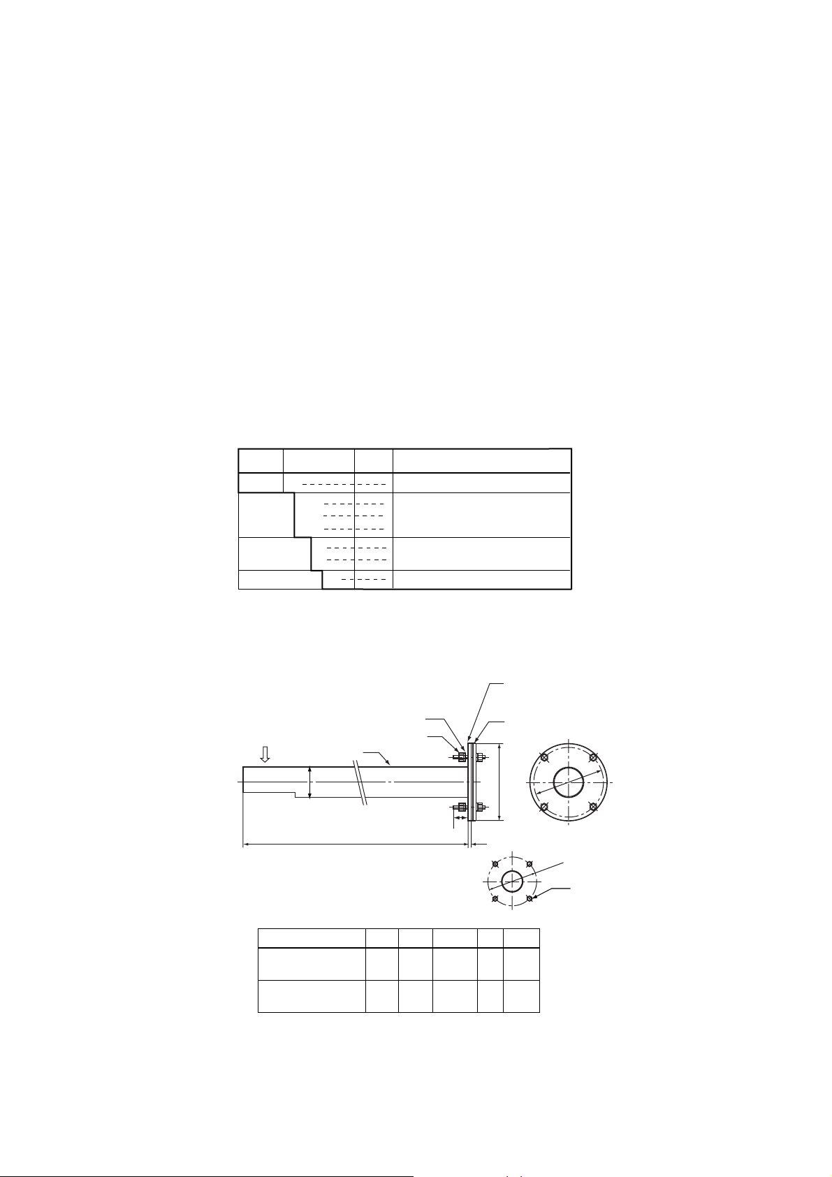
2.2.2 ZO21R-L Probe Protector
This probe protector is required for the general-use detector when it is used for oxygen
concentration measurements in powdered coal boilers or in fluidized furnaces to prevent
abrasion due to dust particles when gas flow exceeds 10 m/s.
When using a ZR22G general-use separate-type detector in the horizontal position, be
sure to select a probe protector ZO21R-L-hhh-h*B to support the probe.
Insertion Length: 1.05 m, 1.55 m, 2.05 m.
Flange: JIS 5K 65A FF SUS304. ANSI Class 150 4 FF (without serration). However,
flange thickness is different.
Material: SUS316 (JIS), SUS304 (JIS) (Flange)
Weight: 1.05 m; Approx. 6/10 kg (JIS/ANSI), 1.55 m; Approx. 9/13 kg (JIS/ANSI),
2.05 m; Approx. 12/16 kg (JIS/ANSI)
Installation: Bolts, nuts, and washers are provided for detector, probe adapter and
process-side flange.
Model Suffix code
ZO21R
Insertion
length
Flange ( *1)
*1 Thickness of flange depends on dimensions of flange.
Gas flow
-L
-100
-150
-200
-J
-A
Style code
[60.5
l (Insertion length)
l=1050,1550,2050
Option
code
*B
Washer (12)
Mounting nut (M12)
SUS316
Probe Protector (0 to 700 8C)
1.05 m (3.5 ft)
1.55 m (5.1 ft)
2.05 m (6.8 ft)
JIS 5K 65 FF SUS304
ANSI Class 150 4 FF SUS304
Style B
Description
D
t
T2.2E.EPS
Flange <1>
(with bolts, nuts,
gasket and washer)
gasket (t1.5)
[A
[B
[B
Unit ; mm
2-8
Flange<1>
JIS 5K 65 FF
SUS304
ANSI Class
150 4 FF SUS304
A
155
228.6
Dimensions of
holes on opposing surface
Ct
B
130
190.5
4 -[15
8 -[19
5
12
C
D
40
50
F2.3E.EPS
IM 11M12D01-01E
Page 28

2. Specifications
2.3 High-Temperature Separate-type Detector and Related
Equipment
2.3.1 ZR22G (0.15m) High-Temperature Separate-type Detector
Standard Specifications
Construction: Water-resistant, non-explosionproof
Probe length: 0.15 m
Terminal box: Aluminium alloy
Probe material: Probe material in contact with gas: SUS 316 (JIS) (Probe), SUS 304
(JIS) (Flange), Zirconia (Sensor), Hastelloy B, (Inconel 600, 601)
Weight: Approx. 3 kg
Installation: Flange mounting (The use of high-temperature detector probe adapter
ZO21P-H is necessary.)
Flange standard: JIS 5 K 32 FF equivalent (thickness varies)
Mounting angle: Any angle between horizontal and vertical (high-temperature probe is
fitted with an adapter) Reference gas and calibration gas piping
connection:Rc 1/4 or 1/4 NPT female
Cable inlet: G 1/2, Pg 13.5, M20 3 15, 1/2 NPT
Ambient temperature: -20 to 1508C
Sample gas temperature: 0 to 7008C (temperature at the measuring point of the sam-
pling gas. 0 to 7508C or 0 to 14008C when the probe adapter for high
temperature is used.
Temperature of the probe adapter shall not exceed 3008C to protect the
gasket and avoid the bolts seizing together.
Sample gas pressure: -0.5 to +5 kPa: when used at the range of more than 0 to
25 vol% O2, -0.5 to +0.5 kPa. (An auxiliary ejector is required for
negative pressure application.)
Model and Code
Refer to “Model and Code” in page 2-5.
External Dimensions
Refer to the Figure in page 2-6.
IM 11M12D01-01E
2-9
Page 29
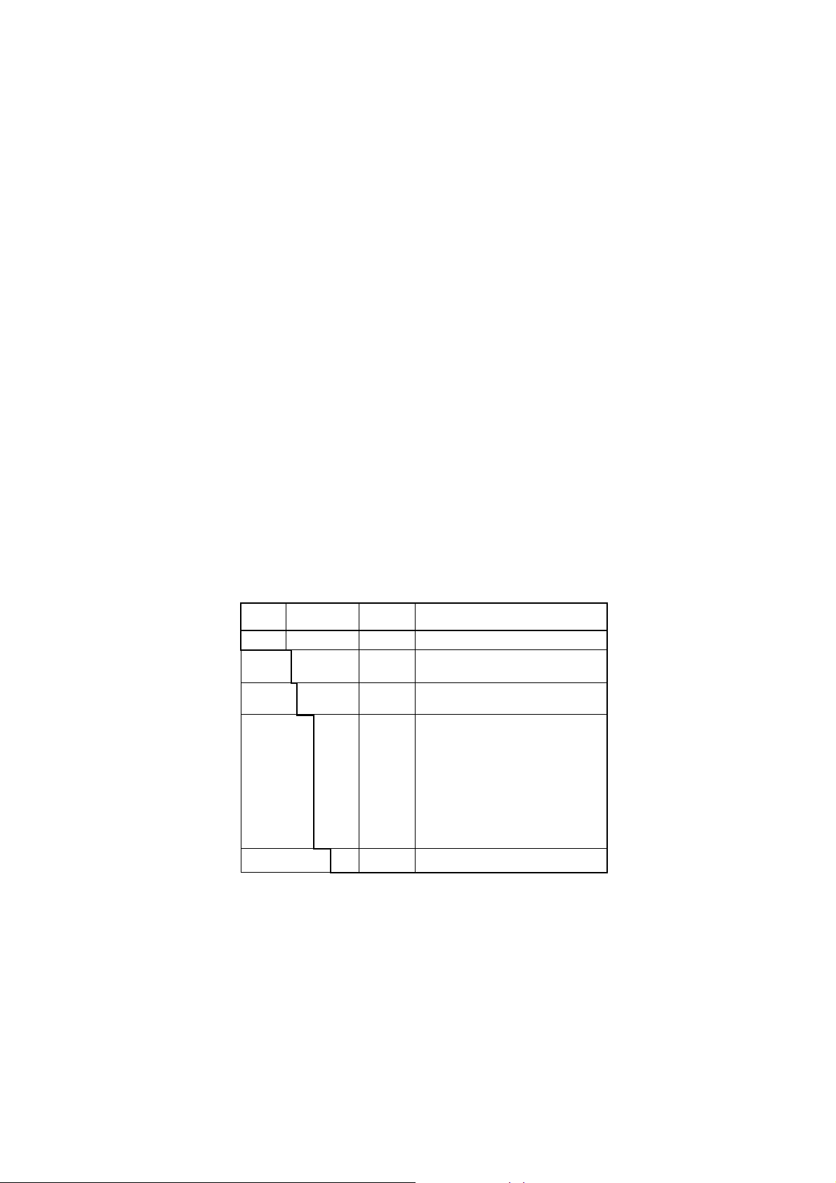
2.3.2 ZO21P-H Adapter for High-Temperature Probe
The probe adapter is used to lower the sample gas to a temperature below 7008C (below
3008C at probe adapter surface) before it is fed to the detector.
Insertion length: 1 m, 1.5 m
Material in Contact with Gas:
SUS 316 (JIS), Zirconia, SiC or SUS 310S, SUS 304(JIS) (flange)
Probe Material: SiC, SUS 310S (JIS)
Installation: Flange mounting (FF type or RF type)
Probe Mounting Angle: Vertically downward within 658
Where the probe material is SUS 310S, horizontal mounting is available.
Construction: Non explosion-proof. Rainproof construction
Weight:Insertion length of 1.0 m: approx. 6.5 kg (JIS) / approx. 8.5 kg (ANSI)
Insertion length of 1.5 m: approx. 7.5 kg (JIS) / approx. 9.5 kg (ANSI)
Sample gas temperature: 0 to 14008C (when using SiC probe) 0 to 8008C (when
using SUS 310S probe adapter)
Sample gas pressure: -0.5 to + 5 kPa. When using in the range of 0 to 25 vol% O2 or
more, the sample gas pressure should be in the range of -0.5 to +0.5 kPa.
(Where the sample gas pressure for the high-temperature probe is
negative, an auxiliary ejector is necessary.)
d Model and Codes
Model Suffix code
ZO21P
Material
Insertion
length
Flange
Style code
.......................................
-H
.....................................
-A
.....................................
-B
...............................
-100
...............................
-150
-J
-N
-M
-L
-A
-R
-Q
-T
-S
-E
Option
code
.............................
............................
............................
............................
............................
............................
............................
............................
............................
............................
......................
*A
Description
High Temperature Probe Adapter
SiC
SUS 310S
1.0 m
1.5 m
JIS 5K 50 FF SUS304
JIS 10K 65 FF SUS304
JIS 10K 80 FF SUS304
JIS 10K 100 FF SUS304
ANSI Class 150 4 RF SUS304
ANSI Class 150 2 1/2 RF SUS304
ANSI Class 150 3 RF SUS304
JPI Class 150 3 RF SUS304
JPI Class 150 4 RF SUS304
DIN PN10 DN50 A SUS304
Style A
T2.3E.EPS
2-10
IM 11M12D01-01E
Page 30

External Dimensions
Measured gas outlet
R1/2 (Note2)
Approx. 351
180
f60.5
2. Specifications
Unit: mm
Flange (Thickness)
JIS 5K 32 FF
Gasket (Thickness 3)
f60.5
170
Approx, 215
Approx. 48
Approx, 100
(Insertion length) (Note1)
f30
[A
[B
fA
f52 over
f115
Flange <1>
Flange provided
by customer
High temperature
Probe SiC pipe
C
110
f124
85
Detector (ZR22G)
69
Reference air inlet <2>
25
Pipe hole (2-G1/2,2-1/2NPT.etc)
Calibration gas inlet <3>
(Note 1) 1=1000 or 1500 (mm)
(Note 2) Sample gas outlet
(if the sample gas pressure is negative,
connect the auxiliary ejector.)
42
IM 11M12D01-01E
<1> Flange
JIS 5K 50 FF SUS304 130
ANSI Class 150 4 RF SUS304
<2>,<3> joint
Rc 1/4
1/4 FNPT
228.6
AB
105
190.5
C
4-[15
8-[19
F2.4E.EPS
2-11
Page 31

2.4 AV550G Averaging Converter
2.4.1 Standard Specification
Compatibility of Detectors : ZR22G, ZO21D, ZO21DW
Number of Detectors : 1 to 8
Expandable up to 8
Bases, these for 4CH and 8CH are available
Averaging interval : 0.2 seconds
Display: 5.7 inches color LCD display of size 320 by 240 dot with touch screen
Output Signal: 4 to 20 mA DC (maximum load resistance 550V)
Average-value Output; 3 points
Independent Output; Output to each channel
Common isolation / Individual isolation selectable
(Note) Number of averaging output is 2 when suffix code “ -F”
(FOUNDATION Fieldbus communication) is selected.
Independent Output; Output to each channel
Common isolation / Individual isolation selectable.
Used exclusively for communication when suffix code “ -F”
(FOUNDATION Fieldbus communication) is selected.
Contact Output: Contact capacity 30V DC 3A, 250V AC 3A (resistive load)
Normally open / normally closed selectable
Common Contact Output; 5 points, Four of the output points can be selected to either
normally energized or normally deenergized status.
Contact output 5 is normally energized.
Contact Output for Individual Channel Fail; Output to each channel
Solenoid Valve Contact Output: Contact capacity 30V DC 1A, 250V AC 1A,
24V DC (option code "/24" ) maximum output current 50 mA
Contact Input: 2 points, voltage free contacts
Ambient Temperature: -5 to +508C
Storage Temperature: -20 to +708C
Humidity Range: 10 to 85%RH (non-condensing)
Installation Altitude: 2000 m or less
Category based on IEC 1010: II (Note)
Pollution degree based on IEC 1010:2 (Note)
Note: Installation category, called over-voltage category, specifies impulse withstand
voltage. Category II is for electrical equipment.
Pollution degree indicates the degree of existence of solid, liquid, gas or other
inclusions which may reduce dielectric strength. Degree 2 is the normal indoor
environment.
Power Supply Voltage: Ratings; 100 / 115 V AC, 230 V AC
Acceptable range; 85 to 126.5 V AC, 195.5 to 253 V AC
Power Supply Frequency: Rating; 50/60 Hz
Acceptable range; 50Hz±5%, 60Hz±5%
Power Consumption:
Max 1 kw for steady operation
Max 1.8 kw for warm-up
Normally energized.
2-12
IM 11M12D01-01E
Page 32

2. Specifications
Safety and EMC conforming standards
Safety: Conforms to EN 61010-1: 2001
CSA C22.2 No.1010.1 certified
UL 61010B-1 certified
EMC: Conforms to EN 61326: 2002
AS/NZS CISPR II
Maximum Distance between Probe and Converter:
Conductor two-way resistance must be 10V or less (when a 1.25mm2 cable or equivalent
is used, 300 m or less)
Construction: Indoor installation
Wiring Connection: Number of wire holes 30 pieces
Wire hole size: [17 mm for grommet
[6 to [12 mm for cable gland (option).
Installation: Wall mounting
Case: Aluminum alloy (100 V type)
Paint Color: Silver Gray (Munsell 3.2PB7.4/1.2)
2.4.2 Functions
Finish: Polyurethane corrosion-resistance coating
Weight: Approx. 13kg (100 V type)
Display Functions:
Value Display; Displays values of the measured oxygen concentration, etc
Graph Display; Displays trends of measured oxygen concentration
Data Display; Displays various useful data for maintenance, such as cell
temperature, reference junction temperature, maximum/minimum
oxygen concentration, or the like.
Status Message; Indicates an alarm or error occurrence with flashing of the
corresponding icon. Indicates status such as warming-up,
calibrating, or the like by icon.
Alarm, Error Display; Displays alarms such as “Abnormal cell e.m.f.” when any
such status occurs.
Calibration functions:
Auto-Calibration; It calibrates automatically at specified intervals.
Semi-auto Calibration; Input calibration direction on the touch screen or contact,
then it calibrates automatically afterwards.
IM 11M12D01-01E
Manual Calibration; Calibration with opening/closing the valve of calibration
gas in operation interactively with an LCD touch screen.
Validation Function: Permits control room activation of zero, span or midpoint gas
concentrations without running an actual calibration.
Blowback Function:
Output through the contact in the set period and time. Auto/semi-auto
selectable.
2-13
Page 33

Maintenance Functions:
Setup Functions:
Self-diagnosis:
Password Functions:
Display and Setting Content:
Measuring Related Items:
Display Items:
Can operate updated data settings in daily operation and checking. Display data
settings, calibration data settings, blowback data settings, current output loop
check, input/output contact check.
Initial settings suit for the plant conditions when installing the converter.
Equipment settings, current output data settings, alarm data settings, contact data
settings, other settings.
This function diagnoses conditions of the converter or the probe and indicates
when any abnormal condition occurs.
Enter your password to operate the analyzer excepting data display. Individual
passwords can be set for maintenance and setup
Oxygen concentration (vol% O2)
Cell e.m.f(mV), thermocouple e.m.f(mV), cold junction resistance(V), cell
temperature(8C), cold junction temperature(8C), span correction factor(%), zero
correction factor(%), cell response time(second), cell condition(in four grades),
cell internal resistance(V), next calibration estimate(year/month/day), heater ontime rate(%), time(year/month/day, hour/minute), software revision, maximum/
minimum/average oxygen concentration(vol%O2), calibration record(ten times),
internal temperature rise alarm record.
Calibration Setting Items:
Span gas concentration(vol%O2), zero-gas concentration(vol%O2), calibration
mode(auto, semi-auto, manual), calibration type and method(zero-span calibra
tion, zero calibration only, span calibration only), stabilization time(minute/
second), calibration time(minute/second), calibration period(day/hour), starting
time(year/month/day, hour/minute)
Equipment Related Items:
Measuring gas selection; wet/dry
Detector selection; ZR22/ZO21
Output Related Items:
Analog output/output mode selection, output conditions when warming- up/
maintenance/calibrating (during blowback)/abnormal, 4 mA/20 mA point
oxygen concentration (vol%O2), time constant, preset values when warming-up/
maintenance/calibrating during blowback abnormal, output preset values on
abnormal.
Alarm Related Items:
Oxygen concentration high-alarm/high-high alarm limit values(vol% O2),
oxygen concentration low-alarm/low-low alarm limit values (vol% O2), oxygen
concentration alarm hysteresis (vol% O2), oxygen concentration alarm
detection, alarm delay (seconds)
Converter Output: mA analog output (4 to 20mA DC (maximum load resistance of
550V)).
2-14
Average-value output; 3 points (average value a, average value b, average
a + b
c =
)
2
IM 11M12D01-01E
Page 34

2. Specifications
Independent Output; Output to each channel
Range; any setting between 0 to 5 through 0 to 100 vol% O2 in 1 vol% O2, or
partial range is available (Maximum range value/minimum range value
1.3 or more)
For the log output, the minimum range value is fixed at 0.1 vol% O2.
4 to 20 mA DC linear or log can be selected.
Input/output isolation.
Output damping: 0 to 255 seconds.
Hold/non-hold selection, preset value setting possible with hold
Contact Output: Five points, contact capacity 30 V DC 3 A, 250 V AC 3 A (resistive
load)
Four of the output points can be selected to either normally energized or
normally deenergized status.
Delayed functions (0 to 255 seconds) and hysteresis function (0 to 9.9 vol%O2
can be added to high/low alarms.
The following functions are programmable for contact outputs.
(1) Abnormal, (2) High-high alarm, (3) High alarm, (4) Low-low alarm, (5)
Low-alarm, (6) Maintenance, (7) Calibration, (8) Range switching answerback, (9) Warm-up, (10) Calibration-gas pressure decrease (answerback of
contact input), (11) Blowback start, (12) Process alarm (answerback of contact
input), (13) Calibration coefficient alarm, (14) Internal temperature rise alarm.
Contact output 5 is set to normally operated, fixed error status.
Contact Output for Individual Channel Fail: Output to each channel
Normally energized.
Each channel cards provides a failure contact output.
(1)Abnormal cell, (2)abnormal cell temperature(high/low), (3)abnormal channel
card, (4)abnormal control card, (5)abnormal card commu nication
Contact Input: Two points, contact input
The following functions are programmable for contact inputs:
(1) Calibration-gas pressure decrease alarm, (2) Range switching, (3) External
calibration start, (4) Process alarm (if this signal is received, the heater power
turns off), (5) Validation start, (6) Blow-back start
Self-diagnosis: Abnormal cell, abnormal cell temperature(high/low), abnormal channel
card, abnormal control card, abnormal card communication
Calibration: Method; zero/span calibration
Calibration mode; automatic, semi-automatic and manual (All are operated
interactively with an LCD touchscreen). Either zero or span can be skipped.
Zero calibration-gas concentration setting range; 0.3 to 100 vol% O2 (0.01 vol%O2
in smallest units). Span calibration-gas concentration setting range: 4.5 to 100
vol% O2 (0.01 vol% O2 in smallest units). Use nitrogen-balanced mixed gas
containing 0 to 10 % scale of oxygen, and 80 to 100 % scale of oxygen for
standard zero gas and standard span-gas respectively.
IM 11M12D01-01E
Calibration period; date/time setting; maximum 255 days/23hours.
2-15
Page 35

FOUNDATION Fieldbus communication function
The bi-directional digital communication as standard for FOUNDATION Fieldbus that is
established by Fieldbus foundation.
Interface : FOUNDATION Fieldbus H1 (communication speed : 31.25 kb/s)
Physical layer type :
113 (standard-power signaling, bus powered, non I.S.)
Communication line condition:
power supply----9 to 32 VDC, current supply----15 mA (Max)
Signal insulation :
communication terminal to grand terminal, dielectric strength 500 Vrms
(50/60 Hz, 1 min).
Device : Link master
Function block :
AI block :
3 blocks (1 block for each channels)
Transfer the data of averaging oxygen concentration to other instruments.
DI block :
2 blocks
Transfer the status of error and alarm to other instruments.
MAI block
1 block (8 channels)
Transfer the data of oxygen concentration to other instruments.
MAO block
1 block (8 channels)
Import the data of other instruments.
2-16
IM 11M12D01-01E
Page 36

d Model and Suffix Code
2. Specifications
1. Detector
Refer to GS 11M12A01-01E for a detailed explanation of the detector specifications
and available accessories.
2. Averaging Converter
Model
Suffix Code
AV550G
Base
Number of Channel
Card (*2)
Display
Power supply
-B
-A1
-A2
-A3
-A4
-A5
-A6
-A7
-A8
-B1
-B2
-B3
-B4
-B5
-B6
-B7
-B8
-J
-E
-F
-G
-1
-2
-A
(*1)
Communication
Options
Select code "-B" (8 Channel Base) when future expansion exceeding 4 channels is expected.
(*1)
By so doing, the expansion can be made economically.
(*2)
Common isolation is recommended, when the same instrument receives the analog
outputs from each channel card. Individual isolation is recommended to prevent the
trouble by mutual interference, when different instrument receives the analog outputs
from each channel card.
(*3)
When suffix code "-2" (230 V AC) is selected, select code "-A" (4 Channel Base).
(*4)
When suffix code "-F" (FOUNDATION Fieldbus communication) is selected, used exclusively
for communication.
(*5)
Input 01 to 30 in h h.
Option
Code
Specification
Averaging Converter
4 Channel Base
8 Channel Base
Oxygen Channel Card, Common Isolation
1
2
Oxygen Channel Cards, Common Isolation
3
Oxygen Channel Cards, Common Isolation
4
Oxygen Channel Cards, Common Isolation
5
Oxygen Channel Cards, Common Isolation
6
Oxygen Channel Cards, Common Isolation
7
Oxygen Channel Cards, Common Isolation
8
Oxygen Channel Cards, Common Isolation
1
Oxygen Channel Card, Individual Isolation
2
Oxygen Channel Cards, Individual Isolation
3
Oxygen Channel Cards, Individual Isolation
4
Oxygen Channel Cards, Individual Isolation
5
Oxygen Channel Cards, Individual Isolation
6
Oxygen Channel Cards, Individual Isolation
7
Oxygen Channel Cards, Individual Isolation
8
Oxygen Channel Cards, Individual Isolation
Japanese
English
French
German
100 / 115 V AC
230 V AC
-E
-F
/SCT
/24
/G
HART communication
FOUNDATION Fieldbus communication
Stainless steel tag plate
24 Voltage output for Solenoid valve
Cable gland (Numbers in )
(*3)
(*5)
(*4)
T02.EPS
IM 11M12D01-01E
3. Channel Code
Model
Suffix Code
AV55CM
-A1
-A2
-A3
-A4
-A5
-A6
-A7
Number of
Channels (*1)
-A8
-B1
-B2
-B3
-B4
-B5
-B6
-B7
-B8
-A
Option
(*1) -A h are common Isolation types -B h are Individual Isolation types
Up to 4 channel cards can be added in the 230 VAC version.
(*2) Expansion power supply unit is required, when using the 4 channel base and extending the number of
channel cards to five or more.
The expansion power supply unit cannot be added in the 230 VAC version.
(*3) Expansion power supply unit is required, when using the 4 channel base and extending the number of
channel cards to five or more. Available only in U.S.
Option
/K1
/K2
Code
Specification
Channel Card
Oxygen Channel Card, Common Isolation
1
2
Oxygen Channel Cards, Common Isolation
3
Oxygen Channel Cards, Common Isolation
4
Oxygen Channel Cards, Common Isolation
5
Oxygen Channel Cards, Common Isolation
6
Oxygen Channel Cards, Common Isolation
7
Oxygen Channel Cards, Common Isolation
8
Oxygen Channel Cards, Common Isolation
1
Oxygen Channel Card, Individual Isolation
2
Oxygen Channel Cards, Individual Isolation
3
Oxygen Channel Cards, Individual Isolation
4
Oxygen Channel Cards, Individual Isolation
5
Oxygen Channel Cards, Individual Isolation
6
Oxygen Channel Cards, Individual Isolation
7
Oxygen Channel Cards, Individual Isolation
8
Oxygen Channel Cards, Individual Isolation
Always -A
Expansion power supply unit for dry contact
output of solenoid valve output.
Expansion power supply unit for 24 volt
output of solenoid valve output.
(*2)
(*3)
T03.EPS
2-17
Page 37

• External Dimensions
165.1 266.735.5
Extension view
7
6
150 30017.3
480
465
3.5
R
3.5
R
R3.5
R
3
457
Distance between mounting hole
465
R
3
(without cable gland and grommet)
480
4-knobs
Unit: mm
166.5
10-M5
holes
165.1 266.7
150 300
Maintenance space
200
• AV550G Standard Accessories
Name
Fuse 2 2.5A
Hexagonal
Allen Wrench
Part No
A1112EF
L9827AS 1 For lock screw.
200
300
200
RemarksQuantity
T01.EPS
800
2-18
IM 11M12D01-01E
Page 38

2.5 ZA8F Flow Setting Unit
2.5.1 ZA8F Flow Setting Unit
This flow setting unit is applied to the reference gas and the calibration gas in a system
configuration (System 1).
This unit consists of a flow meter and flow control valves to control the flow of calibration gas and reference air.
Standard Specifications
FIowmeter: Calibration gas; 0.1 to 1.0 l/min. Reference air; 0.1 to 1.0 l/min.
Construction: Dust-proof and rainproof construction
Case Material: SPCC (Cold rolled steel sheet)
Painting: Baked epoxy resin, Dark-green (Munsell 2.0 GY 3.1/0.5 or equivalent)
Pipe Connections: Rc1/4 or 1/4FNPT
Reference Air pressure: Clean air supply of measured gas pressure approx. 50 kPa G
(or measured gas pressure plus approx. 150 kPa G when a check valve is used)
2. Specifications
pressure at inlet of the auto-calibration unit.(Maximum 300 kPaG)
Air Consumption: Approx. 1.5 l/min
Weight: Approx. 2.3kg
Calibration gas (zero gas, span gas) flow 0.7 l/m (at calibration time only)
Note
Use instrument air for span calibration gas, if no instrument air is available, contact
YOKOGAWA.
Model Suffix code Option code Description
ZA8F
Joint
Style code *B
-J
-A
Flow setting unit
Rc 1/4
With 1/4" NPT adapter
Style B
T2.5E.EPS
IM 11M12D01-01E
2-19
Page 39
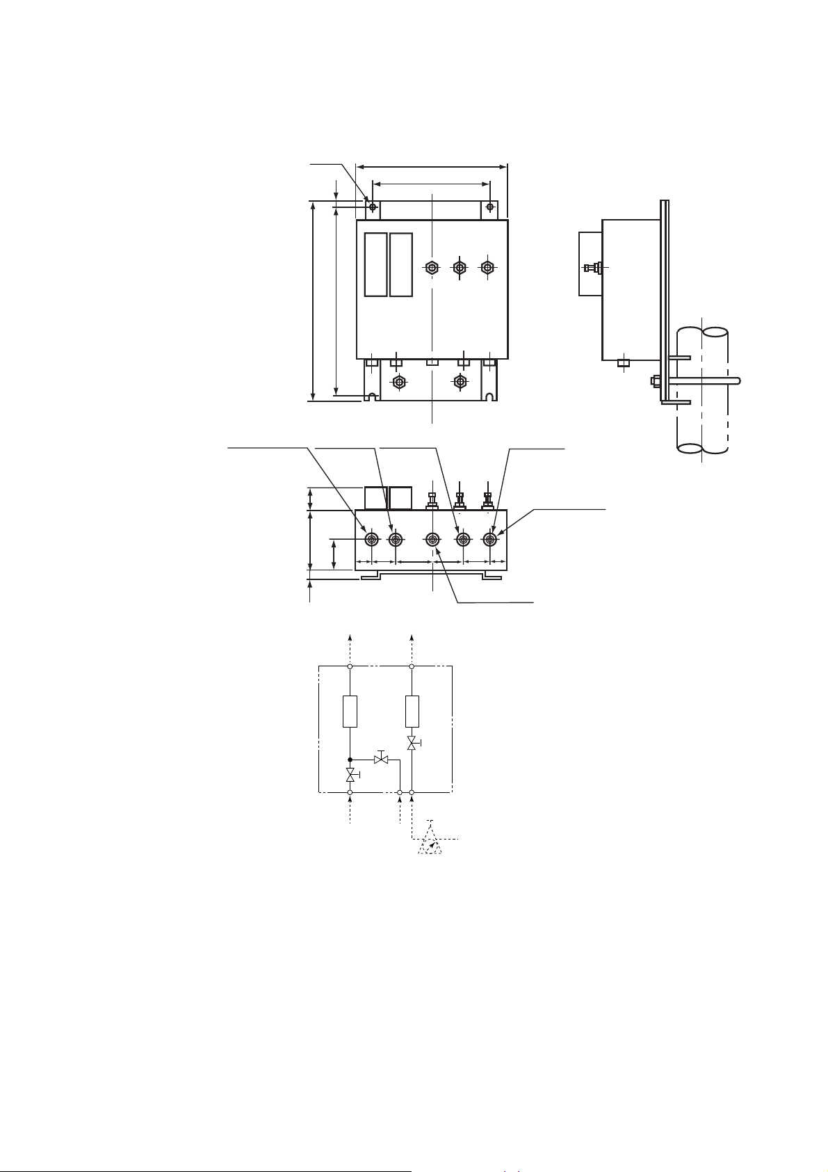
• External Dimensions
f6 hole
7
Unit: mm
180
140
REFERENCE CHECK
Reference air outlet
235.8
222.8
Zero gas outlet
268
70
35
REFERENCE
SRAN
Span gas inlet
20 2035 35
CHECK
OUT
35
REF
OUT
35
ZERO
Zero gas inlet
Instrument air inlet
4-Rc1/4
Piping connection
port
2-20
ZERO
GAS IN
Flow
meter
SPAN
GAS IN
Flow
meter
AIR IN
Instrument air
Approx 1.5 l/min.
Air pressure ;
Airset
without check valve ; measured gas pressure 1 approx.50 kPaG
with check valve ; measured gas pressure 1 approx.150 kPaG
F2.6E.EPS
IM 11M12D01-01E
Page 40
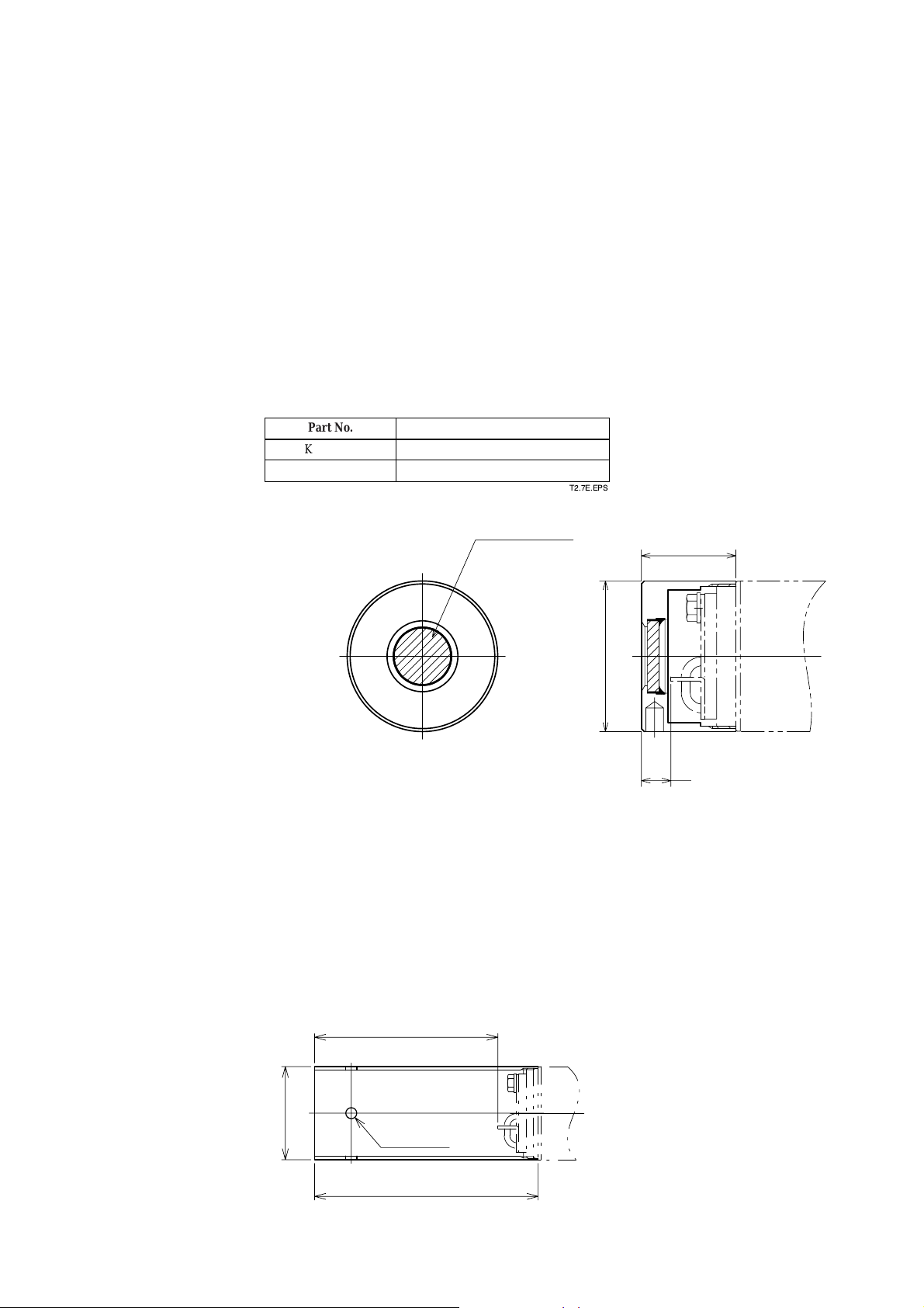
2.6 Other Equipment
f51
32
10
SiC Caborundum filter
Increasing of insertion length
F2.8E.EPS
Unit : mm
2.6.1 Dust Filter for the Detector (Part No.: K9471UA)
This filter is used to protect the detector sensor from a corrosive dust component or from
a high concentration of dust when the oxygen concentration in utility boilers or concrete
kilns are to be measured.
This filter requires a measurement gas flow of 1m/sec or faster, for circulation of the gas
in the sensing part.
• Standard specification
Applicable detector: Standard-type detector for general-use (the measurement gas
flow should be approximately perpendicular to the probe.)
Mesh: 30 microns
Material: Sic (Filter), SUS316 (JIS)
Weight: Approx. 0.2 kg
2. Specifications
Part No.
K9471UA
K9471UX
Description
Filter
Tool
2.6.2 Dust Guard Protector (Part No.: K9471UC)
Recommended to be used when sample gas is likely to flow directly into the cell due to
its flow direction in the stack or the like, flammable dust may go into the cell, or water
drops are likely to fall and remain in the cell during downtime or the like due to the
installation position.
Material: SUS316
Weight: Approx. 0.3 kg
T2.7E.EPS
IM 11M12D01-01E
Increasing of insertion length
100
50.8
[
4-[6
122
F11-1.eps
2-21
Page 41

2.6.3 Auxiliary Ejector for High Temperature (Part No. E7046EC or E7046EN)
This ejector is used where pressure of measured gas for high temperature detector is
negative. This ejector consists of an ejector assembly, a pressure gauge and a needle
valve.
Standard Specifications
Ejector Assembly
Ejector Inlet Air Pressure: 29 to 68 kPa G
Air Consumption: Approx. 30 to 40 l/min
Suction gas flow rate: 3 to 7 l/min
Connection to high-temperature probe adapter: R 1/2
Connection: Rc1/4 or 1/4 FNPT, SUS304 (JIS)
Tube Connection: ([6/[4 mm or 1/4 inch copper tube or stainless tube)
Pressure Gauge Assembly
Type: JIS B7505, A1.5U3/8 x75
Material in Contact with Gas: SUS316 (JIS)
Case Material: Aluminum alloy (Paint color; black)
Scale: 0 to 100 kPa G
Bushing (G3/8 x Rc1/4 or 1/4NPT, SUS304 (JIS))
Needle Valve
Connection: Rc1/4 or 1/4FNPT
Material: SUS316 (JIS)
Part No.
E7046EC
E7046EN
Description
RC 1/4 [6 / [4 TUBE joint: SUS304 (JIS)
1/4 NPT, 1/4 TUBE joint: SUS304 (JIS)
T2.8E.EPS
2-22
IM 11M12D01-01E
Page 42

E7046EC ; Piping connections, Rc1/4( p part) or Rc1/4( pp part ),
E7046EN ; Piping connections,1/4NPT female ( p part) or 1/4NTP male( pp part )
Pressure gauge
39
f63f4 or 1/4 inch, conduit (stainless)
2. Specifications
Needle
valve
lnstrument
air inlet
Po (kPa)
200
100
f43
Height when
fully open
Approx.67
p
40
Not included in high
temperature use
auxiliary ejector.
1)
P= 0.5
p
Approx.88
Qa (l/min)
40
30
Needle
valve
Air
source
Ejector assembly
Approx.
pp
2)
70
38
p
20
Auxiliary ejector for
high-temperature
mounting place use.
Po
PT 1/2 male
Pressure gauge
Qa
L
Detector
Ejector
Pg
Qg
0
5
L (m)
Pg (kPa)
-1.0
-0.5
0
40
P (kPa)
Suction pressure characteristics
IM 11M12D01-01E
15
10
3)
80
60
0
40
P (kPa)
Air consumption characteristicsPressure setting characteristics
Qg (l/min)
Gas Pressure:
8
0 kPa
4
Gas pressure : -15 Pa
0
40
P (kPa)
Suction flow characteristics
4)
60
60
80
80
(Note) Pipes and connectors are not provided.
Gas
Po (kPa) : Pressure setting
P (kPa) : Drive pressure (at the ejector entrance)
Pg (kPa) : Suction pressure
Qa (l/min) : Air consumption
Qg (l/min) : Suction flow
L (m) : Distance between the ejector and the pressure
gauge
F2.9E.EPS
2-23
Page 43

< Pressure setting for the auxiliary ejector for high-temperature use >
Pressure supply for the auxiliary ejector should be set so that the suction flow of the
measured gas becomes approximately 5 l/min.
To set this, proceed as follows:
(1) In Graph 4, draw a horizontal line from the 5 l/min point. on the vertical axis
(Suction flow: Qg) toward the gas pressure line to be used, to find the point of
intersection.
Draw a line vertically down from the point of intersection to the axis to find the
drive pressure, P (at the ejector entrance).
(2) In Graph 1, determine Po (pressure setting) from L (the distance between the ejector
and the pressure gauge).
(3) Open the needle valve to supply air for the ejector to the pressure gauge until it
indicates the pressure setting, Po.
Note
Qg (the suction flow) may require change according to the conditions of use. Refer to
Section 3.2.2 and Section 4.1.4 for details.
Graph explanation
1) Graph 1 is to compensate for pressure loss in piping between the ejector and the
pressure gauge, and find Po (pressure setting).
2) Graph 2 shows correlation between P (drive pressure) and Qa (air consumption).
3) Graph 3 shows correlation between P (drive pressure) and Pg (suction pressure; when
the measured gas inlet of the ejector is closed).
4) Graph 4 shows correlation between P (drive pressure) and Qg (suction flow) for each
gas pressure.
2.6.4 Stop Valve (Part No. L9852CB or G7016XH)
This valve is mounted on the calibration gas line in the system using flow setting unit
for manual calibration.
Standard Specifications
Connection: Rc 1/4 or 1/4 FNPT
Material: SUS 316 (JIS)
Weight: Approx. 80 g
Part No.
L9852CB
G7016XH
Rc1/4 or 1/4NPT
Joint: RC 1/4, Material: SUS 316 (JIS)
Joint:
43
40
Description
1/4 NPT,
Material:
55
(Full open length)
F15.EPS
SUS316
(JIS)
T2.9E.EPS
2-24
IM 11M12D01-01E
Page 44
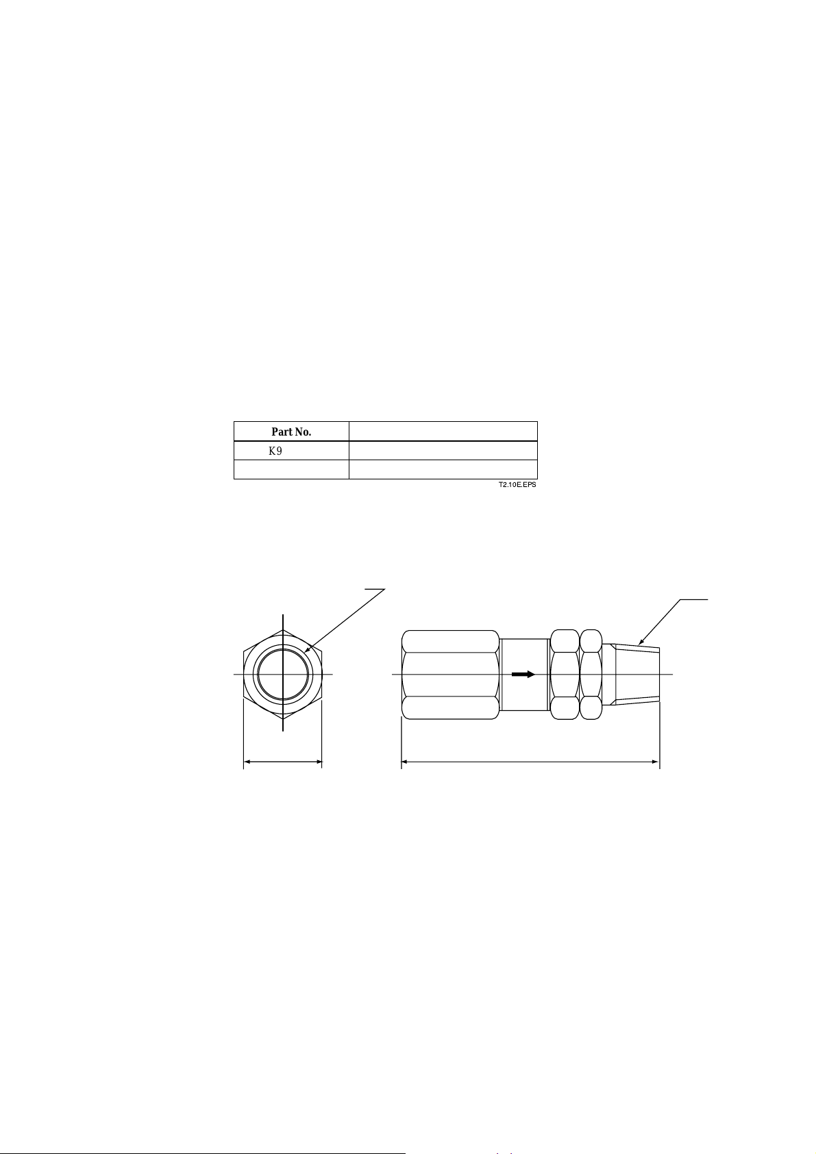
2.6.5 Check Valve (Part No. K9292DN or K9292DS)
This valve is mounted on the calibration gas line in the system such as the one using
flow setting units for manual calibration or the one performing when unburnt gas is
generated.
This valve prevents the process gas from entering the calibration gas line. Although it
functions as a stop valve, operation is easier than a stop valve as it does not require
opening/closing at each calibration.
Screw a check valve, instead of a stop valve into the calibration gas inlet of the detector.
Standard Specifications
Connection: Rc1/4 or 1/4FNPT
Material: SUS304 (JIS)
Pressure: 70 kPa G or more and 350 kPa G or less
Weight: Approx. 40 g
2. Specifications
1/4 NPT
A
Description
, Material:
SUS304
Part No.
K9292DN
K9292DS
K9292DN : Rc 1/4 (A part), R 1/4(B part)
K9292DS : 1/4FNPT (A part),1/4NPT(Male)(B part)
Approx.19
Joint: RC 1/4, Material: SUS304 (JIS)
Joint:
(JIS)
T2.10E.EPS
Unit : mm
B
Approx.54
F2.11E.EPS
IM 11M12D01-01E
2-25
Page 45

2.6.6 Air Set
This set is used to lower the pressure when instrument air is used as the reference and
span gases.
• Part No.K9473XH or K9473XJ
Standard Specifications
Primary Pressure: Max. 2 MPa G
Secondary Pressure: 9.8 to 196 kPa G
Connection: Rc1/4 or 1/4NPT(F) (includes joint adapter)
Weight: Approx.1 kg
Part No.
K9473XH
K9473XJ
(53.5)
(63)
Description
Joint: Rc 1/4, Material: Aluminum
Joint:
1/4
NPT (F) , Material: Body; Aluminum,
Dimensions in parentheses are approximate.
40
(116)
[54
Adapter; SUS316
IN
(97)
T2.11E.EPS
Unit: mm
60
(43.5)
OUT
(135.5)
48
69.5
42
8
2-26
18.5
28
7
Bracket Mounting Dimensions
K9473XH: Piping connection (IN: Primary side, OUT: Secondary side), Rc1/4
K9473XJ: Piping connection (IN: Primary side, OUT: Secondary side), 1/4NPT(F)
IM 11M12D01-01E
Page 46

• Part No. G7004XF or K9473XG
Standard Specifications
Primary Pressure: Max. 1 MPa G
Secondary Pressure: 20 to 500 kPa G
Connection: Rc1/4 or 1/4 FNPT with joint adapter
2. Specifications
Part No.
G7004XF
K9473XG
d External Dimensions
Panel cut dimensions
Horizontal
mounting
[15
22
+0.5
-0
2-2.2
Description
Joint: Rc 1/4, Material: Zinc Alloy
Joint:
1/4
with adapter
FNPT , Material: Zinc Alloy
Vertical
mounting
40
2-[6.5
max. 55
T2.13E.EPS
Unit : mm
View A
40
2-[6 screw depth 10
Panel (Horizontal
mounting)
Primary
[74
Secondary
88
Max. 210
Secondary
pressure
gauge
G7004XF: Rc 1/4
K9473XG: 1/4NPT connector
Approx. 122
Panel (Vertical
mounting)
A
IM 11M12D01-01E
2-27
Page 47

2.6.7 Zero Gas Cylinder (Part No. G7001ZC)
The gas from this cylinder is used as the calibration zero gas and detector purge gas.
Standard Specifications
Capacity: 3.4 l
Filled pressure: 9.8 to 12 MPa G
Composition: 0.95 to 1.0 vol% O2 in N
2
(Note) Export of such high pressure filled gas cylinder to most countries is prohibited
or restricted.
Unit : mm
485
325
[140
Weight : Approx. 6 kg
F213E.EPS
2.6.8 Cylinder Regulator Valve (Part No. G7013XF or G7014XF)
This regulator valve is used with the zero gas cylinders.
Standard Specifications
Pressure gauge: Primary 0 to 25 àa G, Secondary 0 to 0.5 MPa G
Connection: Inlet W22 14 threads, right hand screw Outlet Rc1/4 or 1/4NPT(F)
Material: Brass body
Secondary
pressure gauge
0.5 MPaG
Primary
pressure gauge
25 MPaG
Approx.112
2-28
Approx. 59
C
A
K
A
T
´
H
I
H
O
J
Approx. 163
Regulator handle
Stop valve
p
Outlet
Part No.
G7013XF
G7014XF
H
C
I
A
K
A
T
´
J
Primary
safety valve
Approx. 174
p Outlet
Rc1/4
1/4 NPT female screw
H
O
Secondary
safety valve
Approx. 82
W22 (Righthanded screw)
IN
IM 11M12D01-01E
Page 48

2.6.9 Calibration Gas Unit Case (Part No. E7044KF)
This case is used to store the zero gas cylinders.
Standard Specifications
Case Paint: Baked epoxy resin, Jade green (Munsell 7.5 BG 4/1.5)
Installation: 2B pipe mounting
Material: SPCC (Cold rolled steel sheet)
Weight: 3.6 kg, Approx. 10 kg with gas cylinder
(Note) Export of such high pressure filled gas cylinder to most countries prohibited or
restricted.
324
Pressure regulator
G7013XF/
G7014XF
Zero gas cylinder
(G7001ZC)
2. Specifications
Unit: mm
200
180
496
(Note) E7044KF (case assembly) has no zero gas cylinder
and pressure regulator.
2B pipe ( f60.5)
F2.15E.EPS
IM 11M12D01-01E
2-29
Page 49

2.6.10 Model ZR22A Heater Assembly
Option code
-N
-A
-B
-C
d External Dimensions
Model Suffix code Description
ZR22A
Length
(p1)
Jig for change -A
Reference air (*3)
p1 Suffix code of length should be selected as same as ZR22G installed.
p2 Jig part no. is K9470BX to order as a parts after purchase.
p3 Select appropriately among "-A", "-B", "-C" according to the reference air supply method and style.
(Note) The heater is made of ceramic, do not drop or subject it to pressure stress.
-015
-040
-070
-100
-150
-200
-250
-300
Style: S2
Heater Assembly for ZR22G
0.15 m
0.4 m
0.7 m
1 m
1.5 m
2 m
2.5 m
3 m
with Jig (*2)
None
Reference air Natural convention
External connection (Instrument air)
Pressure compensated (for ZR22G S2)
Pressure compensated (for ZR22G S1)
T23.EPS
[ 45
Jig for change
(K9470BX)
[ 21.7
30
K9470BX
L612
F2.16E.EPS
L length
Model & Code
ZR22A-015
ZR22A-040
ZR22A-070
ZR22A-100
ZR22A-150
ZR22A-200
ZR22A-250
ZR22A-300
Unit : mm
L
302
552
852
1152
1652
2152
2652
3152
Weight (kg)
Approx. 0.5
Approx. 0.8
Approx. 1.2
Approx. 1.6
Approx. 2.2
Approx. 2.8
Approx. 3.4
Approx. 4.0
2-30
IM 11M12D01-01E
Page 50

2. Specifications
IM 11M12D01-01E
2-31
Page 51

3. Installation
This chapter describes installation of the following equipment:
Section 3.1 Detector (except model ZR22G-015)
Section 3.2 Detector (model ZR22G-015)
Section 3.3 Averaging Converter
Section 3.4 ZA8F Flow Setting Unit
Section 3.5 Calibration Gas Unit Case (E7044KF)
3.1 Installation of the Detector
3.1.1 Location
The following should be taken into consideration when installing the detector:
(1) Easy and safe access to the detector for checking and maintenance work.
(2) Ambient temperature of not more than 1508C, and the terminal box should not
affected by radiant heat.
(3) A clean environment without any corrosive gases.
3. Installation
CAUTION
• A natural convection type detector (model ZR22G-h-h-h-C), which uses ambient air
as reference gas, requires that the ambient oxygen concentration be constant.
(4) No vibration.
(5) The measurement gas satisfies the specifications described in Chapter 2.
(6) No measured gas-pressure fluctuations.
3.1.2 Probe Insertion Hole
Includes those analyzers equipped with a probe supporter and probe protector.
When preparing the probe insertion hole, the following should be taken into consider-
ation:
CAUTION
• The outside dimension of detector may vary depending on its options. Use a pipe that
is large enough for the detector. Refer to Figure 3.1 for the dimensions.
• If the detector is mounted horizontally, the calibration gas inlet and reference gas inlet
should face downwards.
• When using the detector with pressure compensation, ensure that the flange gasket
does not block the reference air outlet on the detector flange. If the flange gasket
blocks the outlet, the detector cannot conduct pressure compensation. Where necessary, make a notch in the flange gasket. Confirm the outside dimensions of the
detector in Chapter 3.8 of IM 11M12A01-02E before installation.
• The sensor (zirconia cell) at the probe tip may deteriorate due to thermal shock if
water drops are allowed to fall on it, as it is always at high temperature.
IM 11M12D01-01E
3-1
Page 52

(1) Do not mount the probe with the tip higher than the probe base.
(2) If the probe length is 2.5 meters or more, the detector should be mounted vertically
(no more than a 58 tilt).
(3) The detector probe should be mounted at right angles to the measurement gas flow or
the probe tip should point downstream.
Figure 3.1 illustrates an example of the probe insertion hole.
(vertical)
100 mm
*1
Note
(Note)
When using the detector with pressure compensation, ensure that the flange
gasket does not block the reference air outlet on the detector flange. If the flange
gasket blocks the outlet, the detector cannot perform pressure compensation.
Where necessary, make a notch in the flange gasket.
Figure 3.1 Example of forming probe insertion hole
3.1.3 Installation of the Detector
Bounds of the probe
insertion hole location
Flange matches
the detector size
(horizontal)
100 mm
*1
Type Outside diameter of detector
Standard 50.8 mm in diameter (Note)
With dust filter 51 mm in diameter (Note)
With probe protector 60.5 mm in diameter (Note)
Four-hole flange Eight-hole flange
F3.1E.EPS
CAUTION
• The cell (sensor) at the tip of the detector is made of ceramic (zirconia). Do not drop
the detector, as impact will damage it.
• A gasket should be used between the flanges to prevent gas leakage. The gasket
material should be heatproof and corrosion-proof, suited to the characteristics of the
measured gas.
The following should be taken into consideration when mounting the general-use
detector:
<General-use detector>
(1) Make sure that the cell mounting screws (four) at the probe tip are not loose.
If a dust filter (see Section 2.6.1) is used, make sure it is properly attached to the
detector. Refer to Section 3.1.4 for installation of the dust filter.
(2) Where the detector is mounted horizontally, the calibration gas inlet and the refer-
ence gas inlet should face downward.
3-2
IM 11M12D01-01E
Page 53

3.1.4 Installation of the Dust Filter( Part No K9471UA), etc
CAUTION
• The dust filter is used to protect the Zirconia sensor from corrosive dust or a high
concentration of dust such as in utility boilers and concrete kilns. If a filter is used in
combustion systems other than these, it may have adverse effects such as response
delay. These combustion conditions should be examined carefully before using a
filter.
• The dust filter requires gas flow of 1 m/sec. or faster at the front surface of the filter
(K9471UA).
When you specify option code /F1, the detector is shipped with the dust filter mounted.
Follow this procedure replace the filter on the detector. It is recommended that you read
Chapter 11 prior to filter mounting, for it is necessary to be familiar with the detector’s
construction, especially the sensor assembly.
(1) Mount the dust filter assembly by putting it on the end of the detector and screw the
assembly clockwise. Put a hook pin wrench (K9471UX), [52 to 55 in diameter, into
the hole on the assembly to fasten or remove it.
Apply a heat-resistant coating (see Note 1) to the threads on the detector.
When remounting Filter assembly after having once removed it from the detector,
reapply the heat-resistant coating.
3. Installation
Note 1: As the detector is heated to 7008C, it is recommended to use heat-resistant
coating on the threads to prevent seizing up. Name of the heat-resistant coating
material: NEVER SEIZE NICKEL SPECIAL”.
SiC Carborundum filter
Attach the filter
unit to the tip of
the detector
by screwing
it clockwise.
32
f 51
10
Additional length
Unit : mm
Detector
Screw
F3.2E.EPS
Figure 3.2 Installation of the dust filter
IM 11M12D01-01E
3-3
Page 54
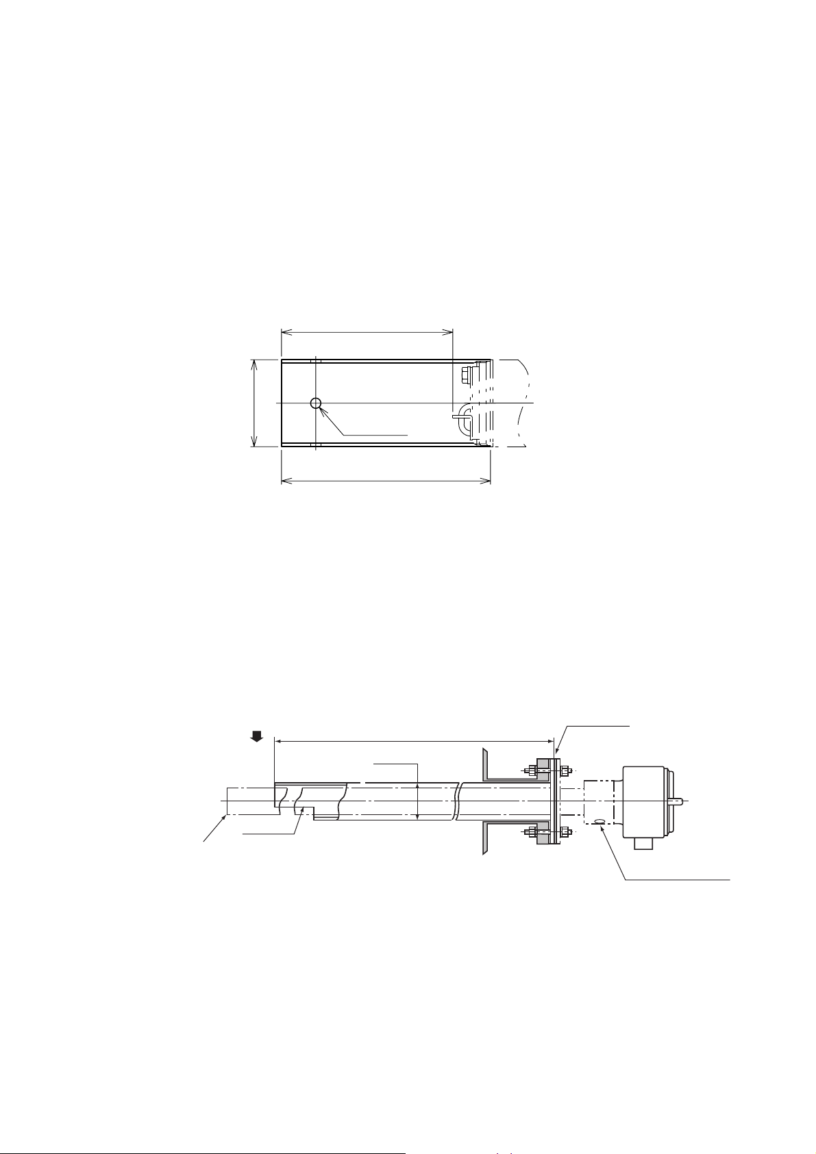
3.1.5 Procedures for installing the dust guard protector (K9471UC)
The ZR22G detector is shipped with the dust guard protector when the option code “/
F2” is specified in case of ordering the detector. The protector should be used when
preventing dusts and water drops from lowering the detector performance is desired.
Screw the protector on the top of the detector so as to cover the top. When attaching or
detaching the protector, perform by hooking holes of its side with a hook pin wrench for
[52-55 hole( Pin diameter 4.5 mm: P/N K9741UX or the like) or by pass a screwdriver
through the holes. When re-attaching the protector after detaching it, apply the “Never
Seize Nickel Special” to it.
Increasing of insertion length
100
50.8
[
4-[6
122
F11-1.eps
3.1.6 Detector with a probe protector (Model ZO21R-L-hhh-h *B for enhance forth
The detector is used with a probe protector to support the probe (ZR22G) when the
probe length is 2.5m or more and it is mounted horizontally.
(1) Put a gasket (provided by the user) between the flanges, and mount the probe
protector in the probe insertion hole.
(2) Make sure that the cell assembly mounting screws (four) at the probe tip are not
loose.
(3) Mount the detector so that the reference gas and calibration gas inlet faces down-
ward.
Flow direction of the
measurement gas
1050,1550,2050
[60.5
Notch
Probe top
Figure 3.3 Probe protector (supporting the mounting strength)
Gasket (t1.5)
Unit: mm
Reference gas inlet
Calibration gas inlet
F3.3E.EPS
3-4
IM 11M12D01-01E
Page 55

3. Installation
3.1.7 Detector with a probe protector (Model ZO21R-L-hhh-h *B for dust wear
protect
The detector is used with a probe protector to prevent the sensor from being worn by
dust particles when there is a high concentration of dust and gas flow exceeds 10m/s
(fine-carbon boiler or fluid-bed furnace).
(1) Put a gasket (provided by the user) between the flanges, and mount the probe
protector in the probe insertion hole. The probe protector should be installed so that
the notch is downstream of the measurement gas flow.
(2) Make sure that the cell assembly mounting screws (four) at the probe tip are not
loose.
(3) Where the detector is mounted horizontally, the reference gas and calibration gas
inlet should face downward.
CAUTION
When the probe protector is used in the Zirconia Oxygen Analyzer version with
pressure compensation (-P), instrument air leaking from the probe protector may
affect the measured value.
1050,1550,2050
Direction of the measurement gas flow
Probe top
Mount the protector so that the notch is
or the downstream side of the gas flow.
Figure 3.4 Mounting of detector with a probe protector
Gasket (t1.5)
F3.4E.EPS
Unit: mm
Reference gas inlet
Calibration gas inlet
IM 11M12D01-01E
3-5
Page 56

3.2 Installation of the Detector (Model ZR22G-015)
3.2.1 Installation Location
This model detector is used with the High-temperature Probe Adapter (Model ZO21P-H)
when the temperature of sample gas exceeds 7008C, or when it is required due to
maintenance spaces.
The following should be taken into consideration when installing the detector:
(1) Easy and safe access to the detector for checking and maintenance work.
(2) Ambient temperature of not more than 1508C and the terminal box should not be
exposed to radiant heat.
(3) A clean environment without any corrosive gases.
(4) No vibration.
(5) The measured gas should satisfy the specifications described in Chapter 2.
3.2.2 Usage of the High-temperature Probe Adapter (Model ZO21P-H)
During analysis, the surface temperature of the probe adapter should be within the range
from the dew point of the measured gas and 3008C to prevent ejector clogging, gasket
deterioration or bolt scoring.
Where the dew point of the measured gas is not known, keep within the range 2008C to
3008C.
The temperature shall be measured at the probe in the probe adapter and the surface of
the blind flange at the opposite side.
When the surface temperature is not within the above range, the following measures can
be taken to change the temperature.
<When the surface temperature exceeds 3008C>
(1) When the furnace pressure is negative, lower the pressure setting to reduce induction
flow of the measurement gas.
Refer to Section 2.6.3, Auxiliary Ejector for High Temperature, for the setting of
induction flow.
When you reduce induction flow, ensure that the ejector inducts air when the furnace
pressure fluctuates.
(2) When the furnace pressure is positive, close the needle valve for the sample gas
outlet to reduce the exhaust gas flow. Refer to Section 4.1.4, Piping to the High-
temperature Probe Adapter.
(3) When the probe adapter is surrounded by a heat insulator, remove the heat insulator.
Ensure that the temperature of the probe adapter does not fall below the dew point of
the gas in winter.
(4) To prevent temperature rises due to radiant heat, insert heat insulator between the
wall of the furnace and the probe adapter.
(5) To prevent temperature rises from thermal conduction, place the mounting flange as
far from the wall of the furnace as possible.
3-6
IM 11M12D01-01E
Page 57

<When the surface temperature is less than 2008C or the dew point of the measure-
ment gas>
(1) When the furnace pressure is negative, raise the analyzer pressure to increase
induction flow of the measurement gas.
Refer to Section 2.6.3, Auxiliary Ejector for High-temperature Use, for the setting of
induction flow.
If there is much dust in the gas, the ejector may become clogg is induction flow
increases.
(2) When the furnace pressure is positive, open the needle valve for the sample gas
outlet to increase the gas flow.
Refer to Section 4.1.4, Piping to the High-temperature Probe Adapter.
(3) Warm the probe adapter. Refer to Section 4.2.4, Piping to the High-temperature
Probe Adapter. Ensure that its temperature does not drop below freezing point in
winter.
(4) When the surface temperature is still less than 2008C or the dew point of the mea-
surement gas, even if the above measures have been taken, warm the probe adapter
using a heat source such as steam.
3.2.3 Probe Insertion Hole
A high-temperature detector consists of a ZR22G-015 Detector and ZO21P Hightemperature Probe Adapter. When forming the probe insertion hole, the following should
be taken into consideration:
3. Installation
100mm
(1) If the probe is made of silicon carbide (SiC), the probe hole should be formed so that
the probe is mounted vertically (no more than a 58 tilt).
(2) In the case where the probe is made of stainless steel and the probe adapter is to be
mounted horizontally, the probe hole should be formed so that the probe tip is not
higher than the probe base.
Figure 3.5 illustrates examples of the probe insertion hole.
JIS 5K 50 FF (equivalent) or
ANSI Class 150 4 RF
(equivalent) flange
A space of 52 mm or more
in diameter, and
for
the length of the probe
The allowable margin for probe
tilt is within658.
An SiC probe shall be mounted vertically.
long enough
Figure 3.5 Examples of the probe insertion hole
A space of 52 mm or
more in diameter, and
long enough the length
of the probe
Never mount the probe
with its tip higher than
the base
Horizontal mounting is used with a SUS probe.
100mm
JIS 5K 50 FF (equivalent)
or ANSI Class 150 4 RF
(equivalent) flange
F3.5E.EPS
IM 11M12D01-01E
3-7
Page 58

3.2.4 Mounting of the High-Temperature Detector
Note
Ceramic (zirconia) is used in the sensor (cell) portion on the detector probe tip. Care
should be taken not to drop the detector during installation.
The same applies to a probe made of silicon carbide (SiC).
A gasket should be used on the flange surface to prevent gas leakage. The gasket
material should be selected depending on the characteristics of the measurement gas. It
should be heatproof and corrosion-proof. The parts, which should be supplied by the
user, are listed in Table 3.2.
Table 3.2 Accessories for mounting high-temperature probe adapter
Mounting flange specification Accessory name Number Note
JIS 5K 50 FF (equivalent) Gasket 1 Heatproof and corrosionproof
Bolt (M12 by 50) 4
Nut (M12) 4
Washer (for M12) 8
ANSI Class 150 RF (equivalent) Gasket 1 Heatproof and corrosionproof
Bolt (M16 by 60) 8
Nut (M16) 8
Washer (for M16) 16
A high-temperature detector should be mounted as follows:
T3.2E.EPS
(1) It is recommended to mount the detector vertically. When it is impossible due to the
physical arrangements and the detector is mounted horizontally, ensure that the probe
tip be placed no higher than the probe base.
(2) When mounting a high-temperature probe adapter, be sure to insert a gasket between
the flanges to prevent gas leakage. When the furnace pressure is negative, ensure that
there is no leakage of air into the furnace.
(3) When mounting the detector in a position other than vertical, the cable inlet should
face downward.
(4) When installing the detector in a low-temperature location such as in the open air,
cover the probe adapter including the ejector with a heat insulator (e.g. ceramic
wool) to keep it warm and to prevent condensation of drain on the ejector.
Wiring connection
Mount the probe so that
the probe tip is not higher
than the probe base.
Wiring connection
3-8
When using an SiC probe, mount the probe vertically
with an allowable tilt of ±5°.
F3.6E.EPS
Figure 3.6 Mounting of the High-temperature Detector
IM 11M12D01-01E
Page 59

3.3 Installation of the Averaging Converter
The averaging converter is designed for indoor installation and should be installed in the
instrument panel in a control room. For outdoor installation, the averaging converter
should be installed in an outdoor instrument panel protected from direct sunlight and the
weather.
DANGER
High voltages are present inside the averaging converter. To prevent unintentional
opening of the front cover, it is securely attached by a lock screw on the right side of
the case. Loosen the lock screw to remove the front cover, and securely tighten the
lock screw after the front cover has been attached.
How to remove the front cover
• Loosen the 4 knob bolts by hand, and then loosen the lock screw with the Allen
wrench supplied.
• Remove the front cover by lifting up slightly then pulling away from the case.
3. Installation
How to attach the front cover
• Attach the front cover, aligning the slots on the sides of the cover with the knob bolts
on the case, and then pull the cover down until it is seated firmly.
• Hand tighten the knob bolts, and then securely tighten the lock screw with the Allen
wrench supplied.
Knob Bolt
Lock Screw
IM 11M12D01-01E
Figure 3.7 How to Remove/Attach the front Cover
3-9
Page 60

3.3.1 Installation Location
Follow the guidelines below when selecting a location for the averaging converter.
(1) The touch screen display should be clearly visible and easily accessible for key
operation: the display at eye level is recommended.
(2) A wall or construction should be strong enough to support the weight of the
converter.
(3) The converter should be easily accessible for inspections and maintenance.
(4) The ambient temperature should be in the range of -5 to 508C and the temperature
variation should be small: the daily temperature range within 158C is recommended.
(5) The humidity should be in the range of 10 to 85%RH and no condensation may
occur.
(6) No corrosive gases are present.
(7) No dust exists.
(8) There is minimal vibration.
(9) The converter should be near the detectors: the two-way resistance between detector
and converter should not exceed 10V.
DANGER
• The averaging converter is heavy. Take extra care not to accidentally drop it.
Installation work should be done by an adequate number of people.
CAUTION
The averaging converter is heavy (100/115 VAC version: approx. 13 kg, 230 VAC
version: approx. 25 kg) so needs to be installed on a wall or construction strong
enough to support.
3.3.2 Installation in an Instrument Panel
When installing the averaging converter in an instrument panel, operability,
maintainability, and environmental resistance should be considered.
(1)Installation Space and Relationship to Peripheral Devices
Follow the instructions below to determine the positions of the averaging converter and
peripheral devices.
• Do not place heat-generating devices in close proximity of the averaging converter:
specially, avoid a place under the averaging converter.
• Do not place power related devices such as transformers or electromagnetic switches
in close proximity of the averaging converter.
• Segregate wiring ducts for signal lines and those for power lines and do not place in
close proximity.
Figure 3.8 shows the requirements for the mounting holes for the averaging converter.
See Section 2.4 for the dimensions of the averaging converter and maintenance
clearance.
3-10
IM 11M12D01-01E
Page 61
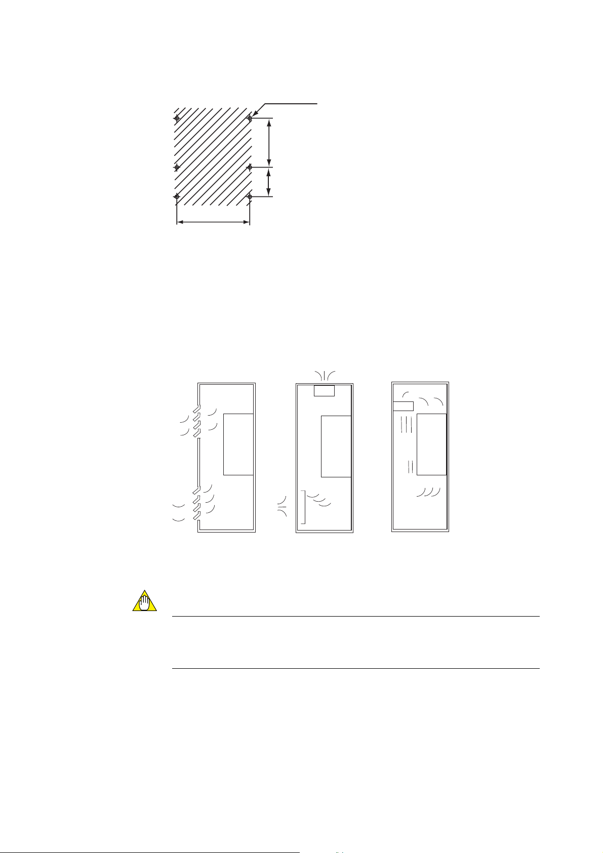
6-M5 screws
300 [267]
150 [165]
3. Installation
Unit: mm
465
Note: Dimensions in inches are
given in parentheses.
F3302.EPS
Figure 3.8 Mounting holes
(2)Preventing Excessive Temperature Rise in an Instrument Panel
Use a cooling method such as one of those shown in Figure 3.9 if there is a danger of
the temperature inside an instrument panel exceeding the temperature range limits.
£
£
£
£
£
£
£
£
£
£
AV550G
£
£
£
Fan
£
£
£
£
AV550G
£
£
£
£
£
£
£
£
AV550G
£
£
Air Filter
£
£
IM 11M12D01-01E
Forced air circulationForced air ventilationNatural air cooling
Figure 3.9 Preventing Excessive Temperature Rise in Panel
CAUTION
If an internal temperature rise alarm occurs, use a more effective method to cool the
inside of an instrument panel down to within the converter operating temperature
range.
3-11
Page 62

3.3.3 Outdoor Installation
The averaging converter is designed for indoor installation. For outdoor installation, the
averaging converter should be housed in an outdoor case protected from direct sunlight
and the weather. The outdoor case should be equipped with a cooling system for
controlling the internal temperature, if necessary. Also, the outdoor case should be
installed in a location that keeps the case free from corrosive gases or dust.
CAUTION
If an internal temperature rise alarm occurs, use a more effective method to cool the
inside of an outdoor case down to within the converter operating temperature range.
3-12
IM 11M12D01-01E
Page 63

3.4 Installation of ZA8F Flow Setting Unit
3.4.1 Location
The following should be taken into consideration:
(1) Easy access to the unit for checking and maintenance work.
(2) Near to the detector and the converter
(3) No corrosive gas.
(4) An ambient temperature of not more than 558C and little changes of temperature.
(5) No vibration.
(6) Little exposure to rays of the sun or rain.
3.4.2 Mounting of ZA8F Flow Setting Unit
The flow setting unit can be mounted either on a pipe (nominal JIS 50A) or on a wall. It
should be positioned vertically so that the flowmeter works correctly.
<Pipe Mounting>
(1) Prepare a vertical pipe of sufficient strength (nominal JIS 50A: O.D. 60.5 mm) for
mounting the flow setting unit. (The unit weighs approximately 2 to 3.5 kg.)
(2) Mount the flow setting unit on the pipe by tightening the nuts with the U-bolt so that
the metal fitting is firmly attached to the pipe.
3. Installation
IM 11M12D01-01E
F3.12E.EPS
Figure 3.10 Pipe Mounting
3-13
Page 64

<Wall Mounting>
(1) Make a hole in the wall as illustrated in Figure 3.11.
Unit : mm
223
140
F3.13E.EPS
4 - f6.5 hole, or M6 screw
Figure 3.11 Mounting holes
(2) Mount the flow setting unit. Remove the pipe mounting parts from the mount fittings
of the flow setting unit and attach the unit securely on the wall with four screws.
F3.14E.EPS
Figure 3.12 Wall mounting
3-14
IM 11M12D01-01E
Page 65

3.5 Installation of the Calibration Gas Unit Case
The calibration gas unit case is used to store the G7001ZC zero gas cylinders.
3.5.1 Location
The following should be taken into consideration:
(1) Easy access for cylinder replacement
(2) Easy access for checking
(3) Near to the detector and converter as well as the flow setting unit.
(4) The temperature of the case should not exceed 408C due to rays of the sun or
radiated heat.
(5) No vibration
3.5.2 Mounting
Mount the calibration gas unit case on a pipe (nominal JIS 50A) as follows:
(1) Prepare a vertical pipe of sufficient strength (nominal JIS 50A: O.D. 60.5 mm) for
mounting the flow setting unit. (The sum of the calibration gas unit case and the
calibration gas cylinder weighs approximately 4.2 kg.)
(2) Mount the unit case on the pipe by tightening the nuts with the U-bolt so that the
metal fitting is firmly attached to the pipe.
3. Installation
IM 11M12D01-01E
A pipe to be mounted
(nominal JIS 50A : O.D. 60.5 mm)
F3.16E.EPS
Figure 3.13 Pipe Mounting
3-15
Page 66

3-16
IM 11M12D01-01E
Page 67

4. Piping
This chapter describes piping procedures for the AV550G Zirconia Oxygen Analyzer
Averaging Converter system based on two typical system configurations.
4.1 Piping for a System Using Flow Setting Units for
Manual Calibration
The piping for a system using flow setting units for manual calibration is shown in
Figure 4.1.
ZR22G Detector (max. 8 detectors)
Cell output, thermocouple output, cold contact compensation
2
, 6-core)
(0.75mm
Heater
2
, 2-core)
(1.25mm
Model AV550G Averaging Converter
Analog outputs :
Averaged and individual outputs
4 to 20 mA DC
4. Piping
Contact output
Check
Valve
K9292DN
K9292DS
Reference gas
Calibration gas
Flowmeter
Model ZA8F
flow setting unit
Needle
Valve
Airset
Calibration gas
pressure regulator
Zero gas cylinder
Instrument air
Span gas (Calibration gas unit same as for zero gas)
Calibration gas unit case
Contact input
Power supply :
100 / 115 V AC, 50 / 60 Hz65%
Figure 4.1 Typical Piping for System Using Flow Setting Units for Manual
Calibration
F01.EPS
IM 11M12D01-01E
4-1
Page 68

The following outlines some points to note regarding the piping for this system.
• Install a stop valve through a nipple on the calibration gas inlet of the detector.
Note: The stop valve should be connected directly to the detector. If any piping is
present between the detector and the stop valve, condensation may develop in
the pipe, causing damage to the detector by rapid cooling when the calibration
gas is introduced.
• When a high temperature detector is used and the pressure of a sample gas is negative,
connect an auxiliary ejector on the sample gas outlet of the high temperature probe
adapter. (See Figure 4.3 in Subsection 4.1.4.)
• When a high temperature detector is used and the pressure of a sample gas is 0.49 Pa
or higher, it is recommended that a throttle (e.g., needle valve) be installed on the
sample gas outlet of the high temperature probe adapter. (See Figure 4.4 in Subsection
4.1.4.)
Note: This is to lower the temperature of a sample gas below 7008C. When both the
temperature and the pressure of a sample gas are high, the temperature of the
sample gas may not fall below 7008C before the gas reaches the detector. On
the other hand, the temperature of a sample gas may drop too much and thus
condensation develops in the high temperature probe ejector. During wintertime,
it is recommended that the probe adapter be protected with an insulating
material to prevent condensation.
• When a high temperature detector is used and blowback is required to eliminate dust
accumulating in the probe of the high temperature probe adapter, air supply piping for
purging should be installed.
Note: If a sample gas contains much dust (e.g., in recovery boilers or cement kilns),
the probe is more likely to become clogged. To eliminate this dust accumulation
using air pressure, piping is generally installed from an air source only when
cleaning is performed. Some cases, however, may need a permanent installation
of the blowback piping. See Subsection 4.1.5 for the installation of blowback
piping.
4-2
IM 11M12D01-01E
Page 69

4.1.1 Parts Required for Piping in a System Using Flow Setting Units for Manual
Calibration
Referring to Table 4.1, check that the parts required for your system are ready.
Table 4.1
Detector Piping Location Part Description
General-purpose Calibration gas inlet Stop valve Yokogawa recommended:
detector L9852CB or G7016XH
* Nipple Rc1/4 or 1/4 NPT General
Tube fitting Rc1/4 (1/4NPT) for a f6 3f4mm General
soft tube
Reference gas inlet (sealed up) (when piping is required, refer to § 4.1.3)
High-temperature Calibration gas inlet Stop valve Yokogawa recommended:
detector L9852CB or G7016XH
* Nipple Rc1/4 or 1/4 NPT General
Tube fitting Rc1/4 (1/4 NPT) for a f6 3f4mm soft tube
Reference gas inlet (sealed up) (when piping is required, refer to § 4.1.3)
Sample gas outlet * Auxiliary ejector Yokogawa recommended,
E7046EC or E7046EN
* Equal tee, connection R1/4 or 1/4 NPT General
fitting
* Needle valve Rc1/4 or 1/4 NPT General
* Reducing nipple R1/2 to R1/4 or R1/2 to 1/4 NPT General
4. Piping
Note: Parts marked with an asterisk (*) are used when required.
General parts are commercially available.
4.1.2 Piping for the Calibration Gases
This piping is to be installed between the zero gas cylinder and the ZA8F flow setting
unit, and between the ZA8F flow setting unit and the ZR22G detector.
The cylinder should be placed in a calibration gas unit case or the like to avoid any
direct sunlight or radiant heat so that the gas cylinder temperature does not exceed 408C.
Mount a regulator valve (specified by YOKOGAWA) on the cylinder.
Mount a check valve or stop valve (specified by YOKOGAWA) on the nipple (found on
the open market) at the calibration gas inlet of the detector as illustrated in Figure 4.8.
(The check valve or the stop valve may have been mounted on the detector when
shipped.) Connect the flow setting unit and the detector to a stainless steel pipe 6 mm
(O.D.) ~ 4 mm or larger (I.D.) (or nominal size 1/4 inch).
Tube connection
joint
T4.1E.EPS
NippleStop valve
IM 11M12D01-01E
F4.2E.EPS
Figure 4.2 Connection to the calibration gas inlet
4-3
Page 70

4.1.3 Piping for the Reference Gas
This piping is to be installed between the zero gas cylinder and the ZA8F flow setting
unit, and between the ZA8F flow setting unit and the ZR22G detector.
The cylinder should be placed in a calibration gas unit case or the like to avoid any
direct sunlight or radiant heat so that the gas cylinder temperature does not exceed 408C.
Mount a regulator valve (specified by YOKOGAWA) on the cylinder.
Mount a check valve or stop valve (specified by YOKOGAWA) on the nipple (found on
the open market) at the calibration gas inlet of the detector as illustrated in Figure 4.8.
(The check valve or the stop valve may have been mounted on the detector when
shipped.) Connect the flow setting unit and the detector to a stainless steel pipe 6 mm
(O.D.) ~ 4 mm or larger (I.D.) (or nominal size 1/4 inch).
4.1.4 Piping to the High Temperature Probe Adapter
A sample gas should be at a temperature below 7008C before it reaches the detector.
Also, a sample gas needs to be sucked if its pressure is negative. The piping for these
purposes should be connected to the high temperature probe adapter. For the use of the
probe adapter when the high temperature detector is used, refer to Subsection 3.2.2.
• If the pressure of a sample gas is negative, connect an auxiliary ejector (E7046EC/
E7046EN) as shown in Figure 4.3. Mount the pressure gauge as close as possible to
the auxiliary ejector. However, if the ambient temperature is too high, mount the
gauge in a location with a temperature below 408C.
Auxiliary ejector for
high temperature use
Adapter for
high temperature probe
Detector
F4.3E.EPS
Figure 4.3 Mounting the auxiliary ejector
• If the temperature of a sample gas is high and its pressure exceeds 0.49 Pa, the
temperature of the sample gas at the detector may not be below 7008C. In this case,
connect a needle valve (commercially available) through a nipple (commercially
available) to the sample gas outlet (Rc1/2) of the probe adapter so that the sample gas
exhaust volume can be restricted. In cases where condensation is likely to occur in the
probe adapter when the sample gas is cooled, protect the probe adapter with an
insulating material as shown in Figure 4.5.
4-4
IM 11M12D01-01E
Page 71

4. Piping
Reducing nipple
(R1/2-R1/4 or R1/2-1/4NTP)
Needle valve
F4.4E.EPS
Figure 4.4 Mounting the needle valve for restricting exhaust flow of the sample
gas
Cover flange
Sample gas outlet
Adapter for high temperature probe
Detector
Probe
Figure 4.5 Preventing to condensation
Insulating material
F4.5E.EPS
IM 11M12D01-01E
4-5
Page 72

4.1.5 Pipinf for Blowback
This piping is required when the blow back function is carried out. The piping described
below provides automatic blow back operation when the “ blow back start “ command is
entered to the converter.
Pipe coupling
Blowback air
Solenoid valve
Regulator valve
Solenoid valve
Blow pipe
Note
If blowback is done under control of a
contact output from the averaging
converter, a hold is placed on analog
output signals from all detector while
blowback is in progress.
See Section 10.5 for details on the
blowback function. Wiring for solenoid
valves is described in Section 5.3.
F4302.EPS
Figure 4.6 Blowback Piping
The following parts are required for blow back piping.
• Blow pipe (to be prepared as illustrated in Figure 4.7.)
• Two-way solenoid valve: “ Open “ when electric current is on. (Found on the open
market)
• Air set (recommended by YOKOGAWA, G7011XF / E7040EL or G7004XF / K9473XG)
<Blow pipe manufacturing>
Manufacture the blow pipe as illustrated in Figure 4.7, and mount it on the hightemperature probe adapter.
4-6
Blind flange of the adapter for
Rc1/4
Approximately
200
high temperature probe
Welded
8 (O.D.) by 6 (I.D.) Stainless steel pipe
Figure 4.7 Blow pipe Construction
Unit : mm
F4.11E.EPS
IM 11M12D01-01E
Page 73

4.1.6 Piping for Indication check
To perform an indication check using the third check gas, the piping to allow the third
gas to flow into the calibration gas line is required for the ZA8F Flow Setting Unit in
addition to the system configuration shown in Figure 4.1.
Connect the piping from the third check gas cylinder through a pressure reducing valve
and a stop valve, along with the span gas line, to the zero gas inlet of the ZA8F Flow
Setting Unit. To perform an indication check, open the stop valve on the line from the
third gas cylinder, while open the stop valve on the span gas line to perform span point
calibration.
Flowmeter
Reference gas
line
Calibration gas
line
Needle valve
ZA8F flow setting unit
4. Piping
Reference gas
line
Calibration gas
line
Flowmeter
Needle valve
ZA8F flow setting unit
Air Set
Stop valve
Pressure regulator
Instrument air
Span gas cylinder
(Instrument air)
Zero gas cylinder
Third check gas cylinder
Figure 4.8 Piping to ZA8F Flow Setting Unit for Indication Check Using 3rd
Check Gas
F3.eps
IM 11M12D01-01E
4-7
Page 74

4.1.7 Piping to Introduce Purge Gas When a Process Gas Alarm Occurs
When a process gas alarm (an input contact signal of unburnt gas detection) occurs, the
averaging converter will cut off the power supply to the heater of the detector, and at the
same time it will send a contact output to activate a solenoid valve for introducing a
purge gas to the detector.
In addition to the system configuration shown in Figure 4.1, a purge gas cylinder and a
pressure reducing valve, and where necessary, a stop valve, a flowmeter, and a needle
valve are required. Also, a check valve should be installed on the calibration gas inlet of
the detector. A typical piping diagram for purging is shown in Figure 4.9.
It is recommended that each instrument be installed to allow for minimum piping
between the ZA8F Flow Setting Unit and the detector and between the solenoid valve
for introducing the purge gas and the detector.
Flowmeter
Needlu valve
Detector
Signal
Heater
Check valve
Calibration gas line
To ZA8F
Reference gas line
Check valve
Calibration gas line
To ZA8F
Reference gas line
Solenoid valve
Figure 4.9 Typical Piping for Purging
Averaging Converter (AV550G)
Contact output
Stop valve
Pressure regulator
Analog outputs:
(Averaged and individual outputs)
Contact output
Contact input
Power supply
purging gas cylinder
4-8
IM 11M12D01-01E
Page 75
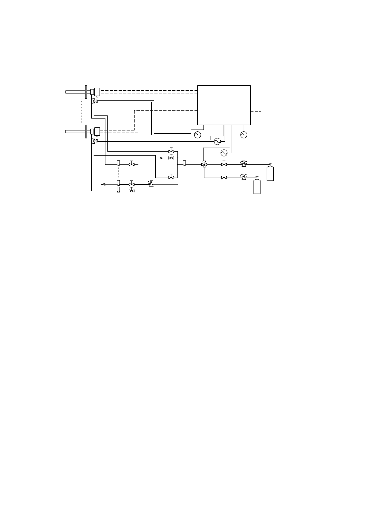
4. Piping
4.2 Piping for a System to Perform Automatic Calibration
The piping for a system to perform automatic calibration is shown in Figure 4.10.
Detector
Reference gas
line
Averaging Converter (AV550G)
Calibration contact outputs
Solenoid valve
Flowmeter
Analog outputs:
Averaged and individual outputs
Contact output
Contact input
Power supply
Span gas cylinder
(Instrument air)
Pressure regulator
Stop valve
Zero gas cylinder
Solenoid valve
Flowmeter
Signal
Heater
Calibration gas line
Needle valve
Needle valve
Instrument air
Air set
Figure 4.10 Typical Piping for a System to perform Automatic Calibration
The following outlines some points to note regarding the piping for this system.
• Install a solenoid valve through a nipple on the calibration gas inlet of the detector.
Note: The solenoid valve should be connected directly to the detector. If any piping is
present between the detector and the solenoid valve, condensation may develop
in the pipe, causing damage to the detector by rapid cooling when the
calibration gas is introduced.
• When a high temperature detector is used and the pressure of a sample gas is negative,
connect an auxiliary ejector on the sample gas outlet of the high temperature probe
adapter. (See Figure 4.3 in Subsection 4.1.4.)
• When a high temperature detector is used and the pressure of a sample gas is 0.49 Pa
or higher, it is recommended that a throttle (e.g., needle valve) be installed on the
sample gas outlet of the high temperature probe adapter. (See Figure 4.4 in Subsection
4.1.4.)
Note: This is to lower the temperature of a sample gas below 7008C. When both
the temperature and the pressure of a sample gas are high, the temperature of
the sample gas may not fall below 7008C before the gas reaches the detector.
On the other hand, the temperature of a sample gas may drop too much and thus
condensation develops in the high temperature probe ejector. During wintertime,
it is recommended that the probe adapter be protected with an insulating
material to prevent condensation.
Note: If optional 24 V outputs are specified for solenoid valves (Option Code "/24"),
no external power supply for solenoid valve is required. The solenoid valves
are powered from the AV550G Averaging Converter. Never connect external
power sources in the wiring for solenoid valves.
• When a high temperature detector is used and blowback is required to eliminate dust
accumulating in the probe of the high temperature probe adapter, air supply piping for
purging should be installed.
Note: If a sample gas contains much dust (e.g., in recovery boilers or cement kilns),
the probe is more likely to become clogged. To eliminate this dust accumulation
using air pressure, piping is generally installed from an air source only when
cleaning is performed. Some cases, however, may need a permanent installation
of the blowback piping. See Subsection 4.1.5 for the installation of blowback
piping.
IM 11M12D01-01E
4-9
Page 76

4.2.1 Parts Required for Piping in a System to Perform Automatic Calibration
Referring to Table 4.2, check that the parts required for your system are ready.
Table 4.2 Parts Required for Piping in a System to Perform Automatic Calibration
Detector
General purpose detector
High temperature detector
Note: Parts marked with an asterisk (*) are used when requored.
General parts are commercially available
Piping Location
Calibration gas inlet
Reference gas inlet
Calibration gas inlet
Reference gas inlet
Sample gas outlet
Solenoid valve
* Nipple
Flowmeter
Needle valve
Tee fitting
Solenoid valve
* Stop valve
Zero gas cylinder
Pressure reducing valve
Connection fitting
Flowmeter
* Needle valve
Air set
Connection fitting
Solenoid valve
* Nipple
Flowmeter
Needle valve
Tee fitting
Solenoid valve
* Stop valve
Zero gas cylinder
Pressure reducing valve
Connection fitting
Flowmeter
* Needle valve
Air set
Connection fitting
* Auxiliary ejector
* Equal tee, connection fitting
* Needle valve
* Reducing nipple
Part Description
Yokogawa recommended: E7057Gh, G700hXP
R1/4 or 1/4NPT(M-M)
0 to 1 L /min
For flow control
For branch connection. Manifold
substitutable
3{way valve for zero/span gas
switching
Yokogawa recommended: G7001ZC
Yokogawa recommended: G7013XF or
G7014XF
R1/4 or 1/4NPT (M)
0 to 1 L /min
For flow control. Unnecessary if
supplied with flowmeter
Yokogawa recommended: G7011XF/E7040EL
or G7004XF/K9473XG
R1/4 or 1/4NPT (M)
Yokogawa recommended: E7046EC or
E7046EN
R1/4 or 1/4NPT (male)
Rc1/4 or 1/4NPT
R1/2-R1/4 or R1/2-1/4NPT
General
General
General
General
General
General
General
General
General
General
General
General
General
General
General
General
General
General
General
General
General
General
General
T4.2E.eps
4-10
IM 11M12D01-01E
Page 77

4.2.2 Piping for the Calibration Gases
The piping for the calibration gases should be installed between the calibration gas
cylinders (or instrument air source) and the detectors with a flowmeter, solenoid valves,
needle valves, and stop valves for performing automatic calibration.
• Place the calibration gas cylinders in a place not exposed to direct sunlight as much as
possible, e.g., house in a gas unit case. The cylinder should be equipped with a
pressure reducing valve (Yokogawa recommended part) and where necessary, a stop
valve.
• Install a normally closed solenoid valve (Yokogawa recommended part) through a
nipple (commercially available) on the calibration gas inlet of the detector as shown
in Figure 4.11. This solenoid valve is activated by a contact signal from the averaging
converter. (Power wiring is separately required.)
Note: If the solenoid valve cannot be connected directly to the calibration gas inlet of
the detector, install a dedicated check valve (K9292DN or K9292DS) on the
inlet and then route the piping to the solenoid valve.
• After installing the solenoid valve on the calibration gas inlet of the detector, route the
piping through a flowmeter, a needle valve, a solenoid valve for switching zero and
span gases, a stop valve, and a pressure reducing valve for the cylinder, in this order,
to the cylinder.
• Install the piping for the solenoid valve for switching zero and span gases so that the
zero gas is introduced to the detector when powered. This solenoid valve is activated
by a contact signal from the averaging converter. (Power wiring is separately
required.)
• Install the needle valve and flowmeter in close proximity as much as possible.
• Use stainless steel pipes with 6 OD x 4 ID mm (or nominal 1/4 inch) or larger inside
diameter for the piping for the calibration gases.
4. Piping
Solenoid valve (nomal close)
Nipple
F4202.EPS
Connect directly to piping inlet
Calibration gas piping
[6 3 [4mm stainless steel pipe
Reference gas piping
[6 3 [4mm
(or nominal 1/4-inch) stainless steel pipe
Figure 4.11 Piping for the Calibration Gas Inlet
IM 11M12D01-01E
4-11
Page 78

4.2.3 Piping for the Reference Gas
The piping for the reference gas should be installed between the air source (instrument
air) and the detector through flowmeters and needle valves for flow control of the
reference air, and an air set.
• Install the piping from the reference gas inlet of the detector to the air source with a
flow meter, a needle valve where necessary, and an air set in this order.
• Install the flowmeter, needle valve and air set in close proximity.
• Use stainless steel pipes with 6 OD x 4 ID mm (or nominal 1/4 inch) or larger inside
diameter for the piping for the reference gas.
4.2.4 Piping to the High Temperature Probe Adapter
The piping to the high temperature probe adapter is required when a high temperature
detector is used.
This piping is the same as the one in the system using flow setting units for manual
calibration. See Subsection 4.1.4.
4.2.5 Piping for Blowback
The piping for blowback is required only when the blowback is conducted in a system
using a high temperature detector. This piping is the same as the one in the system using
flow setting units for manual calibration. See Subsection 4.1.5.
4.2.6 Piping for Indication Check
Detector
Reference
gas line
To perform an indication check using the third check gas, the piping to allow the third
gas to flow into the calibration gas line is required in addition to the system
configuration shown in Figure 4.9.
Route the piping from the third check gas cylinder through a pressure reducing valve
and a stop valve to the solenoid valve for switching the span gas and the third check
gas, as shown in Figure 4.12.
It is recommended that the piping and wiring for the solenoid valve for switching the
span gas and the third check gas be installed to allow the third check gas to be
introduced when powered. This solenoid valve is activated by a contact signal from the
averaging converter (Power wiring is separately required.)
Averaging converter(AV550G)
Calibration
contact outputs
Contact output
p
p
Pressure regulator
p
Solenoid valve
Stop valve
Analog outouts:
(Averaged and individual output)
Contact output
Contact input
Power supply
Span gas cylinder
(Instrument air)
Zero gas cylindr
Third check gas cylinder
Solenoid valve
Flowmeter
Signal
Heater
Calibration gas line
Needle valve
Needle valve
Flowmeter
Instrument air
Air set
4-12
p: If optional 24 V outputs are specified for solenoid valve (MS Code "/24"), no external power supply for solenoid valves is required.
The solenoid valves are powered from the AV550G Averaging Converter. Never connect external power sources in the wiring for
solenoid valves.
Figure 4.12 Piping for Automatic Indication Check Using 3rd Check Gas
IM 11M12D01-01E
Page 79
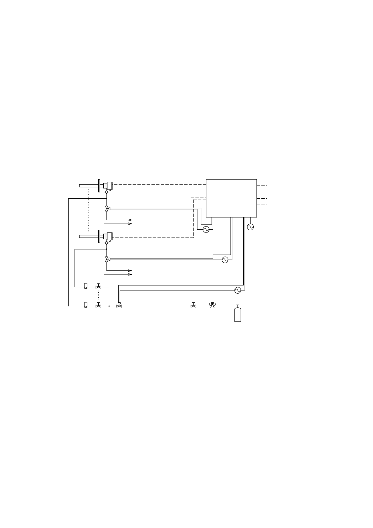
4.2.7 Piping to Introduce Purge Gas When a Process Gas Alarm Occurs
When a process gas alarm (an input contact signal of unburnt gas detection) occurs, the
averaging converter will cut off the power supply to the heater of the detector, and at the
same time it will send a contact output to activate a solenoid valve for introducing a
purge gas to the detector.
The piping for purging in a system to perform automatic calibration is the same as the
one in the system using flow setting units for manual calibration. As instructed in
Subsection 4.1.7, this piping also requires that a check valve be installed on the
calibration gas inlet of the detector. A typical piping diagram for purging is shown in
Figure 4.13.
It is recommended that each instrument be installed to allow for minimum piping
between the solenoid valve for introducing the calibration gases and the check valve,
and between the solenoid valve for introducing the purge gas and the check valve.
4. Piping
Detector
Check valve
Calibration
gas line
Reference
gas line
Check valve
Calibration
gas line
Reference
gas line
Signal
Heater
To calibration gas flow setting
needle valve and flowmeter.
To reference gas flow setting
flowmeter and needlre valve.
To calibration gas flow setting needle valve and flowmeter.
To reference gas flow setting flowmeter and needle valve.
Averaging converter (AV550G)
Calibration contact outputs
Contact output
p
Analog output
(Averaged and individual outputs)
Contact output
Contact input
Power supply
p
Flowmeter
Needle valve
p: If optional 24 V outputs are specified for solenoid valve (MS Code "/24"), no external power supply for solenoid valves is required.
The solenpid valves are powered from the AV550G Averaging Converter. Never connect external power sources in the wiring for
solenoid valvas.
Solenoid valve
Stop valve
Pressure regulator
Purge gas cylinder
Figure 4.13 Typical Piping for Purging
IM 11M12D01-01E
4-13
Page 80

4-14
IM 11M12D01-01E
Page 81

5. Wiring
This chapter describes the wiring connections to the EXAxt AV550G Averaging
Converter.
5.1 General
* Never apply power to the averaging converter and other instruments connected to the
5. Wiring
DANGER
averaging converter until all wiring is completed.
WARNING
• This product complies with the CE marking.
Where compliance with the CE marking is necessary, the following wiring is required.
1. Install an external switch or circuit breaker to the power supply of the averaging
converter.
2. Use an external switch or circuit breaker rated 20A and conforming to IEC 947-1 or
IEC 947-3.
3. It is recommended that the external switch or circuit breaker be installed in the same
room as the averaging converter.
4. The external switch or circuit breaker should be installed within reach of the operator
and identified with marking as a power supply switch to the averaging converter.
5. Power lines such as power cables and heater wires should be fixed securely onto a
wall or construction using cable racks, conduit tubing, nylon bands or other
appropriate ways. Accidental removal from terminals by pulling may result in electric
shock.
IM 11M12D01-01E
5-1
Page 82

5.1.1 Wiring Precautions
5.1.1.1 Precautions Concerning the Correspondence Between Detectors and Channel Cards
Multiple detectors are connected to the averaging converter. Make sure that the wiring is
run properly between the detector and its corresponding channel card on the averaging
converter. Special care should be exercised so that the channel number of the detector
signal line from the channel card corresponds the one of the detector heater line from the
power supply unit. Disagreement may result in malfunction of the detector as well as
invalid operation. (A channel number is indicated in the channel card slot.)
The specified number of channel cards per purchase order is factory installed in channels
in order from CH1. The factory-installed channels can be changed as desired. All the
channels are the same. Note that in a 4-channel base averaging converter (AV550G-A-),
channels CH5 to CH8 cannot be used.
To remove a channel card, loosen the 2 screws attached to the top and bottom of the
card, and then while holding the loosened screws, pull straight away from the slot. To
install a channel card, insert the card by sliding along the guide rail in the slot, and then
securely tighten the 2 screws.
WARNING
• Using a channel card installed without 2 screws tightened, may result in poor
resistance to noise.
5.1.1.2 Precautions in Processing Shields
When a shielded cable is required for wiring, follow the instructions below to process
the shield.
(1) All the shields should be connected on the averaging converter side: Connect to the
cable shield ground terminals inside the averaging converter.
(2) The shields should not be connected on the other side of the cable. To avoid any
possible contact with housings of instruments connected or metal parts, conductors of
the shields should be processed using insulating tapes or in an appropriate way.
(3) The shields should be connected to the cable shield ground terminals immediately
after the cable is inserted into the averaging converter through the wiring hole.
Having a long distance between the wiring hole and the cable end where the shield
goes out, may result in poor resistance to noise.
5-2
IM 11M12D01-01E
Page 83
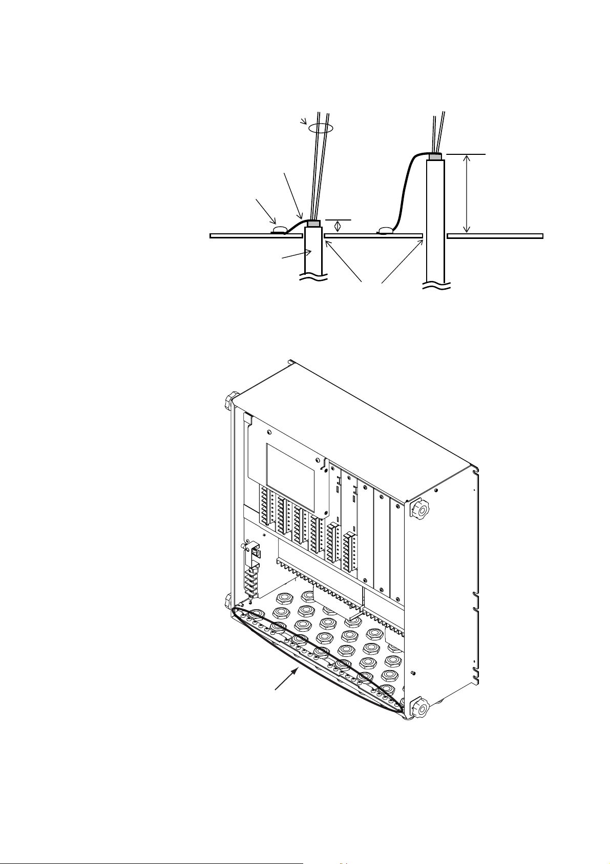
5. Wiring
Cores
Shield
Cable Shield Ground
Terminal
Cable Sheath
Figure 5.1 Shield Processing
Good
To Terminals
Short
Wiring Holes
Bad
To Terminals
Long
IM 11M12D01-01E
Cable Shield Groud Terminals (M4)
Figure 5.2 Cable Shield Ground Terminals
5-3
Page 84

5.1.2 Wiring Holes
The averaging converter has 30 wiring holes. Use holes near the rear for power wiring
(e.g., power cables, detector heater wires, and wiring for solenoid valve contacts and
other contact outputs). For signal wiring (e.g., detector signal lines and analog output
signal lines), use holes near the front.
If more than 30 cables are used and thus more than one cable has to be passed through
one wiring hole, do not allow signal lines and power lines to pass the same hole. Also,
in the averaging converter, the signal lines and power lines should be routed so they can
avoid contact and interference.
A grommet is attached, as standard, to the wiring hole of the averaging converter. An
optional cable gland is available. When a cable gland is not used, make a cable hole in a
grommet.
Wiring Connections: 30 holes
Applicable Cable Hole: [17 mm maximum for grommet
[6 to [12 mm for cable gland (optional)
5.1.3 External Wiring Connection Terminals of the Averaging Converter
The connection diagram of the averaging converter is shown in Figure 5.3. The terminal
numbers are indicated on the converter. Care should be taken to make the wiring
connections correctly.
Averaged
analog outputs
External
ground
terminal
Contact input
Power
supply
Ground
If 230 V AC is selected, channel cards are expandable up to 4.
Control Card
+ 1 + 1 + 1 + 1 + 1
p1
Ave-a
- 2 - 2 - 2 - 2 - 2
+ 3 + 3 + 3 + 3 + 3
Ave-b
- 4 - 4 - 4 - 4 - 4
p2
+ 5 + 5 + 5 + 5 + 5
Ave-c
- 6 - 6 - 6 - 6 - 6
DI1 7 + 7 + 7 + 7 + 7
DI2 8 - 8 - 8 - 8 - 8
COM 9
C NC NO C NC NO C NC NO C NC NO C NC NO
11 12 13 14 15 16 17 19 20 21 22 24 25 26 27 28 29 61 62 63 64 65 66 68 70 71 72
31 32 33 34 35 36 37 39 40 41 42 44 45 46 47 48 49 81 82 83 84 85 86
L
N
G
C NC NO C NC NO C NC NO C NC NO C NC NO C NC NO
DO-CH1
Channel Card (CH1)
CELL
Detector
Output
TC
signals
CJ
Individual
Analog
AO
output
Functional Contact Output
DO1 DO2 DO3
DO-CH2
Individual Error Contact Output
Grounding plate
DO-CH3
51 52 53 54 55 56 57 58 101102 103 104 108
CH1
Common Error output
DO4
18
38
DO-CH4
CH4
CH3
CH2
Cell Heater
Channel Card (CH4) Channel Card (CH5)
Detector
Output
signals
Individual
Analog
output
CELL
TC
CJ
AO
Detector
Output
signals
Individual
Analog
output
Basic Power Supply
Solenoid Valve output
DO5
23
43
SV-COM
Solenoid Valve Contact Output
SV-CH1
SV-CH3
SV-CH2
SV-CH4
CELL
TC
CJ
AO
Individual Error Contact Output
DO-CH5
C NC NO C NC NO
DO-CH7
Individual Error Contact Output
CH5
DO-CH6
DO-CH8
CH6
Cell Heater
Detector
Output
signals
Individual
Analog
output
Expansion Power Supply
Solenoid Valve Contact Output
67 69
87 89
Solenoid Valve Contact Output
105 106
Channel Card (CH8)
CELL
TC
CJ
AO
-CH6
SV-CH5
SV
90 91 92
88
SV-CH8
SV-CH7
107
CH8
CH7
M3.5 screws
M4 screws
G terminal and
Power supply and Ground terminals are M4 screw.
p1 Averged analog output with digital communication (HART) when suffix
code
p2 Used exclusively for communication when suffix code
Fieldbus communication) is selected.
terminal are connected by jumper plate.
“-E”
(HART communication) is selected.
Figure 5.3 External Wiring Connection Terminals of the Averaging Converter
5-4
“-F”
(FOUNDATION
1
1 2 3 4 5 6 2 4 5 6
3
7 8 7 8
Detector
CH1 CH5
Detector
IM 11M12D01-01E
Page 85

5.1.4 Types of Wiring and Cables
Types of wiring and cables to be used are listed in Table 5.1. The purpose of a shield is
not only to prevent the effect from noise disturbance but also to restrict the noise emitted
from the converter. Specified cables must be used.
Table 5.1 Types of Wiring and Cables
5. Wiring
Terminal
Power,
internal grounding
External grounding
Detector heater
Detector signal
Individual analog
output
Averaging analog
output
Solenoid output
Individual error
contact output
Common contact
Indication
L, N,
HTR1 to HTR8
CELL, TC, CJ
AO
A ve-a, A ve-b,
A v3-c
SV-COM, SV-CH1
to SV-CH8
DO-CH1 to
DO-CH8
DO1 to DO4
Shield
Requirement
Unshielded
Unshielded
Shielded
Shielded
Shielded
Shielded
Shielded
Unshielded
Unshielded
Number of
Cores
2 or 3
2
6
2
Note
Note
Note
Note
output
Common error
DO5
Unshielded
Note
contact output
Contact input
DI1, DI2, DI-COM
Unshielded
2 or 3
Note: The number of cores is determined by number of contacts to be used.
Requirements
Size: 2 mm
2
(14 AWG) or larger per core
Either internal grounding or external
grounding will do.
2
Size: 1.25 mm
(16 AWG) or larger,
Conductor two-way resistance: †10 ‰
Conductor two-way resistance: †10 ‰
†550 ‰, including load resistance
Loop resistance when contact is closed:
†200 ‰
IM 11M12D01-01E
5-5
Page 86

5.2 Wiring for the Averaging Converter and Peripheral
Devices
5.2.1 Preparation for Wiring to the Averaging Converter
Follow the instructions below when connecting cables to the averaging converter.
(1) The terminal screws on the control and channel cards are M3.5, and all the other
terminal screws are M4. Each wire should be terminated with a crimp terminal
appropriate to the screw.
(2) If a silicone rubber insulated glass fiber braided wire is used for wiring to the
detector, run the wiring through a terminal box. It is recommended that a cable
such as a PVC insulated PVC sheathed control cable be used between the terminal
box and the averaging converter. This is to prevent moisture or corrosive gases
from entering into the averaging converter and to ensure the grounding of the
detector.
5.2.2 Preparation for Wiring to Detectors
Follow the instructions below when connecting cables to detectors.
(1) Install a conduit or cable gland appropriate to the specified screw size to the cable
inlet of a detector. Allow for the sufficient length of a cable in case that the detector
needs to be removed for maintenance.
(2) If the ambient temperature around the wiring lines exceeds 80˚C, a flexible metal
conduit tube must be used. If an unshielded 600 V silicon rubber insulated glass fiber
braided wire, route the wiring so that the wire cannot pick up external noise.
(3) Figure 5.4 shows the layout of the detector terminals.
TC 1(with Si TUBE)
CELL 1
TC 2
123456
TCCELL CJ
H
T
87
R
Figure 5.4 Detector Terminals
CELL
CELL
(+)
(-)TC(+)TC(-)CJ(+)CJ(-)
To Converter,
or
Terminal Box
To Ground
HTR HTR
To Converter,
or
Terninal Box
5-6
IM 11M12D01-01E
Page 87
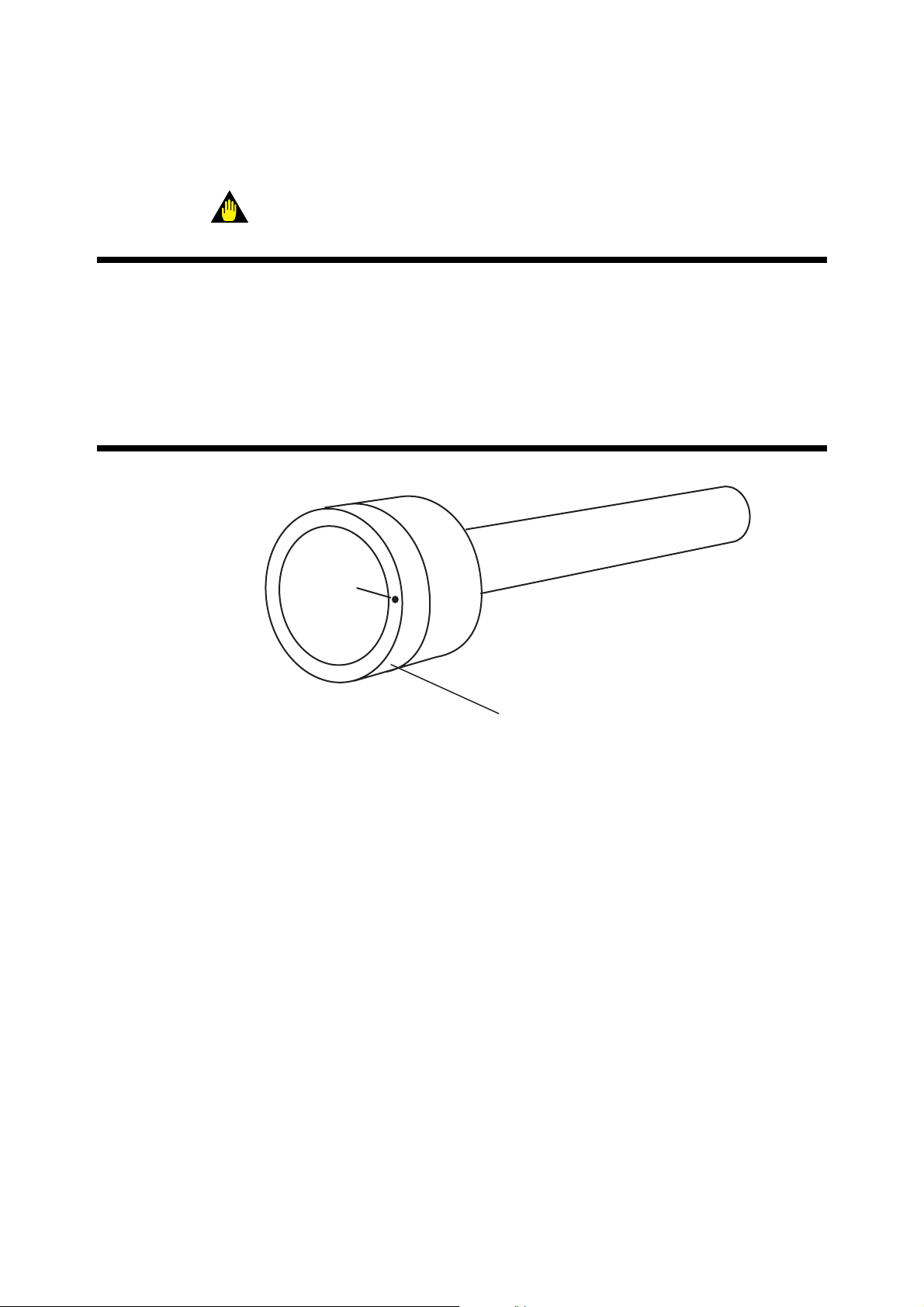
5. Wiring
The sizes of the terminal screws are M3.5. Each wire should be terminated with a crimp
terminal appropriate to the screw.
WARNING
• If the ambient temperature at the detector installation site exceeds 608C, use bare
crimp terminals.
• Before opening the detector cover, loosen the lock screw. If the screw is not loosened
first, the screw will damage the cover, and the terminal box will require replacement.
When opening and closing the cover, remove any sand particles or dust to avoid
gouging the thread.
• Notice when closing the cover of the detector
After screwing the cover in the detector body, secure it with the lock screw.
Lock Screw
Figure 5.5
Detector Cover
F5.8E.EPS
IM 11M12D01-01E
5-7
Page 88

5.2.3 Power and Ground Wiring
Connect the power wiring to the L and N terminals in the averaging converter. Use
wires with a size of 2 mm2 (14 AWG) or larger. If a cable gland is not installed on the
wiring hole of the averaging converter, use a wire with an outside diameter of 17 mm or
smaller. If installed, use a wire with an outside diameter of 6 to 12 mm. A lock washer
must be installed.
Connect the ground wiring to the protective ground terminal in the averaging converter
or the external ground terminal on the side of the case. Run the ground wiring so the
ground resistance is 100 Ω or less (equivalent to Class D grounding).
Make sure that the jumper plate is connected between the G terminal and the protective
ground terminal.
Grounding to the ground terminal
on the Averaging converter case
Converter Case
Crimp T erminal
FG T erminal
Lock Washer
Figure 5.6 Grounding to the Ground Terminal
WARNING
Operating the instrument with the jumper plate disconnected may result in poor
resistance to noise.
5.2.4 Power Wiring to Detector Heaters
This wiring provides electric power from the averaging converter to the heater for
heating the sensor in a detector. Use 2-core shielded PVC insulated PVC sheathed
control cables. The wire size should be 1.25 mm2 (16 AWG) or larger and the conductor
two-way resistance should be 10 Ω or less. If a cable gland is not installed on the wiring
hole of the averaging converter, use a wire with an outside diameter of 17 mm or
smaller. If installed, use a wire with an outside diameter of 6 to 12 mm. The shields
should be connected to cable shield ground terminals on the case of the averaging
converter.
5-8
IM 11M12D01-01E
Page 89

5. Wiring
Detector #1
Averaging Converter
Basic Power Unit
CH1 CH2 CH3 CH4
51 52 53 54 55 56 57 58 7 8
Shield
ZR22G / ZO21D
Detector #2
Detector #3
Detector #4
Figure 5.7 Power Wiring to Detector Heaters
If the ambient temperature at the detector installation site exceeds 80˚C, install a
terminal box and connect to the detector using 600 V silicon rubber insulated glass
braided wires. The distance between the detector and the terminal box should be
minimized.
Detector #1
Averaging Converter
Basic Power Unit
ZR22G / ZO21D
CH1 CH2 CH3 CH4
51 52 53 54 55 56 57 58 7
Shield
Terminal Box
Silicon Rubber Insulated
Glass Braided Wire
Figure 5.8 Power Wiring to Detector Heaters (Using Terminal Box)
W
To Detector #2
To Detector #3
To Detector #4
IM 11M12D01-01E
5-9
Page 90

5.2.5 Signal Wiring to Detectors
This wiring is for transmitting signals of cell electromotive force, thermocouple output
and cold junction compensation from a detector to the averaging converter. Use 6-core
shielded PVC insulated PVC sheathed control cables. The conductor two-way resistance
should be 10 Ω or less. Keep the cables away from the power wiring. If a cable gland is
not installed on the wiring hole of the averaging converter, use a wire with an outside
diameter of 17 mm or smaller. If installed, use a wire with an outside diameter of 6 to
12 mm. The shields should be connected to cable shield ground terminals on the case of
the averaging converter.
Channel Card
CH1
1 1 1 1
1
2
1
2
1
2
CELL
2 2 2 2 1 2 3 4 5 6
3 3 3 3
TC
4 4 4 4
5 5 5 5
CJ
6
Averaging Converter
CH2
6 6 6
CH3
CH4
Shield
Detector #1
ZR22G / ZO21D
Figure 5.9 Signal Wiring to Detectors
To Detecter #2
5-10
IM 11M12D01-01E
Page 91

5. Wiring
If the ambient temperature at the detector installation site exceeds 80˚C, install a
terminal box and connect to the detector using 600 V silicon rubber insulated glass
braided wires. The distance between the detector and the terminal box should be
minimized.
Channel Card
CH1
1
1
CELL
2
2
3
1
TC
4
2
5
1
CJ
6
2
Figure 5.10 Signal Wiring to Detectors (Using Terminal Box)
5.2.6 Ground Wiring of Detectors
Connect the ground wiring to the external ground terminal on the detector case or the
internal ground terminal. Follow the instructions below. The ground terminal screw is
M4.
Averaging Converter
CH2
1
2
3
4
5
6
CH3
Shield
Detector #1
CH4
1
2
3
4
5
6
1
2
3
4
5
6
Terminal Box
ZR22G / ZO21D
12
3456
Silicon Rubber Insulated Glass Braided Wire
To Detector #2
(1) The ground resistance should be 100 Ω or less (equivalent to Class D grounding).
(2) If the ambient temperature of the wiring installation exceeds 80˚C, use appropriate
heat resistant wires.
WARNING
The flange bolts alone do not provide durable grounding of the detector. Be sure to
grounded the ground terminal.
IM 11M12D01-01E
5-11
Page 92

5.2.7 Wiring for Individual and Average Concentration Analog Outputs
For the signal wiring to analog outputs, use shielded PVC insulated PVC sheathed
control cables. The number of cores is determined by the number of outputs. If a cable
gland is not installed on the wiring hole of the averaging converter, use a wire with an
outside diameter of 17 mm or smaller. If installed, use a wire with an outside diameter
of 6 to 12 mm. Like the signal wiring to detectors, the shields should be connected to
cable shield ground terminals on the case of the averaging converter.
The load resistance from the averaging converter, including the wiring resistance, should
be 550 Ω or less.
Averaging Converter
Control Card
Averaged Analog Output
1
1
Ave-a
2
2
Ave-b
3
1
4
2
1
5
Ave-c
2
6
CH1 CH2 CH4
Individual Analog output
1
7 7 7 7
2
8 8 8 8
Channel Card
CH3
Receiver
1
2
1
2
1
2
1
2
Shield
Shield
Figure 5.11 Wiring for Individual and Average Concentration Analog Outputs
5.2.8 Wiring for Solenoid Valve for Automatic Calibration
This wiring is for operating the solenoid valve to switch zero and span calibration gases
during calibration in the automatic calibration system and for operating the solenoid
valve installed on the calibration gas line to the detector of each channel. The contact
output for solenoid valve is also used for operating the solenoid valve on the blowback
piping. For the wiring and piping of the system, refer to Section 5.3, Wiring and Piping
Examples.
Use shielded PVC insulated PVC sheathed control cables for the wiring for solenoid
valves. The shields should be connected to cable shield ground terminals on the case of
the averaging converter.
If a cable gland is not installed on the wiring hole of the averaging converter, use a wire
with an outside diameter of 17 mm or smaller. If installed, use a wire with an outside
diameter of 6 to 12 mm. Like the signal wiring to detectors, the shields should be
connected to cable shield ground terminals on the case of the averaging converter.
All contact outputs for solenoid valves are voltage free, dry contacts (mechanical relay
contact outputs). The contacts are open under normal conditions (when deenergized).
The contact rating is 250 VAC, 1A or 30 VDC, 1A.
5-12
If optional 24 V outputs are specified for solenoid valves (Option Code "/24"), no
external power supply for solenoid valves is required. The solenoid valves are powered
from the AV550G Averaging Converter. The maximum current that can be supplied to
the solenoid valve is 50 mA. Use solenoid valves that consume not more than 1.2 W to
operate.
IM 11M12D01-01E
Page 93

Averaging Converter
Basic Power Unit Expansion Power Unit
26 27 28 29 69 70 71 72
44 45 46 47 48 49
89 90 91 92
5. Wiring
Solenoid Valve for Switching
Zero/Span Cal Gases
Power Supply to Solenoid Valve
Solenoid Valve for Cal Gas to Detector #1
Power Supply to Solenoid Valve
Solenoid Valve for Cal Gas to Detector #2
Power Supply to Solenoid Valve
: If optional 24 V outputs are specified for solenoid valves (Option Code "/24"),
p
p
p
p
Shield
no external power supply for solenoid valves is required. The solenoid valves
are powered from the AV550G Averaging Converter. Never connect external
power sources in the wiring for solenoid valves.
5.2.9 Wiring for Individual/Common Error Contact Outputs and Common Contact
Outputs
The averaging converter has the following contact outputs.
(1) Common function-specific contact outputs (DO1 to DO4): User specified functions
can be assigned.
(2) Common error contact output (DO5): Activated when any error occurs.
(3) Individual error contact outputs (DO-CH1 to DO-CH8): Channel-specific contacts.
One output is provided per channel.
For details on errors, refer to Section 12.1, "Display and Remedies When Error Occur."
All contact outputs are Form C (transfer contact) and consist of 3 terminals of COM,
NC, and NO. All contacts are voltage free, dry contacts (mechanical relay contact
outputs). The contact rating is 250 VAC, 3A or 30 VDC, 3A.
The individual and common error contacts are set to normally energized and cannot be
changed. The "NC" and "NO" indications on the terminal show energized states. States
of common contacts 1 to 4 are user selectable: normally energized or normally
deenergized. The "NC" and "NO" indications on the terminal show deenergized states.
IM 11M12D01-01E
5-13
Page 94

Use PVC insulated PVC sheathed control cables for the wiring for these outputs. There
is no need to use shielded cables. If a cable gland is not installed on the wiring hole of
the averaging converter, use a wire with an outside diameter of 17 mm or smaller. If
installed, use a wire with an outside diameter of 6 to 12 mm.
Averaging Converter
Basic Power Supply
11 12 13 14 15 16 17 18 19 20 21 22 23 24 61 62 63 64 65 66
31 32 33 34 35 36 37 38 39 40 41 42 43 44 81 82 83 84 85 86
Expansion Power Unit
CH1
Error
CH2
Error
CH3
Error
CH4
Error
Annunciator, etc.
Figure 5.13 Wiring for Individual/Common Error Contact Outputs and Common
Contact Outputs
5-14
IM 11M12D01-01E
Page 95

5.2.10 Wiring for Contact Inputs
The averaging converter receives contact inputs to perform the specified functions.
Follow the instructions below to run the wiring for contact inputs.
Use 2-core or 3-core PVC insulated PVC sheathed control cable for this wiring. The
number of cores is determined by the number of contacts to be used. There is no need to
use shielded cables. If a cable gland is not installed on the wiring hole of the averaging
converter, use a wire with an outside diameter of 17 mm or smaller. If installed, use a
wire with an outside diameter of 6 to 12 mm. Like the signal wiring to detectors, the
shields should be connected to cable shield ground terminals on the case of the
averaging converter.
Contact inputs should be voltage free. The open/closed state of the contact is determined
by the resistance from the averaging converter side. Note that the resistance should
include the wiring resistance.
Closed contact: 200 V or less
Open contact: 100 kV or more
Averaging Converter
Control Card
5. Wiring
7
8
9
Contact Input 1
Contact Input 2
Figure 5.14 Wiring for Contact Inputs
IM 11M12D01-01E
5-15
Page 96

5.3 Wiring and Piping Examples
5.3.1 Wiring and Piping for Automatic Calibration
Detector
Solenoid
Valve
Averaging Converter (AV550G)
p
p
Calibration Gas Line
Reference
Gas Line
Flowmeter
Air Set
Needle Valve
: If optional 24 V outputs are specified for solenoid valves (Option Code 0/240), no external
p
power supply for solenoid valves is required. The solenoid valves are powered from the
AV550G Averaging Converter. Never connect external power sources in the wiring for
solenoid valves.
Figure 5.15 Typical Diagram for Automatic Calibration
Needle Valve
Flow
meter
Instrument Air
Solenoid
Valve
Stop Valve
p
Pressure Regulator
Zero Gas Cylinder
Power Supply
Span Gas Cylinder
(Instrument Air)
5.3.2 Wiring and Piping for Automatic Calibration and 3rd Gas Indication Check
Detector
Solenoid
Valve
Calibration Gas Line
Referece
Gas Line
Flowmeter
Needle Valve
: If optional 24 V outputs are specified for solenoid valves (Option Code 0/240), no external
p
power supply for solenoid valves is required. The solenoid valves are powered from the
AV550G Averaging Converter. Never connect external power sources in the wiring for
solenoid valves.
Figure 5.16 Typical Diagram for Automatic Calibration and 3rd Gas Indication
Averaging Converter (AV550G)
p
Air Set
Needle Valve
Instrument
Air
Flow
meter
p
Solenoid
Valve
Stop Valve
Check
Power Supply
Span Gas Cylinder
p
Pressure Regulator
Third Check Gas Cylinder
Analog Output
(Averaged and Individual Output)
Contact Output
Contact Input
(Instrument Air)
Zero Gas Cylinder
5-16
IM 11M12D01-01E
Page 97

5.3.3 Wiring and Piping for Blowback
Blowback Solenoid Valve
High Temperature
Detector
Stop Valve
Averaging Converter (AV550G)
5. Wiring
Analog Output
(Averaged and Individual Output)
Contact Output
Contact Input
p
Power Supply
p
Calibration
Gas Line
Reference
Gas Line
Calibration
Gas Line
Reference
Gas Line
To ZA8F Flow Setting Unit
To ZA8F Flow Setting Unit
Instrument Air
Air Set
: If optional 24 V outputs are specified for solenoid valves (Option Code 0/240), no external
p
power supply for solenoid valves is required. The solenoid valves are powered from the
AV550G Averaging Converter. Never connect external power sources in the wiring for
solenoid valves.
Figure 5.17 Typical Diagram for Blowback
5.3.4 Wiring and Piping for Automatic Calibration and Blowback
Blowback Solenoid Valve
High Temperature
Detector
Solenoid
Valve
Averaging Converter (aV550G)
Analog Output
(Averaged and Individual Output)
Contact Output
Contact Input
Note : If optional 24 V outputs are specified for solenoid valves (Option Code 0/240), this system cannot be established.
This is because the contact to activate a solenoid valve is used in common for autocalibration and blowback.
IM 11M12D01-01E
Reference
Gas Line
Power Supply
Air Set
Needle Valve
Instrument Air
Flowmeter
Solenoid
Valve
Pressure Regulator
Span Gas Cylinder
(Instrument Air)
Zero Gas Cylinder
Calibration Gas Line
Flowmeter
Needle Valve
Figure 5.18 Typical Diagram for Automatic Calibration and Blowback
5-17
Page 98

5-18
IM 11M12D01-01E
Page 99

6. Components
In this Chapter, the names and functions of components are described for the major
equipment of the AV550G Averaging Converter.
6.1 ZR22G Detector
6.1.1 General-purpose Detector (except for Model ZR22G-015)
Terminal box,
Non explosion-proof JIS
C0920 / equivalent to IP44D.
Equivalent to NEMA 4X/IP66
(Achieved when the cable entry
is completely sealed with a
cable gland in the recirculation
pressure compensated version.)
6. Components
Bolt
Probe
this part is inserted in the furnace.
Select length from 0.4,
0.7, 1.0, 1.5, 2.0, 2.5 or 3.0
3.6, 4.2, 4.8 or 5.4 m.
Contact
Metal O-ring
Pipe support
U-shaped pipe
Sensor (cell)
Filter
Washer (or plain washer)
Figure 6.1 General-use Detector (standard type)
Flange used to mount the detector.
Select from JIS or ANSI
standard models.
Dust filter mounting screw
Calibration gas
pipe opening
Probe
Screw
F0601e.eps
IM 11M12D01-01E
6-1
Page 100

6.1.2 High-Temperature Detector (Model ZR22G-015)
Sample gas outlet
When a negative measurement gas
pressure is used, connect the auxiliary
ejector assembly.
When the measurement gas is
high-temperature and high-pressure,
and does not fall below 7008C,
connect a pressure control valve
(e.g. a needle valve).
(Refer to Section 3.2.2.)
Flange
Selectable from JIS standards
or ANSI standards
Separate type
High-temperature Detector
(ZR22G-015)
When the temperature
of the measurement
gas is between 7008 and 14008C,
mount this detector
with a ZO21P-H probe adapter.
High-temperature Probe Adapter
(ZO21P-H)
The probe is made of either SUS 310S
or silicon carbide (SiC).
Its length is either 1.0 m or 1.5 m.
When using an SiC probe,
mount it vertically downward.
6-2
F0602e.eps
Figure 6.2 High-temperature Detector
IM 11M12D01-01E
 Loading...