

Page 1

User's
Manual
Model ZR22G, ZR402G
Separate type
Zirconia High Temperature Humidity Analyzer
IM 11M12A01-03E
IM 11M12A01-03E
7th Edition
Page 2

Introduction
The EXAxt ZR Separate-type Zirconia High-temperature Humidity Analyzer has been
developed for humidity control in various industrial processes. This analyzer basically
consists of a detector and a converter. You can select between several versions based
upon your application.
Optional accessories are also available to improve measurements and automate calibration. An optimal control system can be realized by adding appropriate options.
This instruction manual refers to almost all of the equipment related to the EXAxt ZR.
You may skip any section(s) on the equipment which is/are not included in your system.
Regarding the HART communication protocol,refer to the IM 11M12A01-51E.
IM 11M12A01-51E has been published as Model EXAxt ZR Series HART Protocol
The all-in-one version (with sensor and analyzer integrated in one body) is described in
IM 11M12A01-05E
< Before using the equipment, please read any related descriptions in this manual for the
equipment and the system you have, on appropriate use and operation of the EXAxt ZR. >
Models and descriptions in this manual are as follows:
Models and descriptions in this manual
Description in this manual
Model Product Name Specification Installation Operation Maintenance CMPL
ZR22G General-use detector s s s s
ZR402G Converter s s s s s
ZH21B Dust protector s s
ZA8F Flow setting unit (for manual calibration use) s s s
ZR40H Automatic Calibration unit s s s s
- Calibration gas unit case (Part No. E7044KF) s s
- Check valve (Part No. K9292DN, K9292DS) s s
ZO21S Standard gas unit s s s s
T.Int.1E
CMPL : Customer Maintenance Parts List
IM 11M12A01-03E
7th Edition: Sep. 2006 (YK)
All Rights Reserved, Copyright © 2000, Yokogawa Electric Corporation
IM 11M12A01-03E
i
Page 3

This manual consists of twelve chapters. Please refer to the reference chapters for
installation, operation and maintenance.
Table of Contents
References
Chapter Outline Installation Operation Maintenance
1. Overview Equipment models and system configuration examples
2. Specifications Standard specification, model code (or part number),
dimension drawing for each equipment
3. Installation Installation method for each equipment
4. Piping Examples of piping in three standard system
configurations
5. Wiring Wiring procedures such as Power supply wiring , output
signal wiring or others
6. Components These are described in this manual
7. Startup Basic procedure to start operation of EXAxt ZR. Chapter 7
enables you to operate the equipment immediately.
8. Detailed Data Setting Details of key operations and displays
9. Calibration Describes the calibration procedure required in the course
of operation.
10. Other Functions Other functions described
11. Inspection and How to conduct maintenance of EXAxt ZR and procedures
Maintenance for replacement of deteriorated parts
12. Troubleshooting This chapter describes measures to be taken when an
abnormal condition occurs.
CMPL (parts list) User replaceable parts list
: Read and completely understand before operating the equipment.
s
: Read before operating the equipment, and refer to whenever necessary.
s
: Recommended to read it at least once.
n
s
s
s
s
s
n
n
s
s
s
s
s
s
s
n
n
s
s
n
n
n
s
n
n
n
n
s
s
s
T.Int.2E
ii
IM 1M12A01-03E
Page 4
r For the safe use of this equipment
CAUTION
The cell (sensor) at the tip of the detector is made of ceramic (zirconia element). Do not
drop the detector or subject it to pressure stress.
• Do NOT allow the sensor (probe tip) to make contact with anything when installing
the detector.
• Avoid any water dropping directly on the probe (sensor) of the detector when installing it.
• Check the calibration gas piping before introducing the calibration gas to ensure that
there is no leakage of the gas. If there is any leakage of the gas, the moisture drawn
from the measuring gas can damage the sensor.
• The detector (especially at the tip) becomes very hot. Be sure to handle it with gloves.
EXAxt ZR is very heavy. Handle it with care. Be sure not to accidentally drop it.
Handle safely to avoid injury.
DANGER
(1) About This Manual
Connect the power supply cord only after confirming that the supply voltage matches
the rating of this equipment. In addition, confirm that the power is switched off when
connecting power supply.
Some process gas is dangerous to people. When removing this equipment from the
process line for maintenance or other reasons, protect yourself from potential
poisoningby using a protective mask or ventilating the area well.
• This manual should be passed on to the end user.
• The contents of this manual are subject to change without prior notice.
• The contents of this manual shall not be reproduced or copied, in part or in whole,
without permission.
• This manual explains the functions contained in this product, but does not warrant that
those will suit the particular purpose of the user.
• Every effort has been made to ensure accuracy in the preparation of this manual.
However, should any errors or omissions come to the attention of the user, please
contact the nearest Yokogawa Electric representative or sales office.
• This manual does not cover the special specifications. This manual may not be
changed on any change of specification, construction and parts when the change does
not affect the functions or performance of the product.
• If the product is used in a manner not specified in this manual, safety of this product
may be impaired.
IM 11M12A01-03E
iii
Page 5
(2) Safety and Modification Precautions
• Follow the safety precautions in this manual when using the product to ensure protection and safety of personnel, product and system containing the product.
(3) The following safety symbols are used on the product as well as in this manual.
DANGER
This symbol indicates that the operator must follow the instructions laid out in this
manual in order to avoid the risk of personnel injuries or fatalities such as electric shock.
The manual describes what special care the operator must exercise to prevent such risks.
WARNING
This symbol indicates that the operator must refer to the instructions in this manual in
order to prevent the instrument (hardware) or software from being damaged, or a system
failure from occurring.
CAUTION
This symbol draws attention to information essential for understanding the operation and
functions.
Tip
This symbol gives information that complements the present topic.
SEE ALSO
This symbol identifies a source to which to refer.
Protective Ground Terminal
Function Ground Terminal (Do not use this terminal as the protective ground
terminal.)
Alternating current
iv
IM 1M12A01-03E
Page 6

• Special descriptions in this manual
This manual indicates operation keys, displays and drawings on the product as follows:
• Operation keys, Enclosed in [ ], displays on the panel 0 0.
• Drawing for flashing
Indicated by gray characters. (Flashing) (lit)
(Ex. [MODE] key)
(Ex. message display 0 BASE 0)
(Ex. data display 0 102 0 lit, 0 102 0 flashing)
IM 11M12A01-03E
v
Page 7

r NOTICE
• Specification check
When the instrument arrives, unpack the package with care and check that the
instrument has not been damaged during transportation. In addition, please check that
the specification matches the order, and required accessories are not missing. Specifications can be checked by the model codes on the nameplate. Refer to Chapter 2
Specifications for the list of model codes.
• Details on operation parameters
When the EXAxt ZR Separate-type High Temperature Humidity Analyzer arrives at
the user site, it will operate based set before shipping parameters (initial data) on the
departure from the factory.
Ensure that the initial data is suitable for the operation conditions before conducting
analysis. Where necessary, set the instrument parameters for appropriate operation.
For details of setting data, refer to chapters 7 to 10.
When user changes the operation parameter, it is recommended to note down the
changed setting data.
r After -Sales Warranty
d Do not modify the product.
d During the warranty period, for repair under warranty carry or send the product to the
local sales representative or service office. Yokogawa will replace or repair any
damaged parts and return the product to you.
d Before returning a product for repair under warranty, provide us with the model
name and serial number and a description of the problem. Any diagrams or data
explaining the problem would also be appreciated.
d If we replace the product with a new one, we won’t provide you with a repair report.
d Yokogawa warrants the product for the period stated in the pre-purchase quotation.
Yokogawa shall conduct defined warranty service based on its standard. When the
customer site is located outside of the service area, a fee for dispatching the maintenance engineer will be charged to the customer.
d In the following cases, customer will be charged repair fee regardless of warranty
period.
• Failure of components which are out of scope of warranty stated in instruction
manual.
• Failure caused by usage of software, hardware or auxiliary equipment, which
Yokogawa Electric did not supply.
• Failure due to improper or insufficient maintenance by user.
• Failure due to modification, misuse or outside-of-specifications operation which
Yokogawa does not authorize.
• Failure due to power supply (voltage, frequency) being outside specifications or
abnormal.
• Failure caused by any usage out of scope of recommended usage.
• Any damage from fire, earthquake, storms and floods, lightning, disturbances, riots,
warfare, radiation and other natural changes.
vi
IM 1M12A01-03E
Page 8

d Yokogawa does not warrant conformance with the specific application at the user
site. Yokogawa will not bear direct/indirect responsibility for damage due to a specific
application.
d Yokogawa Electric will not bear responsibility when the user configures the product
into systems or resells the product.
d Maintenance service and supplying repair parts will be covered for five years after
the production ends. For repair for this product, please contact the nearest sales office
described in this instruction manual.
IM 11M12A01-03E
vii
Page 9

Contents
Introduction........................................................................................................................... i
r For the safe use of this equipment ............................................................................... iii
r NOTICE.........................................................................................................................vi
r After-Sales Warranty ................................................................................................... vi
1. Overview ...................................................................................................................... 1-1
1.1 < EXAxt ZR > System Configuration............................................................ 1-2
1.1.1 System 1 .................................................................................................. 1-2
1.1.2 System 2 .................................................................................................. 1-3
1.1.3 System 3 .................................................................................................. 1-4
1.2 < EXAxtZR > System Components ............................................................... 1-5
1.2.1 System Components ................................................................................ 1-5
1.2.2 Detectors and Accessories ....................................................................... 1-5
2. Specifications ............................................................................................................... 2-1
2.1 General Specifications .................................................................................... 2-1
2.1.1 Standard Specifications ........................................................................... 2-1
2.2 General-use Separate-type Detector and Related Equipment ........................ 2-3
2.2.1 ZR22G General-use Separate-type Detector ........................................... 2-3
2.2.2 ZH21B Dust Protector ............................................................................. 2-8
2.3 ZR402G Separate-type Converter ................................................................... 2-9
2.3.1 Standard Specifications ........................................................................... 2-9
2.3.2 Function ................................................................................................. 2-10
2.4 ZA8F Flow Setting Unit and ZR40H Automatic Calibration Unit ............. 2-16
2.4.1 ZA8F Flow Setting Unit........................................................................ 2-16
2.4.2 ZR40H Automatic Calibration Unit ...................................................... 2-18
2.5 ZO21S Standard Gas Unit ............................................................................ 2-21
2.6 Other Equipment ........................................................................................... 2-22
2.6.1 Stop Valve (Part Number: L9852CB or G7016XH) ............................ 2-22
2.6.2 Check Valve (Part Number: K9292DN or K9292DS) ......................... 2-23
2.6.3 Air Set................................................................................................... 2-24
2.6.4 Zero-gas Cylinder (Part Number: G7001ZC) ....................................... 2-26
2.6.5 Pressure Regulator for Gas Cylinder
(Part Number: G7013XF or G7014XF) .............................................. 2-26
2.6.6 Case Assembly for Calibration-gas Cylinder
(Part Number: E7044KF)..................................................................... 2-27
2.6.7 Model ZR22A Heater Assembly ........................................................... 2-28
3. Installation ................................................................................................................... 3-1
3.1 Installation of the Detector ............................................................................. 3-1
3.1.1 Location ................................................................................................... 3-1
3.1.2 Probe Insertion Hole ................................................................................ 3-2
3.1.3 Installation of the Detector ...................................................................... 3-3
3.1.4 Installation of ZH21B Dust Protector ..................................................... 3-3
viii
IM 1M12A01-03E
Page 10

3.2 Installation of the Converter ........................................................................... 3-4
3.2.1 Location .................................................................................................. 3-4
3.2.2 Mounting of the Converter ...................................................................... 3-4
3.3 Installation of ZA8F Flow Setting Unit ......................................................... 3-7
3.3.1 Location ................................................................................................... 3-7
3.3.2 Mounting of ZA8F Flow Setting Unit .................................................... 3-7
3.4 Installation of ZR40H Automatic Calibration Unit........................................ 3-9
3.4.1 Location ................................................................................................... 3-9
3.4.2 Mounting of ZR40H Automatic Calibration Unit .................................. 3-9
3.5 Installation of E7044KF Case Assembly for
the Calibration-gas Cylinder ......................................................................... 3-11
3.5.1 Location ................................................................................................. 3-11
3.5.2 Mounting................................................................................................ 3-11
3.6 Insulation Resistance Test ............................................................................. 3-12
3.7 External Dimensions of Detectors with Pressure Compensation................. 3-13
4. Piping............................................................................................................................4-1
4.1 Piping for System 1 ........................................................................................ 4-1
4.1.1 Parts Required for Piping in System 1 ................................................... 4-2
4.1.2 Connection to the Calibration Gas Inlet ................................................. 4-2
4.1.3 Connection to the Reference Gas Inlet ................................................... 4-2
4.2 Piping for System 2 ........................................................................................ 4-3
4.2.1 Piping Parts for System 2........................................................................ 4-3
4.2.2 Piping for the Calibration Gas ................................................................ 4-4
4.2.3 Piping for the Reference Gas .................................................................. 4-4
4.3 Piping for System 3 ........................................................................................ 4-5
5. Wiring ........................................................................................................................... 5-1
5.1 General ............................................................................................................ 5-1
5.1.1 Terminals for the External Wiring in the Converter .............................. 5-3
5.1.2 Wiring ...................................................................................................... 5-3
5.1.3 Mounting of Cable Gland........................................................................ 5-4
5.2 Wiring for Detector Output ............................................................................. 5-5
5.2.1 Cable Specifications ................................................................................ 5-5
5.2.2 Connection to the Detector...................................................................... 5-6
5.2.3 Connection to the Converter ................................................................... 5-7
5.3 Wiring for Power to Detector Heater ............................................................. 5-8
5.3.1 Cable Specifications ................................................................................ 5-8
5.3.2 Connection to Detector............................................................................ 5-8
5.3.3 Connection to Converter ......................................................................... 5-9
5.4 Wiring for Analog Output ............................................................................. 5-10
5.4.1 Cable Specifications .............................................................................. 5-10
5.4.2 Wiring Procedure................................................................................... 5-10
5.5 Power and Grounding Wiring....................................................................... 5-11
5.5.1 Power Wiring......................................................................................... 5-11
5.5.2 Grounding Wiring ................................................................................. 5-11
5.6 Wiring for Contact Output............................................................................ 5-12
5.6.1 Cable Specifications .............................................................................. 5-12
5.6.2 Wiring Procedure................................................................................... 5-12
5.7 Wiring for ZR40H Automatic Calibration Unit ........................................... 5-13
5.7.1 Cable Specifications .................................................................................. 5-14
5.7.2 Wiring Procedure ...................................................................................... 5-14
IM 11M12A01-03E
ix
Page 11

5.8 Wiring for Contact Input ............................................................................... 5-15
5.8.1 Cable Specifications .............................................................................. 5-15
5.8.2 Wiring Procedure................................................................................... 5-15
5.9 Temperature Input Wiring ............................................................................ 5-16
5.9.1 Applicable Temperature Transmitter .................................................... 5-16
5.9.2 Cable Specifications .............................................................................. 5-16
5.9.3 Wiring Procedure................................................................................... 5-16
6. Components ................................................................................................................. 6-1
6.1 ZR22G Detector .............................................................................................. 6-1
6.1.1 General-purpose Detector ........................................................................ 6-1
6.2 ZR402G Converter.......................................................................................... 6-2
6.3 ZA8F Flow Setting Unit, ZR40H Automatic Calibration Unit ..................... 6-3
7. Startup..........................................................................................................................7-1
7.1 Checking Piping and Wiring Connections ..................................................... 7-1
7.2 Checking Valve Setup ..................................................................................... 7-1
7.3 Supplying Power to the Converter .................................................................. 7-2
7.4 Touchpanel Switch Operations ....................................................................... 7-3
7.4.1 Basic Panel and Switch ........................................................................... 7-3
7.4.2 Display Configuration (for High-temperature Humidity Analyzer) ....... 7-4
7.4.3 Display Functions .................................................................................... 7-5
7.4.4 Entering Numeric and Text Data ............................................................ 7-5
7.5 Confirmation of Converter Type Setting........................................................ 7-7
7.6 Confirmation of Detector Type Setting .......................................................... 7-8
7.7 Current Output Setting.................................................................................... 7-8
7.7.1 Analog Output Setting ............................................................................. 7-8
7.7.2 Minimum Current (4 mA) and Maximum Current (20 mA) Settings ... 7-9
7.8 Setting Display Item ..................................................................................... 7-10
7.9 Checking Current Loop ................................................................................. 7-12
7.10 Checking Contact I/O ................................................................................... 7-13
7.10.1 Checking Contact Output ...................................................................... 7-13
7.10.2 Checking Calibration Contact Output................................................... 7-14
7.10.3 Checking Input Contacts ....................................................................... 7-14
7.11 Calibration ..................................................................................................... 7-15
7.11.1 Calibration Setup................................................................................... 7-15
7.11.2 Manual Calibration................................................................................ 7-16
8. Detailed Data Setting.................................................................................................. 8-1
8.1 Current Output Setting.................................................................................... 8-1
8.1.1 About Input Ranges ................................................................................. 8-1
8.1.2 Setting Minimum Current (4 mA) and Maximum Current (20 mA) ..... 8-4
8.1.3 Entering Output Damping Constants ...................................................... 8-4
8.1.4 Selection of Output Mode ....................................................................... 8-4
8.1.5 Default Values ......................................................................................... 8-5
8.2 Output Hold Setting ........................................................................................ 8-6
8.2.1 Definition of Equipment Status ............................................................... 8-6
8.2.2 Preference Order of Output Hold Value ................................................. 8-7
8.2.3 Output Hold Setting................................................................................. 8-8
8.2.4 Default Values ......................................................................................... 8-8
x
IM 1M12A01-03E
Page 12

8.3 Alarm Setting .................................................................................................. 8-9
8.3.1 Alarm Values ........................................................................................... 8-9
8.3.2 Alarm Output Actions ............................................................................. 8-9
8.3.3 Alarm Setting Procedure ....................................................................... 8-10
8.3.4 Default Values ....................................................................................... 8-11
8.4 Output Contact Setup .................................................................................... 8-12
8.4.1 Output Contact....................................................................................... 8-12
8.4.2 Setting Procedure................................................................................... 8-12
8.4.3 Default Values ....................................................................................... 8-15
8.5 Input Contact Settings................................................................................... 8-16
8.5.1 Input Contact Functions ........................................................................ 8-16
8.5.2 Setting Procedure................................................................................... 8-17
8.5.3 Default Values ....................................................................................... 8-17
8.6 Other Settings................................................................................................ 8-18
8.6.1 Setting the Date-and-Time .................................................................... 8-18
8.6.2 Setting Periods over which Average Values Are Calculated and Periods over
which Maximum and Minimum Values Are Monitored ...................... 8-19
8.6.3 Setting Measurement Gas Temperature and Pressure .......................... 8-20
8.6.4 Setting Purging ...................................................................................... 8-22
8.6.5 Setting Passwords .................................................................................. 8-23
9. Calibration ...................................................................................................................9-1
9.1 Calibration Briefs ............................................................................................ 9-1
9.1.1 Measurement Principle of Zirconia Humidity Analyzer ........................ 9-1
9.1.2 Calibration Gas ........................................................................................ 9-3
9.1.3 Compensation .......................................................................................... 9-4
9.1.4 Characteristic Data from a Sensor Measured During Calibration .......... 9-5
9.2 Calibration Procedures .................................................................................... 9-6
9.2.1 Calibration Setting ................................................................................... 9-6
9.2.2 Default Values ......................................................................................... 9-9
9.2.3 Calibration ............................................................................................. 9-10
10.Other Functions ........................................................................................................ 10-1
10.1 Display........................................................................................................... 10-1
10.1.1 Detailed Display .................................................................................... 10-1
10.1.2 Trend Graph ........................................................................................... 10-5
10.1.3 Auto(matic) Display-Revert Time......................................................... 10-7
10.1.4 Entering Tag Name ............................................................................... 10-8
10.1.5 Language Selection ............................................................................... 10-8
10.2 Blowback....................................................................................................... 10-9
10.2.1 Blowback Setup..................................................................................... 10-9
10.3 Operational Data Initialization.................................................................... 10-13
10.4 Reset ............................................................................................................ 10-17
10.5 Handling of the ZO21S Standard Gas Unit................................................ 10-18
10.5.1 Standard Gas Unit Component Identification ..................................... 10-18
10.5.2 Installing Gas Cylinders ...................................................................... 10-19
10.5.3 Calibration Gas Flow........................................................................... 10-20
10.6 Methods of Operating Valves in the ZA8F Flow Setting Unit .................. 10-23
10.6.1 Preparation Before Calibration ............................................................ 10-23
10.6.2 Operating the Span Gas Flow Setting Valve...................................... 10-23
10.6.3 Operating the Zero Gas Flow Setting Valve ...................................... 10-24
10.6.4 Operation After Calibration................................................................. 10-24
IM 11M12A01-03E
xi
Page 13

11.Inspection and Maintenance .................................................................................... 11-1
11.1 Inspection and Maintenance of the Detector ................................................ 11-2
11.1.1 Cleaning the Calibration Gas Tube....................................................... 11-2
11.1.2 Replacing the Sensor Assembly ............................................................ 11-3
11.1.3 Replacement of the Heater Unit .......................................................... 11-5
11.1.4 Replacement of O-ring .......................................................................... 11-8
11.1.5 Stopping and Re-starting Operation ........................................................ 11-8
11.2 Inspection and Maintenance of the Converter.............................................. 11-9
11.2.1 Replacing Fuses..................................................................................... 11-9
11.2.2 Cleaning............................................................................................... 11-10
11.2.3 Adjust LCD screen contrast ................................................................ 11-10
11.3 Replacing Flowmeter in ZR40H Autocalibration Unit .............................. 11-11
12.Troubleshooting.........................................................................................................12-1
12.1 Displays and Measures to Take When Errors Occur ................................... 12-1
12.1.1 What is an Error? .................................................................................. 12-1
12.1.2 Measures to Take When an Error Occurs ............................................. 12-2
12.2 Displays and Measures to Take When Alarms are Generated ..................... 12-5
12.2.1 What is an Alarm? ................................................................................. 12-5
12.2.2 Measures Taken When Alarms are Generated.................................. 12-7
12.3 Countermeasures When Measured Value Shows Error ............................. 12-13
12.3.1 Measured Value Higher Than True Value.......................................... 12-13
12.3.2 Measured Value Lower Than True Value .......................................... 12-14
12.3.3 Measurements Sometimes Show Abnormal Values........................... 12-14
Customer Maintenance Parts List ................................................ CMPL 11M12A01-03E
Customer Maintenance Parts List ................................................ CMPL 11M12C01-01E
Customer Maintenance Parts List ................................................ CMPL 11M12A01-11E
Customer Maintenance Parts List .................................................... CMPL 11M3D1-01E
Revision Record .................................................................................................................... i
xii
IM 1M12A01-03E
Page 14

1. Overview
The EXAxt ZR Separate-type Zirconia High-temperature Humidity Analyzer is used to
measure the humidity of hot gases continuously in driers which use hot gas or electricity
as the heat source. It can also be used in a variety of manufacturing applications in
humidifiers, as well as in driers, for humidity measurement and control. It can help
improve productivity in these application fields.
The ZR402G Separate-type converter is equipped with an LCD touchpanel which has
various setting displays, a calibration display, humidity trend display, with easier
operation and improvement of display functions. The converter is equipped with various
standard functions such as measurement and calculation as well as maintenance functions including a self-test. Analyzer calibration can also be fully automated and ZR40H,
the automatic calibration unit, is provided. Choose the detector which best suits your
needs so that an optimal humidity control system can be obtained.
Some examples of typical system configuration are illustrated following pages :
1. Overview
IM 11M12A01-03E
1-1
Page 15
1.1 < EXAxt ZR > System Configuration
The system configuration should be determined by the conditions; e.g. whether the
calibration gas flow should be automated. The system configuration can be classified
into three basic patterns as follows:
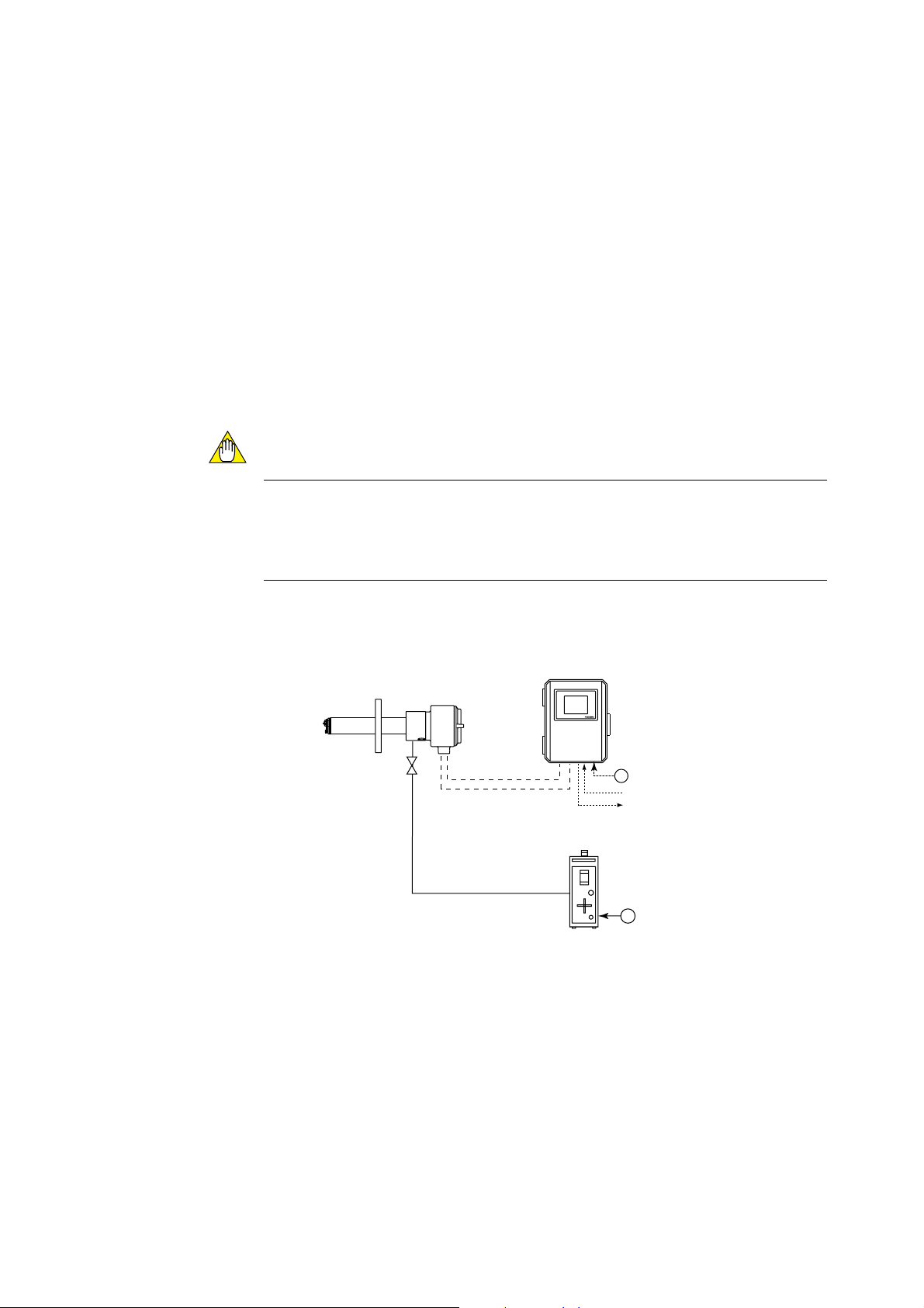
1.1.1 System 1
This is the simplest system consisting of a detector and a converter. This system can be
implemented for monitoring humidity in a production process such as food production.
No piping is required for the reference gas (air) which is fed in at the installation site.
The handy ZO21S standard gas unit is used for calibration.
Zero gas from this unit and span gas (air) is sent to the detector through a tube which is
connected during calibration.
CAUTION
• A needle (stop) valve should be connected to the calibration gas inlet of the detector.
The valve should be fully closed unless calibration is in progress.
• As this system uses ambient air for the reference gas, measuring accuracy will be
affected by the installation location.
Separate type Zirconia
High Temperature Humidity Analyzer,
Model ZR22G Detector
Stop valve
Signal
(6-core shield cable)
Heater (2-core)
Calibration gas
Figure 1.1
Model ZR402G Converter
EXA
ZR402G
100 to 240 V AC
,
Contact input
Analog outout, contact output
Digital output (HART)
Model ZO21S Standard gas unit
,
F1.1E.EPS
1-2
IM 11M12A01-03E
Page 16
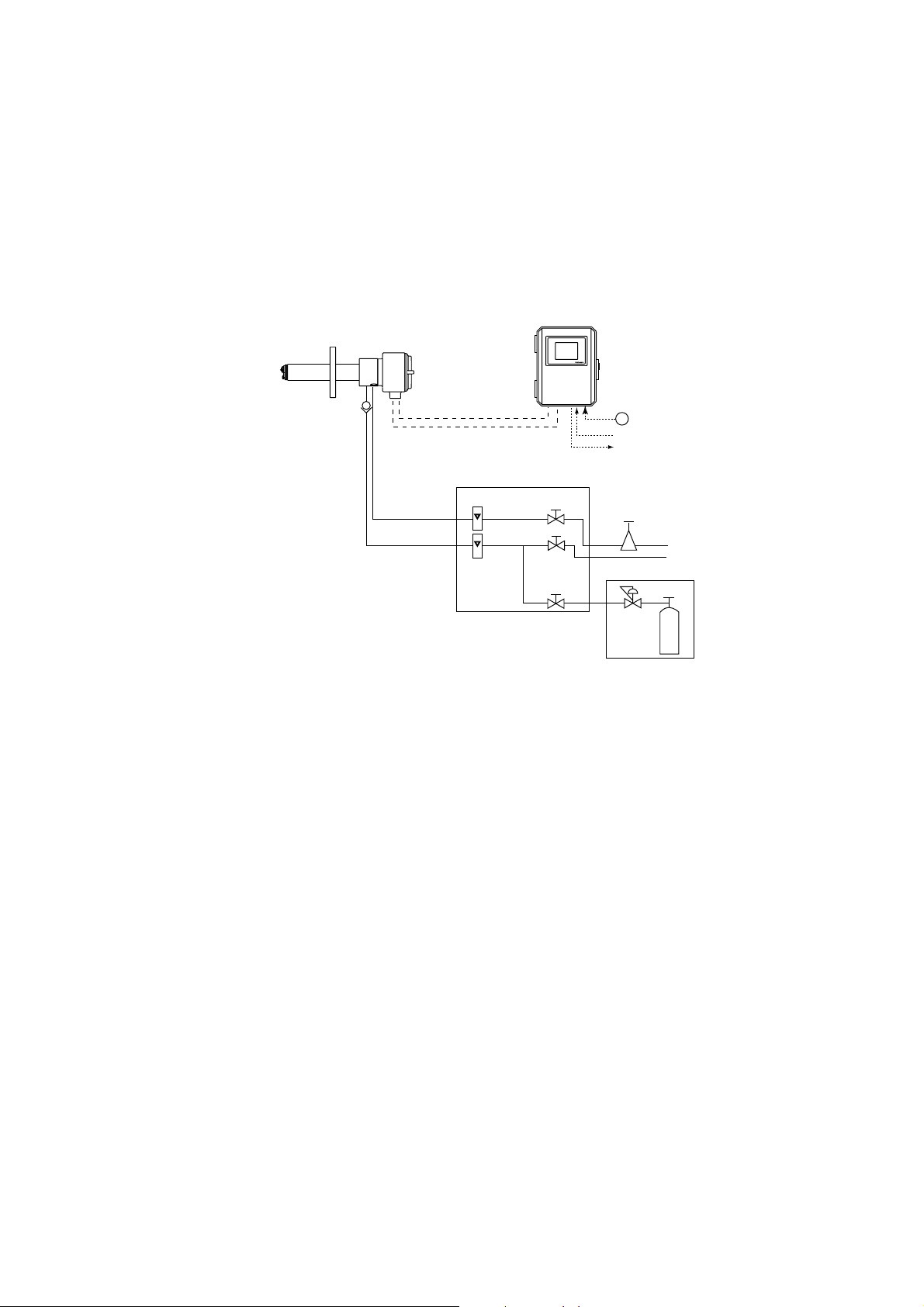
1.1.2 System 2
1. Overview
This system is for accurate monitoring and controlling humidity when the installation
environment is polluted with gases other than the air. Instrument air (clean and dry air
of oxygen concentration 21%) is used for the reference gas and the span gas for calibration. Zero gas is fed in from a cylinder during calibration. The gas flow is controlled by
the ZA8F flow setting unit (for manual valve operation).
Separate type Zirconia
High Temperature Humidity Analyzer,
Model ZR22G Detector
Check valve
or Stop valve
Calibration gas
Signal
(6-core shield cable)
Heater (2-core)
Reference
gas
Model ZA8F flow setting unit
Figure1.2
Model ZR402G Converter
Flowmeter
Needle
EXA
ZR402G
valve
100 to 240 V AC
,
Contact input
Analog outout, contact output
Digital output (HART)
Air Set
Instrument air
Span gas (Same as Zero gas
calibration unit)
Calibration gas pressure regulator
Calibration gas
unit case
Zero gas cylinder
F1.2E.EPS
IM 11M12A01-03E
1-3
Page 17
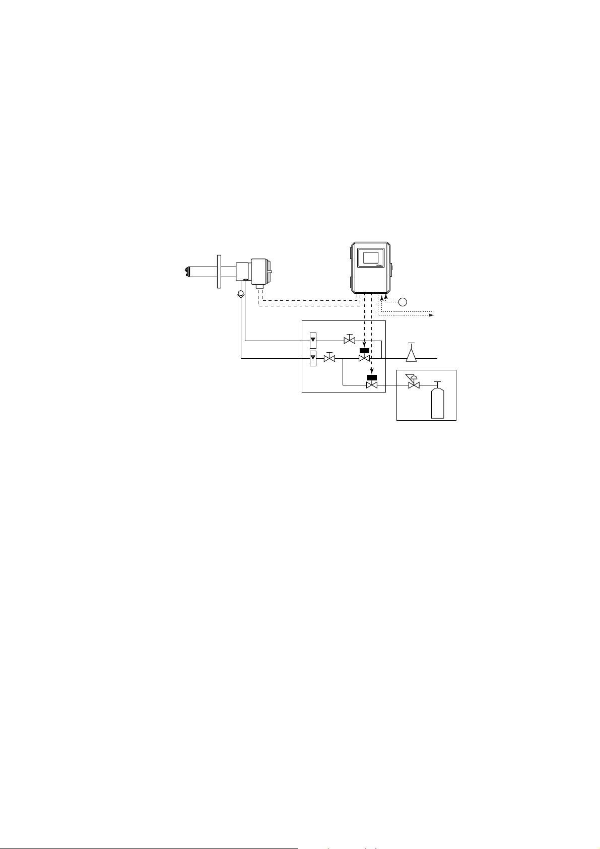
1.1.3 System 3
This system is for accurate monitoring and controlling of humidity. Instrument air
(clean and dry air) is used for the reference gas and the span gas for calibration. Zero
gas is fed in from a cylinder during calibration. The calibration gas flow is controlled
automatically by the ZR40H automatic calibration unit.
This system is similar to system 2, except that the calibration gas flow is automated
using the ZR40H automatic calibration unit.
Separate type Zirconia
High Temperature Humidity Analyzer,
Model ZR22G Detector
Check valve
*2
Reference gas
Calibration gas
Signal
(6-core shield cable)
Heater (2-core shield cable)
*1
Model ZR40H Auto-Calibration unit
Flowmeter
Model ZR402G Converter
EXA
ZR402G
,
Needle
vaive
Air Set
*3
100 to 240 V AC
Contact input
Analog output, contact output
Digital output (HART)
lnstrument air
Calibration gas pressure regulator
Calibration gas
unit case
Zero gas cylinder
F1.3E.EPS
Figure1.3
*1 Shield cable : Use shielded signal cables, and connect the shield to the FG terminal
of the converter.
*2 Select the desired probe from the Probe Configuration table on page 1-5
1-4
*3 100% N2 gas cannot be used as the zero gas. Use approximately 1% of O2 gas (N2 based).
IM 11M12A01-03E
Page 18
1.2 < EXAxtZR > System Components
1.2.1 System Components
Model or Part No. Product Name System 1 System 2 System 3
ZR22G Detector, Separate-type High-temperature
Humidity Analyzer, Detector
ZR402G Converter, Separate-type High-temperature
Humidity Analyzer, Converter
ZH21B Dust protector
ZO21S Standard gas unit
ZA8F Flow setting unit (for manual calibration)
ZR40H Automatic calibration unit (for separate type)
L9852CB/G7016XH Stop valve
K9292DN/K9292DS Check valve
K9473XH/K9473XJ, Air set
G7004XF/K9473XG
G7001ZC Zero gas cylinder
G7013XF/G7014XF Pressure regulator for gas cylinder
E7044KF Case assembly for calibration-gas cylinder
ZR22A Heater Assembly
(Spare parts for Model ZR22G)
d : The essential products for the system
s : Selected depending on your applications
(d) : Select either
1. Overview
Separate type
d d d
d d d
s s s
d
d
d
d (d)
(d) d
d d
d d
d d
d d
s s s
T1.1E.EPS
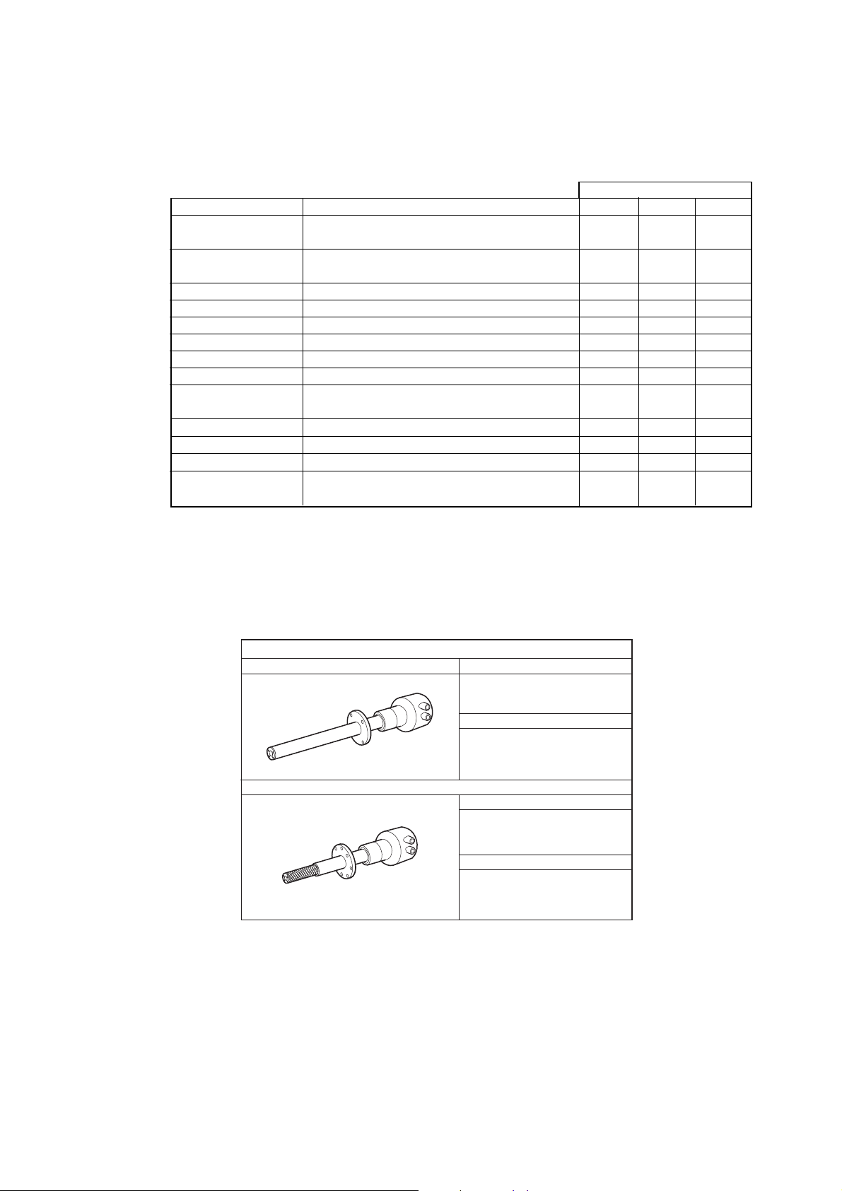
1.2.2 Detectors and Accessories
dGeneral-use Detector (sample gas temperature: 0 to 7008C)
Standard detector Model
ZR22G
Mounting angle
The probe insertion length: 0.4 to 2m
Vertical to horizontal
The probe insertion length: 2.5 to 3m
Vertical
Detector with dust protector
Model
ZR22G-040
and
ZH21B
Mounting angle
Vertical to horizontal
(The probe insertion length: 0.4m)
F1.4E.EPS
IM 11M12A01-03E
1-5
Page 19

Page 20

2. Specifications
This chapter describes the specifications for the following:
ZR22G General-use separate-type detector (See Section 2.2.1)
ZH21B Dust protector (See Section 2.2.2)
ZR402G Separate-type converter (See Section 2.3)
ZA8F Flow setting unit (See Section 2.4.1)
ZR40H Automatic calibration unit(See Section 2.4.2)
ZO21S Standard gas unit(See Section 2.5)
2.1 General Specifications
2.1.1 Standard Specifications
High Temperature Humidity Analyzer
Oxygen concentration in mixed gas which consists of water vapor and air is proportional
to the volume rate of air, so the volume rate of water vapor can be calculated by the
oxygen concentration.
2. Specifications
Measured Object:Water vapor (in vol%) in mixed gases (air and water vapor)
Measured System: Zirconia system
Measured Range: 0.01 to 100 vol% O2, 0 to 100 vol% H2O or 0 to 1.000 kg/kg
Output Signal: 4 to 20 mA DC (maximum load resistance 550V) Oxygen concentration;
Any setting in the range of 0 to 5 through 0 to 100 vol%O2 (in 1
vol% O2), or partial range.
Moisture quantity: 0 to 25 through 0 to 100 vol% H2O (in 1 vol% H2O), or partial
range.
Mixture ratio 0 to 0.2 through 0 to 1.000 kg/kg (in 0.001 kg/kg), or
partial range.
Digital Communication (HART): 250 to 550V, depending on quantity of field devices
connected to the loop (multi-drop mode).
(Note) HART is a registered trademark of the HART Communication
Foundation.
Display Range: Oxygen concentration; 0 to100 vol% O2 , Moisture quantity; 0 to 100
vol% H2O
Mixture ratio; 0 to 1 kg/kg
Relative humidity; 0 to 100 %RH
Dew point; -40 to 3708 C
(Note) Those values are calculated by temperature and absolute
pressure. Then accurate temperature and pressure value must be
input to the converter.
Warm-up Time: Approx. 20 min.
(Note) These characteristics are calculated by oxygen concentration
measured in air which include water vapor.
IM 11M12A01-03E
2-1
Page 21

Repeatability: (Note1)
61 vol% H2O (sample gas pressure 2 kPa or less)
Linearity: (Excluding standard gas tolerance)
(Note1)
(Use oxygen of known concentration (in the measuring range) as the
zero and span calibration gas.)
62 vol% H2O; (Sample gas pressure: within 60.49 kPa)
63 vol% H2O; (Sample gas pressure: 2 kPa or less)
Drift: (Excluding the first two weeks in use)
(Note1)
both zero and span 63 vol% H2O/month
Response Time: Response of 90 % within 5 seconds. (Measured after gas is introduced
from calibration-gas inlet and analog output starts changing.)
(Note1) These tolerances do not apply to the pressure compensated
version, or where natural convection is used for the reference air.
2-2
IM 11M12A01-03E
Page 22

2.2 General-use Separate-type Detector and Related Equipment
The “Detector with dust protector” consists of ZR22G general-use separate-type detector
and ZH21B dust protector (refer to Section 2.2.2).
2.2.1 ZR22G General-use Separate-type Detector
Sample Gas Temperature: 0 to 7008 C (Probe only)
It is necessary to mount the cell using Inconel cell-bolts when the
temperature is 6008 C or greater.
Sample Gas Pressure: -5 to +20 kPa (When the pressure in the process exceeds 3kPa,
it is recommended that you compensate the pressure. When the pressure
in the process exceeds 5kPa, you must perform pressure compensation.)
No pressure fluctuation in the process should be allowed.
Probe Length: 0.4, 0.7, 1.0, 1.5, 2.0, 2.5, 3.0 m
Probe Material: SUS 316 (JIS)
Ambient Temperature: -20 to +1508 C
Reference Air System: Natural Convection, Instrument Air
Instrument Air System (excluding Natural Convection):
Pressure; 200 kPa + the pressure inside the dryer, (It is recommended to
use air which has been dehumidified by cooling to dewpoint -208 C or
less, and with dust or oil mist removed.)
Consumption; Approx. 1Nl/min
Note: When the detector is used in conjunction with a check valve and a
ZA8F Flow Setting Unit, the maximum pressure of sample gas is 150
kPa. When with a check valve and a ZR40H Auto Calibration Unit, it is
200 kPa. If the pressure of your sample gas exceeds these limits, consult
with Yokogawa.
Material in Contact with Gas: SUS 316 (JIS), Zirconia, SUS 304 (JIS) (flange),
Hastelloy B, (Inconel 600, 601)
Construction: Heater and thermocouple replaceable construction. Non explosion-proof
JIS C0920 / equivalent to IP44D. Equivalent to NEMA 4X / IP66
(Achieved when the cable entry is completely sealed with a cable
gland in the recirculation pressure compensated version.)
2. Specifications
IM 11M12A01-03E
Terminal Box Case: Material; Aluminium alloy
Terminal Box Paint Color:
Case; Mint green (Munsell 5.6BG3.3/2.9)
Cover; Mint green (Munsell 5.6BG3.3/2.9)
Finish: Polyurethane corrosion-resistant coating
Gas Connection: Rc 1/4 or 1/4 FNPT
Wiring Connection: G1/2, Pg13.5, M20 by 1.5mm, 1/2 NPT
Installation: Flange mounting
2-3
Page 23

Probe Mounting Angle: Horizontal to vertically downward.
When the probe insertion length is 2 m or less, installing at angles from
horizontal to vertically downward is available.
When the probe insertion length exceeds 2.5 m, mount vertically down-
ward (within 658 ) and use a probe protector.
Weight:
Insertion length of 0.4 m: approx. 6 kg (JIS 5K 65) / approx. 11 kg (ANSI 150 4)
Insertion length of 1.0 m: approx. 8 kg (JIS 5K 65) / approx. 13 kg (ANSI 150 4)
Insertion length of 1.5 m: approx. 10 kg (JIS 5K 65) / approx. 15 kg (ANSI 150 4)
Insertion length of 2.0 m: approx. 12 kg (JIS 5K 65) / approx. 17 kg (ANSI 150 4)
Insertion length of 3.0 m: approx. 15 kg (JIS 5K 65) / approx. 20 kg (ANSI 150 4)
2-4
IM 11M12A01-03E
Page 24
2. Specifications
Model and Codes
Model
ZR22G
Suffix code
Option
code
Description
Separate type Detector of Zirconia High Temperature Humidity
[ Style : S2 ]
Analyzer
Length
-040
-070
-100
-150
-200
-250
-300
Wetted material
-S
-C
Flange
(*2)
-A
-B
-C
-E
-F
-G
-K
-L
-M
-P
-R
-S
-W
Reference air
-C
-E
-P
Gas Thread
-T
Connection box thred
-P
-G
-M
-T
-Q
Instruction manual
-J
-E
-A
Options
/D
/C
/CV
/SV
/PT
-R
/SCT
0.4 m
0.7 m
1.0 m
1.5 m
2.0 m
2.5 m (*1)
3.0 m (*1)
SUS316
Stainless steel with lnconel calibration gas tube
ANSI Class 150 2 RF SUS304
ANSI Class 150 3 RF SUS304
ANSI Class 150 4 RF SUS304
DIN PN10 DN50 SUS304
DIN PN10 DN80 SUS304
DIN PN10 DN100 SUS304
JIS 5K 65 FF SUS304
JIS 10K 65 FF SUS304
JIS 10K 80 FF SUS304
JIS 10K 100 FF SUS304
JPI Class 150 4 RF SUS304
JPI Class 150 3 RF SUS304
Westinghouse
Natural convection
External connection (Instrument air) (*8)
Pressure Compensation (*8)
Rc 1/4
1/4 NPT(F)
G1/2
Pg13.5
M20 x1.5 mm
1/2NPT
Quick connect (*6)
Japanese
English
Always-A
DERAKANE coating (*7)
Inconel bolt (*3)
Check valve (*4)
Stop valve (*4)
Stainless steel tag plate (*5)
Printed tag plate (*5)
*1 When installing horizontally the probe whose insertion length is 2.5 meters or more, use the Probe Protector. Be sure to specify
ZO21R-L-hhh-h. Specify the flange suffix code either -C or -K.
*2 The thickness of the flange depends on its dimensions.
*3 Inconel probe bolts and U shape pipe for calibration are used. Use this option for high temperature use (ranging from 600 to 700 8C).
*4 Specify either /CV or /SV option code.
*5 Specify either /SCT or /PT option code.
*6 Not waterproof, protect from rain.Operating maximum temperature is 80 8C. Available only in the U.S.
*7 Available only in the U.S. DERAKANE is a registered trademark of the Dow Chemical Company.
*8 Piping for reference air must be installed to supply reference air constantly at a specified flow rate.
T2.1E.EPS
IM 11M12A01-03E
2-5
Page 25
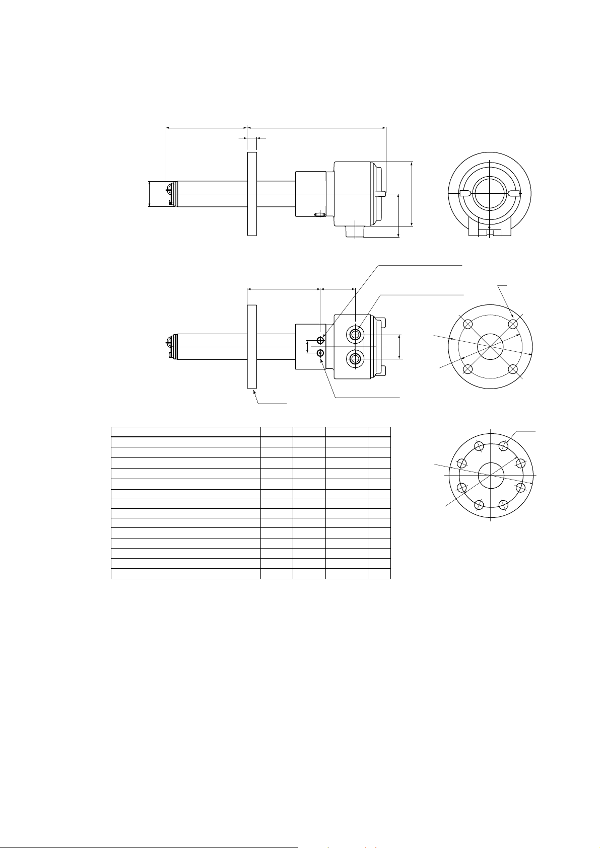
EXTERNAL DIMENSIONS
Model ZR22G Detectors Separate type Zirconia High Temperature Humidity Analyzer
[50.8
L=0.15, 0.4, 0.7, 1.0,
1.5, 2.0, 2.5, 3.0 (m)
L
t
Flange
283 to 292
155 to 163 69
25
85
Rc1/4 or 1/4NPT
Reference air inlet
2-G1/2,2-1/2NPT etc.
Cable connection port
48
Rc1/4 or 1/4NPT
Calibration gas inlet
[124
C
[A
[B
Flange
Flange
ANSI Class 150 2 RF SUS304
ANSI Class 150 3 RF SUS304
ANSI Class 150 4 RF SUS304
DIN PN10 DN50 SUS304
DIN PN10 DN80 SUS304
DIN PN10 DN100 SUS304
JIS 5K 65 FF SUS304
JIS 10K 65 FF SUS304
JIS 10K 80 FF SUS304
JIS 10K 100 FF SUS304
JIS 5K 32 FF SUS304
JPI Class 150 4 RF SUS304
JPI Class 150 3 RF SUS304
Westinghouse
AB C
152.4
190.5
228.6
165
200
220
155
175
185
210
115
229
190
155
120.6
152.4
190.5
125
160
180
130
140
150
175
90
190.5
152.4
127
4 - [19
4 - [19
8 - [19
4 - [18
8 - [18
8 - [18
4 - [15
4 - [19
8 - [19
8 - [19
4 - [15
8 - [19
4 - [19
4 - [11.5
19
24
24
18
20
20
14
18
18
18
24
24
14
t
[A
[B
Flange
5
C
F07_01.EPS
2-6
IM 11M12A01-03E
Page 26
2. Specifications
Model ZR22G...-P Detectors(with pressure compensation), Separate type Zirconia High Temperature
Humidity Analyzer, Detectors
L
f50.8
L=0.15, 0.4, 0.7, 1.0,
1.5, 2.0, 2.5, 3.0 (m)
L
Reference gas outlet
Flange
ANSI Class 150 2 RF SUS304
ANSI Class 150 3 RF SUS304
ANSI Class 150 4 RF SUS304
DIN PN10 DN50 SUS304
DIN PN10 DN80 SUS304
DIN PN10 DN100 SUS304
JIS 5K 65 FF SUS304
JIS 10K 65 FF SUS304
JIS 10K 80 FF SUS304
JIS 10K 100 FF SUS304
JPI Class 150 4 RF SUS304
JPI Class 150 3 RF SUS304
Westinghouse
Flange
t
303
156
t
25
PIPING
:B
PIPING : A
AB C
152.4
190.5
228.6
165
200
220
155
175
185
210
229
190
155
120.6
152.4
190.5
190.5
152.4
125
160
180
130
140
150
175
127
4 - [19
4 - [19
8 - [19
4 - [18
8 - [18
8 - [18
4 - [15
4 - [19
8 - [19
8 - [19
8 - [19
4 - [19
4 - [11.5
85
Rc1/4 or 1/4NPT
Reference air inlet
87
2-G1/2, 2-1/2NPT etc.
Cable connection port
48
Rc1/4 or 1/4NPT
Calibration gas inlet
Stop Valve
t
PIPING
19
24
24
18
20
20
14
18
18
18
24
24
14
A
B
B
A
B
B
A
A
B
B
B
B
A
f124
C
[A
[B
Flange
C
[A
[B
Flange
F07_02.EPS
IM 11M12A01-03E
2-7
Page 27
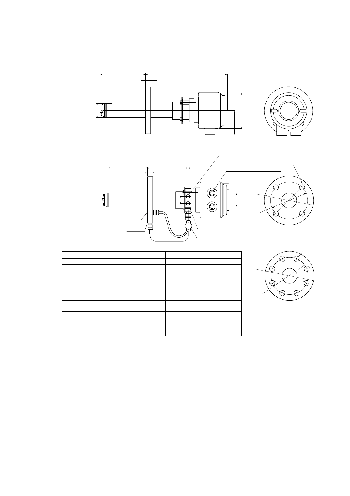
2.2.2 ZH21B Dust Protector
This protector is designed to protect the probe output from dust agitation (i.e., to prevent
combustible materials from entering the probe cell where humidity measurements are
made) in a dusty environment.
d Standard Specification
Insertion length: 0.428m
Flange: JIS 5K 80 FF SUS304 or ANSI Class 150 4 FF SUS304 (However,
Material: SUS 316(JIS), SUS 304(JIS) (flange)
Weight: Approximately 6kg (JIS), approximately 8.5kg (ANSI)
Mounting: Mounted on the probe or process flange with bolts and associated
flange thickness is different)
nuts and washers.
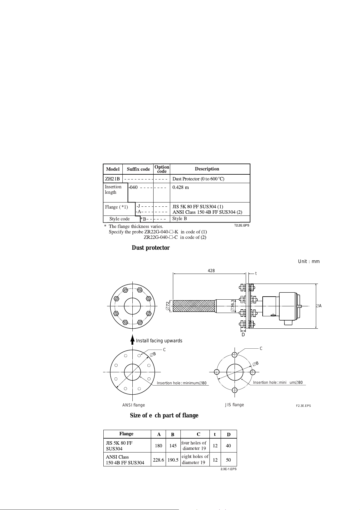
Model Suffix code
ZH21B
Insertion
length
Flange ( *1)
Style code
* The flange thickness varies.
Specify the probe ZR22G-040-h-K in code of (1)
-040 0.428 m
-A
Option
code
Dust Protector (0 to 6008C)
-J
*B
ZR22G-040-h-C in code of (2)
JIS 5K 80 FF SUS304 (1)
ANSI Class 150 4B FF SUS304 (2)
Style B
Dust protector
72
[
Install facing upwards
C
[B
Description
428
T2.2E.EPS
76.3
[
D
[B
Unit ; mm
t
[
A
C
2-8
Insertion hole;minimum[80
ANSI flange
Size of each part of flange
Flange
JIS 5K 80 FF
SUS304
ANSI Class
150 4B FF SUS304
A
180
228.6
B
145
190.5
four holes of
diameter 19
eight holes of
diameter 19
Ct
12
12
2.3E-1.EPS
JIS flange
D
40
50
Insertion hole;minimum[80
F2.3E.EPS
IM 11M12A01-03E
Page 28

2.3 ZR402G Separate-type Converter
2.3.1 Standard Specifications
Operated using an LCD touchscreen on the converter.
Display: LCD display of size 320 by 240 dot with touchscreen.
Output Signal: 4 to 20 mA DC, two points (maximum load resistance 550 V)
Contact Output Signal: four points (one is fail-safe, normally open)
Contact Input: two points
Analog Input: one point (thermal input 4-20 mA)
Auto-calibration Output: Two points (for dedicated auto-calibration unit)
Ambient Temperature: -20 to +558C
Storage Temperature: -30 to +708C
Humidity Ambient: 0 to 95%RH (Non-condensing)
Installation Altitude: 2000 m or less
Category based on IEC 1010: II (Note)
2. Specifications
Pollution degree based on IEC 1010: 2 (Note)
Note: Installation category, called over-voltage category, specifies impulse withstanding voltage. Category II is for electrical equipment.
Pollution degree indicates the degree of existence of solid, liquid, gas or other
inclusions which may reduce breakdown voltage. Degree 2 is the normal indoor
environment.
Power Supply Voltage: Ratings; 100 to 240 V AC
Acceptable range; 85 to 264 V AC
Power Supply Frequency: Ratings; 50/60 Hz Acceptable range; 45 to 66 Hz
Power Consumption: Max. 300 W, approx. 100 W for ordinary use.
Safety and EMC conforming standards
Safety: EN61010-1
CSA C22.2 No.61010-1
UL61010-1
EMC: EN 61326 Class A
EN 55011 Class A Group 1
EN 61000-3-2
AS/NZS CISPR 11
Maximum Distance between Probe and Converter: Conductor two-way resistance must
be 10 V or less (when a 1.25 mm2 cable or equivalent is used, 300 m or less.)
Construction: Outdoor installation, equivalent to NEMA 4 (with conduit holes
completely sealed with a plastic cable gland optional)
Wiring Connection: G1/2, Pg13.5, M20 by 1.5 mm, 1/2 NPT, eight holes
Installation: Panel, wall or 2B pipe mounting
Case: Aluminum alloy
Paint Color: Door: Sliver gray (Munsell 3.2PB7.4/1.2)
Case: Sliver gray (Munsell 3.2PB7.4/1.2)
Finish: Polyurethane corrosion-resistant coating
Weight: Approx. 6 kg
IM 11M12A01-03E
2-9
Page 29

2.3.2 Function
Display Functions:
Value Display; Displays values of the measured Oxygen concentration,
moisture quantity, mixture ratio etc.
Graph Display; Displays trends of measured oxygen concentration moisture
quantity, mixture ratio etc.
Data Display; Displays various useful data for maintenance, such as cell
temperature, reference junction temperature, maximum/
minimum moisture quantity and the like.
Status Messages; Indicates an alarm or error occurrence with flashing of the corre-
sponding icon. Indicates status such as warming-up, calibrating,
or the like by symbols.
Alarm, Error Display: Displays alarms such as “Abnormal moisture quantity” or
errors such as “Abnormal cell e.m.f.” when any such status
occurs.
Calibration Functions:
Auto-Calibration; Requires the Auto-calibration Unit. It calibrates automatically at
specified intervals.
Semi-auto Calibration; Requires the Auto-calibration Unit. Input calibration direction
on the touchpanel or contact, then it calibrates automatically
afterwards.
Manual Calibration; Calibration with opening/closing the valve of calibration gas in
operation interactively with an LCD panel.
Blowback Function:
Output through the contact at a set period and time. Auto/semi-auto
selectable.
Maintenance Functions:
Can update data settings during daily operation and checking.
Display data settings, calibration data settings, blowback data settings,
current output loop check, input/output contact check.
Setup Functions:
Initial settings suit for the plant conditions when installing the con
verter. Equipment settings, current output data settings, alarm data
settings, contact data settings, other settings.
Self-diagnosis:
This function diagnoses conditions of the converter or the probe and
indicates when any abnormal condition occurs.
Password Functions:
Enter your password to operate the analyzer excepting data display.
Individual passwords can be set for maintenance and setup.
2-10
IM 11M12A01-03E
Page 30

Display and setting content:
Measuring-related items: Oxygen concentration (vol% O2), moisture quantity(vol% H2O),
Display Related Items: Oxygen concentration (vol% O2), Moisture quantity (vol% H2O),
Calibration Setting Items: Span gas concentration (vol% O2), zero gas concentration
Output Related Items: Analog output/output mode selection, value conditions when
Alarm Related Items: Oxygen concentration high-alarm/high-high alarm limit values
2. Specifications
mixture ratio (kg/kg), relative humidity (%RH) and dew point (8 C)
mixture ratio (kg/kg), relative humidity (%RH), dew point (8 C), cell temperature (8 C), thermocouple reference junction temperature (8 C), maximum/
minimum/average oxygen concentration (vol% O2), maxi-mum/minimum/
average moisture quantity (vol% H2O), maximum/minimum/average mixture
ratio (kg/kg), cell e.m.f. (mV), output 1, 2 current (mA), cell response time
(seconds), cell internal resistance (V), cell condition (in four grades), heater ontime ratio (%), calibration history (ten times), time (year/month/day/hour/
minute)
(vol% O2), calibration mode (auto, semi-auto, manual), calibration type and
method (zero-span calibration, zero calibration only, span calibration only),
stabilization time (min.sec), calibration time (min.sec), calibration period (day/
hour), starting time (year/month/day/hour/minute)
warming-up/maintenance/calibrating(or blowback)/abnormal, oxygen concentration at 4mA/20mA (vol% O2), moisture quantity at 4mA/20mA (vol% H2O),
mixture ratio at 4mA/20mA (kg/kg), time constant.
(vol% O2), Oxygen concentration low-alarm/low-low alarm limit values (vol%
O2), moisture quantity high-alarm/high-high alarm limit values (vol% H2O),
moisture quantity low-alarm/low-low alarm limit values (vol% H2O), mixture
ratio high-alarm/high-high alarm limit value (kg/kg), mixture ratio low-alarm/
low-low alarm limit values (kg/kg), oxygen concentration alarm hysteresis
(vol% O2), moisture quantity alarm hysteresis (vol% H2O), mixture ratio alarm
hysteresis (kg/kg), oxygen concentration/moisture quantity/mixture ratio alarm
detection, alarm delay (seconds).
Contact Related Items: Selection of contact input 1 and 2, selection of contact output 1
to 3 (abnormal, high-high alarm, high-alarm, low-alarm, low-low alarm,
maintenance, calibrating, range switching, warming-up, calibration-gas pressure-decrease, temperature high-alarm, blow back, unburnt gas detected)
Converter Output: Two points mA analog output (4 to 20 mA DC (maximum load
resistance of 550V) and one of two mA digital output points (HART) (minimum load resistance of 250V).
Range: any setting between 0 to 5 through 0 to 100 vol% O2, 0 to 25 through 0 to 100
vol% H2O, 0 to 0.200 through 0 to 1.000 kg/kg or partial range is available.
For the log output, the minimum range values are fixed at 0.1 vol% O2 for the
oxygen concentration, 0.1 vol% H2O for the moisture quantity, and 0.01 kg/kg
for the mixture ratio.
4 to 20 mA DC linear or log can be selected.
Input/output isolation provided.
Output damping 0-255 (sec.)
Can select hold or non-hold, and set preset value for hold.
IM 11M12A01-03E
2-11
Page 31

Contact Output: Four points, contact capacity 30V DC 3A, 250V AC 3A
(resistive load).
Three of the output points can be selected to either normally energized or
normally de-energized status.
Delayed functions (0 to 255 seconds) and hysteresis function (0 to 9.9 vol% O
can be added to high/low-alarms.
The following functions are programmable for contact outputs.
(1) Abnormal, (2) High-high alarm, (3) High-alarm, (4) Low-low alarm, (5)
Low-alarm, (6) Maintenance, (7) Calibration, (8) Range switching answer-back,
(9) Warm-up, (10) Calibration-gas pressure decrease (answerback of contact
input), (11) Temperature high-alarm, (12) Blowback start, (13) Flameout gas
detection (answerback of contact input), (14) Calibration coefficient alarm, (15)
Startup power stabilization timeout alarm
Contact output 4 is set to normally operated, and fixed error status.
Converter Input: Thermal input one point (4 to 20 mA DC)
Contact Input: Two points, voltage-free contact inputs
The following functions are programmable for contact inputs:
(1) Calibration-gas pressure decrease alarm, (2) Range switching (switched
range is fixed), (3) External calibration start, (4) Process alarm (if this signal is
received, the heater power turns off), (5) Blowback start
Contact capacity: Off-state leakage current: 3 mA or less
Self-diagnosis: cell abnormal , cell temperature abnormal (low/high), calibration
abnormal, A/D converter defective, digital circuit defective
2
Calibration:Method; zero/span calibration
Calibration mode; automatic, semi-automatic and manual (All are operated
interactively with an LCD touchpanel). Either zero or span can be skipped.
Zero calibration-gas concentration setting range: 0.3 to 100 vol% O2 (minimum
in 0.01 vol%).
Span calibration-gas concentration setting range: 4.5 to 100 vol% O2 (minimum
in 0.01 vol%).
Use nitrogen-based mixed gas containing about 10% of oxygen for standard
zero-gas, and 80 to 100 % of oxygen for standard span-gas.
Calibration period; date/time setting: maximum 255 days
2-12
IM 11M12A01-03E
Page 32

d Model and Suffix Codes
Model
Suffix code
ZR402G
Converter
thread
-P
-G
-M
-T
Display
-J
-E
-G
-F
Instruction manual
Options
Tag plates
*1 Specify either /SCT or /PT option code.
*2 Sun shield hood is still effective even if scratched.
*3 Be sure to use the equipment with the option code /HS.
Option
code
Description
Separate type Zirconia High Temperature
Humidity Analyzer, Converter
G1/2
Pg13.5
M20x1.5 mm
1/2NPT
Japanese
English
German
French
-J
-E
-A
/HS
/H
/SCT
/PT
Japanese
English
Always -A
Set for Humidity Analyzer (*3)
Hood (*2)
Stainless steel tag plate (*1)
Printed tag plate (*1)
2. Specifications
T2.4E.EPS
IM 11M12A01-03E
2-13
Page 33

280
d External Dimensions
Unit ;mm
1 to 6 (Panel Thickness)
2-inch mounting pipe
EXA
ZR402G
4 - f 6 holes
for Wall mounting
126.5
100
120.2
8
228
10
57.3
136.3
36
54.7
(1/2NPT)
111
40
40 40
8-G1/2, 8-1/2NPT etc
(Wiring connection)
2346
38 2414 38
( for wall mounting)
190
Wall mounting
d Accessories
Item
Fuse
Bracket for mounting
Screw for Bracket
126.5
Part. No.
A1113EF
F9554AL
F9123GF
4 - f 6 holes
Qty
1
1
1
4-R8 to R10
or
4-C5 to C8
+2
183
0
Panel Cut-out
Description
3.15A
for pipe mounting, panel mounting
or wall mounting
+2
0
274
F2.5E.EPS
2-14
IM 11M12A01-03E
Page 34

2. Specifications
d Hood (Option / H)
64
243
6362
12355
ZR402G
64
251.5
6263
3994.5
205.5
64
155.5
Unit ;mm
63
Hood material : Aluminum
IM 11M12A01-03E
2-15
Page 35

2.4 ZA8F Flow Setting Unit and ZR40H Automatic Calibration Unit
2.4.1 ZA8F Flow Setting Unit
This flow setting unit is applied to the reference gas and the calibration gas in a system
configuration (System 2).
This unit consists of a flow meter and flow control valves to control the flow of calibration gas and reference air.
• Standard Specifications
FIowmeter: Calibration gas; 0.1 to 1.0 l/min. Reference air; 0.1 to 1.0 l/min.
Construction: Dust-proof and rainproof construction
Case Material: SPCC (Cold rolled steel sheet)
Painting: Baked epoxy resin, Dark-green (Munsell 2.0 GY 3.1/0.5 or equivalent)
Pipe Connections: Rc1/4 or 1/4FNPT
Reference Air pressure: Clean air supply of measured gas pressure plus approx. 50 kPa G
(or measured gas pressure plus approx. 150kPa G when a check valve is used)
pressure at inlet of the auto-calibration unit (Maximum 300 kPaG).
Air Consumption: Approx. 1.5 l/min
Weight: Approx. 2kg
Calibration gas (zero gas,span gas) flow : 0.7 l/min (at calibration time only)
d Model and Codes
Model Suffix code Option code Description
ZA8F
Joint
Style code
-J
-A
*B
Flow setting unit
Rc 1/4
With 1/4" NPT adapter
Style A
T2.5E.EPS
2-16
IM 11M12A01-03E
Page 36

d External Dimensions
2. Specifications
Reference air outlet
f6 hole
7
235.8
222.8
Zero gas outlet
REFERENCE CHECK
Span gas inlet
180
140
REFERENCE
SRAN
Unit: mm
ZERO
Zero gas inlet
268
70
ZERO
GAS IN
35
20 2035 35
35
CHECK
OUT
Flow
meter
SPAN
GAS IN
4-Rc1/4
Piping connection
port
35
Instrument air inlet
REF
OUT
Flow
meter
AIR IN
IM 11M12A01-03E
Airset
Instrument air
Approx 1.5 l/min.
Air pressure:
without check valve ; measured gas pressure 1 approx.50 kPaG
with check valve ; measured gas pressure 1 approx.150 kPaG
F2.6E.EPS
2-17
Page 37

2.4.2 ZR40H Automatic Calibration Unit
This automatic calibration unit is applied to supply specified flow of reference gas and
calibration gas during automatic calibration to the detector in a system configuration
(System 3).
• Specifications
Used when auto calibration is required for the separate type and instrument air is
provided. The solenoid valves are provided as standard.
Construction: Dust-proof and rainproof construction:
NEMA4X/IP67 solenoid valve only (excluding flowmeter)
Mounting: 2-inch pipe or wall mounting, no vibration
Materials: Body; Aluminum alloy, Piping; SUS316 (JIS), SUS304 (JIS), Flowmeter; MA
Finish: Polyurethane corrosion-resistance coating, mint green (Munse11 5.6BG3.3/2.9)
Piping Connection: Refer to Model and Suffix Codes
Power Supply: 24V DC (from ZR402G), Power consumption; Approx. 1.3W
Reference Air Pressure: Sample gas pressure plus Approx. 150 kPa (690 kPa max.),
(Pressure at inlet of auto-calibration unit)
(acrylic resin), Bracket ; sus304 (JIS)
Air Consumption: Approx. 1.5 l/min
Weight: Approx. 3.5 kg
Ambient Temperature: -20 to +558 C, no condensation or freezing
Ambient Humidity: 0 to 95% RH
Storage Temperature: -30 to +658 C
d Model and Codes
Model Suffix code Option code Description
ZR40H
Gas piping connection
Wiring connection
-
-R
-T
-P
-G
-M
-T
-A
Automatic calibration unit for ZR402G
Rc 1/4
1/4" NPT
Pipe connection (G1/2)
Pg 13.5
20 mm (M20 x 1.5)
1/2 NPT
Always -A
T2.5-1E.EPS
2-18
IM 11M12A01-03E
Page 38

d External Dimensions
2B pipe mounting example
*1 with four M6 screws can wall-mount
54 71.526
41.2 41.2
Flowmeter
Setting Valve for
reference air
wiring inlet ; 2-G1/2,Pg13.5,M2031.5 or 1/2NPT(Female)
(wiring inlet is at same position on rear)
90 116.5
*1
4-
f
6.5
12223
250
140
2. Specifications
Unit : mm
49.5
OCK
Setting Valve for
calibration gas
calibration gas outlet
Rc1/4 or 1/4 NPT(Female)
Zero gas air inlet
Rc1/4 or 1/4 NPT(Female)
102 MAX58
42
26
3040 47.5 25
46 16
IM 11M12A01-03E
reference air outlet
Rc1/4 or 1/4 NPT(Female)
reference gas inlet
Rc1/4 or 1/4 NPT(Female)
F2.6-2E.EPS
2-19
Page 39

Piping
CHECK
OUT
flow
meter
REF
OUT
flow
meter
*2 *2
EV1 EV2
ZERO GAS IN
AIR IN
Instrument air Approx.
1.5 l/min.
*2 Needle valve is supplied as accessory with flow meter.
F2.6-3E.EPS
2-20
IM 11M12A01-03E
Page 40
2.5 ZO21S Standard Gas Unit
This is a handy unit to supply zero gas and span gas to the detector in a system configuration based on System 1. It is used in combination with the detector only during
calibration.
d Standard Specifications
Function: Portable unit for calibration gas supply consisting of span gas (air) pump, zero
gas cylinder with sealed inlet, flow rate checker and flow rate needle valve.
Sealed Zero Gas Cylinders (6 provided): E7050BA
Capacity: 1 l
Filled pressure: Approx. 686 kPa G (at 35 8 C)
Composition: 0.95 to 1.0 vo1% O2+N2 based
Power Supply: l00, 110, 115, 200, 220, 240 V AC6 10%, 50/60 Hz
Power Consumption: Max. 5 VA
Case Material: SPCC (Cold rolled steel sheet)
2. Specifications
Point: Epoxy resin, baked
Paint Color:
Mainframe; Munsell 2.0 GY3.1/0.5 equivalent
Cover; Munsell 2.8 GY6.4/0.9 equivalent
Piping: f 63f 4mm flexible tube connection
Span Gas: Internal pump draws in air from atmosphere, and feeds to detector.
Weight: Approx. 3 kg
p Non CE Mark.
d Model and Codes
Model
ZO21S
Power
supply
Panel
Style code
Suffix code Option code
-2
-3
-4
-5
-7
-8
-J
-E
*A
Description
Standard gas unit
200 V AC 50/60 Hz
220 V AC 50/60 Hz
240 V AC 50/60 Hz
100 V AC 50/60 Hz
110 V AC 50/60 Hz
115 V AC 50/60 Hz
Japanese version
English version
Style A
T2.6E.EPS
IM 11M12A01-03E
2-21
Page 41

d External Dimensions
1600
Zero gas cyilnder (6 cyilnder): E7050BA
354
Unit : mm
92
228
253
Flow checker
Span gas valve
Zero gas valve
Gas outlet
F2.7E.EPS
2.6 Other Equipment
2.6.1 Stop Valve (Part Number: L9852CB or G7016XH)
This valve is mounted on the calibration gas line in the system to allow for one-touch
calibration. This applies to the system configuration shown for system 1 in section 1.
Standard Specifications
Connection: Rc 1/4 or 1/4 FNPT
Material: SUS 316 (JIS)
Weight: Approx. 80 g
Part No.
L9852CB
G7016XH
Joint: RC 1/4, Material: SUS 316 (JIS)
Joint:
43
Description
1/4 NPT,
55
Material:
SUS 316 (JIS)
Unit: mm
T2.9E.EPS
2-22
Rc1/4 or 1/4NPT
40
(Full open length)
F15.EPS
IM 11M12A01-03E
Page 42
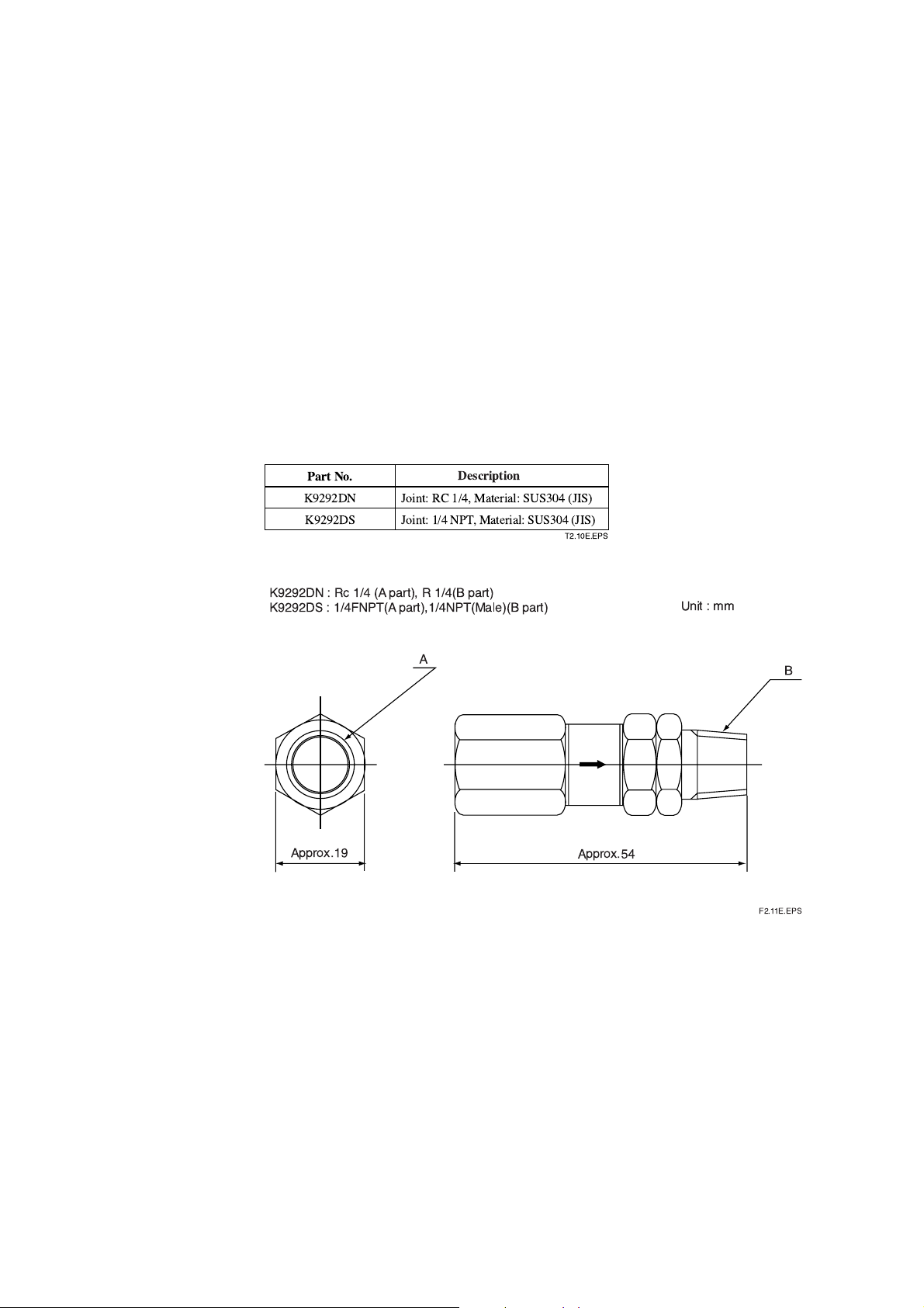
2.6.2 Check Valve (Part Number: K9292DN or K9292DS)
This valve is mounted on the calibration gas line (directly connected to the detector).
This is applied to a system based on the (System 2 and 3) system configuration.
This valve prevents the process gas from entering the calibration gas line. Although it
functions as a stop valve, operation is easier than a stop valve as it does not require
opening/closing at each calibration.
Screw a check valve into the calibration gas inlet of the detector instead of the stop
valve.
Standard Specifications
Connection: Rc1/4 or 1/4FNPT
Material: SUS304 (JIS)
Pressure: 70 kPa G or more,and 350 kPa G or less
Weight: Approx. 40 g
2. Specifications
1/4 NPT
A
Description
, Material:
SUS304
Part No.
K9292DN
K9292DS
K9292DN : Rc 1/4 (A part), R 1/4(B part)
K9292DS : 1/4FNPT(A part),1/4NPT(Male)(B part)
Approx.19
Joint: RC 1/4, Material: SUS304 (JIS)
Joint:
(JIS)
T2.10E.EPS
Unit : mm
B
Approx.54
F2.11E.EPS
IM 11M12A01-03E
2-23
Page 43

2.6.3 Air Set
Part Number: K9473XH or K9473XJ
This set is used to lower the pressure when instrument air is used as the reference and
span gases.
Standard Specifications
Primary Pressure: Max. 2 MPa G
Secondary Pressure: 0 to 0.25 MPa G
Connection: Rc1/4 or 1/4FNPT (includes joint adapter)
Weight: Approx.1 kg
Part No.
K9473XH
K9473XJ
(53.5)
(63)
Description
Joint: Rc 1/4, Material: Aluminum
Joint:
1/4
NPT (F) , Material: Body; Aluminum,
Dimensions in parentheses are approximate.
40
(116)
[54
Adapter; Zinc alloy
T2.11E.EPS
60
IN
69.5
42
8
Unit: mm
(43.5)
OUT
(135.5)
[48
2-24
18.5
28
7
Bracket Mounting Dimensions
K9473XH: Piping connection (IN: Primary side, OUT: Secondary side), Rc1/4
K9473XJ: Piping connection (IN: Primary side, OUT: Secondary side), 1/4NPT
IM 11M12A01-03E
Page 44

Part Number; G7004XF or K9473XG
Primary Pressure: Max. 1 MPa G
Secondary Pressure: 0.02 to 0.5 MPa G
Connection: Rc1/4 or 1/4 FNPT with joint adapter
2. Specifications
Part No.
G7004XF
K9473XG
Joint: Rc 1/4, Material: Zinc Alloy
Joint:
d External Dimensions
Panel cut dimensions
Horizontal
mounting
[15
22
+0.5
-0
2-2.2
Description
1/4
NPT (F) , Material: Body; Zinc Alloy,
Vertical
mounting
40
2-[6.5
max. 55
Adapter; SUS316
T2.13E.EPS
Unit : mm
View A
40
2-[6 screw depth 10
Panel (Horizontal
mounting)
Primary
[74
Secondary
88
Max. 210
Secondary
pressure
gauge
G7004XF: Rc 1/4
K9473XG: 1/4NPT connector
Approx. 122
Panel (Vertical
mounting)
A
IM 11M12A01-03E
2-25
Page 45

2.6.4 Zero-gas Cylinder (Part Number: G7001ZC)
The gas from this cylinder is used as the calibration zero gas and detector purge gas.
Standard Specifications
Capacity: 3.4 l
Filled pressure: 9.8 to 12 MPa G
Composition: 0.95 to 1.0 vol% O2 in N
2
(Note) Export of such high pressure filled gas cylinders to most countries is prohibited
or restricted.
Unit : mm
485
325
[
140
Weight : Approx. 6 kg
F2213.EPS
2.6.5 Pressure Regulator for Gas Cylinder (Part Number: G7013XF or G7014XF)
This regulator valve is used with the zero gas cylinders.
Standard Specifications
Primary Pressure: Max. 14.8 MPa G
Secondary Pressure: 0 to 0.4 MPa G
Connection: Inlet W22 14 threads, right hand screw
Outlet Rc1/4 or 1/4FNPT
Material: Brass body
Regulator handle
Approx.112
H
C
I
A
H
K
O
A
T
J
´
p
Outlet
Approx. 59
Approx. 163
Part No.
G7013XF
G7014XF
Stop valve
Secondary
pressure gauge
H
C
I
A
K
A
T
´
J
Primary
safety valve
Approx. 174
p Outlet
Rc1/4
1/4 NPT female screw
Primary
pressure gauge
H
O
Secondary
safety valve
Approx. 82
Unit : mm
W22 (Righthanded screw)
IN
2-26
IM 11M12A01-03E
Page 46

2.6.6 Case Assembly for Calibration-gas Cylinder (Part Number: E7044KF)
This case is used to store the zero gas cylinders.
Standard Specifications
Case Paint: Baked epoxy resin, Jade green (Munsell 7.5 BG 4/1.5)
Installation: 2B pipe mounting
Material: SPCC (Cold rolled steel sheet)
Weight: Approx. 3.6kg, 10 kg with gas cylinder
(Note) Export of such high pressure filled gas cylinders to most countries is prohibited
or restricted.
Unit : mm
2. Specifications
324
496
(Note) E7044KF (case assembly) has no zero gas cylinder
and pressure regulator.
Pressure regulator
G7013XF/
G7014XF
Zero gas cylinder
(G7001ZC)
200
180
2B pipe (f60.5)
F2.15E.EPS
IM 11M12A01-03E
2-27
Page 47

2.6.7 Model ZR22A Heater Assembly
Table 2.1 ZR22A
Option code
-N
-A
-B
-C
d External Dimensions
Model Suffix code Description
ZR22A
Length
(p1)
Jig for change -A
Reference air (*3)
p1 Suffix code of length should be selected as same as ZR22G installed.
p2 Jig part no. is K9470BX to order as a parts after purchase.
p3 Select appropriately among "-A", "-B", "-C" according to the reference air supply method and style.
(Note) The heater is made of ceramic, do not drop or subject it to pressure stress.
-015
-040
-070
-100
-150
-200
-250
-300
Style: S2
Heater Assembly for ZR22G
0.15 m
0.4 m
0.7 m
1 m
1.5 m
2 m
2.5 m
3 m
with Jig (*2)
None
Reference air Natural convention
External connection (Instrument air)
Pressure compensated (for ZR22G S2)
Pressure compensated (for ZR22G S1)
T23.EPS
[ 45
Jig for change
(K9470BX)
[ 21.7
30
K9470BX
L612
F2.16E.EPS
L length
Model & Code
ZR22A-040
ZR22A-070
ZR22A-100
ZR22A-150
ZR22A-200
ZR22A-250
ZR22A-300
Unit : mm
L
552
852
1152
1652
2152
2652
3152
Weight (kg)
Approx. 0.8
Approx. 1.2
Approx. 1.6
Approx. 2.2
Approx. 2.8
Approx. 3.4
Approx. 4.0
2-28
IM 11M12A01-03E
Page 48

3. Installation
This chapter describes installation of the following equipment:
3.1 Detector
3.2 Converter
3.3 ZA8F Flow Setting Unit
3.4 ZR40H Automatic Calibration Unit
3.5 E7044KF Case Assembly for Calibration-gas Cylinder
3.1 Installation of the Detector
3.1.1 Location
The following should be taken into consideration when installing the detector:
(1) Easy and safe access to the detector for checking and maintenance work.
(2) Ambient temperature of not more than 150°C, and the terminal box should not
affected by radiant heat.
(3) A clean environment without any corrosive gases.
3. Installation
CAUTION
• A natural convection type detector (model ZR22G-h-h-h-C), which uses ambient air
as reference gas, requires that the ambient oxygen concentration be constant.
(4) No vibration.
(5) The measurement gas satisfies the specifications described in Chapter 2.
(6) No measurement gas-pressure fluctuations.
IM 11M12A01-03E
3-1
Page 49

3.1.2 Probe Insertion Hole
Includes those analyzers equipped with a dust protector.
When preparing the probe insertion hole, the following should be taken into consider-
ation:
CAUTION
• The outside dimension of detector may vary depending on its options. Use a pipe that
is large enough for the detector. Refer to Figure 3.1 for the dimensions.
• If the detector is mounted horizontally, the calibration gas inlet and reference gas inlet
should face downwards.
When using the detector with pressure compensation, ensure that the flange gasket
does not block the reference air outlet on the detector flange. If the flange gasket
blocks the outlet, the detector cannot conduct pressure compensation. Where necessary, make a notch in the flange gasket. Confirm the external dimensions of the
detector in Section 3.7 before installation.
• The sensor (zirconia cell) at the probe tip may deteriorate due to condensation as it is
always at high temperature.
(1) Do not mount the probe with the tip higher than the probe base.
(2) If the probe length is 2.5 meters or more, the detector should be mounted vertically
(nomore than a 5° tilt).
(3) The detector probe should be mounted at right angles to the measurement gas
flow or the probe tip should point downstream.
Figure 3.1 illustrates an example of the probe insertion hole.
(vertical)
100mm
(Note)
When using the detector with ZH21B dust protector the diameter of the hole
should be 80mm or larger.
Bounds of the probe
insertion hole location
Flange matches
to the detector size
*1
*Note
100mm
*1
Type Outside diameter of detector
Standard 50.8 mm in diameter (Note)
With dust protector 80 mm in diameter or longer(Note)
(horizontal)
Four-hole flange Eight-hole flange
When using the detector with pressure compensation, ensure that the flange gasket does
not block the reference air outlet on the detector flange. If the flange gasket blocks the
outlet, the detector cannot conduct pressure compensation. Where necessary, make a
notch in the flange gasket. Confirm the outside dimensions of the detector in Section 3.7
before installation.
Figure 3.1 Example of forming probe insertion hole
JIS flange(the detector
with dust protector)
F3.1E.EPS
3-2
IM 11M12A01-03E
Page 50

3.1.3 Installation of the Detector
CAUTION
• The cell (sensor) at the tip of the detector is made of ceramic (zirconia). Do not drop
the detector, as impact will damage it.
• A gasket should be used between the flanges to prevent gas leakage. The gasket
material should be heatproof and corrosion-proof, suited to the characteristics of the
measured gas
The following should be taken into consideration when mounting the general-use
detector:
<General-use detector>
(1) Make sure that the cell mounting screws (four) at the probe tip are not loose.
(2) Where the detector is mounted horizontally, the calibration gas inlet and the refer-
ence gas inlet should face downward.
3. Installation
3.1.4 Installation of ZH21B Dust Protector
(1) Put the gasket that is provided by the user between the flanges and mount the dust
protector in the probe insertion hole.
(2) Make sure that the cell assembly mounting screws (four) at the probe tip are not
loose.
(3) Mount the detector so that the calibration gas inlet and the reference gas inlet face
downward
Unit;
Calibration gas inlet
Reference gas inlet
mm
IM 11M12A01-03E
F3.2E.EPS
Figure 3.2 Installation of the dust filter
3-3
Page 51
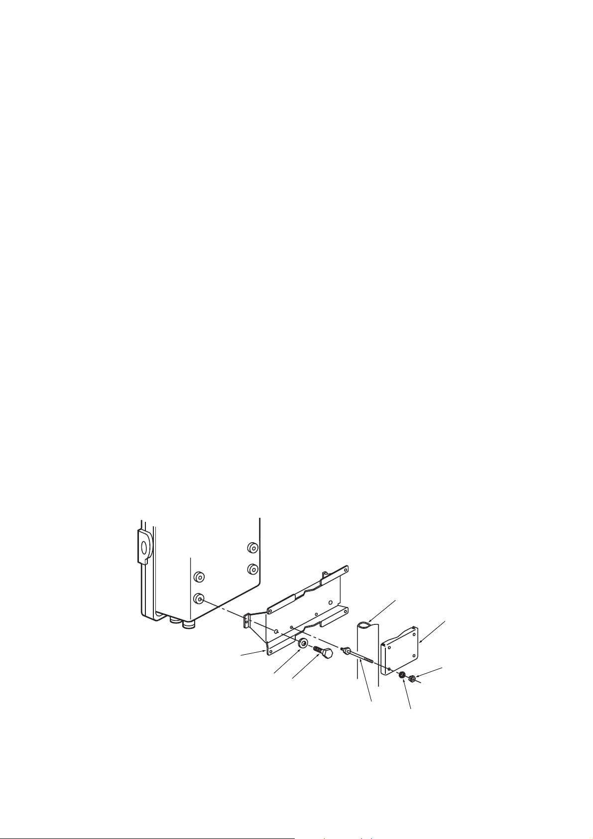
3.2 Installation of the Converter
3.2.1 Location
The following should be taken into consideration when installing the converter:
(1) Readability of the indicated values of moisture concentration or messages on the
converter display.
Easy and safe access to the converter for operating keys on the panel.
(2) Easy and safe access to the converter for checking and maintenance work.
(3) An ambient temperature of not more than 558C and little change in temperature
(recommended within 158C in a day).
(4) The normal ambient humidity (recommended between 40 to 75 %RH) and without
any corrosive gases.
(5) No vibration.
(6) Near to the detector.
(7) Not in direct rays of the sun. If the sun shines on the converter, prepare the hood (/
H) or other appropriate sunshade.
3.2.2 Mounting of the Converter
The converter can be mounted on a pipe (nominal JIS 50A: O.D. 60.5 mm), a wall or a
panel. The converter can be mounted at an angle to the vertical, however, it is recommended to mount it vertically plane.
Mount the converter as follows.
<Pipe Mounting>
(1) Prepare a vertical pipe of sufficient strength (nominal JIS 50A: O.D. 60.5 mm) for
mounting the converter. (Converter weighs approximately 6 kg.)
(2) Mount the converter on the pipe. Fix it firmly on the pipe in the procedure described
in Figure 3.3.
dMounting procedure
1. Put four bolts in the holes on the fitting.
2. Clamp the pipe with the fitting and a bracket,
with the four bolts passing through the bracket holes.
3. Secure the fitting and the bracket tightly to the pipe with
four washers and nuts.
A pipe to be mounted (nominal JIS 50A)
Bracket
*Fitting
*Washer
*Screw
Nut
3-4
Bolt
* Note: These fittings are attached to the equipment when it is delivered.
Figure 3.3 Pipe Mounting
Washer
F3.7E.EPS
IM 11M12A01-03E
Page 52

(1) Drill mounting holes through the wall as shown in Figure 3.4.
Unit: mm
Four holes 6 mm in diameter
or M5 screw
126.5
3. Installation
190
F3.8E.EPS
Figure 3.4 Mounting holes
(2) Mount the converter. Secure the converter on the wall using four screws.
Note: For wall mounting, the bracket and bolts are not used.
F3.5E.EPS
Figure 3.5 Wall Mounting
IM 11M12A01-03E
3-5
Page 53

<Panel Mounting>
(1) Cut out the panel according to Figure 3.6.
Unit: mm
+2
274
0
+2
183
0
F3.6E.EPS
Figure 3.6 Panel cutout sizes
(2) Remove the fitting from the converter by loosening the four screws.
(3) Insert the converter case into the cutout hole of the panel.
(4) Attach the mounting fitting which is once removed in step (2) again to the converter.
(5) Firmly fix the converter to the panel. Fully tighten the two clamp screws to hold the
panel with the fitting.
Clamp screw
Figure 3.7 Panel mounting
Washer
Nut
Fitting
F3.7E.EPS
3-6
IM 11M12A01-03E
Page 54

3.3 Installation of ZA8F Flow Setting Unit
3.3.1 Location
The following should be taken into consideration:
(1) Easy access to the unit for checking and maintenance work.
(2) Near to the detector and the converter for operating keys on the panel.
(3) No corrosive gas.
(4) An ambient temperature of not more than 558C and little changes of temperature.
(5) No vibration.
(6) Little exposure to rays of the sun or rain.
3.3.2 Mounting of ZA8F Flow Setting Unit
The flow setting unit can be mounted either on a pipe (nominal JIS 50A) or on a wall. It
should be positioned vertically so that the flowmeter works correctly.
<Pipe Mounting>
(1) Prepare a vertical pipe of sufficient strength (nominal JIS 50A: O.D. 60.5 mm) for
mounting the flow setting unit. (The unit weighs approximately 2 to 3.5 kg.)
(2) Mount the flow setting unit on the pipe by tightening the nuts with the U-bolt so that
the metal fitting is firmly attached to the pipe.
3. Installation
IM 11M12A01-03E
F3.8E.EPS
Figure 3.8 Pipe Mounting
3-7
Page 55

<Wall Mounting>
(1) Make a hole in the wall as illustrated in Figure 3.9.
Unit : mm
223
140
F3.9E.EPS
4 - f6 hole, or M5 screw
Figure 3.9 Mounting holes
(2) Mount the flow setting unit. Remove the pipe mounting parts from the mount fittings
of the flow setting unit and attach the unit securely on the wall with four screws.
F3.10E.EPS
Figure 3.10 Wall mounting
3-8
IM 11M12A01-03E
Page 56

3.4 Installation of ZR40H Automatic Calibration Unit
3.4.1 Location
The following should be taken into consideration:
(1) Easy access to the unit for checking and maintenance work.
(2) Near to the detector and the converter
(3) No corrosive gas.
(4) An ambient temperature of not more than 558C and little change of temperature.
(5) No vibration.
(6) Little exposure to rays of the sun or rain.
3.4.2 Mounting of ZR40H Automatic Calibration Unit
The Automatic Calibration Unit can be mounted either on a pipe (nominal JIS 50A ) or
on a wall. It should be positioned vertically so that the flowmeter works correctly.
<Pipe Mounting>
(1) Prepare a vertical pipe of sufficient strength (nominal JIS 50A: O.D. 60.5 mm) for
mounting of Automatic Calibration Unit. (The unit weights approximately 3.5 kg.)
(2) Mount the Automatic Calibration Unit on the pipe by tightening the nuts with the
U-bolt so that the metal fitting is firmly attached to the pipe.
3. Installation
IM 11M12A01-03E
F3.11E.EPS
Figure 3.11 Pipe Mounting
3-9
Page 57

<Wall Mounting>
(1) Make a hole in the wall as illustrated in Figure 3.12.
Unit : mm
223
140
F3.12E.EPS
4 - f6.5 hole, or M6 screw
Figure 3.12 Mounting holes
(2) Mount the Automatic Calibration Unit. Remove the pipe mounting parts from the
mount fittings of the flow setting unit and attach the unit on the wall with four
screws. When setting it with M5 bolts, use washers.
4-
[6.5
3-10
F3.13E.EPS
Figure 3.13 Wall Mounting
IM 11M12A01-03E
Page 58

3.5 Installation of E7044KF Case Assembly for the Calibration-gas Cylinder
The calibration gas unit case is used to store the G7001ZC zero gas cylinders.
3.5.1 Location
The following should be taken into consideration:
(1) Easy access for cylinder replacement
(2) Easy access for checking
(3) Near to the detector and converter as well as the flow setting unit.
(4) The temperature of the case should not exceed 408C due to rays of the sun or
radiated heat.
(5) No vibration
3.5.2 Mounting
Mount the calibration gas unit case on a pipe (nominal JIS 50A) as follows:
(1) Prepare a vertical pipe of sufficient strength (nominal JIS 50A: O.D. 60.5 mm) for
mounting the flow setting unit. (The sum of the calibration gas unit case and the
calibration gas cylinder weighs approximately 4.2 kg.)
(2) Mount the unit case on the pipe by tightening the nuts with the U-bolt so that the
metal fitting is firmly attached to the pipe.
3. Installation
IM 11M12A01-03E
A pipe to be mounted
(nominal JIS 50A: O.D. 60.5 mm)
F3.14E.EPS
Figure 3.14 Pipe Mounting
3-11
Page 59

3.6 Insulation Resistance Test
Even if the testing voltage is not so great that it causes dielectric breakdown, testing
may cause deterioration in insulation and a possible safety hazard. Therefore, conduct
this test only when it is necessary.
The applied voltage for this test shall be 500 V DC or less. The voltage shall be applied
for as short a time as practicable to confirm that insulation resistance is 20 MV or more.
Remove wiring from the converter and the detector.
1. Remove the jumper plate located between terminal G and the protective grounding
terminal.
2. Connect crossover wiring between L and N.
3. Connect an insulation resistance tester (with its power OFF). Connect (+) terminal to
the crossover wiring, and (-) terminal to ground.
4. Turn the insulation resistance tester ON and measure the insulation resistance.
5. After testing, remove the tester and connect a 100 kV resistance between the crossover wiring and ground to discharge.
6. Testing between the heater terminal and ground, contact output terminal and ground,
analog output/input terminal and ground can be conducted in the same manner.
7. Although contact input terminals are isolated, insulation resistance test cannot be
conducted because the breakdown voltage of the surge-preventing arrester between
the terminal and ground is low.
8. After conducting all the tests, replace the jumper plate as it was.
Insulation
resistance tester
crossover wiring
1FG2
AO1
(+)
12FG13
DI-114DI-215DI-C16AI
Contact
input 1
Temperature transmitter input
4 to 20mA
23
DO-124DO-125DO-226DO-227DO-328DO-329DO-430DO-431HTR32HTR33L34N35G
Remove wiring to connect external circuits
and connect crossover wiring
Separate-type Zirconia High Temperature Humidity
Analyzer, ZR402G Converter
+-
3
4
5
6
7
8
AO1
(-)
AO2
(+)
(+)
Contact
input 2
AO2
(-)
CJ
(+)
17
AI
(-)
ZERO
CJ
(-)
18
AC-
AC-
SPAN
Automatic Calibration Unit
9
TC
TC
(+)
(-)
19
20
AC-
COM
Solenoid valve
Span gas
for automatic
calibration
Solenoid valve for
automatic calibration
Zero gas
10
CELL
(+)
21FG22
FG
11
CELL
(-)
crossover wiring
Separate-type Zirconia High Temperature
Humidity Analyzer, ZR22G Detector
CELL
CELL
(+)
(-)TC(+)TC(-)CJ(+)CJ(-)
36
Remove
jumper plate
HTR HTR
3-12
Insulation
resistance tester
+-
Insulation
resistance tester
+-
F3.17E.EPS
IM 11M12A01-03E
Page 60
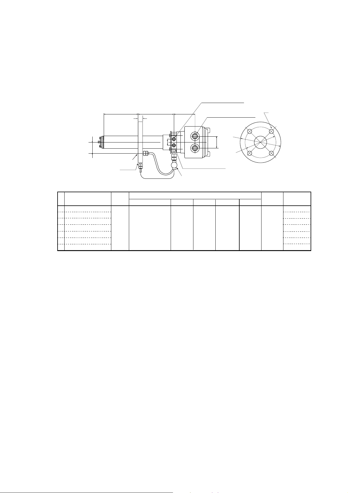
3. Installation
3.7 External Dimensions of Detectors with Pressure Compensation
dZR22G-hhh-h-A-P
Flange ; ANSI Class 150 2 RF SUS304
33
Reference gas outlet
Model, Code
ZR22G-040-h-A
ZR22G-070-h-A
ZR22G-100-h-A
ZR22G-150-h-A
ZR22G-200-h-A
ZR22G-250-h-A
ZR22G-300-h-A
L
Flange
L
400
700
1000
1500
2000
2500
3000
*1
ANSI Class 150
2 RF SUS304
156
t
PIPING : A
Specification
PIPING
:B
87
25
Rc1/4 or 1/4NPT
Calibration gas inlet
Stop Valve
A
152.4 120.6
Rc1/4 or 1/4NPT
Reference air inlet
2-G1/2, 2-1/2NPT etc.
Cable connection port
48
Flange
BC
4-f19
fA
fB
Flange
t
19
C
PIPING
A
Unit : mm
Weight
skgd
Approx. 6
Approx. 7
Approx. 8
Approx. 10
Approx. 12
Approx. 14
Approx. 15
F3.8.1E.EPS
IM 11M12A01-03E
3-13
Page 61

dZR22G-hhh-h-B-P
Flange ; ANSI Class 150 3 RF
L
t
42
Reference gas outlet
*1
Flange
156
25
PIPING
:B
PIPING : A
Rc1/4 or 1/4NPT
Reference air inlet
87
2-G1/2, 2-1/2NPT etc.
Cable connection port
48
Rc1/4 or 1/4NPT
Calibration gas inlet
Stop Valve
Unit : mm
C
fA
fB
Flange
Model, Code
ZR22G-040-h-B
ZR22G-070-h-B
ZR22G-100-h-B
ZR22G-150-h-B
ZR22G-200-h-B
ZR22G-250-h-B
ZR22G-300-h-B
L
400
700
1000
1500
2000
2500
3000
Specification
ANSI Class 150
3 RF SUS304
dZR22G-hhh-h-C-P
Flange ; ANSI Class 150 4 RF
L
t
45
Reference gas outlet
Model, Code
ZR22G-040-h-C
ZR22G-070-h-C
ZR22G-100-h-C
ZR22G-150-h-C
ZR22G-200-h-C
ZR22G-250-h-C
ZR22G-300-h-C
Flange
L
400
700
1000
1500
2000
2500
3000
*1
Specification
ANSI Class 150
4 RF SUS304
156
25
PIPING
: B
PIPING : A
Flange
A
190.5 152.4
BC
Rc1/4 or 1/4NPT
Reference air inlet
87
2-G1/2, 2-1/2NPT etc.
Cable connection port
Rc1/4 or 1/4NPT
Calibration gas inlet
Stop Valve
Flange
A
228.6 190.5
BC
48
4-f19
8-f19
fA
fB
t
24
Flange
t
24
PIPING
B
C
PIPING
B
Weight
skgd
Approx. 9
Approx. 10
Approx. 11
Approx. 13
Approx. 14
Approx. 16
Approx. 18
F3.8.2E.EPS
Unit : mm
Weight
skgd
Approx. 11
Approx. 12
Approx. 13
Approx. 15
Approx. 17
Approx. 18
Approx. 20
F3.8.3E.EPS
3-14
IM 11M12A01-03E
Page 62

dZR22G-hhh-h-E-P
Flange ; DIN PN10 DN50
L
3. Installation
Rc1/4 or 1/4NPT
Reference air inlet
156
t
87
2-G1/2, 2-1/2NPT etc.
Cable connection port
C
33
*1
Reference gas outlet
Flange
Model, Code
ZR22G-040-h-E
ZR22G-070-h-E
ZR22G-100-h-E
ZR22G-150-h-E
ZR22G-200-h-E
ZR22G-250-h-E
ZR22G-300-h-E
L
400
700
1000
1500
2000
2500
3000
dZR22G-hhh-h-F-P
Flange ; DIN PN10 DN80
L
PIPING
: B
PIPING : A
Specification
DIN PN10 DN50
SUS304
156
t
25
Rc1/4 or 1/4NPT
Calibration gas inlet
Stop Valve
A
165 125
87
48
Flange
BC
4-f18
Rc1/4 or 1/4NPT
Reference air inlet
2-G1/2, 2-1/2NPT etc.
Cable connection port
Flange
t
18
PIPING
A
Weight
skgd
Approx. 7
Approx. 8
Approx. 9
Approx. 10
Approx. 12
Approx. 14
Approx. 16
F3.8.4E.EPS
Unit : mm
C
IM 11M12A01-03E
42
Reference gas outlet
Model, Code
ZR22G-040-h-F
ZR22G-070-h-F
ZR22G-100-h-F
ZR22G-150-h-F
ZR22G-200-h-F
ZR22G-250-h-F
ZR22G-300-h-F
Flange
L
400
700
1000
1500
2000
2500
3000
*1
PIPING : A
Specification
DIN PN10 DN80
SUS304
25
PIPING
: B
Rc1/4 or 1/4NPT
Calibration gas inlet
Stop Valve
Flange
A
200 160
BC
48
8-f18
Flange
t
20
PIPING
B
Weight
skgd
Approx. 8
Approx. 10
Approx. 11
Approx. 12
Approx. 14
Approx. 16
Approx. 18
F3.8.5E.EPS
3-15
Page 63
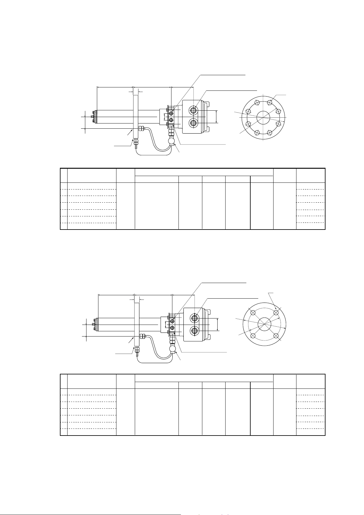
dZR22G-hhh-h-G-P
Flange ; Equivalent to DIN PN10 DN100
L
45
Reference gas outlet
Flange
*1
t
156
25
PIPING
:B
PIPING : A
Rc1/4 or 1/4NPT
Reference air inlet
87
2-G1/2, 2-1/2NPT etc.
Cable connection port
48
Rc1/4 or 1/4NPT
Calibration gas inlet
Stop Valve
Unit : mm
C
fA
fB
Flange
Model, Code
ZR22G-040-h-G
ZR22G-070-h-G
ZR22G-100-h-G
ZR22G-150-h-G
ZR22G-200-h-G
ZR22G-250-h-G
ZR22G-300-h-G
L
400
700
1000
1500
2000
2500
3000
Specification
DIN PN10 DN100
SUS304
dZR22G-hhh-h-K-P
Flange ; Eguivalent to JIS 5K 65 FF
L
33
Reference gas outlet
Flange
*1
t
156
PIPING
: B
PIPING : A
87
25
Rc1/4 or 1/4NPT
Calibration gas inlet
Stop Valve
Flange
A
220 180
BC
Rc1/4 or 1/4NPT
Reference air inlet
2-G1/2, 2-1/2NPT etc.
Cable connection port
48
8-f18
fA
fB
t
20
Flange
C
PIPING
B
Weight
skgd
Approx. 9
Approx. 11
Approx. 12
Approx. 13
Approx. 15
Approx. 17
Approx. 19
F3.8.6E.EPS
Unit : mm
3-16
Model, Code
ZR22G-040-h-K
ZR22G-070-h-K
ZR22G-100-h-K
ZR22G-150-h-K
ZR22G-200-h-K
ZR22G-250-h-K
ZR22G-300-h-K
L
400
700
1000
1500
2000
2500
3000
Specification
JIS 5K 65 FF
SUS304
Flange
A
155 130
BC
4-f15
t
14
PIPING
A
IM 11M12A01-03E
Weight
skgd
Approx. 6
Approx. 7
Approx. 8
Approx. 10
Approx. 12
Approx. 14
Approx. 15
F3.8.7E.EPS
Page 64

3. Installation
dZR22G-hhh-h-L-P
Flange ; JIS 10K 65 FF
L
33
Reference gas outlet
Model, Code
ZR22G-040-h-L
ZR22G-070-h-L
ZR22G-100-h-L
ZR22G-150-h-L
ZR22G-200-h-L
ZR22G-250-h-L
ZR22G-300-h-L
*1
Flange
L
400
700
1000
1500
2000
2500
3000
156
t
PIPING
PIPING : A
Specification
JIS 10K 65 FF
SUS304
: B
25
Rc1/4 or 1/4NPT
Reference air inlet
87
2-G1/2, 2-1/2NPT etc.
Cable connection port
Rc1/4 or 1/4NPT
Calibration gas inlet
Stop Valve
Flange
A
175 140
BC
48
fA
fB
4-f19
C
Flange
t
18
PIPING
A
Unit : mm
Weight
skgd
Approx. 7
Approx. 8
Approx. 9
Approx. 11
Approx. 13
Approx. 14
Approx. 16
F3.8.8E.EPS
dZR22G-hhh-h-M-P
Flange ; JIS 10K 80 FF
L
42
Reference gas outlet
Model, Code
ZR22G-040-h-M
ZR22G-070-h-M
ZR22G-100-h-M
ZR22G-150-h-M
ZR22G-200-h-M
ZR22G-250-h-M
ZR22G-300-h-M
*1
Flange
L
400
700
1000
1500
2000
2500
3000
156
t
PIPING
PIPING : A
Specification
JIS 10K 80 FF
SUS304
: B
25
Rc1/4 or 1/4NPT
Reference air inlet
87
2-G1/2, 2-1/2NPT etc.
Cable connection port
48
Rc1/4 or 1/4NPT
Calibration gas inlet
Stop Valve
Flange
A
185 150
BC
fA
8-f19
fB
Flange
t
18
C
PIPING
B
Unit : mm
Weight
skgd
Approx. 7
Approx. 8
Approx. 9
Approx. 11
Approx. 13
Approx. 15
Approx. 16
F3.8.9E.EPS
IM 11M12A01-03E
3-17
Page 65

dZR22G-hhh-h-P-P
Flange ; JIS 10K 100 FF
L
45
Reference gas outlet
*1
Flange
t
156
25
PIPING
: B
PIPING : A
Rc1/4 or 1/4NPT
Reference air inlet
87
2-G1/2, 2-1/2NPT etc.
Cable connection port
48
Rc1/4 or 1/4NPT
Calibration gas inlet
Stop Valve
Unit : mm
C
fA
fB
Flange
Model, Code
ZR22G-040-h-P
ZR22G-070-h-P
ZR22G-100-h-P
ZR22G-150-h-P
ZR22G-200-h-P
ZR22G-250-h-P
ZR22G-300-h-P
L
400
700
1000
1500
2000
2500
3000
JIS 10K 100 FF
dZR22G-hhh-h-R-P
Flange ; JPI Class 150 4 RF
L
t
45
Reference gas outlet
*1
Flange
Specification
SUS304
156
PIPING
: B
PIPING : A
25
Flange
A
210 175
BC
Rc1/4 or 1/4NPT
Reference air inlet
87
2-G1/2, 2-1/2NPT etc.
Cable connection port
48
Rc1/4 or 1/4NPT
Calibration gas inlet
Stop Valve
8-f19
fA
fB
t
18
Flange
PIPING
B
C
Weight
skgd
Approx. 8
Approx. 10
Approx. 11
Approx. 12
Approx. 14
Approx. 16
Approx. 18
F3.8.10.EPS
Unit : mm
3-18
Model, Code
ZR22G-040-h-R
ZR22G-070-h-R
ZR22G-100-h-R
ZR22G-150-h-R
ZR22G-200-h-R
ZR22G-250-h-R
ZR22G-300-h-R
L
400
700
1000
1500
2000
2500
3000
Specification
JPI Class 150
4 RF SUS304
Flange
A
229 190.5
BC
8-f19
t
24
PIPING
B
IM 11M12A01-03E
Weight
skgd
Approx. 11
Approx. 12
Approx. 13
Approx. 15
Approx. 17
Approx. 19
Approx. 20
F3.8.11.EPS
Page 66

dZR22G-hhh-h-S-P
Flange ; JPI Class 150 3 RF
L
t
42
Reference gas outlet
*1
Flange
156
25
PIPING
: B
PIPING : A
Rc1/4 or 1/4NPT
Reference air inlet
87
2-G1/2, 2-1/2NPT etc.
Cable connection port
48
Rc1/4 or 1/4NPT
Calibration gas inlet
Stop Valve
3. Installation
Unit: mm
C
fA
fB
Flange
Model, Code
ZR22G-040-h-S
ZR22G-070-h-S
ZR22G-100-h-S
ZR22G-150-h-S
ZR22G-200-h-S
ZR22G-250-h-S
ZR22G-300-h-S
L
400
700
1000
1500
2000
2500
3000
dZR22G-hhh-h-W-P
Flange ; Westinghouse
L
33
Reference gas outlet
*1
Flange
Specification
JPI Class 150
3 RF SUS304
156
t
PIPING
PIPING : A
: B
25
Flange
A
190 152.4
BC
Rc1/4 or 1/4NPT
Reference air inlet
87
2-G1/2, 2-1/2NPT etc.
Cable connection port
48
Rc1/4 or 1/4NPT
Calibration gas inlet
Stop Valve
4-f19
fA
fB
t
24
Flange
PIPING
B
Weight
skgd
Approx. 9
Approx. 10
Approx. 11
Approx. 13
Approx. 14
Approx. 16
Approx. 18
F3.8.12E.EPS
Unit: mm
C
IM 11M12A01-03E
Model, Code
ZR22G-040-h-W
ZR22G-070-h-W
ZR22G-100-h-W
ZR22G-150-h-W
ZR22G-200-h-W
ZR22G-250-h-W
ZR22G-300-h-W
L
400
700
1000
1500
2000
2500
3000
Specification
Westinghouse
Flange
A
155 127
BC
4-f11.5
t
14
PIPING
A
Weight
skgd
Approx. 6
Approx. 7
Approx. 8
Approx. 10
Approx. 12
Approx. 14
Approx. 15
F3.8.13E.EPS
3-19
Page 67

Page 68

4. Piping
This chapter describes piping procedures based on three typical system configurations
for EXAxt ZR Separate-type Zirconia High-temperature Humidity Analyzer.
• Ensure that each check valve, stop valve and joint used for piping do not allow
• Be sure to conduct leakage test after pipes piping.
• Basically, apply instrument air (dehumidified by cooling to the dew point –20°C or
• When the instrument uses natural convection for reference gas, ambient air near the
4. Piping
leakage. Especially, if there is any leakage of from the calibration gas pipes and
joints, it may cause clogging of the piping or incorrect calibration.
lower, and removing any dust, oil mist and the like) for the reference gas piping.
detector is used for reference gas; therefore the accuracy of analysis will be affected
by ambient temperature changes or the like. If more accurate analysis is necessary,
use instrument air (dehumidified by cooling to the dew point –20°C or lower, and
removing any dust, oil mist and the like) for reference gas.
Stable analyzing can be conducted when using instrument air.
4.1 Piping for System 1
The piping in System 1 is illustrated in Figure 4.1.
Separate type Zirconia
High Temperature Humidity Analyzer
Model ZR22G Detector
Stop valve
Calibration gas
Figure 4.1 Piping in System 1
Piping in System 1 is as follows:
• Place a stop valve through the nipple at the calibration gas inlet of the detector. Then
mount a joint for a 6 mm (O.D.)34 mm (I.D.) soft tube at the stop valve connection
hole of the inlet side (see Section 4.1.2). The tube is to be connected to this joint
only during calibration.
Model ZR402G Converter
EXA
ZR402G
Signal
(6-core shield cable)
Heater (2-core)
Model ZO21S Standard gas unit
~
100 to 240 V AC
~
Contact input
Analog output, contact output
Digital output (HART)
100/110/115
200/220/240 V AC
F4.1E.EPS
IM 11M12A01-03E
CAUTION
• The stop valve should be connected directly to the detector. If any piping is present
between the detector and the stop valve, water may condense in the pipe, which may
cause damage to the sensor by rapid cooling when the calibration gas is introduced.
The stop valve should be closed except while the calibration gas is being introduced.
Piping is required if the air around the detector is not clean.
• The reference gas should have an oxygen concentration identical to that of fresh air
(21%).
4-1
Page 69

• It is recommended to use ZH21B dust protector to protect the probe output from dust
agitation (i.e., to prevent combustible materials from entering the probe cell) where
humidity measurements are made under dusty or combustible, such as paper dust,
environment.
4.1.1 Parts Required for Piping in System 1
Check that the parts listed in Table 4.1 are ready.
Table 4.1
Detector Piping location Parts Note
General-use Calibration gas inlet Stop valve Recommended by YOKOGAWA
detector (L9852CB or G7016XH)
nipple * Rc1/4 or 1/4 NPT generic parts
joint for tube connection Rc1/4 (1/4NPT) for f63f4mm generic parts
Reference gas inlet (sealed up) (when piping is required, refer to section 4.1.3)
Note : Parts with marking * are used when required.
4.1.2 Connection to the Calibration Gas Inlet
When carrying out calibration, connect the piping (6(O.D)34(I.D.) mm tube) from the
standard gas unit to the calibration gas inlet of the detector. First, mount a stop valve (of
a quality specified by YOKOGAWA) or a nipple (found on the open market) as illustrated in Figure 4.2, and mount a joint (also found on the open market) at the stop valve
tip. (The stop valve may be mounted on the detector prior to shipping the detector is
shipped.)
soft tube
T4.1E.EPS
Note : Mount the stop valve close to the detector.
Tube connection
joint
Figure 4.2 Connection to the calibration gas inlet
4.1.3 Connection to the Reference Gas Inlet
• Normally, no piping is required for the reference gas inlet when the equipment uses
natural convection for reference gas (models ZR22G-h-h-h-C). Leave the plug as it
is. If the air around the detector is polluted and the necessary oxygen concentration
(21 vol%O2) cannot be obtained, prepare piping the same as which described in
Section 4.2, System 2.
• When the equipment uses instrument air for the reference gas, piping is required as
described in Section 4.2, System 2 (models ZR22G-h-h-h-E).
NippleStop valve
F4.2E.EPS
4-2
IM 11M12A01-03E
Page 70

4.2 Piping for System 2
Piping in System 2 is illustrated in Figure 4.7.
Separate type Zirconia
High Temperature Humidity Analyzer
Model ZR22G Detector
Model ZR402G Converter
EXA
ZR402G
4. Piping
Stop valve
or Check valve
Calibration gas
Reference
gas
Signal
(6-core shield cable)
Heater (2-core)
Model ZA8F flow setting unit
Flowmeter
Needle
valve
Calibration gas pressure regulator
Calibration gas
unit case
100 to 240 V AC
~
Contact input
Analog output, contact output
Digital output (HART)
Air Set
Instrument air
Span gas (Same as Zero gas
Calibration unit)
Zero gas
cylinder
F4.7E.EPS
Figure 4.7 Piping for System 2
Piping in System 2 is as follows:
• Place a stop valve or check valve through the nipple at the calibration gas inlet of the
detector.
• It is recommended to use ZH21B dust protector to protect the probe output from dust
agitation (i.e., to prevent combustible materials from entering the probe cell) where
humidity measurements are made under dusty or combustible environment
4.2.1 Piping Parts for System 2
Check that the parts listed in Table 4.2 are ready.
Table 4.2
Detector Piping location Parts Note
General-use Calibration gas inlet Stop valve or check valve Recommended by YOKOGAWA
detector (L9852CB or G7016XH)
Reference gas inlet Air set Recommended by YOKOGAWA
Note : Parts with marking * are used when required.
Provided by YOKOGAWA
(K9292DN or K9292DS)
Nipple * Rc1/4 or 1/4 NPT generic parts
Zero gas cylinder User's scope
Gas pressure regulator Recommended by YOKOGAWA
(G7013XF or G7014XF)
Joint for tube connection Rc1/4 or 1/4 NPT generic parts
(K9473XH/K9473XJ or
G7004XF/ K9473XG)
Joint for tube connection Rc1/4 or 1/4 NPT generic parts
T4.2E.EPS
IM 11M12A01-03E
4-3
Page 71

4.2.2 Piping for the Calibration Gas
This piping is to be installed between the zero gas cylinder and the ZA8F flow setting
unit, and between the ZA8F flow setting unit and the ZR22G detector.
The cylinder should be placed in a calibration gas unit case or the like to avoid any
direct sunlight or radiant heat so that the gas cylinder temperature does not exceed 408 C.
Mount a regulator valve (specified by YOKOGAWA) on the cylinder.
Mount a check valve or the stop valve (specified by YOKOGAWA) or the nipple (found
on the open market) at the calibration gas inlet of the detector as illustrated in Figure
4.8. (The check valve or the stop valve may have been mounted on the detector when
shipped.) Connect the flow setting unit and the detector to a stainless steel pipe 6 mm
(O.D.) 34 mm or larger (I.D.) (or nominal size 1/4 inch).
Stop valve or Check valve
Piping for the Calibration gas, 6 mm (O.D.)
by 4 mm (I.D.) Stainless steel pipe
Piping for the Reference gas, 6 mm (O.D.)
by 4 mm (I.D.)Stainless steel pipe
Figure 4.8 Piping for the Calibration Gas Inlet
4.2.3 Piping for the Reference Gas
Reference gas piping is required between the air source (instrument air) and the flow
setting unit, and between the flow setting unit and the detector.
Insert the air set next to the flow setting unit in the piping between the air source and
the flow setting unit.
Use a 6 mm (O.D.) 3 4 mm or larger (I.D.) (or nominal size 1/4 inch) stainless steel
pipe between the flow setting unit and the detector.
F4.8E.EPS
4-4
IM 11M12A01-03E
Page 72

4.3 Piping for System 3
Piping in System 3 is illustrated in Figure 4.9. In System 3, calibration is automated;
however, the piping is basically the same as that of System 2. Refer to Section 4.2.
Adjust secondary pressure of both the air set and the zero gas reducing valve so that
these two pressures are approximately the same. The flow rate of zero and span gases
(normally instrument air) are set by a single needle valve.
After installation and wiring, check the calibration contact output (see Sec. 7.10.2), and
adjust zero gas reducing valve and calibration gas needle valve so that zero gas flow is
within the permitted range. Next check span gas calibration contact output and adjust
air set so that span gas flow is within the permitted range.
4. Piping
CHECK
OUT
flow
meter
REF
OUT
flow
meter
*2 *2
EV1 EV2
ZERO GAS IN
AIR IN
Instrument air Approx.
1.5 l/min.
*2: Needle valve comes with flowmeter
F2.6-3E.EPS
It is recommended to use ZH21B dust protector to protect the probe output from dust
agitation (i.e., to prevent combustible materials from entering the probe cell) where
humidity measurements are made under dusty or combustible environment.
Separate type Zirconia
High Temperature Humidity Analyzer
Model ZR22G Detecor
Model ZR402G Converter
EXA
ZR402G
IM 11M12A01-03E
Conduit
Signal
Check valve
Reference gas
Calibration gas
(6-core shield cable)
Heater (2-core shield cable)
Model ZR40H Auto Calibration unit
Figure 4.9 Piping for System 3
Flowmeter
Needle
valve
100 to 240 V AC
~
Air Set
Contact input
Analog output, contact output
Digital output (HART)
Instrument air
Calibration gas pressure regulator
Calibration gas
unit case
Zero gas cylinder
F4.9E.EPS
4-5
Page 73

5. Wiring
In this Chapter, the wiring necessary for connection to the EXAxtZR Separate-type
Zirconia High-temperature Humidity Analyzer is described.
5.1 General
CAUTION
• NEVER supply current to the converter or any other device constituting a power
• This product complies with CE marking.
1. Install an external switch or circuit breaker to the power supply of the converter.
2. Use an external switch or circuit breaker rated 5A and conforming with IEC 947-1 or
3. It is recommended that the external switch or circuit breaker be mounted in the same
4. The external switch or circuit breaker should be installed within the reach of the
5. Wiring
circuit in combination with the converter, until all wiring is completed.
Where compliance with CE marking is necessary, the following piping procedure is
necessary.
IEC947-3.
room as the converter.
operator, and marked as the power supply switch of this equipment.
IM 11M12A01-03E
5-1
Page 74

Wiring procedure
Wiring should be preformed according to the following procedure:
1. Be sure to connect the shield line to FG terminal of the converter.
2. The outer sheath of the signal line should be stripped to a length of 50 mm or less.
The outer sheath of the power cable should be stripped to a length of 20 mm or less.
3. Signals may be affected by noise emission when the signal lines, power cable and
heater cable are located in the same conduit. When using conduit, signal lines should
be installed in a separate conduit from power and heater cables.
4. Install metal blind plug(s) in unused cable connection gland(s) of the converter.
5. Metal conduit should be grounded.
6. The following cables are used for wiring:
Table 5.1 Cable specifications
Terminal name of converter Name Need for shields Cable type Number of wires
CELL+, CELLHTR TC+, HTR TCCJ+, CJHEATER
L, N,
AO-1+, AO-1-, AO-2+, AO-2DO-1, DO-2, DO-3, DO-4
AC-Z, AC-S, AC-C
DI-1, DI-2, DI-C
Note *: When the case is used for protective grounding, use a 2-wire cable.
Converter signal
Converter heater
Power supply
Analog output
Contact output
Automatic
Calibration unit
Contact input
s
s
CVVS
CVV
CVV
CVVS
CVV
CVV
CVV
6
2
2 or 3 *
2 or 4
2 to 8
3
3
T5.1E.EPS
CAUTION
• Select suitable cable O.D. to match the cable gland size.
• Protective grounding should be connected (Class 3) grounding (the grounding
resistance is 100V or less).
• Special cable length should be taken consideration.
For detail of the HART communication, refer to IM11M12A01-51E HART Protocol
Section 1.1.2 Communication Line Requirement..
5-2
IM 11M12A01-03E
Page 75

5.1.1 Terminals for the External Wiring in the Converter
Open the front door and remove the terminal cover to gain access to the converter
external wiring terminals (see Figure 5.2).
CAUTION
After wiring necessary cable to the converter terminals, be sure to fix the terminal
covering plate with two screws again.
5. Wiring
Front door
5.1.2 Wiring
Terminals are visible
when the terminal cover is removed.
Cable inlet
F5.2E.EPS
Figure 5.2 Terminals for external wiring in the converter
Connect the following wiring to the converter. It requires a maximum of eight wiring
connections as shown below.
(1) Detector output (connects the converter with the detector.)
(2) Detector heater power (connects the converter with the detector.)
(3) Analog output signal
(4) Power and ground
(5) Contact output
(6) Operation of the solenoid valve of automatic calibration unit
(7) Contact input
(8) Temperature input
IM 11M12A01-03E
5-3
Page 76

Model ZR402G Separate type Zirconia High Temperature Humidity Analyzer,
Converter
Analog
output 1
4-20 mA DC
Digital output
Analog
output 2
4-20 mA DC
Model ZR22G Separate type Zirconia
High Temperature Humidity Analyzer, Detector
1FG2
12FG13
DI-114DI-215DI-C16AI
Temperature transmitter input
4 to 20mA
23
DO-124DO-125DO-226DO-227DO-328DO-329DO-430DO-431HTR32HTR33L34N35G36FG HTR HTR
Contact
output 1
3
AO1
AO1
(+)
(-)
Contact
input 2
Contact input 1
Contact
output 2
AO2
(+)
4
5
AO2
(-)
(+)
Contact
output 3
6
7
8
9
10
CJ
CJ
TC
(+)
(-)
17
18
AI
AC-
(-)
AC-
ZERO
SPAN
Solenoid valve for span gas
for automatic calibration
Contact
output 4
TC
(+)
19
Flow setting unit
(-)
20
AC-
COM
Solenoid valve for zero gas
for automatic calibration
CELL
(+)
21FG22
FG
11
CELL
(-)
100-240V AC
50/60 Hz
CELL
CELL
(+)
(-)TC(+)TC(-)CJ(+)CJ(-)
*1
*1 The protective grounding for the converter should be connected either the protective ground terminal in the equipment or
the ground terminal on the case.
Standard regarding grounding: Ground to earth (Class 3 grounding), ground resistance: 100 V or less.
Figure 5.3 Wiring connection to the converter
5.1.3 Mounting of Cable Gland
*1
F5.3E.EPS
For each cable connection opening of the converter, mount a conduit that matches the
thread size or a cable gland.
EXA
ZR402G
8-G1/2, 8-1/2NPT
or the like
(Wiring connection)
Ground terminal (M4)
Adaptor for 1/2 NPT thread
F5.4E.EPS
Figure 5.4 Cable gland mounting
5-4
IM 11M12A01-03E
Page 77

5.2 Wiring for Detector Output
This wiring enables the converter to receive cell output from the detector, output from a
thermocouple and a reference junction compensation signal. Install wires that allow for
10 V of loop resistance or less. Keep detector signal wiring away from power wiring.
Separate the signal and the power wiring.
(1) Ambient temperature of the detector: 808C or less
Detector Converter
5. Wiring
CELL(+)
CELL(-)
TC(+)
TC(-)
CJ(+)
CJ(-)
Shielded cables
(2) Ambient temperature of the detector: exceeding 808C
Detector Converter
CELL(+)
CELL(-)
TC(+)
TC(-)
CJ(+)
CJ(-)
Heat-resistant wiring
Terminal box
Shielded cables
Figure 5.5 Wiring for detector output
CELL(+)
CELL(-)
TC(+)
TC(-)
CJ(+)
CJ(-)
FG
CELL(+)
CELL(-)
TC(+)
TC(-)
CJ(+)
CJ(-)
FG
F5.5E.EPS
CAUTION
If shielded cables cannot be used between the detector and the terminal box, for example, when heat-resistant wiring is used, locate the detector and the terminal box as
close together as possible.
5.2.1 Cable Specifications
Basically, PVC sheathed PVC insulated cable (six core) is used for this wiring. When
the ambient temperature of the detector exceeds 80°C, install a terminal box, and
connect with the detector using six-piece 600-V silicon rubber insulated glass braided
wire.
IM 11M12A01-03E
5-5
Page 78

5.2.2 Connection to the Detector
To connect cables to the detector, proceed as follows:
(1) Mount conduits of the specified thread size or cable glands to the wiring connections
of the detector.
The detector may need to be removed in future for maintenance, so be sure to allow
a sufficient cable length.
(2) If the ambient temperature at the location of wire installation is 80 to 1508 C, be sure
to use a flexible metallic wire conduit. If a non-shielded “ 600V silicon rubber
insulated glass braided wire “ is used, keep the wire away from noise sources to
avoid noise interference.
(3) Figure 5.6 shows the layout of the detector terminals.
TC 1(with Si TUBE)
CELL 1
TC 2
CELL
CELL
(+)
(-)TC(+)TC(-)CJ(+)CJ(-)
To the
ground
HTR HTR
To the
converter
or the
terminal box
123456
TCCELL CJ
H
T
87
R
To the
converter
or the
terminal box
Figure 5.6 Detector terminals
The sizes of the terminal screw threads are M3.5 except for the M4 on grounding
terminal. Each wire in the cable should be terminated in the corresponding size of
crimp-on terminal(*1).
F5.6E.EPS
5-6
*1 If the ambient temperature at the detector installation site exceeds 608 C, use a “ bare
crimp-on terminal”.
(4) Except when a “600V silicon rubber insulated glass braided wire” is used, connect
the cable shield to the FG terminal of the converter.
IM 11M12A01-03E
Page 79

5.2.3 Connection to the Converter
To connect the wiring to the converter, proceed as follows:
(1) M4 screws are used for the terminals of the converter. Each wire in the cable should
be terminated in the corresponding sige crimp-on terminal.
(2) When a rubber insulated glass braided wire is used for wiring to the detector, use a
terminal box. For wiring between the terminal box and the converter, use basically a
cable, e.g. PVC sheathed PVC insulated cable, rather than individual wires.
Note
The above is to prevent moisture or corrosive gas from entering the converter and to
ground the detector without fail.
5. Wiring
IM 11M12A01-03E
5-7
Page 80

5.3 Wiring for Power to Detector Heater
This wiring provides electric power from the converter to the heater for heating the
sensor in the detector.
(1) Ambient temperature of the detector: 808C or less
Detector Converter
HTR 7
HTR 8
(2) Ambient temperature of the detector: exceeding 808C
Detector Converter
HTR 7
HTR 8
Figure 5.7 Wiring for power to the detector heater
5.3.1 Cable Specifications
HEATER
Terminal box
HEATER
Heat-resistant wiring
F5.7E.EPS
Basically, PVC insulated PVC sheathed control cables (2 cores) are used for this wiring.
When the ambient temperature of the detector exceeds 808 C, install a terminal box, and
connect to the detector using six 600V silicon rubber insulated glass braided wires.
5.3.2 Connection to Detector
When connecting the cable to the detector, proceed as follows:
(1) Mount cable glands or conduits of the specified thread size to the wiring connections
of the detector.
The detector may need to be removed in future for maintenance, so be sure to allow
sufficient cable length.
(2) If the ambient temperature at the location of wire installation is 80 to 1508 C, be sure
to use a flexible metallic conduit for the wire. If a non-shielded 0 600V silicon rubber
insulated glass braided wire 0 is used, keep the wire away from noise sources, to
avoid noise interference.
(3) The size of the terminal screw threads is M3.5. Each cable should be terminated in
the corresponding size crimp-on terminals (*1) respectively.
*1 If the ambient temperature at the detector installation site exceeds 608 C, use a 0 bare
crimp-on terminal0 .
5-8
IM 11M12A01-03E
Page 81

CAUTION
•Before opening the detector cover, loosen the lock screw. If the screw is not loosened
first, the screw will damage the cover, and the terminal box will require replacement.
When opening and closing the cover, remove any sand particles or dust to avoid
gouging the thread.
• Notice when closing the cover of the detector
After screwing the cover in the detector body, secure it with the lock screw.
Lock screw
5. Wiring
Figure 5.8
5.3.3 Connection to Converter
To connect the wiring to the converter, proceed as follows:
(1) M4 screws are used for the terminal of the converter. Each cable should be termi-
nated in the corresponding size crimp-on terminals.
(2) When a rubber insulated glass braided wire is used for wiring to the detector, use a
terminal box. For wiring between the terminal box and the converter, use basically a
cable, e.g., PVC sheathed PVC insulated cable rather than wire.
Note
The above is to prevent moisture or corrosive gas from entering the converter. Where
the ambient environment of the detector and the converter is well-maintained, it is
permissible allowed to connect the wiring from the detector directly to the converter
with protection by conduits.
WARNING
Detector cover
F5.8E.EPS
IM 11M12A01-03E
This wiring is to carry power for the heater. Be careful to wire the correct terminals, and
be careful not to ground or short circuit terminals when wiring, as otherwise the
instrument may be damaged.
5-9
Page 82

5.4 Wiring for Analog Output
This wiring is for transmitting 4 to 20 mA DC output signals to a device, e.g. recorder.
Maintain the load resistance including the wiring resistance at 550V or less.
Converter
AO1(+)
AO1(-)
AO2(+)
AO2(-)
FG
Figure 5.9 Wiring for analog output
5.4.1 Cable Specifications
For this wiring, use a 2-core or a 4-core shielded cable.
5.4.2 Wiring Procedure
(1) M4 screws are used for the terminals of the converter. Each wire of the cable should
be terminated in corresponding crimp-on terminals. Ensure that the cable shield is
connected to the FG terminal of the converter.
(2) Be sure to connect “+” and “-” polarities correctly.
Shielded cable
Receiver 1
1
2
Receiver 2
1
2
F5.9E.EPS
5-10
IM 11M12A01-03E
Page 83

5.5 Power and Grounding Wiring
This wiring supplies power to the converter and grounds the converter/detector.
5. Wiring
Grounding to the ground terminal
on the converter case
FG terminal
Figure 5.10 Power and Grounding wiring
5.5.1 Power Wiring
Connect the power wiring to the L and N terminals of the converter. Proceed as follows:
(1) Use a 2-core or a 3-core shielded cable.
(2) The size of converter terminal screw threads is M4. Each cable should be terminated
corresponding crimp-on terminals.
5.5.2 Grounding Wiring
Converter case
Lock washer
Crimp-on terminal
the ground wire
Converter
LNG
100 - 240VAC
50/60Hz
Detector
Earth
Jumper plate
F5.10E.EPS
The ground wiring of the detector should be connected to the ground terminal of the
detector case. The ground wiring of the converter should be connected to either the
ground terminal of the converter case or the protective ground terminal in the equipment. The ground terminals of the detector and the converter are of size M4. Proceed as
follows:
(1) Keep ground resistance to 100V or less (JIS Class 3 ground).
(2) When the ambient temperature of the wiring installation is 80 to 1508 C for the wiring
of the detector, use wiring material with sufficient heat resistance.
(3) When connecting the ground wiring to the ground terminal of the converter case, be
sure that the lock washer is in contact with the case surface (see Figure 5.10.).
(4) Ensure that the jumper plate is connected between the G terminal and the protective
ground terminal of the converter.
IM 11M12A01-03E
5-11
Page 84

5.6 Wiring for Contact Output
Contact outputs 1 to 3 can be freely assigned to "low limit alarm", "high limit alarm",
etc. user selectable, but the assignment of contact output 4 is fixed ("error output"). And
the action (contact closed on error output) also cannot be changed.
When using these contact outputs, install the wiring as follows:
Converter
DO-1
DO-1
DO-2
DO-2
DO-3
DO-3
DO-4
DO-4
Figure 5.11 Contact output wiring
5.6.1 Cable Specifications
Number of wires in cable varies depending on the number of contact used.
5.6.2 Wiring Procedure
Terminal box Annunciator or the like
#1 Output
#2 Output
#3 Output
#4 Output
F5.11E.EPS
(1) M4 screws are used for the terminals of the converter. Each wire in the cable should
be terminated in the corresponding crimp-on terminal.
(2) The capacities of the contact output relay are 30 V DC 3 A, 250V AC 3 A. Connect
a load (e.g. pilot lamp and annunciator) within these limits.
5-12
IM 11M12A01-03E
Page 85
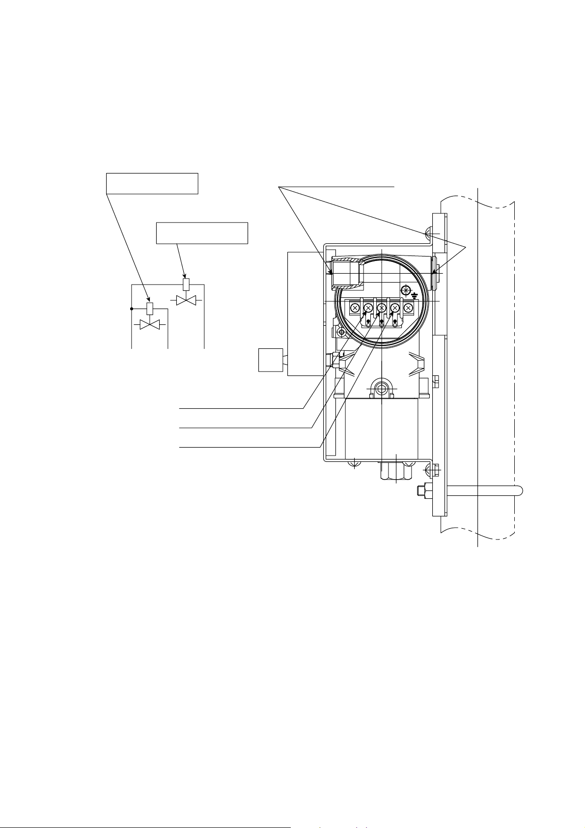
5.7 Wiring for ZR40H Automatic Calibration Unit
This wiring is for operating the solenoid valve for the zero gas and the span gas in the
ZR40H Automatic Calibration Unit, in a system where the calibration gas flow rate is
automatically controlled (e.g. System configuration 3). When installing this wiring,
proceed as follows:
Wiring inlet
Span gas solenoid valve
Zero gas solenoid valve
2-G1/2, Pg13.5, M20 or 1/2NPT
COMMON
SPAN
ZERO
5. Wiring
COMMON SPAN ZERO
to ZR402G terminal "AC-COM"
to ZR402G terminal "AC-SPAN"
to ZR402G terminal "AC-ZERO"
Terminal screw : M4
Wire or equivalent
Figure 5.12 Automatic Calibration Unit
F5.12E.EPS
IM 11M12A01-03E
5-13
Page 86

5.7.1 Cable Specifications
Use a three-core cable for this wiring.
5.7.2 Wiring Procedure
M4 screws are used for the terminals of the converter. Each cable should be terminated
in the corresponding crimp-on terminals. M4 screws are used for the terminals of the
solenoid valve as well.
Converter
AC-Z
AC-S
ZR40H Automatic
Calibration unit
Zero
AC-C
Span
F5.13.EPS
Figure 5.13 Wiring for Automatic Calibration Unit
5-14
IM 11M12A01-03E
Page 87

5.8 Wiring for Contact Input
The converter can execute specified function when receiving contact signals.
To use these contact signals, wire as follows:
Converter Terminal box
DI-1
DI-2
DI-C
Figure 5.14 Contact Input Wiring
5.8.1 Cable Specifications
Use a 2-core or 3-core cable for this wiring. Depending on the number of input(s),
determine which cable to use.
5. Wiring
Contact input 1
Contact input 2
F5.14E.EPS
5.8.2 Wiring Procedure
(1) M4 screws are used for the terminals of the converter. Each cable should be termi-
nated in the corresponding crimp-on terminals.
(2) The ON/OFF level of this contact input is identified by the resistance. Connect a
contact input that satisfies the specifications in Table 5.2.
Table 5.2 Identification of Contact Input ON/OFF
Resistance
Closed Open
200V or less 100 kV or more
T5.2E.EPS
IM 11M12A01-03E
5-15
Page 88

5.9 Temperature Input Wiring
When inputting the measurement gas temperature from external of the equipment,
connect a two-wire temperature transmitter. The relative humidity and dew point are
acquired based on the temperature signal from the connected transmitter, in the case
where the setting is “Temperature input selected” and “external input”. As for the wiring
of the temperature transmitter and thermocouples, refer to appropriate temperature
transmitter instruction manual.
Converter
Temperature transmitter
AI1
AI2
FG
Shielded cables
5.9.1 Applicable Temperature Transmitter
Apply a temperature transmitter that is suit for the following interfaces:
Output signal: 4 to 20 mA DC, two-wire system
Maximum supply voltage from the analyzer: 24 V DC
Input resistance of the analyzer: Maximum 250 V (The load resistance of the
Temperature Transmitter Burnout
When outputting a burnout signal of the temperature transmitter with a contact output of
the analyzer, use “high-limit temperature alarm”. (Refer to Section 8.4, “Contact Output
Setting.”) In this case, set the burnout signal of the temperature transmitter to exceed the
high limit (20 mA or more).
1
2
F5.15E.EPS
transmitter is the total of wiring resistance and input
resistance.)
5.9.2 Cable Specifications
Use a two-core shielded cable for wiring.
5.9.3 Wiring Procedure
(1) M4 screws are used for the converter terminals. Cables should be equipped with
appropriate crimp contacts. Ensure that the cable shield be connected to the FG
terminal of the converter.
(2) Be sure to connect “+” and “-” polarities correctly.
5-16
IM 11M12A01-03E
Page 89

6. Components
In this chapter, the names and functions of components are described for the major
equipment of the EXAxt ZR Separate-type Zirconia High-temperature Humidity Analyzer.
6.1 ZR22G Detector
6.1.1 General-purpose Detector
6. Components
Terminal box,
Non explosion-proof JIS
C0920 / equivalent to IP44D.
Equivalent to NEMA 4X/IP66
(Achieved when the cable entry
is completely sealed with a
cable gland in the recirculation
pressure compensated version.)
Bolt
Probe
this part is inserted in the process.
Select length from 0.4,
0.7, 1.0, 1.5, 2.0, 2.5 or 3.0 m.
Metal O-ring
Pipe support
U-shaped pipe
Filter
Washer (or plain washer)
Figure 6.1 General-use Detector
Calibration gas
Contact
Sensor (cell)
pipe opening
Flange
used to mount the detector.
Select from JIS or ANSI
standard models.
Dust filter mounting screw
Probe
Screw
F6.1E.EPS
IM 11M12A01-03E
6-1
Page 90

6.2 ZR402G Converter
Complete Operation Display
d Interactive operations along with operation
display
d A variety of display modes2enabling you to
select the operation mode freely
d Back-lit LCD display allows viewing even in areas
of low lighting
d Error codes and details of errors are displayed,
no need to refer to the appropriate instruction
manual
d Password for security
Typical Converter Displays
d Example of basic display
Tag:
0.0
%H2O
21.0%H2O -Output1
21.0%H
This deta provides for interective operation.
d Example of trend display
changes
2O -Output2
2displays data
Self-testing suggests countermeasures for
problems
If a problem occurs, the liquid-crystal display will
provides an error code and description of the problem.
This enables prompt and appropriate corrective action
to be taken.
Error code Reason for error
E--1 Cell failure
E--2 Abnormal heater temperature
E--3 Defective A/D converter
E--4 Faulty EEPROM
ALARM1 Abnormal oxygen concentration
ALARM2 Abnormal moisture
ALARM3 Abnormal mixing ratio
ALARM6 Abnormal zero calibration factor
ALARM7 Abnormal span calibration factor
ALARM8 Stabilization time over
Figure 6.3 Converter
During automatic calibration,you can check has stabilized of
display data while viewing oxygen trend data,thus providing
highly reliable calibration.
d Example of setting data display - displays data
changes
Commissioning
Basic setup
r mA-output setup
r Alarms setup
r Contact setup
r Others
Enter
d One-touch interactive display operation
d User-friendly design providing easy operation
without need to use the instruction manual
F7.6E.EPS
F6.3E.EPS
6-2
IM 11M12A01-03E
Page 91

6. Components
6.3 ZA8F Flow Setting Unit, ZR40H Automatic Calibration Unit
Reference gas flow
setting valve
Span gas flow
setting valve
Zero gas flow
setting valve
Flowmeter for
reference gas
Flowmeter for
Calibration gas
Figure 6.4 ZA8F Flow Setting Unit
Flowmeter for
Calibration gas
Flowmeter for
Reference gas
Reference gas flow
setting valve
CAL.OUTREF.OUT
Made in Japan
F6.4E.EPS
Terminal Box
ZERO INSPAN IN
IM 11M12A01-03E
Calibration gas flow
setting valve
F6.5E.EPS
Figure 6.5 ZR40H Automatic Calibration Unit
6-3
Page 92

Page 93

7. Startup
The following describes the minimum operating requirements — from supplying power
to the converter to analog output confirmation to manual calibration.
System tuning by the HART communicator, refer to IM11M12A01-51E “HART
Communication Protocol”
7.1 Checking Piping and Wiring Connections
Check that the piping and wiring connections have been properly completed in accordance with Chapter 4, “Piping,” and Chapter 5, “Wiring.”
7.2 Checking Valve Setup
Set up valves and associated components used in the analyzer system as follows
procedures:
7. Startup
(1) If a stop valve is used in the detector’s calibration-gas inlet, fully close this valve.
(2) If instrument air is used as the reference gas, adjust the air-set secondary pressure so
that an air pressure equals measured gas pressure plus approx.50 kPa (or measured
gas pressure plus approx. 150 kPa when a check valve is used, maximum pressure
rating is 300 kPa) is obtained. Turn the reference-gas flow setting valve in the flow
setting unit to obtain a flow of 800 to 1000 ml/min. (Turning the valve shaft counterclockwise increases the rate of flow. Before turning the valve shaft, if the valve has a
lock nut, first loosen the lock nut.) After completing the valve setup, be sure to
tighten the lock nut.
Note
The calibration-gas flow setting is described later. Fully close the needle valve in the
flow setting unit.
IM 11M12A01-03E
7-1
Page 94

7.3 Supplying Power to the Converter
CAUTION
To avoid temperature changes around the sensor, it is recommended that rather than
tuning it on and off power be continuously supplied to the High-temperature Humidity
Analyzer if it is used in an application where it is used periodically.
It is also recommended to flow a span gas (instrument air) beforehand.
Supply power to the converter. A display as in Figure 7.1, which indicates the detector’s
sensor temperature, then appears. As the heat in the sensor increases, the temperature
gradually rises to 7508 C. This takes about 20 minutes after the power is turned on,
depending somewhat on the ambient temperature and the measured gas temperature.
After the sensor temperature has stabilized at 7508 C, the converter is in measurement
mode. The display panel then displays the oxygen concentration as in Figure 7.2. This is
called the basic panel display.
Tag:
319
8C
4.00mA -Output1
4.00mA -Output2
Warmup
Figure 7.1 Display of Sensor Figure 7.2 Measurement Mode Display
Temperature During Warmup
Hold
Tag:
0.0
%H2O
4.00mA -Output1
4.00mA -Output2
F7.02E.EPS
7-2
IM 11M12A01-03E
Page 95

7.4 Touchpanel Switch Operations
7.4.1 Basic Panel and Switch
The converter uses a touchpanel switch which can be operated by just touching the panel
display. Figure 7.3 shows the basic panel display. The switches that appear in the switch
display area vary depending on the panel display, allowing all switch operations. Table
7.1 shows the switch functions.
7. Startup
Tag name display area
Primary value
Secondary value
Tertiary value
Figure 7.3 Basic Panel Display
Tag name display area: Displays the set tag name (Refer to Section 10.1.4, “Entering
Tag Name”).
Primary to tertiary display items: Displays the selected item. (Refer to Section 7.8,
“Setting Display Item”.)
Switch display area: Displays switches and functions selected according to the panel
display.
Alarm and error display area: Displays an error if an alarm or error occurs. If you touch
this area, the details of the error or alarm are then displayed.
Tag:
0.0
4.00mA -Output1
4.00mA -Output2
%H2O
Switch display area
Alarm and error
display area
F7.3E.EPS
IM 11M12A01-03E
Table 7.1 Switches and Their Functions
Home key:
Returns to the Execution/Setup display.
Reject key:
Moves back to the previous display.
Cursor key:
Moves the cursor down.
Graph display key:
Displays a trend graph.
Alarm:
Displayed if an alarm arises.
Enter
Enter key:
Enters the input value and sets up the
selected item.
Setup key:
Used to enter the Execution/Setup display.
Detailed-data key:
Displays the analog input value.
Cursor:
Points the cursor at the currently
selected item.
Error:
Displayed if an error occurs.
T7.1E.EPS
7-3
Page 96

7.4.2 Display Configuration (for High-temperature Humidity Analyzer)
Figure 7.3.1 shows the display configuration. A password positioned below the displays
enables Execution/Setup to be protected. If a password has not been set, press the
[Enter] key to proceed to the next panel display. The Home key enables you to return to
Execution/Setup from any panel display.
[Basic panel display]
[Detailed-data display]
Calibration execution
Returns to the
Execution/Setup
display.
[Execution/Setup display]
[Password Entry display]
Blow back execution Reset panel display
Returns to the
Execution/Setup
display.
Returns to the
Execution/Setup
display.
[Trend Graph display]
Maintenance panel
display
Display setup
Display item
Trend graph
Auto return time
Language
Calibration setup
Mode
Points
Zero- and Span-gas
conc.
Timing
Blow back setup
mA-output loop check
Contact check
Commissioning
(Setup) display
mA-output setup
mA-output1
mA-output2
Set presets
Alarms setup
Hysteresis
Contact delay
Setpoints
Contact setup
Input contacts
Output contacts
Others
Clock
Averaging
Input temp
Passwords
Defaults
7-4
Figure 7.3.1 Display Configuration
Returns to the
Execution/Setup
display.
Returns to the
Execution/Setup
display.
F7.3.1E.EPS
IM 11M12A01-03E
Page 97

7.4.3 Display Functions
Individual panel displays in the display configuration provide the following functions:
(1) Basic panel display: Displays the values measured in three selected items (see
Section 7.9, “Setting Display Items”).
(2) Execution/Setup display: Selects the calibration, maintenance and setup items.
(3) Detailed-data display: This allows you to view such detailed data as the cell electro-
motive force and cell temperature (see Section 10.1.1, “Detailed-data Display,” later
in this manual).
(4) Trend Graph display: Displays a trend graph (see Section 10.1.2, “Trend Graphs,”
later in this manual).
(5) Calibration execution: Makes zero and span calibrations (see Chapter 9, “Calibra-
tion,” and the associated sections later in this manual).
(6) Blow-back execution: Executes a “blow back” (see Section 10.2, “Blow Back,” later
in this manual).
(7) Reset panel display: If an error arises, you can restart the equipment from this
display (for more details, see Section 10.4, “Reset,” later in this manual).
(8) Maintenance panel display: Sets the data for equipment maintenance or makes a loop
check.
(9) Commissioning (Setup) display: Sets up the operation data. (For details, see Chapter
8, “Detailed-data Settings,” and the associated sections later in this manual.)
7. Startup
7.4.4 Entering Numeric and Text Data
This section sets out how to enter numeric and text data. If only numeric values are
entered, a numeric-data entry display as in Figure 7.4 then appears. Press the numeral
keys to enter numeric values. If those values include a decimal point as in Figure 7.4,
the decimal point need not be entered because the decimal point position is already
fixed, so just enter 00098.
New value: 000.98 % O2
8
7
4
0
Figure 7.4 Numeric-data Entry Display
To enter a password (in combination with text data, numeric values and codes), the
alphabetic character entry panel display first appears. If you press any numeral key (0 to
9), the current display then changes to the numeric-value entry panel display, enabling
you to enter numeric values. If you press the “other” key, the current display then
changes to the code-entry display, enabling you to enter codes. These displays alternate
between the three. Figure 7.5 shows the relationship between these three displays. Three
alphabetic characters and three codes are assigned for each individual switch. If the
alphabetic character key is pressed and held, three characters appear in turn. Move the
cursor to the desired character and release the key to enter it. If an incorrect character is
entered, move the cursor to re-enter the characters. The following shows an example of
entering “abc%123.
1
56
2
9
3
Enter
F7.4E.EPS
IM 11M12A01-03E
7-5
Page 98

Operation Display
Press the [ABC] key once. A
2
Press and hold the [ABC] key. A A
B C
Release the [ABC] key when the character B AB
2
appears in the cursor position.
Enter the character C in the same manner ABC
2
as above.
Press the [other] key.
Press and hold the [$%&] key and enter “%.” ABC%
2
Then press the [0-9] key.
Enter the numeric characters 1, 2 and 3 in turn. ABC%123
Press the [Enter] key to complete the entry.
Enter your password
A
D
E F
M
J
N O
V
S
W X
Enter your password
Enter your password
0-9
other
Space
- $
B C
K L
T U
G
H I
P
Q R
Y
Z @
Enter
Siki7.4E
2
A-Z
other
0
7
4
1
8
9
56
2
3
Figure 7.5 Text Entry Display
Enter
A-Z
0-9
{
[ }
!
0 #
*
+ ,
>
? @
$
% &
—
. /
[
\ ]
( )
; <
_ ‘
’
:
^
Enter
F7.5E.EPS
7-6
IM 11M12A01-03E
Page 99

7.5 Confirmation of Converter Type Setting
This converter can be used for both the Oxygen Analyzer and the Humidity Analyzer.
Before setting the operating data, be sure to check that the desired converter model has
been set.
Note that if the converter type setting is changed, the operating data that have been set
are then initialized and the default settings remain. To set the desired operating data,
follow these steps:
(1) Press the setup key.
(2) Use the .key to select Setup and press the [Enter] key.
(3) In the password display, enter the [Enter] key. If the password is to be set again,
enter the new password (for details, see Section 8.6.5, “Passwords,” later in this
manual).
(4) The Setup display shown in Figure 7.6 appears. Select “Basic setup” and press the
[Enter] key.
(5) The Basic setup display shown in Figure 7.7 then appears. Confirm the currently set
converter type. If the Humidity Analyzer option /HS was selected at the time of
purchase, the converter was set for high-temperature humidity use before shipment.
(6) If the converter type is to be changed, press the [Enter] key. The display shown in
Figure 7.8 then appears.
(7) Use the .key to select the type of equipment. Then press the [Enter] key to com-
plete the converter selection.
(8) If the type of converter is changed after setting the operating data, those data are then
initialized and the default settings remain. Reset the operating data to meet the new
type of equipment.
7. Startup
Commissioning
Basic setup
r mA-output setup
r Alarms setup
r Contact setup
r Others
Enter
F7.6E.EPS
Basic setup
This instrument is for
Humidity
Please note:changing this
Basic setting will return ALL
other setting to Default!!
r Detector is ZR22
Figure 7.6 Commissioning (“Setup”) Figure 7.7 Basic Setup Display
Display
Basic setup
This instrument is for
Please note:changing this
Basic setting will return ALL
other setting to Default!!
r Detector is ZR22
Figure 7.8 Basic Setup
Oxygen
Humidity
Enter
F7.8E.EPS
Enter
F7.7E.EPS
IM 11M12A01-03E
7-7
Page 100

7.6 Confirmation of Detector Type Setting
Check that the detector in Figure 7.7 is the one for this equipment.
DANGER
• If this converter is to be used in conjunction with the ZO21D, the power requirements
are limited to 150 V AC or less, 50 Hz or 60 Hz (it cannot be used with a 150V or
greater, or in the EEC).
If detector settings are to be changed, first disconnect the wiring connections between
the detector and the converter. Then change detector settings appropriately.
7.7 Current Output Setting
This section sets forth analog output settings. For details, consult Section 8.1,“Current
Output Settings,” later in this manual.
7.7.1 Analog Output Setting
Select any one of the analog output settings — Oxygen, Humidity, and Mixing from the
mA-output range display. If the /HS option is specified at the time of purchase, the
equipment is a humidity analyzer. For other than this setting, the analyzer is an oxygen
analyzer. If a mixed measurement is required, change the current output setting as given
below. If the humidity analyzer is specified in the above detector type setting, the analog
output is set to “humidity” when the data initialization is attempted.
(1) Select the Setup from the Execution/Setup display.
(2) From the Commissioning (Setup) display, select “mA-output setup”; the display
shown in Figure 7.9 then appears.
(3) Select “mA-output1” from the “mA-outputs” display. The “mA-output1 range”
display shown in Figure 7.10 then appears.
(4) Select the Parameter, then the Oxygen, Humidity, and Mixing appear in the mA-
output1 range display (Figure 7.10.1). Select “Mixing” and press the [Enter] key.
(5) The “Mixing” in Figure 7.10.2 appears.
(6) Perform the same setting in mA-outpout2 if necessary.
mA-outputs
Both outputs are 4-20mA
mA-output1
r mA-output2
r Set presets
Enter
F7.9E.EPS
mA-output1 range
Parameter: Humidity
Set range
r Min. humidity conc:
0 %H
r Max. humidity conc:
25 %H
r Output damping: 0 s
r Output mode: Linear
2O
2O
Enter
F7.10E.EPS
Figure 7.9 mA-outputs Setting Figure 7.10 mA-output1 Range
Display Display
7-8
IM 11M12A01-03E
 Loading...