

Page 1

User’s
R
Manual
Model ZR202G
Integrated type
Zirconia Oxygen Analyzer
IM 11M12A01-04E
IM 11M12A01-04E
7th Edition
Page 2
Introduction
The EXAxt ZR Integrated type Zirconia Oxygen Analyzer has been developed for combustion control
in various industrial processes. There are several version of this analyzer so you can select one that
matches your application.
Optional accessories are also available to improve measurement accuracy and automate calibration.
An optimal control system can be realized by adding appropriate options.
This instruction manual describes almost all of the equipment related to the EXAxt ZR. You may skip
any section(s) regarding equipment which is not included in your system.
Regarding the HART Communication Protocol, refer to IM 11M12A01-51E.
IM11M12A01-51E has been published as ''Model EXAxt ZR series HART protocol''.
Regarding Separate type Zirconia Oxygen Analyzer, refer to IM 11M12A01-02E.
< Before using the equipment, please read any descriptions in this manual related to the equipment
and system that you have, on appropriate use and operation of the EXAxt ZR. >
Models and descriptions in this manual are listed below.
<Introduction>
i
Model
ZR202G Integrated type Oxygen Analyzer
ZO21R Probe Protector
ZA8F Flow Setting Unit (for manual
ZR20H Automatic Calibration Unit
— Case Assembly for calibration
— Check valve (Part No. K9292DN,
— Dust Filter for the detector (Part
— Dust Guard Protector (Part No.
ZO21S Standard Gas Unit
CMPL: Customer Maintenance Parts List
Product Name
calibration use)
gas cylinder (Part No. E7044KF)
K9292DS)
No. K9471UA)
K9471UC)
Description in this manual
Specication Installation Operation Maintenance CMPL
Media No.IM 11M12A01-04E (CD) 7th Edition :March 2012 (YK)
All Rights Reserved Copyright © 2000, Yokogawa Electric Corporation
IM 11M12A01-04E
Page 3
ii
IM 11M12A01-04E
<Introduction>
This manual consists of twelve chapters. Please refer to the reference chapters for installation, operation and maintenance.
Chapter
1. Overview Equipment models and system conguration
examples
2. Specications Standard specication, model code (or part number),
3. Installation Installation method for each equipment
4. Piping Examples of piping in three standard system
5. Wiring Wiring procedures such as “Power supply wiring”,
6. Components Major parts and functions are described
7. Startup Basic procedure to start operation of EXAxt ZR.
8. Detailed Data
Setting
9. Calibration Describes the calibration procedure required in the
10. Other
Functions
11. Inspection
and
Maintenance
12. Troubleshoot-
ing
CMPL (parts list) User replaceable parts list
: Read and completely understand before operating the equipment.
: Read before operating the equipment, and refer to it whenever necessary.
: Recommended to read at least once.
dimension drawing for each equipment
congurations
“output signal wiring” or others
Chapter 7enables you to operate the equipment
immediately.
Details of key operations and displays
course of operation.
Other functions described
How to conduct maintenance of EXAxt ZR and
procedures for replacement of deteriorated parts
This chapter describes measures to be taken when an
abnormal condition occurs.
Outline
Relates to
Installation Operation Maintenance
Page 4
For the safe use of this equipment
WARNING
CAUTION
EXAxt ZR is very heavy. Be sure not to accidentally drop it. Handle safely to avoid injury.
Connect the power supply cord only after conrming that the supply voltage matches the rating of this
equipment. In addition, conrm that the power is switched off when connecting power supply.
Some process gas is dangerous to people. When removing this equipment from the process line for
maintenance or other reasons, protect yourself from potential poisoning by using a protective mask or
ventilating the area well
The cell (sensor) at the tip of the probe is made of ceramic (zirconia element). Do not drop the equipment or subject it to pressure stress.
<Introduction>
iii
• Do NOT allow the sensor (probe tip) to make contact with anything when installing the analyzer.
• Avoid water dropping directly on the probe (sensor) of the analyzer when installing it.
• Check the calibration gas piping before introducing the calibration gas to ensure that there is no
leakage of the gas. If there is any leakage of the gas, the moisture drawn from the sample gas
may damage the sensor.
• The probe (especially at the tip) becomes very hot. Be sure to handle it with gloves.
(1) About This Manual
The contents of this manual shall not be reproduced or copied, in part or in whole, without per-
mission.
This manual explains the functions contained in this product, but does not warrant that those will
suit the particular purpose of the user.
Every effort has been made to ensure accuracy in the preparation of this manual. However,
should any errors or omissions come to the attention of the user, please contact the nearest
Yokogawa Electric representative or sales ofce.
This manual does not cover the special specications. This manual may not be changed on any
change of specication, construction and parts when the change does not affect the functions or
performance of the product.
If the product is used in a manner not specied in this manual, the safety of this product may be
impaired.
IM 11M12A01-04E
Page 5
iv
IM 11M12A01-04E
<Introduction>
WARNING
CAUTION
IMPORTANT
NOTE
(2) Safety and Modication Precautions
Follow the safety precautions in this manual when using the product to ensure protection and
safety of personnel, product and system containing the product.
The following safety symbols and wordings are used on the product as well as in this manual.
(3) The following safety symbols are used in this manual.
Throughout this user’s manual, you will find several different types of symbols are used to identify
different sections of text. This section describes these icons.
Indicates a potentially hazardous situation which, if not avoided, could result in death or serious injury.
Indicates a potentially hazardous situation which, if not avoided, may result in minor or moderate
injury. It may also be used to alert against unsafe practices.
Indicates that operating the hardware or software in this manner may damage it or lead to system
failure.
Draws attention to information essential for understanding the operation and features.
TIP
Identies additional information.
SEE ALSO
Identies a source to be referred to.
Clicking a reference displayed in green can call up its source, while clicking a reference displayed
in black cannot.
Page 6
<Introduction>
9
8
7
6
5
4
3
2
1
0
W
V
U
T
S
R
Q
P
O
N
M
L
K
J
I
H
G
F
E
D
C
B
A
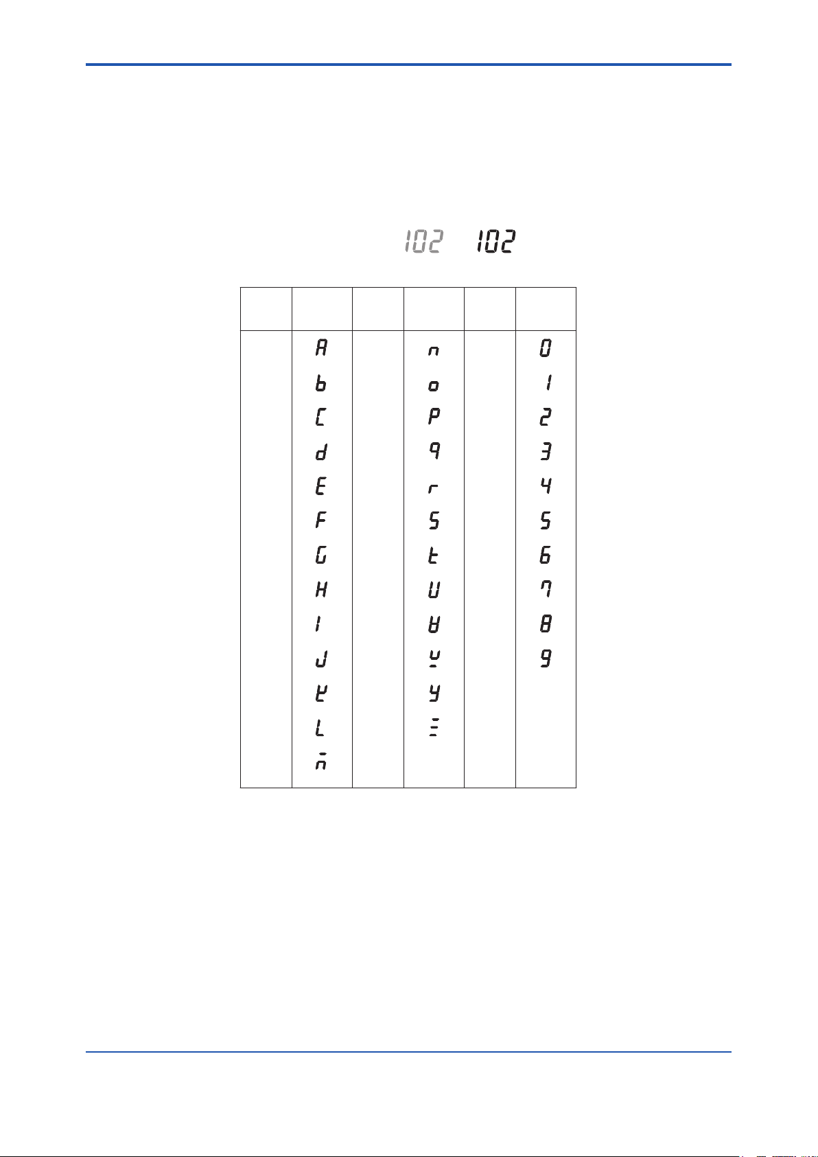
Alphanumerics Alphanumerics AlphanumericsLED Display LED Display LED Display
Z
Y
Special descriptions in this manual
This manual indicates operation keys, displays and drawings on the product as follows:
v
• Operation keys, displays on the panel
Enclosed in [ ]. (Ex. "MODE" key)
(Ex. message display → "BASE")
(Ex. data display → "102" lit, "102" ashing)
• Drawing for ashing
Indicated by gray characters (Flashing) (lit)
• Displays on the LCD display panel
IM 11M12A01-04E
Page 7

vi
IM 11M12A01-04E
<Introduction>
NOTICE
• Specication check
When the instrument arrives, unpack the package with care and check that the instrument has not
been damaged during transportation. In addition, please check that the specication matches the
order, and required accessories are not missing. Specications can be checked by the model codes
on the nameplate. Refer to Chapter 2 specications for the list of model codes.
• Details on operation parameters
When the EXAxt ZR Integrated type Zirconia Oxygen Analyzer arrives at the user site, it will operate
based on the operation parameters (initial data) set before shipping from the factory.
Ensure that the initial data is suitable for the operation conditions before conducting analysis.
Where necessary, set the instrument parameters for appropriate operation. For details on setting data,
refer to Chapters 7 to 10.
When user changes the operation parameter, it is recommended to note down the changed setting
data.
• How to dispose the batteries:
This is an explanation about the new EU Battery Directive (DIRECTIVE 2006/66/EC). This directive is
only valid in the EU.
Batteries are included in this product. Batteries incorporated into this product cannot be removed by
yourself. Dispose them together with this product.
When you dispose this product in the EU, contact your local Yokogawa Europe B.V.ofce. Do not
dispose them as domestic household waste.
Battery type: silver oxide battery
Notice:
The symbol (see above) means they shall be sorted out and collected as ordained in ANNEX II in
DIRECTIVE 2006/66/EC
Page 8

After-Sales Warranty
Do not modify the product.
During the warranty period, for repair under warranty carry or send the product to the local sales
representative or service ofce. Yokogawa will replace or repair any damaged parts and return
the product to you.
Before returning a product for repair under warranty, provide us with the model name and serial
number and a description of the problem. Any diagrams or data explaining the problem would
also be appreciated.
If we replace the product with a new one, we won’t provide you with a repair report.
Yokogawa warrants the product for the period stated in the pre-purchase quotation. Yokogawa
shall conduct dened warranty service based on its standard. When the customer site is located
outside of the service area, a fee for dispatching the maintenance engineer will be charged to the
customer.
In the following cases, customer will be charged repair fee regardless of warranty period.
• Failure of components which are out of scope of warranty stated in instruction manual.
• Failure caused by usage of software, hardware or auxiliary equipment, which Yokogawa Elec-
tric did not supply.
<Introduction>
vii
• Failure due to improper or insufcient maintenance by user.
• Failure due to modication, misuse or outside-of-specications operation which Yokogawa
does not authorize.
• Failure due to power supply (voltage, frequency) being outside specications or abnormal.
• Failure caused by any usage out of scope of recommended usage.
• Any damage from re, earthquake, storms and oods, lightning, disturbances, riots, warfare,
radiation and other natural changes.
Yokogawa does not warrant conformance with the specic application at the user site. Yokogawa
will not bear direct/indirect responsibility for damage due to a specic application.
Yokogawa Electric will not bear responsibility when the user congures the product into systems
or resells the product.
Maintenance service and supplying repair parts will be covered for ve years after the production
ends. For repair for this product, please contact the nearest sales ofce described in this instruc-
tion manual.
IM 11M12A01-04E
Page 9

viii
<Introduction>
IM 11M12A01-04E
Page 10

<CONTENTS>
Model ZR202G
Integrated type Zirconia Oxygen Analyzer
IM 11M12A01-04E 7th Edition
CONTENTS
Introduction ..............................................................................................................i
For the safe use of this equipment .............................................................................. iii
NOTICE ........................................................................................................................... vi
After-Sales Warranty .................................................................................................... vii
1. Overview .................................................................................................... 1-1
1.1 <EXAxtZR>SystemConguration ............................................................... 1-1
1.1.1 System 1 ............................................................................................
1.1.2 System 2 ............................................................................................
1.1.3 System 3 ............................................................................................
1.2 < EXAxt ZR > System Components ................................................................
1.2.1 System Components .........................................................................
1.2.2 Oxygen Analyzer and Accessories ....................................................
Toc-1
1-1
1-2
1-3
1-4
1-4
1-4
2. Specications ........................................................................................... 2-1
2.1 GeneralSpecications ..................................................................................... 2-1
2.1.1 StandardSpecications .....................................................................
2.1.2 ZR202G Integrated type Zirconia Oxygen Analyzer ..........................
2.1.3 ZO21R Probe Protector .....................................................................
2.2 ZA8F Flow Setting Unit and ZR20H Automatic Calibration Unit ................
2.2.1 ZA8F Flow Setting Unit ....................................................................
2.2.2 ZR20H Automatic Calibration Unit ...................................................
2.3 ZO21S Standard Gas Unit ..............................................................................
2.4 Other Equipment .............................................................................................
2.4.1 Dust Filter for Oxygen Analyzer (part no. K9471UA) .......................
2.4.2 Dust Guard Protector (part no. K9471UC) ......................................
2.4.3 Stop Valve (part no. L9852CB or G7016XH) ...................................
2.4.4 Check Valve (part no. K9292DN or K9292DS) ................................
2.4.5 Air Set ...............................................................................................
2.4.6 Zero Gas Cylinder (part no. G7001ZC) ...........................................
2.4.7 Pressure Regulator (G7013XF or G7014XF) for Gas Cylinder .......
2.4.8 Case Assembly (E7044KF) for Calibration gas Cylinder .................
2.4.9 ZR202A Heater Assembly ...............................................................
2-1
2-2
2-9
2-10
2-10
2-12
2-14
2-15
2-15
2-15
2-16
2-16
2-17
2-18
2-18
2-19
2-19
IM 11M12A01-04E
Page 11

Toc-2
<CONTENTS>
3. Installation ................................................................................................. 3-1
3.1 Installation of ZR202G Zirconia Oxygen Analyzer ........................................3-1
3.1.1 Installation Location ...........................................................................
3.1.2 Probe Insertion Hole ..........................................................................
3.1.3 Installation of the Probe .....................................................................
3.1.4 Installation of the Dust Filter (K9471UA), Dust Guard Protector
(K9471UC) Probe Protector (ZO21R) ...............................................3-3
3.2 Installation of ZA8F Flow Setting Unit ............................................................
3.2.1 Installation Location ...........................................................................
3.2.2 Mounting of ZA8F Flow Setting Unit ..................................................
3.3 Installation of ZR20H Automatic Calibration Unit .........................................
3.3.1 Installation Location ...........................................................................
3.3.2 Mounting of ZR20H Automatic Calibration Unit .................................
3.4 Installation of the Case Assembly (E7044KF) for
Calibration Gas Cylinder ..................................................................................3-9
3.4.1 Installation Location ...........................................................................
3.4.2 Mounting ............................................................................................
3.5 Insulation Resistance Test .............................................................................
3-1
3-2
3-2
3-5
3-5
3-6
3-7
3-7
3-7
3-9
3-9
3-10
4. Piping ......................................................................................................... 4-1
4.1 Piping for System 1 ...........................................................................................4-1
4.1.1 Piping Parts for System 1 ..................................................................
4.1.2 Piping for the Calibration Gas ............................................................
4.1.3 Piping for the Reference Gas
4.2 Piping for System 2 ...........................................................................................
4.2.1 Piping Parts for System 2 ..................................................................
4.2.2 Piping for the Calibration Gas ............................................................
4.2.3 Piping for the Reference Gas
4.3 Piping for System 3 ...........................................................................................
4.4 Piping for the Oxygen Analyzer with Pressure Compensation ...................
4.4.1 Piping Parts for Oxygen Analyzer with Pressure Compensation ......
4.4.2 Piping for the Calibration Gas ............................................................
4.4.3 Piping for the Reference Gas
.............................................................4-2
.............................................................4-4
.............................................................4-8
4-2
4-2
4-3
4-3
4-3
4-4
4-6
4-8
4-8
5. Wiring ......................................................................................................... 5-1
5.1 General ...............................................................................................................5-1
5.1.1 Terminals for the External Wiring .......................................................
5.1.2 Wiring .................................................................................................
5.1.3 Mounting of Cable Gland ...................................................................
5.2 Wiring for Analog Output .................................................................................
5.2.1 Cable Specications ..........................................................................
5.2.2 Wiring Procedure ...............................................................................
5-2
5-2
5-3
5-3
5-3
5-3
IM 11M12A01-04E
Page 12

<CONTENTS>
5.3 Wiring Power and Ground Terminals .............................................................5-4
5.3.1 Wiring for Power Line .........................................................................
5.3.2 Wiring for Ground Terminals ..............................................................
5.4 Wiring for Contact Output ................................................................................
5.4.1 Cable Specications ..........................................................................
5.4.2 Wiring Procedure ...............................................................................
5.5 Wiring for Contact Input ...................................................................................
5.5.1 Cable Specications ..........................................................................
5.5.2 Wiring Procedure ...............................................................................
Toc-3
5-4
5-4
5-5
5-5
5-5
5-5
5-5
5-6
6. Components ............................................................................................. 6-1
6.1 ZR202G Zirconia Oxygen Analyzer .................................................................6-1
6.1.1 Integrated type Zirconia Oxygen Analyzer ........................................
6.2 ZA8F Flow Setting Unit, ZR20H Automatic Calibration Unit ........................
6-1
6-2
7. Startup ....................................................................................................... 7-1
7.1 Checking Piping and Wiring Connections .....................................................7-2
7.2 Valve Setup ........................................................................................................
7.3 Supplying Power to Converter ........................................................................
7.4 Operation of Infrared Switch ...........................................................................
7.4.1 Display and Switches .........................................................................
7.4.2 Display Conguration .........................................................................
7.4.3 Entering Parameter Code Selection Display .....................................
7.4.4 Selecting Parameter Codes ...............................................................
7.4.5 Changing Set Values .........................................................................
7.5 Conrmation of Equipment Type Setting .......................................................
7.6 Selection of Measurement Gas .......................................................................
7.7 Output Range Setting .......................................................................................
7.7.1 Minimum Current (4 mA) and Maximum Current (20 mA) Settings ..
7.8 Checking Current Loop ..................................................................................
7.9 Checking Contact I/O ......................................................................................
7.9.1 Contact Output Check .....................................................................
7.9.2 Checking Calibration Contact Output ..............................................
7.9.3 Checking Input Contacts ..................................................................
7.10 Calibration .......................................................................................................
7.10.1 Calibration Setup .............................................................................
7.10.2 Manual Calibration ...........................................................................
7-2
7-2
7-3
7-3
7-4
7-5
7-6
7-6
7-8
7-9
7-9
7-9
7-11
7-11
7-12
7-13
7-14
7-15
7-15
7-17
IM 11M12A01-04E
Page 13

Toc-4
<CONTENTS>
8. Detailed Data Setting ............................................................................... 8-1
8.1 Setting Display Item ..........................................................................................8-1
8.2 Current Output Setting .....................................................................................
8.2.1 Setting Minimum Oxygen Concentration ( at 4 mA) and Maximum
Oxygen Concentration ( at 20 mA) ....................................................8-2
8.2.2 Entering Output Damping Constants .................................................
8.2.3 Selection of Output Mode ..................................................................
8.2.4 Default Values ....................................................................................
8.3 Output Hold Setting ..........................................................................................
8.3.1 Denition of Equipment Status ..........................................................
8.3.2 Preference Order of Output Hold Value .............................................
8.3.3 Output Hold Setting ............................................................................
8.3.4 Default Values ....................................................................................
8.4 Setting Oxygen Concentration Alarms
8.4.1 Alarm Values ......................................................................................
8.4.2 Alarm Output Actions .........................................................................
8.4.3 Alarm Setting
8.4.4 Default Values ....................................................................................
8.5 Output Contact Setup .......................................................................................
8.5.1 Output Contact ...................................................................................
8.5.2 Setting Output Contact ......................................................................
8.5.3 Default Values ..................................................................................
8.6 Input Contact Settings ....................................................................................
8.6.1 Setting Input Contact .......................................................................
8.6.2 Default Values ..................................................................................
8.7 Other Settings .................................................................................................
8.7.1 Setting the Date-and-Time ...............................................................
8.7.2 Setting Periods over which Average Values are Calculated and Periods
over which Maximum and Minimum Values Are Monitored.............8-13
8.7.3 Setting Fuels ....................................................................................
8.7.4 Setting Purging ................................................................................
......................................................................................8-7
...........................................................8-6
8-1
8-2
8-2
8-2
8-3
8-3
8-5
8-5
8-5
8-6
8-6
8-8
8-8
8-8
8-9
8-10
8-11
8-11
8-11
8-12
8-12
8-14
8-18
9. Calibration ................................................................................................. 9-1
IM 11M12A01-04E
9.1 Calibration Briefs ..............................................................................................9-1
9.1.1 Principle of Measurement ..................................................................
9.1.2 Calibration Gas ..................................................................................
9.1.3 Compensation ....................................................................................
9.1.4 Characteristic Data from a Sensor Measured During Calibration .....
9.2 Calibration Procedures ....................................................................................
9.2.1 Calibration Setting ..............................................................................
9.2.2 Calibration ..........................................................................................
9-1
9-2
9-2
9-4
9-5
9-5
9-8
Page 14

<CONTENTS>
Toc-5
10. Other Functions ...................................................................................... 10-1
10.1 Detailed Display ..............................................................................................10-1
10.1.1 Air Ratio
10.1.2 Cell Temperature ..............................................................................
10.1.3 C. J. Temperature
10.1.4 Amount of Water Vapor in Exhaust Gas ..........................................
10.1.5 Cell Voltage ......................................................................................
10.1.6 Thermocouple Voltage .....................................................................
10.1.7 Cold Junction Voltage ......................................................................
10.1.8 Current Output .................................................................................
10.1.9 Response Time ................................................................................
10.1.10 Cell’s Internal Resistance ...............................................................
10.1.11 Robustness of a Cell .......................................................................
10.1.12 Heater On-Time Ratio .....................................................................
10.1.13 Oxygen Concentration (with time constant) ....................................
10.1.14 Maximum Oxygen Concentration ...................................................
10.1.15 Minimum Oxygen Concentration ....................................................
10.1.16 Average Oxygen Concentration ......................................................
10.1.17 Span and Zero Correction Ratios ...................................................
10.1.18 History of Calibration Time ..............................................................
10.1.19 Time .................................................................................................
10.1.20 Software Revision ...........................................................................
10.2 Operational Data Initialization ......................................................................
10.3 Initialization Procedure ..................................................................................
10.4 Reset .................................................................................................................
10.5 Handling of the ZO21S Standard Gas Unit .................................................
10.5.1 Standard Gas Unit Component Identication ................................
10.5.2 Installing Gas Cylinders .................................................................
10.5.3 Calibration Gas Flow ......................................................................
10.6 Methods of Operating Valves in the ZA8F Flow Setting Unit ...................
10.6.1 Preparation Before Calibration ......................................................
10.6.2 Operating the Span Gas Flow Setting Valve .................................
10.6.3 Operating the Zero Gas Flow Setting Valve ..................................
10.6.4 Treatment After Calibration ............................................................
............................................................................................10-3
10-3
.............................................................................10-3
10-3
10-4
10-4
10-4
10-4
10-5
10-5
10-5
10-6
10-6
10-6
10-6
10-6
10-6
10-7
10-7
10-7
10-7
10-8
10-9
10-16
10-16
10-16
10-17
10-19
10-19
10-19
10-19
10-20
11. Inspection and Maintenance ................................................................. 11-1
11.1 Inspection and Maintenance of the Detector ............................................... 11-1
11.1.1 Cleaning the Calibration Gas Tube ..................................................
11.1.2 Replacing the Sensor Assembly ......................................................
11.1.3 Replacement of the Heater Assembly .............................................
11.1.4 Replacement of Dust Filter ..............................................................
11.1.5 Replacement of O-ring .....................................................................
11.1.6 Stopping and Re-starting Operation ................................................
11-1
11-2
11-4
11-6
11-6
11-6
IM 11M12A01-04E
Page 15

Toc-6
<CONTENTS>
11.2 Inspection and Maintenance of the Converter ............................................ 11-8
11.2.1 Replacing Fuses ..............................................................................
11.3 Replacement of Flowmeter for ZR20H Automatic Calibration Unit ........
11-8
11-10
12. Troubleshooting ..................................................................................... 12-1
12.1 Displays and Measures to Take When Errors Occur .................................. 12-1
12.1.1 What is an Error? .............................................................................
12.1.2 Measures to Take When an Error Occurs .......................................
12.2 Displays and Measures to Take When Alarms are Generated ...................
12.2.1 What is an Alarm? ............................................................................
12.3 Measures When Measured Value Shows an Error ......................................
12.3.1 Measured Value Higher Than True Value ........................................
12.3.2 Measured Value Lower Than True Value ......................................
12.3.3 Measurements Sometimes Show Abnormal Values .....................
12-1
12-2
12-4
12-4
12-9
12-9
12-10
12-10
Customer Maintenance Parts List ........................................CMPL 11M12A01- 04E
Customer Maintenance Parts List ........................................CMPL 11M12A01-12E
Customer Maintenance Parts List ...........................................CMPL 11M3D1- 01E
Revision Information ...............................................................................................i
IM 11M12A01-04E
Page 16
<1.Overview>
~
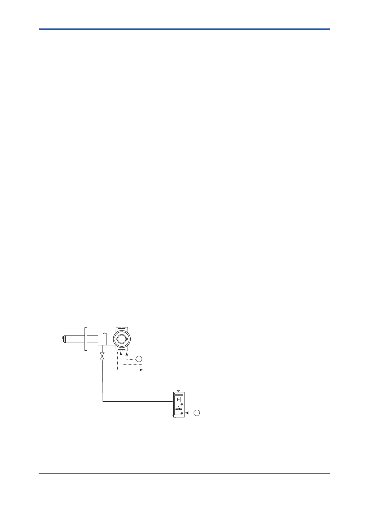
ZR202G Integrated type Zirconia Oxygen Analyzer
ZO21S Standard gas unit
Stop valve
Calibration gas
F1.1E.ai
~
100 to 240 V AC
100/110/115
200/220/240 V AC
Contact input
Analog output, contact output
Digital output (HART)
1. Overview
The EXAxt ZR Integrated type Zirconia Oxygen Analyzer is used to monitor and control the oxygen
concentration in combustion gases, in boilers and industrial furnaces, for wide application in industries
which consume considerable energy-such as steel, electric power, oil and petrochemical, ceramics,
pulp and paper, food, or textiles, as well as incinerators and medium/small boilers. It can help conserve
energy in these industries. The EXAxt ZR also contributes to preservation of the earth’s environment
in preventing global warming and air pollution by controlling complete combustion to reduce CO2, SOx
and NOx.
The EXAxt ZR Integrated type Zirconia Oxygen Analyzer integrates both probe and converter. The
analyzers need not use a sampling device, and allow direct installation of the probe in the wall of a ue
or furnace to measure the concentration of oxygen in the stack gas of the temperature up to 700°C.
The probe uses a high-reliability Zirconia sensor and a heater assembly that can be replaced on site.
The analyzer is equipped with three infrared switches, which enable the user to operate the equipment
without opening the cover on site. Analyzer calibration can also be fully automated and the automatic
calibration unit is provided. Choose the equipment which best suits your needs so that an optimal
combustion control system can be obtained.
Some examples of typical system conguration are illustrated below:
1-1
1.1 <EXAxtZR>SystemConguration
The system configuration should be determined by the conditions; e.g. whether the calibration is to
be automated, and whether flammable gas is present and requires safety precautions. The system
conguration can be classied into three basic patterns as follows:
1.1.1 System 1
This is the simplest system consisting of an integrated type analyzer. This system can be implemented
for monitoring oxygen concentration in the combustion gases boiler. No piping is required for the
reference gas (air) which is fed in at the installation site. The ZO21S standard gas unit is used for
calibration.
Zero gas from this unit and span gas (air) is sent to the probe through a tube which is connected
during calibration.
Figure1.1 ExampleofSystem1
IM 11M12A01-04E
Page 17
<1. Overview>
1-2
IM 11M12A01-04E
CAUTION
~
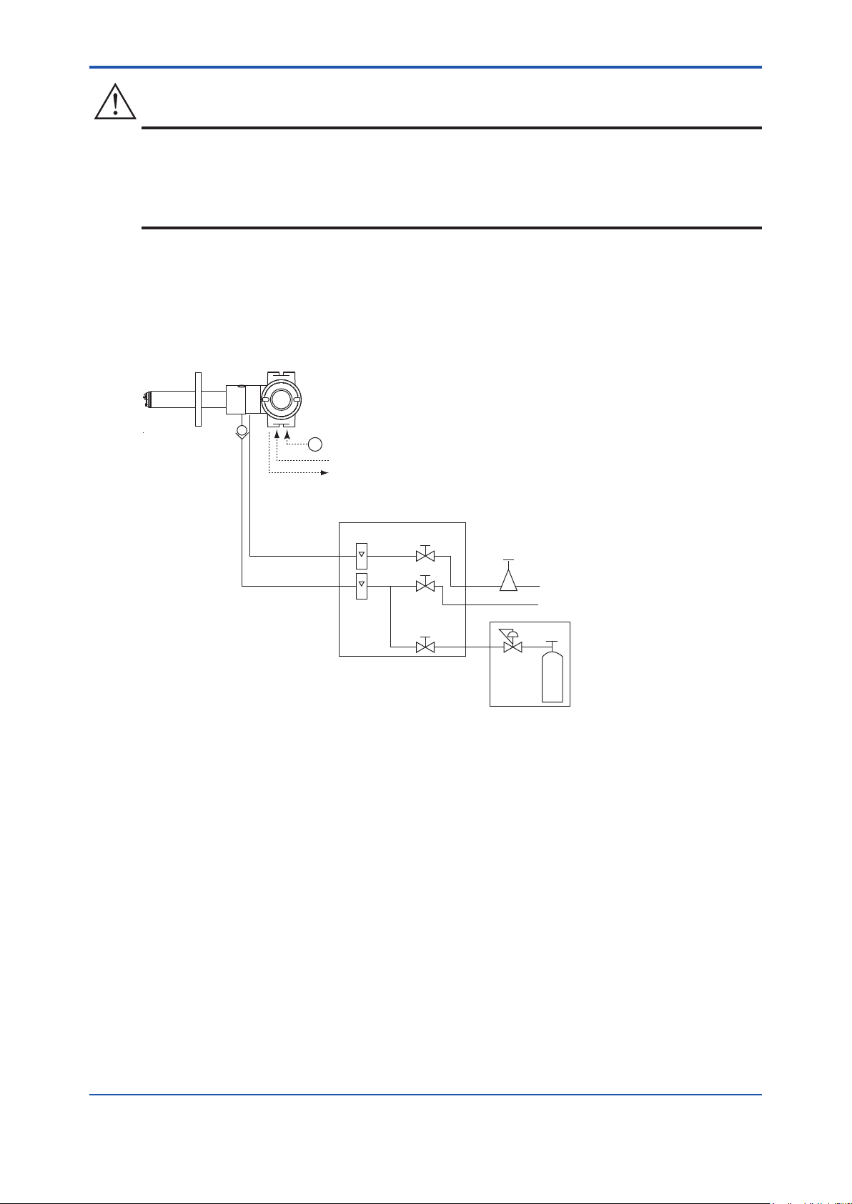
ZR202G Integrated type Zirconia Oxygen Analyzer
F1.2E.ai
ZA8F flow setting unit
Reference gas
Calibration gas
Needle
valve
Flowmeter
Instrument air
Air Set
Calibration
gas pressure
regulator
Zero gas cylinder
Calibration gas unit case
Stop valve
or
Check valve
Span gas(Same as Zero gas calibration)
100 to 240 V AC
Contact input
Analog output, contact output
Digital output (HART)
• As this system uses ambient air for the reference gas, measuring accuracy will be affected by
the installation location.
• A stop valve should be connected to the calibration gas inlet of the equipment. The valve should
be fully closed unless calibration is in progress.
1.1.2 System 2
This system is for monitoring and controlling oxygen concentration in the combustion gases of a
large-size boiler or heating furnace. Instrument air (clean and dry air of oxygen concentration 21%)
is used as the reference gas and the span gas for calibration. Zero gas is fed from a cylinder during
calibration. The gas ow is controlled by the ZA8F ow setting unit (for manual valve operation).
Figure 1.2 Example of System 2
Page 18
<1.Overview>
~
100 to 240 V AC
Automatic calibration unit
Reference gas
Calibration gas (Zero)
Contact input
Analog output, contact output
Digital output (HART)
Air Set
Instrument air
Calibration gas unit case
Calibration
gas pressure
regulator
Zero gas cylinder
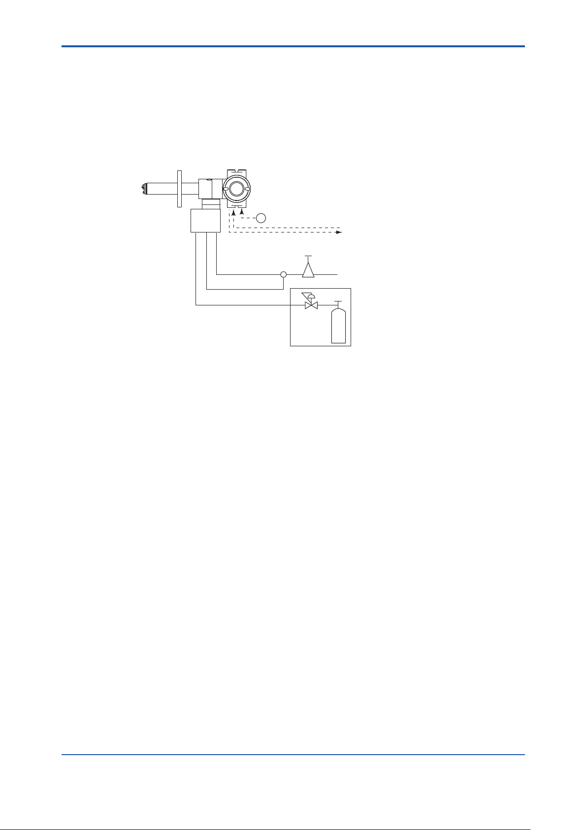
ZR202G Integrated type Zirconia Oxygen Analyzer
with automatic calibration unit (ZR202G-□-□-□-A-□-□-□-□-A)
F1.3E.ai
Span gas
ZR20H
*3
Note:
The installation temperature limits range for integrated type analyzer is -20 to 55°C.
*2
*1
1.1.3 System 3
This example, System 3, represents typical applications in large boilers and heating furnaces, where
is a need to monitor and control oxygen concentration. The reference gas and calibration-time span
gas are (clean, dry) instrument air. Zero gas is supplied from a gas cylinder.
System 3 uses the ZR20H automatic calibration unit, with auto-switching of the calibration gas.
A “combustible gas detected” contact input turns off power to the heater. There’s also contact output
from the converter that can be used to operate a purge gas valve to supply air to the sensor.
1-3
*1 Shield cable:
Use shielded signal cables, and connect the shields to the FG terminal of the converter.
*2 Select the desired probe from the Probe Conguration table on page 1-4.
*3 When a zirconia oxygen analyzer is used, 100% N
Use approx. 1 vol% O2 gas (N2-based).
gas cannot be used as the zero gas.
2
Figure 1.3 Example of System 3
IM 11M12A01-04E
Page 19
1-4
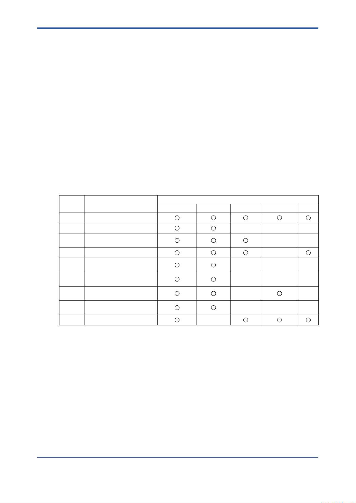
System Components
ZR202G Integrated type Zirconia Oxygen Analyzers
ZO21R Probe Protector for Zirconia Oxygen Analyzers
K9471UA Dust Filter for Oxygen Analyzer
ZO21S Standard Gas Unit
ZA8F Flow Setting Unit for manual calibration
ZR20H Automatic Calibration Unit for Integrated type Analyzer
L9852CB, G7016XH Stop Valve for Calibration gas line
K9292DN,K9292DS Check Valve for Calibration gas line
G7003XF/K9473XK, G7004XF/K9473XG Air Set
G7001ZC Zero gas Cylinder
G7013XF, G7014XF Pressure Regulator for Gas Cylinder
E7044KF Case Assembly for Calibration gas Cylinder
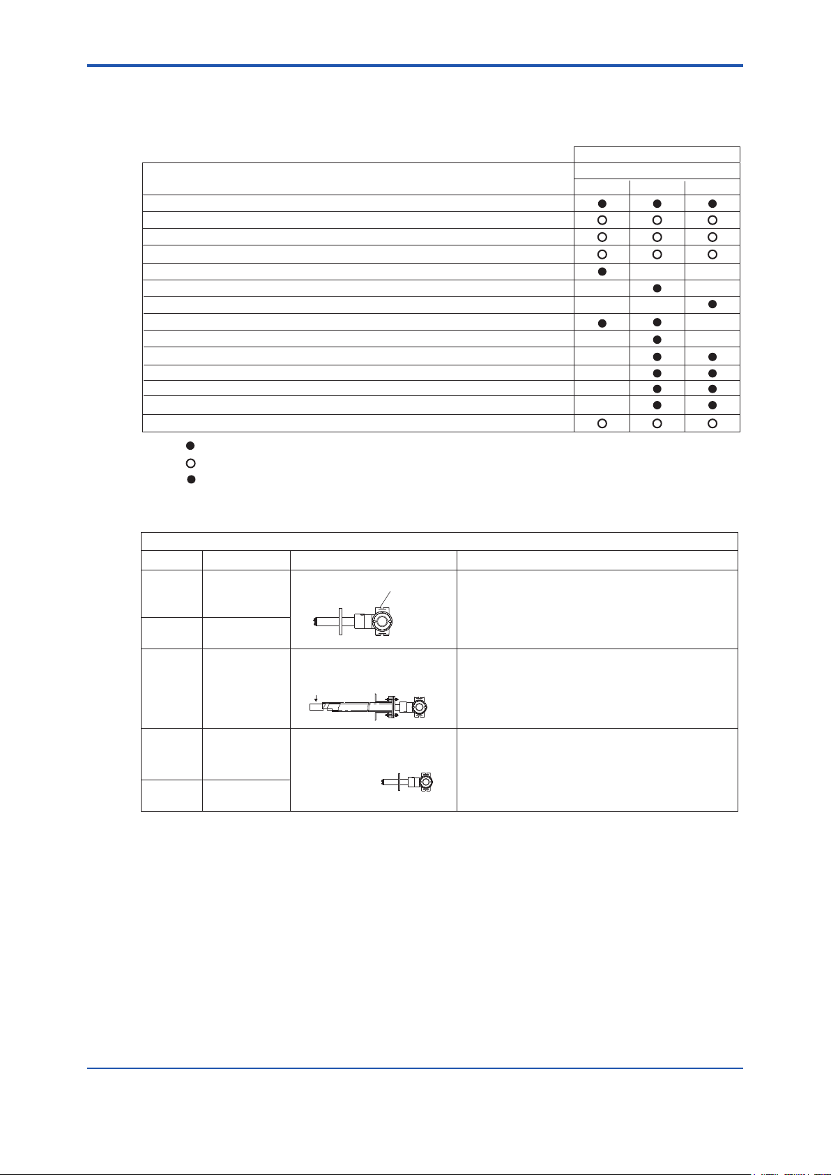
Integrated type
System configuration
Example 3Example 1
Example 2
( )
( )
T1.1.ai
: Items required for the above system example
: To be selected depending on each application. For details, refer to corresponding chapter.
: Select either
( )
ZR202A Heater Assembly (Spare Parts for ZR202G)
K9471UC Dust Guard Protector
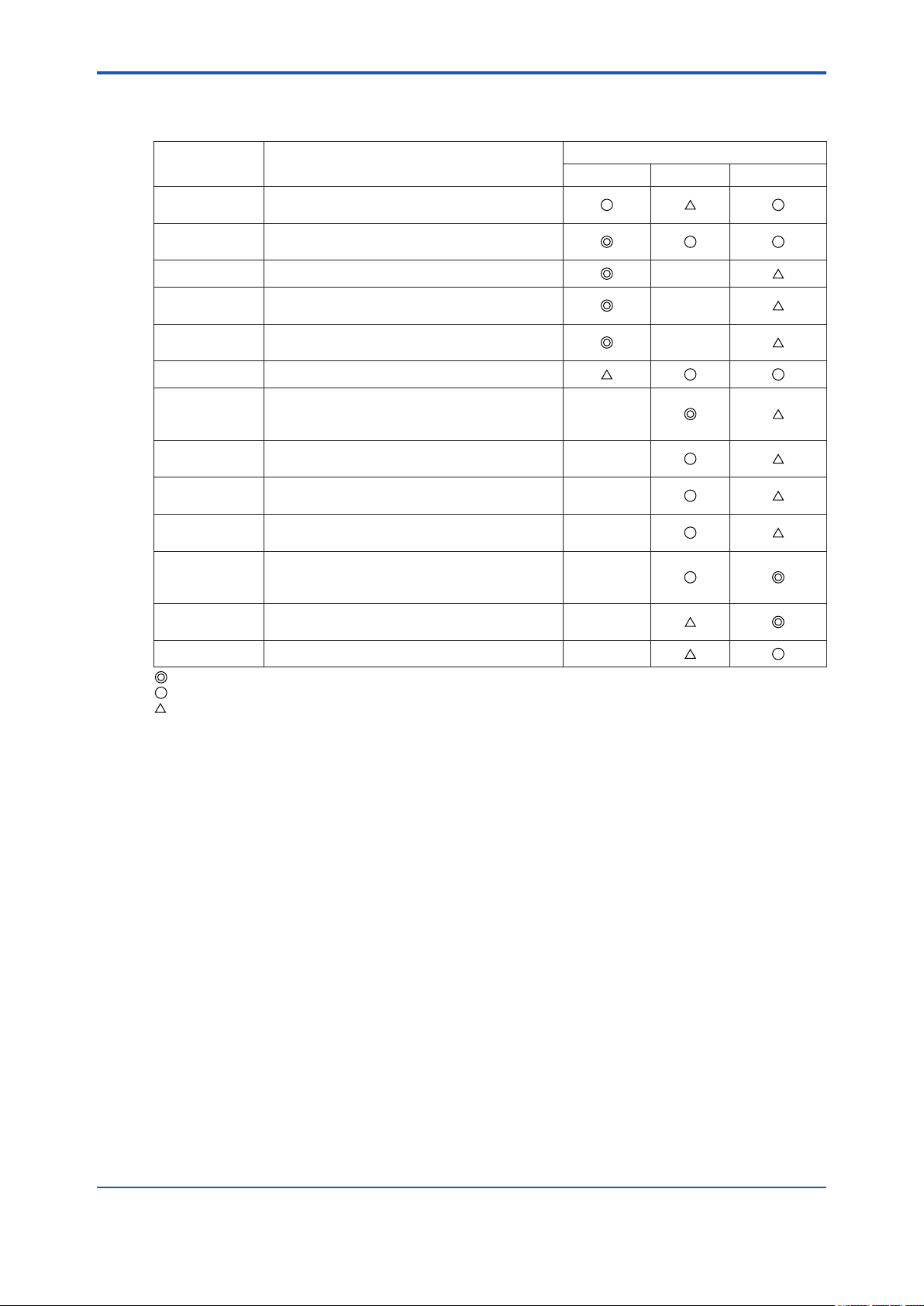
F1.4E.ai
Detector
(ZR202G)
Detector
(ZR202G)
Detector(ZR202G)
Probe Protector
(ZO21R)
Dust Filter
(K9471UA)
or
Dust Guard
Protector
(K9471UC)
+
Sample gas temperature 0 to 700°C
Mounting
Insertion length
General-use Probe
Application
Horizontal
to
vertical
Horizontal
to
vertical
Horizontal
to
vertical
Vertical
Vertical
0.4
to
2 m
0.4
to
2 m
2.5 m
or more
3 m
or less
2.5 m
or more
• Boiler
• Heating furnace
• For pulverized coal boiler with gas flow velocity
10 m/sec or more
• Cement Kiln
• Black liquid recovery boiler
• Cement Kiln
Gas Flow
Sample inlet
<1. Overview>
1.2 < EXAxt ZR > System Components
1.2.1 System Components
1.2.2 Oxygen Analyzer and Accessories
IM 11M12A01-04E
Page 20

<2. Specications>
2. Specications
This chapter describes the specications for the following:
ZR202G General-use Integrated type Zirconia Oxygen Analyzer (See Section 2.1.2)
ZO21R-L Probe Protector (See Section 2.1.3)
ZA8F Flow Setting Unit (See Section 2.2.1)
ZR20H Automatic Calibration Unit (See Section 2.2.2)
ZO21S Standard Gas Unit (See Section 2.3)
K9471UA Dust Filter for Oxygen Analyzer (See Section 2.4)
2.1 General Specications
2.1.1 Standard Specications
Measured Object: Oxygen concentration in combustion exhaust gas and mixed gas (excluding
inammable gases). May not be applicable corrosive gas such as ammonia,
chlorine is present-check with YOKOGAWA.)
2-1
Measured System: Zirconia system
Oxygen Concentration: 0.01 to 100 vol% O
Output Signal: 4 to 20 mA DC (maximum load resistance 550Ω)
Measurement Range: Any setting in the range of 0 to 5 through 0 to 100 vol% O
partial range
Digital Communication (HART): 250 to 550Ω, depending on number of eld devices connected to the
loop (multi-drop mode).
Note: HART is a registered trademark of the HART Communication Foundation.
Display Range: 0 to 100 vol% O
Warm-up Time: Approx. 20 min.
Repeatability: (Excluding the case where the reference gas is by natural convection)
± 0.5% Maximum value of set range; less than 0 to 25 vol% O2 range
± 1 % Maximum value of set range; 0 to 25 vol%
Linearity: (Excluding standard gas tolerance)
(Excluding the case where the reference gas is by natural convection)
(Use oxygen of known concentration (with in the measuring range) as the
zero and span calibration gases.)
± 1% Maximum value of set range; less than 0 to 25 vol% O2 range
± 3% Maximum value of set range; 0 to 25 vol% O2 or more and less than 0
± 5% Maximum value of set range; 0 to 50 vol %O2 or more and up to 0 to
2
(in 1 vol%O2), or
2
2
O2 or more and up to 0 to
100 vol% O2 range
(Sample gas pressure: within ± 4.9 kPa)
to 50 vol% O2 range
(Sample gas pressure: within ± 0.49 kPa)
100 vol% O2 range
(Sample gas pressure: within ± 0.49 kPa)
IM 11M12A01-04E
Page 21

<2. Specications>
2-2
IM 11M12A01-04E
Drift: (Excluding the rst two weeks in use)
(Excluding the case where the reference gas is by natural convection.)
Both zero and span ± 2% Maximum value of set range/month
Response Time: Response of 90% within 5 seconds. (Measured after gas is introduced from
calibration gas inlet and analog output starts changing.)
2.1.2 ZR202G Integrated type Zirconia Oxygen Analyzer
Can be operated in the eld without opening the cover using optical switches.
Display: 6-digit LCD
Switch: Three optical switches
Output Signal: 4 to 20 mA DC, one point (maximum load resistance 550 Ω)
Digital Communication (HART): 250 to 550 Ω, depending on quantity of eld devices connected to the
loop (multi-drop mode).
Note: HART is a registered trademark of the HART Communication Foundation.
Contact Output Signal: Two points (one is fail-safe, normally open)
Contact Input Signal: Two points
Sample Gas Temperature: 0 to 700°C
It is necessary to mount the cell using Inconel cell-bolts when the
temperature measures more than 600°C.
High-temperature service ― greater than 700°C ― is not available.
Sample Gas Pressure: -5 to +250 kPa (When the pressure in the furnace exceeds 3 kPa, it is
recommended to compensate the pressure. When the pressure in the
furnace exceeds 5 kPa, you must perform pressure compensation.)
No pressure uctuation in the furnace be allowed.
Note: When the detector is used in conjunction with a check valve and the ZA8F Flow Setting Unit, the maximum pressure of sample
gas is 150 kPa. When with a check valve and the ZR20H Automatic Calibration Unit, it is 200 kPa. If the pressure of your sample
gas exceeds these limits, consult with Yokogawa.
Probe Length: 0.4, 0.7, 1.0, 1.5, 2.0, 2.5, 3.0 m
Probe Material: SUS 316 (JIS)
Ambient Temperature: -20 to +55°C (- 5 to +70°C on the case surface)
Storage Temperature: -30 to +70°C
Humidity Range: 0 to 95%RH (non-condensing)
Installation Altitude: 2000 m or less
Category based on IEC 1010: II (Note)
Pollution degree based on IEC 1010: 2 (Note)
Note: Installation category, called over-voltage category, species impulse withstand voltage. Category II is for electrical equipment.
Pollution degree indicates the degree of existence of solid, liquid, gas or other inclusions which may reduce dielectric strength.
Degree 2 is the normal indoor environment.
Power Supply Voltage: Ratings; 100 to 240 V AC
Acceptable range; 85 to 264 V AC
Power Supply Frequency: Ratings; 50/60 Hz
Acceptable range; 45 to 66 Hz
Power Consumption: Max. 300 W, approx. 100 W for ordinary use.
Page 22

<2. Specications>
CAUTION
Safety and EMC conforming standards
Safety: EN61010-1, CSA C22.2 No.61010-1,
EMC: EN 61326 Class A,
CISPR 11
KC Marking: Korea Electromagnetic Conformity Standard
This instrument is a Class A product, and it is designed for use in the industrial environment. Please
use this instrument in the industrial environment only.
Reference Gas System: Natural Convection, Instrument Air, Pressure Compensation
Instrument Air System (excluding Natural Convection):
Pressure; 200 kPa + the pressure inside the furnace (It is recommended
to use air which is dehumidied by cooling to dew point -20°C or
less, and dust or oil mist are removed.)
Consumption; Approx. 1Nl/min
EN 55011 Class A Group 1, EN 61000-3-2, AS/NZS
UL61010-1
2-3
Material in Contact with Gas: SUS 316 (JIS), Zirconia, SUS 304 (JIS) (ange), Hastelloy B, (Inconel
600, 601)
Construction: Heater and thermocouple replaceable construction. Non explosion-proof JIS
C0920 / equivalent to IP44D. Equivalent to NEMA 4X/IP66 (Achieved when
the cable entry is completely sealed with a cable gland in the recirculation
pressure compensated version.)
Gas Connection: Rc 1/4 or 1/4 FNPT
Wiring Connection: G1/2, Pg13.5, M20 by 1.5mm, 1/2 NPT select one type (4 pieces)
Installation: Flange mounting
Probe Mounting Angle: Horizontal to vertically downward.
When the probe insertion length is 2 m or less, installing at angles from
horizontal to vertically downward is available.
When the probe insertion length is 2.5m or more, mount vertically downward
(within ± 5°), and if installing at angles from horizontal to vertically downward
(within ± 5°), use a probe protector.
Case: Aluminum alloy
Paint Color: Cover; Mint green (Munsell 5.6BG3.3/2.9)
Case; Mint green (Munsell 5.6BG3.3/2.9)
Finish: Polyurethane corrosion-resistance coating
Insertion length of 0.4m: approx. 8 kg (JIS 5K 65) / approx. 13 kg (ANSI 150 4)
Insertion length of 1.0m: approx. 10 kg (JIS 5K 65) / approx. 15 kg (ANSI 150 4)
Insertion length of 1.5m: approx. 12 kg (JIS 5K 65) / approx. 17 kg (ANSI 150 4)
Insertion length of 2.0m: approx. 14 kg (JIS 5K 65) / approx. 19 kg (ANSI 150 4)
Insertion length of 3.0m: approx. 17 kg (JIS 5K 65) / approx. 22 kg (ANSI 150 4)
Weight:
IM 11M12A01-04E
Page 23

<2. Specications>
2-4
IM 11M12A01-04E
Functions
Display Function: Displays values of the measured oxygen concentration, etc.
Alarm, Error Display: Displays alarms such as “AL-06” or errors such as “Err-01” when any such
status occurs.
Calibration Functions: Auto-calibration; Requires the Automatic Calibration Unit. It calibrates
Maintenance Functions: Can operate updated data settings in daily operation and checking. Display
Setup Functions: Initial settings suit for the plant conditions when installing the converter.
Display and setting content:
Display Related Items: Oxygen concentration (vol% O2), Output current value (mA), air ratio,
automatically at specied intervals.
Semi-auto Calibration; Requires the Automatic Calibration Unit. Input
calibration start signal by optical switch or contact, then it calibrates
automatically afterwards.
Manual Calibration; Calibration with opening/closing the valve of calibration
gas in operation interactively with the optical switch.
data settings, calibration data settings, test settings (current output loop
check, input/output contact check).
Current output data settings, alarm data settings, contact data settings, other
settings.
moisture quantity (in hot gases) (vol% H2O), Cell temperature (°C ),
thermocouple reference junction temperature (°C ), maximum/minimum/
average oxygen concentration (vol% O2), cell e.m.f. (mV), cell internal
resistance (Ω), cell condition (in four grades), heater on-time rate (%),
calibration record (ten times), time (year/month/day/hour/minute)
Calibration Setting Items: Span gas concentration (vol% O2), zero gas concentration (vol%O2),
calibration mode (auto, semi-auto, manual), calibration type and method
(zero-span calibration, zero calibration only, span calibration only),
stabilization time (min.sec), calibration time (min.sec), calibration period
(day/hour), starting time (year/month/day/hour/minute)
Output Related Items: Analog output/output mode selection, output conditions when warming-up/
maintenance/calibrating/abnormal, 4 mA/20 mA point oxygen concentration
(vol% O2), time constant, preset values when warming-up/maintenance/
calibrating/abnormal, output preset values on abnormal
Alarm Related Items: Oxygen concentration high alarm/high-high alarm limit values (vol%
Oxygen concentration low alarm/low-low alarm limit values (vol% O2),
Oxygen concentration alarm hysteresis (vol% O2), Oxygen concentration
alarm detection, alarm delay (seconds)
Contact Related Items: Selection of contact input 1 and 2, selection of contact output 1 and
2 (abnormal, high-high alarm, high alarm, low alarm, low-low alarm,
maintenance, calibrating, range switching, warming-up, calibration gas
pressure decrease, ameout gas detection (answer-back of contact input)
O2),
Page 24

<2. Specications>
Converter Output: One mA analog output point (4 to 20 mA DC (maximum load resistance of
550Ω)) with mA digital output point (HART) (minimum load resistance of
250Ω).
2-5
Range; Any setting between 0 to 5 through 0 to 100 vol%
O2 in 1 vol% O2,
and partial range is available (Maximum range value/minimum
range value 1.3 or more)
For the log output, the minimum range value is xed at 0.1 vol% O2.
4 to 20 mA DC linear or log can be selected. Input/output isolation.
Output damping; 0 to 255 seconds.
Hold/non-hold selection, preset value setting possible with hold.
Contact Output: Two points, contact capacity 30V DC 3A, 250V AC 3A (resistive load)
One of the output points can be selected to ether normally energized or normally de-energized status.
Delayed functions (0 to 255 seconds) and hysteresis function (0 to 9.9 vol%
O2) can be added to high/low alarms.
The following functions are programmable for contact outputs.
(1) Abnormal, (2) High-high alarm, (3) High alarm, (4) Low-low alarm, (5)
Low alarm, (6) Maintenance, (7) Calibration, (8) Range switching answerback, (9) Warm-up, (10) Calibration gas pressure decrease (answer-back of
contact input), (11) Flameout gas detection (answer-back of contact input).
Contact Input: Two points, voltage-free contacts
The following functions are programmable for contact inputs:
(1) Calibration gas pressure decrease alarm, (2) Range switching (switched
range is xed), (3) External calibration start, (4) Process alarm (if this signal
is received, the heater power turns off)
Self-diagnosis: Abnormal cell, abnormal cell temperature (low/high), abnormal calibration,
A/D converter abnormal, digital circuit abnormal
Calibration: Method; zero/span calibration
Calibration mode; Auto, semi-auto and manual (All are operated using
optical switches). Either zero or span can be skipped.
Zero calibration gas concentration setting range; 0.3 to 100 vol% O2 (in 0.01
vol% O2).
Span calibration gas concentration setting range; 4.5 to 100 vol% O2 (in 0.01
vol% O2).
Use nitrogen-balanced mixed gas containing 0 to 10 vol% O2 scale of
oxygen for standard zero gas and 80 to 100 vol% O2 scale of oxygen for
standard span gas.
Calibration period; date/time setting: maximum 255 days
IM 11M12A01-04E
Page 25
<2. Specications>
2-6
IM 11M12A01-04E
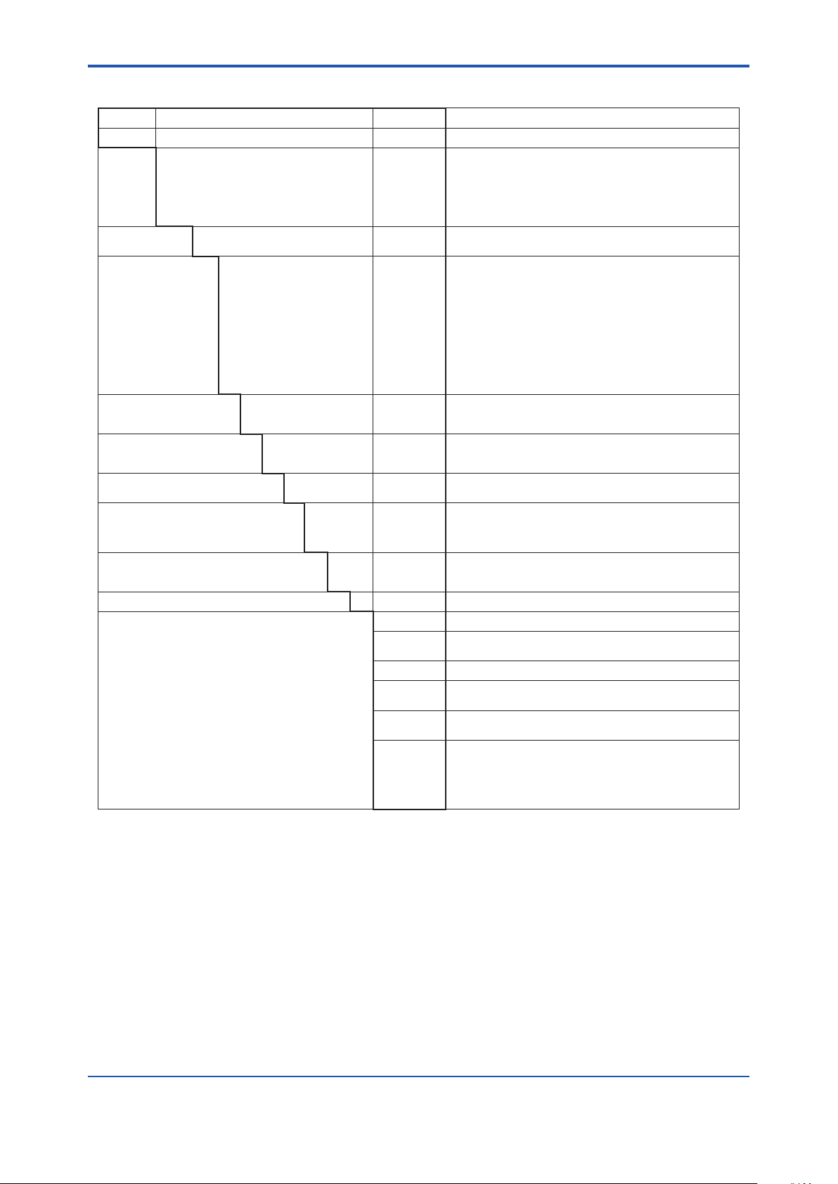
Model and Codes
Model Sufx code Option code Description
ZR202G - - - - - - - - - - - - - - - - - - - - - - - - - - - - - - - - - - - - - - - - - - - - - - - - Integrated type Zirconia Oxygen Analyzer
Length -040
Wetted material -S
Flange
(*2)
Auto Calibration -N
Reference gas -C
Gas Thread -R
Connection box thread -P
Instruction manual -J
-- -A - - - - - - - - - - Always -A
Options
Valves
Tag plates
NAMUR NE43 compliant
-070
-100
-150
-200
-250
-300
-C
-A
-B
-C
-E
-F
-G
-K
-L
-M
-P
-R
-S
-W
-A
-B
-E
-P
-T
-G
-M
-T
-E
-C
*1 For the horizontally installed probe whose insertion length is 2.5 m or more, use the Probe Protector. Be sure to specify
ZO21R-L-200-. Specify the ange sufx code either -C or -K.
*2 The thickness of the ange depends on its dimensions.
*3 Inconel probe bolts and U shape pipe are used. Use this option for high temperature use (ranging from 600 to 700°C).
*4 Specify either /CV or /SV option code.
*5 Specify either /SCT or /PT option code.
*6 No need to specify the option codes, /CV and /SV, since the check valves are provided with the Automatic Calibration Unit.
Automatic calibration cannot be used when natural convection is selected as reference gas.
*7 Sun shield hood is still effective even if scratched. Hood is necessary for outdoor installation out of sun shield roof.
*8 Recommended if sample gas contains corrosive gas like chlorine.
*9 Piping for reference gas must be installed to supply reference gas constantly at a specied ow rate.
*10 Output signal limits: 3.8 to 20.5 mA. Specify either /C2 or /C3 option code.
- - - - - - - - - -
- - - - - - - - - -
- - - - - - - - - -
- - - - - - - - - -
- - - - - - - - - -
- - - - - - - - - -
- - - - - - - - - -
- - - - - - - - - -
- - - - - - - - - -
- - - - - - - - - -
- - - - - - - - - -
- - - - - - - - - -
- - - - - - - - - -
- - - - - - - - - -
- - - - - - - - - -
- - - - - - - - - -
- - - - - - - - - -
- - - - - - - - - -
- - - - - - - - - -
- - - - - - - - - -
- - - - - - - - - -
- - - - - - - - - -
- - - - - - - - - -
- - - - - - - - - -
- - - - - - - - - -
- - - - - - - - - -
- - - - - - - - - -
- - - - - - - - - -
- - - - - - - - - -
- - - - - - - - - -
- - - - - - - - - -
- - - - - - - - - -
- - - - - - - - - -
- - - - - - - - - -
- - - - - - - - - -
- - - - - - - - - -
- - - - - - - - - -
/C Inconel bolt (*3)
/CV
/SV
/H Hood (*7)
/F1
/F2
/SCT
/PT
/C2
/C3
0.4 m
0.7 m
1.0 m
1.5 m
2.0 m
2.5 m (*1)
3.0 m (*1)
SUS316
Stainless steel with Inconel calibration gas tube (*8)
ANSI Class 150 2 RF SUS304
ANSI Class 150 3 RF SUS304
ANSI Class 150 4 RF SUS304
DIN PN10 DN50 A SUS304
DIN PN10 DN80 A SUS304
DIN PN10 DN100 A SUS304
JIS 5K 65 FF SUS304
JIS 10K 65 FF SUS304
JIS 10K 80 FF SUS304
JIS 10K 100 FF SUS304
JPI Class 150 4 RF SUS304
JPI Class 150 3 RF SUS304
Westinghouse
Not required
Horizontal mounting (*6)
Vertical mounting (*6)
Natural convection
External connection (Instrument air) (*9)
Pressure compensated (*9)
Rc 1/4
1/4 NPT (Female)
G1/2
Pg13.5
M20x1.5 mm
1/2NPT
Japanese
English
Chinese
Check valve (*4)
Stop valve (*4)
Dust Filter
Dust Guard Protector
Stainless steel tag plate (*5)
Printed tag plate (*5)
Failure alarm down-scale:
Output status at CPU failure and hardware error is 3.6 mA or less
(*10)
Failure alarm up-scale:
Output status at CPU failure and hardware error is 21.0 mA or more
(*10)
Page 26
<2. Specications>
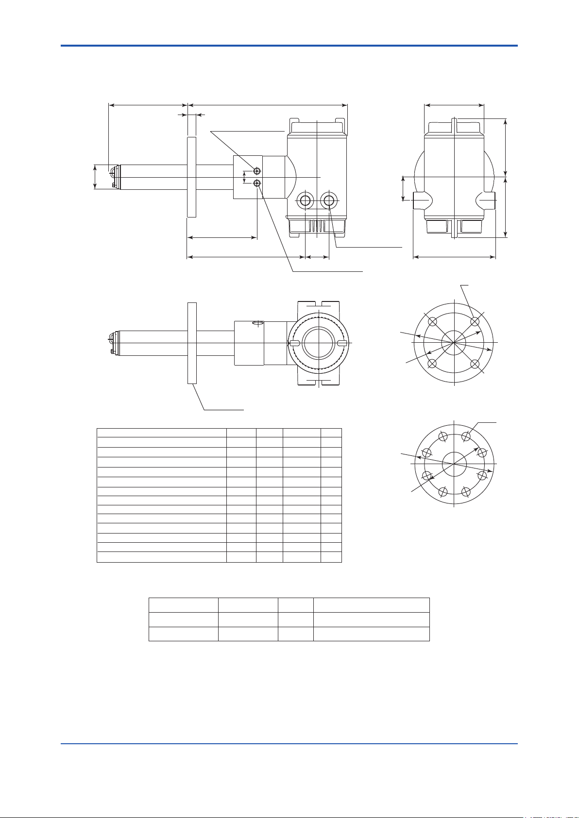
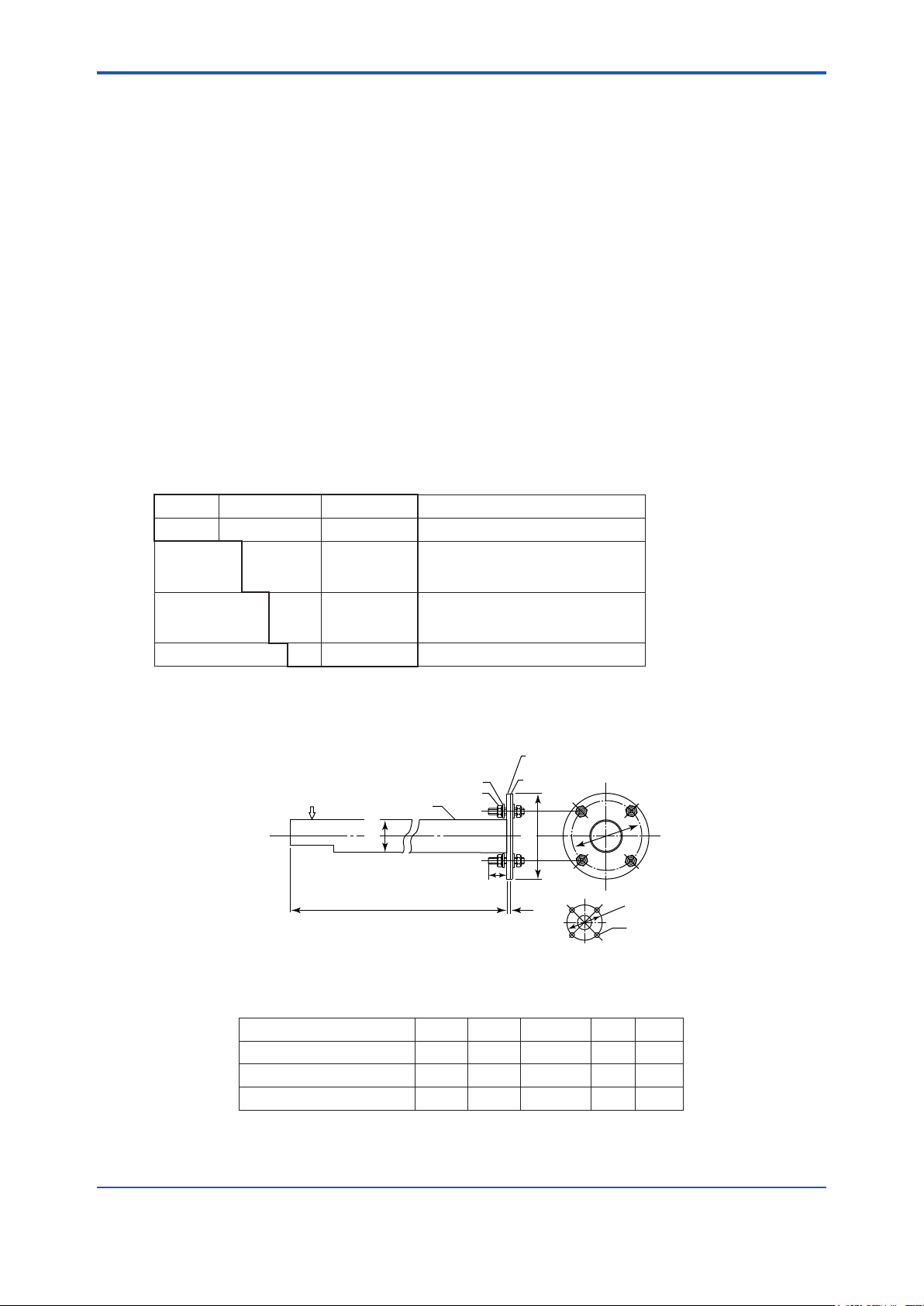
F11_01.ai
25
t
153 to 164
125
L
170
252 to 265
49
48.5
338 to 351
122
L= 0.4, 0.7,
1.0, 1.5, 2.0,
2.5, 3.0 (m)
4-G1/2,2-1/2NPT etc.
Cable connection port
Display side
ANSI Class 150 2 RF SUS304
ANSI Class 150 3 RF SUS304
ANSI Class 150 4 RF SUS304
DIN PN10 DN50 A SUS304
DIN PN10 DN80 A SUS304
DIN PN10 DN100 A SUS304
JIS 5K 65 FF SUS304
JIS 10K 65 FF SUS304
JIS 10K 80 FF SUS304
JIS 10K 100 FF SUS304
JPI Class 150 4 RF SUS304
JPI Class 150 3 RF SUS304
Westinghouse
152.4
190.5
228.6
165
200
220
155
175
185
210
229
190
155
120.6
152.4
190.5
125
160
180
130
140
150
175
190.5
152.4
127
4 - Ø19
4 - Ø19
8 - Ø19
4 - Ø18
8 - Ø18
8 - Ø18
4 - Ø15
4 - Ø19
8 - Ø19
8 - Ø19
8 - Ø19
4 - Ø19
4 - Ø11.5
A B C
19
24
24
18
20
20
14
18
18
18
24
24
14
t
Ø50.8
Rc1/4 or 1/4NPT
Reference gas inlet
Rc1/4 or 1/4NPT
Calibration gas inlet
Ø123
Terminal side
C
Flange
Flange
Ø
B
C
Flange
Ø
A
Flange
Ø
A
Ø
B
• External Dimensions
Model ZR202G Integrated type Zirconia Oxygen Analyzers Unit: mm
2-7
• Standard Accessories
Fuse A1113EF 1 3.15 A
Allen wrench L9827AB 1 For lock screw
Item Parts. No. Q'ty Description
IM 11M12A01-04E
Page 27
<2. Specications>
2-8
IM 11M12A01-04E
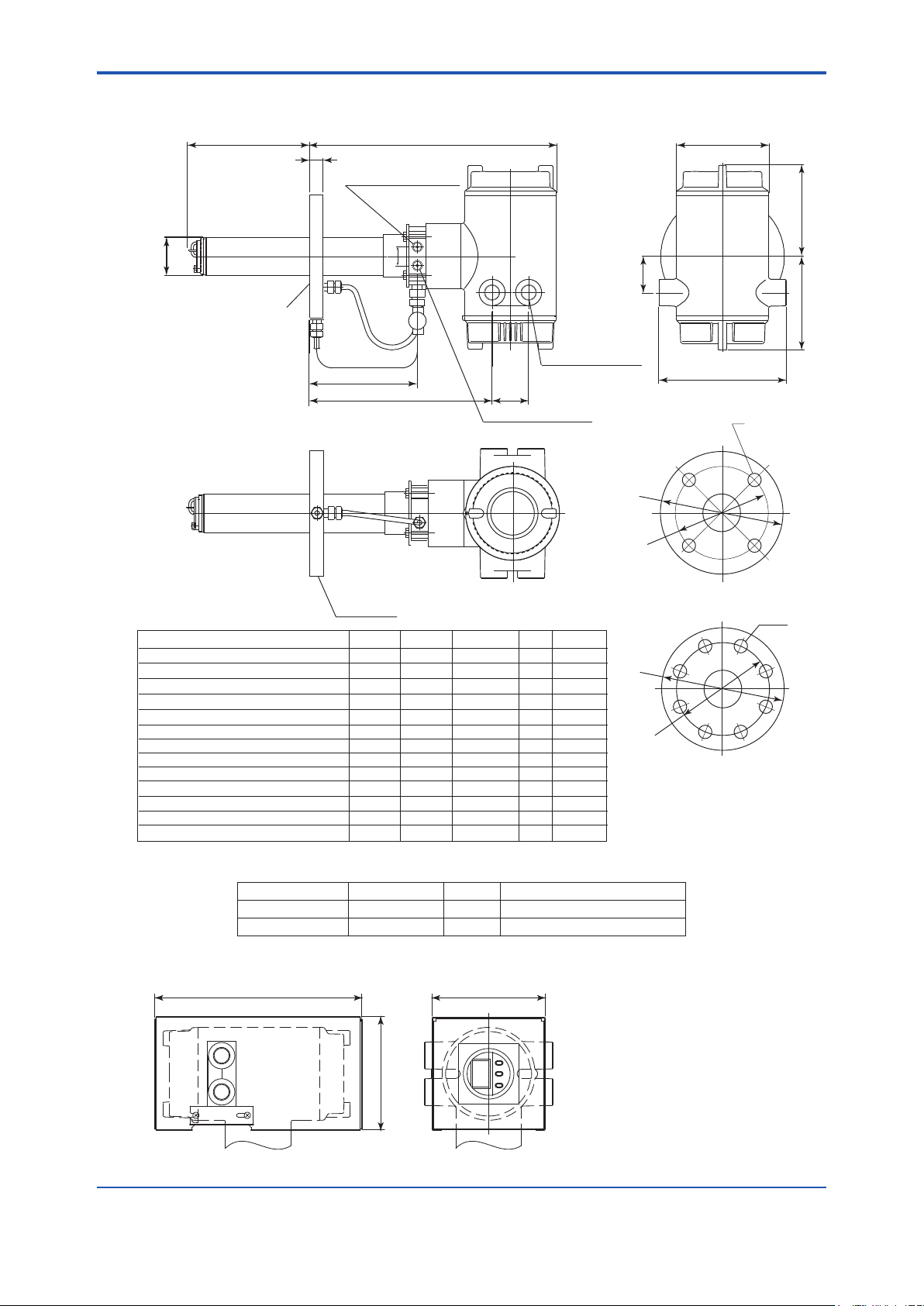
F11_02.EPS
Flange
156 ± 3
125
170
256 ± 4
49
48.5
Ø123
342 ± 4
25
t
122
Terminal side
PIPING:A
PIPING
:B
PIPING
A
B
B
A
B
B
A
A
B
B
B
B
A
ANSI Class 150 2 RF SUS304
ANSI Class 150 3 RF SUS304
ANSI Class 150 4 RF SUS304
DIN PN10 DN50 A SUS304
DIN PN10 DN80 A SUS304
DIN PN10 DN100 A SUS304
JIS 5K 65 FF SUS304
JIS 10K 65 FF SUS304
JIS 10K 80 FF SUS304
JIS 10K 100 FF SUS304
JPI Class 150 4 RF SUS304
JPI Class 150 3 RF SUS304
Westinghouse
152.4
190.5
228.6
165
200
220
155
175
185
210
229
190
155
120.6
152.4
190.5
125
160
180
130
140
150
175
190.5
152.4
127
4 - Ø19
4 - Ø19
8 - Ø19
4 - Ø18
8 - Ø18
8 - Ø18
4 - Ø15
4 - Ø19
8 - Ø19
8 - Ø19
8 - Ø19
4 - Ø19
4 - Ø11.5
A B C
19
24
24
18
20
20
14
18
18
18
24
24
14
t
L
L= 0.4, 0.7,
1.0, 1.5, 2.0,
2.5, 3.0 (m)
4-G1/2,2-1/2NPT etc.
Cable connection port
Ø50.8
Rc1/4 or 1/4NPT
Reference gas inlet
Rc1/4 or 1/4NPT
Calibration gas inlet
Reference gas outlet
Display side
C
Flange
ØB
C
Flange
ØA
Flange
Stop
valve
ØA
ØB
274
150
150
± 4
± 3
± 3
F13.ai
Material of HOOD : Aluminum Food Weight : Approx. 800g
Model ZR202G...-P Integrated type Zirconia Oxygen Analyzer with pressure compensation
Unit: mm
• Standard Accessories
• Hood (Option code /H) Unit: mm
Item Parts. No. Q'ty Description
Fuse A1113EF 1 3.15 A
Allen wrench L9827AB 1 For lock screw
Page 28
<2. Specications>
F2-3E.ai
D
Ø
B
C
Ø
B
Flange <1>
(with bolts, nuts and washer)
gasket (t1.5)
SUS316
Dimensions of
holes on opposing surface
ØA
Gas flow
Washer (12)
Mounting nut (M12)
l (Insert length)
l=1050,1550,2050
Ø60.5
2.1.3 ZO21R Probe Protector
This probe protector is required for the general-use detector when it is used for oxygen concentration
measurements in powdered coal boilers or in uidized furnaces to prevent abrasion due to dust
particles when gas ow exceeds 10 m/sec.
When probe length of the ZR202G is 2.5 m or more and mounted horizontally, be sure to select a
probe protector ZO21R-L-200-*B to support the probe.
Insertion Length: 1.05 m, 1.55 m, 2.05 m.
Flange: JIS 5K 65A FF equivalent, ANSI Class 150 4 FF (without serration)
equivalent or DIN PN10 DN50A equivalent. However, ange thickness is
different.
Material: SUS316 (JIS), SUS304 (JIS) (Flange)
2-9
Weight: 1.05m; Approx. 6/10 kg (JIS/ANSI), 1.55 m; Approx. 9/13 kg
Installation: Bolts, nuts, and washers are provided for detector, probe adapter and
• Model and Codes
Model Sufx code Option code Description
ZO21R -L - - - - - - - - - - - - Probe Protector(0 to 700°C)
Insertion
length
Flange ( *1) -J
Style code *B - - - - - - - - - - - - Style B
*1 Thickness of ange depends on dimensions of ange.
• External Dimension
(JIS/ANSI), 2.05 m; Approx. 12/16 kg (JIS/ANSI)
process-side ange.
-100
-150
-200
-A
-E
- - - - - - - - - - - -
- - - - - - - - - - - -
- - - - - - - - - - - -
- - - - - - - - - - - -
- - - - - - - - - - - -
- - - - - - - - - - - -
1.05 m (3.5 ft)
1.55 m (5.1 ft)
2.05 m (6.8 ft)
JIS 5K 65 FF SUS304
ANSI Class 150 4 FF SUS304
DIN PN10 DN50A SUS304
Unit: mm
Flange<1> A B C t D
JIS 5K 65 FF SUS304 155 130 4 - Ø15 5 40
ANSI Class 150 4 FF SUS304 228.6 190.5 8 - Ø19 12 50
DIN PN10 DN50A SUS304 165 125 4 - Ø18 12 50
IM 11M12A01-04E
Page 29
<2. Specications>
2-10
IM 11M12A01-04E
NOTE
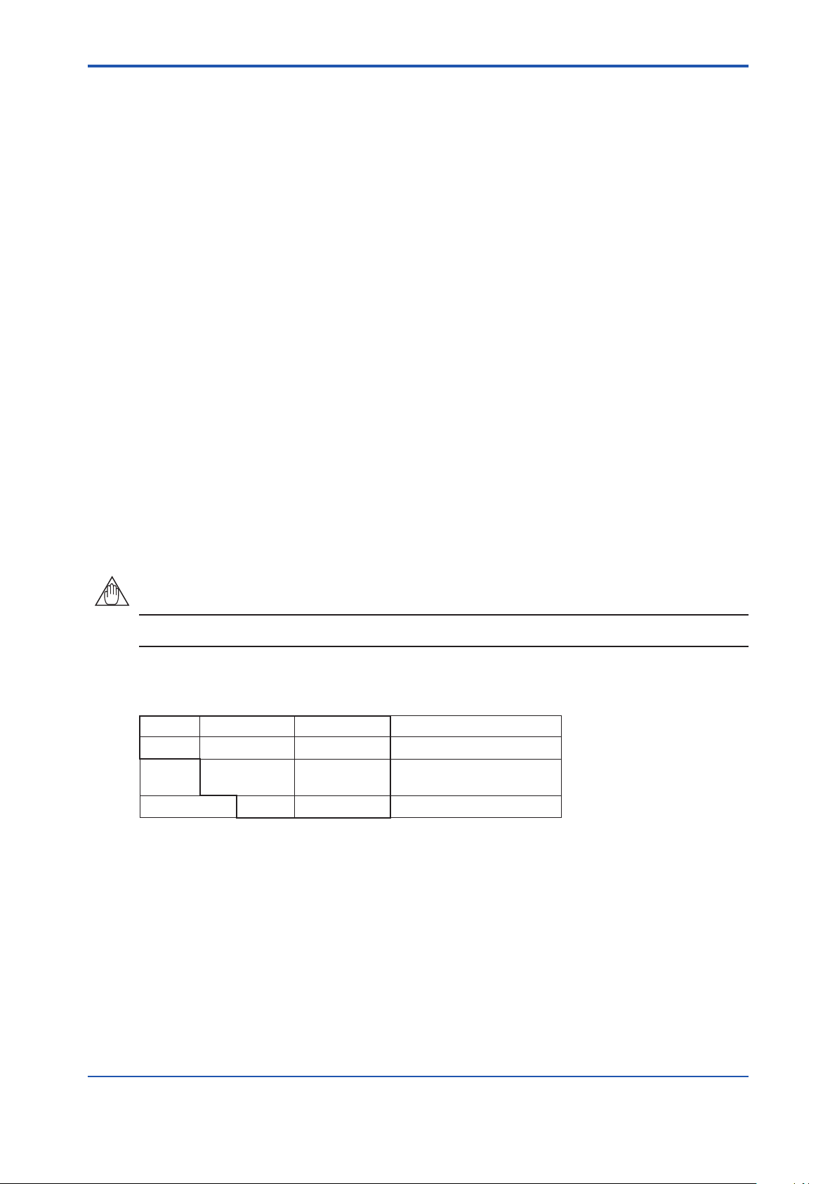
2.2 ZA8F Flow Setting Unit and ZR20H Automatic Calibration Unit
2.2.1 ZA8F Flow Setting Unit
This ow setting unit is applied to the reference gas and the calibration gas in a system conguration
(System 2).
This unit consists of a owmeter and ow control valves to control the ow of calibration gas and
reference gas.
• Standard Specications
Flowmeter: Calibration gas; 0.1 to 1.0 l/min. Reference gas; 0.1 to 1.0 l/min.
Construction: Dust-proof and rainproof construction
Case Material: SPCC (Cold rolled steel sheet)
Painting: Baked epoxy resin, Dark-green (Munsell 2.0 GY 3.1/0.5 or equivalent)
Tube Connections: Rc1/4 or 1/4FNPT
Reference Gas Pressure: Clean air supply of sample gas pressure plus approx. 50 kPa G (or
sample gas pressure plus approx.150 kPa G when a check valve is used,
maximum pressure rating is 300 kPa) (pressure at inlet of the automatic
calibration unit)
Air Consumption: Approx. 1.5 l/min
Weight: Approx. 2 kg
Used instrument air for span calibration gas, if without instrument air is used, contact YOKOGAWA.
• Model and Codes
Model Sufx code Option code Description
ZA8F - - - - - - - - - - - - - - - - - - - - - - - Flow setting unit
Joint
Style code *C - - - - - - - - - - - - Style C
-J
-A
- - - - - - - - - - - -
- - - - - - - - - - - -
Rc 1/4
With 1/4 NPT adapter
Page 30
<2. Specications>
CHECK
OUT
REF
OUT
REFERENCE
SPAN
ZERO
REFERENCE CHECK
AIR
IN
ZERO
IN
SPAN
IN
CHECK
OUT
PIPNG INSIDE THE FLOW SETTING UNIT
Unit : mm (inch)
Weight : Approx. 2.3 kg
Flowmeter Flowmeter
ZERO
GAS IN
AIR IN
Instrument air
Approx. 1.5 l/min.
Air Set
REF
OUT
SPAN
GAS IN
20
2035
35
35
35
35
70
32
7
222.8
235.8
140
180
7
Reference gas outlet
Calibration gas outlet
ø6 Hole
Span gas inlet
Zero gas inlet
2B mounting pipe
Instrument air inlet
F2.6E.ai
Air pressure ;
without check valve ; sample gas pressure + approx.50 kPaG
with check valve ; sample gas pressure + approx.150 kPaG
Piping connection port A
ZA8F-J*C
ZA8F-A*C
5 - Rc1/4
5 - 1/4NPT
Model
Piping connection port A
• External Dimensions
2-11
IM 11M12A01-04E
Page 31

<2. Specications>
2-12
IM 11M12A01-04E
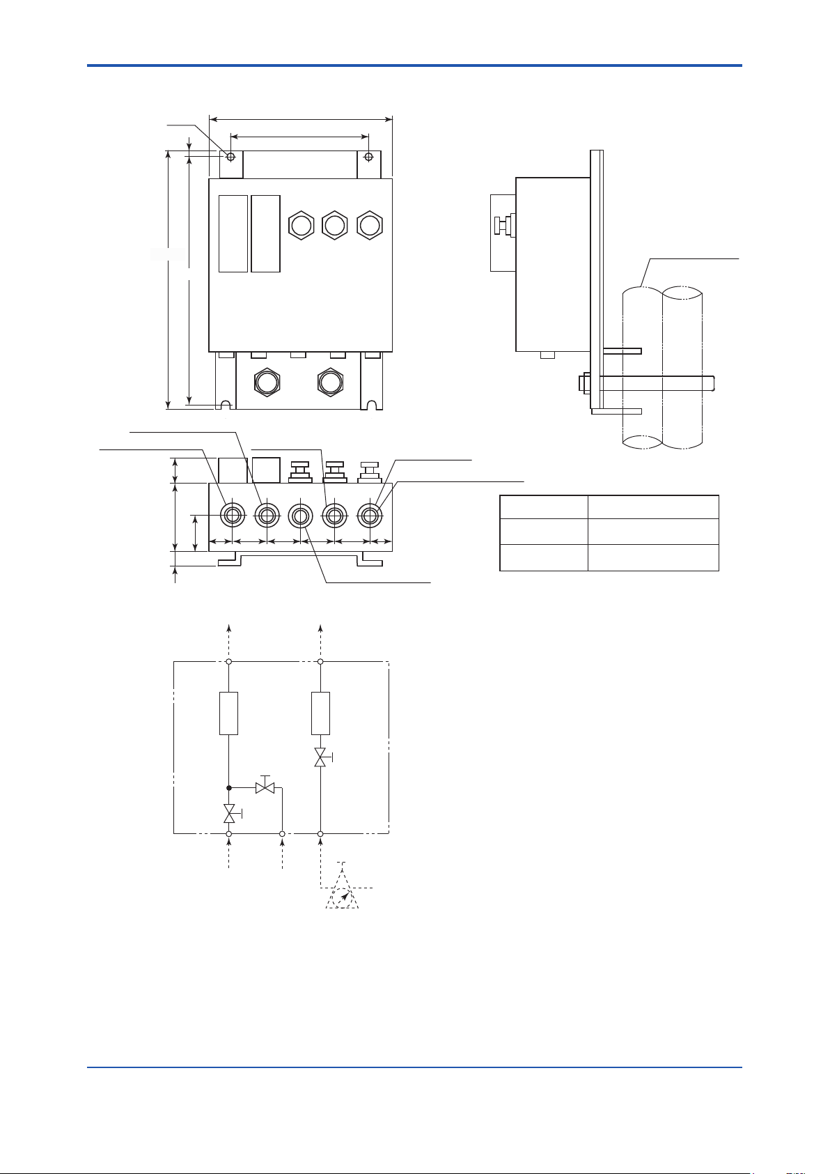
2.2.2 ZR20H Automatic Calibration Unit
This automatic calibration unit is applied to supply specied ow of reference gas and calibration gas
during automatic calibration to the detector in a system conguration (System 3).
• Specications
Equipped with the analyzer when automatic calibration is specied in the sufx code of the ZR202G
Integrated type by selecting either “-A (Horizontal mounting)” or “-B (Vertical mounting)”. The ZR20H
should be arranged when automatic calibration is to be required after the ZR202G has been installed.
Ask Yokogawa service station for its mounting.
Construction: Dust-proof and rainproof construction; NEMA4X/IP67 (excluding owmeter)
Mounting: Mounted on ZR202G, no vibration
Materials: Body; Aluminum alloy, Piping; SUS316 (JIS), SUS304 (JIS), Flowmeter;
Finish: Polyurethane corrosion-resistance coating
Piping Connection: Rc 1/4 or 1/4 NPT
Power Supply: 24V DC (from ZR202G)
Power consumption: Approx.1.3 W
Reference Gas Pressure: Sample gas pressure plus Approx. 150 kPa (690 kPa max.), (Pressure at
Air Consumption: Approx. 1.5 l/min
Weight: Approx. 2 kg
Ambient Temperature: -20 to +55°C, no condensing and freezing
Ambient Humidity: 0 to 95% RH
Storage Temperature: -30 to +65°C
• Model and Codes
Model Sufx code Option code Description
ZR20H - - - - - - - - - - - - - - - - - - - - - - - - - - - - -
Gas piping
connection-R-T
Reference gas *2 -E
Mounting -A
– -A - - - - - - - - - - - -
*1 Ask Yokogawa service station for additional mounting of ZR20H to the preinstalled ZR202G.
*2 Select the appropriate reference gas of ZR20H according to the one of ZR202G.
MA (Methacrylate resin), Bracket; SUS304 (JIS)
Case; Mint green (Munsell 5.6 BG3.3 /2.9)
Cover; Mint green (Munsell 5.6 BG3.3/2.9)
inlet of automatic calibration unit)
Automatic calibration unit for ZR202G *1
- - - - - - - - - - - -
- - - - - - - - - - - -
-P
-B
- - - - - - - - - - - -
- - - - - - - - - - - -
- - - - - - - - - - - -
- - - - - - - - - - - -
Rc 1/4
1/4 NPT
Instrument air
Pressure compensated
Horizontal mounting
Vertical mounting
Always -A
Page 32
<2. Specications>
Rc1/4 or 1/4NPT(Female)
Rc1/4 or 1/4NPT(Female)
Rc1/4 or 1/4NPT(Female)
Rc1/4 or 1/4NPT(Female)
Rc1/4 or 1/4NPT(Female)
Rc1/4 or 1/4NPT(Female)
SPAN IN REF IN ZERO IN
AUTO CAL. UNIT
-20 TO 558C
ZR20HMODEL
SUFFIX
STYLE
AMB.TEMP
NO.
S1
SUPPLY 690kPa MAX.
USED WITHZR202G
ZR202GUSED WITH
690kPa MAX.SUPPLY
S1
NO.
AMB.TEMP
STYLE
SUFFIX
MODEL ZR20H
-20 TO 558C
AUTO CAL. UNIT
SPAN IN REF IN ZERO IN
[ 84
166.5
Ø80
243
258
166.5
5644
180MAX444040 66.5
49111
66.540 40
Ø84
Span gas inlet
Zero gas inlet
Reference gas inlet
Zero gas inlet
Reference gas inlet
Span gas inlet
MAX
(2) Vertical Mounting (-B)
Unit: mm
Ø80
44
SPAN IN
REF. IN
ZERO IN
F4.11E.ai
Calibration gas
Reference gas
ZR202G body
Span gas
solenoid valve
Span gas flowmeter
Reference gas flowmeter
To Air set
To Zero gas cylinder
Needle valve
Automatic calibration unit
Zero gas flowmeter
Zero gas
solenoid valve
Check valve
External Dimensions
(1) Horizontal Mounting (-A)
2-13
PIPNG INSIDE THE AUTOMATIC CALIBRATION UNIT
IM 11M12A01-04E
Page 33
<2. Specications>
2-14
IM 11M12A01-04E
92
228
253
1600
354
Flow checker
Span gas valve
Zero gas valve
Gas outlet
F24.ai
Zero gas cylinder (6 cylinder): E7050BA
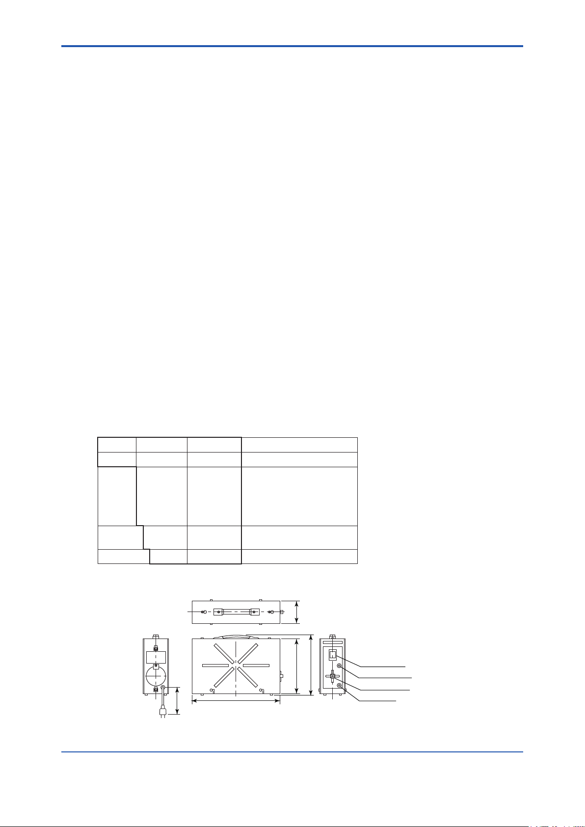
2.3 ZO21S Standard Gas Unit
This is a handy unit to supply zero gas and span gas to the detector in a system conguration based
on System 1. It is used in combination with the detector only during calibration.
• Standard Specications
Function: Portable unit for calibration gas supply consisting of span gas (air) pump, zero
gas cylinder with sealed inlet, ow rate checker and ow rate needle valve.
Sealed Zero Gas Cylinders (6 provide): E7050BA
Capacity: 1 l
Filled pressure: Approx. 686 kPa G (at 35 °C)
Composition: 0.95 to 1.0 vol% O
Power Supply: 100, 110, 115, 200, 220, 240V AC± 10%, 50/60 Hz
Power Consumption: Max. 5 VA
Case material: SPCC (Cold rolled steel sheet)
Paint: Epoxy resin, baked
Paint Color: Mainframe; Munsell 2.0 GY3.1/0.5 equivalent
Piping: Ø6 x Ø4mm exible tube connection
Weight: Approx. 3 kg
Span gas: Internal pump draws in air from atmosphere, and feeds to detector.
* Non CE Mark.
• Model and Codes
Model Sufx code Option code Description
ZO21S - - - - - - - - - - - - - - - - - - - - - Standard gas unit
-2
Power
supply
Panel
Style code *A - - - - - - - - - - - Style A
-3
-4
-5
-7
-8
balance
2+N2
Cover; Munsell 2.8 GY6.4/0.9 equivalent
- - - - - - - - - - -
- - - - - - - - - - -
- - - - - - - - - - -
- - - - - - - - - - -
- - - - - - - - - - -
- - - - - - - - - - -
-J
-E
- - - - - - - - - - -
- - - - - - - - - - -
200 V AC 50/60 Hz
220 V AC 50/60 Hz
240 V AC 50/60 Hz
100 V AC 50/60 Hz
110 V AC 50/60 Hz
115 V AC 50/60 Hz
Japanese version
English version
• External Dimensions
Page 34
<2. Specications>
Ø51
32
10
Carborundum filter (SiC)
Increasing of insertion length
F31.EPS
Screw
Detector
Attach the filter
unit to the tip of
the detector
by screwing
it clockwise.
4-Ø6
122
Ø50.8
100
Increasing of insertion length
F11-1.ai
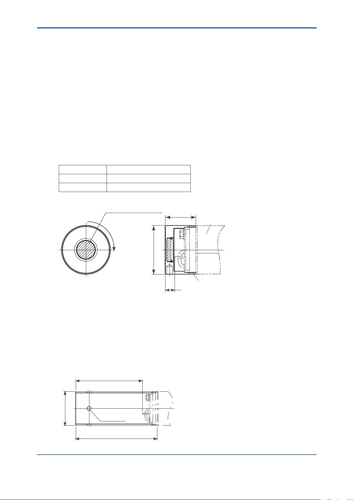
2.4 Other Equipment
2.4.1 Dust Filter for Oxygen Analyzer (part no. K9471UA)
This lter is used to protect the detector sensor from corrosive dust components or from a high
concentration of dust when the oxygen concentration in utility boilers or concrete kilns are to be
measured.
This lter requires the measuring gas ow of 1 m/sec or faster to replace gas inside zirconia sensor.
• Standard specications
Applicable detector: Standard-type detector for general-use (the sample gas ow should be
approximately perpendicular to the probe.)
Mesh: 30 microns
Material: Carborundum (Filter), SUS316 (JIS)
Weight: Approx. 0.2 kg
Part No. Description
K9471UA Filter
K9471UX Tool
2-15
Unit: mm
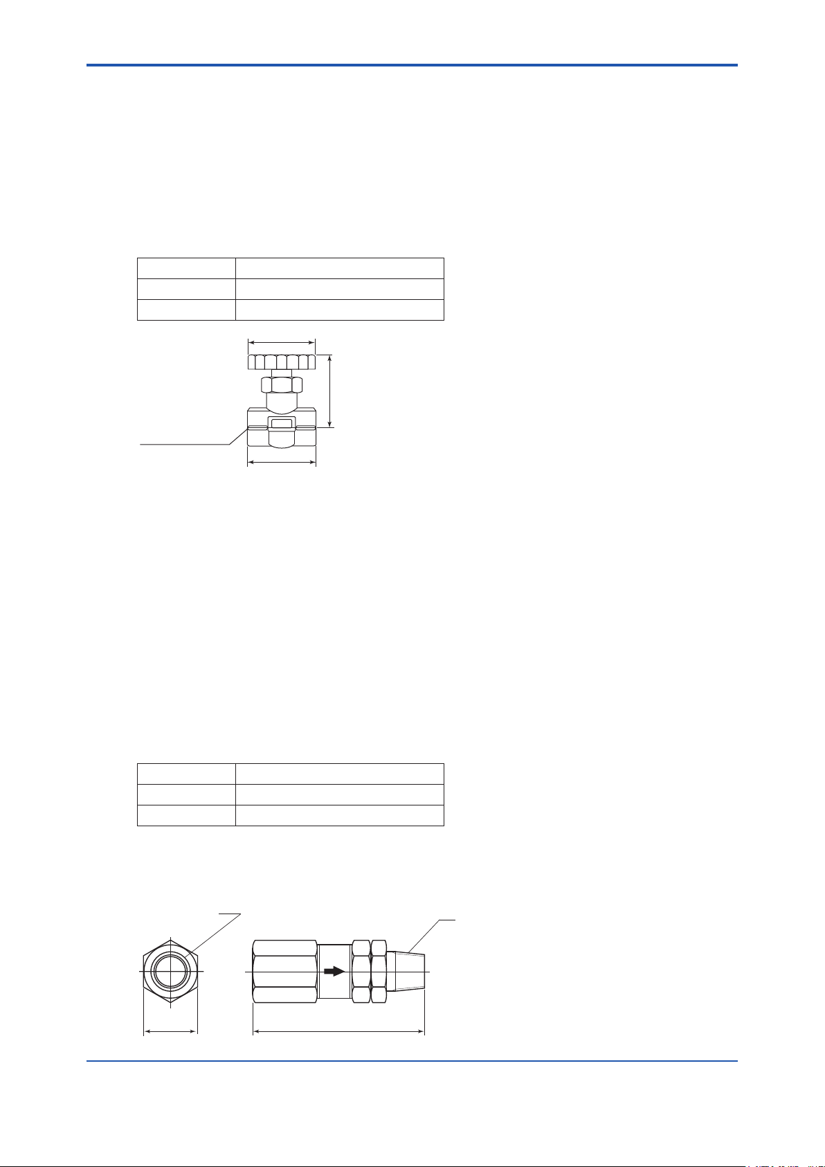
2.4.2 Dust Guard Protector (part no. K9471UC)
Recommended to be used when sample gas is likely to ow directly into the cell due to its ow
direction in the stack or the like, ammable dust may go into the cell, or water drops are likely to fall
and remain in the cell during downtime or the like due to the installation position.
Material: SUS316 Unit: mm
Weight: Approx. 0.3 kg
IM 11M12A01-04E
Page 35
<2. Specications>
2-16
IM 11M12A01-04E
F15.ai
55
(Full open length)
40
Rc1/4 or 1/4NPT
Ø43
K9292DN : Rc 1/4(A),R 1/4(B)
K9292DS : 1/4FNPT(A),1/4NPT(Male)(B)
F30.EPS
Approx. 19 Approx. 54
Unit: mm
A
B
2.4.3 Stop Valve (part no. L9852CB or G7016XH)
This valve is mounted on the calibration gas line in the system to allow for one-touch calibration. This
is applied to a system conguration (System 1).
• Standard Specication
Connection: Rc 1/4 or 1/4 FNPT
Material: SUS 316 (JIS)
Weight: Approx. 80 g
Part No. Description
L9852CB Joint: Rc 1/4, Material: SUS316 (JIS)
G7016XH Joint: 1/4 NPT, Material: SUS316 (JIS)
2.4.4 Check Valve (part no. K9292DN or K9292DS)
This valve is mounted on the calibration gas line (directly connected to the detector). This is applied to
a system based on the system conguration (System 2 and 3).
This valve prevents the sample gas from entering the calibration gas line. Although it functions as the
stop valve, operation is easier as it does not require opening/closing at each calibration.
Screw the check valve into the calibration gas inlet of the detector instead of the stop valve.
• Standard Specications
Connection: Rc1/4 or 1/4FNPT
Material: SUS304 (JIS)
Pressure: Between 150 kPa G or more 350 kPa G or less
Weight: Approx. 40 g
Part No. Description
K9292DN Joint: Rc 1/4, Material: SUS304 (JIS)
K9292DS Joint: 1/4 NPT, Material: SUS304 (JIS)
Page 36

<2. Specications>
Ø74
Primary
Secondary
88
Max. 210
max. 55
Approx. 122
Secondary
pressure
gauge
Panel (Horizontal mounting)
Panel (Vertical mounting)
G7003XF, G7004XF: Rc 1/4
K9473XK, K9473XG: 1/4NPT connector
A
22
ø15
2-ø2.2
+0.5
-0
2-ø6.5
40
2-M6 screw depth 8
40
Horizontal
mounting
Vertical
mounting
Panel cut dimensions
View A
F22_1.ai
Unit : mm
2.4.5 Air Set
This set is used to lower the pressure when instrument air is used as the reference and span gases.
Standard Specications
• Part no. G7003XF or K9473XK
Primary Pressure: Max. 1 MPa G
Secondary Pressure: 0.02 to 0.2 MPa G
Connection: Rc1/4 or 1/4FNPT with joint adapter
Weight: Approx.1 kg
Part No. Description
G7003XF Joint: RC 1/4, Material: Zinc alloy
K9473XK Joint: 1/4 FNPT, Material: Zinc alloy with adapter (SUS316)
• Part. no. G7004XF or K9473XG
Primary Pressure: Max. 1 MPa G
Secondary Pressure: 0.02 to 0.5 MPa G
2-17
Connection: Rc1/4 or 1/4 FNPT with joint adapter
Weight : Approx. 1kg
Part No. Description
G7004XF Joint: RC 1/4, Material: Zinc alloy
K9473XG Joint: 1/4 FNPT, Material: Zinc alloy with adapter (SUS316)
IM 11M12A01-04E
Page 37

<2. Specications>
2-18
IM 11M12A01-04E
Unit : mm
Weight : Approx. 6 kg
F32.ai
485
325
ø140
H
I
H
A
C
A
K
T
O
Regulator handle
W22 (Righthanded screw)
Stop valve
Approx.112
IN
Unit : mm
* Outlet
Part No.
G7013XF
G7014XF
* Outlet
Rc1/4
1/4 NPT female screw
Secondary
pressure gauge
Primary
pressure gauge
Secondary
safety valve
Primary
safety valve
Approx. 82
Approx. 59
Approx. 163 Approx. 174
2.4.6 Zero Gas Cylinder (part no. G7001ZC)
The gas from this cylinder is used as the calibration zero gas and detector purge gas.
• Standard Specications
Capacity: 3.4 l
Filled pressure: 9.8 to 12 MPa G
Composition: 0.95 to 1.0 vol%
O2 remaining N
2
(Note) Export of such high pressure lled gas cylinder to most countries is prohibited or restricted.
2.4.7 Pressure Regulator (G7013XF or G7014XF) for Gas Cylinder
This regulator valve is used with the zero gas cylinders.
• Standard Specications
Primary Pressure: Max. 14.8 MPa G
Secondary Pressure: 0 to 0.4 MPa G
Connection: Inlet W22 14 threads, right hand screw
Outlet Rc1/4 or 1/4FNPT
Material: Brass body
Page 38
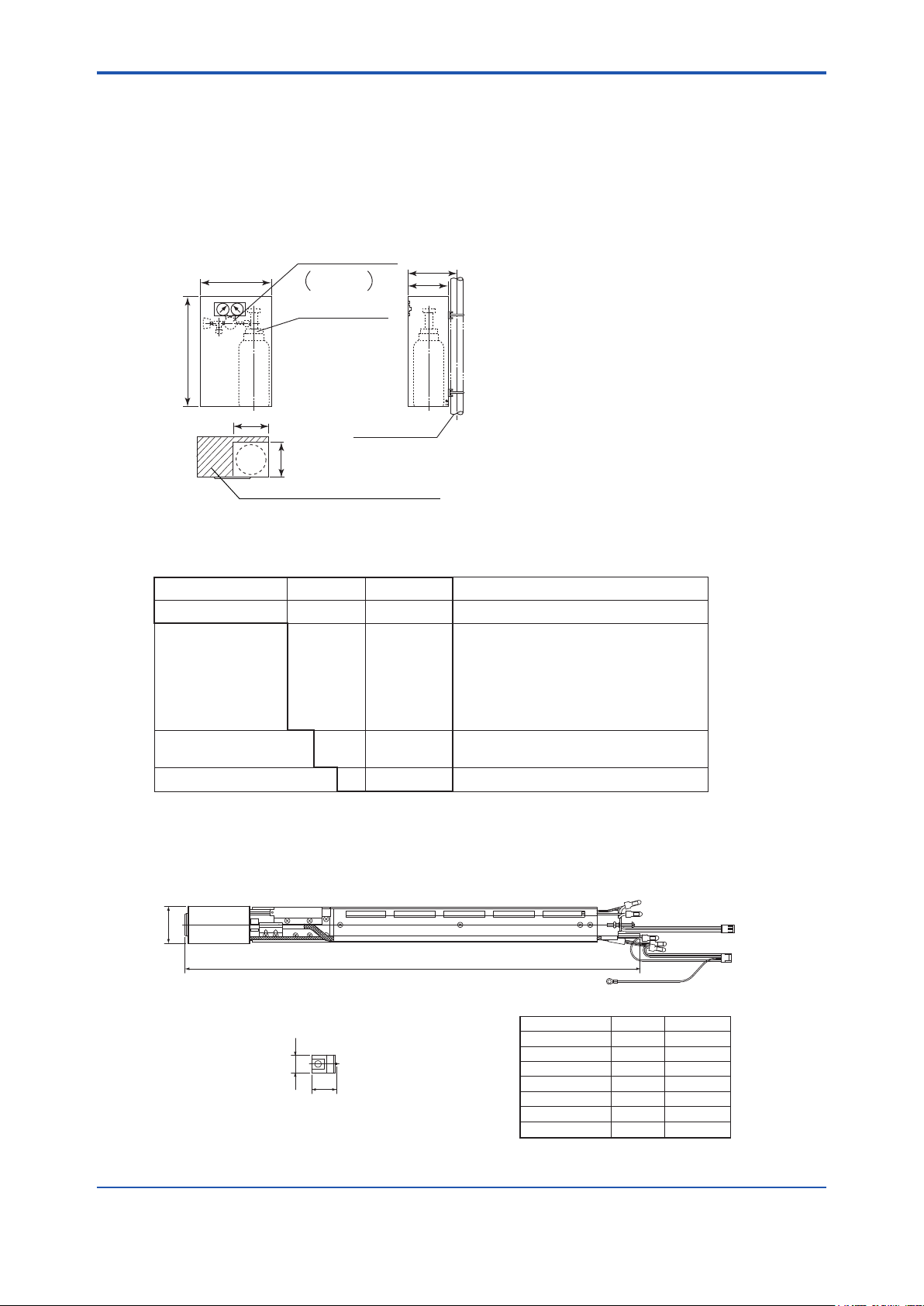
<2. Specications>
324
496
200
180
Pressure regulator
Zero gas cylinder
2B mounting pipe
( Ø60.5 )
(G7001ZC)
G7013XF/
G7014XF
F23.ai
(Note)The zero gas cylinder and the regulator valve are not included in the E7044KF (case assembly)
(158.3)
(160)
The oblique line is an opening portion.
K9470BX
ZR202A-040
ZR202A-070
ZR202A-100
ZR202A-150
ZR202A-200
ZR202A-250
ZR202A-300
552
852
1152
1652
2152
2652
3152
Approx. 0.8
Approx. 1.2
Approx. 1.6
Approx. 2.2
Approx. 2.8
Approx. 3.4
Approx. 4.0
Jig for change
L±12
(K9470BX)
Ø 21.7
30
Unit : mm
Ø 45
L: length
L
Weight (kg)
Model & Code
F2.16.EPS
2.4.8 Case Assembly (E7044KF) for Calibration gas Cylinder
This case is used to store the zero gas cylinders.
• Standard Specications
Case Paint: Baked epoxy resin, Jade green (Munsell 7.5 BG 4/1.5)
Installation: 2B pipe mounting
Weight: Approx. 10 kg (including gas cylinder)
(Note) Export of such high pressure lled gas cylinder to most countries is prohibited or restricted.
2-19
2.4.9 ZR202A Heater Assembly
Model Sufx code Option code Description
ZR202A - - - - - - - - - - - - - - - - - - - - Heater Assembly for ZR202G
Length (*1) -040
-070
-100
-150
-200
-250
-300
Jig for change -A
-N
-- -A - - - - - - - - - - - Always -A
*1 Sufx code of length should be selected as same as ZR202G installed.
*2 Jig part no. is K9470BX to order as a parts after purchase.
(Note) The heater is made of ceramic, do not drop or subject it to pressure stress.
External Dimensions
- - - - - - - - - - -
- - - - - - - - - - -
- - - - - - - - - - -
- - - - - - - - - - -
- - - - - - - - - - -
- - - - - - - - - - -
- - - - - - - - - - -
- - - - - - - - - - -
- - - - - - - - - - -
0.4 m
0.7 m
1 m
1.5 m
2 m
2.5 m
3 m
with Jig (*2)
None
IM 11M12A01-04E
Page 39

Blank Page
Page 40
<3. Installation>
NOTE
CAUTION
3. Installation
This chapter describes installation of the following equipment:
3.1 Model ZR202G Integrated type Zirconia Oxygen Analyzer
3.2 Model ZA8F Flow Setting Unit
3.3 Model ZR20H Automatic Calibration Unit
3.4 Case Assembly (E7044KF) for Calibration gas Cylinder
3.1 Installation of ZR202G Zirconia Oxygen Analyzer
3.1.1 Installation Location
The following should be taken into consideration when installing the probe:
(1) Easy and safe access to the probe for checking and maintenance work.
(2) Ambient temperature of not more than 55°C, and the terminal box should not be affected by
radiant heat.
3-1
(3) A clean environment without any corrosive gases.
A natural convection type analyzer (model ZR202G-----C), which uses ambient air as
reference gas, requires that the ambient oxygen concentration be constant. Automatic calibration
cannot be used when natural convection is selected as reference gas.
(4) No vibration.
(5) The sample gas satises the specications described in Chapter 2.
(6) No sample gas pressure uctuations.
• The ambient temperature of the ZR202G Integrated type Zirconia Oxygen Analyzer should be
between - 20°C and 55°C.
IM 11M12A01-04E
Page 41
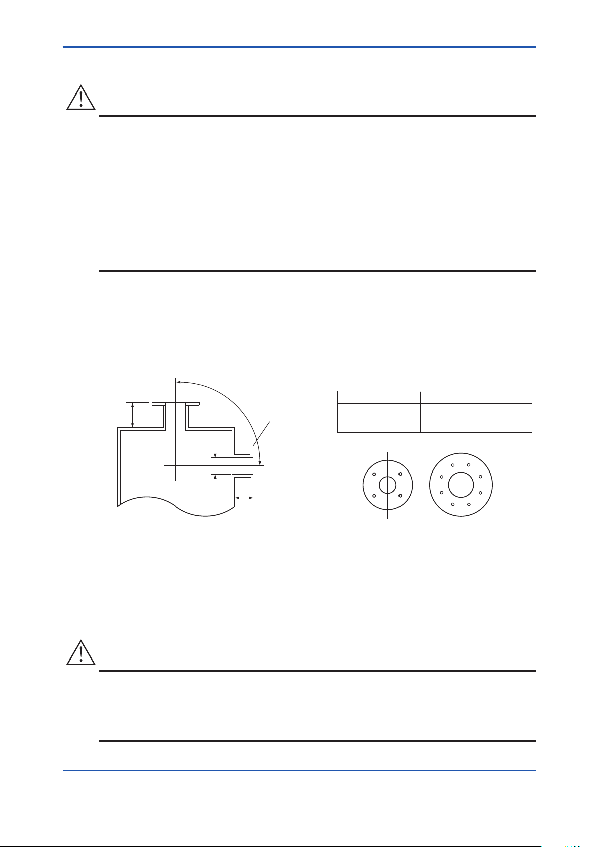
<3. Installation>
3-2
IM 11M12A01-04E
CAUTION
100mm
(vertical)
Bounds of the probe
insertion hole location
Flange matches
the detector size
(horizontal)
100mm
Four-hole flange
Eight-hole flange
F3101E.ai
*1
Note
*1
Type Outside diameter of detector
With dust filter 51 mm in diameter (Note)
With probe protector 60.5 mm in diameter (Note)
Standard 50.8 mm in diameter (Note)
CAUTION
3.1.2 Probe Insertion Hole
• The outside dimension of detector may vary depending on its options. Use a pipe that is large
enough for the detector. Refer to Figure 3.1 for the dimensions.
If the detector is mounted horizontally, the calibration gas inlet and reference gas inlet should
face downwards.
• When using the detector with pressure compensation, ensure that the ange gasket does not
block the reference gas outlet on the detector ange. If the ange gasket blocks the outlet, the
detector cannot conduct pressure compensation. Where necessary, make a notch on the ange
gasket.
• The sensor (zirconia cell) at the probe tip may deteriorate due to thermal shock if water drops are
allowed to fall on it, as it is always at high temperature.
(1) Do not mount the probe with the tip higher than the probe base.
(2) If the probe length is 2.5 m or more, the detector should be mounted vertically (no more than a 5°
tilt).
(3) The detector probe should be mounted at right angles to the sample gas ow or the probe tip
should point downstream.
(Note) When using the detector with pressure compensation, ensure that the flange gasket does not block the reference gas
outlet on the detector flange. If the flange gasket blocks the outlet, the detector cannot perform pressure compensation.
Where necessary, make a notch in the ange gasket.
Figure 3.1 Illustrates an example of the probe insertion hole
3.1.3 Installation of the Probe
• The cell (sensor) at the tip of the detector is made of ceramic (zirconia). Do not drop the detector,
as impact will damage it.
• A gasket should be used between the anges to prevent gas leakage. The gasket material
should be heatproof and corrosion-proof, suited to the characteristics of the sample gas.
Page 42

<3. Installation>
CAUTION
Ø51
32
10
Carborundum filter (SiC)
Increasing of insertion length
F31.EPS
Screw
Detector
Attach the filter unit to the tip of the
detector by screwing it clockwise.
The following should be taken into consideration when mounting the general-use detector:
<General-use detector>
(1) Make sure that the cell mounting screws (four bolts) at the probe tip are not loose.
If a dust lter (see Section 2.4.1) is used, make sure it is properly attached to the detector. Refer
to Section 3.1.4 for installation of the dust lter.
(2) Where the detector is mounted horizontally, the calibration gas inlet and the reference gas inlet
should face downward.
3.1.4 Installation of the Dust Filter (K9471UA), Dust Guard Protector (K9471UC) Probe Protector (ZO21R)
• The dust lter is used to protect the Zirconia sensor from corrosive dust or a high concentration
of dust such as in utility boilers and concrete kilns. If a lter is used in combustion systems other
than these, it may have adverse effects such as response delay. The combustion conditions
should be examined carefully before using a lter.
3-3
• The dust lter requires gas ow of 1 m/sec or faster at the front surface of the lter.
When you specify option code /F1, the detector is shipped with the dust lter mounted.
Follow this procedure when replacing the lter in the detector. It is recommended that you read
Chapter 11 prior to lter mounting, for it is necessary to be familiar with the detector’s construction,
especially the sensor assembly.
(1) Mount the dust lter by putting it on the end of the detector and screw the dust lter clockwise.
Put a hook pin wrench (K9471UX), Ø52 to 55 in diameter, into the hole on the dust lter to fasten
or remove it.
Apply a heat-resistant coating (see Note 1) to the threads on the detector.
Where mounting dust lter after having once removed it from the detector, reapply the heat-
resistant coating.
Note 1:As the detector is heated to 700°C, it is recommended to use the heat-resistant coating on the threads to prevent seizing up.
Name of heat-resistant coating material: “Never-Seez Nickel Special”.
Figure 3.2.1 Installation of the dust lter
IM 11M12A01-04E
Page 43

<3. Installation>
3-4
IM 11M12A01-04E
4-Ø6
122
Ø50.8
100
Increasing of insertion length
F11-1.ai
2050
Ø60.5
Notch
Unit: mm
F3103E.ai
Gasket (t1.5)
Calibration gas inlet
Reference gas inlet
Direction of the sample gas flow
Detector top
< Procedures for installing the dust guard protector (K9471UC)>
The ZR202G is shipped with the dust guard protector when the option code /F2 is specied in case
of ordering the detector. The protector should be used when preventing dusts and water drops from
lowering the detector performance is desired. Screw the protector on the top of the detector so as to
cover the top. When attaching or detaching the protector, perform by hooking holes of its side with
a hook pin wrench for Ø52-55 hole( Pin diameter 4.5 mm: P/N K9471UX or the like) or by pass a
screwdriver through the holes. When re-attaching the protector after detaching it, apply the “NeverSeez Nickel Special” to it.
Figure 3.2.2 Installation of the dust guard protector
<Detector with a probe protector (Model ZO21R-L-200- *B for enhance forth>
The detector is used with a probe protector to support the probe (ZR202G) when the probe length is
2.5m or more and mounted horizontally.
(1) Put a gasket (provided by the user) between the anges and mount the probe protector in the
probe insertion hole.
(2) Make sure that the sensor assembly mounting screws (four bolts) at the probe tip are not loose.
(3) Mount the detector so that the calibration/reference gas inlet faces downward.
Figure 3.3 Probe protector (supporting the mounting strength)
Page 44

<3. Installation>
Direction of the sample gas flow
Mount the protector so that the notch
is on the downstream side of gas flow.
F3104E.ai
1050,1550, 2050
Gasket (t1.5)
Unit: mm
Detector top
Calibration gas inlet
Reference gas inlet
NOTE
<Detector with a probe protector (Model ZO21R-L-- *B for dust wear protect>
The detector is used with a probe protector to prevent the sensor from being worn by dust particles
when there is a high concentration of dust and gas ow exceeds 10 m/sec (ne-carbon boiler or uid-
bed furnace).
(1) Put the gasket that is provided by user between the anges, and mount the probe protector in
the probe insertion hole. The probe protector should be installed so that the notch comes to the
downstream of the sample gas ow.
(2) Make sure that the sensor assembly mounting screws (four bolts) at the probe tip are not loose.
(3) Where the detector is mounted horizontally, the calibration/reference gas inlet should face
downward.
3-5
Figure 3.4 Mounting of detector with a probe protector (Dust wear protect)
When the probe protector is used in the ZR202G with pressure compensation (-P), instrument air
leaking from the probe protector may affect the measured value.
3.2 Installation of ZA8F Flow Setting Unit
3.2.1 Installation Location
The following should be taken into consideration:
(1) Easy access to the unit for checking and maintenance work.
(2) Near to the detector and the converter
(3) No corrosive gas.
(4) An ambient temperature of not more than 55°C and little changes of temperature.
(5) No vibration.
(6) Little exposure to rays of the sun or rain.
IM 11M12A01-04E
Page 45

<3. Installation>
3-6
IM 11M12A01-04E
F3401E.ai
223
140
F3.13E.ai
4 - Ø6 hole, or M5 screw
Unit: mm
3.2.2 Mounting of ZA8F Flow Setting Unit
The ow setting unit can be mounted either on a pipe (nominal JIS 50 A) or on a wall. It should be
positioned vertically so that the owmeter works correctly.
<Pipe Mounting>
(1) Prepare a vertical pipe of sufcient strength (nominal JIS 50A: O.D. 60.5 mm) for mounting the
ow setting unit. (The unit weighs approximately 2 to 3.5 kg.)
(2) Mount the ow setting unit on the pipe by tightening the nuts with the U-bolt so that the metal
tting is rmly attached to the pipe.
Figure 3.12 Pipe Mounting
<Wall Mounting>
(1) Make a hole in the wall as illustrated in Figure 3.13.
Figure 3.13 Mounting holes
Page 46

<3. Installation>
F3.14E.ai
(2) Mount the ow setting unit. Remove the pipe mounting parts from the mount ttings of the ow
setting unit and attach the unit securely on the wall with four screws.
Figure 3.14 Wall mounting
3.3 Installation of ZR20H Automatic Calibration Unit
3-7
3.3.1 Installation Location
The following should be taken into consideration:
(1) Easy access to the unit for checking and maintenance work.
(2) Near to the detector and the converter
(3) No corrosive gas.
(4) An ambient temperature of not more than 55°C and little change of temperature.
(5) No vibration.
(6) Little exposure to rays of the sun or rain.
3.3.2 Mounting of ZR20H Automatic Calibration Unit
ZR202G - - - - - A or B is shipped with automatic calibration unit attached.
The automatic calibration unit includes owmeters and solenoid valves, so as to ensure reliable and
accurate operation – Flowmeter should be mounted vertically. The associated probe is designed for
horizontal or vertical mounting.
If you buy the automatic calibration unit afterward, and need to install it or replace it, contact our
service representative.
IM 11M12A01-04E
Page 47

<3. Installation>
3-8
IM 11M12A01-04E
Zero gas inlet
Rc1/4 or 1/4NPT(Female)
Reference gas inlet
Rc1/4 or 1/4NPT(Female)
Terminal box side
Span gas inlet
Rc1/4 or 1/4NPT(Female)
166.5
258
243
214 MAX44 66.540 40
Vertical mounting on the ZR202G (-B)
F3.15E.ai
Horizontal mounting on the ZR202G (-A)
Unit: mm
Display side
Zero gas inlet
Rc1/4 or 1/4NPT(Female)
Span gas inlet
Rc1/4 or 1/4NPT(Female)
Reference gas inlet
Rc1/4 or 1/4NPT(Female)
166.5
60
45 160
66.540 40180 MAX44
Figure 3.15 Automatic Calibration Unit Mounting
Page 48
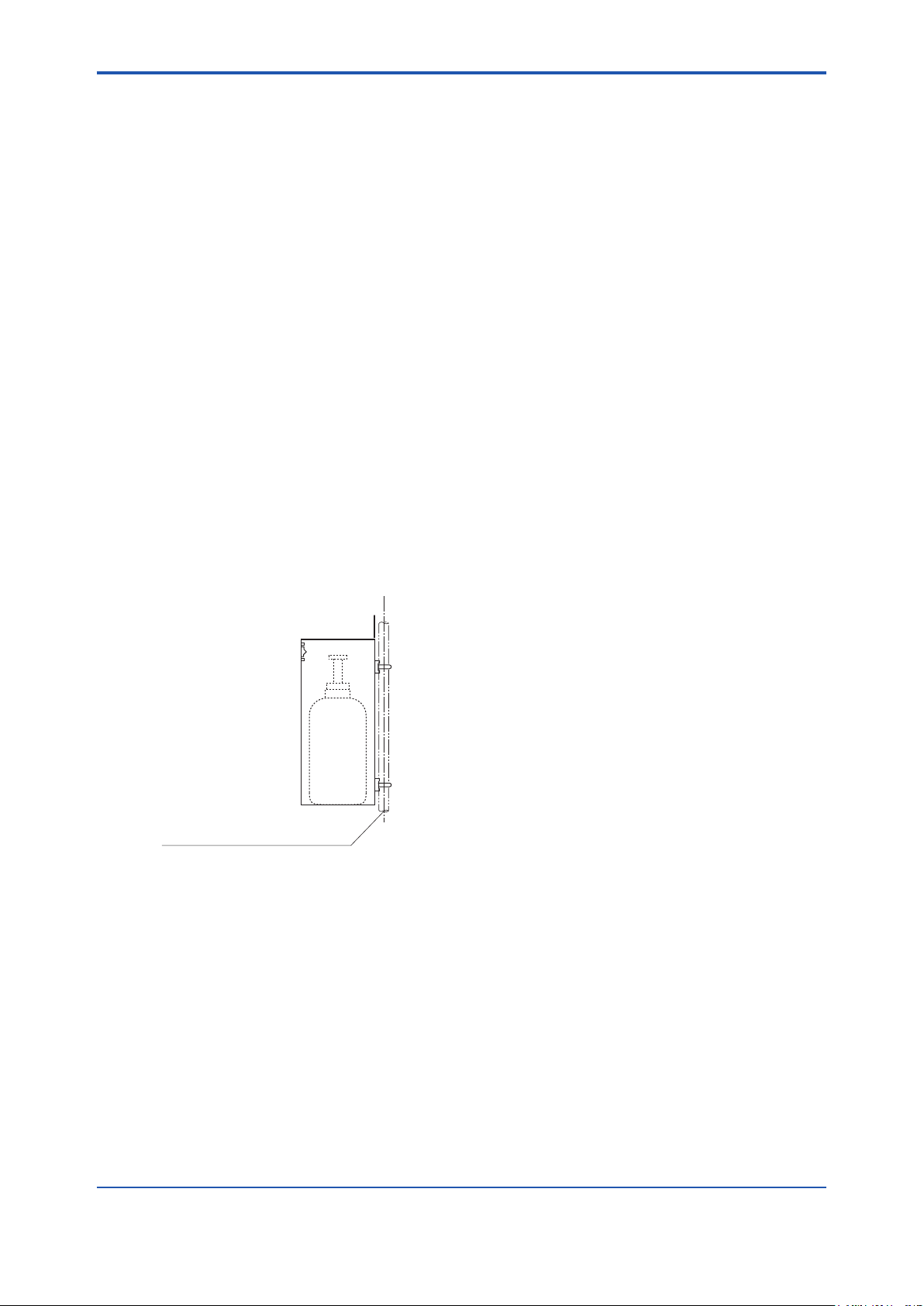
<3. Installation>
F3-16E.ai
A pipe to be mounted
(nominal JIS 50A : O.D. 60.5 mm)
3.4 Installation of the Case Assembly (E7044KF) for Calibration Gas Cylinder
The case assembly is used to store the G7001ZC zero gas cylinders.
3.4.1 Installation Location
The following should be taken into consideration:
(1) Easy access for cylinder replacement
(2) Easy access for checking
(3) Near to the detector and converter as well as the ow setting unit.
(4) The temperature of the case should not exceed 40°C due to rays of the sun or radiated heat.
(5) No vibration
3.4.2 Mounting
Mount case assembly on a pipe (nominal JIS 50 A) as follows:
(1) Prepare a vertical pipe of sufcient strength (nominal JIS 50A: O.D. 60.5 mm) for mounting
the case assembly. (The sum of the case assembly and the calibration gas cylinder weighs
approximately 4.2 kg.)
3-9
(2) Mount the case assembly on the pipe by tightening the nuts with the U-bolt so that the metal
tting is rmly attached to the pipe.
Figure 3.16 Pipe Mounting
IM 11M12A01-04E
Page 49
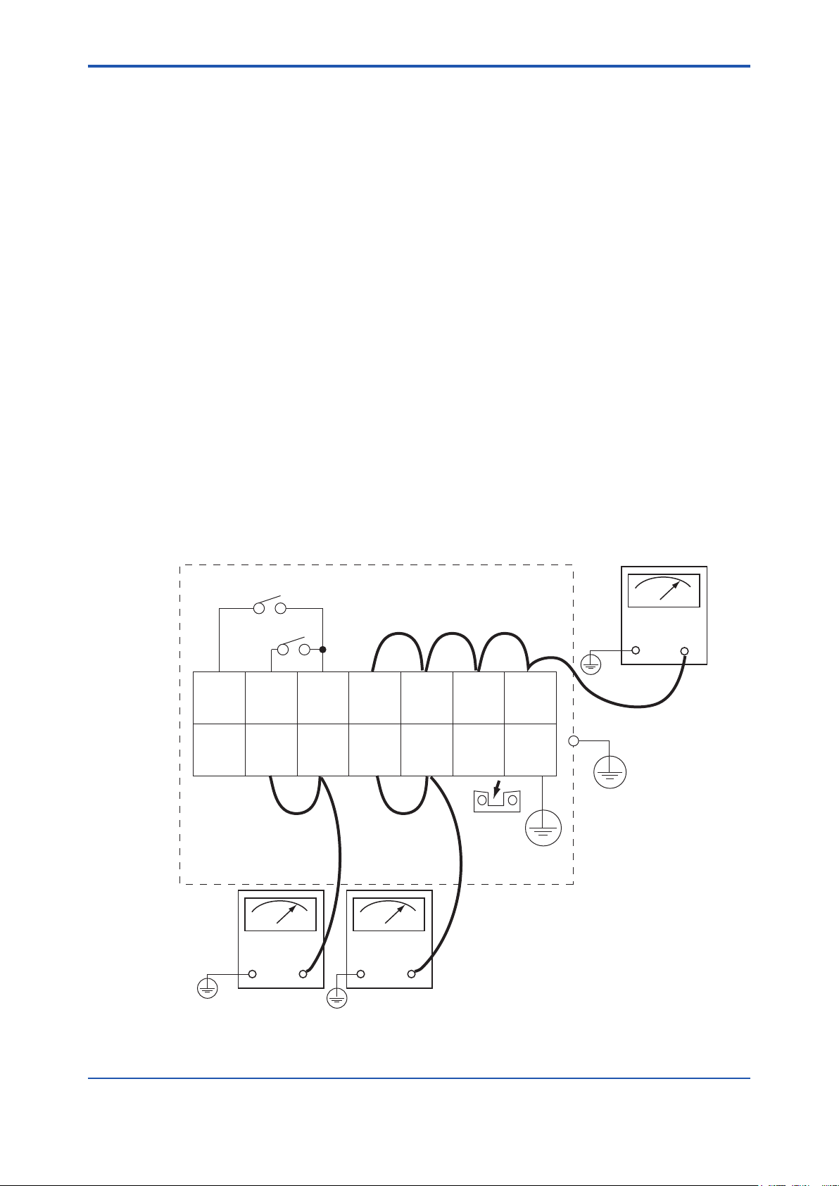
3-10
1
DI-1
2
DI-2
3
DI-C4DO-15DO-16DO-27DO-2
8
FG
9
AO
(+)
10
AO
(-)
11
L
12
N
13
G
14
FG
F3.17E.ai
Remove
jumper
plate
Insulation
resistance
tester
Insulation
resistance
tester
Crossover wiring
Crossover wiring
Contact input 1
Contact input 2
+-
+-
Insulation
resistance
tester
+-
<3. Installation>
3.5 Insulation Resistance Test
Even if the testing voltage is not so great that it causes dielectric breakdown, testing may cause
deterioration in insulation and a possible safety hazard. Therefore, conduct this test only when it is
necessary.
The applied voltage for this test shall be 500 V DC or less. The voltage shall be applied for as short a
time as practicable to conrm that insulation resistance is 20 MΩ or more.
Remove wiring from the converter and the detector.
1. Remove the jumper plate located between terminal G and the protective grounding terminal.
2. Connect crossover wiring between L and N.
3. Connect an insulation resistance tester (with its power OFF). Connect (+) terminal to the
crossover wiring, and (-) terminal to ground.
4. Turn the insulation resistance tester ON and measure the insulation resistance.
5. After testing, remove the tester and connect a 100 kΩ resistance between the crossover wiring
and ground, to discharge.
6. Testing between the heater terminal and ground, contact output terminal and ground, analog
output/input terminal and the ground can be conducted in the same manner.
7. Although contact input terminals are isolated, insulation resistance test cannot be conducted
because the breakdown voltage of the surge-preventing arrester between the terminal and
ground is low.
8. After conducting all the tests, replace the jumper plate as it was.
IM 11M12A01-04E
Page 50
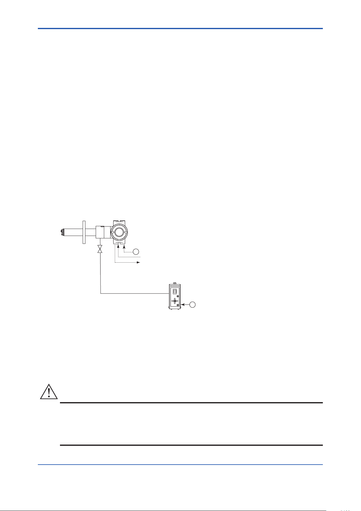
<4. Piping>
~
ZR202G Integrated type Zirconia Oxygen Analyzer
ZO21S Standard gas unit
Stop valve
Calibration gas
F1.1E.ai
~
100 to 240 V AC
100/110/115/200/220/240 V AC
Contact input
Analog output, contact output
Digital output (HART)
CAUTION
4. Piping
This chapter describes piping procedures in the three typical system congurations for EXAxt ZR
Integrated type Zirconia Oxygen Analyzer.
4-1
• Ensure that each check valve, stop valve and joints used for piping are not leaking.
Especially, when there is any leakage at piping and joints for the calibration gas, it may cause
clogging of the piping or incorrect calibration.
• Be sure to conduct leakage test after setting the piping.
• Basically, apply instrument air (dehumidied to the dew point -20°C or lower, removed any dust,
oil mist and the like) for the reference gas when piping.
• When the instrument applies natural convection for reference gas (Model ZR202GC), ambient air near the probe is used for reference gas; therefore the accuracy of analysis will
be affected by ambient humidity changes or the like. If more accurate analysis is necessary, use
instrument air (dehumidied to the dew point -20°C or lower, removed any dust, oil mist and the
like) for reference gas.
Stable analyzing can be conducted when using instrument air.
4.1 Piping for System 1
The piping in System 1 is illustrated in Figure 4.1
----
Figure 4.1 Piping for System 1
Piping in System 1 is as follows:
• Place a stop valve through the nipple at the calibration gas inlet of the equipment.
Then mount a joint for a 6 mm (O.D.) x 4 mm (I.D.) soft tube at the stop valve connection hole of
the inlet side (see Section 4.1.2). The tube is to be connected to this joint only during calibration.
• The stop valve should be connected directly to the equipment. If any piping is present between
the analyzer and the stop valve, condensed water may be produced in the pipe, which may
cause damage to the sensor by rapid cooling when the calibration gas is introduced.
• The reference gas should have an oxygen concentration identical to that of fresh air (21%).
IM 11M12A01-04E
Page 51
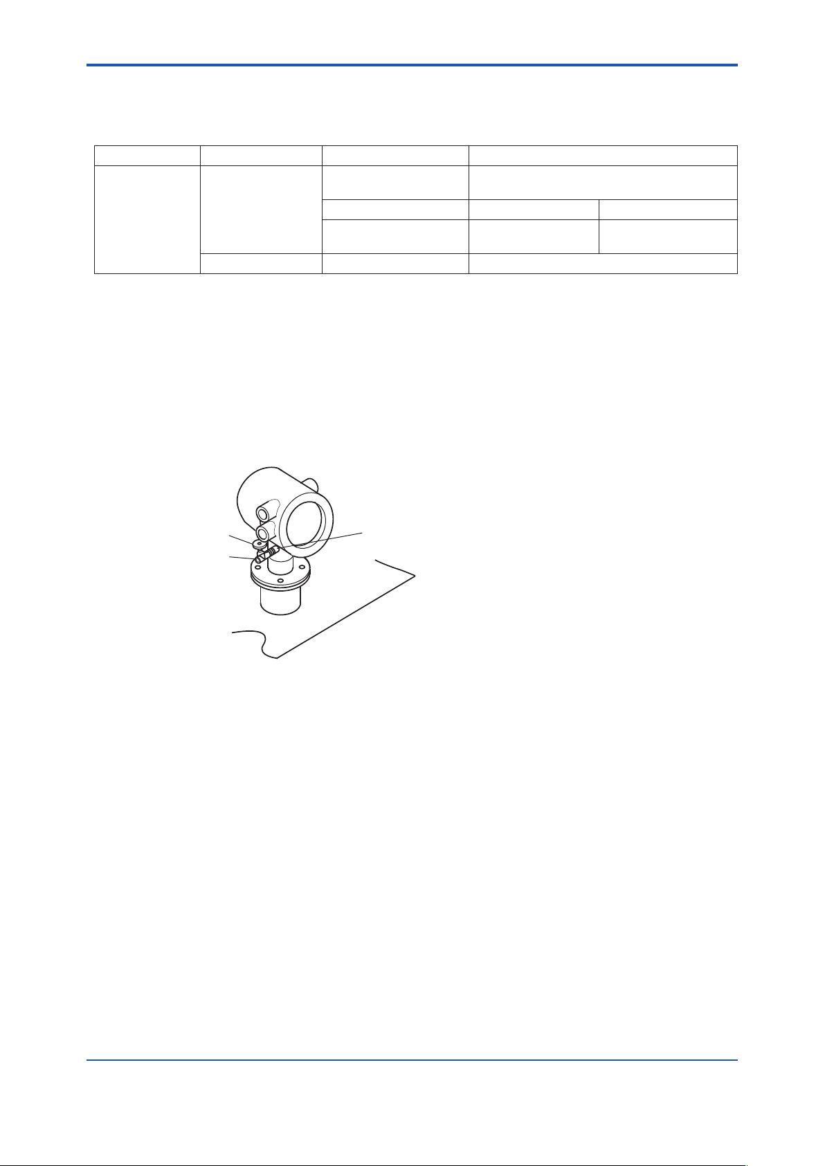
<4. Piping>
4-2
IM 11M12A01-04E
F4.2E.ai
Stop valve
Tube connection
joint
Nipple
4.1.1 Piping Parts for System 1
Check that the parts listed in Table 4.1 are provided.
Table 4.1 Piping Parts
Equipment Piping location Parts Name Description
Oxygen Analyzer Calibration gas inlet Stop valve (L9852CB or G7016XH) recommended by
YOKOGAWA
Nipple * Rc1/4 or 1/4 NPT General parts
Joint for tube connection Rc1/4 (1/4NPT) for a
6x4mm soft tube
Reference gas inlet (Sealed up) (when piping is required, refer to Section 4.1.3)
Note: Parts with marking * are used when required.
General parts can be found on the local market.
General parts
4.1.2 Piping for the Calibration Gas
When carrying out calibration, connect the piping (6(O.D) x 4(I.D.) mm tube) from the standard gas
unit to the calibration gas inlet of the oxygen analyzer. Mount the stop valve (of a quality specied by
YOKOGAWA) through a nipple (found on the local market) as illustrated in Figure 4.2, and mount a
joint (also found on the local market) at the stop valve tip. (The stop valve may be mounted on the
equipment when the oxygen analyzer is shipped.)
Note: Mount the stop valve in the vicinity of the equipment.
Figure 4.2 Piping for the Calibration Gas Inlet
4.1.3 Piping for the Reference Gas
• Normally, no piping is required for the reference gas inlet when the equipment applies natural
convection for reference gas (models ZR202G-----C). Leave the plug as it is. If the air
around the probe is polluted and the necessary oxygen concentration (21 vol%O2) cannot be
obtained, make instrument air piping as in Section 4.2, System 2.
• When the equipment uses instrument air for the reference gas, piping is required as described in
Section 4.2, System 2 (models ZR202G-----E or P).
Page 52
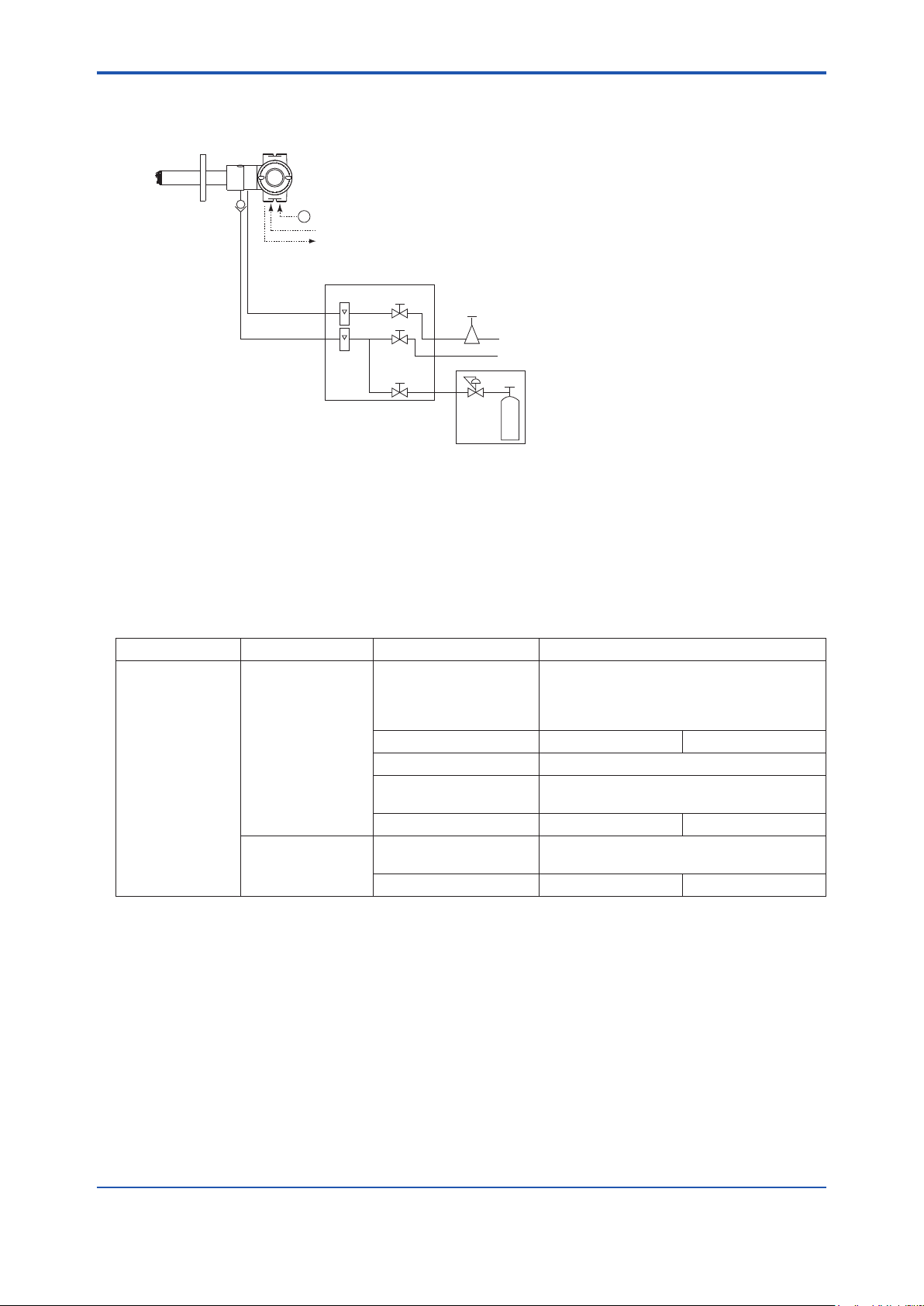
<4. Piping>
~
ZR202G Integrated type Zirconia Oxygen Analyzer
F1.2E.ai
ZA8F flow setting unit
Reference gas
Calibration gas
Needle
valve
Flowmeter
Instrument air
Air Set
Pressure
regulator
Zero gas cylinder
Calibration gas unit case
Stop valve
or
Check valve
Span gas(Same as Zero gas calibration)
100 to 240 V AC
Contact input
Analog output, contact output
Digital output (HART)
4.2 Piping for System 2
Piping in System 2 is illustrated in Figure 4.7.
Figure 4.7 Piping for System 2
4-3
System 2 illustrated in Figure 4.7 requires piping as follows:
• Mount the check valve or the stop valve through a nipple to the calibration gas inlet of the equipment.
4.2.1 Piping Parts for System 2
Check that the parts listed in Table 4.2 are provided.
Table 4.2 Piping Parts
Equipment Piping location Parts Name Description
Oxygen Analyzer Calibration gas inlet Stop valve or check valve Stop valve (L9852CB or G7016XH
recommended by YOKOGAWA
Check valve (K9292DN or K9292DS)
provided by YOKOGAWA
Nipple * Rc1/4 or 1/4 NPT General parts
Zero gas cylinder User' s scope
Pressure Regulator (G7013XF or G7014XF) recommended by
YOKOGAWA
Joint for tube connection Rc1/4 or 1/4 NPT General parts
Reference gas inlet Air set (G7003XF/ K9473XK or G7004XF
/ K9473XG) recommended by YOKOGAWA
Joint for tube connection Rc1/4 or 1/4 NPT General parts
Note: Parts with marking * are used when required.
General parts can be found on the local market.
4.2.2 Piping for the Calibration Gas
This piping is to be installed between the zero gas cylinder and the ZA8F ow setting unit, and
between the ZA8F ow setting unit and the ZR202G analyzer.
The cylinder should be placed in a case assembly E7044KF or the like to avoid any direct sunlight or
radiant heat so that the gas cylinder temperature may not exceed 40°C.
Mount the pressure regulator (recommended by YOKOGAWA) on the cylinder.
Mount the stop valve or the check valve (recommended by YOKOGAWA) through the nipple (found
on the local market) at the calibration gas inlet of the equipment as illustrated in Figure 4.8. (The stop
valve or the check valve may have been mounted on the equipment when shipped.) Connect the
ow setting unit and the analyzer to a 6mm (O.D.) x 4mm (I.D.) (or nominal size 1/4 inches) or larger
stainless steel pipe.
IM 11M12A01-04E
Page 53

<4. Piping>
4-4
IM 11M12A01-04E
F4.8E.ai
Stop valve or check valve
Piping for the reference gas
6mm (O.D.) by 4mm (I.D.)
stainless steel pipe
Piping for the calibration gas
6mm (O.D.) by 4mm (I.D.)
stainless steel pipe
~
100 to 240 V AC
Automatic Calibration Unit
Reference gas
Calibration gas (Zero)
Contact input
Analog output, contact output
Digital output (HART)
Air Set
Instrument air
Calibration gas unit case
Pressure
regulator
Zero gas cylinder
ZR202G Integrated type Zirconia Oxygen Analyzer
with automatic calibration
F1.3E.ai
Span gas
ZR20H
Note:
The installation temperature limits range for integrated type analyzer is -20 to 55°C.
Figure 4.8 Piping for the Calibration Gas Inlet
4.2.3 Piping for the Reference Gas
Reference gas piping is required between the air source (instrument air) and the ow setting unit, and
between the ow setting unit and the analyzer.
Insert the air set next to the ow setting unit in the piping between the air source and the ow setting
unit.
Use a 6mm (O.D.) x 4mm (I.D.) (or nominal size 1/4 inches) stainless steel pipe between the ow
setting unit and the analyzer.
4.3 Piping for System 3
Piping in System 3 is illustrated in Figure 4.9. In System 3, calibration is automated; however, the
piping is basically the same as that of System 2. Refer to Section 4.2.
Adjust secondary pressure of both the air set and the zero gas regulator so that these two pressures
are approximately the same. The ow rate of zero and span gases (normally instrument air) are set
by a individual needle valve. After installation and wiring, check zero gas calibration contact output
(see Sec. 7.9.2), and adjust zero gas regulator and calibration gas needle valve so that zero gas ow
is within the permitted range. Next check span gas calibration contact output and adjust air set so that
span gas ow is within the permitted range.
Figure 4.9 Piping for System 3
Page 54

<4. Piping>
Zero gas inlet
Rc1/4 or 1/4NPT(Female)
Reference gas inlet
Rc1/4 or 1/4NPT(Female)
Terminal box side
Span gas inlet
Rc1/4 or 1/4NPT(Female)
166.5
258
243
214 MAX44 66.540 40
Vertical mounting on the ZR202G (-B)
F3.15E.ai
Horizontal mounting on the ZR202G (-A)
Unit: mm
Display side
Zero gas inlet
Rc1/4 or 1/4NPT(Female)
Span gas inlet
Rc1/4 or 1/4NPT(Female)
Reference gas inlet
Rc1/4 or 1/4NPT(Female)
166.5
60
45 160
66.540 40180 MAX44
Piping Diagram
SPAN IN
REF. IN
ZERO IN
F4.11E.ai
Calibration gas
Reference gas
ZR202G body
Span gas
solenoid valve
Span gas flowmeter
Reference gas flowmeter
To Air set
To Zero gas cylinder
Needle valve
Automatic Calibration Unit
Zero gas flowmeter
Zero gas solenoid valve
Check
valve
• Installation of ZR20H Automatic Calibration Unit
4-5
IM 11M12A01-04E
Page 55
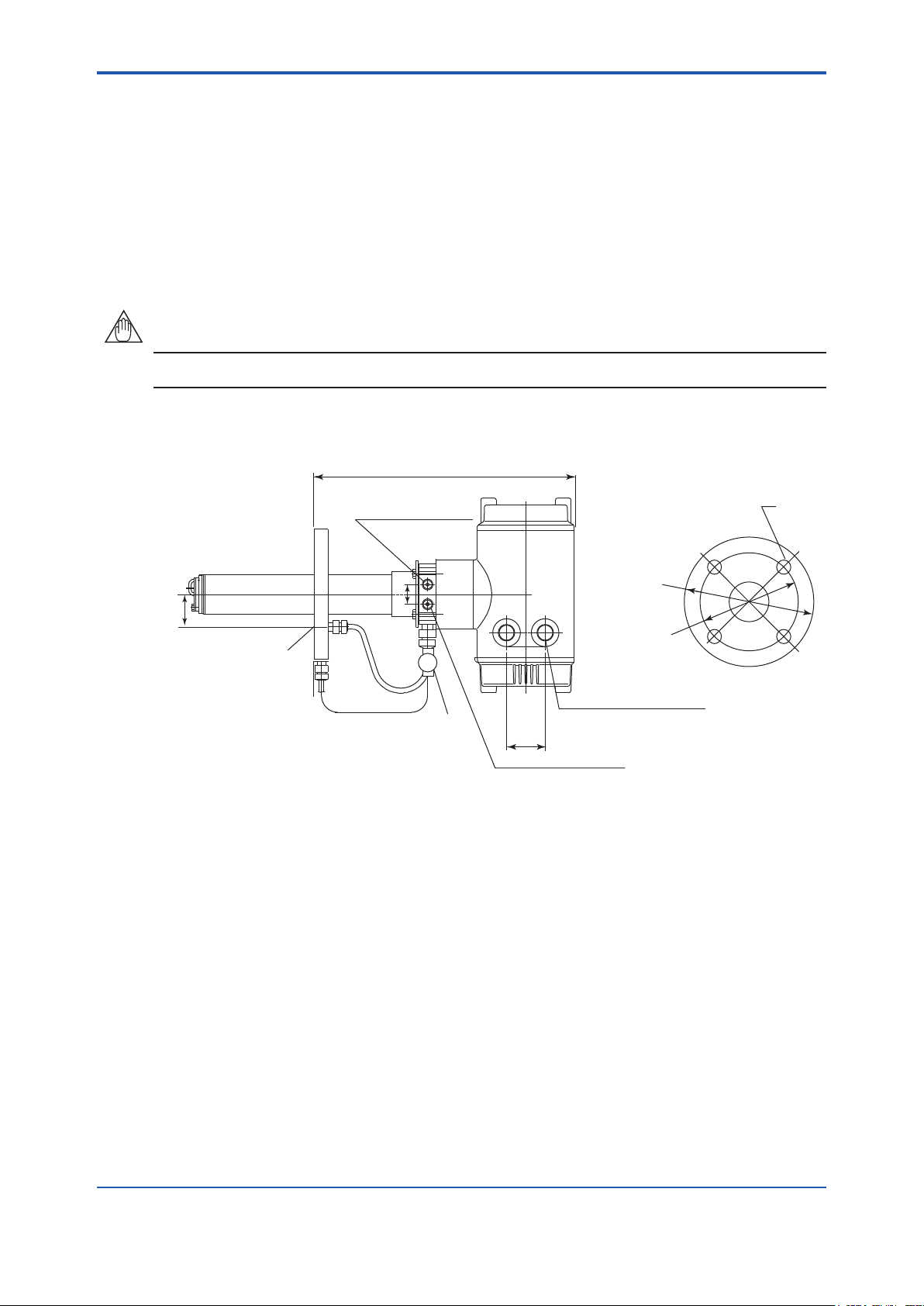
<4. Piping>
4-6
IM 11M12A01-04E
NOTE
49
342±4
25
F4.12E.ai
ØB
ØA
C
*1
*1
*1
*1
*1
*1: Dimension may vary depending on the detector type.
Ensure that the flange gasket does not block off the reference gas outlet.
Where necessary, make a notch on the flange
Rc 1/4 or 1/4 NPT
(Reference gas inlet)
4-G1/2, 2-1/2 NPT or the like
(Wiring connection)
Rc1/4 or 1/4NPT
(Calibration gas inlet)
Stop valve
Reference gas outlet
Flange
PIPING
PIPING
4.4 Piping for the Oxygen Analyzer with Pressure Compensation
ZR202G-----P Oxygen Analyzer with pressure compensation may be used in System 2 and
System 3.
Use this style analyzer whenever the furnace pressure exceeds 5 kPa (see Note). Even if the furnace
pressure is high, the detector can measure by adjusting pressure of the probe with the furnace
pressure using instrument air. The inside pressure of the probe will be kept identical to the furnace
pressure by feeding instrument air at higher pressure than that in the furnace.
The process gas pressure should not be subjected to rapid changes.
Unit: mm
The detector with pressure compensation is illustrated in Figure 4.12.
Figure 4.12 Oxygen Analyzer with Pressure Compensation
Ensure that the furnace gas does not ow into the probe.
Valve operation
1. For safety, stop the furnace that the detector is to be installed in. If furnace internal pressure is
high, this is especially dangerous.
2. Before starting instrument air ow, completely shut the stop valve in front of the reference gas
outlet.
3. Check that the reference gas outlet is not blocked by a ange gasket or the like.
Page 56
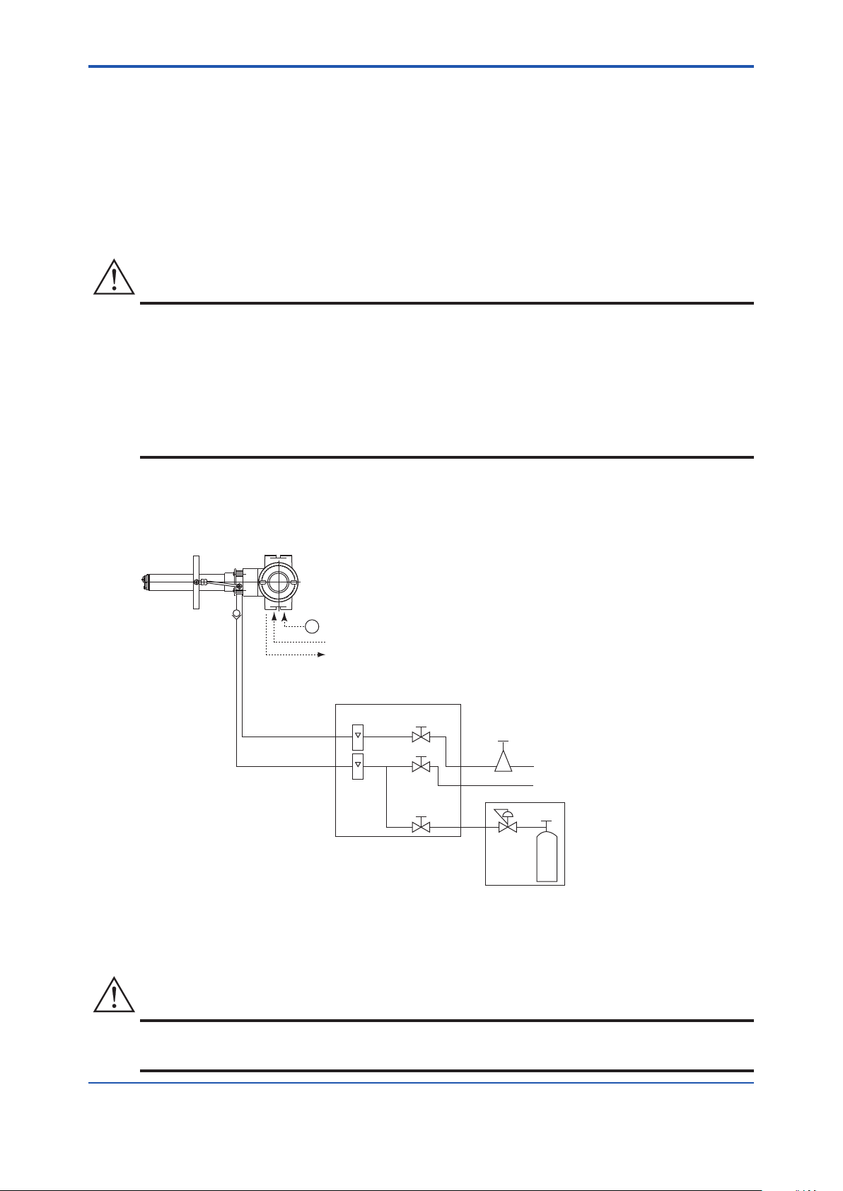
<4. Piping>
CAUTION
~
ZR202G Integrated type Zirconia Oxygen Analyzer
with pressure compensation
F1.2E.ai
ZA8F flow setting unit
Reference gas
Calibration gas
Needle
valve
Flowmeter
Instrument air
Air Set
Pressure
regulator
Zero gas cylinder
Calibration gas unit case
Stop valve
or
Check valve
Span gas(Same as Zero gas calibration)
100 to 240 V AC
Contact input
Analog output, contact output
Digital output (HART)
CAUTION
4. Set the instrument air pressure higher than furnace internal pressure.
5. Completely open the stop valve in front of the reference gas outlet and, after turning on
instrument air ow, start furnace operation. As furnace internal pressure rises, conrm that
instrument air continues to ow and adjust the valve or increase supply pressure if necessary.
6. After furnace internal pressure stabilizes, adjust ow.
7. If furnace operation is stopped, stop instrument air ow and completely shut the stop valve in
front of the reference gas outlet. You may leave reference gas owing if you wish.
• Use suitable cable glands to completely seal the detector. As far as possible do not stop the
instrument air ow, to prevent the sample gas from entering the detector and damaging the
zirconia cell.
4-7
• Connect the stop valve, which is at the calibration gas inlet, directly to the equipment.
If piping connections are made between the detector and the needle valve, condensation
will result inside the piping and cause the sensor to be damaged when the calibration gas is
introduced.
Figure 4.13 illustrates an example of System 2 using the analyzer with pressure compensation.
Supplying the air pressure (ow) may vary depending on the furnace pressure. It is recommended to
use a ow gauge and an air set meeting the furnace pressure.
Figure 4.13 Illustrates an example of System 2 using the analyzer with pressure
• When using the ZA8F Flow Setting Unit and the ZR20H Automatic Calibration Unit, please note that
compensation.
the supplying airow (pressure) will vary depending on the furnace pressure.
IM 11M12A01-04E
Page 57

4-8
<4. Piping>
4.4.1 Piping Parts for Oxygen Analyzer with Pressure Compensation
Check that the parts listed in Table 4.3 are provided.
Table 4.3 Piping Parts
Equipment Piping location Parts Name Description
Oxygen Analyzer
with pressure
compensation
Note: Use parts with marking * as required.
General parts can be found on the local market.
Calibration gas inlet Check valve or stop
valve
Nipple * Rc1/4 or 1/4 NPT General parts
Zero gas cylinder User's scope
Pressure regulator (G7013XF or G7014XF) recommended by
Joint for tube connection Rc1/4 or 1/4 NPT General parts
Reference gas inlet Air set (G7003XF/ K9473XK or G7004XF / K9473XG)
Joint for tube connection Rc1/4 or 1/4 NPT General parts
Stop valve (L9852CB or G7016XH)
recommended by YOKOGAWA
Check valve (K9292DN or K9292DS)
provided by YOKOGAWA
YOKOGAWA
recommended by YOKOGAWA
4.4.2 Piping for the Calibration Gas
Calibration gas piping is basically identical to that of System 2. See Section 4.2.2.
4.4.3 Piping for the Reference Gas
Reference gas piping is basically identical to that of for System 2. See Section 4.2.3.
IM 11M12A01-04E
Page 58

<5. Wiring>
CAUTION
NOTE
5. Wiring
This chapter describes wiring procedures necessary for the EXAxt ZR Integrated type Zirconia
Oxygen Analyzer.
5.1 General
• Never supply current to the equipment or any other device constituting a power circuit in
combination with the equipment, until all wiring is completed.
5-1
• This product complies with CE marking.
Where a performance suit for CE marking is necessary, the following wiring procedure is necessary.
1. Install an external switch or circuit breaker to the power supply of the equipment.
2. Use an external switch or circuit breaker rated 5A and conforms to IEC 947-1 or IEC 947-3.
3. It is recommended that the external switch or circuit breaker be mounted in the same room as
the equipment.
4. The external switch or circuit breaker should be installed within the reach of the operator, and
marked as the power supply switch of this equipment.
Wiring procedure
Wiring should be made according to the following procedure:
1. Be sure to connect the shield of the shielded line to FG terminal of the analyzer.
2. The most outer sheath of the signal line and the power cable should be stripped off to the
minimum necessary length.
3. Signal will be affected by noise emission when the signal lines, power cable and heater cable
are located in the same conduit. When using a conduit, signal lines should be installed in the
separate conduit from power and heater cables. Be sure to ground the metal conduit.
4. Mount the attached two blind plugs to unused cable connection gland(s) of the equipment.
5. The cables indicated in Table 5.1 are used for wiring.
After completing the wiring, screw the cover in the terminal box body and secure it with a lock screw.
6.
Table 5.1 Cable Specications
Terminal name of converter Name Need for shields Cable type Number of wires
L, N,
AO+, AO- Analog output Ο CVVS 2
DO-1, DO-2 Contact output CVV 2 to 4
DI-1, DI-2, DI-C Contact input CVV 3
Note *: When the case is used for protective grounding, use a 2-wire cable.
• Select an appropriate cable O.D. for the cable gland size.
• Protective grounding should have the grounding resistance of 100Ω or less.
Power supply CVV 2 or 3 *
IM 11M12A01-04E
Page 59
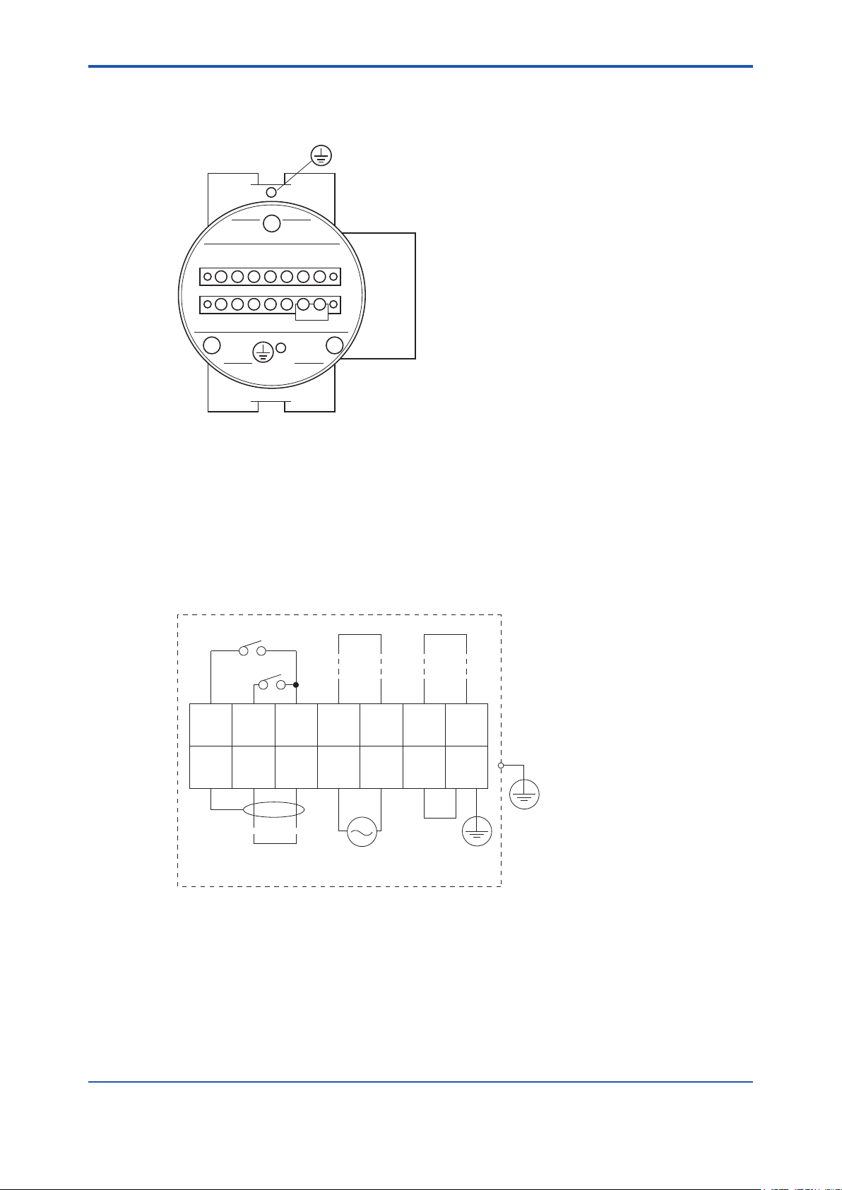
<5. Wiring>
5-2
IM 11M12A01-04E
1 2 C DO DO
DIDI
1 2
L NFG
AO
G FG
F5101.ai
–
+
1
DI-12DI-23DI-C4DO-15DO-16DO-27DO-2
8
FG
9
AO
(+)
10
AO
(-)
11
L
12
N
13
G
14
FG
F28.EPS
Model ZR202G Integrated type Zirconia Oxygen Analyzer
Contact input 1
Contact output 2
Contact output 1
Analog output
4-20 mA DC
100 to 240 V AC,
50 or 60 Hz
Digital output
Contact input 2
5.1.1 Terminals for the External Wiring
Remove the terminal cover on the opposite side of the display to gain access to the external wiring
terminals.
Figure 5.1 Terminals for External Wiring
5.1.2 Wiring
Make the following wiring for the equipment. It requires a maximum of four wiring connections as
shown below.
(1) Analog output signal
(2) Power and ground
(3) Contact output
(4) Cont
act input
The protective grounding for the analyzer shall be connected either the protective ground terminal
in the equipment or the ground terminal on the case.
Standard regarding grounding: Ground to earth, ground resistance: 100Ω or less.
Figure 5.2 Wiring Connection
Page 60

<5. Wiring>
F5.3E.ai
25
4-G1/2,2-1/2NPT etc.
Cable connection port
Cable gland
Rc1/4 or 1/4NPT
Reference gas inlet
Rc1/4 or 1/4NPT
Calibration gas inlet
+
-
AO(+)
AO(-)
FG
F5.4E.ai
Shielded cables
Analyzer
Receiver
CAUTION
5.1.3 Mounting of Cable Gland
For each wiring inlet connection of the equipment, mount the conduit appropriate for the screw size or
a cable gland.
Figure 5.3 Cable Gland Mounting
5.2 Wiring for Analog Output
This wiring is for transmitting 4 to 20mA DC output signals to a device, e.g. recorder. Maintain the load
resistance including the wiring resistance of 550Ω or less.
5-3
Figure 5.4 Wiring for Analog Output
5.2.1 Cable Specications
Use a 2-core shielded cable for wiring.
5.2.2 Wiring Procedure
(1) M4 screws are used for the terminals. Use crimp-on terminals appropriate for M4 terminal
screws for cable connections. Ensure that the cable shield is connected to the FG terminal of the
equipment.
(2) Be sure to connect (+) and (-) polarities correctly.
• Before opening the cover, loosen the lock screw. If the screw is not loosened rst, the cover
will be improperly engaged to the body, and the terminal box will require replacement. When
opening and closing the cover, remove any sand particles or dust to avoid gouging the thread.
• After screwing the cover on the equipment body, secure it with the lock screw.
IM 11M12A01-04E
Page 61

<5. Wiring>
5-4
IM 11M12A01-04E
1 2 C DO DO
DIDI
1 2
L NFG + -
AO
~
100~240VAC
50/60Hz
F5.5E.ai
Jumper plate
Grounding to the earth terminal
on the equipment case
Equipment case
Lock washer
Crimp contact of
the grounding line
Grounding
terminal
Ground
FGG
5.3 Wiring Power and Ground Terminals
Wiring for supplying power to the analyzer and grounding the equipment.
Figure 5.5 Power and Grounding Wiring
5.3.1 Wiring for Power Line
Connect the power wiring to the L and N terminals of the equipment. For a three-core cable, ground
one core appropriately. Proceed as follows:
(1) Use a two-core or three-core cable.
(2) M4 screws are used for the terminals. Use crimp-on terminals appropriate for M4 terminal
screws for cable connections.
5.3.2 Wiring for Ground Terminals
The ground wiring of the analyzer should be connected to either the ground terminal of the equipment
case or the terminal inside of the equipment. Proceed as follows:
(1) Keep the ground resistance of 100Ω or less (JIS Class D grounding).
(2) When connecting the ground wiring to the ground terminal of the equipment case, be sure that
the lock washer is in contact with the case surface (see Figure 5.5.).
(3) Ensure that the jumper plate is connected between the G terminal and the FG terminal of the
equipment.
(4) The size of external ground screw thread is M4. Each cable should be terminated corresponding
crimp-on terminals.
Page 62

<5. Wiring>
DO-1
DO-1
DO-2
DO-2
F5.6E.ai
#2 Output
Analyzer
Terminal box
Annunciator or the like
#1 Output
Converter Terminal box
DI-1
DI-C
DI-2
Contact input 1
Contact input 2
F5.7E.ai
5.4 Wiring for Contact Output
The equipment can output a maximum of two contact signals. These contact outputs can be used for
different applications such as a low alarm or high alarm.
Do the contact output wiring according to the following requirements.
Figure 5.6 Contact Output Wiring
5.4.1 Cable Specications
The number of cores varies depending on the number of contacts used.
5.4.2 Wiring Procedure
5-5
(1) M4 screws are used for the terminals. Use crimp-on terminals appropriate for M4 terminal
screws for cable connections.
(2) The contact output relays are rated 30 V DC 3A, 250 V AC 3A. Connect a load (e.g. pilot lamp
and annunciator) within these limits.
5.5 Wiring for Contact Input
The converter can execute specied function when receiving contact signals.
To use these contact signals, proceed wiring as follows:
Figure 5.14 Contact Input Wiring
5.5.1 Cable Specications
Use a 2-core or 3-core cable for this wiring. Depending on the number of input(s), determine which
cable to use.
IM 11M12A01-04E
Page 63

5-6
<5. Wiring>
5.5.2 Wiring Procedure
(1) M4 screws are used for the terminal of the converter. Each cable should be equipped with the
corresponding crimp contact.
(2) The ON/OFF level of this contact input is identied by the resistance. Connect a contact input
that satises the descriptions in Table 5.2.
Table 5.2 Identication of Contact Input ON/OFF
Resistance 200 Ω or less 100 kΩ or more
Closed Open
IM 11M12A01-04E
Page 64
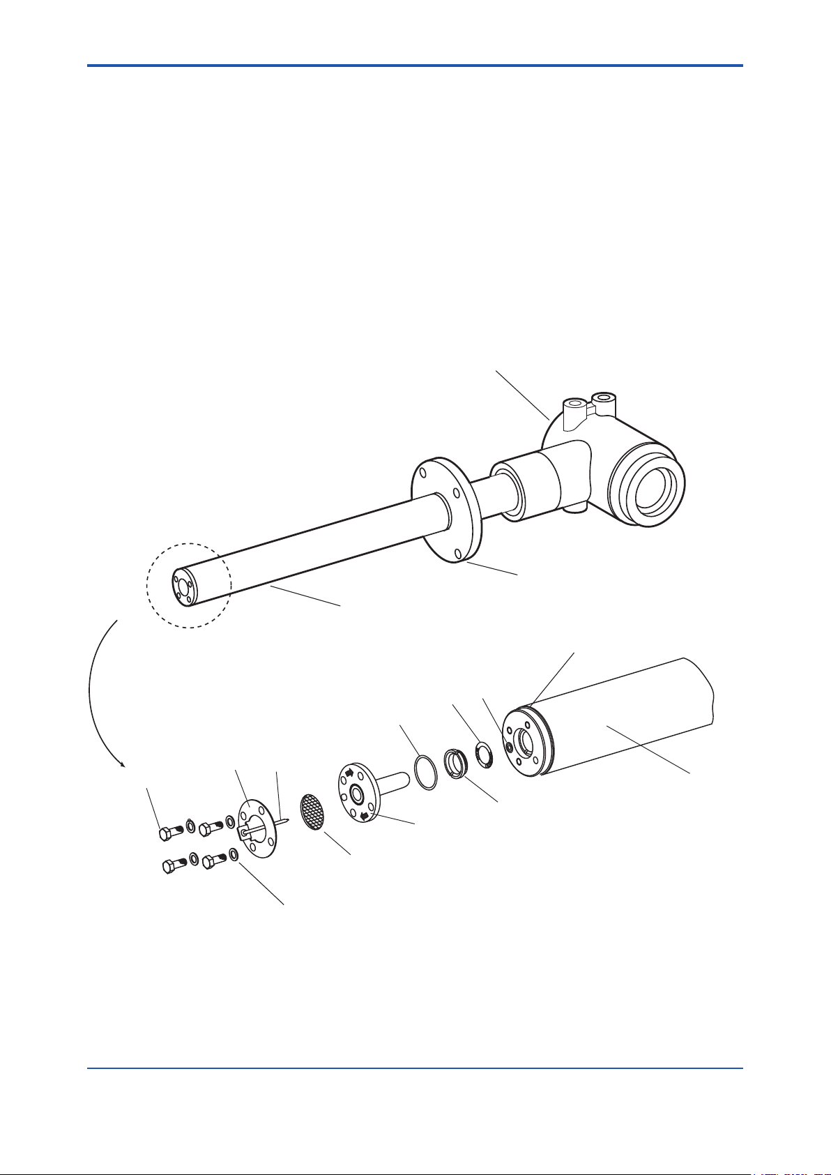
<6. Components>
Terminal box,
Non explosion-proof
JIS C0920 / equivalent to IP44D.
Equivalent to NEMA 4X/IP66
(Achieved when the cable entry is
completely sealed with a cable
gland in the recirculation pressure
compensated version.)
Probe
this part is inserted in the furnace.
Selectable of length from 0.4, 0.7,
1.0, 1.5, 2.0, 2.5 or 3.0m.
Flange
used to mount the detector.
Selectable from JIS, ANSI,
DIN or JPI standard models.
F6.1E.ai
Bolt
Washer
Pipe support
U-shaped pipe
Metal O-ring
Dust filter mounting screw
Sensor (cell)
Contact
Screw
Probe
Calibration gas
pipe opening
Filter
6. Components
This chapter describes the names and functions of components for the major equipment of the
EXAxt ZR Integrated type Zirconia Oxygen Analyzer.
6.1 ZR202G Zirconia Oxygen Analyzer
6.1.1 Integrated type Zirconia Oxygen Analyzer
6-1
Figure 6.1 Integrated type Zirconia Oxygen Analyzer
IM 11M12A01-04E
Page 65

6-2
Reference gas
flow setting valve
Span gas
flow setting valve
Zero gas
flow setting valve
Flowmeter for
reference gas
Flowmeter for
calibration gas
F6-4E.ai
ZERO INREF INSPAN IN ZERO INREF INSPAN IN
F6.3E.ai
Flowmeter for
Span gas
Flowmeter for
Span gas
Flowmeter for
Reference gas
Flowmeter for
Reference gas
Flowmeter for
Zero gas
Flowmeter for
Zero gas
Horizontal mounting Vertical mounting
Span gas
flow setting valve
Span gas
flow setting
valve
Reference gas
flow setting valve
Reference gas
flow setting valve
Zero gas
flow setting valve
Span gas
flow setting
valve
<6. Components>
6.2 ZA8F Flow Setting Unit, ZR20H Automatic Calibration Unit
Figure 6.2 ZA8F Flow Setting Unit
Figure 6.3 ZR20H Automatic Calibration Unit
IM 11M12A01-04E
Page 66
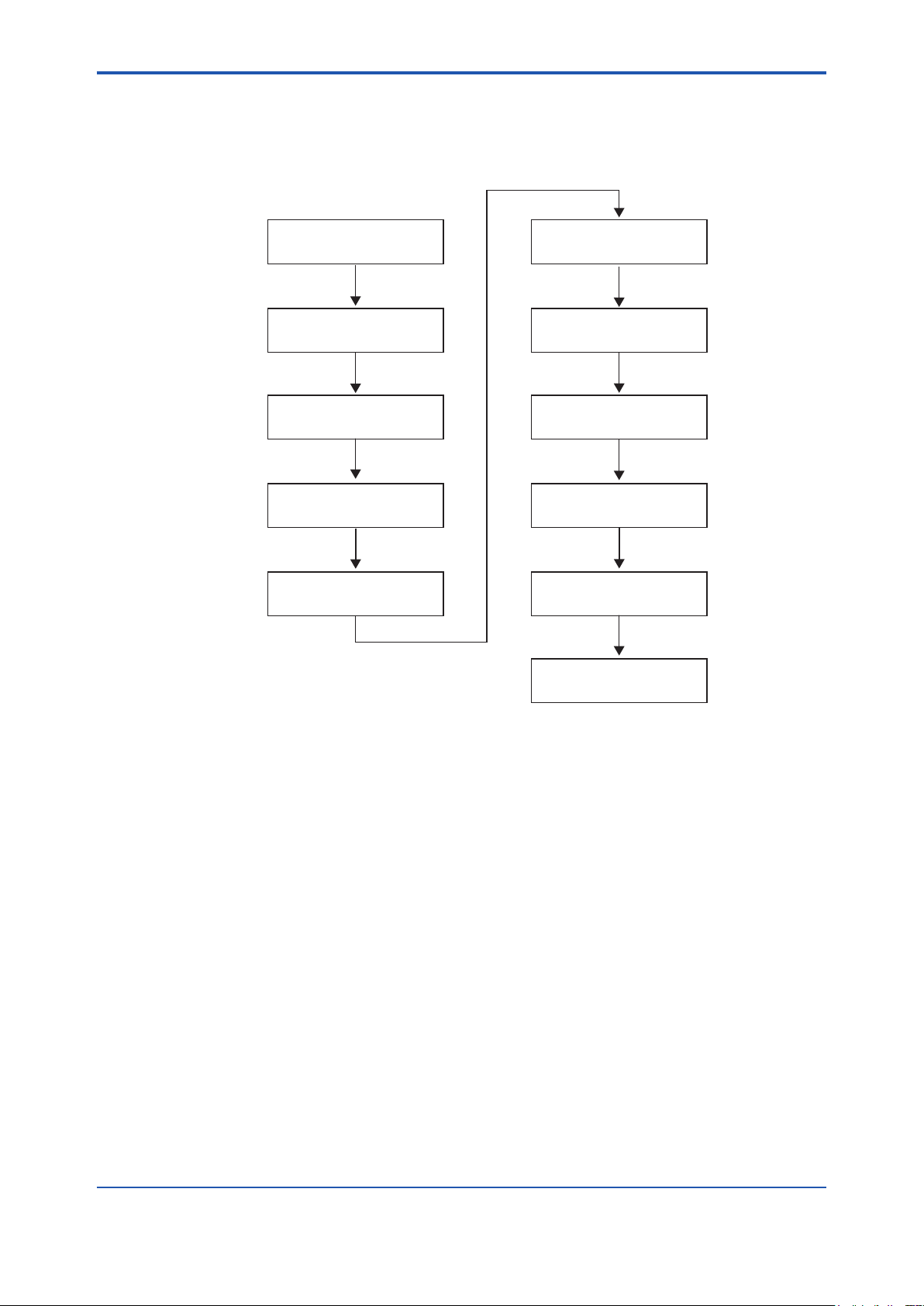
<7. Startup>
F7.0E.ai
Place in normal operation
Check piping and
wiring connections
Set up valves
Supply power
Confirm converter
type setting
Select gas to be measured
Set output ranges
Check current loop
Check contact action
Calibrate analyzer
Set detailed data
7. Startup
The following describes the minimum operating requirements — from supplying power to the
converter to analog output conrmation to manual calibration.
7-1
Figure 7.1 Startup Procedure
For system tuning by HART communication, refer to the IM 11M12A01-51E ''HART Communication
Protocol''.
IM 11M12A01-04E
Page 67
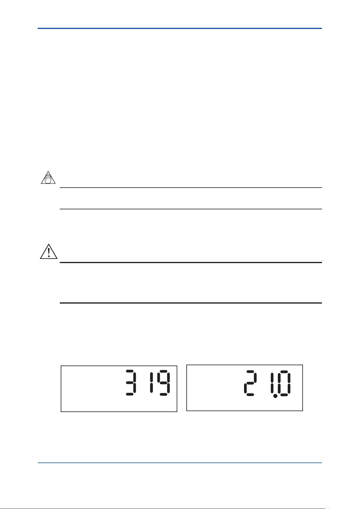
<7. Startup>
7-2
IM 11M12A01-04E
NOTE
CAUTION
%
7.1 Checking Piping and Wiring Connections
Refer to Chapters 4 and 5, earlier in this manual, for piping and wiring conrmations.
7.2 Valve Setup
Set up valves and associated components used in the analyzer system in the following procedures:
(1) If a stop valve is used in the detector’s calibration gas inlet, fully close this valve.
(2) If instrument air is used as the reference gas, adjust the Air set secondary pressure so that the
air pressure of sample gas pressure plus approx. 50 kPa (plus approx. 150 kPa for with check
valve) (300 kPa maximum for the ZA8F, 690 kPa maximum for the ZR20H) is obtained. Turn the
reference gas ow setting valve in the ow setting unit to obtain the ow of 800 to 1000 ml/min.
(Turning the valve shaft counterclockwise increases the rate of ow. When turning the valve
shaft, if the valve has a lock nut, rst loosen the lock nut.) After completing the valve setup, be
sure to tighten the lock nut.
The calibration gas ow setting will be described later. Fully close the needle valve in the ow setting
unit.
7.3 Supplying Power to Converter
To avoid temperature changes around the sensor, it is recommended that the power be continuously
supplied to the Oxygen Analyzer if it is used in an application where its operations and suspensions
are periodically repeated.
It is also recommended to ow a span gas (instrument air) beforehand.
Supply power to the converter. A display as in Figure 7.1, which indicates the detector’s sensor
temperature, then appears. As the heat in the sensor increases, the temperature gradually rises
to 750°C. This takes about 20 minutes after the power is turned on, depending somewhat on the
ambient temperature and the sample gas temperature. After the sensor temperature has stabilized
at 750°C, the converter is in the measurement mode. The display panel then displays the oxygen
concentration as in Figure 7.2. This is called the basic panel display.
Figure 7.1 Display of Sensor Temperature Figure 7.2 Measurement Mode Display
While Warming Up
Page 68
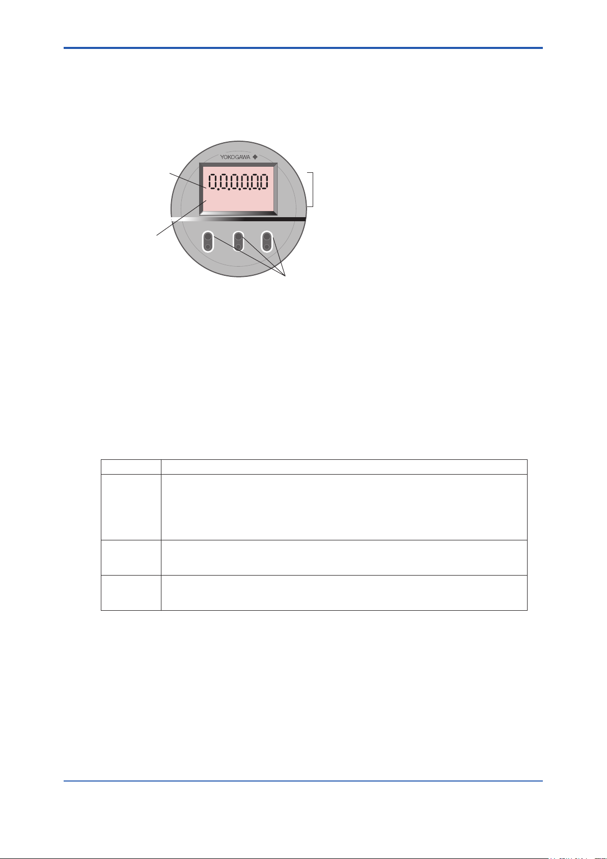
<7. Startup>
2: Infrared switch
4: Decimal point
1: Data display area
3: Engineering-unit
display area
>
>
ENT
µ Mm Nk ga lb bl %
scftm3 /d /s /h /m
F7.3E.ai
7.4 Operation of Infrared Switch
7.4.1 Display and Switches
This equipment uses an infrared switch that enables operation with the cover closed. Figure 7.3
shows the infrared switch and the display. Table 7.1 shows the three switch (keys) and functions.
Figure 7.3 Infrared switch and the display
1. Data display area: Displays the oxygen concentration, set values, alarm numbers, and error
numbers.
7-3
2. Infrared switch: Three switches perform data setting operations.
3. Engineering-unit display area: the percent sign appears when the oxygen concentration is
displayed.
4. Decimal point: A decimal point is displayed.
Table 7.1 Switch and Function
Switch Function
>
^
ENT 1. Used to change the basic panel display to the parameter selection display.
1. Moves the position of the digit to the right. If you continuously touch the key, the position
of the digit will move continuously to the right, nally returning to the leftmost position
after reaching the rightmost position of the digit.
2. Selects Yes or No.
3. When you touch this key together with the [ENT] key, the previous display then appears,
or the operation will be cancelled.
Used to change values. If you continuously touch this key, the value of the digit will increase
continuously, e.g., from 1 to 2 to 3 (for numeric data), or from A to B to C (for alphabetic
characters), and nally return to its original value.
2. Used to enter data.
3. Advances the operation.
The three infrared switches are activated by completely touching the glass surface of the switch. To
touch any of the keys continuously, rst touch the surface and then completely remove your nger
from the surface. Then touch it again.
Infrared switches consist of two elements: an infrared emitting element and an infrared acceptance
element. Infrared light-waves from the element bounces on the operator’s nger and are reected
back to the acceptance element, thereby causing the infrared switch to turn on and off, depending
on the strength of the reected light-waves. From this operating principles, carefully observe the
following:
IM 11M12A01-04E
Page 69
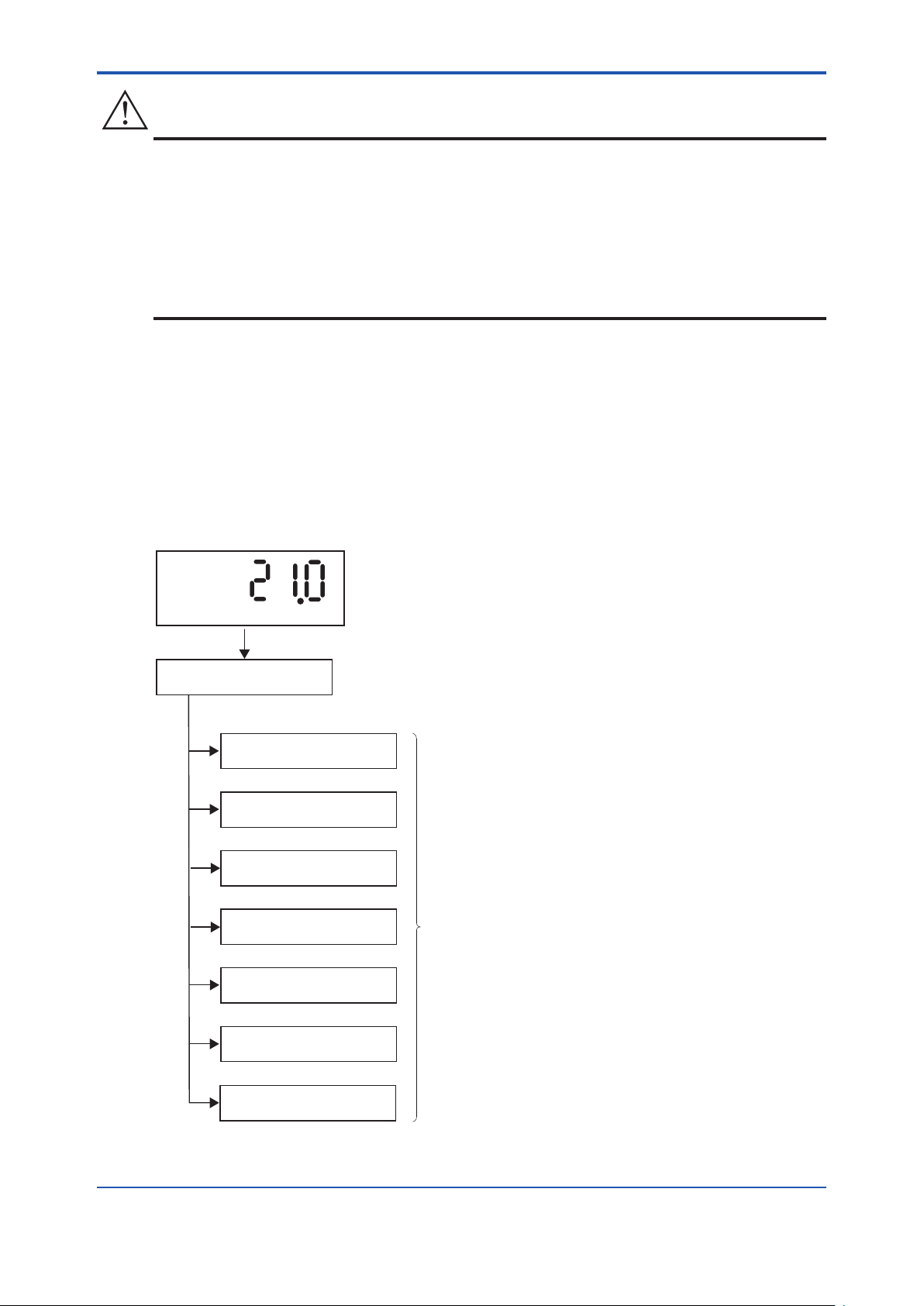
<7. Startup>
7-4
IM 11M12A01-04E
CAUTION
F7.4E.ai
Group G setup display
Basic panel display
Password entry display
Group A setup display
Group B setup display
Group C setup display
Parameter code
selection display
Group D setup display
Group E setup display
Group F setup display
%
1. Be sure to put the equipment case cover back on. If this is not done, the infrared switch will not
reect the infrared light-waves, and a “dSPErr” error will be issued.
2. Before placing the equipment in operation, be sure to wipe off any moisture or dust on the glass
surface if it is wet or dirty. Also make sure your ngers are clean and dry before touching the
glass surface of the switch.
3. If the infrared switches are exposed to direct sunlight, they may not operate correctly. In such a
case, change position of the display or install a sun cover.
7.4.2 Display Conguration
The parameter codes provided for the equipment are used to control the equipment display panels
(see below). By selecting appropriate parameter codes, you can conduct calibration and set operation
parameters. Figure 7.4 shows the conguration of display items. The parameter codes are listed in
groups of seven; which are briey described in Table 7.2.
To enter parameters, you rst need to enter the password, refer to See 7.4.3.
Touch the [ >] key and [ ENT] key at same time to revert to the main screen.
Figure 7.4 Display Conguration
Page 70
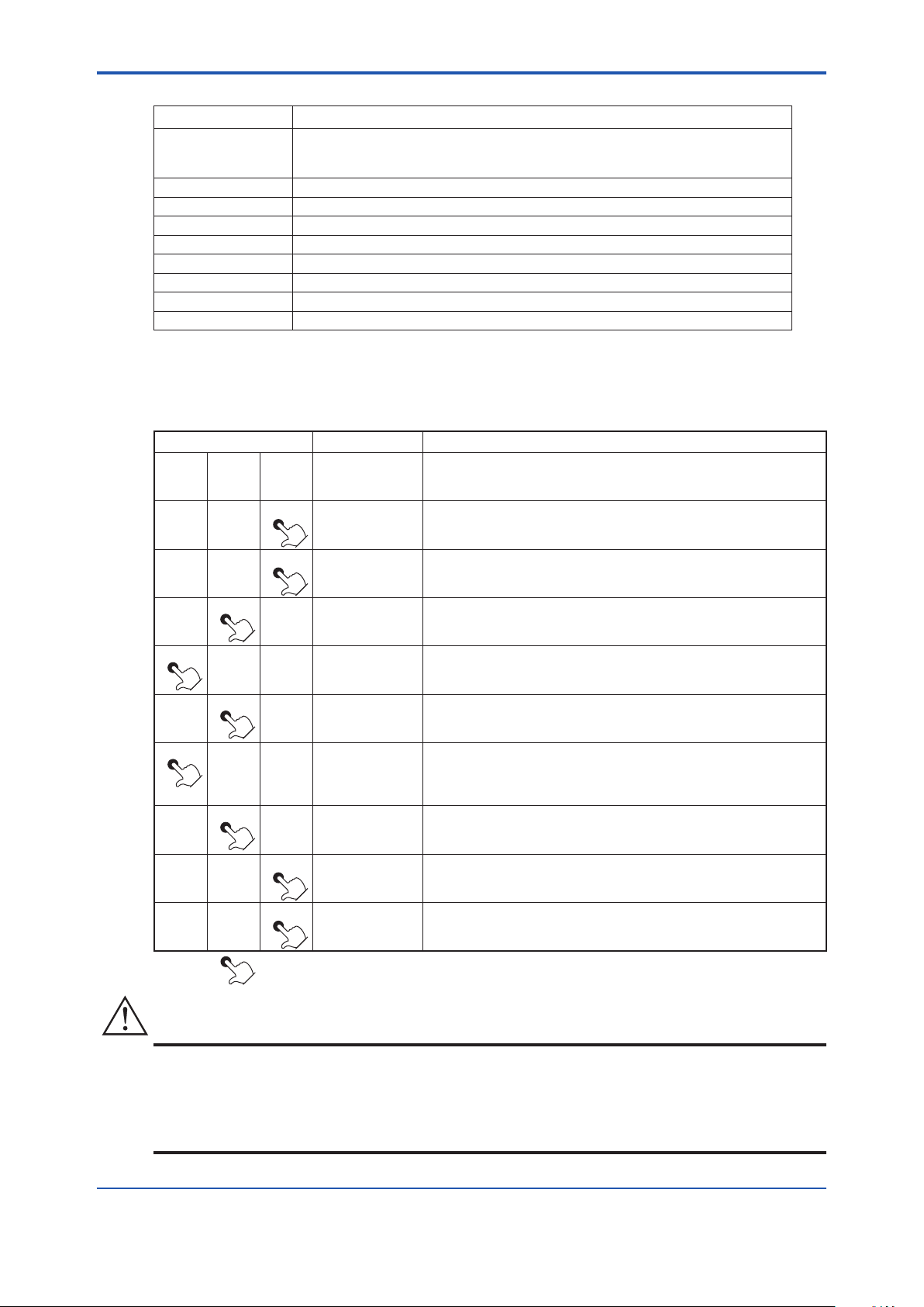
<7. Startup>
CAUTION
Table 7.2 Display Functions
Display Function and item to be set
Basic panel Displays the oxygen concentration in normal operation, or displays the detector
heater temperature while warming up. If an error or alarm arises,
the corresponding error or alarm number appears.
Password entry Enters the password for the parameter code selection display.
Group A setup Displays detailed data, such as the cell voltage or temperature.
Group B setup Sets and performs calibration.
Group C setup Sets analog output.
Group D setup Sets an alarm.
Group E setup Sets the input and output contacts.
Group F setup Selects the type of equipment and sets the parameters for computation.
Group G setup Performs the current-loop or contact checks.
7.4.3 Entering Parameter Code Selection Display
This section briey describes the password entry procedure for entering the parameter code selection
display. The password is 1102 - it cannot be changed to a different password.
Switch operation Display Description
> ∧
ENT
21.0%
Warm-up is complete, and the basic panel is now displayed.
7-5
> ∧
> ∧
>
∧
> ∧
> ∧
> ∧
> ∧
> ∧
> ∧
ENT
ENT
ENT
ENT
ENT
ENT
ENT
ENT
ENT
PASSno
0000
1000
1000
1100
1100
1102
1102
A01
Continuously touch the [ENT] key for at least three seconds
to display "PASSno."
Touch the [ENT] key again. This allows you to change the leftmost
digit that is ashing.
Set the password 1102. If you touch the [∧] key, the digit that is ashing will
be 1.
Touch the [>] key to move the position of the digit that is ashing to the
right one digit.
Touch the [∧] key to change the numeric value to 1.
Touch the [>] key again to move the position of the digit that is ashing to
the right one more digit. Continuously touch the [>] key, and the position of
the digit that is ashing will move continuously to the right.
Touch the [∧] key to change the numeric value to 2. Continuously touch [∧]
key, and the numeric value increases continuously.
If you touch the [ENT] key, all the digits ash.
Touch the [ENT] key again to display A01 on the parameter code selection
display.
The symbol [ ] indicates that the key is being touched. Light characters indicate that the digits are ashing.
• If no key is touched for at least 20 seconds during password entry, the current display will
automatically switch to the basic panel display.
• If no key is touched for at least 10 minutes during parameter code selection, the current display
will automatically switch to the basic panel display.
IM 11M12A01-04E
Page 71
<7. Startup>
7-6
IM 11M12A01-04E
7.4.4 Selecting Parameter Codes
Switch operation Display Description
> ∧
> ∧
> ∧
> ∧
> ∧
ENT
ENT
ENT
ENT
ENT
A01
A01
A01
A01
b01
Password has been entered and the parameter code selection display has
appeared.
Character A is ashing, indicating that character A can be changed.
If you touch the [>] key once, the position of the digit that is ashing will move to
the right.
This allows you to change 0.
Touch the [>] key again to move the position of the digit that is ashing to the right
one more digit. This enables you to change numeric character 1.
Touch the [>] key again to return the position of the digit that is ashing to A.
Continuously touch the [>] key, and the position of the digit that is ashing will
move continuously to the right.
If you touch the [∧] key once, character A will change to B.
> ∧
> ∧
> ∧
The symbol [ ] indicates that the key is being touched. Light characters indicates that the digits are ashing.
ENT
ENT
ENT Set
C01
d01
Value
7.4.5 Changing Set Values
(1) Selecting numeric values from among preset values
Switch operation Display Description
>
> ∧
> ∧
∧
ENT
ENT
ENT
Touch the [∧] key once to change to C.
Continuously touch the [∧] key, and the value of the digit that is ashing will
increase continuously, from D to E to F to G to A. Numeric values will change from
0 to 1 to 2 to 3 … to 8 to 9 and back to 0. However, numbers that are not present
in the parameter codes will be skipped. Each digit is changed independently. Even
though a low-order digit changes from 9 to 0, a high-order digit will not be carried.
After you select the desired character, touch the [ENT] key. The set data will be
displayed.
The set value is displayed after the parameter code selection. An example of how
0
to select either 0, 1, or 2 as the set value is given below.
(The currently set value is 0.)
Touch the [∧] key once to change the current value from 0 to 1.
1
Touch the [∧] key again to change to the numeric value 2.
2
> ∧
> ∧
ENT
ENT
0
C01
If you touch the [∧] key again, the numeric value will return to 0.
Continuously touch the [∧] key, and the numeric values will change continuously.
Display the desired numeric value and touch the [ENT] key.
The display will then return to the parameter code selection
Page 72
<7. Startup>
(2) Entering numeric values such as oxygen concentration values and factors
Switch operation Display Description
> ∧
> ∧
> ∧
> ∧
ENT
ENT
ENT
ENT
00.0
00.0
09.0
09.0
The set value is displayed after the parameter code selection.
An example of entering "9.8" is given below. (The currently set value is 0.0)
Touch the [>] key to move the position of the digit that is ashing to the digit to be
changed.
Continuously touch the [>] key, and the position of the digit that is ashing will
move continuously to the right.
Touch the [∧] key to set the numeric value 9.
Continuously touch the [∧] key, and the numeric value will change in sequence
from 0 to 1 to 2 to 3 … to 8 to 9 and back to 0.
Touch the [>] key to move the position of the digit that is ashing to the right.
7-7
> ∧
> ∧
> ∧
> ∧
(3) If invalid numeric values are entered.
Switch operation Display Description
> ∧
> ∧
> ∧
ENT
ENT
ENT
ENT
ENT
ENT
ENT
09.8
09.8
09.8
C11
98.0
Err
00.0
Touch the [∧] key to set the numeric value 8.
Where the correct numeric value is displayed, touch the [ENT] key.
If you touch the [ENT] key again, the ashing stops and the current set value will
be in effect.
Touch the [ENT] key once again to return to the parameter code selection display.
If an invalid numeric value (beyond the input range specied) is entered,
"Err" will appear for two seconds after touching the [ENT] key.
"Err" appears for two seconds, and the display returns to the rst set value.
Re-enter the numeric value.
IM 11M12A01-04E
Page 73

<7. Startup>
7-8
IM 11M12A01-04E
CAUTION
7.5 Conrmation of Equipment Type Setting
This equipment can be used for both the Oxygen Analyzer and the Humidity Analyzer. If you choose
optional specication /HS at the time of purchase, the equipment is set for the Humidity Analyzer.
Before setting the operating data, be sure to check that the desired model has been set.
Note that if the equipment type setting is changed after operating data are set, the operating data
that have been set are then initialized and the default settings remain. Set the equipment type with
parameter code 「F01」. See Table 10.7, later in this manual.
Note that if the equipment type is changed, operation data that have already been set are initialized
(reverting to the default setting).
Table 7.3 Converter Type Setting Procedure
Switch operation Display Description
> ∧
ENT
A01
Display after the password has been entered.
> ∧
> ∧
> ∧
> ∧
> ∧
> ∧
> ∧
The symbol [ ] indicates that the key is being touched. Light characters indicates that the digits are ashing.
ENT
ENT
ENT
ENT
ENT
ENT
ENT Basic
F01
F01
panel
display
Touch the [∧] key to switch to Group F. If an unwanted alphabetic character after F
has been entered, continuously touch the [∧] key to return to the original.
Touch the [ENT] key for conrmation. If 0 (zero) is entered, the oxygen analyzer
0
is already set. If 1 (one) is entered, the humidity analyzer has been set.
Change the setting following the steps below.
Continuously touch the [∧] key, and the position of the digit will change from 1 to 0
0
to 1 to 0. Release the [ENT] key when 0 is displayed.
Touch the [ENT] key. The numeric value will ash.
0
Touch the [ENT] key again to stop the numeric value from ashing.
0
Touch the [ENT] key once again, and the display will change to the parameter
code.
Touch the [>] key together with the [ENT] key to return to the basic panel display.
(This is not required if you proceed to make another setting.) (The displayed
numeric characters indicate the measurement gas concentration.)
Page 74

<7. Startup>
7.6 Selection of Measurement Gas
Combustion gases contain moisture created by burning hydrogen in the fuel. If this moisture is
removed, the oxygen concentration might be higher than before. You can select whether the oxygen
concentration in a wet gas is to be measured directly, or compensated for its dry-gas value before use.
Use the parameter code 「F02」 to set the measurement gas. For details on the parameter code, see
Table 10.7, later in this manual.
Table 7.4 Setting Measurement Gas
Switch operation Display Description
> ∧
ENT
A01
Display after the password has been entered.
7-9
> ∧
> ∧
> ∧
> ∧
> ∧
> ∧
> ∧
> ∧
> ∧
ENT
ENT
ENT
ENT
ENT
ENT
ENT
ENT
ENT Basic
F01
F01
F02
0
0
0
0
F03
panel
display
Touch the [∧] key to switch to Group F. If an unwanted alphabetic character after F
has been entered, continuously touch the [∧] key to return to the original.
Touch the [>] key to move the position of the digit that is ashing to the right.
Touch the [∧] key to change the numeric value to 2. If an unwanted numeric value
has been entered, continuously touch the [∧] key to return to the original.
Touch the [ENT] key for conrmation. If 0 (zero) is entered, the oxygen
concentration in a wet gas is already set. If the oxygen concentration in a dry gas is
to be entered, follow the steps below to set 1 (one).
Continuously touch the [∧] key, and the position of the digit will change from 1 to 0
to 1 to 0. Release the [ENT] key when 1 (one) is displayed.
Touch the [ENT] key. The numeric value will ash.
Touch the [ENT] key again to stop the value from ashing.
Touch the [ENT] key once again, and the display will change to the parameter
code selection panel.
Touch the [>] key together with the [ENT] key to return to the basic panel display.
(This is not required if you proceed to make another setting.) (The displayed
numeric characters indicate the measurement gas concentration.)
The symbol [ ] indicates that the key is being touched. Light characters indicates that the digits are ashing.
7.7 Output Range Setting
This section sets forth analog output range settings. For details, consult Section 8.2,”Current Output
Settings,” later in this manual.
7.7.1 Minimum Current (4 mA) and Maximum Current (20 mA) Settings
Use the parameter codes 「C11」 to set the oxygen concentration at 4 mA and 「C12」 to set the oxygen
concentration at 20 mA. The following shows where 10% O2 is set at 4 mA and 20% O2 at 20 mA.
IM 11M12A01-04E
Page 75

<7. Startup>
7-10
IM 11M12A01-04E
Table 7.5 Minimum and Maximum Value Setting Procedure
Switch operation Display Description
> ∧
ENT
A01
Display after the password has been entered.
> ∧
> ∧
> ∧
> ∧
> ∧
> ∧
> ∧
> ∧
> ∧
> ∧
> ∧
ENT
ENT
ENT
ENT
ENT
ENT
ENT
ENT
ENT
ENT
ENT
C01
C01
C11
000
000
010
010
010
C11
C11
C12
Set the oxygen concentration at 4 mA. Change the parameter code to C11.
Touch the [∧] key to switch to Group C.
Touch the [>] key to move the position of the digit that is ashing to the right.
Touch the [∧] key to enter the numeric value 1.
Touch the [ENT] key to display the current set value (0% O2 has been set).
Touch the [>] key to move the position of the digit that is ashing to the right.
Touch the [∧] key to change the numeric value to 1.
If you touch the [ENT] key, all the digits ash.
Touch the [ENT] key again to stop the ashing.
Touch the [ENT] key once again, and the display will switch to the parameter code
selection display.
Set the oxygen concentration at 20 mA. Touch the [>] key to move the position of
the digit that is ashing to the right.
Touch the [∧] key to enter the numeric value 2.
> ∧
> ∧
> ∧
> ∧
> ∧
> ∧
> ∧
The symbol [ ] indicates that the key is being touched. Light characters indicates that the digits are ashing.
ENT
ENT
ENT
ENT
ENT
ENT
ENT Basic
025
025
020
020
020
C12
panel
display
Touch the [ENT] key to display the current set value.
Touch the [>] key to move the position of the digit that is ashing to the right.
Touch the [∧] key to change the numeric value to 0. The numeric value will change
from 5 to 6 ... to 9 and back to 0.
If you touch the [ENT] key, all the digits ash.
Touch the [ENT] key again to stop the ashing.
Touch the [ENT] key once again to switch to the parameter code selection display.
Touch the [>] key together with the [ENT] key to return to the basic panel display.
(This is not required if you proceed to make another setting.)(The displayed
numeric characters indicate the measurement gas concentration.)
Page 76

<7. Startup>
7.8 Checking Current Loop
The set current can be output as an analog output. This enables the checking of wiring between the
converter and the receiving instrument. Current loop checking is performed using parameter code
「G01」.
Table 7.6 Checking Current Loop
Switch operation Display Description
> ∧
ENT
A01
Display after the password has been entered.
7-11
> ∧
> ∧
> ∧
> ∧
> ∧
> ∧
> ∧
The symbol [ ] indicates that the key is being touched. Light characters indicates that the digits are ashing.
ENT
ENT
ENT
ENT
ENT
ENT
ENT Basic
G01
00.0
10.0
10.0
10.0
G01
panel
display
Touch the [∧] key to switch to Group G.
Touch the [ENT] key. The output current remains preset with the output-hold
feature (Section 2.3).
Touch the [∧] key to set the numeric value 1 (to set a 10-mA output).
Touch the [ENT] key to have all the digits ash.
Touch the [ENT] key again to stop the ashing.
A 10-mA output is then issued.
Touch the [ENT] key once again to switch to the parameter code selection display.
At that point, the output current returns to the normal value.
Touch the [>] key together with the [ENT] key to return to the basic panel display.
7.9 Checking Contact I/O
Conduct a contact input and output check as well as an operation check of the solenoid valves for the
optional automatic calibration unit.
Table 7.7 Parameter Codes for Checking Contact I/O
Check item Parameter code Set value and contact action
Contact output 1 G11 0 Open
1 Closed
Contact output 2 G12 0 Open
1 Closed
Automatic calibration solenoid valve
(zero gas)
Automatic calibration solenoid valve
(span gas)
Contact input 1 G21 0 Open
Contact input 2 G22 0 Open
G15 0 Off
1 On
G16 0 Off
1 On
1 Closed
1 Closed
IM 11M12A01-04E
Page 77

<7. Startup>
7-12
IM 11M12A01-04E
CAUTION
7.9.1 Contact Output Check
Follow Table 7.8 to check the contact output. The table uses an example with contact output 1.
Table 7.8 Checking Contact Output
Switch operation Display Description
> ∧
ENT
A01
Display after the password has been entered.
> ∧
> ∧
> ∧
> ∧
> ∧
> ∧
> ∧
> ∧
> ∧
ENT
ENT
ENT
ENT
ENT
ENT
ENT
ENT
ENT Basic
G01
G01
G11
0
1
1
1
G11
panel
display
Touch the [∧] key to switch to Group G.
Touch the [>] key to move the position of the digit that is ashing to the right one
digit.
Touch the [∧] key to enter 1.
Touch the [ENT] key to have 0 (zero) ash. The contact is then open.
Touch the [∧] key to set 1 (one).
Touch the [ENT] key. The ashing continues.
Touch the [ENT] key again to stop the ashing, and the contact will be closed.
Touch the [ENT] key once again to switch to the parameter code selection display.
The contact then returns to the original state.
Touch the [>] key together with the [ENT] key to return to the basic panel display.
(This is not required if you proceed to make another setting.)
(The displayed numeric characters indicate the measurement gas concentration.)
The symbol [ ] indicates that the key is being touched. Light characters indicates that the digits are ashing.
• If you conduct an open-close check for the contact output 2, Error 1 (cell voltage failure) or Error
2 (heater temperature abnormal) will occur. This is because the built-in heater power of the
detector, which is connected to contact output 2, is turned off during the above check. So, if the
above error occurs, reset the equipment or turn the power off and then back on to restart (refer to
Section 10.4, “Reset,” later in this manual).
Page 78

<7. Startup>
7.9.2 Checking Calibration Contact Output
The calibration contacts are used for the solenoid valve drive signals for the Automatic Calibration
Unit. This output signal enables you to check the equipment operation. Check the owmeter gas ow
for that operation.
Follow the steps in Table 7.9. The table uses an example with a zero gas solenoid valve.
Table 7.9 Checking Calibration Contact Output
Switch operation Display Description
> ∧
ENT
A01
Display after the password has been entered.
7-13
> ∧
> ∧
> ∧
> ∧
> ∧
> ∧
> ∧
> ∧
> ∧
> ∧
> ∧
ENT
ENT
ENT
ENT
ENT
ENT
ENT
ENT
ENT
ENT
ENT Basic
G01
G01
G11
G11
G15
0
1
1
1
G15
panel
display
Touch the [∧] key to switch to Group G.
Touch the [>] key to move the position of the digit that is ashing to the right one
digit.
Touch the [∧] key to enter 1.
Touch the [>] key to move the position of the digit that is ashing to the right one
digit.
Touch the [∧] key to enter 5.
Touch the [ENT] key to have 0 ash.
The solenoid valve remains closed.
Touch the [∧] key to enter 1.
Touch the [ENT] key. The ashing continues.
Touch the [ENT] key again to stop the ashing, and the solenoid valve will be open
to let the calibration gas ow.
Touch the [ENT] key once again to switch to the parameter code selection display.
The solenoid valve will then be closed.
Touch the [>] key together with the [ENT] key to return to the basic panel display.
(This is not required if you proceed to make another setting.)
(The displayed numeric characters indicate the measurement gas concentration.)
The symbol [ ] indicates that the key is being touched. Light characters indicates that the digits are ashing.
IM 11M12A01-04E
Page 79

<7. Startup>
7-14
IM 11M12A01-04E
7.9.3 Checking Input Contacts
Follow Table 7.10 to check the input contacts. The table uses an example with input contact 1.
Table 7.10 Checking Input Contacts
Switch operation Display Description
> ∧
ENT
A01
Display after the password has been entered.
> ∧
> ∧
> ∧
> ∧
> ∧
> ∧
The symbol [ ] indicates that the key is being touched. Light characters indicates that the digits are ashing.
ENT
ENT
ENT
ENT
ENT
ENT Basic
G01
G01
G21
G21
panel
display
Touch the [∧] key to switch to Group G.
Touch the [>] key to move the position of the digit that is ashing to the right one
digit.
Touch the [∧] key to enter 2.
Touch the [ENT] key. 0 is displayed with the contact open. If the contact is closed,
0
the display will be 1 (one).
This enables you to check whether or not the wiring connections have been
properly made or not.
Touch the [ENT] key once again to switch to the parameter code selection display.
Touch the [>] key together with the [ENT] key to return to the basic panel display.
Page 80
<7. Startup>
CAUTION
7.10 Calibration
The converter is calibrated in such a way that the actual zero and span gases are measured and
those measured values are used to agree with the oxygen concentrations in the respective gases.
There are three types of calibration procedures available:
(1) Manual calibration conducting zero and span calibrations, or either of these calibrations in turn.
(2) Semi-automatic calibration which uses the infrared switches or a contact input signal and
conducts calibration operations based on a preset calibration time and stable time.
(3) Automatic calibration conducted at preset intervals.
Manual calibration needs the ZA8F Flow Setting Unit to allow manual supply of the calibration gases.
Semi-automatic and automatic calibrations need ZR20H Automatic Calibration Unit to allow automatic
supply of the calibration gases. The following sections set forth the manual calibration procedures.
For details on semi-automatic and automatic calibrations, consult Chapter 9, “Calibration,” later in this
manual
7.10.1 Calibration Setup
Set the following three items before carrying out a calibration. Parameter codes for these set items are
listed in Table 7.11.
7-15
(1) Mode setting
There are three calibration modes: manual, semi-automatic, and automatic.
Select the desired mode. This section uses manual mode for calibration.
(2) Oxygen concentration in zero gas
Enter the zero gas oxygen concentration for calibration.
(3) Oxygen concentration in span gas
Enter the span gas oxygen concentration for calibration. If instrument air is used, enter 21 vol %
O2. When using the ZO21S Standard Gas Unit (for use of the atmospheric air as a span gas),
use a hand-held oxygen analyzer to measure the actual oxygen concentration, and then enter it.
If instrument air is used for the span gas, dehumidify the air to a dew point of -20°C and remove any
oil mist or dust.
Incomplete dehumidifying or unclean air will have an adverse effect on the measurement accuracy.
Table 7.11 Calibration Parameter Codes
Set item Parameter code Set value
Calibration mode B03 0 Manual calibration
1 Semi-automatic calibration
2 Automatic calibration
Zero gas oxygen concentration B01 Enter oxygen concentration.
Span gas oxygen concentration B02 Enter oxygen concentration.
IM 11M12A01-04E
Page 81
<7. Startup>
7-16
IM 11M12A01-04E
Table 7.12 Calibration Setup Procedure
Switch operation Display Description
> ∧
ENT
A01
Display after the password has been entered.
> ∧
> ∧
> ∧
> ∧
> ∧
> ∧
> ∧
> ∧
> ∧
> ∧
ENT
ENT
ENT
ENT
ENT
ENT
ENT
ENT
ENT
ENT
b01
001.00
001.00
000.00
000.00
000.90
000.90
000.98
000.98
000.98
Set the zero gas concentration. Switch the parameter code to B01.
Here, set 0.98%.
Touch the [ENT] key to display the currently set value.
%
Touch the [>] key to move the position of the digit that is ashing to 1.
%
Touch the [∧] key to change to 0.
%
Touch the [>] key to move the position of the digit that is ashing to the
%
right one digit.
Touch the [∧] key to change the numeric value to 9.
%
Touch the [>] key to move the position of the digit that is ashing to the
%
right one digit.
Touch the [∧] key to change the numeric value to 8.
%
Touch the [ENT] key to have all the digits ash.
%
Touch the [ENT] key again to stop the ashing.
%
> ∧
Set the span gas concentration by above procedure, set 21 %.
> ∧
> ∧
> ∧
> ∧
> ∧
> ∧
The symbol [ ] indicates that the key is being touched. Light characters indicates that the digits are ashing.
ENT
ENT
ENT
ENT
ENT
ENT
ENT Basic panel
b01
b03
0
0
0
b03
display
Touch the [ENT] key once again to switch to the parameter code selection
display.
Next, set the calibration mode. Switch the parameter code to B03.
Touch the [ENT] key to display the currently set value.
If it is 0, you can leave it as is. If it is other than 0, change it to 0 (zero).
Touch the [ENT] key. The numeric value will ash.
Touch the [ENT] key again to stop the ashing.
Touch the [ENT] key once again to switch to the parameter code selection
display.
Touch the [>] key together with the [ENT] key to return to the basic panel
display. (This is not required if you proceed to make another setting.)
(The displayed numeric characters indicate the measurement gas
concentration.)
Page 82

<7. Startup>
7.10.2 Manual Calibration
The following describes how to conduct a calibration.
7.10.2.1 Preliminary
Before conducting a manual calibration, be sure that the ZA8F Flow Setting Unit zero gas ow valve
is fully closed. Open the zero gas cylinder pressure regulator so that the secondary pressure will be a
sample gas plus approx. 50 kPa (or sample gas pressure plus approx. 150 kPa when a check valve is
used, maximum pressure rating is 300 kPa).
7.10.2.2 Calibration Implementation
This manual assumes that the instrument air is the same as the reference gas used for the span gas.
Follow the steps below to conduct manual calibration. When using the ZO21S Standard Gas Unit (for
use of the atmospheric air as a span gas), use a hand-held oxygen analyzer to measure the actual
oxygen concentration, and then enter it.
Table 7.13 Conducting Calibration
Switch operation Display Description
> ∧
ENT
A01
Display after the password has been entered.
7-17
> ∧
> ∧
> ∧
> ∧
> ∧
> ∧
> ∧
ENT
ENT
ENT
ENT
ENT
ENT
ENT
b10
CAL
CAL
SPAn Y
21.00
%
OPEn
/20.84
20.84
%
Switch the parameter code to B10.
(The key operations for this procedure are omitted.)
Touch the [ENT] key, and "CAL" will be displayed.
To cancel the above, touch the [>] key and [ENT] key together to return to
the B10 display.
If you touch the [ENT] key again, "CAL" then ashes.
To cancel the above, touch the [>] key and [ENT] key together, the display
will return to the B10 display.
If you touch the [ENT] key again, "SPAn Y" appears (Y is ashing).
If you omit the span calibration, touch the [>] key, and change "Y" to "N".
If you touch the [ENT] key, the display then jumps to "ZEro Y."
Touch the [ENT] key to display the calibration gas value, in other words,
the span gas concentration set in Section 7.10.1, "Calibration Setup."
To cancel the above, touch the [>] key and [ENT] key together, then the
display returns to "SPAn Y."
If you touch the [ENT] key, "OPEn" and the currently measured value are
displayed alternately. Open the Flow Setting Unit span gas ow valve and
adjust the span gas ow to 600 ± 60 ml/min. To do this, loosen the valve
lock nut and gently turn the valve control (shaft) counterclockwise.
Check the calibration gas owmeter for conrmation.
If the automatic calibration unit is connected, open the span gas solenoid
valve, and the measured value changes to the span gas value.
When the display becomes stable, proceed to the next step.
To cancel the above, touch the [>] key and [ENT] key together, then the
display returns to "SPAn Y."
If you touch the [ENT] key, all the digits ash. At that point, no calibration is
conducted yet.
The symbol [ ] indicates that the key is being touched. Light characters indicates that the digits are ashing.
IM 11M12A01-04E
Page 83
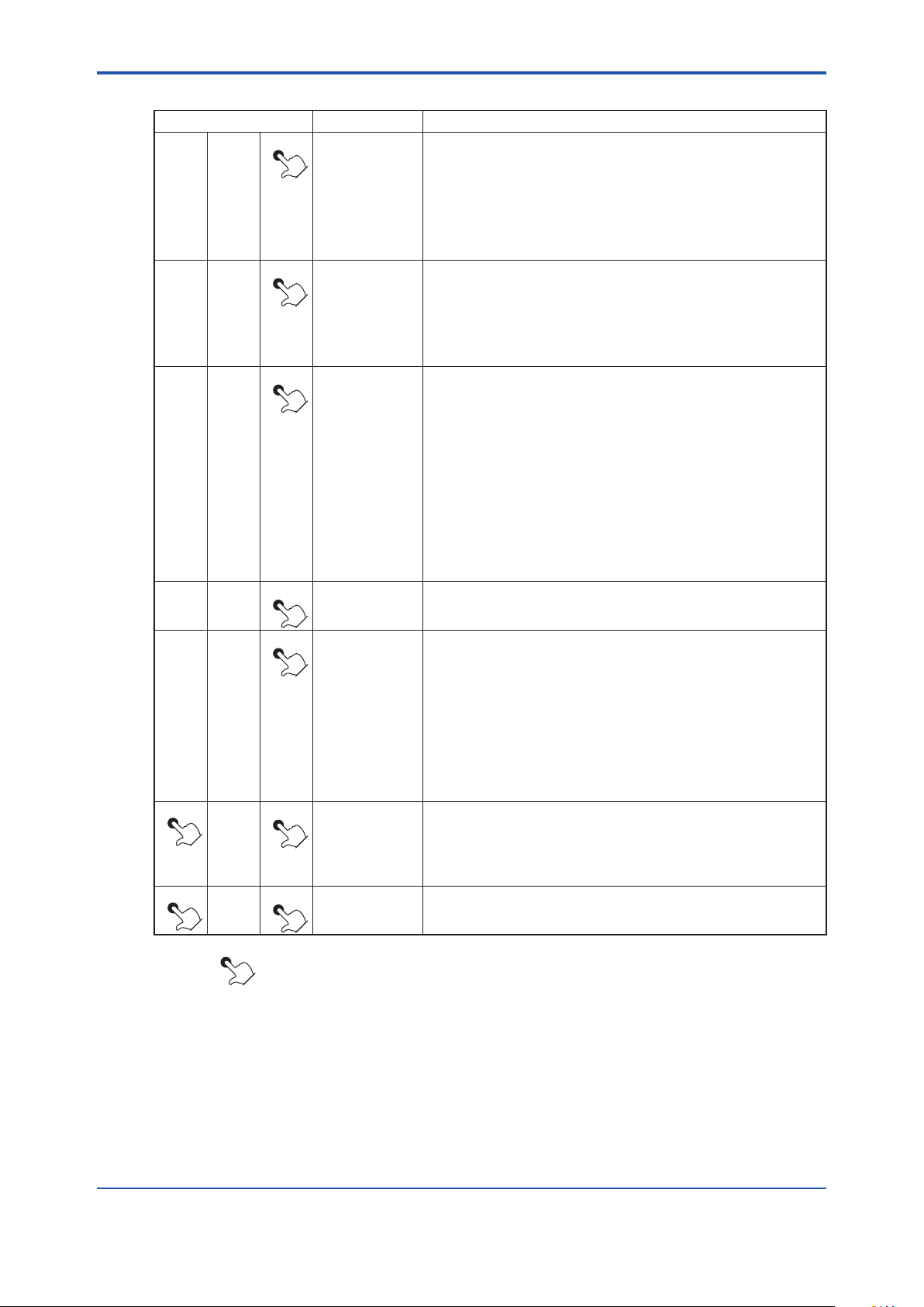
7-18
<7. Startup>
Table 7.13 Conducting Calibration (Continued)
Switch operation Display Description
> ∧
> ∧
> ∧
> ∧
> ∧
> ∧
> ∧
ENT
ENT
ENT
ZEro Y
0.98
OPEn
/0.89
ENT
ENT
ENT
ENT Basic panel
0.89
CALEnd
b10
display
If you touch the [ENT] key again, the ashing stops and "ZEro Y" appears.
Close the span gas ow valve. Secure the span gas lock nut for leakage.
If the automatic calibration unit is connected, close the span gas solenoid
valve.
If zero gas calibration is omitted, touch the [>] key to change "Y" to "N".
Next, if you touch the [ENT] key, the display jumps to "CALEnd."
Touch the [ENT] key to display the calibration gas value.
%
This value must be the zero gas concentration set in Section 7.10.1,
"Calibration Setup," earlier in this manual.
To cancel the above, touch the [>] key and [ENT] key together, then the
display returns to "ZEro Y."
If you touch the [ENT] key, "OPEn" and the currently measured value are
displayed alternately. Open the Flow Setting Unit zero gas ow valve and
adjust the zero gas ow to 600 ± 60 ml/min. To do this, loosen the valve
lock nut and gently turn the valve control (shaft) counterclockwise.
Check the calibration gas owmeter for conrmation. If the automatic
calibration unit is connected, open the zero gas solenoid valve, and then
the measured value changes to the zero gas value. When the display
becomes stable, proceed to the next step.
To cancel the above, touch the [>] key and [ENT] key together, then the
display returns to "ZEro Y."
If you touch the [ENT] key, all the digits ash. At that point, no calibration is
%
conducted yet.
Touch the [ENT] key again to get the measured value to agree with the
zero gas concentration. Close the zero gas ow valve.
Secure the valve lock nut for leakage during measurement.
If the automatic calibration unit is connected, close the span gas solenoid
valve. "CALEnd" ashes during the output hold time. If "output hold" is
specied in the Output Hold setting," it remains as an analog output (see
Section 8.3).
When the preset output hold time is up, the calibration is complete.
The output hold time is set to 10 minutes at the factory.
If you touch both the [>] key and [ENT] key at the same time during the
preset Output Hold Time, the calibration is aborted and the parameter
code selection display appears.
If you touch the [>] key and [ENT] key together, then the basic panel
display appears.
The above "display" is a result of switch operations.
The symbol [ ] indicates the keys are being touched, and the light characters indicate "ashing."
"/" indicates that the characters are displayed alternately.
IM 11M12A01-04E
Page 84
<8. Detailed Data Setting>
CAUTION
8. Detailed Data Setting
8.1 Setting Display Item
Display items are dened as items displayed on the basic panel display.
Parameter code 「A00」 or 「F08」 is used to set the display items as shown in Table 8.1. The oxygen
concentration is set at the factory before shipment. In addition, if the data initialization is performed,
the oxygen concentration will be set.
Table 8.1 Display Item
Values set with A00 or F08 Items displayed on the basic panel display
0 Indicates the oxygen concentration.
1 or 2 For humidity analyzers only. (if 1 or 2 is set for the oxygen analyzer,
"0.0" is only displayed on the basic panel display.)
3 Displays an item for the current output.
If the output damping has been set for the current output, values
involving the output damping are displayed.
8-1
If you set “3” in the parameter code 「A00」 or 「F08」, be sure to select “Oxygen Concentration” in the
following mA output setting (see Section 8.2, “Current Output Setting”).
8.2 Current Output Setting
This section describes setting of the analog output range. Table 8.2 shows parameter codes for the
set items.
Table 8.2 Current Output Parameter Codes
Set item Parameter code Set value
Analog output C01 0 Oxygen concentration
Output mode C03 0 Linear
Min. oxygen concentration C11 Oxygen concentration at 4 mA
Max. oxygen concentration C12 Oxygen concentration at 20 mA
Output damping constant C30 0 to 255 seconds
*1: For the oxygen analyzer, set 0 (zero) only for parameter code C01. When it is set, the current output is 4-mA xed regardless of
the oxygen concentration.
1 4 mA (xed *1)
2 4 mA (xed *1)
1 Logarithm
IM 11M12A01-04E
Page 85
<8. Detailed Data Setting>
8-2
IM 11M12A01-04E
CAUTION
CAUTION
8.2.1 Setting Minimum Oxygen Concentration ( at 4 mA) and Maximum Oxygen Concentration ( at 20 mA)
Set the oxygen concentration values at 4 mA and 20 mA.
The minimum concentration of oxygen for the minimum current (4 mA) is 0% O2 or 6% to 76% O2.
The maximum concentration of oxygen for the maximum current (20 mA) ranges from 5% to 100%
O2, and must be greater than 1.3 times the concentration of oxygen set for the minimum. If it does not
fall within this input range setting, the setting will be invalid, and the previous set values will remain.
Setting example 1
If the setting (for a 4 mA current) is 10% O2, you must set the oxygen concentration for the maximum
(20 mA) point at 13% O2.
Setting example 2
If the setting (for a 4 mA current) is 75% O2, you must set the oxygen concentration for the maximum
(20 mA) point at 98% O2 (75 × 1.3).
(Numbers after the decimal point are rounded up.)
• When you select logarithmic mode, the minimum output remains constant at 0.1% O2, and the
parameter 「C11」 display remains unchanged.
8.2.2 Entering Output Damping Constants
If a measured value adversely affected by a rapid change in the sample gas oxygen concentration is
used for the control means, frequent on-off actions of the output will result. To avoid this, the converter
allows the setting of output damping constants ranging from 0 to 255 seconds.
8.2.3 Selection of Output Mode
You can select a linear or logarithmic output mode. The former provides linear characteristics between
the analog output signal and oxygen concentration.
8.2.4 Default Values
When the analyzer is delivered or data are initialized, the output current settings are by default as
shown in Table 8.3.
Table 8.3 Output Current Default Values
Item Default setting
Min. oxygen concentration
Max. oxygen concentration
Output damping constant 0 (seconds)
Output mode Linear
0% O
25% O
2
2
• When you select logarithmic mode, the minimum output remains constant at 0.1% O2, and the
parameter 「C11」 display remains unchanged.
Page 86

<8. Detailed Data Setting>
8.3 Output Hold Setting
The “output hold” functions retain an analog output signal at a preset value during the equipment’s
warm-up time or calibration or if an error arises.
Table 8.4 shows the analog outputs that can be retained and the individual states.
Table 8.4 Analog Output Hold Setting
8-3
Equipment status
Output hold
values available
4 mA O
20 mA O
Without hold feature O O O
Retains output from just
before occurrence
Set value (2.4 to 21.6
mA)
O: The output hold functions are available.
*1: The output hold functions on error occurrence are unavailable when option code "/C2" or "/C3" (NAMER NE 43 compliant) is
specied.
During warm-up During
O O O
8.3.1 Denition of Equipment Status
(1) During warm-up
“During warm-up” is the time required after applying power until the sensor temperature
stabilizes at 750°C, and the equipment is in the measurement mode. This status is that the
sensor temperature is displayed on the basic panel.
(2) During maintenance
“During maintenance” is the time from when a valid password is entered in the basic panel
display to enable the parameter code selection display until the display goes back to the basic
panel display
During calibration Error occurrence
maintenance
O O O
(*1)
O
(3) During calibration (see Chapter 9, Calibration)
In the manual calibration, proceed with the calibration operation with the parameter code
「B10」 to display the span gas conrmation display for the rst span calibration, thus starting the
calibration time when the [ENT] key is touched. After a series of calibrations is complete and the
preset output stabilization time has elapsed, the calibration time will be up. Figure 8.1 shows the
denition of “during calibration” in the manual calibration.
IM 11M12A01-04E
Page 87

<8. Detailed Data Setting>
8-4
IM 11M12A01-04E
Output hold time
during calibration
Output hold time
during calibration
Switch operation Display
> ∧
ENT
b10
> ∧
> ∧
> ∧
> ∧
> ∧
> ∧
> ∧
> ∧
> ∧
> ∧
ENT
ENT
ENT
ENT
ENT
ENT
ENT
ENT
ENT
ENT
CAL
CAL
SPAn Y
21.00
%
OPEn/20.84
20.84
%
ZEro Y
0.98
%
OPEn/0.89
0.89
%
> ∧
> ∧
> ∧
Figure 8.1 Denition of During Calibration
In a semi-automatic calibration, “during calibration” is the time, starting when a calibration
instruction is executed with an infrared switch or a contact input, to make a series of calibrations,
until the preset output stabilization time elapses.
In an automatic calibration, “during calibration” is the time, starting when automatic calibration is
carried out at the calibration start time, until the preset output stabilization time elapses.
(4) “Error” appears when Error 1 to Error 4 are being issued
ENT
ENT
ENT
CALEnd
b10
Measured-value
display
Page 88

<8. Detailed Data Setting>
During error occurrence
During calibration
During maintenance
During warm-up
Preference order (high)
8.3.2E.siki
8.3.2 Preference Order of Output Hold Value
The output hold value takes the following preference order:
For example, if the output current is set to “4 mA” during maintenance, and “without hold” output
during calibration is preset, the output is held at 4 mA in the maintenance display. However, the output
hold is released at the time of starting the calibration, and the output will be held again at 4 mA after
completing the calibration and when the output stabilization time elapses.
8.3.3 Output Hold Setting
Table 8.5 lists parameter codes with set values for individual set items.
Table 8.5 Parameter Codes for Output Holding
Set items Parameter code Set value
During warm-up C04 0 4 mA
1 20 mA
2 Holds Set value
During maintenance C05 0 Without hold feature
1 Last measured value.
2 Holds set values.
During calibration C06 0 Without hold feature
1 Last measured value.
2 Holds set values.
During error occurrence C07 0 Without hold feature
1 Last measured value.
2 Holds set values.
Note: "C07" is not displayed when option code "/C2" or "/C3" (NAMUR NE 43 compliant) is specied.
8-5
8.3.4 Default Values
When the analyzer is delivered, or if data are initialized, output holding is by default as shown in Table
8.6.
Table 8.6 Output Hold Default Values
Status Output hold (min. and max. values) Preset value
During warm-up 4 mA 4 mA
Under maintenance Holds output at value just before maintenance started. 4 mA
Under calibration or blow-back Holds output at value just before starting calibration 4 mA
On Error occurrence Holds output at a preset value. 3.4 mA
IM 11M12A01-04E
Page 89
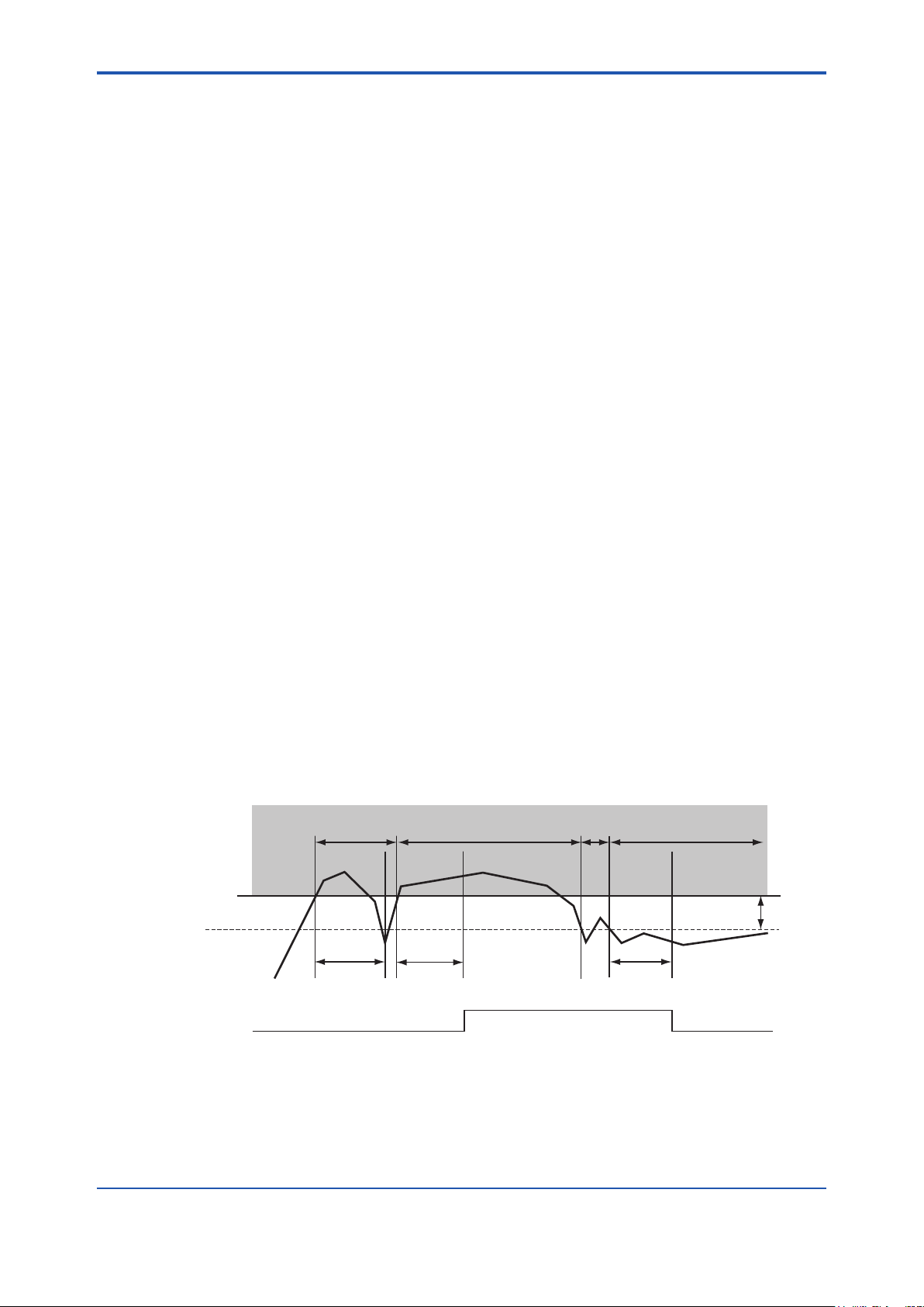
<8. Detailed Data Setting>
8-6
IM 11M12A01-04E
Delayed time:
5 seconds
7.5%
High alarm setpoint
5.5%
Oxygen concentration
Alarm output
ON
OFF
Hysteresis
2.0%
A
B
C
D
Alarm range
Delayed time:
5 seconds
Delayed time:
5 seconds
F8.2E.ai
8.4 Setting Oxygen Concentration Alarms
The analyzer enables the setting of four alarms high-high, high, low, and low-low alarms depending
upon the oxygen concentration. The following section sets forth the alarm operations and setting
procedures.
8.4.1 Alarm Values
(1) High-high and high alarm values
High-high alarms and high alarms are issued when they are set to be detected with parameter
codes 「D41」 and 「D42」, and if the measured values exceed the preset oxygen concentration
values specied with 「D01」 and 「D02」.
The oxygen alarm set values can range from 0 to 100% O
(2) Low and low-low alarm values
Low alarms and low-low alarms are issued when they are set to be detected with parameter
codes 「D43」 and 「D44」, and if the measured values are lower than the preset oxygen
concentration values specied with 「D03」 and 「D04」.
The oxygen alarm set values can range from 0 to 100%
8.4.2 Alarm Output Actions
If the measured values of the oxygen concentration uctuate between normal (steady-state) values
and alarm setting, there may be a lot of alarm-output issuing and canceling. To avoid this, set the
delay time and allow for hysteresis for alarm canceling under the alarm output conditions, as Figure
8.2 shows. When the delay time is set, an alarm will not be issued so quickly even if the measured
value differs from the steady-state and enters the alarm setpoint range. If the measured value remains
within the alarm setpoint range for a certain period of time (for the preset delay time), an alarm will
result. On the other hand, there will be a similar delay each time the measured value returns to the
steady state from the alarm setpoint range (canceling the alarm status). If hysteresis is set, alarms will
be canceled when the measured value is less than or more than the preset hysteresis values. If both
the delay time and hysteresis are set, an alarm will be issued if the measured value is in the alarm
setpoint range and the delay time has elapsed. When the alarm is reset (canceled), it is required that
the measured value be beyond the preset hysteresis value and that the preset delay time. Refer to
Figure 8.2 for any further alarm output actions. The delay time and hysteresis settings are common to
all alarm points.
.
2
O2.
Figure 8.2 Alarm Output Action
Page 90

<8. Detailed Data Setting>
CAUTION
In the example in Figure 8.2, the high alarm point is set to 7.5% O2, the delayed time is set to ve
seconds, and hysteresis is set to 2% O2.
Alarm output actions in this gure are expressed as follows:
(1) Although oxygen concentration measurement “A” has exceeded the high alarm setpoint, “A” falls
lower than the high alarm setpoint before the preset delayed time of ve seconds elapses. So,
no alarm is issued.
(2) Oxygen concentration measurement “B” exceeds the high alarm setpoint and the delayed time
has elapsed during that measurement. So, an alarm results.
(3) Although oxygen concentration measurement “C” has fallen lower than the hysteresis set value,
that measurement exceeds the hysteresis set value before the preset delayed time has elapsed.
So, the alarm is not canceled.
(4) Oxygen concentration measurement “D” has fallen below the hysteresis set value and the preset
delayed time during measurement has elapsed, so the alarm is canceled.
8.4.3 Alarm Setting
Set the alarm setpoints following Table 8.7 listing parameter codes.
Table 8.7 Parameter Codes for Oxygen Concentration Alarms
8-7
Set item Parameter code Set value
Oxygen concentration
high-high alarm setpoint
Oxygen concentration
high alarm setpoint
Oxygen concentration
low alarm setpoint
Oxygen concentration
low-low alarm setpoint
Oxygen concentration
alarm hysteresis
Delayed alarm action D33 0-255 seconds
Oxygen concentration
high-high alarm detection
Oxygen concentration
high alarm detection
Oxygen concentration
low alarm detection
Oxygen concentration
low-low alarm detection
D01 0-100% O
D02 0-100% O
D03 0-100% O
D04 0-100% O
D30 0-9.9% O
D41 0 Not detected
1 Detected
D42 0 Not detected
1 Detected
D43 0 Not detected
1 Detected
D44 0 Not detected
1 Detected
2
2
2
2
2
Even with alarms set, if “Not detected” has been set in the above alarm detection, no alarm is issued.
Be sure to set “Detected” in the above alarm detection if you use alarm features.
IM 11M12A01-04E
Page 91
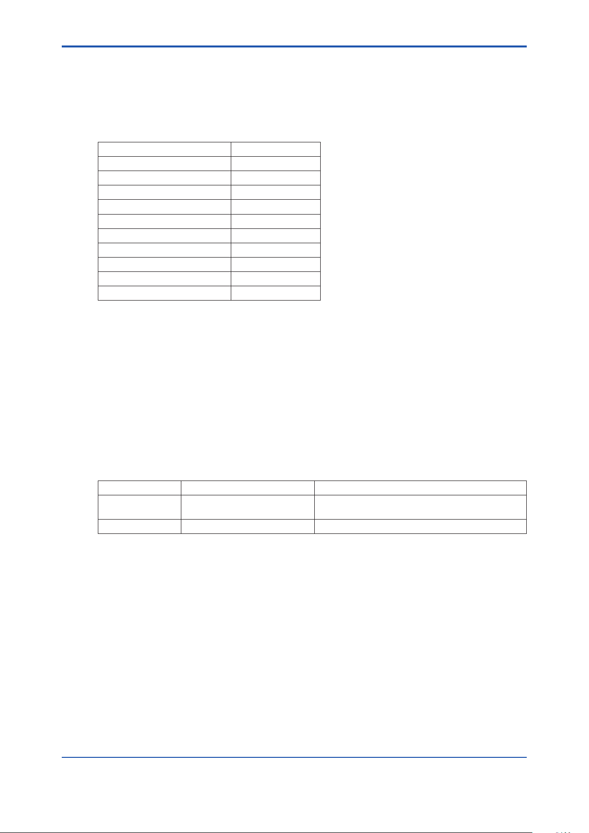
<8. Detailed Data Setting>
8-8
IM 11M12A01-04E
8.4.4 Default Values
When the analyzer is delivered, or if data are initialized, the default alarm set values are as shown in
Table 8.8.
Table 8.8 Alarm Setting Default Values
Set item Set value
High-high alarm setpoint 100% O
High alarm setpoint 100% O
Low alarm setpoint 0% O
Low-low alarm setpoint 0% O
Alarm hysteresis 0.1% O
Delayed alarm action 3 seconds
High-high alarm detection Not detected
High alarm detection Not detected
Low alarm detection Not detected
Low-low alarm detection Not detected
2
2
2
2
2
8.5 Output Contact Setup
8.5.1 Output Contact
Mechanical relays provide contact outputs. Be sure to observe relay contact ratings. (For details, see
Section 2.1, "General Specications.") The following sets forth the operation mode of each contact
output. Output contact 1 you can select open or closed contact when the contact is "operated". For
output contact 2, contact is closed. The relay for output contact 1 is energized when its contacts are
closed and vice versa. Accordingly, when no power is supplied to the equipment, those contacts
remain open. In addition, the relay for output contact 2 is energized when the corresponding contact is
open and de-energized when that contact is closed.
Table 8.9 Setting Output Contacts
Operating state When no power is applied to this equipment
Output contact 1 Open (de-energized) or closed
(energized) selectable.
Output contact 2 Closed (de-energized) only. Closed
Open
Page 92

<8. Detailed Data Setting>
WARNING
8.5.2 Setting Output Contact
Set the output contacts following Table 8.10.
Table 8.10 Parameter Codes for Output Contact Setting
8-9
Set item Parameter
code
Output contact 1
Operation E10 0 Operated in closed status. (Normally de-energized)
1 Operated when open. (Normally energized) (Note 1)
Error E20 0 Not operated if an error occurs.
1 Operated if an error occurs.
High-high alarm E21 0 Not operated if a high-high alarm occurs.
1 Operated if a high-high alarm occurs. (Note 2)
High alarm E22 0 Not operated if a high alarm occurs.
1 Operated if a high alarm occurs. (Note 2)
Low alarm E23 0 Not operated if a low alarm occurs.
1 Operated if a low alarm occurs. (Note 2)
Low-low alarm E24 0 Not operated if a low-low alarm occurs.
1 Operated if a low-low alarm occurs. (Note 2)
Maintenance E25 0 Not operated during maintenance.
1 Operated during maintenance (see Section 8.3.1).
Calibration E26 0 Not operated during calibration.
1 Operated during calibration (see Section 8.3.1).
Measurement range
change
Warm-up E28 0 Not operated during warming up.
Calibration gas
pressure
Unburnt gas
detection
decrease
E27 0 Not operated when changing ranges.
1 Operated when changing ranges. (Note 3)
1 Operated during warming up.
E29 0
E32 0 Not operated while a unburnt gas detection contact is being closed.
Not operated while a calibration gas pressure decrease contact is
being closed.
1
Operated while a calibration gas pressure
closed. (Note 4)
1
Operated while a unburnt gas detection contact is being closed. (Note 5)
Set value
decrease
contact is being
Note 1: Output contact 2 remains closed.
Note 2: The oxygen concentration alarm must be preset (see Section 8.4).
Note 3: Range change answer-back signal. For this action, the range change must be preset during the setting of input contacts
(see Section 8.6).
Note 4: Calibration gas pressure decrease answer-back signal. Calibration gas pressure decrease must be selected beforehand
during the setting of input contacts.
Note 5: Non-combusted gas detection answer-back signals. “Non-combusted gas” detection must be selected during the setting of
input contacts.
• Output contact 2 is linked to the detector’s heater power safety switch. As such, if output
contact 2 is on, the heater power stops and an Error 1 (cell voltage abnormal) or Error 2 (heater
temperature abnormal) occurs.
IM 11M12A01-04E
Page 93

<8. Detailed Data Setting>
8-10
IM 11M12A01-04E
NOTE
8.5.3 Default Values
When the analyzer is delivered, or if data are initialized, output contacts are by default as shown in
Table 8.11.
Table 8.11 Output Contact Default Settings
Item Output contact 1 Output contact 2
High-high alarm
High alarm
Low alarm
Low-low alarm
Error O
Warm-up O
Output range change
Calibration
Maintenance O
High limit temperature alarm
Calibration gas pressure
Unburnt gas detection
Operating contact status Open Closed (xed)
O: Present
decrease
The above blank boxes indicate the items have been set off.
Page 94

<8. Detailed Data Setting>
CAUTION
8.6 Input Contact Settings
The converter input contacts execute set functions by accepting a remote (contact) signal. Table 8.12
shows the functions executed by a remote contact signal.
Table 8.12 Input Contact Functions
Set item Function
Calibration gas pressure
decrease
Measuring range change While contact input is on, the analog output range is switched to 0-25% O2.
Calibration start If a contact signal is applied, semi-automatic calibration starts (only if the semi-
Unburnt gas detection If a contact signal is on, the heater power will be switched off. (An one-to 11-
While a contact signal is on, neither semi-automatic nor automatic calibrations
can be made.
automatic or automatic mode has been setup). Contact signal must be applied
for at least one second. Even though a continuous contact signal is applied, a
second calibration cannot be made. If you want to make a second calibration,
turn the contact signal off and then back on.
second time interval single-output signal is available as a contact signal.) If this
operation starts, the sensor temperature decreases and an error occurs. To
restore it to normal, turn the power off and then back on, or reset the analyzer.
8-11
• Measurement range switching function by an external contact input is available for analog output
1 only and the range is xed to 0-25%O2.
• To conduct a semi-automatic calibration, be sure to set the Calibration setup mode to “Semiautomatic” or “Automatic”.
8.6.1 Setting Input Contact
To set the input contacts, follow the parameter codes given in Table 8.13.
Table 8.13 Parameter Codes for Input Contact Settings
Set item Parameter code Set value
Input contact 1 (function) E01 0 Invalid
Input contact 2 (function) E02 0 Invalid
Input contact 1 (action) E03 0 Operated when closed
Input contact 2 (action) E04 0 Operated when closed
1 Calibration gas pressure decrease
2 Measuring range change
3 Calibration
4 Unburnt gas detection
1 Calibration gas pressure decrease
2 Measuring range change
3 Calibration
4 Unburnt gas detection
1 Operated when open
1 Operated when open
8.6.2 Default Values
When the analyzer is delivered, or if data are initialized, the input contacts are all open.
IM 11M12A01-04E
Page 95

<8. Detailed Data Setting>
8-12
IM 11M12A01-04E
8.7 Other Settings
8.7.1 Setting the Date-and-Time
The following describe how to set the date-and-time. Automatic calibration works following this setting.
Use parameter code 「F10」 to set the date-and-time.
Table 8.14 Data-and-time Settings
Switch operation Display Description
> ∧
ENT
F10
Select the parameter code F10.
> ∧
> ∧
> ∧
> ∧
> ∧
> ∧
> ∧
> ∧
>
∧
ENT
ENT
ENT
ENT
ENT
ENT
ENT
ENT
ENT
00.01.01
00.01.01
00.06.01
00.06.01
00.06.21
00.06.21
07.18
14.30
14.30
If you touch the [ENT] key, the current date will be displayed. The display
on the left indicates the date - January 1, 2000. To set June 21, 2000,
follow the steps below:
Touch the [>] key to move the position of the digit that is ashing to the
right.
Touch the [∧] key to change to 6.
Touch the [>] key to move the position of the digit that is ashing to the
right one digit.
Touch the [∧] key to change to 2.
Touch the [>] key to move the position of the digit that is ashing to the
right one digit.
Let the rightmost character ash, and touch the [>] key to display the time.
Continuously touch the [>] key, then the date and time are alternately
displayed. Displayed on the left is 7:18 a.m.
Omitted here.
Touch the [∧] key and enter the current time in same way as the date has
been entered, on a 24-hour basis. 2:30 p.m.
Displayed on the left means 2:40 p.m.
If you touch the [ENT] key, all the digits ash.
> ∧
> ∧
The symbol ( ) indicates that the corresponding keys are being touched, and the light characters indicate ashing.
ENT
ENT
14.30
F10
Touch the [ENT] key again to set the time.
If you touch the [>] and [ENT] keys together, the parameter code selection
display appears.
Page 96

<8. Detailed Data Setting>
8-13
8.7.2 Setting Periods over which Average Values are Calculated and Periods over which Maximum and Minimum Values Are Monitored
The equipment enables the display of oxygen concentration average values and maximum and
minimum values under measurement (see Section 10.1, later in this manual). The following section
describes how to set the periods over which oxygen concentration average values are calculated and
maximum and minimum values are monitored.
8.7.2.1 Procedure
Use the parameter-code table below to set the average, maximum and minimum oxygen
concentration values. Periods over which average is calculated and periods over which maximum and
minimum values are monitored can be set, ranging from 1 to 255 hours. If the set ranges are beyond
the limits specied, an “Err” will be displayed.
Table 8.15 Parameter Codes for Average, Maximum and Minimum Values
Set item Parameter code Set range Units
Periods over which average values
are calculated
Periods over which maximum
and minimum values are monitored
F11 1 to 255 Hours
F12 1 to 255 Hours
8.7.2.2 Default Value
When the analyzer is delivered, or if data are initialized, periods over which average values are
calculated are set to one hour, and periods over which maximum and minimum values are monitored
are set to 24 hours.
IM 11M12A01-04E
Page 97
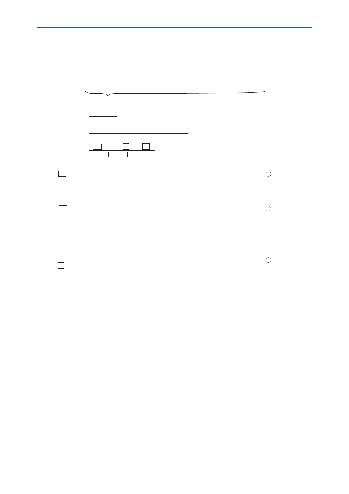
<8. Detailed Data Setting>
8-14
IM 11M12A01-04E
Moisture quantity =
=
=
=
where,
Ao : Theoretical amount of air per unit quantity of fuel, m3 /kg (or m3 /m3 ) ............ 2 in Table 8.16
G: Actual amount of exhaust gas (including water vapor) per unit quantity of fuel,
m3/kg (or m3 /m3)
Gw : Water vapor contained in exhaust gas per unit quantity of fuel (by hydrogen
and moisture content in fuel), m3 /kg (or m3 /m3 ) ............ 1 in Table 8.16
Gw1: Water vapor contained in exhaust gas per unit quantity of fuel (moisture content
in air), m3 /kg (or m3 /m3 )
Go: Theoretical amount of dry exhaust gas per unit quantity of fuel, m3 /kg (or m3 /m3 )
m: Air ratio
X : Fuel coefficient determined depending on low calorific power of fuel, m3 /kg (or m3 /m3 ) ... 3 in Table 8.16
Z : Absolute humidity of the atmosphere, kg /kg ....... Figure 8.4
(water vapor caused by combustion and water vapor contained in the exhaust gas)
.
.
actual exhaust gas(including water vapor) per fuel
+ (water vapor contained in air for combustion)
x 100
Gw + (1.61 x Z x m x Ao)
Go + Gw + (m - 1) Ao + (1.61 x Z x m x Ao)
x 100
Gw + (1.61 x Z x m x Ao )
X + Ao x m
x 100
Gw + Gw1
G
x 100
..... Equation 1
............ Equation 2
8.7.3 Setting Fuels
8.7.3.1 Input Parameters
The analyzer calculates the moisture content contained in exhaust gases. The following sets forth
the fuel parameters necessary for calculation and their entries. The moisture quantity may be
mathematically expressed by:
Fill in the boxes with fuel parameters in Equation 2 above to calculate the moisture content. Use Ao,
Gw and X shown in Table 8.16. If there are no appropriate fuel data in Table 8.16, use the following
equations for calculation.
Find the value of “Z” in Equations 1 and 2 using Japanese Standard JIS B 8222. If a precise
measurement is not required, obtain the value of “Z” using a graph for the absolute humidity indicated
by a dry and wet bulb hygrometer.
Page 98

<8. Detailed Data Setting>
For liquid fuel
Amount of water vapor in exhaust gas (Gw) = (1/100) {1.24 (9h + w)} (m /kg)
Theoretical amount of air (Ao) = 12.38 x (Hl/10000) – 1.36 (m /kg)
Low calorific power = Hl
X value = (3.37 / 10000) x Hx – 2.55 (m /kg)
where, Hl: low calorific power of fuel
h: Hydrogen in fuel (weight percentage)
w: Moisture content in fuel (weight percentage)
Hx: Same as numeric value of Hl
For gas fuel
Amount of water vapor in exhaust gas (Gw) = (1/100) {(h2) + 1/2 ∑y (Cx Hy) + wv} (m /m )
Theoretical amount of air (Ao) = 11.2 x (Hl/10000) (m /m )
Low calorific power = Hl
X value = (1.05 / 10000) x Hx (m /m )
where, Hl: low calorific power of fuel
CxHy: Each hydrocarbon in fuel (weight percentage)
h2: Hydrogen in fuel (weight percentage)
wv: Moisture content in fuel (weight percentage)
Hx: Same as numeric value of Hl
For solid fuel
Amount of water vapor in exhaust gas (Gw) = (1/100) {1.24 (9h + w)} (m /kg)
Theoretical amount of air (Ao) = 1.01 x (Hl / 1000) + 0.56 (m /kg)
Low calorific power = Hl = Hh – 25 (9h + w) (kJ/kg)
X value = 1.11 - (0.106 / 1000 ) x Hx (m /m )
where, w: Total moisture content in use (weight percentage)
h: Hydrogen content (weight percentage)
The average hydrogen content of coal mined in Japan, which is a dry ash-free type, is
5.7 percent. Accordingly, "h" may be expressed mathematically by:
h = 5.7 [{100 – (w + a)} / 100] x (100 – w) / (100 – w1)
where, a: Ash content (%)
w1: Moisture content (%), analyzed on a constant humidity basis
Hh: Higher calorific power of fuel (kJ/kg)
Hl: Low calorific power of fuel (kJ/kg)
Hx: Same numeric value of Hl
3
3
3
3
3
3
3
3
3
3
3
3
3
8-15
Figure 8.3 Calculation Formula
IM 11M12A01-04E
Page 99
<8. Detailed Data Setting>
8-16
IM 11M12A01-04E
40
0.046
0.044
0.042
0.040
0.038
0.036
0.034
0.032
0.030
0.028
0.026
0.024
0.022
0.020
0.018
0.016
0.014
0.012
0.010
0.008
0.006
0.004
0.002
0.000
0
2
4
6 8
10
12 14 16 18 20 22
24
26 28 30 32 34 36
38
40
-2
0
2
4
6
8
10
12
14
16
18
20
22
24
26
28
30
32
34
36
38
35
37
39
33
31
29
27
25
Wet-bulb
temperature, °C
Absolute
humidity, kg/kg
Dry-bulb temperature, °C
F8.4E.ai
Figure 8.4 Absolute Humidity of Air
Page 100

For liquid fuel
A
B
C
C H O
N
S
w
CO
2 H
2
O
SO
2N2
0.78~
0.83
0.81~
0.84
0.85~
0.88
0.83~
0.89
0.90~
0.93
0.93~
0.95
0.94~
0.96
0.92~
1.00
0.94~
0.97
85.7
85.6
85.9
84.6
84.5
86.1
84.4
86.1
83.0
14.0
13.2
12.0
11.8
11.3
10.9
10.7
10.9
10.5
0.7
0.7
0.4
0.5
0.5
0.5
0.5
0.5
0.5
0.4
0.4
0.4
0.4
0.4
0.5
1.2
0.5
2.0
3.0
1.5
3.5
1.5
3.5
0.0 0.0
0.0 0.0
0.3
0.4
0.5
0.5
0.5
0.6
2.0
0.05
0.05
0.05
0.1
0.1
0.1
0.1
46465
45879
45544
45125
43827
43952
43116
43660
43032
43535
43032
42739
42320
41274
41441
40646
41190
40604
11.4
11.2
10.9
10.8
10.7
10.7
10.5
10.7
10.3
1.59
1.59
1.60
1.58
1.58
1.61
1.58
1.61
1.55
1.56
1.47
1.34
1.32
1.27
1.22
1.20
1.22
1.18
0.00
0.00
0.00
0.01
0.02
0.01
0.02
0.01
0.02
9.02
8.87
8.61
8.53
8.44
8.43
8.32
8.43
8.18
12.17
11.93
11.55
11.44
11.31
11.27
11.12
11.27
10.93
0.96
0.91
0.89
0.86
0.77
0.79
0.72
0.77
0.72
CO TotalH
2
CO2CH
4
CmH
n
O2N
2 CO
2
H2O
N
2
0.544
1.369
0.796
2.030
2.530
1.43
1.25
0.09
1.25
1.96
0.72
1.34
1.25
1.97
2.59
C
3H8
90%, C4H1010%
C
3H8
10%, C4H1090%
O
2
N
2
H
2
CO
CO
2
CH
4
C2H
6
C2H
4
C3H
8
C4H
10
9.0
2.0 88.4 3.2 1.6 4.2
25.0
2.0
20.0 53.0
50.5
25.92.6 3.9
0.1
8.0
20428 18209
3391 3349
37883 34074
102055 93976
125496 115868
12767
12642
39750
69638
62991
99070
128452
10758
12642
35820
63744
59060
91255
118623
4.455
0.603
9.015
24.63
30.37
2.390
2.390
9.570
16.74
14.35
23.91
31.09
0.45
0.45
0.98
3.10
3.90
1.0
2.0
2.0
1.0
3.0
4.0
1.10
0.02
1.88
4.10
4.90
1.0
2.0
3.0
2.0
4.0
5.0
3.60
1.01
7.17
19.5
24.0
1.89
1.89
7.57
13.2
11.4
18.9
24.6
5.15
1.48
10.03
26.7
32.8
2.89
2.89
10.6
18.2
15.4
25.9
33.6
0.46
0.08
0.86
2.36
2.91
0.27
0.32
0.90
1.60
1.48
2.29
2.98
2
1
3
2
1
3
For gas fuel
Specific
weight
kg/l
Chemical component
(weight percentage)
Calorific power
kJ/kg
Theoretical
amount of
air for
combustion
Nm3/kg
Amount of combustion
gas Nm
3
/kg
Ash
content
Higher
order
Lower
order
X
value
Total
Theoretical amount of air
Combustion
product,
Nm
3
/ m
3
Calorific power
kJ/Nm
3
Chemical component
(weight percentage)
Specific
weight
kg/Nm
3
Theoretical
amount of
air for
combustion
Nm
3
/
m
3
Higher
order
Lower
order
X
value
Kerosene
Light oil
Heavy
oil
class
1
Heavy oil
class 2
Heavy
oil
class
3
No.1
No.2
No.1
No.2
No.3
No.4
Fuel
properties
Type
Coke oven
gas
Blast furnace
gas
Natural gas
Propane
Butane
(Gases)
Oxygen
Nitrogen
Hydrogen
Carbon
monoxide
Carbon dioxide
Methane
Ethane
Ethylene
Propane
Butane
(Molecular Formula)
Fuel
properties
Type
T8.8E.ai
<8. Detailed Data Setting>
Table 8.16 Fuel Data
8-17
IM 11M12A01-04E
 Loading...