

Page 1

User’s
Manual
YVP Management Software
ValveNavi
IM 21B04C50-01E
Yokogawa Electric Corporation
IM 21B04C50-01E
5th Edition
Page 2

YVP Management software
ValveNavi
IM 21B04C50-01E 5th Edition
CONTENTS
1. INTRODUCTION ...................................................................................... 1-1
1.1 About This Manual .......................................................................................... 1-1
1.2 Software License Agreement ......................................................................... 1-2
1.3 About This Software ....................................................................................... 1-3
1.4 Important Safety Warnings ............................................................................. 1-3
1.5 Trademarks, Copyrights, and Patents............................................................ 1-4
2. INTRODUCTION TO ValveNavi ................................................................ 2-1
2.1 What is ValveNavi? .......................................................................................... 2-1
2.2 ValveNavi Specifications ................................................................................ 2-1
2.3 Combination of ValveNavi & YVP ................................................................... 2-1
2.4 What is FOUNDATION® Fieldbus? ................................................................. 2-2
2.4.1 Guide to a successful Foundation fieldbus installation....................... 2-3
Toc-1<Int> <Ind> <Rev>
3. INSTALLATION OF HARDWARE AND SOFTWARE ............................... 3-1
3.1 What you need to get started with ValveNavi ................................................ 3-1
3.2 Reference Model Process............................................................................... 3-2
3.2.1 Wiring requirements ......................................................................... 3-3
3.3 Installing NI-FBUS ........................................................................................... 3-4
3.3.1 Configure the NI-FBUS interface card safely for different tasks ......... 3-4
3.3.2 Installing the Device Descripfions (DD) with NI-FBUS Interface
Configuration Utility........................................................................... 3-6
3.3.3 Location of DD files and .DCT file ..................................................... 3-7
4. ValveNavi ADMINISTRATION ................................................................. 4-1
4.1 Hardware and Software Requirements .......................................................... 4-1
4.2 Installing ValveNavi ......................................................................................... 4-1
4.3 Trial Period ...................................................................................................... 4-2
4.4 Licensed User Process ................................................................................... 4-3
4.5 Logging on with Registration ......................................................................... 4-4
4.6 Setting Up User Accounts .............................................................................. 4-5
4.6.1 System Administration, Passwords, and Privilege Levels ................. 4-5
4.6.2 Start the Administration Program ...................................................... 4-5
4.6.3 Privilege Levels................................................................................. 4-6
4.7 Finish ValveNavi .............................................................................................. 4-8
Media No. IM 21B04C50-01E 5th Edition : Sep. 2009 (YK)
All Rights Reserved Copyright © 2001, Yokogawa Electric Corporation
IM 21B04C50-01E
Page 3

<Int> <Ind> <Rev>
5. FOUNDATION FIELDBUS OVERVIEW .................................................... 5-1
6. QUICK TOUR OF ValveNavi .................................................................... 6-1
Toc-2
5.1 Reference Model Process Used in This User’s Manual ................................. 5-1
5.1.1 P & I D .............................................................................................. 5-2
5.1.2 Function block links........................................................................... 5-3
5.2 Device Operational States and Block Modes ................................................ 5-5
5.3 Block Modes .................................................................................................... 5-7
5.4 Examples of IVI Operational States ............................................................... 5-9
5.5 Changing Operational States ....................................................................... 5-12
6.1 Introduction ..................................................................................................... 6-1
6.2 Fieldbus Device Tree ....................................................................................... 6-2
6.3 Menu Bar and Tool Bar .................................................................................... 6-3
6.3.1 Menu items ....................................................................................... 6-3
6.3.2 Toolbar icons .................................................................................... 6-3
6.4 Control Valve Faceplate .................................................................................. 6-4
6.5 Companion Device Display Frame ................................................................. 6-5
6.6 Status Frame ................................................................................................... 6-5
6.7 Accessing Services in ValveNavi ................................................................... 6-6
6.8 Setup Wizard ................................................................................................... 6-7
6.8.1 Actuator Wizard ................................................................................ 6-8
6.8.2 Tuning Wizard ................................................................................... 6-9
6.8.3 Travel Calibration Wizard ................................................................ 6-10
6.8.4 Position Control Limits - Wizard....................................................... 6-11
6.8.5 Finish - Setup Wizard ...................................................................... 6-12
6.9 Configuration Services ................................................................................. 6-13
6.10 Calibration Services ..................................................................................... 6-14
6.11 Diagnostic Services ...................................................................................... 6-15
6.12 Operation State ............................................................................................. 6-16
6.13 Device Query ................................................................................................. 6-17
6.14 PID Control Dialog ........................................................................................ 6-18
6.15 Rescan ........................................................................................................... 6-19
6.16 About ............................................................................................................. 6-19
6.17 Online Help .................................................................................................... 6-20
7. INTEGRATED VALVE INTERFACE (IVI)................................................... 7-1
7.1 Device Selection ............................................................................................. 7-3
7.1.1 The Pop-Up Menu In Device Selection .............................................. 7-4
7.1.2 Setting Device as LM or Basic Device ............................................... 7-5
7.2 Control Valve Faceplate .................................................................................. 7-6
7.2.1 Selected Device................................................................................ 7-6
7.2.2 Block Actual Mode ............................................................................ 7-7
7.2.3 Position............................................................................................. 7-7
IM 21B04C50-01E
Page 4

Toc-3<Int> <Ind> <Rev>
7.2.4 Other Status ..................................................................................... 7-7
7.2.5 Temperature, Pressure, and I/P Graphs ............................................ 7-8
7.3 Companion Device.......................................................................................... 7-8
8. SETUP WIZARD ...................................................................................... 8-1
8.1 Introduction to Setup Wizard .......................................................................... 8-1
8.2 Actuator Wizard ............................................................................................... 8-2
8.3 Tuning Wizard .................................................................................................. 8-3
8.4 Travel Calibration Wizard ................................................................................ 8-5
8.5 Position Control limits Wizard ........................................................................ 8-6
8.6 Finish-Setup Wizard ........................................................................................ 8-8
9. CONFIGURATION SERVICES ................................................................. 9-1
9.1 Configuration - General .................................................................................. 9-1
9.1.1 Device Info ........................................................................................ 9-2
9.1.2 Block Tag Info ................................................................................... 9-3
9.1.3 Others Installed ................................................................................ 9-3
9.2 Configuration - Position ................................................................................. 9-4
9.2.1 Servo Parameters ............................................................................. 9-4
9.2.2 Position Limit .................................................................................... 9-5
9.2.3 Limit Switch Threshold ...................................................................... 9-6
9.2.4 Fault Control ..................................................................................... 9-6
9.2.5 Servo Alarms (I/P Module Operating Point Fault Control) .................. 9-6
9.2.6 Advanced ......................................................................................... 9-7
9.2.7 Configuration - Advanced Position .................................................... 9-7
9.3 Configuration - Actuator ................................................................................. 9-8
9.3.1 Valve Action ...................................................................................... 9-8
9.3.2 Actuator Type .................................................................................... 9-8
9.3.3 Relay Type ........................................................................................ 9-9
9.3.4 Valve Type ........................................................................................ 9-9
9.3.5 Continuous Data Limit....................................................................... 9-9
9.3.6 Model And Serial Number of Valve ................................................. 9-10
9.4 Configuration - AO Block.............................................................................. 9-11
9.4.1 Limits .............................................................................................. 9-11
9.4.2 Configuration - AO Block Options .................................................... 9-12
9.5 Configuration - PID Block ............................................................................. 9-13
9.5.1 PID Parameters .............................................................................. 9-13
9.5.2 Limits .............................................................................................. 9-14
9.5.3 PV Scale......................................................................................... 9-15
9.5.4 Configuration - PID Options ............................................................ 9-15
9.6 Configuration - Options ................................................................................ 9-17
9.6.1 Characterization Frame .................................................................. 9-17
9.6.2 Pressure Frame .............................................................................. 9-21
9.6.3 Others Frame ................................................................................. 9-21
IM 21B04C50-01E
Page 5

<Int> <Ind> <Rev>
10. CALIBRATION SERVICES .................................................................... 10-1
Toc-4
10.1 Calibration - Range ....................................................................................... 10-1
10.1.1 Find Range Result .......................................................................... 10-2
10.1.2 GO ................................................................................................. 10-2
10.1.3 Auto Stop Limits .............................................................................. 10-2
10.1.4 Manual Stop Limits ......................................................................... 10-3
10.2 Calibration - Tuning ....................................................................................... 10-4
10.2.1 Auto Tune ....................................................................................... 10-5
10.2.2 Auto Tune Result ............................................................................. 10-6
10.2.3 Search Stops and Auto Tune In One Step ....................................... 10-6
10.2.4 Manual parameter adjustment ........................................................ 10-7
10.3 Travel Calibration .......................................................................................... 10-8
10.3.1 Calibration Result ......................................................................... 10-10
10.3.2 Apply Calib ................................................................................... 10-10
10.3.3 Pick Target Position for Calibration ............................................... 10-10
10.4 Calibration - Advanced Position Servo Tuning Parameters ...................... 10-11
11. PID BLOCK SERVICES ......................................................................... 11-1
11.1 States and Modes ......................................................................................... 11-2
11.2 Tuning Parameters ........................................................................................ 11-3
11.3 Simulation Function...................................................................................... 11-4
11.3.1 Simulation State ............................................................................. 11-4
12. TRENDING SERVICE ............................................................................ 12-1
12.1 Trend Selection ............................................................................................. 12-3
12.2 Scope Settings .............................................................................................. 12-4
12.3 Saving and Opening Trend Files .................................................................. 12-5
12.4 Changing Valve Position while Trending ...................................................... 12-6
12.5 Closing the Trend Service ............................................................................. 12-6
13. SAVING, DOWNLOADING, AND CLONING A CONFIGURATION......... 13-1
13.1 Open File ....................................................................................................... 13-1
13.2 Save to File .................................................................................................... 13-2
13.3 Download ...................................................................................................... 13-3
13.4 Copy a Configuration to a New Positioner .................................................. 13-5
14. DIAGNOSTIC SERVICES ...................................................................... 14-1
14.1 General .......................................................................................................... 14-1
14.2 Self Check ..................................................................................................... 14-3
14.3 Signature ....................................................................................................... 14-5
14.3.1 Actuator Signature .......................................................................... 14-6
14.3.2 Extended Actuator Signature .......................................................... 14-9
14.3.3 High Resolution Actuator Signature .............................................. 14-11
14.3.4 Step Response Test ...................................................................... 14-11
14.3.5 Positioner Signature ..................................................................... 14-20
IM 21B04C50-01E
Page 6

Toc-5<Int> <Ind> <Rev>
14.3.6 Signature Selection ...................................................................... 14-22
14.3.7 Signature Setting .......................................................................... 14-23
14.3.8 Signature Measurement ............................................................... 14-24
14.3.9 Signature Graphs ......................................................................... 14-25
14.3.10 Graph Scale Setup ....................................................................... 14-27
14.3.11 Signature Summary ...................................................................... 14-28
14.3.12 Signature Notes ............................................................................ 14-29
15. QUERY SERVICES ................................................................................ 15-1
16. REPORTING SERVICES ....................................................................... 16-1
16.1 Configuration Report .................................................................................... 16-1
16.2 Communication Error Log ............................................................................ 16-2
17. FAILSAFE HANDLING .......................................................................... 17-1
17.1 Introduction ................................................................................................... 17-1
17.2 Failsafe Active Latched ................................................................................ 17-1
17.3 Failsafe Clear Latched .................................................................................. 17-2
17.4 Failsafe Clear Non-Latch .............................................................................. 17-2
17.5 To Exit Failsafe .............................................................................................. 17-3
17.5.1 If the Deviation Error Failsafe is set ................................................. 17-3
17.5.2 If the failsafe is caused by internal diagnostics ................................ 17-8
APPENDICES ............................................................................................... App-1
Appendix A Glossary and Acronyms ..................................................................... App-1
Appendix B Configuring DI Blocks to TB Channels .............................................. App-6
Appendix C Setting a Failsafe Strategy.................................................................. App-7
REVISION RECORD
IM 21B04C50-01E
Page 7

Blank Page
Page 8

<Toc> <Ind> <1. INTRODUCTION>
1. INTRODUCTION
This User’s Manual gives instructions on handling of YVP Management Software
“ValveNavi”(Model: YVP20S).
This software is to be used to setup the YVP110 advanced valve positioner;
therefore, it is indispensable for users to read, understand and follow the
instructions on the YVP110 user’s manual (IM 21B04C01-01E) BEFORE actually
starting the operation.
It is also highly recommended to become well-informed about Foundation Fieldbus
Communication by reading the materials as follows.
Referential materials issued by Yokogawa Electric Corp.
TI 38K02A01-01E Fieldbus Book - A Tutorial
TI 38K03A01-01E Fieldbus Technical Information
For the continuous usage of the software, the registration is required. Please read
the corresponding part in this manual and complete the necessary procedures.
1.1 About This Manual
1-1
• This manual should be delivered to the end user.
• The information contained in this manual is subject to change without prior notice.
• The information contained in this manual, in whole or part, shall not be transcribed or
copied without YOKOGAWA’s written permission.
• In no case does this manual guarantee the merchantability of the positioner or the
software or its adaptability to a specific client needs.
• Should any doubt or error be found in this manual, submit inquiries to your local
dealer.
• Changes to specifications, structure, and components used may not lead to the
revision of this manual unless such changes affect the function and performance of
the products.
IM 21B04C50-01E
Page 9

<Toc> <Ind> <1. INTRODUCTION>
1.2 Software License Agreement
Following is the software License Agreement which should be agreed by users before start
using the software. The agreement will be shown when you install the software.
Yo k ogawa Electric Corporation Software License Agreement
This is a legal agreement between you and Yokogawa Electric Corporation. By selecting
Accept or by using the software, you agree to be bound by the terms of this agreement. If
you do not agree to the terms of this agreement, select Not Accept.
1. Grant of License: This License Agreement permits you (Licensee) to use one copy of the
specified version of the software identified above (Software) on any single computer.
2. Copyright: The Software is owned by Yokogawa Electric Corporation (Licensor) and its
suppliers and is protected by Japan copyright laws and international treaty provisions.
Therefore, Licensee must treat the Software like any other copyrighted material except that
Licensee may either (a) make one copy of the Software solely for backup or archival purposes, or (b) transfer the Software to a single hard disk provided Licensee keeps the
original solely for backup or archival purposes. Licensee may not reverse engineer,
decompile or disassemble the Software.
1-2
3. Limited Warranty: Licensor warrants that the Software will perform substantially in
accordance with the accompanying printed materials for a period of ninety (90) days from
the date of receipt. If the Software contains any material errors, malfunctions, or defects,
Licensor shall exert a good faith effort either to correct or replace the Software, at the
election of Licensor, which remedy shall be the exclusive remedy of Licensee for such
errors, malfunctions or defects. If a reasonable amount of effort of Licensor or its supplier
will not correct the error, then Licensor will have no further obligation to remedy such errors,
malfunctions or defects.
LICENSOR MAKES NO OTHER REPRESENTATIONS OR WARRANTIES, EXPRESS OR
IMPLIED, INCLUDING THE WARRANTY OF MERCHANTABILITY AND FITNESS FOR A
PA RTICULAR PURPOSE, WITH RESPECT TO THE SOFTWARE AND ASSOCIATED
DOCUMENTATION.
IN NO EVENT SHALL LICENSOR BE LIABLE TO LICENSEE FOR INDIRECT, SPECIAL
INCIDENTAL OR CONSEQUENTIAL DAMAGES (WHETHER DENOMINATED IN CONTRACT, TORT, STRICT LIABILITY IN TORT, NEGLIGENCE OR OTHER THEORIES) OR
FOR LOST PROFITS OR INCREASED EXPENSES ARISING OUT OF THIS AGREEMENT OR THE USE OF THE SOFTWARE AND ASSOCIATED DOCUMENTATION.
IN NO EVENT SHALL THE TOTAL LIABILITY OF LICENSOR FOR DAMAGES TO LICENSEE EXCEED THE SUM PAID BY LICENSEE TO LICENSOR FOR THE SOFTWARE
AND ASSOCIATED DOCUMENTATION.
IM 21B04C50-01E
Page 10

<Toc> <Ind> <1. INTRODUCTION>
1.3 About This Software
This software is intended for use only with Yokogawa YVP positioners. The positioners are
intended for use with industrial compressed air systems only. Ensure that an adequate
pressure relief provision is installed if application of system supply pressure could cause
downstream equipment to malfunction. Installation should be in accordance with local and
national compressed air and instrumentation codes.
Positioners certified for use in explosionproof/flameproof or intrinsically safe installations
MUST:
a) Be installed in accordance with local and national codes for hazardous area
installations;
b) Be maintained only by qualified personnel with adequate training on hazardous area
instrumentation; and
c) Be maintained only by qualified personnel with adequate training in the use of
Foundation fieldbus.
This software is not intended for use in life support systems. This software is not intended
for use in safety shutdown systems. Substitution of positioner parts and components may
lead to unsafe operation or compromise performance.
Items sold by Yokogawa Electric Corp. are warranted to be free from defects in materials
and workmanship for a period of one year from the date of shipment, provided said items
are used according to Yokogawa’s recommended usages.
1-3
Yo k ogawa reserves the right to discontinue manufacture of any product or change product
materials, design, or specifications without notice.
1.4 Important Safety Warnings
These instructions contain WARNING, CAUTION, IMPORTANT, and NOTE where
necessary to alert you to safety related or other important information. Please read these
instructions carefully BEFORE this instrument is installed or maintained.
Although WARNING hazards is related to personal injury, and the CAUTION hazards
involve equipment or property damage, it should be understood that operation of damaged
equipment could, under certain operational conditions, result in degraded process system
performance which may lead to personal injury or death. Therefore, comply fully with all
WARNING, CAUTION, and IMPORTANT notices.
WARNING
indicates an imminently hazardous situation which, if not avoided, will result in death or
serious injury.
CAUTION
indicates a potentially hazardous situation which, if not avoided, could result in injury or
damage to the instrument.
IM 21B04C50-01E
Page 11

<Toc> <Ind> <1. INTRODUCTION>
IMPORTANT
indicates a potentially hazardous situation which, if not avoided, may result in damage to
the instrument or a system failure.
NOTE
Indicates important facts and conditions.
1.5 Trademarks, Copyrights, and Patents
YOKOGAWA and YVP are registered trademarks of Yokogawa Electric Corporation. HART
is a registered trademark of the HART Communications Foundation. Pentium is a
trademark of Intel Corporation. Internet Explorer and Windows are trademarks of Microsoft
Corporation. FOUNDATION is a trademark of the Fieldbus Foundation, Inc. NI-FBUS is a
trademark of National Instruments, Inc. Netscape and Navigator are trademarks of
Netscape Communications Corporation. Masoneilan is a trademark of Dresser, Inc. Other
company names and product names used in this manual are the registered trademarks or
trademarks of their respective owners.
1-4
IM 21B04C50-01E
Page 12

<Toc> <Ind> <2. INTRODUCTION TO ValveNavi AND TO YVP>
2. INTRODUCTION TO ValveNavi
2.1 What is ValveNavi?
ValveNavi is a Windows software tool that makes it easy to configure, calibrate, and operate
Foundation fieldbus pneumatic control valve positioners YVP110 with internal process
control and limit switches. It fully supports the Foundation fieldbus specifications.
2.2 ValveNavi Specifications
Tab le 2.1 ValveNavi Specifications
2-1
Product name
Compatible OS
Interface Cards supported
Application Interface Software
Connection
Positioners supported
Blocks supported
Companion Device
Online Help
Configuration capability
Query capability
Trending
YVP Management Software (R2.3)
Windows 2000 service pack 4, XP service pack 2,
or Vista service pack 1
National Instruments
AT-FBUS, PCI-FBUS, or PCMCIA-FBUS Interface card
NI-FBUS Communication Manager V. 3.0 or later
For Vista V. 3.2.1 or later
Direct connected to segment.
Model YVP110-F
Resource Block (RB)
Transducer Block (TB) with Device Description
AO, DI, OS
PID (optional)
Model YVP110-F
HTML help files viewed with browser
Device tag, node address, block tag, Transduser Block (TB)
parameters
All block parameters
A polling method
2.3 Combination of ValveNavi & YVP
T001.eps
The table in below shows the limitation of the functions according to the combination
between each revision of YVP110 and ValveNavi.
Tab le 2.2 Supported Functions by Release Number
Dev Rev
Without software
download functions
With software
download functions
✔: Applicable
*1: Not applicable to link master and signature functions
*2: Not applicable to double acting actuator
⌵Ⲑ〈: Not applicable
2
3
4
1
2
R1
✔
*1
*2
N/A
N/A
R2.1
✔
✔
*2
✔
*2
R2.2
✔
✔
*2
✔
*2
IM 21B04C50-01E
R2.3
✔
✔
✔
✔
✔
T002.eps
Page 13

<Toc> <Ind> <2. INTRODUCTION TO ValveNavi AND TO YVP>
2.4 What is FOUNDATION® Fieldbus?
The Fieldbus Foundation summarizes the technology:
FOUNDATION fieldbus is an all-digital, serial, two-way communications system that serves
as a Local Area Network (LAN) for factory/plant instrumentation and control devices. The
fieldbus environment is the base level group of the digital networks in the hierarchy of plant
networks. FOUNDATION fieldbus is used in both process and manufacturing automation
applications.
Unlike proprietary network protocols, FOUNDATION fieldbus is neither owned by any
individual company, or regulated by a single nation or standards body. The technology is
controlled by the Fieldbus Foundation, a not-for-profit organization consisting of more than
100 of the world’s leading controls and instrumentation suppliers and end users.
While FOUNDATION fieldbus retains many of the desirable features of the 4-20 mA analog
system, such as a standardized physical interface, bus-powered devices, and intrinsic
safety options, it offers a host of additional benefits to users.
● Device Interoperability
With interoperability, one fieldbus device can be replaced by a similar device with added
functionality from a different supplier on the same fieldbus network while maintaining
specified operations. This permits users to “mix and match” field devices and host systems
from various suppliers. Individual fieldbus devices can also transmit and receive
multivariable information, and communicate directly with each other over a common
fieldbus.
2-2
● Enhanced Process Data
With FOUNDATION fieldbus, multiple variables from each device can be brought into the
plant control system for archival, trend analysis, process optimization studies, and report
generation. This access to accurate, high resolution data enables processes to be finetuned for better manufacturing throughout and reduced plant downtime. These efficiencies
add up to higher plant performance and profitability.
● Expanded View of the Process
Modern fieldbus devices, with powerful, microprocessor-based communications
capabilities, permit process errors to be recognized faster, and with greater certainty. As a
result, plant operators are notified of abnormal conditions or the need for preventive
maintenance, and can make better production decisions. Problems that detract from
operating efficiency are more quickly corrected, enabling yields to go up while raw material
costs and regulatory problems decrease.
● Improved Plant Safety
Fieldbus technology will help manufacturing plants keep up with increasingly stringent
safety requirements. By providing operators with earlier notification and warning of pending
and current hazardous conditions, fieldbus allows for corrective action before an unplanned
shutdown. Enhanced plant diagnostic capabilities also reduce the need for frequent access
to hazardous areas, thus minimizing the risks to field personnel.
● Easier Predictive Maintenance
Enhanced device diagnostics capabilities make it possible to monitor and record such
conditions as valve wear and transmitter fouling. Plant personnel are able to perform
predictive maintenance without waiting for a scheduled shutdown, thus avoiding or
reducing downtime.
IM 21B04C50-01E
Page 14

<Toc> <Ind> <2. INTRODUCTION TO ValveNavi AND TO YVP>
● Reduced Wiring and Installation Costs
FOUNDATION fieldbus’ use of existing wiring and multi-drop connections provides
significant savings in network installation costs. This includes reductions in intrinsic safety
barrier termination and cable costs, particularly in areas where wiring is already in place.
Additional cost savings can be achieved through the decreased time required for
construction and start-up, as well as simplified programming of control and logic functions
using software control
2.4.1 Guide to a successful Foundation fieldbus installation
There are many levels of skills required for a successful Foundation fieldbus installation. It
is beyond the scope of the ValveNavi software user’s manual to cover all phases of fieldbus
design and installation. Prior to using the ValveNavi software the fieldbus segment must be
running properly, without wiring, installation, power supply, or configuration irregularities.
The YVP positioner must be mounted on a control valve. Numerous resources are
available to cover each of these installation issues.
2-3
IM 21B04C50-01E
Page 15

<Toc> <Ind> <3. INSTALLATION OF HARDWARE AND SOFTWARE>
3. INSTALLATION OF HARDWARE AND SOFTWARE
3.1 What you need to get started with ValveNavi
To begin using ValveNavi the following tools and software are needed.
•ValveNavi software on its installation CD-ROM
•A PC running Windows 2000 service pack 4 , XP service pack 2, or Vista service pack 1
• National Instruments AT-FBUS, PCI-FBUS or PCMCIA-FBUS interface card and NIFBUS software V. 3.0 or later, for Vista V. 3.2.1 or later
• Instruction manuals for the NI-FBUS interface card and software
• The Model YVP110 positioner installed on a valve
• The Model YVP110 User’s Manual
•A Foundation fieldbus power supply and power conditioner with terminators
3-1
• Additional fieldbus devices that will be installed on the bus segment (optional)
Before we can describe installation of ValveNavi software we must first describe the process for installing the Foundation fieldbus communications hardware and software. To help
to reduce the need for terminology that used in digital communications, we will refer to an
example reference process and Foundation fieldbus segment.
IM 21B04C50-01E
Page 16
<Toc> <Ind> <3. INSTALLATION OF HARDWARE AND SOFTWARE>
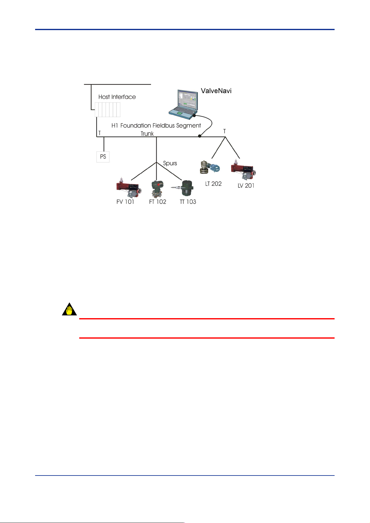
3.2 Reference Model Process
Throughout this manual we will use a simplified Fieldbus Reference Model Process. This is
an example of a simple process (It is not a practical process) that illustrates many elements
of Foundation fieldbus that are required in a successful installation.
3-2
Figure 3.1 ValveNavi Reference Model Fieldbus Segment
This User’s manual is intended to instruct the use of the ValveNavi software with a
Yo k ogawa YVP valve positioner. ValveNavi may be used offline but is normally connected
to a YVP positioner. Prior to using ValveNavi:
• The positioner must be correctly installed on a valve and connected to an air supply.
See the YVP110 User’s Manual(IM 21B04C01-01E).
• The PC running ValveNavi must have a National Instrument AT-FBUS, PCI-FBUS or
PCMCIA-FBUS interface card installed and configured in the Windows registry. Carefully follow the installation instructions provided with the interface card.
WARNING
Improper setup can interfere with process control.
• NI-FBUS communications manager software must be setup and running.
• The positioner must be assigned a fieldbus node address and a device tag. It is
recommended that this be performed while the device is connected as a single device
to a test segment, not while connected to an operating control segment. This will
require a different configuration of the interface card.
• The entire fieldbus segment must be configured, with all required function blocks softwired and scheduled.
Wiring practices for Foundation fieldbus differs significantly from 4 to 20 mA instrument
wiring. Please Refer to the Foundation Fieldbus Application Guide 31.25 kbits/s Wiring and
Installation, AG-140 Revision 1.0 or later. However, a few remarks regarding wiring of the
devices are included here. The positioner must be installed properly on a segment before
the ValveNavi software can be used.
IM 21B04C50-01E
Page 17

<Toc> <Ind> <3. INSTALLATION OF HARDWARE AND SOFTWARE>
3.2.1 Wiring requirements
Note that there are cable requirements that must be met for reliable installations. The cable
used must support the digital data signals without reflections, noise or attenuation. The
type A cable should be used whenever possible and especially for long transmission
distances or for segments with many branches (spurs).
● Power conditioner
Use a power conditioner for each segment. The conditioner must be foundation fieldbus
compliant. The power conditioner functions to isolate the digital signals from the power
source.
● Power supply
The YVP positioner complies with the foundation specification voltage requirements of 9 to
32 volts. The power supply must conform to these requirements with consideration for the
current drawn by all devices powered by the segment. The YVP maximum current
consumption is 17 mA.
● Terminator
Every fieldbus segment requires two (and only two) approved terminators. Terminators are
passive circuits that damp signal reflections in the circuit. For simple segments having
short runs and few spurs, the terminator location can be at each end of the longest cable.
For very short cables both terminators can even be located in the power conditioner.
3-3
IM 21B04C50-01E
Page 18

<Toc> <Ind> <3. INSTALLATION OF HARDWARE AND SOFTWARE>
3.3 Installing NI-FBUS
ValveNavi software interfaces to the fieldbus segment through an interface card that must
be installed in the PC running ValveNavi. The card is supplied with NI-FBUS installation
software. ValveNavi is designed to operate only with National Instruments NI-FBUS cards,
which are AT-FBUS, PCI-FBUS, or PCMCIA-FBUS.
Prior to using ValveNavi, install the NI-FBUS card and its software in accordance with the
instructions provided by National Instruments, Inc. Note that the instructions are different
for the AT card used in a desktop and the PCMCIA card normally used with a laptop.
Furthermore, the instructions are different for Windows 2000, for Windows XP, and
Windows Vista.
Note that there are two NI configuration tools that serve separate purposes:
• NI-FBUS Interface Configuration Utility- This is used to install and set up interface
boards. It provides access to IRQ and memory settings needed for Windows. It
provides tools for importing DD’s. It is described in the Getting Started manual
supplied with the NI-FBUS interface card.
• NI-FBUS Fieldbus Configuration System- This is the tool for configuring the
Foundation fieldbus network, including the devices, setting up the control strategy, and
schedule. It is described in the NI-FBUS Configurator User Manual installed in the
program online help. After opening the NI-FBUS Fieldbus Configuration System, click
Help>>Online Help to open the manual in PDF format.
3-4
WARNING
Do not configure the interface as a Link Master when connecting to the segment with an
existing host. Disruption of control may result.
3.3.1 Configure the NI-FBUS interface card safely for different tasks
The configuration of a portable PC for use with ValveNavi will vary depending on the
immediate task. If ValveNavi will be used to maintain or configure a valve on an existing
Foundation fieldbus segment, the PC running ValveNavi must configured carefully so it
does not interfere with control communication. Two configurations are described in the
following sections.
Tab le 3.1 Two configurations of the NI-FBUS Interface Card
To configure a positioner in the Foundation
fieldbus segment with a host computer.
To configure a positioner in the segment
without other host (Initial Setup, for example).
The NI-FBUS Interface card must be configured as a BASIC
DEVICE at a Visitor address.
The NI-FBUS Interface card must be configured as a LINK
MASTER DEVICE at a FIXED address (0⫻10 is
recommended).
T0301.EPS
NOTE
A Visitor device will not start until connected to a running segment with an active LAS that
can assign a node address to the visitor.
IM 21B04C50-01E
Page 19
<Toc> <Ind> <3. INSTALLATION OF HARDWARE AND SOFTWARE>
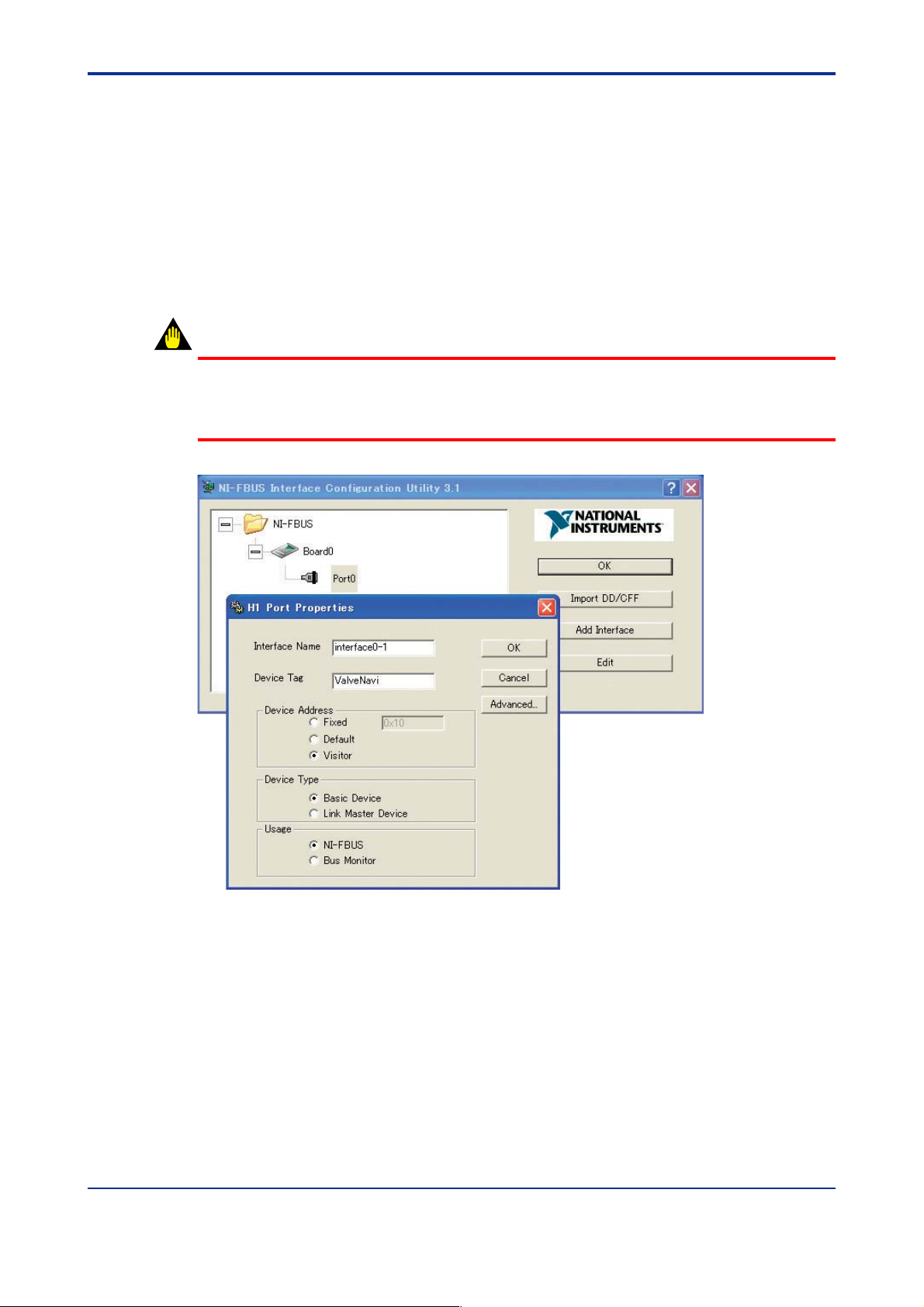
● Configuring the interface card to safely connect to the Foundation fieldbus
segment with a host computer
If the YVP positioner is connected on a segment that has a host computer, the interface
card and PC must be configured as a BASIC DEVICE at a Visitor address. Open the
configuration utility (NI-FBUS Interface Configuration Utility) and follow the instructions in
the NI manual.
Select Port and click Edit to bring up the Port dialog shown in Figure 3.2. Set the
parameters exactly as shown in the figure, and click OK. (The Device Tag can be set to any
name that will be meaningful when seen by a remote interface operating on the same
segment.)
WARNING
ValveNavi is the tool for setup and maintenance. Do not connect it to the operating process.
That may change the mode of YVP and cause unpredictable stop or events on the process.
Use it only when the process is OFFLINE.
3-5
Figure 3.2 NI-FBUS Interface configuration utility setting the card as a Basic Device
IM 21B04C50-01E
Page 20
<Toc> <Ind> <3. INSTALLATION OF HARDWARE AND SOFTWARE>
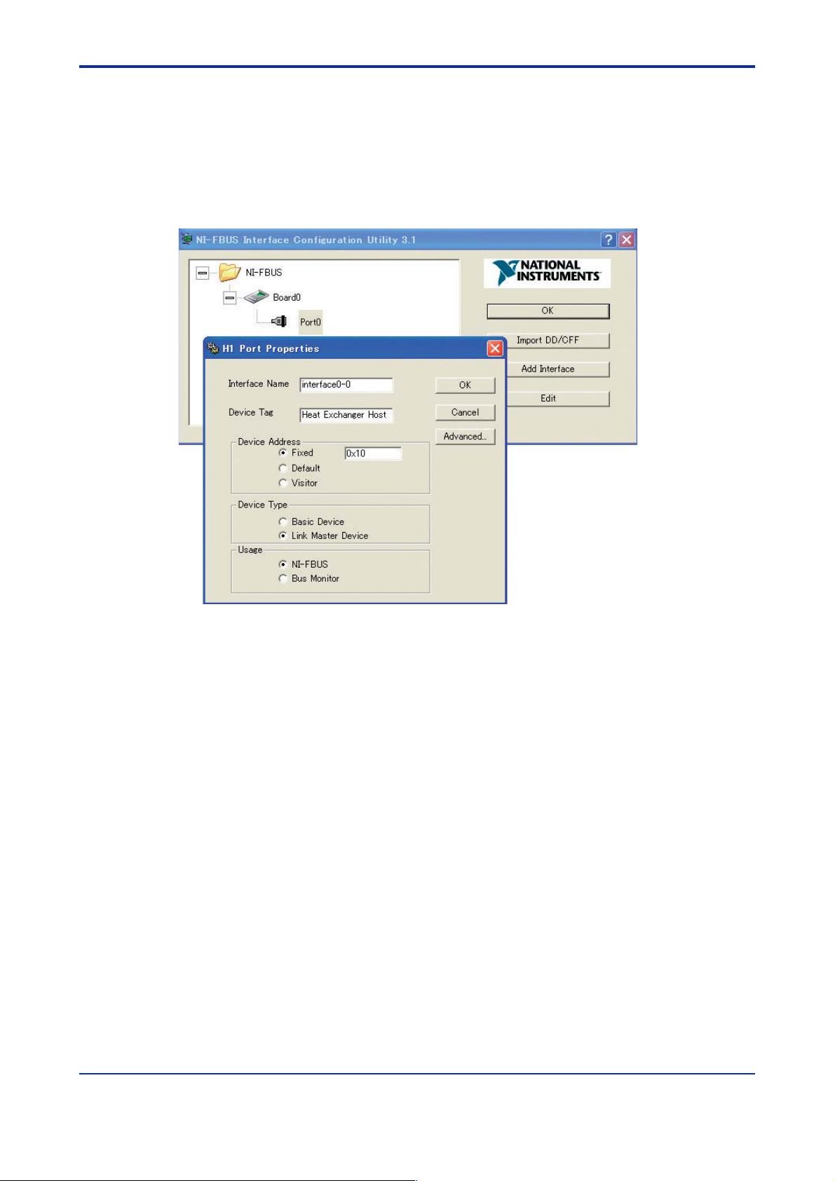
● Configure the interface card for one to one Communication
The visitor configuration described previously will not work if the only devices that are
connected to the segment are YVP positioner and the NI-FBUS interface card, because
there will be no link master to schedule messages. It is necessary, therefore, to configure
the interface card as a link master, exactly as shown in Figure 3.3. (The interface name and
Device Tag may be any convenient names. The names will not be seen by any other
interfaces and are not important.)
3-6
Figure 3.3 Configure the interface as Link Master
3.3.2 Installing the Device Descripfions (DD) with NI-FBUS Interface Configuration Utility
The NI-FBUS Interface Configuration Utility must be used to install the DD for the YVP, and
also to install the standard dictionary. If you do not have the DD file, you can download it
from our web site. Visit the following web site or contact our subsidiaries.
http://www.yokogawa.com/fld
Step 1 Click [Import DD/CFF] and in the new dialog click [Browse]. Select the
desired .ffo file or .cff file and click [Open]. In the import DD dialog click [OK]
Step 2 Repeat for each device that will communicate with ValveNavi.
IM 21B04C50-01E
Page 21

<Toc> <Ind> <3. INSTALLATION OF HARDWARE AND SOFTWARE>
3.3.3 Location of DD files and .DCT file
After the DDs have been successfully installed, they will appear in the installation
subdirectory of NI-FBUS. The form of the directory tree will be as shown in Table 3.2.
Tab le 3.2 NI-FBUS Installation Subdirectory Structure
NIFBUS (or other install directory name)
Data
594543 (YOKOGAWA's ID)
0001 (for YVP110 without software download function)
02nn.ffo*
02nn.sym
03nn.ffo
03nn.sym
04nn.ffo
04nn.sym
0007 (for YVP110 with software download function)
01nn.ffo*
01nn.sym
02nn.ffo
02nn.sym
03nn.ffo
03nn.sym
XXXX (Other device type)
T0302.EPS
3-7
Note: ‘nn’ stands for two-digit value. The number may be changed by revision up.
IM 21B04C50-01E
Page 22

<Toc> <Ind> <4. ValveNavi ADMINISTRATION>
4. ValveNavi ADMINISTRATION
In the previous chapter, we described the installation of the Foundation fieldbus
communications software and hardware. In this chapter, we will describe the
procedures for installing ValveNavi software.
The ValveNavi installation procedures outlined in this chapter assume a working
knowledge of Microsoft Windows, the Yokogawa YVP positioner, and of Foundation
fieldbus communications and function block technology. For further information
about the YVP positioner, see YVP110 User’s Manual (IM 21B04C01-01E).
4.1 Hardware and Software Requirements
ValveNavi runs on a standard IBM-compatible computer. To successfully install and run
ValveNavi, the computer system must meet minimum hardware and software requirements.
The following lists the minimum hardware and software requirements:
•Windows 2000 service pack 4, XP service pack 2, or Vista service pack 1 operating
system
•Pentium 166 MHz microprocessor or faster
4-1
• CD-ROM drive
• National Instruments NI-FBUS interface card and server software
• 500 MB of free hard disk space to install and run ValveNavi
4.2 Installing ValveNavi
ValveNavi is distributed on a CD-ROM for Windows 2000, Windows XP, or Windows Vista.
1. Insert the ValveNavi installation CD-ROM into the CD-ROM drive.
2. Click Start > Run, then type x:setup (x is the letter of the CD-ROM drive.)
3. Follow the prompts on your screen to complete the installation process.
ValveNavi Administration and ValveNavi Help are also installed along with ValveNavi. After
successful installation of ValveNavi software, the system administrator of ValveNavi should
change the default logon and password and set up user accounts through the ValveNavi
Administration program. Secure the ValveNavi CD-ROM in order to provide system
security. Anyone with access to the setup disk could reload the software and thereby get
access to YVP devices. For more details, see 4.6.
NOTE
In case of ValveNavi install folder (ex: C¥Program Files¥ValveNavi) is not writable, some
functions can not be used.
IM 21B04C50-01E
Page 23
<Toc> <Ind> <4. ValveNavi ADMINISTRATION>
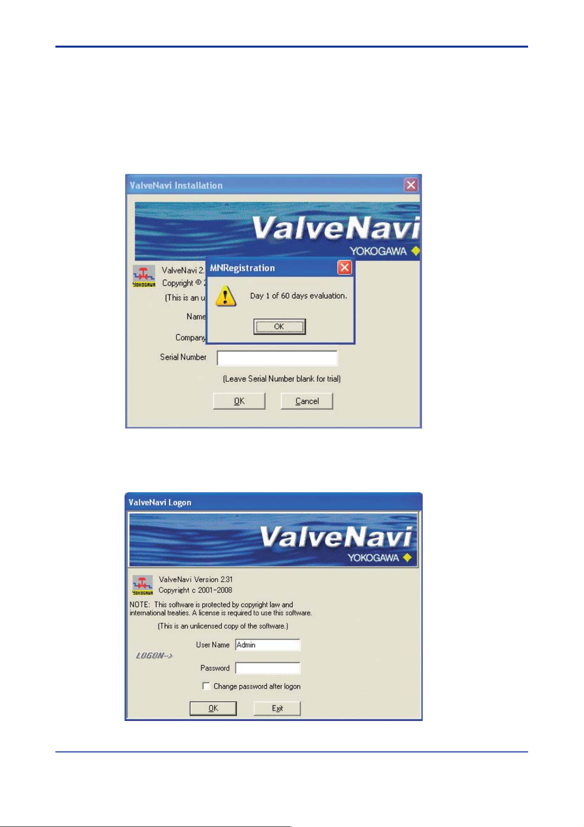
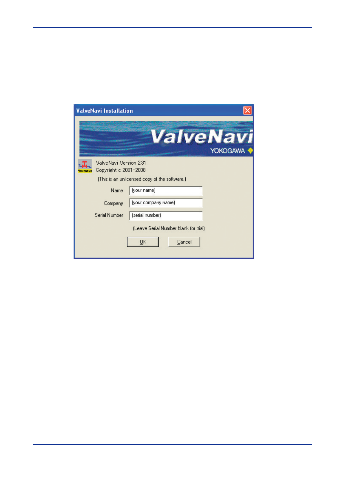
4.3 Trial Period
To start up ValveNavi, double-click the ValveNavi icon generated on the desktop.
This will open the Registration screen. Type your name and company name there.
ValveNavi can be used for 60 days without entering the serial number after installation on a
PC. If you are not a licensed user, leave the serial number box blank, then press OK. The
evaluation or trial period for the software is up to 60 days from the first day it is used, and
this time process will not be cleared even when uninstalling and reinstalling the software.
4-2
Figure 4.1 Dialog box showing trial limits
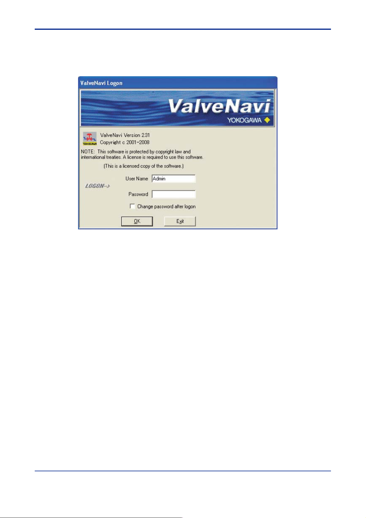
Click OK and logon in the ValveNavi Logon dialog (Figure 4.2). See page 4-6 for setting up
individual ValveNavi accounts and privileges.
Figure 4.2 Logon dialog
IM 21B04C50-01E
Page 24
<Toc> <Ind> <4. ValveNavi ADMINISTRATION>
4.4 Licensed User Process
Permanent use of this software requires a license for each computer on which it will be
used. If you purchased a licensed copy of ValveNavi, you will have received a CD-ROM
with a serial number. DO NOT LOSE THIS SERIAL NUMBER. KEEP IT IN A SECURE
LOCATION.
To start using ValveNavi as a licensed user, in the required information in the Installation
dialog (Figure 4.3), including the name of the person responsible for the registered
software, the company name and the software serial number, and press OK.
4-3
Figure 4.3 Installation Dialog
Once licensed with proper registration information, this registration dialog will no longer
open unless it is opened from the Help menu. Click Help/Installation Info to access the
Registration dialog.
IM 21B04C50-01E
Page 25
<Toc> <Ind> <4. ValveNavi ADMINISTRATION>
4.5 Logging on with Registration
Once you complete the registration of the software, you will enter from the logon screen as
shown in Figure 4.4.
4-4
Figure 4.4 Logon Screen
IM 21B04C50-01E
Page 26
<Toc> <Ind> <4. ValveNavi ADMINISTRATION>
4.6 Setting Up User Accounts
4.6.1 System Administration, Passwords, and Privilege Levels
In a plant with many users with various levels of training and responsibility, it is often
desirable to restrict certain users access to a limited range of functions. Starting the
ValveNavi program requires a valid account with a user name and a password for each
user. The privilege level associated with a ValveNavi account determines which functions
of the program the user is allowed to access.
The ValveNavi Administration program allows the administrator to perform all user account
administrative functions to run ValveNavi and to control access to the functionality of the
YVP positioner.
These administrative functions include:
• Adding new user accounts
• Deleting existing user accounts
• Changing existing user accounts
• Adjusting privilege levels
4-5
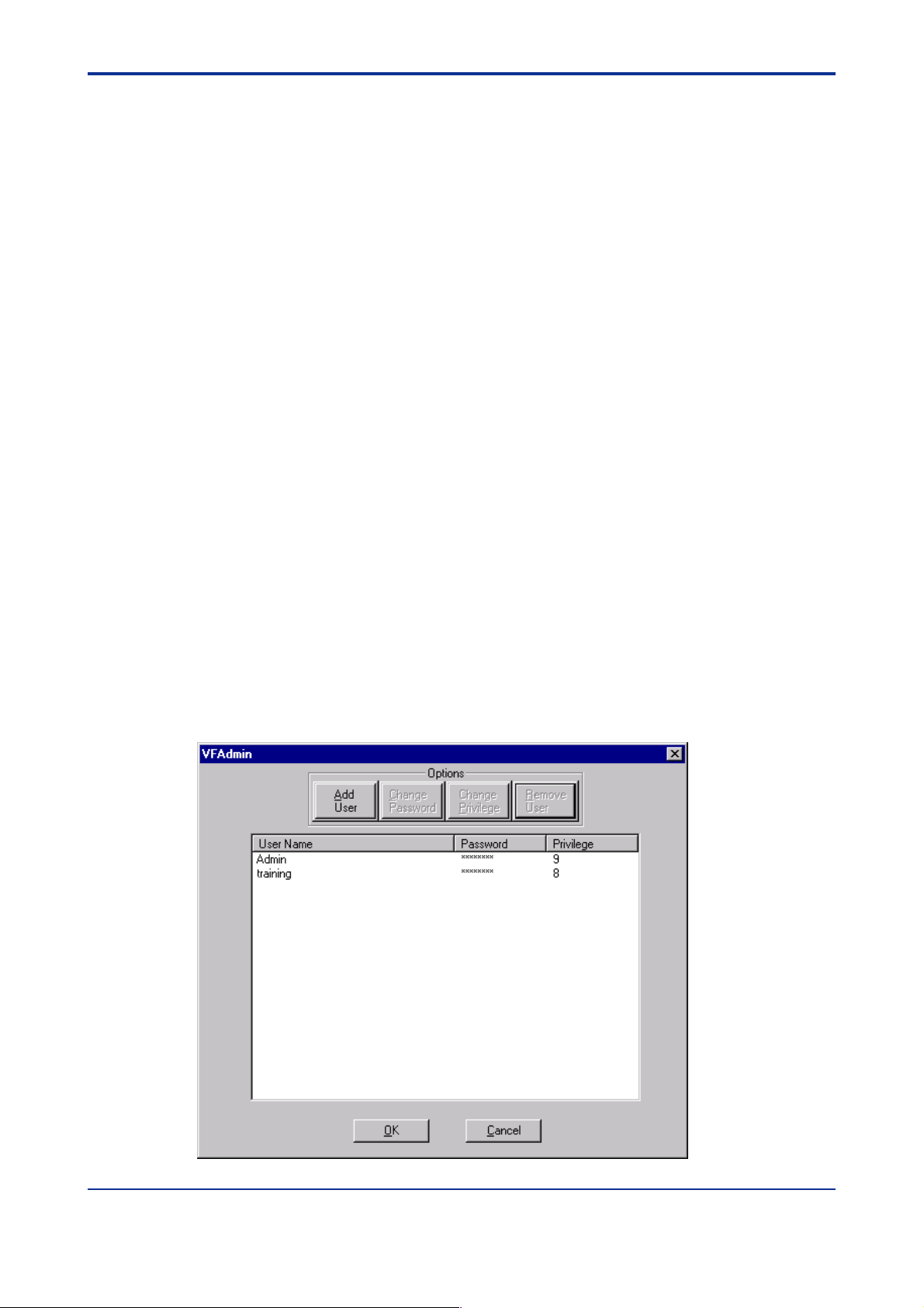
4.6.2 Start the Administration Program
After installation of ValveNavi, the ValveNavi administrator should change the default
passwords, set up the initial user accounts through the Admin program, and secure the
setup disk. Anyone with access to the setup disk could reload the software and thereby get
access to YVP devices.
To start ValveNavi Admininistration, select Start->Program->ValveNavi->ValveNavi
Admininistration. The administrative program prompts you for a logon name and password.
Log in for the first time with an administrator account. Enter the default logon name
(“Admin”) and leave password blank. (Note: The system is case sensitive, and you must
type the default names in correct case.) Then, clicking OK to open the VFAdmin dialog
(Figure 4.5).
Figure 4.5 Add Users in VFAdmin dialog
IM 21B04C50-01E
Page 27

<Toc> <Ind> <4. ValveNavi ADMINISTRATION>
The program already contains two accounts.
• The first account is the administrator account, which you are using, with the logon
name “Admin” (note that this is case sensitive with a capital A) and the initial password
is blank (no password). Immediately use the administration program to install a
password for administration to make the system secure from unauthorized use.
• The second account enables use of the YVP process controller simulator with the
logon name of “training” (lower case) and password of “training” (lower case). The
process control simulator will simulate, in software, a process with a dead time of one
second and a lag of five seconds. The process controller simulator is useful for
training users on the many functions and features of the YVP positioner and its PID
function block.
WARNING
Do not logon with a “training” account to use ValveNavi with a valve that is not isolated from
the operating process. Control links will be destroyed by using the simulate function.
CAUTION
4-6
It is important that the administrator change the default logon names and passwords for the
administrator account and the training account. Continued use of the default logon account
names and passwords makes the system less secure.
4.6.3 Privilege Levels
Each user is assigned an account. For each account, there is an associated privilege level.
Privilege levels range from 0 to 9, with level 0 the lowest and 9 the highest. The following
defines several privilege levels, which control access to specific functions of the ValveNavi
program. Services which are not accessible to a particular level are “grayed” out.
Level 0
Allows the user to logon to ValveNavi only if the connected YVP is in Auto. The user can
send commands that will reply with configuration, calibration, and status information, but
the user cannot change any information. Level 0 users cannot go to Out Of Service or
Manual.
Level 1
Allows the user access Auto, Manual or Out Of Service states. The user can transfer from
one mode or state to another (i.e. the user can take the YVP out of Auto and put it in
Manual). The user can then set valve position. However, the user cannot change the
calibration or configuration. The level 1 user cannot access the PID dialog.
Level 2
This level is not defined.
Level 3
Allows the user to change the configuration or calibration values, but does not allow the
user to perform calibration and tuning operations that stroke the valve (Find Stops,
Autotune or diagnostics).
The user may open the PID dialog and use it to change PID modes and to move the valve
in manual or change process variable setpoint. The user can enter tuning parameters for
the process variable PID control.
IM 21B04C50-01E
Page 28

<Toc> <Ind> <4. ValveNavi ADMINISTRATION>
Level 4
Allows the user to perform all operations except Download Configuration to YVP.
Level 5
This level is not defined.
Level 6
This level is not defined.
Level 7
This level is not defined.
Level 8
This level is intended for training and should be used cautiously. It grants all of the
privileges of level 4 plus allows access to the Simulation State of the process controller.
(The simulation of the PID Block allows the user to run the process controller without
connecting a process variable input to the YVP and is useful for learning how to operate the
process controller).
WARNING
4-7
The simulation state must not be used if the valve is connected in a control loop or the if the
valve is controlling process flow.
The simulation state will permanently remove important control loop configuration
information from the YVP valve positioner. The soft-wired connection between the PID
functions block and its input function block must be restored after simulation is used.
Reconfigure function block links after using simulate. The Clear Device command must be
used when downloading restored configuration.
Level 9
Allows access to all YVP functions. In addition, it is the only level allowed to logon to the
administration program.
The administrator has an account of privilege level 9. There must be at least one user of
privilege level 9 in order to get access to the administration program.
IM 21B04C50-01E
Page 29
<Toc> <Ind> <4. ValveNavi ADMINISTRATION>
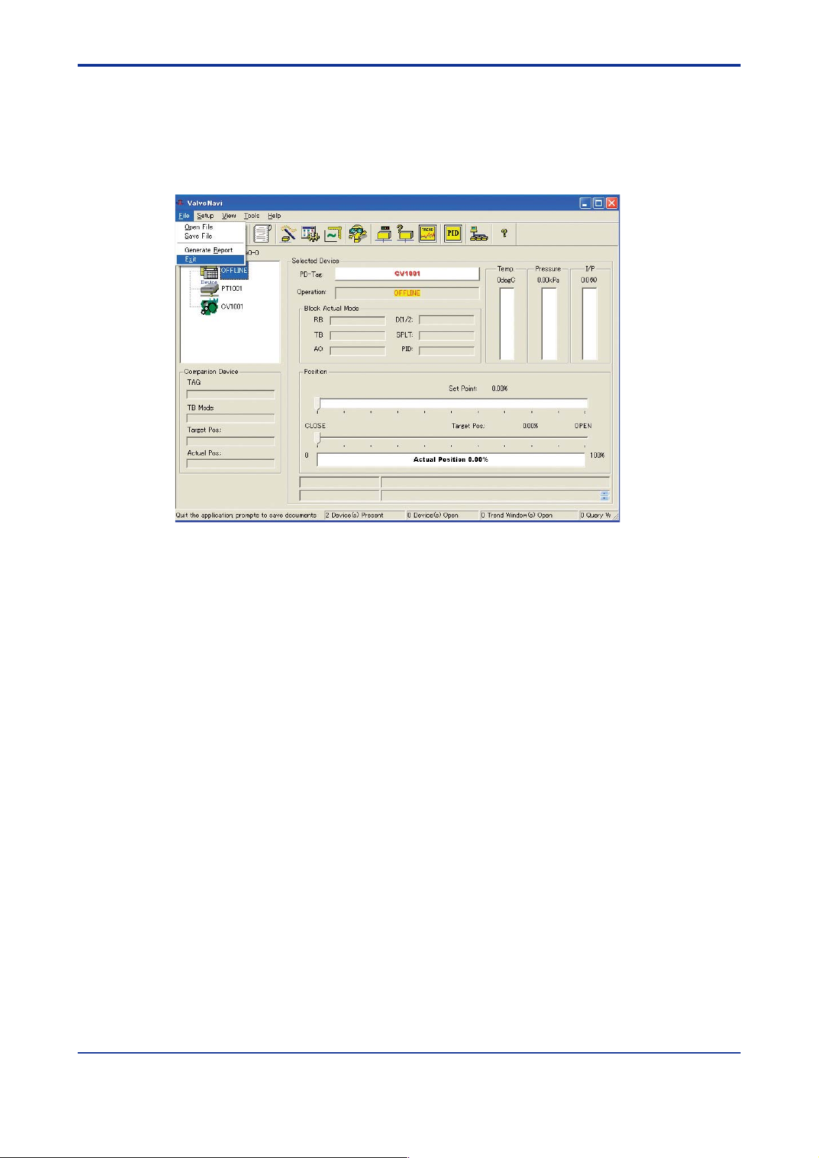
4.7 Finish ValveNavi
To finish ValveNavi, select Exit from File Menu. Clicking Yes to the Confirmation message
will finish ValveNavi.
4-8
Figure 4.6 To Finish ValveNavi
IM 21B04C50-01E
Page 30
<Toc> <Ind> <5. FOUNDATION FIELDBUS OVERVIEW>
5. FOUNDATION FIELDBUS OVERVIEW
This chapter will introduce concepts that are used in most parts of the manual. It will
briefly introduce Foundation Fieldbus blocks, and some of the essential block
concepts. Throughout the manual we will reference a simple process example. The
example is a simple heat exchanger with two control valves, and three measurement
devices. The controls are configured in a cascade arrangement to illustrate
concepts of transfer between modes and states of the various levels of control.
5.1 Reference Model Process Used in This User’s Manual
The heat exchanger model is shown in Figure 5.1. It is not a practical process, but
incorporates elements that illustrate important features of ValveNavi. Note that each of the
devices has a device tag that will be used to identify devices in ValveNavi. The process
consists of a vessel with a product vapor inflow, which is condensed, and flows out as a
liquid outflow. The tank level is controlled by an outflow control valve, LV 201. The tank
contents are chilled by coolant water. The temperature is controlled by a temperature
controller cascaded to a flow controller. The coolant flow is controlled by control valve FV
101.
5-1
Figure 5.1 Heat exchanger
IM 21B04C50-01E
Page 31

<Toc> <Ind> <5. FOUNDATION FIELDBUS OVERVIEW>
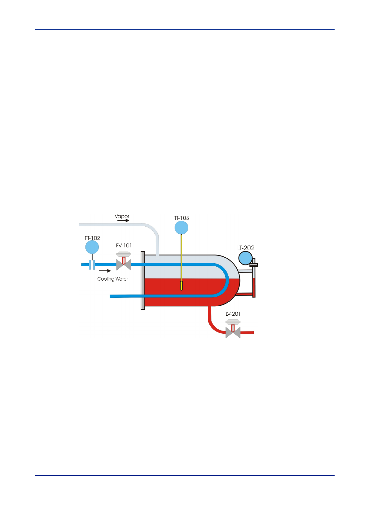
5.1.1 P & I D
Figure 5.2 Piping and Instrumentation Diagram
5-2
The piping and instrument diagram (Figure 5.2) shows, in schematic form, the physical
devices and indicates the measurement and control functions that reside in each device.
The coolant flow transmitter, FT 102, has only a transmitter function, but the coolant flow
control valve, FV 101, has a PID control, two limit switches (DI blocks) and an AO block
all located in the YVP valve positioner. The flow of control information between devices
is indicated by dashed lines. The DI blocks, ZSL 101 and ZSH 101, serve as low and
high stem position limit switches, respectively.
Liquid level is controlled by a remote controller LC201 (to demonstrate Remote
Cascade operation). The controller receives the process measurement from level
transmitter LT 202. The PID control regulates the valve LV201 (an YVP positioner with
an Analog Output Block, and 2 DI function blocks. The DI blocks, ZSL 201 and ZSH
201, serve as low and high stem position limit switches, respectively.
IM 21B04C50-01E
Page 32

<Toc> <Ind> <5. FOUNDATION FIELDBUS OVERVIEW>
5.1.2 Function block links
Each of the control functions is represented in the Control configuration as Foundation
fieldbus Function Blocks. All the blocks in the temperature cascade are shown in Figure
5.3. They are grouped according to the physical device containing them, and they are
shown with the links between the blocks (“soft wiring” connections) for data flow.
Similarly, the level loop function blocks are shown in Figure 5.4.
5-3
Figure 5.3 Temperature Cascade Block Diagram
Figure 5.4 Level loop block diagram
IM 21B04C50-01E
Page 33

<Toc> <Ind> <5. FOUNDATION FIELDBUS OVERVIEW>
Finally, to complete the model, ValveNavi is shown, in Figure 5.5, temporarily connected
to the heat exchanger’s Foundation fieldbus wiring at an intermediate point. The Heat
Exchanger Reference Model segment consists of a Heat Exchanger Host in a control
center with a Foundation fieldbus trunk running to two junction boxes. One junction box
has spurs to the flow and temperature control devices and the other connects to the
devices controlling tank level. A power supply with isolation electronics and two
terminators are also shown. The interface cards (NI-FBUS ) used with the ValveNavi
computer must be configured so that it will not interfere with the Heat Exchanger Host.
5-4
Figure 5.5 ValveNavi connected as a visitor device
WARNING
Do not connect a ValveNavi PC to an operating segment.
WARNING
Do not cause a short circuit in a working segment while connecting any device.
IM 21B04C50-01E
Page 34

<Toc> <Ind> <5. FOUNDATION FIELDBUS OVERVIEW>
5.2 Device Operational States and Block Modes
5-5
Figure 5.6 Device Operation State in Pop-up Menu
The Operation State can be accessed several ways. From the Device Selection frame,
right click the desired device to pop up a menu list and select Device Operation State. In
the tool bar click the Device Operation State icon. Or choose Tools>Device operation State
from the Menu bar.
The Device operation State dialog will then appear offering choice of Out Of Service,
Manual and Normal states.
Figure 5.7 Device Operation State Dialog
IM 21B04C50-01E
Page 35

<Toc> <Ind> <5. FOUNDATION FIELDBUS OVERVIEW>
ValveNavi manages the operational states of the positioner and its embedded PID controller by controlling the target modes for each of the function blocks. The actual mode of each
block may be different from the target mode. The actual mode is controlled by the block
itself in accordance with mode rules based on the quality of the data and modes of the
linked blocks. A brief summary of modes follows, but a thorough discussion of modes is
beyond the scope of this instruction. The interested reader is referred to the Fieldbus
Foundation that specifies the formal rules for mode changing.
Three operational states are set by ValveNavi (Figure 5.6 and Figure 5.7). The Out Of
Service (OOS) state forces all of the blocks to Out Of Service Mode. The outputs remain at
the values prior to the state change. All output calculation is suspended. Back calculation
values are passed to other linked blocks to enable initialization. Note that the PID will
remain in OOS after configuration changes unless it is put into one of its allowed modes
from the PID dialog. The PID dialog can be started from the Device Operation Dialog.
Tab le 5.1 Allowed Block Modes For Three Operational States
5-6
Operational state
Out of Service (OOS)
Manual operating
state
Normal Operating
state
Note: Italics indicate a permitted actual mode but a dis-allowed target mode.
Bold type indicates a target mode.
PID
OOS
IMan
Man
Auto
CAS
RCAS
OOS
Iman
RCas
IMan
Man
Auto
Cas
Function Block and Block Modes
AO
1 or more block is in OOS
OOS
Man
Auto
CAS
RCas
Man Auto Auto
Each block must be one of the modes below
Auto
Cas
RCas
TB(Auto)
OOS
Auto
Auto Auto
RB(Auto)
OOS
Auto
T0501.EPS
IM 21B04C50-01E
Page 36

<Toc> <Ind> <5. FOUNDATION FIELDBUS OVERVIEW>
5.3 Block Modes
All blocks (function/transducer/resource) have operating modes. There are eight modes
defined in the Foundation fieldbus specification. Not all modes are supported by every
block. For example, the Discrete Input (DI) block supports just Auto, Man, and OOS. The
action of the modes are described in the following paragraphs. Transfers between modes
are managed by the function blocks in response to manual commands, in response to
changes in the modes of linked blocks, and in response to changes in the quality of the
parameters that are transmitted. Control and status options can be set to manage mode
changing behavior.
(1) Remote-Output (Rout)
The block output is being set by a Control Application running on an interface Device
through the remote-output-in parameter. The algorithm is bypassed and the remote block
controls its output directly. The algorithm must initialize so no bump is experienced when
the mode switches to auto. A remote-output-out parameter is maintained by the block to
support initialization of the control application when the block mode is not remote-output.
The setpoint may be maintained or, optionally, be initialized to the process variable value.
(2) Remote-Cascade (RCas)
The block setpoint is being set by a Control Application running on an interface device
through the remote-cascade in parameter. Based on this setpoint, the normal block
algorithm determines the primary output value. A remote-cascade out parameter is
maintained by the block to support initialization of the control application when the block
mode is not remote-cascade.
5-7
(3) Cascade (Cas)
A setpoint value supplied by another function block through the Cascade input parameter is
used by the normal block algorithm in determining the primary output value. This
connection between function blocks is defined by a link object.
(4) Automatic (Auto)
A local setpoint value is used by the normal block algorithm in determining the primary
output value. The local setpoint value may be written by an operator through an interface
device.
(5) Manual (Man)
The block output is not being calculated, although it may be limited. It is directly set by the
operator through an interface device. The algorithm must initialize so no bump is
experienced when the mode switches. The setpoint may be maintained or, optionally, be
initialized to the process variable parameter value or to the setpoint value associated with
the previous (retained) target mode.
(6) Local Override (LO)
Applies to control and output blocks that support a track input parameter. In the local
override mode, the block output is being set to track the value of the track input parameter.
The algorithm must initialize so no bump is experienced when the mode switches from LO
back to the target mode. The setpoint may be maintained or, optionally, be initialized to the
process variable parameter value.
(7) Initialization Manual (IMan)
The block output is being set in response to the back-calculation input parameter status.
When the status indicates there is no path to the final output element, then the control
blocks must initialize to provide for bumpless transfer when the condition clears. A backcalculation out parameter is supported by all output and control class function blocks. The
setpoint may be maintained or, optionally, initialized to the process variable parameter
value.
IM 21B04C50-01E
Page 37

<Toc> <Ind> <5. FOUNDATION FIELDBUS OVERVIEW>
(8) Out of Service (OOS)
The block is not being evaluated. The output and setpoint are maintained at last value.
(9) Multiple Modes and States
The AO block must go to CAS mode to connect to a PID function block in cascade. To stop
the setpoint signal from the AO to the transducer block, the AO block must go into OOS
mode.
The following, Table 5.2, shows examples of mode operation (not showing all cases).
Tab le 5.2 Mode operation
5-8
Operation
Configure the transducer block
(Auto tuning, travel calibration,
diagnostics, etc.)
Configure transducer block
(Changing position control
parameters, etc.)
Manual valve positioning
from ValveNavi or other
human interface.
Manual valve positioning
from a PID controller human
interface
PID single loop control
PID cascade loop control
(AI) AO TB
Auto
Auto
PID
Manual
Auto
primary :Auto
secondary :CAS
OOS
Man
CAS
Cas
Cas
OOS
OOS
Auto
Auto
Auto
Auto
T0502.EPS
When a block is in OOS mode, its output status will be “bad,” so that any connected blocks
will know and automatically change their modes. For example, when a PID block sees bad
status in its BKCAL IN, it will go to IMAN mode for initialization to the downstream block
while awaiting the status to return to “good cascade. ”
IM 21B04C50-01E
Page 38

<Toc> <Ind> <5. FOUNDATION FIELDBUS OVERVIEW>
5.4 Examples of IVI Operational States
Examples of operational states that are combinations of block modes are shown in the
following figures.
A new device or a newly configured device may start up in the out of service (OOS) state
shown in Figure 5.8.
5-9
Figure 5.8 Out of service at startup
To transfer to the manual state which allows ValveNavi to adjust the valve position, click the
Operating State icon and select Manual. Enter a setpoint in the Set Point text box (Figure
5.9) then click OK, or drag the Set Point slider to the desire value. If the positioner is
configured with a non-linear (such as =%) characteristic, the Target Position will be
computed from the setpoint but may differ in value. The configuration options of Tight
Shutoff Below, Full Open Above, as well as high and low position limits will be applied to the
Set Point to arrive at the correct Target Position.
Figure 5.9 Manual State
IM 21B04C50-01E
Page 39

<Toc> <Ind> <5. FOUNDATION FIELDBUS OVERVIEW>
When the positioner has been placed in normal, it waits for the PID block to begin to send it
a setpoint. It will remain in auto mode at the current valve position. When this condition
exists, it is necessary to place the PID block in its normal mode.
5-10
Figure 5.10 Normal State Waiting For internal Controller block
When the process control PID is located within the positioner and when the PID receives its
setpoint from a Foundation fieldbus function block, the normal state will be as shown in
Figure 5.11. Both the PID and AO blocks are in Cas mode.
Figure 5.11 IVI Showing Cascade Normal State
IM 21B04C50-01E
Page 40

<Toc> <Ind> <5. FOUNDATION FIELDBUS OVERVIEW>
When the positioner is receiving its position setpoint from a remote computer system such
as a DCS then the normal state for the positioner will be as shown in Figure 5.12. In this
example the level control valve LV201 is receiving its signal from a DCS. The AO block is
shown in RCas mode.
Figure 5.12 Remote Cascade Normal State
5-11
If an internal PID is used in a cascade where the PID receives a setpoint from a remote
computer system, then the normal state will have the PID in RCas mode and the AO will be
in Cas mode (not shown).
IM 21B04C50-01E
Page 41

<Toc> <Ind> <5. FOUNDATION FIELDBUS OVERVIEW>
5.5 Changing Operational States
The Foundation fieldbus Application process specifies the mode handling for interoperable
function blocks. It also specifies which mode a block must be in when each parameter is
written. ValveNavi provides an intelligent, optimized process for managing configuration
and calibration changes. For efficiency, it does not place blocks into Out Of Service mode
unless the parameter requires OOS. It analyzes the requested changes and then sets the
correct mode for each affected function block. The actual block modes are displayed in the
IVI.
The Foundation fieldbus specifies a mechanism for transferring between function block
modes. The user declares a target for the block mode, but the actual mode is set by the
block in accordance with rules. The rules allow modes based on the quality of input data
and quality of the connection to the process. YVP function blocks comply with the FF rules.
ValveNavi sets target modes for individual function blocks as required by configuration,
calibration, diagnostics and other services. It sets target modes for group of function blocks
to achieve three operational states of the positioner: Out of Service, Manual, and Normal.
(1) Changing Target Operational State
When a configuration or other process requires any of the affected function blocks to go
into OOS mode, ValveNavi opens a Warning dialog as shown in Figure 5.13
5-12
Figure 5.13 Out Of Service State Change Warning
(2) Changing to Auto from OOS
In OOS, the YVP can be switched to Auto in order to return the device to the previous Auto
state by clicking on Auto. In the event the user has selected “bumpless transfer” the device
will execute the bumpless transfer routine.
IM 21B04C50-01E
Page 42

<Toc> <Ind> <6. QUICK TOUR OF ValveNavi>
6. QUICK TOUR OF ValveNavi
In the quick tour we will briefly introduce each of the tools provided by ValveNavi.
The chapters that describe the tools in details follow the quick tour.
6.1 Introduction
ValveNavi uses an integrated valve interface, IVI, to display all valve and positioner
variables and to provide access to services, such as configuration and calibration tools.
The information and controls for services are arranged in frames within IVI. From the IVI
the user has single click access to the PID Controller interface. IVI displays and updates
real time values for valve position, valve setpoint and actuator pressure numerically and
graphically.
Data objects are grouped in “frames” within the IVI display as described below.
6-1
Figure 6.1 Integrated Valve Interface (IVI)
IM 21B04C50-01E
Page 43

<Toc> <Ind> <6. QUICK TOUR OF ValveNavi>
6.2 Fieldbus Device Tree
All of the devices on the bus segment live list are shown as icons in the Device Selection box.
Figure 6.2 Device Tree
Click on the YVP device to open a communications session with the positioner. The
fieldbus segment live list is continuously scanned and devices are shown when present.
Devices that have communications failure are shown with a red X. The selected device is
shown with a red check-mark.
6-2
When a device is selected, a warning dialog informs that an attempt is made to connect to
a new device. Then the Read configuration dialog displays progress uploading device data.
IM 21B04C50-01E
Page 44

<Toc> <Ind> <6. QUICK TOUR OF ValveNavi>
6.3 Menu Bar and Tool Bar
The IVI offers tools and wizards using standard Windows conventions, offering multiple
paths to functions to suit a user’s preferences. Use the menu bar, the tool bar icons, or
popup menus in the Device Selection frame. When the cursor is moved over an icon a Tool
Tip appears to identify the icon’s purpose.
6.3.1 Menu items
Pull down menus are listed below and shown in Figure 6.3.
Figure 6.3 Menu and tool bars
• File
• Setup
•View
•Tools
6-3
• Help
Help use Web Browser technology to provide flexible access to help for all ValveNavi
windows. It is good practice to open help.
6.3.2 Toolbar icons
Toolbar services are listed in Table 6.1. An icon may be “grayed out” to indicate that its
function is disabled.
Tab le 6.1 Toolbar Icons
Open configuration file
Save Configuration file
Download configuration
Generate a report file
Diagnostics
Change device operation
state
Query device
View Trend
Setup Wizard
Configuration management
Calibration management
PID Process controller
Rescan the field bus
segment
About ValveNavi version
T6.1.EPS
IM 21B04C50-01E
Page 45

<Toc> <Ind> <6. QUICK TOUR OF ValveNavi>
6.4 Control Valve Faceplate
The control valve faceplate frame encloses displays and controls for working with the
positioner.
6-4
Figure 6.4 IVI Positioner Faceplate Frame
Figure 6.4 shows an example of the control valve faceplate frame in the IVI. The
positioner’s tag is shown in the PD-Tag field. The current operating state of the positioner is
shown in the Operation control button displaying, in this example, “NORMAL STATE.”
Individual block modes are displayed for each of the positioners internal function blocks.
The valve position Set Point is displayed by the graphical position of a slider control and
numerically to two decimal places. Below the setpoint display, the target position and actual
position are shown as a slider and bar respectively, with values shown to two decimal
places.
The Target Position is derived from the Set Point signal based on the parameters defined in
Configuration Services, on the valve characterization and on the configuration of air-toopen or air-to-close. It is further modified by any limits that may be configured.
IM 21B04C50-01E
Page 46

<Toc> <Ind> <6. QUICK TOUR OF ValveNavi>
6.5 Companion Device Display Frame
This Companion Device frame displays and updates real time values for transducer block
mode, target position, and valve position. It is used to observe summary information from a
second positioner connected in the same segment as the selected device.
Figure 6.5 IVI Companion Device Frame
6-5
6.6 Status Frame
Below the position bar display, the Status Frame displays Analog Output (AO) block and
PID block Scheduling status. In addition, the transducer block error (XD ERROR) is
displayed. The communication error text box accumulates error messages that can be
copied to a text file for analysis.
To clear the error text box, click View>Clear Comm Error Display.
Figure 6.6 Status frame
IM 21B04C50-01E
Page 47

<Toc> <Ind> <6. QUICK TOUR OF ValveNavi>
6.7 Accessing Services in ValveNavi
Services in ValveNavi are accessed by three methods that are standard Windows techniques.
• By the Tools menu, after a device has been selected and opened, or
6-6
• By the toolbar icon, after a device has been selected and opened, or
•From the Device tree with a popup menu, by right clicking on the desired device.
IM 21B04C50-01E
Page 48

<Toc> <Ind> <6. QUICK TOUR OF ValveNavi>
6.8 Setup Wizard
This setup wizard provides, in a single tool, all the services for setting up a basic positioner.
It includes a sequence for basic configuration and basic tuning. It is most useful for first time
setup of the positioner. Follow the step-by-step instructions to quickly complete the basic
setup and start running the valve.
6-7
Figure 6.7 Setup wizard
IM 21B04C50-01E
Page 49

<Toc> <Ind> <6. QUICK TOUR OF ValveNavi>
6.8.1 Actuator Wizard
This is the setup page in the setup wizard to configure the valve actuator information
contained in Transducer (TB) block. For a description of the parameters, refer to Actuator in
the Configuration window.
6-8
Figure 6.8 Actuator Wizard
IM 21B04C50-01E
Page 50

<Toc> <Ind> <6. QUICK TOUR OF ValveNavi>
6.8.2 Tuning Wizard
This tuning step in wizard allows the user to execute the combination of Search Stops and
Auto Tune described in Tuning in Calibration.
WARNING
Tuning will stroke the valve over its entire travel. Isolate the valve from the process prior to
the calibration.
6-9
Figure 6.9 Tuning Wizard
IM 21B04C50-01E
Page 51

<Toc> <Ind> <6. QUICK TOUR OF ValveNavi>
6.8.3 Travel Calibration Wizard
This travel calibration page in the setup wizard allows the user to calibrate the 0%, 50%, or
100% position points, when necessary. For a description of all the parameters and controls,
refer to Travel calibration.
6-10
Figure 6.10 Travel Calibration Wizard
IM 21B04C50-01E
Page 52

<Toc> <Ind> <6. QUICK TOUR OF ValveNavi>
6.8.4 Position Control Limits - Wizard
This position control limits page in the setup wizard allows the user to change the position
limit setting for the valve position configuration parameters in TB block. For a description of
all the parameters, refer to Position in Configuration window.
6-11
Figure 6.11 Position Control Limits Wizard
IM 21B04C50-01E
Page 53

<Toc> <Ind> <6. QUICK TOUR OF ValveNavi>
6.8.5 Finish - Setup Wizard
This is the final screen of the Setup Wizard that indicates that the basic setup is valid and
that provides a choice of Device Operation State before completing this setup. The Wizard
is not completed until the Finish button is pressed.
6-12
Figure 6.12 Setup Wizard Finished
IM 21B04C50-01E
Page 54

<Toc> <Ind> <6. QUICK TOUR OF ValveNavi>
6.9 Configuration Services
This page of the general configuration of the device includes Device Info, Block Tag Info,
and device installation options.
Figure 6.13 Configuration - General
6-13
IM 21B04C50-01E
Page 55

<Toc> <Ind> <6. QUICK TOUR OF ValveNavi>
6.10 Calibration Services
The calibration page has a tab for adjusting the positioner to the actual stroke (range) of the
valve, and for autotuning the position control algorithm. It also has a travel calibration
service that provides for making further adjustments to the valve stroke. The advanced tab
provides access to non-linear factors used to optimize dynamic performance.
6-14
Figure 6.14 Calibration with Range, Tuning, Travel, and Advanced Tabs
IM 21B04C50-01E
Page 56

<Toc> <Ind> <6. QUICK TOUR OF ValveNavi>
6.11 Diagnostic Services
The diagnostic page provides controls to perform the actuator and positioner signature test
procedures. It also displays the continuous diagnostic data that is an accumulation of valve
service.
6-15
Figure 6.15 General Tab of Diagnostics
IM 21B04C50-01E
Page 57

<Toc> <Ind> <6. QUICK TOUR OF ValveNavi>
6.12 Operation State
The Operation State Dialog controls switching between the block modes. Three types of the
state of operation are offered, and modes of each function block are set according to the
selected state.
6-16
Figure 6.16 Operation State
IM 21B04C50-01E
Page 58

<Toc> <Ind> <6. QUICK TOUR OF ValveNavi>
6.13 Device Query
The General page in Query Device provides access to device data in predefined categories. Simply select the category name from the drop down list box, then press Read to get
all the parameter values in the category. For each device, there is a query window available
and it is possible to open multiple query windows for multiple positioner devices at the
same time. The query window can be run while accessing other windows.
6-17
Figure 6.17 Query Device
The two tabs in the Device Query offer quick access to read parameters stored in the YVP.
The general tab accesses general data while the Block Parameters present all parameters
in each function plock.
IM 21B04C50-01E
Page 59

<Toc> <Ind> <6. QUICK TOUR OF ValveNavi>
6.14 PID Control Dialog
The PID Process Controller dialog contains the tools for managing the PID function block.
It is composed of frames that group controls and displays. The PID State frame displays
and controls the PID states (block modes), the setpoint and process variable, and the
Device tagname. In Manual State (M), drag the PID output slider to move the valve. In
Local State (L), drag the Setpoint Slider (or enter a value in the Setpoint text box) to change
the process variable setpoint. In Cascade (C), and in Remote cascade (R), the setpoint is
controlled by a function block or remote application.
6-18
Figure 6.18 PID Process Controller Dialog
Figure 6.19 Change Tuning Parameters Dialog
IM 21B04C50-01E
Page 60

<Toc> <Ind> <6. QUICK TOUR OF ValveNavi>
6.15 Rescan
Clicking Rescan button or selecting Tools >Re-scan Devices will refresh connections to all
working devices on the fieldbus segment. It will close the opened device you will lose
control until you have reselected a device. You will be prompted to confirm that a rescan is
acceptable.
Figure 6.20 Rescan Dialog
6.16 About
Clicking the About icon or selecting Help>About ValveNavi will display the version of
ValveNavi and the copyright notice.
6-19
Figure 6.21 About ValveNavi
IM 21B04C50-01E
Page 61

<Toc> <Ind> <6. QUICK TOUR OF ValveNavi>
6.17 Online Help
ValveNavi uses Web based technology for its online help. Click on Help>Help Topics to
start your normal browser (Internet Explorer or Netscape navigator).
6-20
Figure 6.22 Online Help
IM 21B04C50-01E
Page 62

<Toc> <Ind> <7. INTEGRATED VALVE INTERFACE (IVI)>
7. INTEGRATED VALVE INTERFACE (IVI)
The main application screen of ValveNavi is the Integrated Valve Interface (IVI) that is
displayed after a successful logon (ValveNavi Logon). It monitors the operation state
and status of the valve. It provides access to all other services.
7-1
Figure 7.1 IVI
ValveNavi operation begins with the Integrated Valve Interface, IVI. The IVI is a window
with a menu bar, a toolbar, a status bar, and frames containing displays and controls for
fieldbus data objects. Each of the data objects relates to Foundation fieldbus parameters.
The menu and tool bars provide access to services to work with files, devices and blocks.
The status bar shows status of the fieldbus segment. The frames are used to group the
device list tree, positioner data, Analog Output (AO) Block, and PID scheduling status, and
block modes, as well as device tag.
IVI displays all valve and positioner variables and provides access to services such as
Setup Wizard, Configuration, Calibration, and Diagnostics tools. The information and
controls for services are logically arranged in frames within IVI. From the IVI the user has
single click access to the PID Controller interface. IVI displays and updates real time values
for valve position, valve setpoint, and actuator pressure, etc.
The IVI offers tools and wizards using standard Windows conventions, offering multiple
paths to functions to suit a user’s preferences. When the cursor is moved over an icon, a
Tool Tip appears to identify the icon’s purpose.
IM 21B04C50-01E
Page 63

<Toc> <Ind> <7. INTEGRATED VALVE INTERFACE (IVI)>
Menu items
Menu bar contains File, Setup, View, Tools, and Help menus.
Toolbar icons
Toolbar services are listed below, in the order of the icons shown on the Toolbar. While a
function is disabled its icon is “grayed out.”
Tab le 7.1 Toolbar Icons
7-2
Open configuration file
Save Configuration file
Download configuration
Generate a report file
Setup Wizard
Configuration management
Calibration management
Diagnostics
Change device operation
state
Query device
View Trend
PID Process controller
Rescan the field bus
segment
About ValveNavi version
T0701.EPS
The positioner’s tag is shown in the PD Tag field. The current operating state of the
positioner is shown the text box. Individual block modes are displaye for each of the
positioners internal function blocks. The valve position Set Point is displayed by the graphical position of a slider and numerically to two decimal places. Below the setpoint display,
the target position and actual position are shown as a slider and bar respectively, with
values shown to two decimal places.
The Target Position is derived from the Set Point signal based on the parameters defined in
Configuration Services, as well as the characterization and the configuration of air-to-open
or air-to-close. If linear characteristics and air-to-open are configured, without limits, the
position setpoint is equal to input signal expressed in percentage. When the configuration
is nonlinear with limits, the incoming setpoint and the target position differ because the
Analog Output (AO) Block and Transducer (TB) Block re-compute the target to conform.
IM 21B04C50-01E
Page 64

<Toc> <Ind> <7. INTEGRATED VALVE INTERFACE (IVI)>
7.1 Device Selection
All of the devices on the bus segment live list are shown as icons in the Device Selection
box. Click on any device to open a communications session with the positioner. The
fieldbus segment live list is continuously scanned, and devices are shown when present.
Devices that have communications failure are shown with a red X. The selected device is
shown with a red checkmark.
When a device is selected, a warning dialog informs that an attempt is made to connect to
a new device. Then the Read configuration dialog displays progress uploading device data.
7-3
Figure 7.2 Device Selection
If the device has Link Master capability, the device will shown with the letter ‘LM’. When the
device is set as a basic device, the letter LM will shown in red. When the device is set as a
Link Master device, the letter LM will shown in Blue.
NOTE
If the AO block is not scheduled, the confirmation dialog is displayed when the IVI display is
started to ask whether or not to automatically schedule it with the Offset time to 0 second.
Click Yes to automatically schedule it.
Figure 7.3 AO Block Scheduling Dialog
IM 21B04C50-01E
Page 65

<Toc> <Ind> <7. INTEGRATED VALVE INTERFACE (IVI)>
7.1.1 The Pop-Up Menu In Device Selection
The pop-up menu in device selection offers quick access to services.
7-4
Figure 7.4 Device Tree Popup
CAUTION
Do not change Device Tag or Node Address while NI Configurator or other host software
with automatic address assigning function is running. All function block linkages will be
cleared. These network parameters should be changed only when configuring a positioner
independently.
IM 21B04C50-01E
Page 66

<Toc> <Ind> <7. INTEGRATED VALVE INTERFACE (IVI)>
7.1.2 Setting Device as LM or Basic Device
This feature is available only when the opened device has the Link Master(LM) capability.
WARNING
The procedures will reboot the device. Check that the device is isolated from the operating
process.
7-5
Figure 7.5 Change to Basic Device
Clicking Yes will set device as Link Master or Basic device. This procedure will set the NMIB
parameter BootOperatFunctionalClass to LM or Basic first, then restart the device
processor.
After the operation successes, the color of the letter ‘LM’ on the device icon on the device
list will change.
IM 21B04C50-01E
Page 67

<Toc> <Ind> <7. INTEGRATED VALVE INTERFACE (IVI)>
7.2 Control Valve Faceplate
7.2.1 Selected Device
The Selected Device Frame provides a dedicated view for the selected device which
includes device tag and operation state, blocks actual mode, valve position and setpoint,
other status, and other parameters bar graph. It encloses displays and controls for working
with the positioner and control valve.
7-6
Figure 7.6 Control Valve Faceplate with =% Characteristic
Figure 7.6 shows an example of the control valve faceplate frame in the IVI. The
positioner’s tag is shown in the PD-Tag field. The current operating state of the positioner is
shown in the Operation control button displaying. Individual block modes are displayed for
each of the positioners internal function blocks. The valve position Set Point is displayed by
the graphical position of a slider control and numerically to two decimal places. Below the
setpoint display, the target position and actual position are shown as a pointer and bar
respectively, with values shown to two decimal places.
The Target Position is derived from the Set Point signal based on the calibration parameters
defined in Calibrate, on the valve characterization and on the configuration of air-to-open or
air-to-close as defined in Configure. It is further modified by any limits that may be
configured.
Each of the parameters displayed in the control faceplate dialog has a function block and
parameter name (shown in the form of BLOCK.PARAMETER). These are listed in Table
7.1.
IM 21B04C50-01E
Page 68

<Toc> <Ind> <7. INTEGRATED VALVE INTERFACE (IVI)>
Tab le 7.1 IVI Faceplate Parameters
7-7
Display
parameter
PD-Tag
Operational
State
Setpoint
Signal
Target
Position
Valve
Position
Temperature
Pressure
I/P
Block
modes
Display
type
Active
control
Slider and
XX.XX%
Bar and
XX.XX%
Bar and XX
deg
Bar and
XX.XX Psi
Bar and
XX.XX%
Color coded
Individual
boxes
Parameter name
[PD.TAG]
Device Operation State may be one of the following:
NORMAL (Automatic)
MANUAL
Out Of Service
If no physical device is selected, it displays
OFFLINE as the operation state.
[AO.OUT]
TB.FINAL_VALUE
TB.FINAL_POSITION_VALUE
TB.ELECT_TEMP
TB.OUT_PRESSURE
TB.SERVO_OUTPUT_SIGNAL
Block.MODE BLK
Block = RB, TB, AO, DI, or PID
Remarks
This indicates the YVP’s tag.
A right clicking on this display can change
the operation status.
Desired valve position before application of
characterization and limits
Desired valve position as derived by the FF
input value into the YVP.
This indicates valve stem or shaft position in
percent of ranged travel.
Device environmental temperature
[-40, 85] Deg C or
[-40, 185] Deg F
Color: Yellow
YVP output pressure for a Single Acting
actuator or output pressure of out1 for a
Double Acting actuator. Blue color.
Scale = TB.SUPPLY_PRESSURE
Yellow: [0 to 20] %
Green: [20 to 80] %
Red: [80 to 100] %
AUTO,CAS: Black
MAN: Yellow
OOS: Red
T0701.EPS
7.2.2 Block Actual Mode
The following table lists the supported modes of the valve positioner for each block.
Tab le 7.2 Block Modes
Block Supported Modes
Resource Auto, O/S
Tr ansducer Auto, O/S
AO RCas, Cas, Auto, Man, (LO), (IMAN), O/S
DI Auto, Man, O/S
OS Cas, Auto, (IMan), O/S
PID ROut, RCas, Cas, Auto, Man, (LO), (IMAN), O/S
7.2.3 Position
This frame displays the valve position setpoint with the slider and a bargraph.
The corresponding target position is displayed with a slider. The actual position is displayed
with a bargraph.
7.2.4 Other Status
It displays Analog Output (AO) and PID block schedule status, transducer (XD) Error
description, and communication error.
IM 21B04C50-01E
Page 69

<Toc> <Ind> <7. INTEGRATED VALVE INTERFACE (IVI)>
7.2.5 Temperature, Pressure, and I/P Graphs
Internal temperature, output pressure (optional code/BP) and servo output to I/P module
are displayed as bargraphs.
Click View > (Bar Name) to toggle the bar on or off.
7.3 Companion Device
The Companion Device frame provides a view of a device which is a companion to the
selected device, such as a valve related to the selected valve. To select a companion
device, there must be a focus device selected and viewed in the Selected Device frame.
Pull down the View menu or right click a non-selected device to access the Select/Deselect
as Companion dialog. Currently, the companion device is limited to the YVP.
7-8
Figure 7.7 Companion Device
● Tag
The physical device tag of the selected companion device.
● TB Mode
The actual mode of TB Block of the selected companion device.
● Target Position
The target valve position of the selected companion device.
● Actual Position
The actual valve position of the selected companion device.
IM 21B04C50-01E
Page 70

<Toc> <Ind> <8. SETUP WIZARD>
8. SETUP WIZARD
To install and configure a YVP positioner the Setup Wizard is recommended. It combines
basic calibration and tuning functions in a single sequence.
8.1 Introduction to Setup Wizard
8-1
Figure 8.1 Setup Wizard
This setup wizard provides, in a single tool, all the services for setting up a basic valve
positioner. It includes a sequence of wizards for basic configuration and basic tuning. It is
most useful for first-time setup of the positioner. Follow the step-by-step instructions in five
dialogs to complete the basic setup and to start running the valve.
Click Next to begin the setup with the Acuator Wizard.
IM 21B04C50-01E
Page 71

<Toc> <Ind> <8. SETUP WIZARD>
8.2 Actuator Wizard
8-2
Figure 8.2 Actuator Wizard
In the actuator setup menu select the valve action, actuator type, relay type, and valve type.
Then, click Next to begin calibration and tuning.
NOTE
If “linear” is incorrectly selected (when the valve is rotary), there will be large angle span
error message. To correct this, you must use the Configuration Services- Actuator dialog
followed by the Calibration Services- Tuning dialog.
NOTE
Supply pressure must not exceed the Actuator pressure rating marked on the actuator.
Positioner supply pressure should be at least 35 kPa higher than the upper spring range of
the valve.
IM 21B04C50-01E
Page 72

<Toc> <Ind> <8. SETUP WIZARD>
8.3 Tuning Wizard
The positioner will automatically search for the mechanical valve travel limits and tune the
valve position PID control algorithm. Click Go to begin. This will take several minutes to
complete and will stroke the valve.
If this is not a first time setup of the valve, you may skip this step by clicking the Skip button.
WARNING
Before beginning the Auto or Manual range calibration, confirm that the valve is isolated
from the process. This procedure exhausts and then fills the valve actuator to supply
pressure and therefore strokes the valve over its full range.
8-3
Figure 8.3 Tuning Wizard
The air supply to the valve must be on and set to the correct pressure.
WARNING
Isolate the valve from the process and keep clear of moving parts before using Limit
Searching or Autotune.”
IM 21B04C50-01E
Page 73

<Toc> <Ind> <8. SETUP WIZARD>
If Limit Searching and Auto Tuning is performed successfully, a tuning result dialog will be
shown for user’s confirmation.
If Accept is clicked, the new servo parameters will apply to the system. Otherwise, the
original servo parameters will be restored to the device.
Double acting specific parameters are applicable only for double acting actuator type.
Figure 8.4 Tuning Result
When the mechanical limits have been found and the tuning is complete, the result is
displayed (Figure 8.5).
8-4
Figure 8.5 Tuning Wizard Succeeded or Failed
If the self calibration and autotuning procedures are unsuccessful, there will be messages
shown as in Figure 8.6
Figure 8.6 Tuning Wizard Error/Warning Messages
IM 21B04C50-01E
Page 74

<Toc> <Ind> <8. SETUP WIZARD>
8.4 Travel Calibration Wizard
The mechanical stops on some actuators may allow the valve to move beyond its rated
travel. The next wizard allows adjustment of the valve travel to correspond to the travel
indicator on the actuator. In the example shown the valve has been moved to 100% travel
mark on the actuator by trial and error. The YVP positioner indicates that the position
corresponding to 100% rated travel is 93.5% of the measured mechanical travel. If this is
correct, select the span calibration and click Apply Calibration. Click yes to the confirmation
dialog “Are you sure you want to apply travel calibration?” The same method can also be
used to adjust the 0% position to correspond to the valve’s actual closed position. It may
also be used to correct non-linear travel by adjusting the position at which the valve is 50%
open.
8-5
Figure 8.7 Travel Calibration Wizard
NOTE
Before running the Travel Calibration Wizard, check that the Tight shut Off and Full Open
Features, and the Position Limits are disabled. Click next to see the Position Control limits
Wizard (Figure 8.7), then click Back to return to Travel Calibration. If it is necessary to make
changes, click next to Finish the Wizard and install the changes. Then, restart the Setup
Wizard.
IM 21B04C50-01E
Page 75

<Toc> <Ind> <8. SETUP WIZARD>
8.5 Position Control limits Wizard
Click next to move to the Position Control Limits Wizard. If it is decided to limit the travel, set
the appropriate values here. These values will alter the valve performance. Use them with
caution.
The values shown in Figure 8.8 are the initial values to use if there are no special
requirements. The parameters are defined below.
8-6
Figure 8.8 Position Control Limits Wizard
● Position Limit
Tight Shutoff Below
If the valve position setpoint is less than this value, the valve is forced to fully close. A value
of -10 removes this function from the normal travel range. Set this between 1 and 3 to
minimize seat leakage. There is a dead band.
NOTE
When Tight Shutoff below is configured to a positive value, small flows will not be
controllable.
Full Open Above
If the valve position setpoint is more than this value, the valve is forced to fully open. A
value of 110 removes this function from the normal travel range.
Position Lower Limit
The valve position setpoint may not be less than this value. This will prevent the valve from
closing. Use only when required by the control strategy. A value of -10 removes this
function from the normal travel range.
IM 21B04C50-01E
Page 76

<Toc> <Ind> <8. SETUP WIZARD>
Position Upper Limit
The valve position setpoint may not exceed this value. This will prevent the valve from
closing. A value of 110 removes this function from the normal travel range.
“Near Closed” Value
The threshold below which the valve is considered “near closed.” “Near Close” term is
useful for estimating when to change the valve trim. This value does not affect valve travel,
and it is used only for reporting the time that valve is near the seat.
Set this between Position Lower Limit and Position Upper Limit.
● Limit Switch Threshold
The Limit switch thresholds apply to the DI block setpoints.
Threshold Low
The threshold for the low limit switch that communicated by the DI block.
Threshold High
The threshold for the high limit switch that communicated by the DI block.
● Fault Control
8-7
Error Band
The position deviation limit to start deviation timer of Time 1 and Time 2.
Time 1
The position deviation time limit to show the block alarm. A negative value turns off this
function.
Time 2
The position deviation time limit to trigger the failsafe action. Enter “-1” to disable this
function. A negative value turns off this function. Use of the Time 2 failsafe may result in
unwanted process shutdowns.
● Servo Alarms (I/P Module Operating Point Fault Control)
This function is applicable only to the device revision 4 or higher (or the device revision 2 or
higher when the software download functions are available).
Figure 8.9 Servo Alarms Setting
IM 21B04C50-01E
Page 77

<Toc> <Ind> <8. SETUP WIZARD>
Servo Warning High
If the operating point of the I/P module is more than this value, the timer that measures the
time after the I/P module operating point error starts.
Servo Warning Low
If the operating point of the I/P module is less than this value, the timer that measures the
time after the I/P module operating point error starts. Input a value that is less than that for
Servo Warning High.
Servo Time (duration)
If the duration in which the I/P module operating point is out of the range from Servo Warning Low to Servo Warning High reaches this set time, block alarm “Servo output drift warning” is generated. If the duration in which the I/P module operating point is less than 10% or
more than 90% of the range reaches this set value, block alarm “Severe servo output drift”
is generated. A negative value turns off these I/P module operating point warning detection
functions.
Servo Warning Count
Number of times of generation of block alarm “Servo output drift warning.”
To reset servo warning count to zero can be performed from General tab of Diagnostics.
8-8
8.6 Finish-Setup Wizard
This is the final screen of the Setup Wizard that indicates that the basic setup is valid and
that provides a choice of Device Operation State before completing this setup. The Wizard
is not completed until the Finish button is pressed.
Figure 8.10 Setup Wizard Finished
IM 21B04C50-01E
Page 78

<Toc> <Ind> <9. CONFIGURATION SERVICES>
9. CONFIGURATION SERVICES
Configuration services provide the tools to read and/or set parameters required for
successful communications and control. Each set of tools is grouped in a page with
a tab.
CAUTION
Do not turn off power for 60 seconds after writing configuration data. Data may not be
saved. See positioner instruction manual.
9.1 Configuration - General
This page of the general configuration of the device includes Device Info, Block Tag Info
and device installation options.
9-1
Figure9.1 Configure General
WARNING
Do not change Device Tag or Node Address while NI Configurator or other host software is
running. These network parameters should be changed only when configuring a positioner
connected to a segment that is not controlling a process.
IM 21B04C50-01E
Page 79

<Toc> <Ind> <9. CONFIGURATION SERVICES>
9.1.1 Device Info
● Tag
The physical device tag (PD-Tag). The device tag is defined in Foundation fieldbus as a
string of maximum 32 characters. Make sure the tag is unique in the entire control network.
When a device is selected, this field is grayed out for read only. Therefore, the access to the
device tag change is handled in Main Screen (IVI) by selecting the Setup menu or by right
clicking the device icon in Device Selection.
● Node Address
The node address is the address of the physical device on the fieldbus segment. The
device address is defined in Foundation Fieldbus as a value between 1 and 255. Make
sure the address is unique in the segment. When a device is selected, this field is grayed
out for read only. Therefore, the access to the device address change is handled in Main
Screen (IVI) by selecting the Tools menu or by right clicking the device icon in Device
Selection.
● Device ID
The device ID number consists of manufacturer id number, device number, and device
model related number. It is unique in all the devices among manufacturers and read only.
9-2
● Manufacturer ID
The 6 digits number of the device manufacturer ID is assigned by the Fieldbus Foundation
and is read-only.
● Device Type
The type of the device is read only.
● Device Rev.
The revision of the device is read only.
● D. D. Rev.
The revision of the Device Description is read only.
● Model
The model of the device is read only.
● Descriptor
User may use this field for a description of the device or for memo.
IM 21B04C50-01E
Page 80

<Toc> <Ind> <9. CONFIGURATION SERVICES>
9.1.2 Block Tag Info
Each block is assigned a default tag-name that should be renamed by the user.
● RB
The tag of the resource block.
● TB
The tag of the transducer block.
● AO
The tag of the analog output block.
● DI1
The tag of the discrete input 1 block.
● DI2
The tag of the discrete input 2 block.
9-3
● PID
The tag of the PID block.
● SPLT
The tag of the output splitter block.
9.1.3 Others Installed
● PID Block
Checked when the device PID block is activated. Read only.
● Pressure Sensor
Checked when the device pressure sensor is installed. Read only.
● Link Master
Checked when the device link master function is equipped. Read only.
● Signature
Checked when the device signature option (/BP) is installed. Read only.
IM 21B04C50-01E
Page 81

<Toc> <Ind> <9. CONFIGURATION SERVICES>
9.2 Configuration - Position
This is the setup page for the valve position configuration parameters in Transducer (TB)
block.
9.2.1 Servo Parameters
The servo parameters are normally set by autotuning in Tuning of Calibration. They
determine dynamic response of the valve position control.
9-4
Figure 9.2 Configure Position
IM 21B04C50-01E
Page 82

<Toc> <Ind> <9. CONFIGURATION SERVICES>
9.2.2 Position Limit
The Position Limits frame provides parameters that allow you to limit the valve, to force the
valve to close tightly or open fully at specified positions, to set the trip points of the limit
switches (DI Block). You can also activate a warning when a deviation lasts longer than the
Time 1 or to force the valve to its failsafe position if the deviation lasts longer that time 2.
Since there is a dead zone of 1%, Tight Shut Off is disabled if the valve position setpoint is
1% more than this value.
WARNING
Position Limit parameters are powerful tools to alter the valve performance to be non-linear.
Use them with caution and only when the process requires special performance
● Tight Shutoff Below
If the valve target position is less than this value, the valve is forced to fully close. A value of
-10 removes this function from the normal travel range, unless the calibration of valve travel
has been adjusted. Set this between 1 and 3 to minimize seat leakage. There is a dead
band.
Since there is a dead zone of 1%, Full Open Above is disabled if the valve position setpoint
is 1% less than this value.
9-5
CAUTION
When Tight Shutoff below is configured to a positive value, small flows will not be controllable.
● Full Open Above
If the valve target position is more than this value, the valve is forced to fully open. A value
of 110 removes this function from the normal travel range.
WARNING
Use of Full Open Above at values less than 110 may result in rapid increase in flow rate if
input reaches this value. Use with extreme caution.
● Position Lower Limit
The valve target position may not be less than this value. This will prevent the valve from
closing. Use only when required by the control strategy. A value of -10 removes this
function from the normal travel range.
● Position Upper Limit
The valve target position may not exceed this value. This will prevent the valve from
closing. A value of 110 removes this function from the normal travel range.
● “Near Closed” Value
The threshold below which the valve is considered “near closed.” “Near Close” term is
useful for estimating when to change the valve trim. This value does not affect valve travel.
It is used only for reporting the time that valve is near the seat.
IM 21B04C50-01E
Page 83

<Toc> <Ind> <9. CONFIGURATION SERVICES>
9.2.3 Limit Switch Threshold
The Limit switch thresholds apply to the Discrete Input (DI) block setpoints.
● Threshold Low
The threshold for the low limit switch that communicated by the DI block.
● Threshold High
The threshold for the high limit switch that communicated by the DI block.
9.2.4 Fault Control
● Error Band
The position deviation limit to start deviation timer of Time 1 and Time 2.
Set this value to a value that is exceeded only in abnormal performance.
● Time 1
9-6
The position deviation time limit to show the block alarm. A negative value turns off this
function. Set this value greater than the stroking time.
● Time 2
The position deviation time limit to trigger the failsafe action. Enter “-1” to disable this
function. A negative value turns off this function. Use of the Time 2 failsafe may result in
unwanted process shutdowns.
WARNING
Use the Time 2 failsafe only for a critical process that must be forced into its failsafe position
if the valve is unable to respond to its position setpoint after a reasonable time delay. Do
not set the error band to a value that is too small. If Time 2 is used, it must be longer than
the valve stroking time. A Time 2 value that is too small will result in nuisance failsafe
behavior.
9.2.5 Servo Alarms (I/P Module Operating Point Fault Control)
This function is applicable only to the device revision 4 or higher (or the device revision 2 or
higher when the software download functions are available).
● Servo Warning High
If the operating point of the I/P module is more than this value, the timer that measures the
time after the I/P module operating point error starts.
● Servo Warning Low
If the operating point of the I/P module is less than this value, the timer that measures the
time after the I/P module operating point error starts. Input a value that is the same as or
less than that for Servo Warning High.
IM 21B04C50-01E
Page 84

<Toc> <Ind> <9. CONFIGURATION SERVICES>
● Servo Time (duration)
If the duration in which the I/P module operating point is out of the range from Servo Warning Low to Servo Warning High reaches this set time, block alarm “Servo output drift warning” is generated. If the duration in which the I/P module operating point is less than 10% or
more than 90% reaches this set value, block alarm “Severe servo output drift” is generated.
A negative value turns off these I/P module operating point warning detection functions.
● Servo Warning Count
Number of times of generation of block alarm “Servo output drift warning.”
To reset servo warning count to zero can be performed from General tab of Diagnostics.
9.2.6 Advanced
Refer to Advanced Position.
9.2.7 Configuration - Advanced Position
This is the page for advanced position control parameters configuration contained in
Tr ansducer (TB) block. It is intended for technician use only. It lists here as read only. To
modify the value of any parameter, go to Calibrate Advanced Position.
9-7
Figure 9.3 Advanced Servo Tuning Parameters
IM 21B04C50-01E
Page 85

<Toc> <Ind> <9. CONFIGURATION SERVICES>
9.3 Configuration - Actuator
This is the setup page related to the valve actuator and diagnostics limit information contained in Transducer(TB) block.
9-8
Figure 9.4 Configuration - Actuators
9.3.1 Valve Action
This is the ACT_FAIL ACTION parameter.
● Air To Open
It specifies the final failure position of the actuator as air-to-open.
● Air To Close
It specifies the actuator as air-to-close.
9.3.2 Actuator Type
This is the ACTUATOR TYPE parameter.
● Single Acting
It specifies the actuator as single acting type.
● Double Acting
It specifies the actuator as double acting type.
IM 21B04C50-01E
Page 86

<Toc> <Ind> <9. CONFIGURATION SERVICES>
9.3.3 Relay Type
This is the RELAY TYPE parameter.
● Normal (Direct Acting Instrument)
It specifies the control relay as normal type.
● (Hardware) Reverse
It specifies the control relay as reverse type. This parameter is currently not available.
9.3.4 Valve Type
This is the VALVE TYPE parameter.
● Linear (Reciprocating)
It specifies the valve as linear (reciprocating) type.
● Rotary
9-9
It specifies the valve as rotary type.
9.3.5 Continuous Data Limit
The following diagnostic parameters may be set to values useful to notify if service may be
needed. The maximum (default) value for each of the continuous data limits is 2^32
(4294967295). Enter realistic values that represent useful maintenance life values.
● Travel Limit (strokes)
The total travel limit to show the block alarm.
● Cycle Count Limit (times)
The total cycle count limit to show the block alarm.
● Open Time Limit (hours)
The total valve open time limit to show the block alarm.
● Close Time Limit (hours)
The total valve close time limit to show the block alarm.
● Near Close Time Limit (hours)
The total valve near close time limit to show the block alarm.
IM 21B04C50-01E
Page 87

<Toc> <Ind> <9. CONFIGURATION SERVICES>
9.3.6 Model And Serial Number of Valve
The items in this section can be set and modified by users as a record of the information
related with the valve.
● Valve Manufacture
The valve manufacturer’s identification number as defined by the Fieldbus Foundation.
● Valve Model
The valve model number.
● Valve S/N
The valve serial number.
● Act. Manufacture
The actuator manufacturer’s identification number as defined by the Fieldbus Foundation.
● Actuator Model
9-10
The actuator model number.
● Actuator S/N
The actuator serial number.
IM 21B04C50-01E
Page 88

<Toc> <Ind> <9. CONFIGURATION SERVICES>
9.4 Configuration - AO Block
This is the setup page related to the setpoint that is received from another function block or
a remote application. And I/O option contained in Analog Output (AO) Block.
9-11
Figure 9.5 Configuration - AO Block
9.4.1 Limits
● Setpoint High Limit (%)
Use this to limit the setpoint from another function block or remote application.
● Setpoint Low Limit (%)
Use this to limit the setpoint from another function block or remote application.
● Setpoint Rate High Limit (%/s)
The setpoint from another function block or remote application may also be limited to
change at a configurable ramp rate. The ramp rate up and the ramp rate down may be
individually configured. The default value is 1.#INF (infinity) which eliminates ramp rate
limiting.
● Setpoint Rate Low Limit (%/s)
See Set Point Up Rate Limit (%/s)
NOTE
The AO Block setpoint limits are different from the Position limits configured in the
Configure Position tab. The Position Limits apply to Target Position.
IM 21B04C50-01E
Page 89

<Toc> <Ind> <9. CONFIGURATION SERVICES>
9.4.2 Configuration - AO Block Options
This setup page consists of both I/O Options and Status Options for the AO block. For each
parameter, it is enabled/disabled if it is checked/unchecked. IO_OPTS and STATUS_OPTS
are parameters that control options about the AO block’s signal processing and mode
transitions.
● SP Tracks PV if Man
Permits the setpoint to track the process variable when the target mode of the block is Man.
● SP Tracks PV if LO
Permits the setpoint to track the process variable when the actual mode of the block is LO.
● SP Tracks RCas or Cas if LO or Man (SP Track retained target)
In LO mode, SP is set to RCAS IN if target mode is Rcas. SP is set to CAS IN if target
mode is Cas.
● Increase to close
Indicates whether the output value should be inverted before it is communicated to the I/O
channel of the TB. Inverts the SP signal before passing it to OUT.
9-12
● Fault State type
The output action to take when a fault occurs. (uncheck to freeze, check to go to a preset
value). The initial preset value is 0. To change this parameter, use a configurator to change
FSTATE _VALUE in the AO block. Zero (0) is recommended for an air-to-open actuator and
100 is recommended for an air to close actuator.
● Fault State restart
At a restart uses the same value that is preset for fault state type .
● Target to Man (if Fault State activated)
Set the target mode to Man, thus losing the original target, if Fault State is activated. This
latches an output block into the manual mode. Sets the target mode to Man upon activation
of the fault state.
● (Use) PV for BKCAL OUT
The BKCAL OUT value is normally the working SP. This option changes it to the PV. Sets
the value of PV in BKCAL OUT and RCAS OUT.
AO Status Options
● Propagate Fail Bkwd (Fault Backward)
Controls the handling of the value, data status and related alarm of BKCAL OUT and
RCAS OUT.
When this option is selected, then the quality of the status of BKCAL OUT is set to Bad and
its sub-status is set to sensor failure. The BKCAL OUT value is not affected. The AO block
does not alarm (but enables an upstream block to alarm).
When this option is not selected, then the quality of BKCAL OUT is set to Bad and its substatus is set to non-specific. A block alarm is generated by the AO block.
IM 21B04C50-01E
Page 90

<Toc> <Ind> <9. CONFIGURATION SERVICES>
9.5 Configuration - PID Block
This is the setup page for the PID process controller configuration parameters mainly in
PID block.
9-13
Figure 9.6 Configure PID block
9.5.1 PID Parameters
● Proportional Gain
Dimensionless value used by PID block algorithm in calculating the block output.
● Integral Time
The integral time constant, in second per repeat.
● Derivative Time
The derivative time constant, in second.
● FF Gain
The gain that is applied to an optional feed-forward input before it is added to the calculated
control output.
● FF Value (Manual Reset Bias)
The optional feed-forward value.
IM 21B04C50-01E
Page 91

<Toc> <Ind> <9. CONFIGURATION SERVICES>
9.5.2 Limits
● Set Point High Limit
The highest value that is allowed for the PID set point.
● Set Point Low Limit
The lowest value that is allowed for the PID set point.
● Output High Limit
The limit for the maximum PID output value.
● Output Low Limit
The limit for the minimum PID output value.
● Deviation Alarm High Limit
This is the parameter in PID block called DV_HI_LIM. It is the setting of the high deviation
alarm limit.
9-14
● Deviation Alarm Low Limit
This is the parameter in PID block called DV_LO_LIM. It is the setting of the low deviation
alarm limit.
● High Alarm Limit
This is the parameter in PID block called HI_LIM. It is the setting of the high alarm.
● Low Alarm Limit
This is the parameter in PID block called LO_LIM. It is the setting of the low alarm.
● High/High Alarm
This is the parameter in PID block called HI_HI_LIM. It is the setting of the high high alarm.
● Low/Low Alarm
This is the parameter in PID block called LO_LO_LIM. It is the setting of the low low alarm.
IM 21B04C50-01E
Page 92

<Toc> <Ind> <9. CONFIGURATION SERVICES>
9.5.3 PV Scale
● Units
The engineering units code used for PID process variable.
● Upper Range (EU100)
Upper limit value
● Lower Range (EU0)
Lower limit value
9.5.4 Configuration - PID Options
This setup page consists of both Control Options and Status Options for PID block. For
each parameter, it is enabled/disabled if it is checked/unchecked.
9-15
Figure 9.7 PID Control and Status Options
● PID Control and Status Options
Bypass Enable
The normal control algorithm may be bypassed through the BYPASS parameter. When
bypass is set, the setpoint value (in percent) will be directly transferred to the output. To
prevent a bump on transfer to/from bypass, the setpoint will automatically be initialized to
the output value or process variable, respectively, and the path broken flag will be set for
one execution. BYPASS is not permitted unless the BYPASS ENABLED option is set.
SP-PV Track in Man
Permits the setpoint to track the process variable when the target mode of the block is Man.
SP-PV Track in ROut
Permits the setpoint to track the process variable when the actual mode of the block is
ROut.
IM 21B04C50-01E
Page 93

<Toc> <Ind> <9. CONFIGURATION SERVICES>
SP-PV Track in LO or IMan
Permits the setpoint to track the process variable when the actual mode of the block is LO
or IMan.
SP Track retained target
Permits the setpoint to track the RCas or Cas parameter based on the retained target mode
when the actual mode of the block is IMan, LO, Man, or ROut. When SP-PV track options
are enabled, then SP Track retained target will have precedence in the selection of the
value to track when the actual mode is Man, IMan, Rout, and LO.
Direct Acting
Defines the relationship between a change in PV and corresponding change in output.
When Direct is selected, an increase in PV results in an increase in the output.
Track Enable
This enables the external tracking function. If true, the value in TRK_VAL will replace the
value of OUT if TRK_IN_D becomes true and the target mode is not Man.
Track in Manual
This enables TRK_VAL to replace the value of OUT when the target mode is Man and TRK
_IN_D is true. The actual mode will then be LO.
Use PV for BKCAL OUT
9-16
The BKCAL OUT and RCAS OUT values are normally the working SP. If this option is
enabled, then the PV value will be used after the cascade is closed.
Restrict (Obey) SP limits if Cas or RCas
Normally the setpoint will not be restricted to the setpoint limits except when entered by a
human interface device. However, if this option is selected, the setpoint will be restricted to
the setpoint absolute limits in the Cas and RCas modes.
No OUT limits in Manual
Do not apply OUT_HI_LIM or OUT_LO_LIM when target and actual modes are Man. Trust
the operator to do the right thing.
● PID Status Options
IFS if BAD IN
Set Initiate Fault State status in the OUT parameter if the status of the IN parameter is BAD.
IFS if BAD CAS IN
Set Initiate Fault State status in the OUT parameter if the status of the CAS _IN parameter
is BAD.
Use Uncertain as Good
If the status of the IN parameter is Uncertain, treat it as Good. Otherwise, treat it as BAD.
Target to Manual if BAD IN
Set the target mode to Man if the status of the IN parameter is BAD. This latches a PID
block into the Man state if the input ever goes bad.
No Select if not auto (Target to next permitted mode if BAD CAS IN)
Sets the target mode to next permitted mode if the target mode is CAS and the status of
CAS_IN falls to BAD.
IM 21B04C50-01E
Page 94

<Toc> <Ind> <9. CONFIGURATION SERVICES>
9.6 Configuration - Options
This is the setup page for other configuration settings including characterization, pressure
range and units, bumpless transfer, display language, and temperature units.
9-17
Figure 9.8 Configuration - Options
9.6.1 Characterization Frame
The positioner is supplied with a choice of characteristics that modify the characteristic built
into the plug and actuator. Choose a characteristic that works with the control valve’s
inherent characteristic to provide a desired overall installed characteristic. Avoid the
common mistake of choosing an Equal Percent characteristic in the positioner if the valve
has an Equal Percent characteristic built into the plug.
Possible choices are: linear, equal percent (50:1), equal percent (30:1), quick open, camflex
percentage or (custom) define.
● Linear
The valve position is proportional to the input to YVP positioner.
● Equal Percent (50)
Equal percentage with rangeability of 50 to 1. For equal increments of the input, the valve
position has equal percentage changes of current valve position.
● Equal Percent (30)
Equal percentage with rangeability of 30 to 1. For equal increments of the input, the valve
position has equal percentage changes of current valve position.
● Quick Opening
The quick opening characterization is the inverse to the Equal Percentage (50)
characterization curve.
IM 21B04C50-01E
Page 95

<Toc> <Ind> <9. CONFIGURATION SERVICES>
● Camflex Percentage
This function is used to equalize the flow rate characteristic with the Equal Percent characterization feature that is provided by mechanical positioners from Masoneilan.
● Define
A custom characterization defines the relationship between the input signal and the output
position of the valve. Selecting this option will display an additional window where you can
configure a characterization curve with 10 adjustable segments to fit your needs. The curve
can have up to 9 adjustable points and points in between are linearly interpolated.
9-18
Figure 9.9 Custom Characterization Dialog
IM 21B04C50-01E
Page 96

<Toc> <Ind> <9. CONFIGURATION SERVICES>
● Custom Characterization Dialog
The Characterization Dialog lets the user define his own characterization. There are 9
definable points for the valve position at 10% increments of position setpoint. Use the
mouse to drag the points on the curve or enter numerical values in the table to define the
characterization.
To configure a custom characteristic curve, enter the values in the edit boxes at the bottom
of the screen and press the Tab key. The graph is updated when the value is entered.
Alternatively, change the shape of the curve by clicking a point, holding the left mouse
button down, and dragging the cursor to a new position before releasing the mouse button.
Figure 9.10 Display mismatch for non-linear characteristic
9-19
After configuring the curve, click the OK button to accept the value and exit the Characterization dialog, and click the OK button of Configure dialog, or click the Cancel button to exit
without changing the values. To prevent a user from entering unreasonable points,
ValveNavi will check the curve based on established rules and pop up a warning message
when the curve does not meet the rules. The characteristic points are saved in YVP with a
resolution of five digits.
The unfinished curve in Figure 9.9 illustrates that the curve must be monotonic. (Each
point must be greater than the previous point.) To smoothly blend a point between its
adjacent points, right click the point. For all non-linear characteristics the set point will differ
from the target position.
Click OK to accept the custom characteristic.
NOTE
When the characteristic is linear, the displays of position setpoint and target valve position
will all match. For all other (non-linear) characteristics the valve target position will differ
from the setpoint. See Figure 9.10
IM 21B04C50-01E
Page 97

<Toc> <Ind> <9. CONFIGURATION SERVICES>
● Custom Linearization Dialog
Select the Custom Linearization menu item in the Characterization Dialog to display the
Custom Linearization dialog (Figure 9.11).
9-20
Figure 9.11 Custom Linearization Dialog
A custom linearization method built into ValveNavi can be used to correct non-linearity. The
method automatically generates a custom characterization that matches the specific
linkage used. Custom characterization must be the selected configuration option to use the
generated curve. This option is selected automatically when the user clicks OK to accept
the displayed curve.
A custom linearization cannot be used in combination with the equal percentage or quick
opening characteristics. If a non-linearity correction and equal percentage or quick opening
characteristics are both required, use the non-linearity correction in Calibration>Travel
Calibration dialog and adjust the 50% point.
To configure custom linearization, click the Custom Linearization button. The Custom
Linearization window will appear.
Tw o types of linkages are modeled: simple and compound. Most linkages use the compound linkage system.
NOTE
Custom Linearization uses the same data as Custom Characterization. Therefore, only
one of these configuration options may be used at any one time. Any custom
characterization data will be discarded when Custom Linearization is used.
Simple Lever
The simple lever has the pivot point (the position sensor in the YVP) mounted a fixed
distance (L1) from the valve stem pickup point. In order to compute the proper correction
curve, the stroke length, the distance from the pivot to the valve stem pickup point and the
valve position at horizontal must be entered.
IM 21B04C50-01E
Page 98

<Toc> <Ind> <9. CONFIGURATION SERVICES>
Compound Lever
The compound linkage has Lever1 attached at one end to the pivot (the position sensor in
the YVP) and at the other end to Link L2. In order to compute the proper correction curve,
the user must enter the stroke length, first lever segment length (L1), second lever segment
length (L2), the distance from the pivot to the valve stem pickup (L3), and the valve position
at horizontal. Most linkages use a linkage with L3 equal to L1, i.e. the second lever arm is
vertical when the first lever arm is horizontal. The correction computation will correctly
compute the correction curve when L3 is not equal to L1. However, L3 must be greater
than 0, which requires that the valve stem pickup not be lined up with the pivot and that the
pickup be on the same side of the pivot as the link between the first and second lever.
Click OK to compute the correction and display the curve. A Dialog will appear to show the
angle the linkage will move.
Figure 9.12 Rotation Angle Message
9-21
The (custom) define characterization must be the selected configuration option to use the
generated curve. Click OK to accept the displayed curve.
9.6.2 Pressure Frame
● Pressure Units
This is the unit code in TB_SPRING_RANGE parameter which affects output pressure unit
code as well. However, it has no effect in controlling function.
● Pressure Upper Range (EU100)
This is EU100 of SPRING_RANGE of TB parameter for upper end engineering unit value.
● Pressure Lower Range (EU0)
This is EU0 of SPRING_RANGE of TB parameter for lower end engineering unit value.
● Supply Pressure
This is the supply pressure in engineering units specified in SPRING_RANGE parameter. It
is for information only and has no effect on control.
9.6.3 Others Frame
● Bumpless Transfer
When this option is selected, returning from manual to normal operation state is deferred
until the current valve position and the position setpoint match. This is to assure the smooth
valve position transition when switching the operation state to avoid a process disturbance.
For most Foundation fieldbus installations, the initialization function built into the function
blocks will handle bumpless transfer. Leave the box unchecked unless there is a special
requirement.
● Display Language
It is currently unused.
● Temperature Units
This is the temperature unit used in the device which has choice of either degC or degF.
IM 21B04C50-01E
Page 99

<Toc> <Ind> <10. CALIBRATION SERVICES>
10. CALIBRATION SERVICES
Calibration Services provide tools to set valve stroke, and to tune the dynamic
parameters for control of position. Each set of tools is grouped in a tab.
10.1 Calibration - Range
To calibrate the position sensor to match the actual valve travel, use the Auto Stop Limits or
the Manual Stop Limits function to search for the mechanical stop limits of the valve.
To check if the calibration is done properly, move the valve to the stops in the Main Screen
(IVI) in manual operating state.
10-1
Figure 10.1 Range Calibration
WARNING
Range Calibration strokes the valve over its entire travel. Isolate the valve from the process
prior to using the calibration procedure.
IM 21B04C50-01E
Page 100

<Toc> <Ind> <10. CALIBRATION SERVICES>
10.1.1 Find Range Result
Display the result of the calibration execution after GO button is pressed.
10.1.2 GO
Start button to execute the selected calibration.
Figure 10.2 Warning
10.1.3 Auto Stop Limits
When Auto Stop Limits is selected, press GO button to execute the automatic position
calibration process. The actuator will be fully exhausted, then fully filled. The position at
each stop will be measured and saved. In some cases when the actuator size is extremely
large, the process may time out and the Manual Stop Limits can be used instead.
10-2
For further information about error messages, see YVP User’s manual (IM 21B04C01-01E).
Figure 10.3 Stop Progress
IM 21B04C50-01E
 Loading...