

Page 1

User’s
Manual
YVP110
Advanced Valve Positioner
IM 21B04C01-01E
IM 21B04C01-01E
10th Edition
Page 2

YVP110
Advanced Valve Positioner
IM 21B04C01-01E 10th Edition
CONTENTS
Introduction ..........................................................................................................viii
■ Notes on the User’s Manual ............................................................................. viii
■ For Safe Use of Product.................................................................................... viii
■ Warranty
■ Trade Mark
■ ATEX Documentation
PART I: HARDWARE
..............................................................................................................ix
..........................................................................................................ix
...........................................................................................x
i
1. Notes on Handling .................................................................................... 1-1
1.1 Nameplate ..........................................................................................................1-1
1.2 Transport ............................................................................................................1-1
1.3 Storage ............................................................................................................... 1-1
1.4 Choosing the Installation Location ................................................................. 1-1
1.5 Use of a Transceiver .........................................................................................1-1
1.6 Insulation Resistance Test and Withstand Voltage Test ..............................1-2
1.7 Notes for Saftey .................................................................................................1-2
1.8 EMC Conformity Standards .............................................................................1-3
1.9 Installation of Explosion Protected Type Positioner ....................................1-3
1.9.1 FM Certication ..................................................................................1-3
1.9.2 ATEX Certication ..............................................................................1-7
1.9.3 CSA Certication ..............................................................................1-12
1.9.4 TIIS Certication ..............................................................................1-12
2. Part Names ................................................................................................ 2-1
2.1 Appearance and Part Names ...........................................................................2-1
2.2 Block Diagram ...................................................................................................2-1
3. Installing YVP110 on Actuator ................................................................ 3-1
3.1 General ............................................................................................................... 3-1
3.2 Installing YVP110 on Actuator ......................................................................... 3-1
3.2.1 Installing YVP110 on Linear-motion Control Valve ............................3-1
3.2.2 Installing YVP110 on Rotary-motion Control Valve ...........................3-3
3.2.3 A/M Switching ....................................................................................3-5
10th Edition: Dec. 2013 (YK)
All Rights Reserved, Copyright © 2000, Yokogawa Electric Corporation
IM 21B04C01-01E
Page 3

4. Wiring and Piping ..................................................................................... 4-1
4.1 General ............................................................................................................... 4-1
4.2 Piping .................................................................................................................4-1
4.2.1 Air Supply ........................................................................................... 4-1
4.2.2 Pneumatic Piping ...............................................................................4-1
4.3 Wiring .................................................................................................................4-2
4.3.1 Recommended Cables ...................................................................... 4-2
4.3.2 Precautions on Wiring ........................................................................4-2
4.4 Grounding ..........................................................................................................4-4
5. Setup .......................................................................................................... 5-1
5.1 General ............................................................................................................... 5-1
5.2 Setting Basic Parameters ................................................................................5-1
5.3 Carrying out Tuning .........................................................................................5-2
5.4 Checking Valve Actions ...................................................................................5-4
5.5 Setting Parameters of Transducer Block .......................................................5-4
6. Maintenance .............................................................................................. 6-1
6.1 General ............................................................................................................... 6-1
6.2 Periodic Inspections .........................................................................................6-1
6.2.1 Cleaning the Fixed Nozzle .................................................................6-1
6.3 Part Replacement ..............................................................................................6-2
6.3.1 Replacing the Control Relay Assembly .............................................6-2
6.3.2 Replacing the Screen Filters ............................................................. 6-2
6.3.3 Replacing the Internal Air Filter ..........................................................6-2
6.3.4 Tuning the Pressure Balance of Control Relay .................................6-3
ii
7. Standard Specications .......................................................................... 7-1
PART II: FUNCTIONS
8. About Fieldbus ......................................................................................... 8-1
8.1 Outline ................................................................................................................ 8-1
8.2 Internal Structure of YVP110 ............................................................................8-1
8.2.1 System/network Management VFD .................................................. 8-1
8.2.2 Function Block VFD ...........................................................................8-1
8.3 Logical Structure of Each Block .....................................................................8-1
8.4 System Conguration ......................................................................................8-1
8.4.1 Connection of Devices .......................................................................8-2
8.5 Integration of DD ...............................................................................................8-2
9. Conguration ............................................................................................ 9-1
9.1 Network Design .................................................................................................9-1
9.2 Network Denition ............................................................................................9-1
9.3 Denition of Combining Function Blocks ...................................................... 9-2
IM 21B04C01-01E
Page 4

9.4 Setting of Tags and Addresses .......................................................................9-3
9.5 Communication Setting ...................................................................................9-4
9.5.1 VCR Setting .......................................................................................9-4
9.5.2 Function Block Execution Control ...................................................... 9-4
9.6 Block Setting .....................................................................................................9-5
9.6.1 Link Object .........................................................................................9-5
9.6.2 Trend Object ......................................................................................9-5
9.6.3 View Object ........................................................................................9-5
9.6.4 Function Block Parameters..............................................................9-12
10. Actions of YVP110 During Operation ................................................... 10-1
10.1 Block Modes ....................................................................................................10-1
10.2 Alarm Generation ............................................................................................10-2
10.3 Simulation Function .......................................................................................10-3
11. Resource Block ..................................................................................... 11-1
11.1 General ............................................................................................................11-1
11.2 Alarm Processing .......................................................................................... 11-1
11.3 Device Status .................................................................................................. 11-1
iii
12. Transducer Block ................................................................................... 12-1
12.1 General .............................................................................................................12-1
12.2 Forward Path ...................................................................................................12-1
12.2.1 Input from AO Block .........................................................................12-1
12.2.2 Position-to-ow Rate Characteristic Conversion .............................12-2
12.2.3 FINAL_VALUE and Range ..............................................................12-2
12.2.4 Tight-shut and Full-open Actions .....................................................12-2
12.3 Backward Path ................................................................................................12-2
12.3.1 FINAL_POSITION_VALUE .............................................................12-2
12.3.2 Limit Switches ..................................................................................12-2
12.4 Auto Tuning .....................................................................................................12-3
12.5 Travel Calibration ............................................................................................12-4
12.6 Online Diagnostics .........................................................................................12-4
12.6.1 XD_ERROR .....................................................................................12-4
12.6.2 Fail-safe Action.................................................................................12-5
12.6.3 Operation Result Integration ...........................................................12-5
12.6.4 Recording of Revisions ...................................................................12-5
12.7 Control Parameters .........................................................................................12-5
12.8 Temperature and Pressure Measurement ....................................................12-5
13. AO Function Block ................................................................................. 13-1
13.1 General .............................................................................................................13-1
13.2 Modes ...............................................................................................................13-1
13.3 Forward Path ...................................................................................................13-1
13.3.1 Fault state ........................................................................................13-1
13.4 Backward Path ................................................................................................13-2
IM 21B04C01-01E
Page 5

13.5 IO_OPTS and STATUS_OPTS ........................................................................13-2
13.6 Mode Shedding upon Computer Failure .....................................................13-3
13.7 Initialization at Start ........................................................................................13-3
13.8 Alarm Processing ..........................................................................................13-3
14. DI Function Block .................................................................................. 14-1
14.1 General .............................................................................................................14-1
14.2 Modes ...............................................................................................................14-1
14.3 PV Value (PV_D) ..............................................................................................14-1
14.4 Filtering ............................................................................................................14-1
14.5 Output ...............................................................................................................14-2
14.6 IO_OPTS and STATUS_OPTS ........................................................................14-2
14.7 Alarm Processing ..........................................................................................14-2
14.7.1 Block Alarms ....................................................................................14-2
14.7.2 Discrete Alarm ..................................................................................14-2
15. OS Function Block .................................................................................15-1
15.1 General .............................................................................................................15-1
15.2 Modes ...............................................................................................................15-1
15.3 Output Processing ..........................................................................................15-1
15.4 Backward Path (BKCAL_OUT) .....................................................................15-2
15.5 STATUS_OPTS ...............................................................................................15-2
15.6 Alarm Processing ..........................................................................................15-2
iv
16. PID Function Block ................................................................................16-1
16.1 General .............................................................................................................16-1
16.2 Modes ...............................................................................................................16-1
16.3 Input Processing .............................................................................................16-1
16.4 Setpoint (SP) Limiters ....................................................................................16-1
16.5 PID Computation .............................................................................................16-2
16.6 Control Output .................................................................................................16-2
16.7 Direction of Control Action ............................................................................16-2
16.8 Control Action Bypass ...................................................................................16-2
16.9 Feed-forward ...................................................................................................16-3
16.10 External-output Tracking (LO) .......................................................................16-3
16.11 Measured-value Tracking ...............................................................................16-3
16.12 CONTROL_OPTS ............................................................................................16-3
16.13 Initialization and Manual Fallback (IMan) .....................................................16-4
16.14 Manual Fallback ..............................................................................................16-4
16.14.1 STATUS_OPTS ...............................................................................16-4
16.15 Auto Fallback ...................................................................................................16-4
16.16 Mode Shedding upon Computer Failure ......................................................16-4
16.17 Alarms ..............................................................................................................16-5
16.17.1 Block Alarm (BLOCK_ALM) .............................................................16-5
16.17.2 Process Alarms ................................................................................16-5
IM 21B04C01-01E
Page 6

17. IS Function Block ................................................................................... 17-1
17.1 IS Function Block Schematic ........................................................................17-1
17.2 Input Section ...................................................................................................17-3
17.2.1 Mode Handling ................................................................................17-3
17.2.2 MIN_GOOD Handling .....................................................................17-3
17.3 Selection .........................................................................................................17-4
17.3.1 OP_SELECT Handling ...................................................................17-4
17.3.2 SELECTION Handling ....................................................................17-5
17.4 Output Processing .......................................................................................17-11
17.4.1 Handling of SELECTED ................................................................ 17-11
17.4.2 OUT Processing ............................................................................17-12
17.4.3 STATUS_OPTS ............................................................................17-13
17.5 Application Example ....................................................................................17-13
18. AR Function Block .................................................................................18-1
18.1 AR Function Block Schematic ......................................................................18-1
18.2 Input Section ...................................................................................................18-2
18.2.1 Main Inputs ......................................................................................18-2
18.2.2 Auxiliary Inputs ................................................................................18-2
18.2.3 INPUT_OPTS .................................................................................18-3
18.2.4 Relationship between the Main Inputs and PV ............................... 18-3
18.3 Computation Section .....................................................................................18-3
18.3.1 Computing Equations .....................................................................18-3
18.3.2 Compensated Values ......................................................................18-4
18.3.3 Average Calculation ........................................................................18-4
18.4 Output Section ...............................................................................................18-4
18.4.1 Mode Handling ................................................................................18-4
18.4.2 Status Handling ...............................................................................18-5
v
19. Diagnostics ............................................................................................. 19-1
19.1 Overview ..........................................................................................................19-1
19.2 Integration Functions .....................................................................................19-1
19.3 Signature Measurement Functions ..............................................................19-2
19.3.1 Signature Measurement Procedure ................................................ 19-2
19.3.2 Signatures and Relevant Parameters ............................................. 19-3
19.3.3 Signature Measuring Result ............................................................19-4
20. Troubleshooting ..................................................................................... 20-1
20.1 What to Do First ...............................................................................................20-1
20.2 Troubleshooting Communications ...............................................................20-1
20.3 Troubleshooting Function Block Parameters .............................................20-1
20.4 Troubleshooting Valve Control .....................................................................20-2
20.5 Troubleshooting Auto Tuning ........................................................................20-3
20.6 Troubleshooting Position, Pressure, and Temperature Sensors ..............20-3
IM 21B04C01-01E
Page 7

Appendix 1. Function Block Parameters ......................................................A-1
A1.1 Parameters of Resource Block ...................................................................... A-1
A1.2 Parameters of Transducer Block ................................................................... A-3
A1.3 Parameters of AO Block ................................................................................. A-8
A1.4 Parameters of DI Block ................................................................................. A-10
A1.5 Parameters of OS Block ................................................................................A-11
A1.6 Parameters of PID Block (Optional) ............................................................ A-12
A1.7 Parameters of IS Block .................................................................................. A-14
A1.8 Parameters of AR Block ................................................................................ A-16
A1.9 IO_OPTS - Availability of Options for Each Block ..................................... A-18
A1.10 STATUS_OPTS - Availability of Options for Each Block ........................... A-18
A1.11 CONTROL_OPTS - Availability of Options for Each Block ...................... A-18
Appendix 2. Link Master Functions .............................................................A-19
A2.1 Link Active Scheduler.................................................................................... A-19
A2.2 Link Master ..................................................................................................... A-19
A2.3 Transfer of LAS .............................................................................................. A-19
A2.4 LM Functions .................................................................................................. A-20
A2.5 LM Parameters ............................................................................................... A-21
A2.5.1 LM Parameter List ............................................................................A-21
A2.5.2 Descriptions for LM Parameters ......................................................A-22
A2.6 FAQs ................................................................................................................ A-25
vi
Appendix 3. DD Methods and DD Menu ......................................................A-26
A3.1 Overview ......................................................................................................... A-26
A3.2 DD Methods ................................................................................................... A-26
A3.2.1 Transducer Block .............................................................................A-26
A3.2.2 AO Block ..........................................................................................A-28
A3.2.3 OS Block ..........................................................................................A-29
Appendix 4. Software Download ..................................................................A-30
A4.1 Benets of Software Download .................................................................... A-30
A4.2 Specications ................................................................................................. A-30
A4.3 Preparations for Software Downloading ..................................................... A-30
A4.4 Software Download Sequence ..................................................................... A-30
A4.5 Download Files ............................................................................................... A-31
A4.6 Steps after Activating a Field Device ........................................................... A-31
A4.7 Troubleshooting ............................................................................................. A-32
A4.8 Resource Block’s Parameters Relating to Software Download ............... A-32
A4.9 System/Network Management VFD Parameters Relating to Software
Download ........................................................................................................ A-34
A4.10 Comments on System/Network Management VFD Parameters Relating to
Software Download ....................................................................................... A-35
Appendix 5. Position Adjustment of Feedback Lever ...............................A-37
IM 21B04C01-01E
Page 8

Appendix 6. Manual Tuning Guideline ........................................................A-38
A6.1 General ............................................................................................................ A-38
A6.2 Control Parameter Tuning Procedure.......................................................... A-38
A6.3 Examples of Tuning Control Parameters .................................................... A-40
A6.4 Description of Control Parameters .............................................................. A-41
Installation and Operating Precautions for TIIS Flameproof Equipment
.............................................................................................................EX-B03
Customer Maintenance Parts List
YVP110 Advanced Valve Positioner ................................................ CMPL21B04C01-01E
Revision Record
vii
IM 21B04C01-01E
Page 9
<Introduction>
Introduction
viii
The YVP110 advanced valve positioner is fully
factory-tested according to the specications
indicated upon the order.
This User’s Manual consists of two parts:
Hardware and Functions. The Hardware part
gives instructions on handling, wiring set-up and
maintenance of YVP110, and the Functions part
describes the software functions of YVP110.
In order for the YVP110 to be fully functional and
to operate in an efcient manner, both parts in
this manual must be carefully read, so that users
become familiar with the functions, operation, and
handling of the YVP110.
■ Notes on the User’s Manual
• This manual should be delivered to the end
user.
• The information contained in this manual is
subject to change without prior notice.
• The information contained in this manual, in
whole or part, shall not be transcribed or copied
without notice.
• In no case does this manual guarantee
the merchantability of the instrument or its
adaptability to a specic client need.
• Should any doubt or error be found in this
manual, submit inquiries to your local dealer.
• No special specications are contained in this
manual.
• Changes to specications, structure, and
components used may not lead to the revision
of this manual unless such changes affect the
function and performance of the instrument.
• Some of the diagrams in this instruction manual
are partially omitted, described in writing, or
simplied for ease of explanation. The drawings
contained in the instruction manual may have
a position or characters (upper/lower case)
that differ slightly from the what are actually
seen to an extent that does not hinder the
understanding of functions or monitoring of
operation.
l Symbols used in this manual
WARNING
Contains precautions to protect against the
chance of explosion or electric shock which,
if not observed, could lead to death or serious
injury.
CAUTION
Contains precautions to protect against danger,
which, if not observed, could lead to personal
injury or damage to the instrument.
IMPORTANT
Contains precautions to be observed to protect
against adverse conditions that may lead to
damage to the instrument or a system failure.
NOTE
Contains precautions to be observed with regard
to understanding operation and functions.
■ For Safe Use of Product
For the protection and safety of the operator
and the instrument or the system including the
instrument, please be sure to follow the instructions
on safety described in this manual when handling
this instrument. In case the instrument is handled
in contradiction to these instructions, Yokogawa
does not guarantee safety. Yokogawa will not be
liable for malfunctions or damage resulting from
any modication made to this instrument by the
customer. Please give your highest attention to the
followings.
(a) Installation
• The instrument must be installed by an expert
engineer or skilled personnel. The procedures
described about INSTALLATION are not
permitted for operators.
IM 21B04C01-01E
Page 10

<Introduction>
ix
• Some of the operations will stroke the valve.
Keep clear of the valve while the positioner is
pneumatically or electrically supplied, so as
not to be hit by unexpected movements of the
valve.
• In case where ambient temperature is high,
care should be taken not to burn yourself,
because the surface of the body of the
instrument reaches a high temperature.
• All installation shall comply with local installation
requirement and local electrical codes.
• Do not supply air at a pressure exceeding the
maximum rated air supply pressure. Doing so
may result in a high risk of damage or cause an
accident.
• To avoid injury or the process being affected
when installing or replacing a positioner on a
control valve, ensure that;
1) All inputs to the valve actuator and other
accessories of the valve and actuator,
including air supply and electrical signal, are
cut off;
2) The process has been shut down or the
control valve is isolated from the process by
using bypass valves or the like; and
3) No pressure remains in the valve actuator.
• Auto-Manual switch must not be moved by
anyone except for the authorized engineer.
(b) Wiring
• The instrument must be installed by an expert
engineer or skilled personnel. The procedures
described about WIRING are not permitted for
operators.
• Please conrm voltages between the power
supply and the instrument before connecting
the power cables and that the cables are not
powered before connecting.
(c) Operation
• Wait three minutes after power is turned off,
before opening the covers.
(d) Maintenance
• Only the procedures written in maintenance
descriptions are allowed for users. When
further maintenance is needed, please contact
nearest YOKOGAWA ofce.
• Care should be taken to prevent the build up of
drift, dust or other material on the data plate. In
case of its maintenance, use clean, soft and dry
cloth.
• The instrument modication or parts
replacement for explosion-protected type
instruments by other than authorized
representative of Yokogawa Electric
Corporation is prohibited and will void the
approval.
■ Warranty
• The warranty period of the instrument is written
on the estimate sheet that is included with
your purchase. Any trouble arising during the
warranty period shall be repaired free of charge.
• Inquiries with regard to problems with the
instrument shall be accepted by the sales outlet
or our local dealer representative.
• Should the instrument be found to be defective,
inform us of the model name and the serial
number of the instrument together with a
detailed description of nonconformance and
a progress report. Outline drawings or related
data will also be helpful for repair.
• Whether or not the defective instrument is
repaired free of charge depends on the result of
our inspection.
l The following conditions shall not be
eligible for charge-exempt repair.
• Problems caused by improper or insufcient
maintenance on the part of the customer.
• Trouble or damage caused by mishandling,
misusage, or storage that exceeds the design
or specication requirements.
• Problems caused by improper installation
location or by maintenance conducted in a nonconforming location.
• Trouble or damage was caused by modication
or repair that was handled by a party or parties
other than our consigned agent.
• Trouble or damage was caused by
inappropriate relocation following delivery.
• Trouble or damage was caused by re,
earthquake, wind or ood damage, lightning
strikes or other acts of God that are not directly
a result of problems with this instrument.
■ Trade Mark
• FOUNDATION Fieldbus is a trademark of the
Fieldbus Foundation.
• Registered trademarks or trademarks
appearing in this manual are not designated by
a TM or ® symbol.
• Other company names and product names
used in this manual are the registered
trademarks or trademarks of their respective
owners.
IM 21B04C01-01E
Page 11
<Introduction>
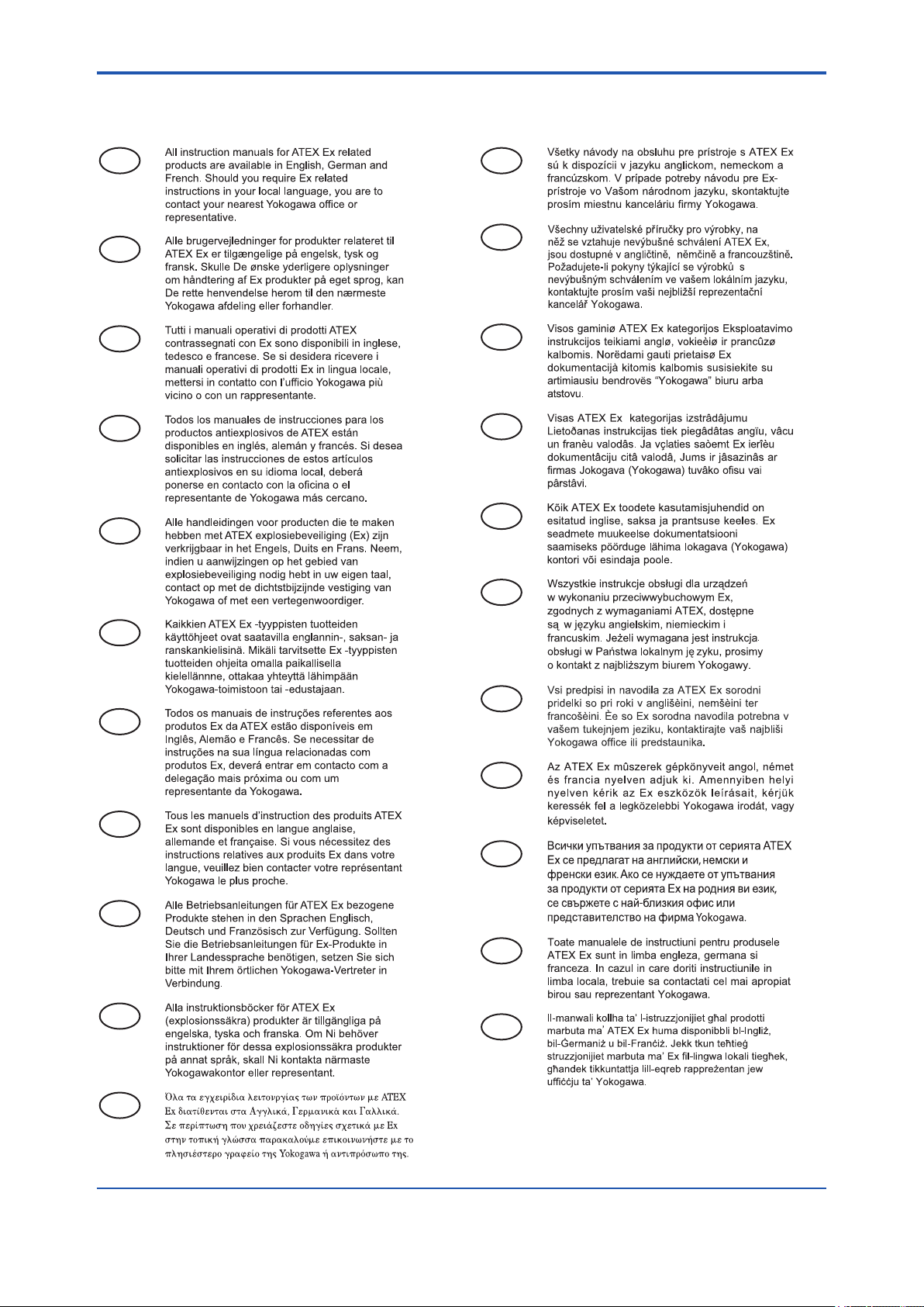
■ ATEX Documentation
This procedure is only applicable to the countries in European Union.
x
GB
DK
E
NL
SK
CZ
I
LT
LV
EST
PL
SF
P
F
D
S
SLO
H
BG
RO
M
GR
IM 21B04C01-01E
Page 12

<1. Notes on Handling>
1. Notes on Handling
1-1
The YVP110 advanced valve positioner is fully
factory-tested upon shipment. When the YVP110 is
delivered, visually check that no damage occured
during the shipment.
1.1 Nameplate
The model name and conguration are indicated
on the nameplate. Verify that the conguration
indicated in the “Model and Sufx Code” in Chapter
7 is in compliance with the specications written on
the order sheet.
F0101.ai
Figure 1.1 Nameplate
1.2 Transport
To prevent damage while in transit, leave the
positioner in the original shipping container until it
reaches the installation site.
(3) The performance of the positioner may be
impaired if stored in an area exposed to direct
rain and water.
To avoid damage to the positioner, install it
immediately after removal from the shipping
container. Follow wiring instructions in this
manual.
1.4 Choosing the Installation Location
Although the advanced valve positioner is
designed to operate in a vigorous environment,
to maintain stability and accuracy, the following is
recommended:
(1) Ambient Temperature
It is preferable not to expose the instrument
to extreme temperatures or temperature
uctuations. If the instrument is exposed to
radiation heat a thermal protection system and
appropriate ventilation is recommended.
(2) Environmental Requirements
Do not allow the positioner to be installed
in a location that is exposed to corrosive
atmospheric conditions. When using the
positioner in a corrosive environment, ensure
the location is well ventilated. The unit and its
wiring should be protected from exposure to
rainwater.
1.3 Storage
When an extended storage period is expected,
observe the following precautions:
(1) If at all possible, store the positioner in factory-
shipped condition, that is, in the original
shipping container.
(2) Choose a storage location that satises the
following requirements.
• A location that is not exposed to rain or water.
• A location subject to a minimum of vibration or
impact.
• The following temperature and humidity range
is recommended. Ordinary temperature and
humidity (25°C, 65%) are preferable.
Temperature: –40 to 85°C
Humidity: 5 to 100% RH (at 40°C)
(3) Impact and Vibration
It is recommended that the positioner is
installed in a location that is subject to a
minimum amount of impact and vibration.
1.5 Use of a Transceiver
Although the positioner is designed to resist
inuence from high frequency noise, use of a
transceiver in the vicinity of installation may cause
problems. Installing the transmitter in an area free
from high frequency noise (RFI) is recommended.
IM 21B04C01-01E
Page 13

<1. Notes on Handling>
1-2
1.6 Insulation Resistance Test and Withstand Voltage Test
CAUTION
(1) Overvoltage of the test voltage that is so
small that it does not cause an dielectric
breakdown may in fact deteriorate insulation
and lower the safety performance; to prevent
this it is recommended that the amount of
testing be kept to a minimum.
(2) The voltage for the insulation resistance test
must be 500V DC or lower, and the voltage
for the withstand voltage test must be 500V
AC or lower. Failure to heed these guidelines
may cause faulty operation.
(3) Where a built-in arrester is provided (sufx
code: /A), the voltage for the insulation
resistance test must be 100V DC or lower,
and the voltage for the withstand voltage test
must be 100V AC or lower. Failure to heed
these guidelines may cause faulty operation.
Withstand voltage test procedure
Testing between the input terminals and the
grounding terminal
1. Lay the transition wiring between the + terminal
and the − terminal, and connect the withstand
voltage tester (with the power turned OFF)
between the transition wiring and the grounding
terminal. Connect the grounding side of the
withstand voltage tester to the grounding
terminal.
2. After setting the current limit value of the
withstand voltage tester to 10 mA, turn
the power ON, and gradually increase the
impressed voltage from 0 V to the specied
value.
3. The voltage at the specied value must remain
for a duration of one minute.
4. Upon completion of the test, carefully reduce
the voltage so that no voltage surge occurs.
1.7 Notes for Saftey
Follow the steps below to perform the test, the
wiring of the communication line must be removed
before initiating testing.
Insulation resistance test procedure
1. Lay transition wiring between the + terminal and
the − terminal.
2. Connect the insulation resistance meter (with
the power turned OFF) between the transition
wiring of Step 1 above and ground terminal.
The polarity of the input terminals must be
positive and that of the ground must be
negative.
3. Turn the power of the insulation resistance
meter ON and measure the insulation
resistance. The duration of the applied voltage
must be the period during which 100 MΩ
or more is conrmed (or 20 MΩ if the unit is
equipped with a built-in arrester).
4. Upon completion of the test, remove the
insulation resistance meter, connect a 100
kΩ resistor between the transition wiring, and
allow the electricity to discharge. Do not touch
the terminal with your bare hands while the
electricity is discharging for more than one
second.
CAUTION
When air is supplied to a valve, do not touch
the moving part (a stem of the valve), as it may
suddently move.
CAUTION
• While A/M selection switch is set to manual
side (M), the pressure set in the regulator
for air supply will be directly output to the
actuator regardless of the control signal.
Before changing the mode from auto to
manual, check and conrm thoroughly that
there will be no effect which may cause
a danger in process or personal injury by
changing the mode.
• Do not change the mode by using auto/
manual switch during the operation. If the
mode is changed from auto to manual or
manual to auto, the valve stem will happnen
to move to the position which is different
from the control signal (the input signal to the
positioner), and thus dangerous.
• As soon as the manual operation is nished,
make it sure to change the mode to auto by
moving the A/M selection switch to Auto(A)
side.
IM 21B04C01-01E
Page 14

<1. Notes on Handling>
1-3
1.8 EMC Conformity Standards
EN61326-1 Class A, Table 2 (For use in industrial
locations)
CAUTION
This instrument is a Class A product, and it is
designed for use in the industrial environment.
Please use this instrument in the industrial
environment only.
1.9 Installation of Explosion Protected Type Positioner
CAUTION
To preserve the safety of explosionproof
equipment requires great care during mounting,
wiring and piping. Safety requirements also
place restrictions on maintenance and repair
activities. Please read the following section very
carefully.
1.9.1 FM Certication
or
Rating 2
For Groups A, B, C, D, E, F and G or Group IIC
Maximum Input Voltage Vmax: 17.5 V
Maximum Input Current Imax: 360 mA
Maximum Input Power Pmax: 2.52 W
Maximum Internal Capacitance Ci: 1.76 nF
Maximum Internal Inductance Li: 0 µH
or
Rating 3
For Groups C, D, E, F and G or Group IIB
Maximum Input Voltage Vmax: 17.5 V
Maximum Input Current Imax: 380 mA
Maximum Input Power Pmax: 5.32 W
Maximum Internal Capacitance Ci: 1.76 nF
Maximum Internal Inductance Li: 0 µH
• In the rating 1, the output current of the
barrier must be limited by a resistor “Ra”
such that
Io = Uo/Ra.
• In the rating 2 or 3, the output characteristics
of the barrier must be the type of trapezoid
which are certied as the FISCO model.
• The safety barrier may include a terminator.
• More than one eld instruments may be
connected to the power supply line.
A) FM Intrinsically Safe Type
Cautions for FM Intrinsically safe type. (Following
cotents refer “Doc No. IFM017-A12 P.1, 1-1, 2, 2-1,
and 2-2.”)
Note 1. Model YVP110 Advenced Valve Positioner
with optional code /FS15 are applicable for
use in hazardous locations.
• Applicable standard: FM3600, FM3610,
FM3611, FM3810, ANSI/NEMA250
• Intrinsically safe, with FISCO parameters, for
use in Class I, II, III, Division 1, Groups A, B,
C, D, E, F, G and Class I, Zone 0, AEx ia IIC
• Non-incendive for Class I, Division 2, Groups
A, B, C, D and Class I, Zone 2, Group IIC
• Indoor/Outdoor hazardous locations, NEMA
4X
• Ambient Temperature: –40 to 60°C
Note 2. Electrical Data
Rating 1
For Groups A, B, C, D, E, F and G or Group IIC
Maximum Input Voltage Vmax: 24 V
Maximum Input Current Imax: 250 mA
Maximum Input Power Pmax: 1.2 W
Maximum Internal Capacitance Ci: 1.76 nF
Maximum Internal Inductance Li: 0 µH
Note 3. Installation
• Dust-tight conduit seal must be used
when installed in Class II and Class III
environments.
• Control equipment connected to the
Assoiciated Apparatus must not use or
generate more than 250 Vrms or Vdc.
• Installation should be in accordance with
ANSI/ISA RP12.6 “Installation of Intrinsically
Safe Systems for Hazardous (Classied)
Locations” and the National Electrical Code
(ANSI/NFPA 70) Sections 504 and 505.
• The conguration of Associated Apparatus
must be Factory Mutual Research Approved
under FISCO Concept.
• Associated Apparatus manufacturer’s
installation drawing must be followed when
installing this equipment.
• The YVP series are approved for Class
I, Zone 0, applications. If connecting
AEx[ib] associated Apparatus or AEx ib I.S.
Apparatus to the YVP series the I.S. circuit
is only suitable for Class I, Zone 1, or Class
I, Zone 2, and is not suitable for Class I,
Zone 0, or Class I, Division 1, Hazardous
(Classied) Locations.
IM 21B04C01-01E
Page 15
<1. Notes on Handling>
1-4
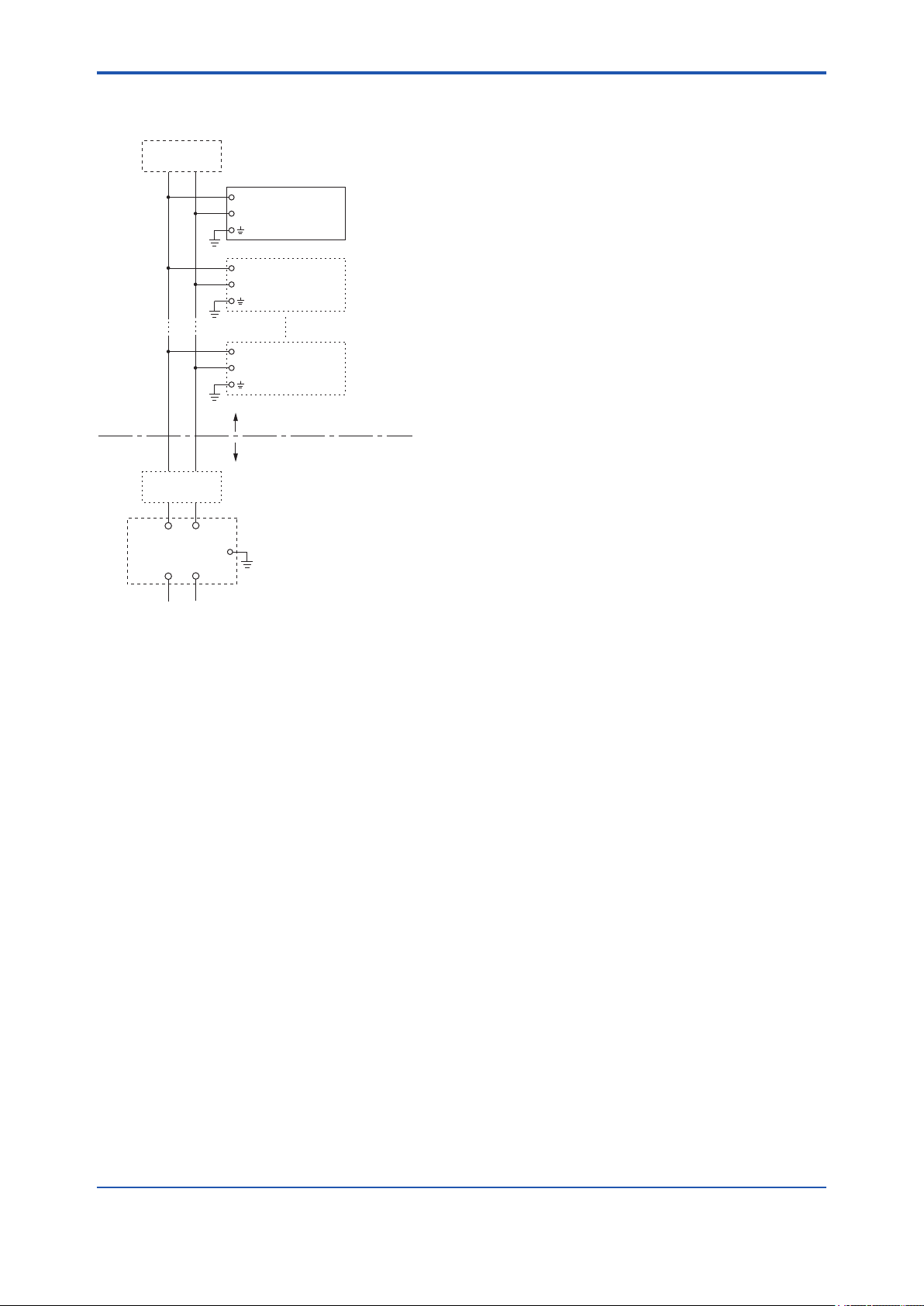
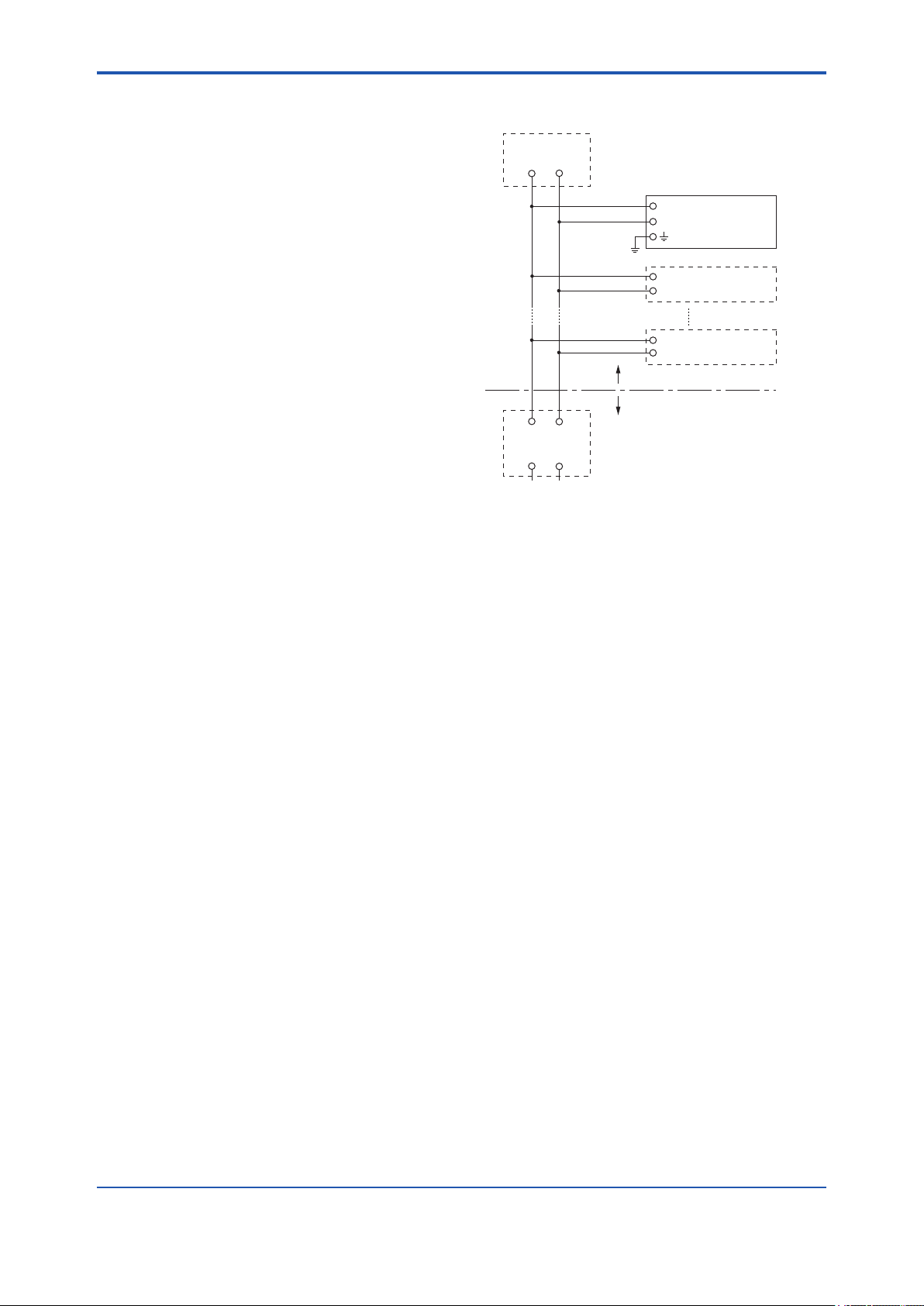
l Installation Diagram (Intrinsically safe,
Division 1 Installation)
Terminator
+
Valve Positioner
−
+
Transmitter
−
+
Transmitter
−
Hazardous Location
Non-hazardous Location
Terminator
−+
Safety Barrier
Note 4. FISCO rules
The FISCO concept allows the interconnection
of intrinsically safe apparatus to associated
apparatus not specically examined in
such combination. The criterion for such
interconnection is that the voltage (Ui), the
current (Ii) and the power (Pi) which intrinsically
safe apparatus can receive and remain
intrinsically safe, considering faults, must be
equal or greater than the voltage (Uo, Voc,
Vt), the current (Io) and the power (Po) which
can be provided by the associated apparatus
(supply unit). In addition, the maximum
unprotected residual capacitance (Ci) and
inductance (Li) of each apparatus (other than
the terminators) connected to the eldbus
must be less than or equal to 5 nF and 10 µH
respectively.
In each I.S. eldbus segment only one active
source, normally the associated apparatus, is
allowed to provide the necessary power for the
eldbus system. The allowed voltage Uo of the
associated apparatus used to supply the bus is
limited to the range of 14 V d.c. to 24 V d.c. All
other equipment connected to the bus cable
has to be passive, meaning that the apparatus
−+
F0102.ai
is not allowed to provide energy to the system,
except to a leakage current of 50 µA for each
connected device.
Supply unit
trapezoidal or rectangular output characteristic
only
Uo = 14 to 24 V (I.S. maximum value)
Io according to spark test result or other
assessment,
e.g. 133 mA for Uo = 15 V (Group IIC, rectangular
characteristic)
No specication of Lo and Co in the
certicate and on the label.
Cable
The cable used to interconnect the devices
needs to comply with the following parameters:
loop resistance R’: 15 to 150 Ω/km
inductance per unit length L’: 0.4 to 1 mH/km
capacitance per unit length C’: 80 to 200
nF/km
C’ = C’ line/line + 0.5 C’ line/screen, if both
lines are oating
or
C’ = C’ line/line + C’ line/screen, if the screen
is connected to one line
length of spur cable: max. 30 m (Group IIC)
or 120 m (Group IIB)
length of trunk cable: max. 1 km (Group IIC)
or 1.9 km (Group IIB)
Terminators
At each end of the trunk cable an approved
line terminator with the following parameters is
suitable:
R = 90 to 100 Ω
C = 0 to 2.2 µF
The resistor must be infallible according to IEC
60079-11. One of the two allowed terminators
might already be integrated in the associated
apparatus (bus supply unit).
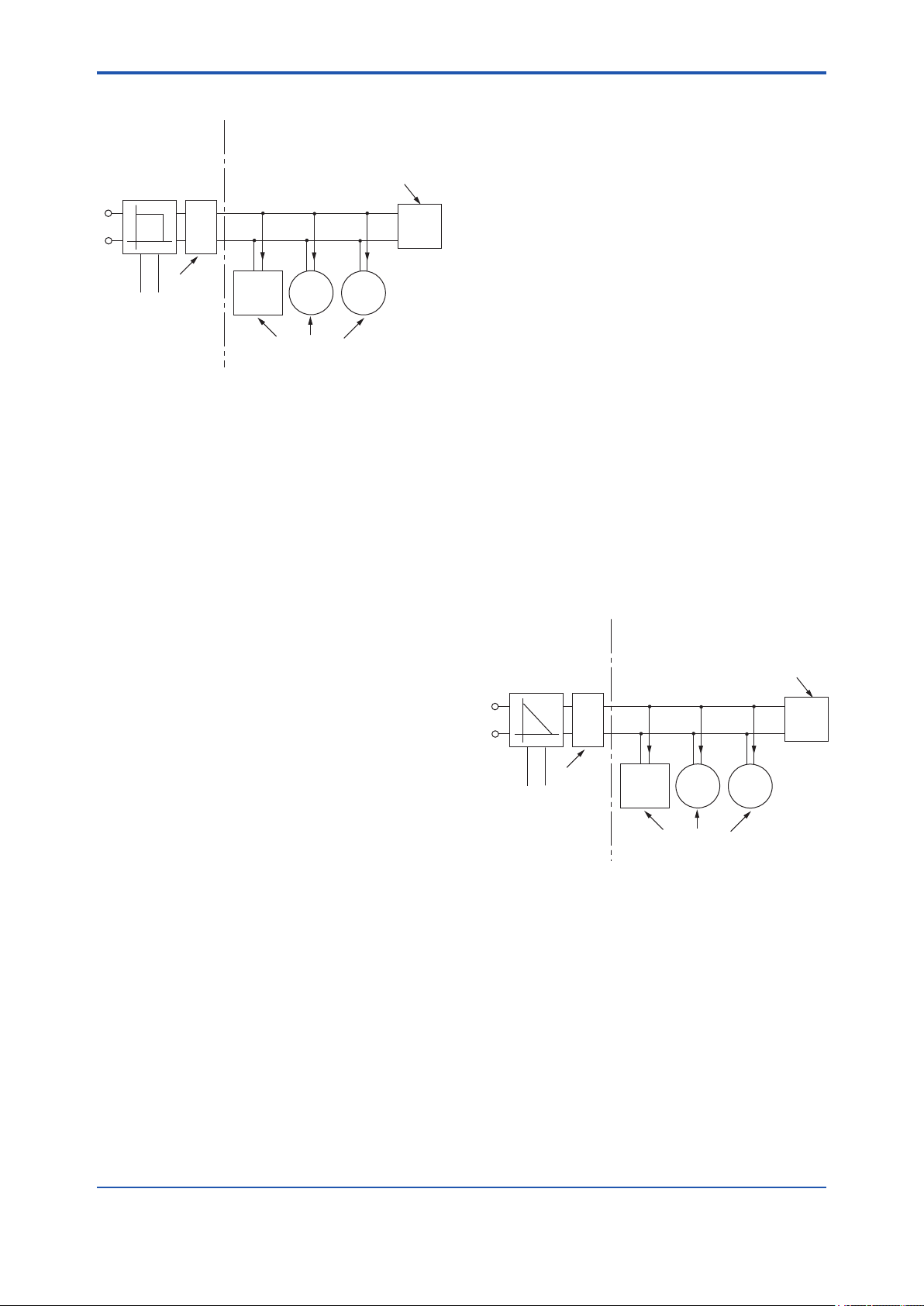
System evaluation
The number of passive devices like
transmitters, actuators, hand held terminals
connected to a single bus segment is not
limited due to I.S. reasons. Furthermore, if the
above rules are respected, the inductance
and capacitance of the cable need not to be
considered and will not impair the intrinsic
safety of the installation.
IM 21B04C01-01E
Page 16
<1. Notes on Handling>
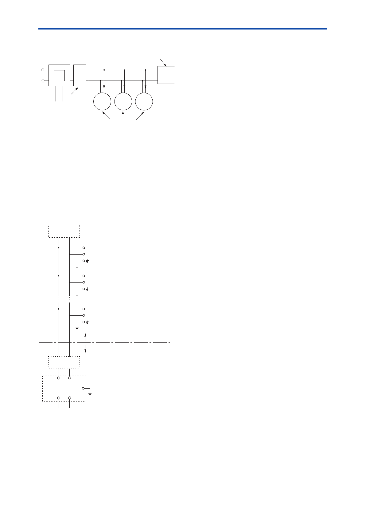
1-5
SAFE AREA HAZARDOUS AREA
Supply Unit
(FISCO Model)
U
U
I
Terminator
Data
Field Instruments
Terminator
(FISCO Model)
Ex i
(Passive)
Note 5. Maintenance and Repair
The instrument modication or parts
replacement by other than authorized
representative of Yokogawa Electric
Corporation is prohibited and will void Factory
Mutual Intrinsically Safe and Non-incendive
Approval.
l Installation Diagram (Nonincendive,
Division 2 Installation)
Terminator
+
Valve Positioner
−
+
Transmitter
−
F0103.ai
*1: Dust-tight conduit seal must be used when
installed in Class II and Class III environments.
*2: Installation should be in accordance with the
National Electrical Code® (ANSI/NFPA 70)
Sections 504 and 505.
*3: The conguration of Associated Nonincendive
Field Wiring Apparatus must be FM Approved.
*4: Associated Nonincendive Field Wiring
Apparatus manufacturer’s installation
drawing must be followed when installing this
equipment.
*5: No revision to drawing without prior FM
Approvals.
*6: Terminator and supply unit must be FM
Approved.
*7: If use ordinary wirings, the general purpose
equipment must have nonincendive eld wiring
terminal approved by FM Approvals.
*8: The nonincendive eld wiring circuit concept
allows interconection of nonincendive eld
wiring apparatus with associated nonincendive
eld wiring apparatus, using any of the wiring
methods permitted for unclassied locations.
*9: Installation requirements;
Vmax ≥ Voc or Vt
Imax = see note 10.
Ca ≥ Ci + Ccable
La ≥ Li + Lcable
*10: For this current controlled circuit, the parameter
(Imax) is not required and need not be aligned
with parameter (Isc or It) of the barrier or
associated nonincendive eld wiring apparatus.
Terminator
(Nonincendive)
Power Supply
+
Transmitter
−
Hazardous Location
Non-hazardous Location
FM Approved Associated
Nonincendive Field Wiring Apparatus
Vt or Voc
It or Isc
Ca
La
F0104.ai
Electrical Data:
Maximum Input Voltage Vmax: 32 V
Maximum Internal Capacitance Ci: 1.76 nF
Maximum Internal Inductance Li: 0 µH
B) FM Explosionproof Type
Caution for FM explosionproof type.
Note 1. Model YVP110 Valve Positioner with
optional code /FF1 are applicable for use in
hazardous locations.
• Applicable standard: FM3600, FM3615,
FM3810, ANSI/NEMA250
• Explosionproof for Class I, Division 1,
Groups A, B, C and D
• Dust-ignitionproof for Class II/III, Division 1,
Groups E, F and G
• Enclosure Rating: NEMA 4X
• Temperature Class: T6
• Ambient Temperature: –40 to 80°C
IM 21B04C01-01E
Page 17
<1. Notes on Handling>
1-6
Note 2. Wiring
• All wiring shall comply with National Electrical
Code ANSI/NEPA70 and Local Electrical
Codes.
• “FACTORY SEALED, CONDUIT SEAL NOT
REQUIRED.”
Note 3. Operation
• Note a warning label worded as follows;
WARNING: OPEN CIRCUIT BEFORE
REMOVING COVER.
• Take care not to generate mechanical spark
when accessing to the instrument and
peripheral devices in hazardous locations.
Note 4. Maintenance and Repair
• The instrument modication or parts
replacement by other than authorized
representative of Yokogawa Electric
Corporation is prohibited and will void
the approval of Factory Mutual Research
Corporation.
C) FM Nonincendive approval
Model YVP110 Advanced Valve Positioner with
optional code /FN15.
• Applicable standard: FM3600, FM3611,
FM3810
• Nonincendive Approval
Class I, Division 2, Groups A, B, C and D
Class II, Division 2, Groups F and G
Class III, Division 1 and
Class I, Zone 2, Group IIC in Hazardous
(Classied) Locations.
Temperature Class: T4
Ambient Temperature: –40 to 60°C
Enclosure: NEMA Type4X
• Electrical Parameters:
Vmax = 32 Vdc
Ci = 1.76 nF
Li = 0 µ H
• Caution for FM Nonincendive type.
(Following contents refer to “DOC. No.
NFM010-A12 p.1 and p.2”)
NFM010-A12
Installation Diagram:
Terminator
+
YVP
−
Valve Positioner
+
Field Instruments
−
+
Field Instruments
−
Hazardous Area
Safe Area
Nonincendive
Power Supply
F0105.ai
Note 1.
Dust-tight conduit seal must be used when
installed in Class II and Class III environments.
Note 2.
Installation should be in accordance with
National Electrical Code (ANSI/NFPA 70)
Sections 504, 505 and Local Electrical Code.
Note 3.
The conguration of Associated Apparatus must
be Factory Mutual Research Approved.
Note 4.
Associated Apparatus manufacturer's
installation drawing must be followed when
installing this equipment.
Note 5.
No revision to drawing without prior Factory
Mutual Research Approval.
Note 6.
Terminator and supply unit must be FM
approved.
Note 7.
Installation requirements;
Vmax ≥ Voc or Vt
Ca ≥ Ci + Ccable
La ≥ Li + Lcable
IM 21B04C01-01E
Page 18

<1. Notes on Handling>
1-7
1.9.2 ATEX Certication
WARNING
• Do not open the cover when energized.
• When the ambient temp.≥70°C,
Use the heat-resisting cable≥90°C
• Take care not to generate mechanical
sparking when access to the instrument and
peripheral devices in hazardous locations.
• Electrostatic charge may cause an explosion
hazard.
Avoid any actions that cause the generation
of electrostatic charge, such as rubbing with
a dry cloth on coating face of product.
(1) Technical Data
A) ATEX Intrinsically Safe Type (Ex ia)
Caution for ATEX Intrinsically Safe Type.
NOTE
Degree of Protection of the Enclosure: IP65
Electrical Parameters:
For Ex ia IIC or Ex iaD
Ui = 24.0 V, Ii = 250 mA, Pi = 1.2 W,
Cint = 1.76 nF, Lint = 0 μH
or
For Ex ia IIB/ IIC or Ex iaD (FISCO model)
Ui = 17.5 V, Ii = 380 mA, Pi = 5.32 W,
Cint = 1.76 nF, Lint = 0 μH
For II 1D Ex tD
Input signal: 32 Vdc,
Output current: 17 mA
Note 3. Installation
All wiring shall comply with local installation
requirements.
(Refer to the installation diagram)
Note 4. Maintenance and Repair
The instrument modication or parts
replacement by other than authorized
representative of Yokogawa Electric
Corporation is prohibited and will void KEMA
Intrinsically safe Certication.
Keep the safety use conditions for both 1G and
1D when used in the hazardous gas and dust
area.
Note1. Model YVP110 Advanced Valve Positioner
with optional code /KS25 for potentially
explosive atmospheres:
• Applicable standard: EN60079-0:2006,
EN60079-11:2007, EN60079-26:2007,
EN60079-27:2006, EN61241-0:2006,
EN61241-1:2004, EN61241-11:2006 and
EN60529
• Certicate: KEMA 08ATEX0114 X
Note 2. Ratings
Type of Protection:
II 1G Ex ia IIB/IIC T4
II 1D Ex iaD 20 IP65 T100°C
II 1D Ex tD A20 IP65 T100°C
Maximum Surface Temperature for dust proof.:
T100°C
Ambient Temperature Ex ia or Ex iaD:
–40°C to +60°C
Ambient Temperature Ex tD: –40°C to +80°C
Ambient Humidity: 0 to 100%RH
(No condensation)
Note 5. Special Conditions for Safe Use
Because the enclosure of the Valve Positioner
is made of aluminium, if it is mounted in an area
where the use of category 1G apparatus is
required, it must be installed such, that, even in
the event of rare incidents, ignition sources due
to impact and friction sparks are excluded.
Once used as apparatus of equipment category
1D in type of protection Ex tD, the valve
positioner is no longer suitable as apparatus
of equipment category 1G or 1D in type of
protection Ex ia or Ex iaD.
Note 6. Installation Instructions
When used in a potentially explosive
atmosphere, requiring the use of apparatus of
equipment category 1D, suitable certied cable
entry devices or certied blanking elements
with a degree of ingress protection of at least
IP6X according to EN 60529 shall be used and
correctly installed.
Note 7. Installation
When used in potentially explosive atmosphere
for category 1D, need not use safety barrier.
IM 21B04C01-01E
Page 19
<1. Notes on Handling>
1-8
FISCO Model
Non-hazardous
Locations
Supply Unit
(FISCO Model)
U
U
I
Terminator
Data
I.S. eldbus system complying with FISCO
The criterion for such interconnection is that the
voltage (Ui), the current (Ii) and the power (Pi),
which intrinsically safe apparatus can receive,
must be equal or greater than the voltage (Uo),
the current (Io) and the power (Po) which can be
provided by the associated apparatus (supply unit).
In addition, the maximum unprotected residual
capacitance (Ci) and inductance (Li) of each
apparatus (other than the terminators) connected
to the eldbus line must be equal or less than 5 nF
and 10 µH respectively.
Supply unit
The supply unit must be certied by a notied body
as FISCO model and following trapezoidal output
characteristic is used.
Uo = 14 to 24 V (I.S. maximum value)
Io based on spark test result or other assessment,
ex. 133 mA for Uo = 15 V (Group IIC)
The maximum allowed Co and Lo are determined
by the combinations as specied below.
Cable
The cable used to interconnect the devices needs
to comply with the following parameters:
loop resistance R': 15 to 150 Ω/km
inductance per unit length L': 0.4 to 1 mH/km
capacitance per unit length C': 80 to 200 nF/km
C' = C' line/line + 0.5 C' line/screen, if both lines
are oating
Hazardous Locations
Terminator
(FISCO Model)
Ex i
Hand-
held-
Terminal
Field Instruments
(Passive)
F0106.ai
or
C' = C' line/line + C' line/screen, if the screen is
connected to one line
length of spur cable: max. 30 m (Ex ia IIC T4) or
120 m (Ex ia IIB T4)
length of trunk cable: max. 1 km (Ex ia IIC T4)
or 1.9 km (Ex ia IIB T4)
Terminators
The terminator must be certied by a notied body
as FISCO model and at each end of the trunk
cable an approved line terminator with the following
parameters is suitable:
R = 90 to 100 Ω
C = 0 to 2.2 µF
The resistor must be infallible according to EN
50020. One of the two allowed terminators might
already be integrated in the associated apparatus
(bus supply unit).
Number of Devices
The number of devices (max. 32) possible on a
eldbus link depends on factors such as the power
consumption of each device, the type of cable used,
use of repeaters, etc.
Entity Model
Non-hazardous
Locations
Supply Unit
U
U
I
Terminator
Data
I.S. eldbus system complying with Entity model
Hazardous Locations
Ex i
Hand-
held-
Terminal
Field Instruments
(Passive)
Terminator
F0107.ai
IM 21B04C01-01E
Page 20

<1. Notes on Handling>
1-9
I.S. values Power supply-eld device:
Po ≤ Pi, Uo ≤ Ui, Io ≤ Ii
Calculation of max. allowed cable length:
Ccable ≤ Co - ∑ci - ∑ci (Terminator)
Lcable ≤ Lo - ∑Li
Number of Devices
The number of devices (max. 32) possible on a
eldbus link depends on factors such as the power
consumption of each device, the type of cable used,
use of repeaters, etc.
B) ATEX Flameproof Type
Caution for ATEX ameproof type.
Note 1. Model YVP110 Valve Positioner with
optional code /KF2 is applicable for
potentially explosive atmospheres:
• Applicable standard:
EN60079-0:2009, EN60079-1:2007
• Certicate: KEMA 10ATEX0023 X
• Group: II
• Category: 2G
• Type of Protection and Marking Code:
Ex d IIC, T6 or T5 Gb
• Ambient Temperature: T6; –40 to 65°C
T5; –40 to 80°C
Note 2. Electrical Data
• Supply voltage: 32 V DC max.
• Output signal: 17 mA DC
Note 3. Installation Instructions
• The cable glands and blanking elements
shall be certied in type of protection
ameproof enclosure “d” suitable for the
conditions of use and correctly installed.
• With the use of conduit entries a sealing
device shall be provided either in the
ameproof enclosure or immediately on the
entrance thereto.
• To maintain the degree of ingress protection
IP65 according to EN 60529 special care
must be taken to avoid water entering the
breathing and draining device when the valve
positioner is mounted with the feedback shaft
in the upright position.
Note 4. Operation
• Keep strictly the WARNING on the label on
the positioner.
AFTER DE-ENERGIZING, DELAY 5
MINUTES BEFORE OPENING.
WHEN THE AMBIENT TEMP. ≥ 70°C,
USE HEAT-RESISTING CABLE & CABLE
GLAND ≥ 90°C.
Note 5. Maintenance and Repair
• The instrument modication or parts
replacement by other than authorized
representative of Yokogawa Electric
Corporation is prohibited and will void KEMA
Flameproof Certication.
C)
ATEX Intrinsically safe (Ex ic)/Type n (Ex nA)
Note 1. Model YVP110 Advanced Valve Positioner
with optional code /KN25
• Applicable standard:
EN60079-0:2009/EN60079-0:2012(Ex ic/Ex
nA), EN60079-11:2012(Ex ic)
EN60079-15:2010(Ex nA)
• Ex ic: II 3G Ex ic IIC T4 Gc (Intrinsically safe)
• Ex nA: II 3G Ex nA IIC T4 Gc (Non-sparking)
• Ambient Temperature: -30 to 75°C
• Ambient Humidity:
0 to 100%RH (No condensation)
• Enclosure: IP65
• Installation category: I
Note 2. Electrical Data
• Ex ic: Ui = 32 V, Ci = 3.52 nF, Li = 0 μH
• Ex nA: 32 V DC MAX
Note 3. For the installation of this positioner, once
a particular declared type of protection
is selected, the other type of protection
cannot be used. The installation must be in
accordance with the description about type
of protection in this instruction manual.
Note 4. In order to avoid confusion, unnecessary
marking is crossed out on the label other
than the selected type of protection when
positioner is installed.
Note 5. Installation Instructions
• Cable glands, adapters and/or blanking
elements shall be of Ex “n”, EX “e” or Ex “d”
and shall be installed so as to maintain the
specied degree of protection (IP Code) of
the equipment.
• To maintain the degree of protection IP65
according to IEC 60529, special care must
be taken to avoid water.
Note 6. Maintenance and Repair
• The instrument modication or parts
replacement by other than authorized
representative of Yokogawa Electric
Corporation is prohibited and will void ATEX
Ex ic and Ex nA.
IM 21B04C01-01E
Page 21
<1. Notes on Handling>
1-10
Note 7. Ex ic Installation
• All wiring shall comply with local installation
requirements (refer to the installation
diagram)
Installation Diagram
Hazardous Area
Valve Positioner
+
−
Non-hazardous Area
Associated Apparatus
+
−
Electrical Data: Ui = 32 V
Ci = 3.52 nF
Li = 0 μH
Note 8. Ex ic Specic Conditions of Use
WARNING
• Electrostatic charge may cause an explosion
hazard. Avoid any actions that cause the
generation of electrostatic charge, such as
rubbing with a dry cloth on coating face of
product.
• When the lightning protector option is
specied (/A), the apparatus is not capable
of withstanding the 500V insulation test
required by EN60079-11. This must be taken
into account when installing the apparatus.
• WHEN THE AMBIENT TEMP.≥70°C, USE
THE HEAT-RESISTING CABLE AND
CABLE GRAND≥90°C
• POTENTAIAL ELECTROSTATIC
CHARGING HAZARD – SEE USER’S
MANUAL
F0108.ai
Note 10. Ex nA Specic Conditions of Use
WARNING
• Electrostatic charge may cause an explosion
hazard. Avoid any actions that cause the
generation of electrostatic charge, such as
rubbing with a dry cloth on coating face of
product.
• WHEN THE AMBIENT TEMP.≥70°C, USE
THE HEAT-RESISTING CABLE AND
CABLE GRAND≥90°C
• POTENTAIAL ELECTROSTATIC
CHARGING HAZARD – SEE USER’S
MANUAL
• DO NOT OPEN IN AN EXPLOSIVE
ATMOSPHERE WHEN ENERGIZED
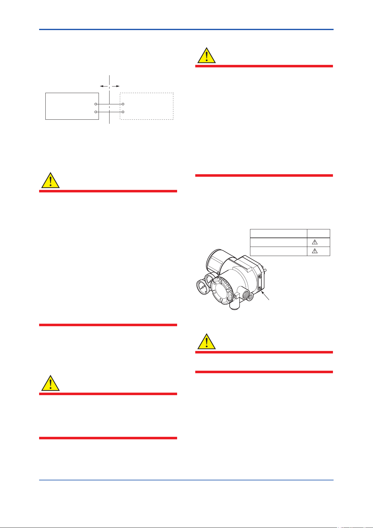
(2) Electrical Connection
The type of electrical connection is stamped near
the electrical connection port according to the
following marking.
Screw Size Marking
ISO M20
ANSI 1/2 NPT female
× 1.5 female
Location of the marking
M
N
F0109.ai
(3) Installation
Note 9. Ex nA Installation
• Screws of terminals for eld wiring
connections shall be tightened with specied
torque values: 1.2 N·m
WARNING
When using a power supply not having a
nonincendive circuit, please pay attention not to
ignite in the surrounding ammable atmosphere.
In such a case, we recommend using wiring
metal conduit in order to prevent the ignition.
WARNING
All wiring shall comply with local installation
requirement and local electrical code.
IM 21B04C01-01E
Page 22
<1. Notes on Handling>
1-11
The grounding terminals are located on the inside
and outside of the terminal area.
Connect the cable to grounding terminal in
accordance with wiring procedure 1) or 2).
1) Internal grounding
terminal
2) External grounding
terminal
F0111.ai
Wiring Procedure for Grounding Terminals
(4) Operation
WARNING
• OPEN CIRCUIT BEFORE REMOVING
COVER. INSTALL IN ACCORDANCE WITH
THIS USER’S MANUAL
• Take care not to generate mechanical
sparking when access to the instrument and
peripheral devices in hazardous locations.
• Electrostatic charge may cause an explosion
hazard.
Avoid any actions that cause the generation
of electrostatic charge, such as rubbing with
a dry cloth on coating face of product.
• Carbon disulphide is excluded for enclosures
under gas atmosphere.
(5) Maintenance and Repair
WARNING
The instrument modication or parts replacement
by other than authorized Representative of
Yokogawa Electric Corporation is prohibited and
will void the certication.
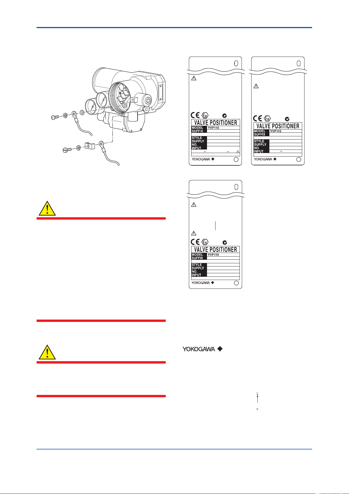
(6) Name Plate
● Name plate for
intrinsically safe type
F91 76LL
YV P KS2 5
WARNING
DON'T OPEN WHEN ENERGIZED.
WHEN THE AMBIENT TEMP. ≥70°C
USE THE HEAT-RESISTING CABLE ≥90°C
No. KEMA 08ATEX0114 X
II 1G Ex ia IIB/IIC T4
II 1D Ex iaD 20 IP65 T100°C
II 1D Ex tD A20 IP65 T100°C
ENCLOSURE:IP65
For II 1G Ex ia IIC or II 1D Ex iaD
Ui=24V Ii=250mA Pi=1.2W Ci=1.76nF Li=0µH
For II 1G Ex ia IIC/IIB or II 1D Ex iaD (FISCO field device)
Ui=17.5V Ii=380mA Pi=5.32W Ci=1.76nF Li=0µH
For II 1D Ex tD
Input signal:32V Output current:17mA
0344
9-17.5(24)V DC (Ex ia, iaD) 9-32.0V DC (Ex tD)
TOKYO 180-8750 JAPAN
Tamb: −40 to 60°C
Tamb: −40 to 60°C
Tamb: −40 to 80°C
II 1G,1D
Foundation Fieldbus
*3
Made in Japan
N200
● Name plate for
/KN25 (Ex ic, Ex nA)
F91 76MQ
YV P KN2 5
WARNING
WHEN THE AMBIENT TEMP.≥70°C,
USE THE HEAT-RESISTING CABLE & CABLE GLAND ≥90°C.
POTENTIAL ELECTROSTATIC CHARGING HAZARD.
- SEE USER’S MANUAL
DO NOT OPEN IN AN EXPLOSIVE ATMOSPHERE WHEN
ENERGIZED
Ex nA IIC T4 Gc
Tamb −30 TO 75°C
ENCLOSURE : IP 65
SUPPLY 32V DC MAX
CROSS OUT UNNECESSARY MARKING OTHER
THAN THE SELECTED TYPE OF PRPTECTION
TOKYO 180-8750 JAPAN
Ex ic IIC T4 Gc
Tamb −30 TO 75°C
ENCLOSURE : IP 65
Ui=32V, Ci=3.52nF, Li=0µH
II 3G
Foundation Fieldbus
N200
*3
Made in Japan
● Name plate for
flameproof type
F91 76LK
YV P KF2
WARNING
AFTER DE-ENERGIZING, DELAY 5 MINUTES
BEFORE OPENING.
WHEN THE AMBIENT TEMP.≥70°C,
USE THE HEAT-RESISTING CABLE & CABLE GLAND ≥90°C.
POTENTIAL ELECTROSTATIC CHARGING HAZARD.
SEE USER’S MANUAL BEFORE USE.
No. KEMA 10ATEX0023X
Ex d IIC T6,T5 Gb
SUPPLY 32V DC MAX
Tamb −40 TO 65°C(T6),80°C(T5)
ENCLOSURE : IP 65
0344
TOKYO 180-8750 JAPAN
II 2G
9 - 32 V DC Foundation Fieldbus
*3
Made in Japan
N200
F0110.ai
MODEL: Specied model code.
SUFFIX: Specied sufx code.
STYLE: Style code.
SUPPLY: Air supply pressure.
NO.: Serial number and year of production*1.
INPUT: Type of electrical input (FOUNDATION
FIELDBUS).
TOKYO 180-8750 JAPAN:
The manufacturer name and the address*2.
*1: The third gure from the last of the serial number shows
the year of production. For example, the production year
of the product engraved in “NO.” column on the name
plate as follows is 2001.
12A220566 108
The year 2001
*2: “180-8750” is a zip code which represents the following
address.
2-9-32 Nakacho, Musashino-shi, Tokyo Japan
*3: The production year is shown on the place of *3 (for
example “2013.02).”
IM 21B04C01-01E
Page 23

<1. Notes on Handling>
1-12
1.9.3 CSA Certication
A) CSA Explosionproof Type
Cautions for CSA Explosionproof type.
Note 1. Model YVP110 Advanced Valve Positioner
with optional code /CF1 are applicable for
use in hazardous locations:
• Applicable standard: C22.2 No. 0, No. 0.4,
No. 0.5, No. 25, No. 30, No. 94, No. 1010.1
• Certicate: 1186507
• Explosionproof for Class I, Groups B, C and
D; Class II, Groups E, F and G; Class III.
• Enclosure Rating: Type 4X
• Temperature Code: T6 and T5
• Ambient Temperature: –40 to 75°C for T6,
–40 to 82°C for T5
Note 2. Wiring
• All wiring shall comply with National Electrical
Code ANSI/NFPA 70 and Local Electrical
Codes.
• “FACTORY SEALED, CONDUIT SEAL NOT
REQUIRED.”
• When the ambient temperature is 60°C
or more, use an external cable having a
maximum allowable heat-resistance of at
least 90°C.
1.9.4 TIIS Certication
A) TIIS Flameproof Type
The model YVP110 Valve Positioner with optional
code /JF3, which has obtained certication
according to technical criteria for explosionprotected construction of electric machinery and
equipment (Standards Notication No. 556 from
the Japanese Ministry of Labor) conforming to IEC
standards, is designed for hazardous areas where
inammable gases or vapors may be present. (This
allows installation in Division 1 and 2 areas)
To preserve the safety of ameproof equipment
requires great care during mounting, wiring, and
piping. Safety requirements also place restrictions
on maintenance and repair activities. Users
absolutely must read “Installation and Operating
Precautions for JIS Flameproof Equipment” at the
end of this manual.
CAUTION
When selecting cables for TIIS ameproof type
positioners, use cables having a maximum
allowable heat resistance of at least 70°C.
Note 3. Maintenance and Repair
• The instrument modication or parts
replacement by other than authorized
representative of Yokogawa Electric
Corporation is prohibited and will void CSA
Certication.
IM 21B04C01-01E
Page 24
<2. Part Names>
2. Part Names
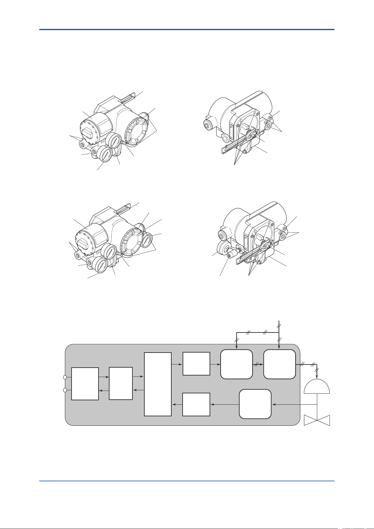
2.1 Appearance and Part Names
2-1
Single Acting Type
Name plate
Air supply
connection
Output pressure
connection
Output pressure
gauge (Optional)
Double Acting Type
Name plate
Air supply
connection
Output pressure
connection
Output pressure
gauge (Optional)
Feedback lever (Optional)
Terminal cover
Electrical
connection
Ground terminal
Air supply pressure gauge
(Optional)
Feedback lever (Optional)
Terminal cover
Output pressure
connection
Output pressure
gauge (Optional)
Electrical
connection
Ground terminal
Air supply pressure gauge
(Optional)
For M8 mounting bolt
Output pressure
gauge (Option)
Output pressure
connection
For mounting
(Normally not used)
Air supply connection
Feedback shaft
Control relay
For mounting
(Normally not used)
Air supply
connection
Feedback shaft
Control relay
For M8 mounting bolt
F0201.ai
2.2 Block Diagram
YVP110
Fieldbus
Commu-
nication
Circuit
Regulator
Fieldbus
Modem
CPU
Digital
Processing
Unit
D/A
Conversion
A/D
Conversion
I/P Module
Supply Air Pressure
Control
Relay
Position
Sensor
F0202.ai
IM 21B04C01-01E
Page 25
<3. Installing YVP110 on Actuator>
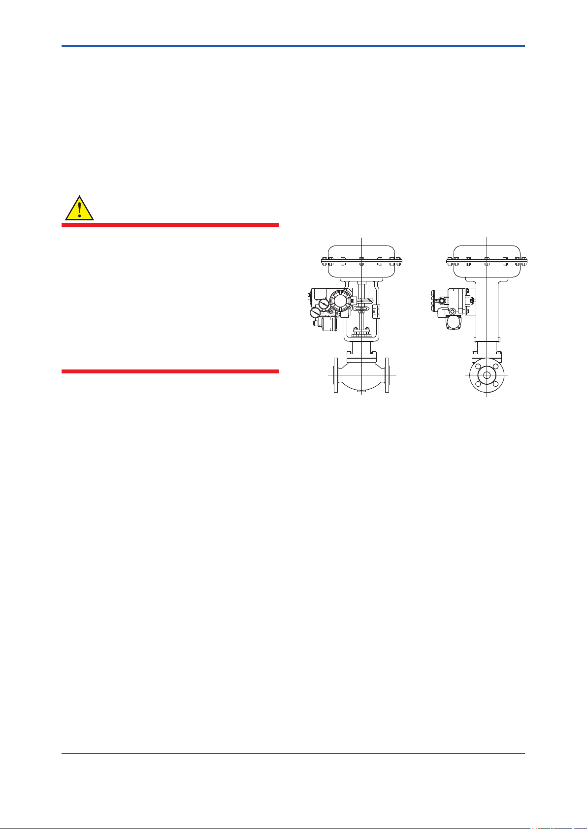
3. Installing YVP110 on Actuator
3-1
3.1 General
For installation of a YVP110, see Section 1.4,
“Choosing the Installation Location.” For the
ambient, environmental conditions required
for installation, see Chapter 7, “General
Specications.”
WARNING
To avoid injury or the process being affected
when installing or replacing a positioner on a
control valve, ensure that:
• All inputs to the valve actuator and other
accessories of the valve and actuator,
including the air supply and electric signal,
are cut off.
• The process has been shut down or the
control valve is isolated from the process by
using bypass valves or the like.
• No pressure remains in the valve actuator.
3.2.1 Installing YVP110 on Linear-motion Control Valve
The following shows the general installation
procedure when assembling a YVP110 with a
linear-motion control valve (e.g., a globe valve)
combined with a diaphragm actuator or cylinder
actuator. Note that the most suitable procedure
may differ depending on the shapes of the bracket
and valve actuator, and the structure of the
mounting position.
3.2 Installing YVP110 on Actuator
A YVP110 can be installed on a valve actuator with
a mounting bracket. Prepare the bracket and clamp
which are necessary to install the valve, according
to the valve. In general, the installation method is
determined by the combination of the control valve
and positioner as well as by the valve manufacturer
who performs the adjustment. For details, consult
the control valve manufacturer.
Required Tools: To install a YVP110, you need to
prepare:
• Nominal 13-mm open end or box end wrench
for M8 bolts used to x the mounting bracket to
the positioner.
• Nominal 10-mm open end or box end wrench
for M6 bolt used to x the feedback lever to the
shaft.
F0301.ai
Figure 3.1 YVP Installed on Linear-motion Valve/
Actuator
(1) Fixing Bracket to YVP110
Use the four M8 bolts that come with the
YVP110 to tightly x the mounting bracket to
the YVP110. (See “Part Names” on page 2.1)
The installation method is determined by the
combination of the control valve and positioner
as well as by the valve manufacturer who
performs the adjustment. For details, consult
the control valve manufacturer.
IM 21B04C01-01E
Page 26
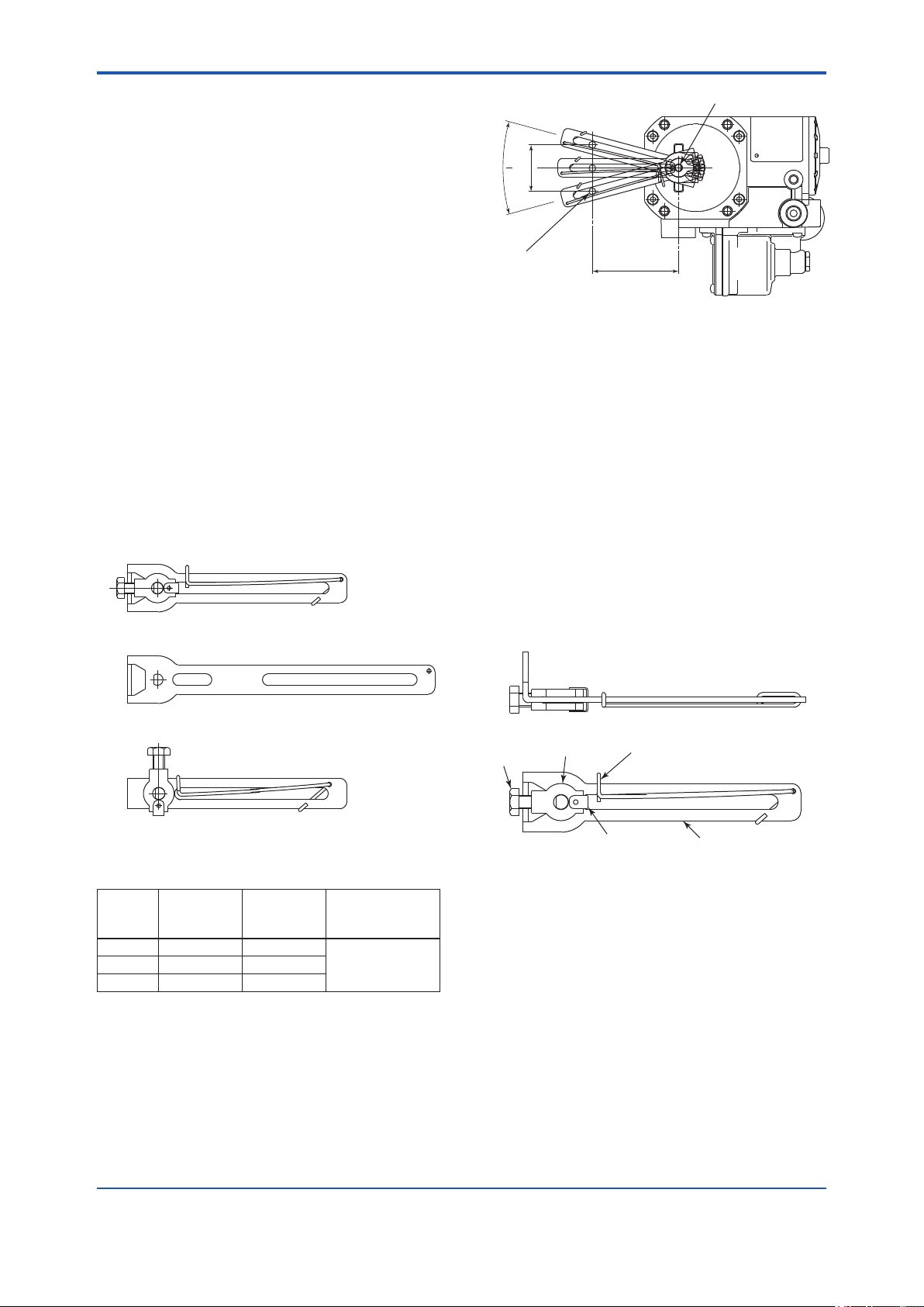
<3. Installing YVP110 on Actuator>
3-2
(2) Fixing the YVP110 to Actuator with Bracket
After xing the bracket to the YVP110, attach it
to the actuator with the specied bolts.
Depending on the shapes of the bracket and
actuator, the working space at the rear of the
YVP110 where the feedback shaft is positioned
may be quite narrow, making installation work
tricky. In such a case, the entire procedure
may be made much easier by attaching
the feedback lever to the feedback shaft as
described in step (3), prior to carrying out step
(2). Check the space behind the YVP110
beforehand.
(3) Attaching Feedback Lever
The YVP110 with option code /LV1 comes with
two different feedback levers, (1) and (2) shown
below, and the one with option code /LV2
comes with lever (3). Check the specications
of the levers shown in Table 3.1 and Figure
3.2 and choose the lever most suitable for the
control valve used.
(1) F9176HA
Feedback shaft
θ
X
SUP
Clamp pin
on side of valve
Figure 3.3 Stroke of Lever
L
F0303.ai
When /LV1 is specied, the hardware for attaching
the lever to the feedback shaft and the spring for
xing the clamp pin are attached to the F9176HA,
the smaller feedback lever for generally used
mid-capacity actuators. Thus, when using the
F9176HC, the feedback lever for high-capacity
actuators, detach and use the hardware and spring
from the F9176HA. See Figure 3.4. To do so, rst
detach the spring <4>. Then, detach the clip <1>
and remove the hardware <2> and <3>. Attach <1>
to <4> to the F9176HC feedback lever for highcapacity actuators in the reverse order.
(2) F9176HC
(3) F9176HD
F0302.ai
Figure 3.2 Feedback Levers
Table 3.1 Specications of Levers
Lever
Model
F9176HA 10 to 60 mm 25 to 75 mm
F9176HD 5 to 20 mm 14 to 20 mm
Note: When assembling a YVP110 with a linear-motion actuator,
Only if the range of the rotation angle is within this
Stroke (X)
ensure that the rotation angle of the YVP110’s feedback
shaft does not exceed the allowable range (10 to 25
degrees shown above.
specication, it is guaranteed that the specied accuracy
can be obtained by linearity correction (see the description
for travel calibration in Section 5.3, “Carrying out Auto
Tuning”).
Pin-to-shaft
Distance (L)
Allowable Range of
Rotation Angle of
Feedback Shaft(θ)
±10 to 25 degreesF9176HC 30 to 100 mm 75 to 115 mm
The hardware and the spring attached to the /LV2
lever is not compatible with those for the /LV1 lever.
<1>
<4>
Lever
F0304.ai
<3>
Figure 3.4 Disassembling a Lever Assembly
<2>
When determining which lever to use, follow the
procedure below to make a linkage between the
YVP110 positioner and control valve’s stem via the
clamp and lever. The adjustment of this linkage is
a decisive factor for determining the characteristics
of the control valve combined with the YVP110
positioner.
(1) Insert the YVP110’s feedback shaft into the
small hole on the stopper side of the lever as
shown in Figure 3.5.
IM 21B04C01-01E
Page 27
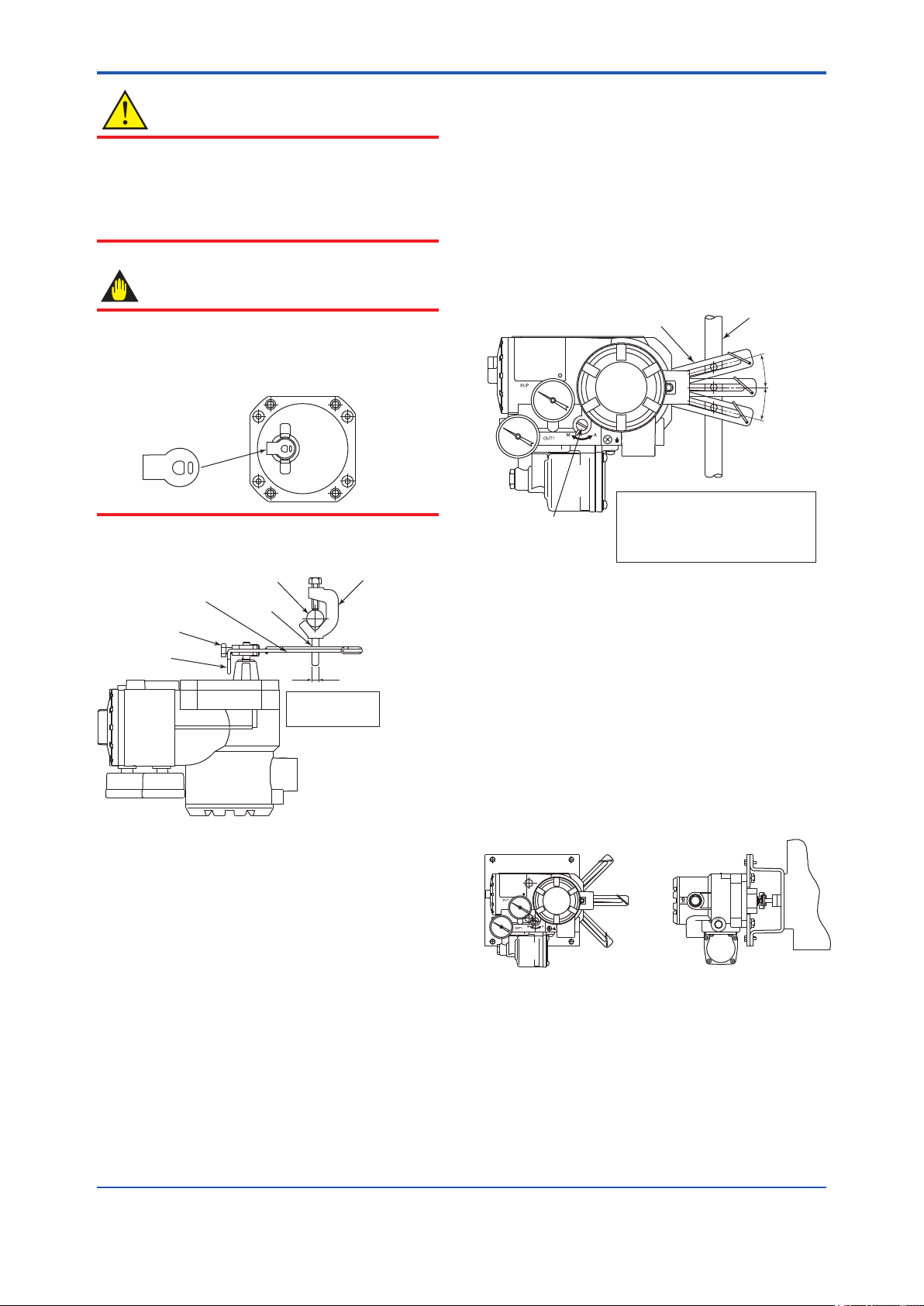
<3. Installing YVP110 on Actuator>
Note that only if the YVP110 is installed at a
CAUTION
position meeting the specication above, it is
guaranteed that the specied accuracy can
It is extremely likely that attaching the lever in the
wrong orientation will cause the feedback shaft
be obtained by linearity correction (see also
Section 13.5, “Travel Calibration”).
to rotate at an angle exceeding its mechanical
limits of ±55 degrees, resulting in the YVP110
being seriously damaged.
When using the Single Acting Type, it is
possible to adjust the position of the feedback
lever while air is being supplied to the actuator.
See Appendix 5. “POSITION ADJUSTMENT
IMPORTANT
A stopper is attached to the feedback shaft to
OF FEEDBACK LEVER”.
Lever
prevent an over-rotation of the shaft as shown
below. When installing the lever, make sure that
you install it on the stopper.
Stopper
3-3
Valve stem
∆θ
F0311.ai
Next, x the lock screw.
Valve stem
Feedback lever
Lock screw
Stopper
Figure 3.5 Attaching Lever and Clamp
Clamp pin
Applicable pin
O.D.: 6 mm
Clamp
F0305.ai
(2) Attach the clamp to the stem in reference with
Figure 3.5. It is necessary to set the clamp
of the YVP110 in a position that allows the
feedback lever to be at an angle within ±15
degrees from the horizontal level when the
valve stem is at the 50% position (see Figure
3.6). Installing the YVP110 at a carefully
determined position, where the feedback lever
is at the horizontal level when the valve stem is
at the 50% position, will make the consequent
installation work easier.
The incline of lever from the
A/M selector switch
Figure 3.6 Checking Position at Which Clamp
Should Be Fixed
horizontal level ∆θ when the stroke
of the stem is 50% must be:
∆θ ≤ ±15 degrees
F0306.ai
3.2.2 Installing YVP110 on Rotary-motion Control Valve
The following shows the general installation
procedure when assembling a YVP110 with
a rotary-motion control valve combined with a
diaphragm actuator or cylinder actuator. Note that
the most suitable procedure may differ depending
on the shapes of the bracket and valve actuator,
and the structure of the actuator.
F0307.ai
Figure 3.7 YVP Installed on Rotary-motion Valve/
Actuator
IM 21B04C01-01E
Page 28
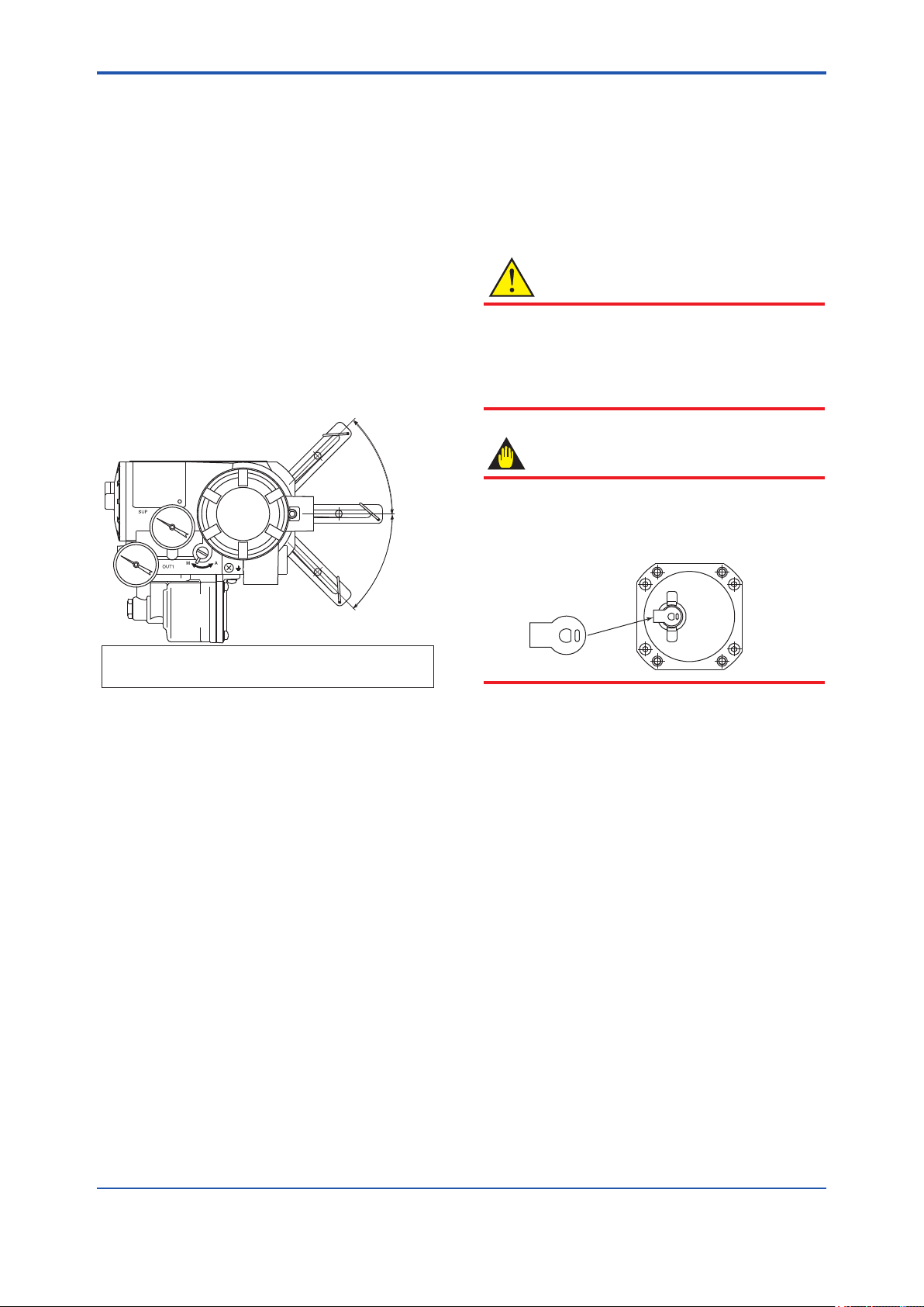
<3. Installing YVP110 on Actuator>
F0308.ai
3-4
(1) Allowable Range of Rotation Angle of
Feedback Shaft
When combining a YVP110 with a rotarymotion actuator, ensure that the rotation of the
feedback shaft by the position feedback meets
the following specications:
• Range of rotation angle of shaft:
Within ±45 degrees from horizontal level
• Minimum span: 20 degrees
• Maximum span: 90 degrees
• Mechanically allowable rotation angle:
±55 degrees
If any one or more of the specications above
are not met, the specied accuracy may not be
guaranteed, resulting in the YVP110 positioner
being damaged. An advance check is essential.
θ
(3) Attaching Feedback Lever
For a rotary-motion actuator, since it is often
difcult to secure sufcient working space
between the positioner and actuator, attach the
feedback lever before xing the YVP110 to the
actuator. Make sure that the stopper is located
on the side of the YVP110 as shown in Figure
3.9.
CAUTION
It is extremely likely that attaching the lever in the
wrong orientation will cause the feedback shaft
to rotate at an angle exceeding its mechanical
limits of ±55 degrees, resulting in the YVP110
being seriously damaged.
IMPORTANT
A stopper is attached to the feedback shaft to
prevent an over-rotation of the shaft as shown
below. When installing the lever, make sure that
you install it on the stopper.
Range of rotation angle of shaft: Within ±45 degrees
Mechanically allowable rotation angle: Within ±55 degrees
Figure 3.8 Allowable Range of Rotation Angle of
Feedback Shaft When Assembling with
Rotary-motion Actuator
(2) Fixing Bracket to YVP110
Use the four M8 bolts that come with the
YVP110 to tightly x the mounting bracket to
the YVP110. (See “Part Names” on page 2.1)
The installation method is determined by the
combination of the control valve and positioner
as well as by the valve manufacturer who
performs the adjustment. For details, consult
the control valve manufacturer.
Stopper
F0311.ai
Next, x the lock screw.
(4) Fixing the YVP110 to Actuator with Bracket
Insert the pin attached to the valve spindle,
into the long hole of the feedback shaft of the
YVP110 positioner.
Before xing the bracket to the actuator,
carefully position it so that the center of the
rotation axis of the valve plug and that of
the YVP110 poistioner’s feedback shaft are
aligned both horizontally and vertically. After
the alignment has been checked, tightly x the
bracket to the actuator with the specied bolts.
Misalignment of these rotation axes decreases
the level of accuracy.
IM 21B04C01-01E
Page 29

<3. Installing YVP110 on Actuator>
3-5
Feedback shaft
Feedback lever
Rotation axis
of valve plug
Lock screw
Stopper
Applicable pin O.D.: 6 mm
Figure 3.9 Inserting Pin into Hole of Feedback
Lever (In case of using F9176HA)
Pin
3.2.3 A/M Switching
To perform manual operation of the valve using
the A/M (automatic/manual) mode switching
mechanism of the YVP110, there needs to be a
pressure regulator for the air supply. To perform
manual operation, follow the procedure below.
(1) Turn the A/M selector switch clockwise to
change the switch position to M until it stops.
F0309.ai
WARNING
• Prior to changing the A/M selector switch
position, make sure that doing so will neither
cause an injury nor affect the process.
• Changing the A/M selector switch position
from M (manual) to A (automatic) or
A(automatic) to M(manual) during operation
will cause the valve stem to temporarily
move to a position different from the position
determined by the level of the input signal to
the positioner.
• If the pressure larger than the allowable
range of pressure gauge is applied, the
pressure gauge may possibly be damaged.
Supply pressure gauge
(optional)
(2) In manual mode, the pneumatic pressure
output to the valve actuator can be varied by
changing the regulator output pressure by more
than 70 kPa (approximately), regardless of
the input signal of the YVP110. For a YVP110
equipped with pressure gauges, you can read
the output pressure to the actuator.
When using the Double Acting Type, the
pneumatic pressure can only be varied from
OUT1 to the valve actuator. The pressure is
always 0% from OUT2 to the valve actuator.
Note that the valve position is not always in
accord with the regulator pressure.
(3) After you have nished manual operation,
turn the A/M selector switch counterclockwise
until the stopper pin touches the side of the
YVP110’s casing in order to ensure the switch
position changes to A.
Output pressure gauge
(optional)
A/M selector switch
Figure 3.10 A/M Selector Switch
Stopper pin
F0310.ai
IM 21B04C01-01E
Page 30

<4. Wiring and Piping>
4. Wiring and Piping
4-1
4.1 General
This chapter describes the air piping and electric
wiring connections.
WARNING
• Be sure to cut off all inputs to the valve
actuator and other accessories of the valve
and actuator, including the air supply and
electric signal before making or modifying
the piping and wiring connections.
• The process must be shut down or the
control valve isolated from the process
by using bypass valves or the like when
making or modifying the piping and wiring
connections.
• Always cap the unused wiring ports with
blind plugs.
4.2 Piping
4.2.1 Air Supply
For stable operation of the YVP110 over a long
term, a clean and dry supply of air needs to be
maintained. Therefore, be careful about the
following:
(1) To prevent moisture, oil, and dust from being
led into the YVP110 through pipes, give careful
consideration to the choice of the air supply
system and supply air suction point as well
as installation of the air supply header and air
supply piping.
(2) The desired supply air must:
• Be dry air whose dew point is at least 10°C
lower than that of the ambient temperature.
• Be free from solid particles as a result of
being passed through a 5-µm or ner lter.
• Not contain oil at a concentration higher than
1 ppm in weight or volume.
• Not be contaminated by a corrosive,
explosive, ammable, or toxic gas.
• Comply with ANSI/ISA-57.3 1975 (R1981) or
ISA-S7.3-1975 (R1981).
(3) The YVP110 requires an air supply of 140 to
400 kPa. Within this range, regulate the air
supply pressure at a level within ±10% of the air
supply pressure specied for the actuator, and
at 10% of the actuator’s spring range or higher.
WARNING
Do not supply air at a pressure exceeding
the maximum rated air supply pressure of
the actuator or the YVP110 (400 kPa). Doing
so may result in a high risk of damage to the
equipment or lead to an accident.
Supplying air to the valve actuator may cause
the valve stem to move. Exercise extreme
caution with regard to safety.
4.2.2 Pneumatic Piping
Connect the air supply pipe to the SUP port of the
YVP110, and the output pressure pipe to the OUT1
port. When using the Double Acting Type, connect
the output pressure pipe to the OUT2 port of the
YVP110. A power failure will result in the fail-safe
action; OUT1=0% and OUT2=100%. Use O.D.
6-mm/I.D. 4-mm or O.D. 8-mm/I.D. 6-mm copper
tubes for piping, and pneumatic pipe ttings for
joints. After nishing the piping, check that there is
no leakage from the joints.
Note that a YVP110 has two air supply ports (SUP):
one at the rear and the other on the side. When
delivered, the rear SUP port is capped with a blind
plug. Thus, to use the rear SUP port, remove the
blind plug and cap the side SUP port with it. At this
time, be very careful that no foreign matter or dust
caught in the sealing tape is allowed to enter inside
the pipe.
Figure 4.1 shows the pneumatic piping ports. The
port specication can be chosen when ordering the
YVP110.
IM 21B04C01-01E
Page 31

<4. Wiring and Piping>
4.3 Wiring
CAUTION
OUT2
For ameproof equipment, wiring materials
and wiring work for these equipment including
peripherals are strictly restricted. Users
Air supply port (SUP)
Output pressure port
(OUT1)
Figure 4.1 Pneumatic Piping Ports
Output pressure port (OUT2)*
*Applicable only for Double
Acting Type
CAUTION
• To obtain the maximum air processing ow
rate of the YVP110, the inner diameter of
the piping tube needs to be at least 6 mm.
When the YVP110 is combined with a highcapacity actuator and a minimum response
speed is required, use a tube whose inner
diameter is 6 mm or larger.
• Do not use an unnecessarily long tube or
piping as it will decrease the air ow rate,
thus leading to a decrease in response
speed.
• Perform sufcient ushing of the piping
tubes and ttings before use to ensure that
no foreign matter such as metal refuse may
enter the piping.
• When performing the piping connection, be
sufciently careful that a piece of sealing
tape or other solid or uid sealing material
does not enter the piping.
• When using the Double Acting Type and
piping to the OUT2 port, ensure that the plug
for the OUT2 Pressure Gauge does not get
turned around.
• When using the Double Acting Type, adjust
the pressure balance of the control relay as
required (in reference to Section 6.3.4).
F0401.ai
absolutely must read “Installation and Operating
Precautions for JIS Flameproof Equipment” at
the end of this manual prior to the work.
4.3.1 Recommended Cables
For wiring for a YVP110, use a cable for H1 eldbus
segments specied by the Fieldbus FOUNDATIONTM.
A shielded cable is recommended. For the details
of cables required for H1 eldbus segments, see
"Fieldbus Technical Information"(TI 38K3A01-01).
Choose cables suitable for the respective ambient
temperature ranges, especially when they are to be
laid in a hot or cold place.
When laying cables in or through a place where
the atmosphere may include a toxic gas or liquid,
or oil or solvent, choose wires and cables made of
materials that have sufcient durability.
4.3.2 Precautions on Wiring
IMPORTANT
• Prevent the cables from being affected
by noise induced from a high-capacity
transformer or power supply to a motor.
• As shown in Figure 4.2, remove the terminal
box cover and dust proong plug when
performing a wiring connection. Be sure to
securely seal the unused wiring port with a
blind plug.
• To make the cables watertight and to
prevent them from being damaged, it is
recommended to use a cable conduit and
duct. Also for the same reasons, be sure to
use a watertight adapter for the connection
of the conduit to the port.
4-2
IM 21B04C01-01E
Page 32

<4. Wiring and Piping>
(2) Flameproof Type (JIS)
–
Blind plug
Wire cables through a ameproof packing adapter,
or using a ameproof metal conduit.
Wiring cable through ameproof packing
adapter for only JIS ameproof type (see Figure
Ground terminal
4.4).
• Use only ameproof packing adapters
approved by Yokogawa.
• Apply a nonhardening sealant to the terminal
box connection port and to the threads
on the ameproof packing adapter for
Figure 4.2 Wiring
Input signal
Grounding
F0402.ai
waterproong.
(1) General-use Type and Intrinsically Safe
Type
Make cable wiring using metallic conduit or
waterproof glands.
• Apply a non-hardening sealant to the terminal
box connection port and to the threads on the
exible metal conduit for waterproong.
Flexible metal conduit
Wiring metal
conduit
Apply a non-hardening
sealant to the threads for
waterproofing.
Flexible metal conduit
Wiring metal
conduit
Tee
Drain plug
Figure 4.4 Typical Cable Wiring Using Flameproof
Packing Adapter
• Measure the cable outer diameter in two
directions to within 1 mm.
Flameproof packing
Apply a non-hardening
sealant to the threads for
waterproofing.
• Calculate the average of the two diameters,
Tee
Drain plug
F0403.ai
Figure 4.3 Typical Wiring Using Flexible Metal
Conduit
and use packing with an internal diameter
nearest to this value (see Table 4.1).
Table 4.1 Flameproof Packings and Applicable
Cable Outer Diameters
4-3
adapter
F0404.ai
Optional
Code
Port thread
Diameter
G11 G 1/2
Wiring
Applicable
Cable OD
(mm)
Identifying
8 to 10
10.1 to 121616
Mark
8-10
10-12
• Mounting ameproof packing adapter body
to conduit connection (see Figure 4.5)
IM 21B04C01-01E
Part
Number
G9601AM
Page 33

<4. Wiring and Piping>
4-4
1) Screw the ameproof packing adapter into the
terminal box until the O-ring touches the wiring
port (at least 6 full turns), and rmly tighten the
lock nut.
2) Insert the cable through the union cover, the
union coupling, the clamp nut, the clamp ring,
the gland, the washer, the rubber packing, and
the packing box, in that order.
3) Insert the end of the cable into the terminal box.
4) Tighten the union cover to grip the cable.
When tightening the union cover, tighten
approximately one turn past the point where the
cable will no longer move up and down.
IMPORTANT
Proper tightening is important. If it is too tight, a
circuit break in the cable may occur; if not tight
enough, the ameproof effectiveness will be
compromised.
5) Fasten the cable by tightening the clamp nut.
6) Tighten the lock nut on the union cover.
7) Connect the cable wires to each terminal.
Flameproof metal conduit wiring
• A seal tting must be installed near the
terminal box connection port for a sealed
construction.
• Apply a non-hardening sealant to the
threads of the terminal box connection port,
exible metal conduit and seal tting for
waterproong.
Non-hazardous area
Hazardous area
Flameproof
heavy-gauge
steel conduit
Tee
Drain plug
Figure 4.6 Typical Wiring Using Flameproof Metal
Conduit
Gas sealing device
Flameproof flexible
metal conduit
Apply a non-hardening
sealant to the threads of
these fittings for
waterproofing
Seal fitting
After wiring, impregnate the fitting
with a compound to seal tubing.
F0406.ai
Apply a non-hardnening
sealant to the threads for
waterproofing.
O-ring
Adapter body
Lock nut
Wrench
Packing box
Rubber packing
Washer
Gland
Clamp ring
Clamp nut
Union coupling
Lock nut
Wrench
Union cover
Cable
F0405.ai
Figure 4.5 Installing Flameproof Packing Adapter
4.4 Grounding
Grounding is always required for the proper
operation of transmitters. Follow the domestic
electrical requirements as regulated in each
country.
Ground terminals are located on the inside and
outside of the terminal box. Either of these terminals
may be used. See Figure 4.2.
WARNING
For JIS ameproof type and intrinsically
safe type, grounding should satisfy Class D
requirements (grounding resistance, 100 Ω or
less).
IM 21B04C01-01E
Page 34

<5. Setup>
5. Setup
5.2 Setting Basic Parameters
CAUTION
During the setup especially when autotuning
is being executed, the valve stem may happen
to move suddenly to an unexpected direction.
Before starting the setup, check and conrm that
the process has been shut down or the control
valve is isolated from the process. During the
setup, keep away from the movable parts to
avoid injury.
5.1 General
After mechanically attaching the YVP110 to an
actuator and nishing the wiring and piping, connect
the YVP110 to a eldbus and make settings, such
as carrying out auto tuning and setting the tight-shut
option, using a parameter setting tool or the like.
First, set the target mode's in the parameters
MODE_BLK of the transducer block and AO
function block to O/S (Out of Service). When either
one or both of the transducer block and AO function
block are in the O/S mode, the transducer block's
parameters that determine the valve actions are
write-locked.
(1) Selecting the Acting Direction of Valve
In the parameter ACT_FAIL_ACTION, set
the value, 1 or 2, corresponding to the acting
direction of the valve, whether the valve opens
or closes due to an increase of the pneumatic
pressure. The setting in ACT_FAIL_ACTION
determines the relationship between the
pneumatic input signal and 0-100% of the
valve position, where the 0% position means
complete closure.
5-1
IMPORTANT
For the operation of a parameter setting tool,
read the manual of each tool. Also, read the
Chapters 8 through 10 and 12 of this manual
to become familiar with the conguration of
the eldbus instrument and the function of the
transducer block before starting adjustment.
Check that the piping and wiring connections are
all correct, and then supply the specied input
voltage and air pressure. For the connection to
the eldbus, see the chapters 4.3 'Wiring' and 8.4
'System Conguration'.
Parameter settings for the actuator and valve are to
be made in the parameters in the transducer block
inside the YVP110 positioner. For details of each
parameter, refer to the parameters list in Appendix
1. Follow the procedure below.
Set basic parameters (Section 5.2)
Carry out tuning (Section 5.3)
Check valve actions (Section 5.4)
1 = air to open
2 = air to close
IMPORTANT
For the transducer block, the 0% output always
me ans complet e cl osure of the valve. Set
ACT_FAIL_ACTION correctly in accordance
with the acting direction of th e valve used.
Nonetheless, the 0-100% of the transducer
block's output can be logically reversed by setting
IO_OPTS in the AO block to true.
Independently of the above setting, YVP110
always acts identical upon power off and cut-off
of the air supply.
When a power failure or serious hardware
damage is detected, the YVP110 cuts the
current signal being fed to the I/P module to
zero, moving the valve to the safe side. The
action of the YVP110 upon occurrence of a
communication error can be predened by AO
block’s parameters; see Section 13.3.1, “Fault
State.”
Set transducer block's parameters (Section 5.5)
Figure 5.1 Setup Procedure
F0501.ai
IM 21B04C01-01E
Page 35

<5. Setup>
(2) Selecting the Actuator Type
For the parameter VALVE_TYPE, set the value,
1 or 2, in accordance with the actuator type.
1 = linear-motion actuator
2 = rotary-motion actuator
Choosing the linear-motion type automatically
corrects a linearity error that is inherently
caused between the linearly acting actuator
and the rotating displacement sensor inside the
YVP110 actuator.
5.3 Carrying out Tuning
For the rst time after installing the YVP110
on the actuator or anytime after detaching the
YVP110 and installing it again on the actuator,
be sure to perform step (1) below, or (2) and
(3) to carry out all adjustments. Otherwise, the
adjustments cannot be carried out correctly.
From the next and any time thereafter, perform
only step (2) or (3) independently.
After detaching the YVP110 from the valve
actuator and then reinstalling it to the actuator,
be sure to perform step (2) below.
CAUTION
5-2
CAUTION
This function strokes the valve over its full range.
Do not execute while valve is controlling the
process. Keep away from the movable parts to
avoid injury.
After selecting the acting direction of the valve and
the actuator type, carry out auto tuning (and manual
tuning, if necessary). The auto tuning program
automatically:
• Adjusts the zero-point and span.
• Adjusts the parameter settings for controlling
the valve.
IMPORTANT
Auto Tuning in YVP110 sets the 0% point at the
position where the valve is fully closed and 100%
point at the position where the valve stem stops
against the mechanical stopper(fully open). If it is
necessary to adjust the zero point and span
precisely to the rated stroke of the valve, carry
out travel calibration which is described later in
this chapter after the Auto Tuning.
To carry out auto tuning, write a value to the
parameter AUTO_TUNE_EXEC according to the
following procedure.
(1) To sequentially adjust the zero-point and span,
and then control parameter settings for the
rst time after installing the YVP110 on a valve
actuator, write:
4 (= travel calibration at stop point and
control parameter tuning).
(2) To leave the control parameter settings
unchanged and only perform zero-point and
span adjustments such as after detaching the
YVP110 from the valve actuator and restoring it,
write:
2 (= travel calibration at stop point).
(3) To leave zero-point and span settings
unchanged and only adjust control parameter
settings, such as after the hysteresis of the
valve actions has greatly changed, write:
3 (= control parameter tuning).
The time needed to complete the adjustments,
which varies with the actuator size and the
hysteresis of the actions, is roughly 4 minutes
for a mid-capacity (capacity of around 3 liters)
actuator.
If you want to abort auto tuning for some reason
such as when you have started it while leaving
the air supply shut off, write:
5 (= cancel execution).
IM 21B04C01-01E
Page 36

<5. Setup>
5-3
The tuning result will be written to AUTO_
TUNE_RESULT. The value of AUTO_TUNE_
RESULT is 255 and is displayed as “In
operation” while auto tuning is running, and will
change to 1 which is displayed as “Succeeded”
when auto tuning has nished successfully. In
the event of a warning or error, a value other
than those below will be displayed. For details,
see the specications for the transducer block.
1 = succeeded
2 = canceled
255 = in operation
The values of the hysteresis of valve actions
and the air supply pressure measured during
auto tuning are stored in parameters of the
transducer block inside the YVP110. Note that
pressure data such as air supply pressure data
are available only for a YVP110 with an optional
pressure sensor.
CAUTION
Ensure that the pressure of the air supply to
the YVP110 positioner is regulated within the
specied range. If it differs from the pressure
during actual operation, or if it is unstable,
optimum tuning results may not be obtained.
The following parameters are tuned by carrying out
auto tuning: (For details, see secction A6.4)
SERVO_GAIN
(static loop gain of internal valve control loop)
SERVO_RESET (integral time)
SERVO_RATE (derivative time)
SERVO_RATE_GAIN (derivative gain)
SERVO_DEADBAND
(dead band of integral action)
SERVO_OFFSET (offset of integral action)
BOOST_ON_THRESHOLD
(threshold to switch on the boost action)
BOOST_OFF_THRESHOLD
(threshold to switch off the boost action)
BOOST_VALUE
SERVO_I_SLEEP_LMT
(timer setting for integral action)
SERVO_P_ALPHA
(multiplication coefcient for the square of
proportional factor)
INTERNAL_GAIN
(total gain of I/P module,control relay and the
valve)
X_BST_ON_THRESHOLD *
(the addition value to threshold for switching
on boost action for exhaust.)
X_BST_OFF_THRESHOLD *
(the addition value to threshold for switching
off boost action for exhaust)
X_BOOST_VALUE *
(the addition boost value for exhaust)
*Applicable only for Double Acting Type
Normally, control parameters need not be
readjusted after auto tuning. (Should there be a
problem, see Chapter 16, “Troubleshooting.”)
If you want to carry out ne adjustments of the
zero-point and span settings, perform the travel
calibration as follows.
l Travel Calibration
If the full stroke of the valve is too large for the
maximum required ow rate, you can change
the span of the travel by carrying out a travel
calibration.
(1) First, vary the value of FINAL_VALUE.value
(see caution) to move the stem and adjust the
stem to the desired point that you want to set as
the 100% position.
(2) Next, write 3 to TRAVEL_CALIB_EXEC. This
changes the span while leaving the zero point
unchanged.
TRAVEL_CALIB_EXEC:
1 = off
2 = 0%-point calibration (no change to span)
3 = span calibration (no change to 0% point)
4 = 50%- point calibration
(no change to either span or 0% point)
CAUTION
Only when the target mode's in both the AO and
transducer blocks are O/S, can FINAL_VALUE.
value be written.
The result of the travel calibration will be written to
TRAVEL_CALIB_RESULT.
IM 21B04C01-01E
Page 37

<5. Setup>
5-4
5.4 Checking Valve Actions
After carrying out auto tuning, check step
responses by changing the value of the transducer
block's nal valve position setpoint, FINAL_VALUE.
value. Also, check whether the valve acts correctly
over the 0-100% position range.
NOTE
Only when the target mode is in MODE_BLK
parameters in both the AO and transducer blocks
are O/S, can FINAL_VALUE.value be written.
It is not usually necessary to readjust the control
parameters after auto tuning. However, when
using the Double Acting Type or if the expected
response characteristics cannot be obtained
using auto tuning, either conduct manual tuning
in reference to APPENDIX 6 or refer to Section
18.5 Troubleshooting Auto Tuning.
5.5 Setting Parameters of
(1)(4)
(5)
(3)
(2)
Valve position
0
Output(OUT) of AO block
Figure 5.2 Position-to-ow Rate Characteristic
Type
(1) Linear
(2) Equal % (50 : 1)
(3) Equal % (30 : 1)
(4) Quick Open
(5) Camflex Percentage
F0502.ai
(2) Final-value Limits
Eu_100 and Eu_0 in the parameter FINAL_
VALUE_RANGE dene the upper and lower
limits of FINAL_VALUE.value of the transducer
block.
CAUTION
Transducer Block
Set the following parameters as necessary. For the
settings made as default when shipped, see the
parameter lists in Appendix 1.
(1) Position-to-ow Rate Characteristic Type
The parameter POSITION_CHAR_TYPE
denes the characteristics between the valve
position and ow rate, and is set to linear by
default. Write the appropriate value:
1 = linear
2 = equal percent (50:1)
3 = equal percent (30:1)
4 = quick open (reversal of equal % - 50:1)
5 = Camex Percentage
255 = user-dened
Writing the value 255 allows you to dene the
desired characteristics by 10 line segments for
evenly divided input levels. The coordinates
(0,0) and (100,100) are xed; set the values
corresponding to OUT(Output of AO block) =
10%, 20%, 30%..., 80%, 90%. Note that a set
value must be greater than the preceding set
value; the output must increase as the input
increases.
Even if the range of FINAL_VALUE.value is
limited by FINAL_VALUE_RANGE, the actual
valve position is set to outside the FINAL_
VALUE_RANGE setting when the tight-shut or
full-open action described below is activated.
(3) Tight-shut and Full-open Actions
The tight-shut action is an action to decrease
the output pressure to a level much lower than
the 0% pressure level (or to increase it much
higher than the 0% pressure level for an airto-close valve) when FINAL_VALUE.value
is less than FINAL_VALUE_CUTOFF_LO in
order to ensure that the valve is tightly shut
off. Conversely, the full-open action is an
action to increase the output pressure to a level
much higher than the 100% pressure level (or
decrease it much lower than the 100% pressure
level for an air-to-close valve) when FINAL_
VALUE.value is larger than FINAL_VALUE_
CUTOFF_HI in order to ensure that the valve is
fully open.
A hysteresis of 1% is applied to the thresholds,
FINAL_VALUE_CUTOFF_LO and FINAL_
VALUE_CUTOFF_HI.
IM 21B04C01-01E
Page 38

<5. Setup>
(4) Thresholds for Limit Switches
Just like hardware limit switches for a valve,
on/off status signals can be generated when
the valve position read-back signal FINAL_
POSITION_VALUE.value reaches specied
levels. These on/off statuses can be transferred
to a DI function block.
Write the threshold for the upper limit switch to
LIMSW_HI_LIM, and the threshold for the lower
limit switch to LIMSW_LO_LIM.
A hysteresis of 1% is applied to the thresholds,
LIMSW_HI_LIM and LIMSW_LO_LIM.
CAUTION
To make a DI block read the on/off statuses of a
limit switch, set CHANNEL of the DI block to:
• 2, for reading the on/off status of the upper
limit switch.
• 3, for reading the on/off status of the lower
limit switch.
5-5
(5) Thresholds for Operation Result Integration
Alarms
The YVP110 has a function to integrate the
following operation result quantities individually:
• TOTAL_CYCLE_COUNT (incremented by 1
at each change in the direction of the action)
• TOTAL_TRAVEL (in % where full stroke =
100%)
• TOTAL_OPEN_TIME (in hours)
• TOTAL_CLOSE_TIME (in hours)
• TOTAL_NEAR_CLOSE_TIM (total at nearly
closed time in hours)
• SERVO_WARN_COUNT (Total number of
times of Servo output drift warning)
When these values exceed the respective
thresholds below, corresponding alarms are
output. Set the thresholds as necessary.
• CYCLE_COUNT_LIM
• TRAVEL_LIM
• OPEN_TIME_LIM
• CLOSE_TIME_LIM
• NEAR_CLOSE_TIME_LIM
Also, set NEAR_CLOSE_THRESHOLD,
which denes the threshold of the valve
position for counting NEAR_CLOSE_TIME,
as necessary.
For other alarms and self-diagnostic
functions, see “12.6 Online Diagnostics”.
IM 21B04C01-01E
Page 39
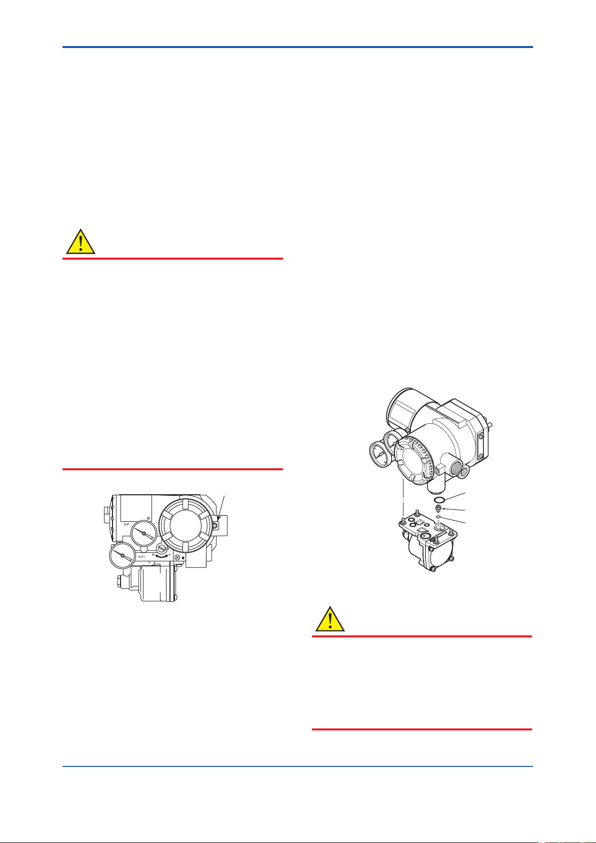
<6. Maintenance>
6. Maintenance
6-1
6.1 General
The modular structure of the YVP110 increases the
ease of maintenance work. This chapter describes
cleaning and part replacement procedures that
should be done for maintenance of the YVP110.
The YVP110 is a precision instrument; read the
following carefully when carrying out maintenance.
For calibrations, see Chapter 5.
CAUTION
Precautions for ATEX ameproof type and
type nA instruments
• Flameproof type and type nA instrumets
must be, as a rule, removed to a nonhazardous area for maintenance and be
disassembled and reassembled to the
original state.
• On the ameproof type and type nA
instruments the terminal cover is locked by
an Allen head bolt (shrouding bolt). When
a shrouding bolt is driven clockwise by an
Allen wrench, it is going in and cover lock is
released, and then the cover can be opened.
When a cover is closed it should be locked
by a shrouding bolt without fail. Tighten the
shrouding bolt to a torque of 0.7 N·m.
6.2 Periodic Inspections
To maintain problem-free plant operation, periodic
inspections are essential. At each periodic
inspection, be especially careful when ensuring
that:
• No external damage can be seen.
• No leakage from the YVP110 or the piping
around it can be detected.
• No build up in the drain, or dust or oil adhering
to the air supply line has occurred.
6.2.1 Cleaning the Fixed Nozzle
The xed nozzle of the YVP110 is attached to the
control relay’s surface that engages the YVP110’s
main structure (see Figure 6.2). Detach the
control relay from the main structure of YVP110 by
following the instruction shown in 6.3.1. Thread a
wire with a 0.25-mm diameter through the nozzle to
clean it. After cleaning the nozzle, place the nozzle
and O-ring at the original position and attach the
control relay again.
Figure 6.1 Shrouding Bolts
Shrouding Bolt
F0601.ai
O-ring
Nozzle
O-ring
F0602.ai
Figure 6.2 Cleaning the Nozzle
CAUTION
All the O-rings used for the sealing of pneumatic
signal circuits are made of silicon rubber. The
sealing capability is degraded if general silicon
grease is applied. When applying grease to a
sealing part, use a type of grease compatible
with silicon rubber, such as uoride grease and
grease for silicon rubber.
IM 21B04C01-01E
Page 40

<6. Maintenance>
6-2
6.3 Part Replacement
6.3.1 Replacing the Control Relay Assembly
(1) Decrease the air supply pressure to zero.
(2) Using a Philips screwdriver, unscrew the four
mounting screws on the bottom face.
(3) Pull the relay assembly downwards to detach it.
(4) To mount a new relay assembly, remove the
mounting screws and washers from the old
assembly and use them to mount the new
assembly in place by tightening them from
below.
(5) When using the Double Acting Type, adjust
the pressure balance of the control relay as
required (in reference to Section 6.3.4).
After completing the replacement of the control
relay assembly, carry out tuning and check the
valve’s actions (in reference to Sections 5.3 and
5.4).
Washer
Mounting screw
6.3.2 Replacing the Screen Filters
When the screen lters installed deep in the air
supply port and output pneumatic signal port
become clogged, replace them with new lters
using a tool with pointed tips such as a set of
tweezers.
Filter
(Only for Double Acting Type.)
If the air supply port at the
back side is used, change
the filter in that port.
Filter
F0604.ai
Figure 6.4 Replacing the Screen Filters
6.3.3 Replacing the Internal Air Filter
An air lter is provided at the opening to the internal
pneumatic circuits. Follow the procedure below to
replace it.
(1) Decrease the air supply pressure to zero.
(2) Remove the relay assembly (in reference with
Section 6.3.1).
(3) Remove the pneumatic circuit holding plate and
gasket*. (*two gaskets for Double Acting Type)
(4) Remove the air lter and O-ring.
(5) Set the new lter in place.
(6) Perform steps (3), then (2) to restore the
YVP110 to its original state.
F0603.ai
Figure 6.3 Replacing the Control Relay Assembly
CAUTION
For the Double Acting Type, the recommended
replacement cycle for the control relay is either
when the actual repeat cycle exceeds 500,000
times, or after the control relay has been in use
for 6 years.
Air filter
O-ring
F0605.ai
Figure 6.5 Replacing the Internal Air Filter
IM 21B04C01-01E
Page 41
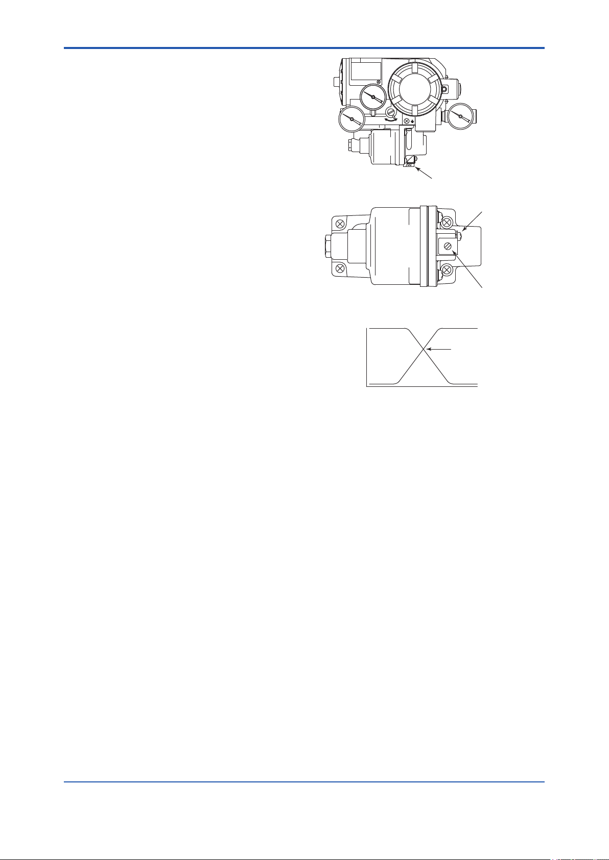
<6. Maintenance>
6.3.4 Tuning the Pressure Balance of Control Relay
When you use a double-acting cylinder actuator,
adjust the pressure balance of the control relay, if
necessary.
The optimal point of pressure balance slightly differs
depending on the packing and load characteristics
of the cylinders used, but in general, approx. 50
to 90% of the supply air pressure is said to be
appropriate.
The pressure balance of the YVP110 is set to
approx. 75% at the time of shipment.
It is possible to reduce the hunting phenomenon
and air consumption by adjusting the balance
pressure.
SUP
A
M
OUT1
Control relay
Do not loosen this screw
6-3
However, if the pneumatic piping is connected to
the valve actuator, the pressure of a cylinder on one
side becomes higher, and the balance cannot be
maintained.
If you want to increase the balance pressure,
turn the screw for adjusting the balance pressure
(shown in Figure 6.6) counterclockwise. If you want
to decrease the balance pressure, turn the screw
clockwise. At this time, you do must not to loosen
the screw beside the adjustment screw.
Pressure balance adjustment screw
100
Output air
pressure
(%)
OUT2
0
OUT1
Pressure balance point
Servo Output
F0606.ai
Figure 6.6 Tuning the Pressure Balance of Control
Relay
IM 21B04C01-01E
Page 42

<7. Standard Specications>
7. Standard Specications
7-1
Standard Specications
Applicable Control Valve:
Linear or Rotary Motion Control Valve
(Diaphragm Actuator and Cylinder)
Functions:
Function Blocks:
AO: One Analog Output
DI: Two Discrete Inputs
OS: One Splitter Block
IS: One Input Selector
AR: One Arithmetic
PID: One or Two PID Control Functions
(Optional)
NOTE
IS, AR and PID (2 blocks) function blocks are
applicable for only software download function
(/EE).
Link Master Function
Pressure Sensor (Optional)
Flow Characterization Feature:
Linear
Equal Percentage (50 : 1)
Equal Percentage (30 : 1)
Quick Opening
Camex Percentage
Customer Characterization (10 segments)
Auto Tuning Function
Valve Position Detecting Function
Contiuous Diagnostics Function:
Total Travel
Number of Cycles
Time Open/Time Close/Time Near Close
Housing Materials:
Case: Aluminum die-cast
Paint: Polyurethane resin-baked nish
Color: Deep-sea moss-green
(Munsell 0.6GY3.l/2.0 or equivalent)
Communication:
Digital: F
OUNDATION eldbus
Supply Voltage:
9 to 32V DC for general use and ameproof
type
9 to 24V DC for intrinsically safe type Entity
model
9 to 17.5V DC for intrinsically safe type FISCO
model
Conditions of Communication Line
Supply Voltage: 9 to 32V DC
Current Draw:
Steady state: 17 mA max.
Software download state: 41 mA max.
Output Signals and Pressure Gauge Scale:
No gauge in standard. Pressure gauge can be
selected as option. The supply pressure unit on
the name plate for non-gauge model is Pa.
Diaphragm, Single acting Cylinder
Calibration
unit
Pa 140 to 400 kPa 400 kPa 400 kPa
kgf/cm
bar 1.4 to 4 bar 4 bar 4 bar
psi 20 to 60 psi 60 psi 60 psi
Calibration
unit
Pa 200 to 700 kPa 1 MPa 1 MPa
kgf/cm
bar 2 to 7 bar 10 bar 10 bar
psi 30 to 105 psi 150 psi 150 psi
Supply Air
Pressure
2
1.4 to 4 kgf/cm24 kgf/cm
Double acting Cylinder
Supply Air
Pressure
2
2 to 7 kgf/cm210 kgf/cm210 kgf/cm
Pressure Gauge Scale
Supply Air Output Signal
2
4 kgf/cm
Pressure Gauge Scale
Supply Air Output Signal
Pressure Gauge Case:
Stainless steel JIS SUS 304
Normal Operating Conditions:
Air Supply pressure:
Single Acting Actuator:
20 to 60 psi (140 to 400 kPa)
Double Acting Actuator:
30 to 100 psi (200 to 700 kPa)
Vibration Limit: 4 mm at 5 to 15 Hz;
2G at 15 to 2000 Hz
Shock limit: 10G
Manual Operation:
Available using Auto/Manual (A/M) transfer
switch
2
2
Zero Adjustment Range:
–15 to 85% of span
IM 21B04C01-01E
Page 43

<7. Standard Specications>
7-2
Span Adjustment Range:
Within 300% of span
Valve-stem Travel Range:
Linear Motion:
10 to 100 mm (0.4 to 4.0 inch)
(Rotation Range: ±10 to ±25 deg)
Rotary Motion:
20 to 90 deg
Air Consumption and Output Capacity:
Diaphragm, Single Acting Cylinder
Maximum Air
Consumption
Maximum Output
Capacity
Maximum Air
Consumption
Maximum Output
Capacity
0.20 SCFM (0.32 Nm
4.1 SCFM (6.6 Nm
Double Acting Cylinder
0.62 SCFM (1.0 Nm
8.5 SCFM (13.7 Nm
3
/h) at 140 kPa
3
/h) at 140 kPa
3
/h) at 400 kPa
3
/h) at 400 kPa
Ambient Temperature Limits:
Single Acting Actuator:
–40 to 85°C (–40 to 185°F)
Double Acting Actuator:
–40 to 60°C (–40 to 140°F) for standard
–10 to 85°C (14 to 185°F) for high
temperature use with option code /HT
Mounting:
Front of Actuator with bracket.
Direct Connection for rotary valve.
Weight:
Single Acting Actuator: 2.4 kg (5.3 lb)
Double Acting Actuator: 2.8 kg (6.2 lb)
Performance Specications
Linearity:
Single Acting Actuator:
±0.5% of Span (including linkages)
Double Acting Actuator:
±1.0% of Span (including linkages)
Hysteresis:
Single Acting Actuator: 0.3% of Span
Double Acting Actuator: 0.5% of Span
Ambient Temperature Effect:
±0.08% of Span/°C
Position Effect:
±0.3% of Span/90 deg
Vibration Effect:
±2% of Span at 2G (15 to 2000 Hz)
Ambient Humidity Limits:
5 to 95% RH at 40°C (104°F)
EMC Conformity Standards:
,
EN61326-1 Class A, Table 2 (For use in
industrial locations)
Degrees of Protection:
IP65, NEMA4X
Connections:
Air Connection: Rc 1/4 or 1/4 NPT female
Electrical Connection: G 1/2, 1/2 NPT, M20 and
Pg13.5 female
Pressure Gauge Connection:
Connections
Codes
Pressure
gauge
connection
1,5
and 6Rc 1/8 female /GP, /GM, and /GB
1/8 NPT
3
female
With pressure
gauge
(Optional)
/GE
IM 21B04C01-01E
Page 44

<7. Standard Specications>
Model and Sufx Codes
Model Sufx Codes Description
YVP110 . . . . . . . . . . . . . . . . . . . . . Valve positioner
Input Signal -F
Applicable Control
Valve
— A
Connections 1
— N
Optional Codes
. . . . . . . . . . . . . . . . . . . Digital communication (FOUNDATION Fieldbus protocol)
. . . . . . . . . . . . . . . . .
1
2 . . . . . . . . . . . . . . . . .
Single Acting Actuator
Double Acting Actuator
. . . . . . . . . . . . . Always A
. . . . . . . . . . .
3 . . . . . . . . . . .
5 . . . . . . . . . . .
6 . . . . . . . . . . .
Electrical Connection: G 1/2, Pneumatic Connection: Rc 1/4
Electrical Connection: 1/2 NPT, Pneumatic Connection: 1/4 NPT
Electrical Connection: DIN Pg 13.5, Pneumatic Connection: Rc 1/4
Electrical Connection: M20, Pneumatic Connection: Rc 1/4
. . . . . . . Always N
/
. . . .
Optional Specications
Optional Specications
Item Description Code
Lightning protection
Coating change Epoxy resin coating X1
Painting
Color change Terminal Cover only
PID function
Output monitor Built-in output pressure sensor *
With pressure gauge
Valve linkage
High temperature use *
Software download
function *
*1: Applicable for Connections code 1, 5 and 6.
*2: Applicable for Connections code 3.
*3: For double acting actuator, OUT1 connection is available.
*4: Single acting actuator type with /BP supports 5 types of signature functions.
*5: Applicable for double acting actuator.
*6: Not applicable for Option code FS15 and KS25.
*7: Applicable for option code EE.
6
Power supply 9 to 32V DC
Allowable current Max. 6000 A(1× 40 μs), repeating 1000 A(1× 40 μs), 100 times
Munsell notation code: N1.5 Black P1
Munsell notation code: 7.5BG4/1.5, jade green P2
Metallic silver P7
PID control function (one block) LC1
PID control function (two blocks) *
Scale and calibration unit: Pa *
Scale and calibration unit: kgf/cm
Scale and calibration unit: bar *
Scale and calibration unit: psi *
7
3
and signature function *
1
2 *1
1
2
4
Two levers: stroke limit of 10 to 100 mm LV1
One lever: stroke limit of 5 to 10 mm
When using this lever set, following performance specications shall be applied;
Linearity:
Single Acting Actuator: ±1.0% of span, Double Acting Actuator: ±2.0% of span
Hysteresis:
Single Acting Actuator: 0.6% of span, Double Acting Actuator: 1.0% of span
5
Ambient temperature limits: –10 to 85°C(14 to 185°F) HT
Based on Foundation Fieldbus Specication(FF-883)
Download class: Class1
7-3
A
LC2
BP
GP
GM
GB
GE
LV2
EE
IM 21B04C01-01E
Page 45

<7. Standard Specications>
Optional Specications (For Explosion Protected types)
Item Description Code
Explosionproof type
Attached ameproof
packing adapter*
4
CSA Explosionproof Approval*
Applicable standard: C22.2 No. 0, No. 0.4, No. 0.5, No. 25, No. 30, No. 94, No. 1010.1
Certicate: 1186507
Explosionproof for Class I, Division 1, Class B, C & D; Class II, Groups E, F & G.,
Class III.
Enclosure Type: NEMA4X Temp. Class: T5/T6
Amb.Temp.: –40 to 82°C(–40 to 180°F) for T5, –40 to 75°C(–40 to 167°F) for T6
FM Explosionproof Approval*
Applicable standard: FM3600, FM3615, FM3810, ANSI/NEMA250
Explosion proof for Class 1, Division 1, Groups A, B, C and D;
Dust-ignitionproof for Class II/III, Division 1, Groups E, F and G
Enclosure Type: NEMA 4X Temp. Class: T6
Amb. Temp.: –40 to 80°C (–40 to 176°F )
FM Intrinsically Safe, Nonincendive Approval*
Applicable standard: FM3600, FM3610, FM3611, FM3810, ANSI/NEMA250
IS/ I, II, III/1/ABCDEFG/T4 Ta=60°C; Type 4X
I/0/AEx ia/IIC/T4 Ta=60°C; Type 4X, NI/I/2/ABCD/T4 Ta=60°C; Type 4X, I/2/IIC/T4
Ta=60°C; Type 4X, S/II/2/FG/T4
Ta=60°C; Type 4X, S/III/2/T4 Ta=60°C; Type 4X
Entity Parameters:
Groups A, B, C, D, E, F, and G and Group IIC Vmax=24 V, Imax=250 mA,
Pi=1.2 W, Ci=1.76 nF, Li=0 mH
FISCO Parameters:
Groups A, B, C, D, E, F, and G and Group IIC Vmax=17.5 V, Imax=360 mA,
Pi=2.52 W, Ci=1.76 nF, Li=0 mH
Groups C, D, E, F, and G and Group IIB Vmax=17.5 V, Imax=380 mA,
Pi=5.32 W, Ci=1.76 nF, Li=0 mH
Nonincendive Field Wiring Parameters:
Groups A, B, C, D, E, F, and G and Group IIC: Vmax=32 V, Ci=1.76 nF, Li=0 mH
FM Nonincendive Approval for /EE Software download *
Applicable standard: FM3600, FM3611, FM3810
Class I, Division 2, Group A, B, C, & D
Class II, Division 2, Group F & G and Class III, Division 1
Class I, Zone 2, Group IIC in Hazardous (Classied) locations
Enclosure: “NEMA4X”, Temp. CI.: T4, Amb. Temp. –40 to 60°C (–40 to 140°F)
Vmax.=32V, Ci=3.52 nF, Li=0μH
ATEX Flameproof Approval*
Applicable standard: EN60079-0:2009, EN60079-1:2007
Certicate: KEMA 10ATEX0023 X
II 2G Ex d IIC T6 or T5 Gb Amb. Temp.: –40 to 65°C (–40 to 149°F) for T6,
–40 to 80°C (–40 to 176°F) for T5
Special fastener: Class A2-50 or more
ATEX Intrinsically Safe Approval*
Applicable standard: EN60079-0:2006, EN60079-11:2007, EN60079-26:2007,
EN60079-27:2006, EN61241-0:2006, EN61241-1:2004, EN61241-11:2006 and
EN60529
Certicate: KEMA 08ATEX0114 X
II 1G Ex ia IIB/IIC T4
II 1D Ex iaD 20 IP65 T100°C
II 1D Ex tD A20 IP65 T100°C
Maximum Surface Temperature for dust proof: T100°C
Ambient Temperature for Ex ia/Ex iaD: –40 to 60°C (–40 to 140°F)
Ambient Temperature for Ex tD: –40 to 80°C (–40 to 176°F)
Enclosure: IP65
For Ex ia IIC or Ex iaD: Ui=24.0 V, Ii=250 mA, Pi=1.2 W, Ci=1.76 nF, Li=0 μH
For Ex ia IIB/ IIC or Ex iaD (FISCO model):
Li=0 μH
For II 1D Ex tD: Input signal: 32 Vdc, Output current: 17 mA
ATEX Intrinsically safe (Ex ic) / Type n (Ex nA)
Applicable standard: EN60079-0:2009/EN60079-0:2012(Ex ic/Ex nA),
EN60079-11:2012(Ex ic), EN60079-15:2010(Ex nA)
Amb. Temp: –30 to 75°C (–22 to 167°F), Enclosure: IP65
Ex ic: II 3G Ex ic IIC T4 Gc (Intrinsically safe) Ui=32 V, Ci=3.52 nF, Li=0 μH
Ex nA: II 3G Ex nA IIC T4 Gc (Non-sparking) 32 V DC MAX.
TIIS Flameproof Approval*
Certicate: TC15453, TC15452 for option code /BP
Ex d IIC T6 Amb. Temp.: –20 to 60°C
Electrical connection: G1/2 female
Applicable cable: O.D. 8 to 12 mm
1
1
1
5
2
2
Ui=17.5 V, Ii=380 mA, Pi=5.32 W, Ci=1.76 nF,
*2 *5
3
7-4
CF1
FF1
FS15
FN15
KF2
KS25
KN25
JF3
G11
IM 21B04C01-01E
Page 46
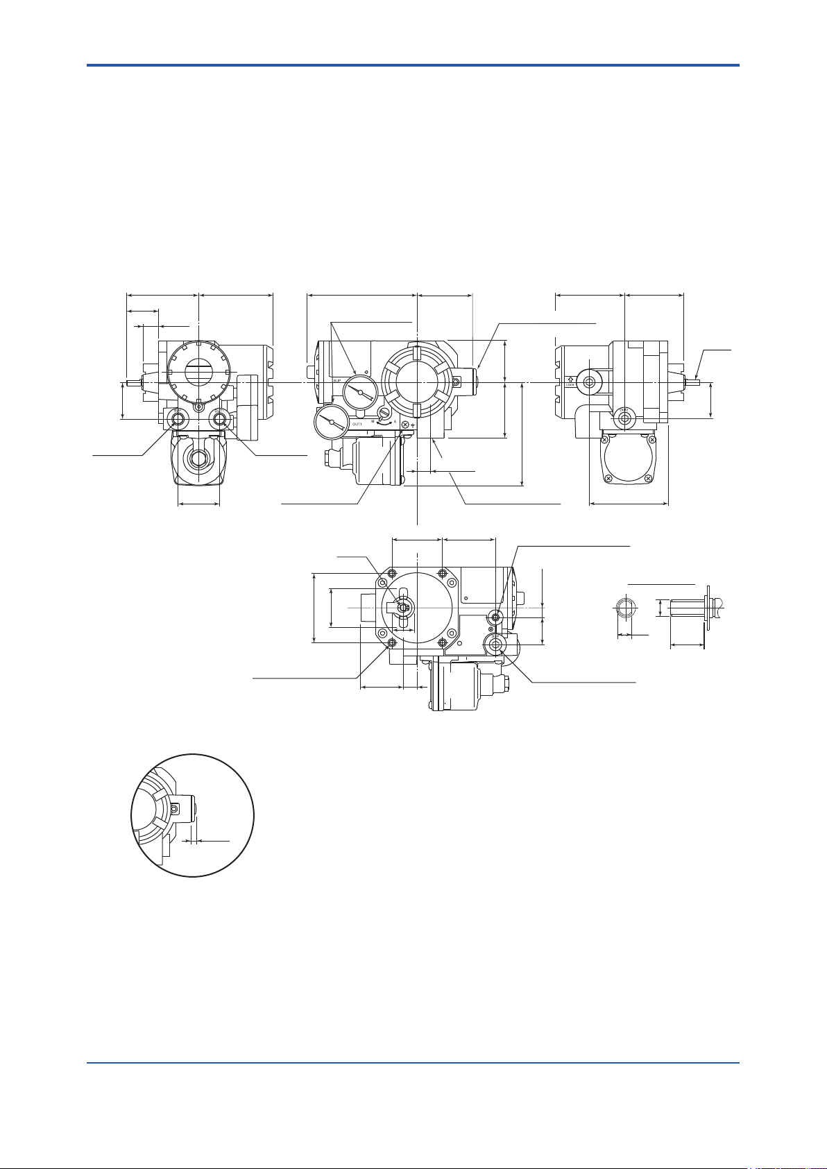
<7. Standard Specications>
*1: Applicable for Connections code 3.
*2: Applicable for Connections code 3 and 6.
*3: Applicable for Connections code 1, 3 and 6.
*4: If cable wiring is to be used to a TIIS ameproof type transmitter, do not fail to add the YOKOGAWA assured ameproof packing
adapter.
*5: Applicable for Option code EE.
Dimensions
l For Single Acting Actuator
Unit: mm(approx. inch)
7-5
39
Air Supply
Connection
77(3.0) 80(3.1)
35
(1.3)
17
(0.7)
(1.5)
44
(1.7)
117(4.6) 76(3.0) 64(2.5)
Pressure Gauge
(Optional)
Out1
Connection
Ground Terminal
Shaft
42
(1.6)
74(2.9)
M8×1.25, 20(0.8)-deep
for Valve Mounting*
2
45
(1.8)
(2.1)
24
15
(0.6)
54
60(2.4)
15(0.6)
Electrical Connection
57
(2.2)
Electrical Connection*
(with blind plug)
45
(1.8)
60(2.4)
109(4.3)
M8×1.25, 11(0.4)-deep
for Valve Mounting*
10(0.4)29
(1.1)
Air Supply Connection
(with blind plug)
1
85(3.3)
3
Details of shaft
ø6
5
12
Shaft
39
(1.5)
*1: Blind plug for Connection code 1, 5, and 6.
5 to 6
(0.2 to 0.24)
*2: Attached with 4 mounting bolts (M8, 25 mm) and spring washers (applicable 3 to 6 mm thick brackets).
*3: Available when unable to mount securely with the 4 bolts in *2.
F0701.ai
IM 21B04C01-01E
Page 47
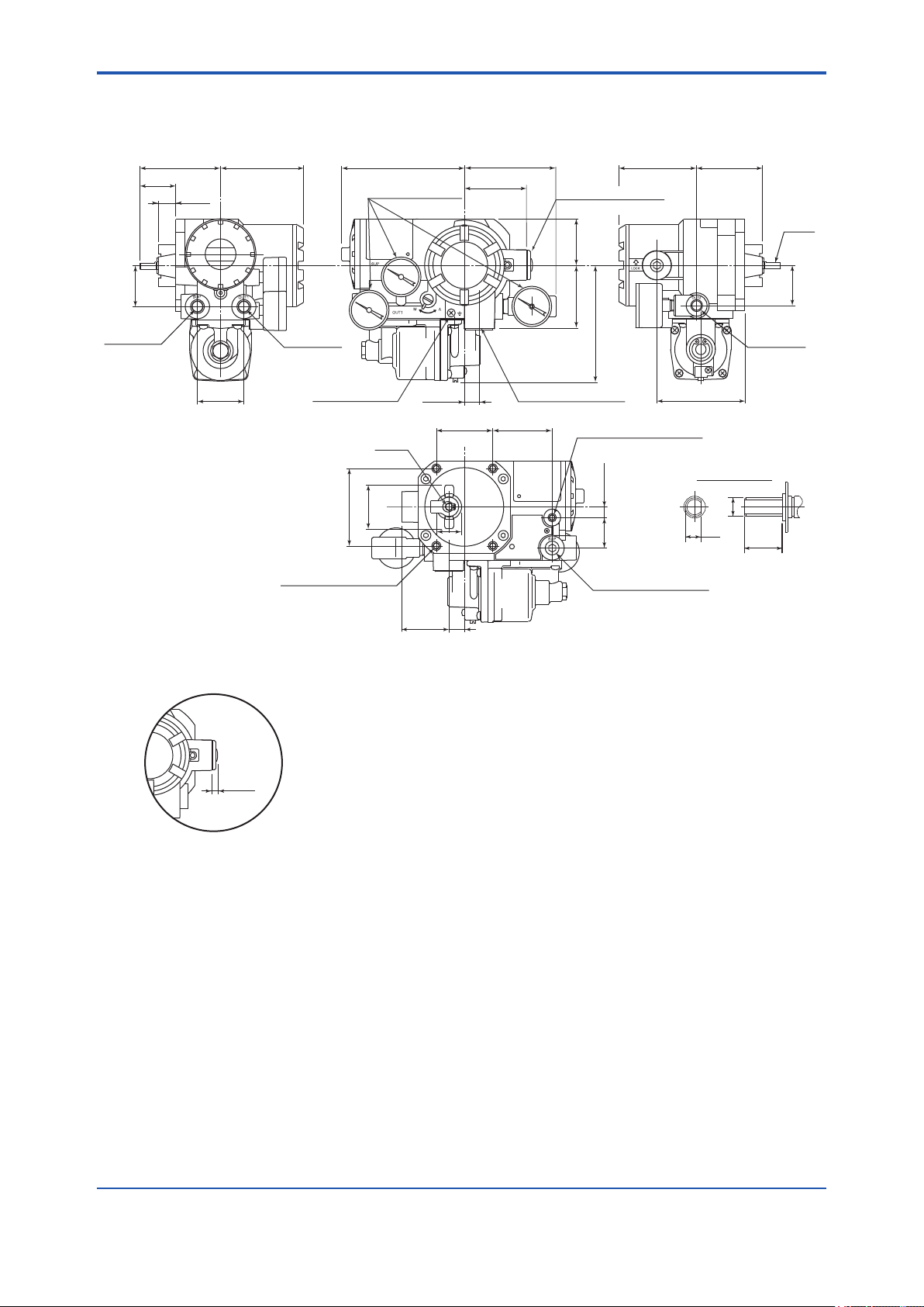
<7. Standard Specications>
l For Double Acting Actuator
Unit: mm(approx. inch)
7-6
(1.3)
39
(1.5)
Air Supply
Connection
77(3.0) 80(3.1)
35
17
(0.7)
44
(1.7)
117(4.6) 76(3.0) 64(2.5)
Out1
Connection
Ground Terminal
Shaft
42
(1.6)
74(2.9)
M8×1.25, 20(0.8)-deep
for Valve Mounting*
2
Pressure Gauge
(Optional)
15(0.6)
24
45
(1.8)
(0.6)
(2.1)
15
54
88(3.5)
60(2.4)
Electrical Connection
57
(2.2)
Electrical Connection*
(with blind plug)
45
(1.8)
60(2.4)
110(4.3)
M8×1.25, 11(0.4)-deep
for Valve Mounting*
10(0.4)29
(1.1)
Air Supply Connection
(with blind plug)
1
85(3.3)
3
Out2
Connection
Details of shaft
ø6
5
12
Shaft
39
(1.5)
*1: Blind plug for Connection code 1, 5, and 6.
5 to 6
(0.2 to 0.24)
*2: Attached with 4 mounting bolts (M8, 25 mm) and spring washers (applicable 3 to 6 mm thick brackets).
*3: Available when unable to mount securely with the 4 bolts in *2.
F0702.ai
IM 21B04C01-01E
Page 48
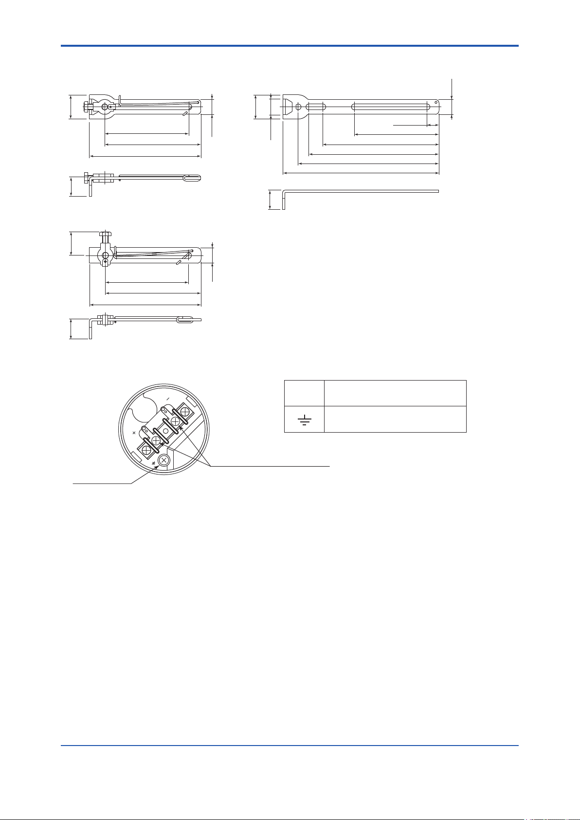
<7. Standard Specications>
Unit: mm(approx. inch)
Lever 1 (Option code /LV1)
26
(1.0)
91(3.6)
104(4.0)
120(4.7)
22
(0.8)
Lever 3 (Option code /LV2)
24
(0.9)
16
(0.6)
Lever 2 (Option code /LV1)
26
(1.0)
17
(0.7)
21
(0.8)
13(0.5)
91(3.6)
125(4.9)
140(5.5)
152(6.0)
168(6.6)
7-7
16
(0.6)
22
(0.8)
Ground terminal
91(3.6)
104(4.0)
120(4.7)
16
(0.6)
Terminal Wiring Terminal Configuration
+
−
Power supply and signal terminal
F0703.ai
Power supply and signal terminal
Ground terminal
F0704.ai
IM 21B04C01-01E
Page 49

<8. About Fieldbus>
8. About Fieldbus
8-1
8.1 Outline
Fieldbus is a bi-directional digital communication
protocol for eld devices, which offers an
advancement in implementation technologies for
process control systems and is widely employed by
numerous eld devices.
YVP110 employs the specication standardized
by The Fieldbus Foundation, and provides
interoperability between Yokogawa devices and
those produced by other manufacturers. Fieldbus
comes with software consisting of AO function
block, two DI function blocks OS function block, IS
function block, AR function block and optional PID
function block, providing the means to implement a
exible instrumentation system.
For information on other features, engineering,
design, construction work, startup and maintenance
of Fieldbus, refer to “Fieldbus Technical Information”
(TI 38K3A01-01E).
8.2 Internal Structure of YVP110
The YVP110 contains two virtual eld devices
(VFD) that share the following functions.
8.2.1 System/network Management VFD
• Sets node addresses and Physical Device tags
(PD Tag) necessary for communication.
• Controls the execution of function blocks.
• Manages operation parameters and
communication resources (Virtual
Communication Relationship: VCR).
8.2.2 Function Block VFD
(1) Resource block
Manages the information common to each FB
VFD in YVP110.
(2) Transducer block
Located between Hardware I/O(actuator,
sensor) and AO/DI function blocks, pass the
control signal from AO function block to I/P
module to control the valve position.
(3) AO function block
• Accepts a control signal from an upstream
block and pass the signal to Transducer
block.
• Accept a valve position signal from
Transducer block and feedback it to an
upstream block.
(4) DI function block
Receives the discrete signal from Transcducer
blcok and output them.
(5) PID function block(optional)
Offers PID control function.
8.3 Logical Structure of Each Block
YVP110
Position SensorI/P Module
Figure 8.1 Logical Structure of Each Block
Setting of various parameters, node addresses,
and PD Tags shown in Figure 8.1 is required before
starting operation.
System/network management VFD
PD tag (Device tag)
Node address
Function Block VFD
Transducer
Position feedback signal
Control output
block
Block tag
Parameters
Resource block
Block tag
Parameters
Communication
parameters
VCR
Function block
execution schedule
AR Function
IS Function
OS Function
PID Function
DI Function
DI Function
AO Function
block
Block tag
Parameters
OUT
Output to other blocksInput from other blocks
F0801.ai
8.4 System Conguration
The following instruments are required for use with
Fieldbus devices:
IM 21B04C01-01E
Page 50

<8. About Fieldbus>
8-2
• Power supply:
Fieldbus requires a dedicated power supply. It
is recommended that current capacity be well
over the total value of the maximum current
consumed by all devices (including the host).
Conventional DC current cannot be used as is.
• Terminator:
Fieldbus requires two terminators. Refer to
the supplier for details of terminators that are
attached to the host.
• Field devices:
Connect the eld devices necessary for
instrumentation. YVP110 has passed the
interoperability test conducted by The Fieldbus
Foundation. In order to properly start Fieldbus,
it is recommended that the devices used satisfy
the requirements of the above test.
• Host:
Used for accessing eld devices. A
dedicated host (such as DCS) is used for
an instrumentation line while dedicated
communication tools are used for experimental
purposes.
• Cable:
Used for connecting devices. Refer to “Fieldbus
Technical Information” (TI 38K3A01-01E) for
details of instrumentation cabling. Provide a
cable sufciently long to connect all devices.
For eld branch cabling, use terminal boards
or a connection box as required. If the total
length of the cable is in a range of 2 to 3 meters
for laboratory or other experimental use, the
following simplied cable (a twisted pair wire
with a cross section of 0.9 mm2 or more (AWG
#18) and cycle period of within 5 cm (2 inches)
may be used. Termination processing depends
on the type of device being deployed. For
YVP110, use an M4 screw terminal claw. Some
hosts require a connector.
Refer to Yokogawa when making arrangements to
purchase the recommended equipment.
The number of devices that can be connected to
a single bus and the cable length vary depending
on system design. When constructing systems,
both the basic and overall design must be carefully
considered to allow device performance to be fully
exhibited.
8.4.1 Connection of Devices
Connect the devices as shown in Figure 9.1.
Connect the terminators at both ends of the
trunk, with a minimum length of the spur laid for
connection.
The polarity of signal and power must be
maintained.
Fieldbus power
supply
Terminator
Figure 8.2 Cabling
YVP110
HOST
Terminator
F0802.ai
Before using a Fieldbus conguration tool other
than the existing host, conrm it does not affect the
loop functionality in which all devices are already
installed in operation. Disconnect the relevant
control loop from the bus if necessary.
8.5 Integration of DD
If the host supports DD (Device Description), the
DD of the YVP110 needs to be installed. Check if
host has the following directory under its default DD
directory.
594543/0001
594543/0007 (/EE)
(594543 is the manufacturer number of
Yokogawa Electric Corporation, and 0001
or 0007 is the YVP110 device number,
respectively.)
If this directory is not found, DD of YVP110 has not
been included. Create the above directory and copy
the DD le (0m0n.ffo,0m0n.sym) (m, n is a numeral)
into the directory.
Once the DD is installed in the directory, the name
and attribute of all parameters of the YVP110 are
displayed.
Off-line conguration is allowed by using the
capability le (CFF). If you do not have the DD or
capability le for the YVP110, you can download it
from www.yokogawa.com/d/
IMPORTANT
For ofine conguration, use the CFF which
matches the specication of the instrument to be
congured. For YVP110, there are three types
of CFF le; one for standard type instruments,
second for the instruments with one or two PID
function blocks are available and the other can
be selected between former two types using
capability level description. Using unmatched
CFF will cause an error upon downloads, etc.
IM 21B04C01-01E
Page 51

<9. Conguration>
9. Conguration
9-1
This chapter contains information on how to adapt
the function and performance of the YVP110 to suit
specic applications. Because two or more devices
are connected to Fieldbus, settings including the
requirements of all devices need to be determined.
Practically, the following steps must be taken.
(1) Network design
Determines the devices to be connected to
Fieldbus and checks the capacity of the power
supply.
(2) Network denition
Determines the tag and node addresses for all
devices.
(3) Denition of combining function blocks
Determines the method for combination
between each function block.
(4) Setting tags and addresses
Sets the PD Tag and node addresses one by
one for each device.
IMPORTANT
Do not turn off the power immediately after
setting. If the power is turned off within 40
seconds after setting is made, the modied
parameters are not saved and the settings return
to the original values.
9.1 Network Design
Select the devices to be connected to the Fieldbus
network. (Refer to 8.4 'System Conguration' for
selection of the devices.)
First, check the capacity of the power supply. The
power supply capacity must be greater than the
sum of the maximum current consumed by all
devices to be connected to Fieldbus. The maximum
current consumed (power supply voltage 9 V to 32
V) for YVP110 is 17 mA. The cable must have the
spur in a minimum length with terminators installed
at both ends of the trunk.
(5) Communication setting
Sets the link between communication
parameters and function blocks.
(6) Block setting
Sets the parameters for function blocks.
The following section describes each step of the
procedure in the order given. Using a dedicated
conguration tool allows the procedure to be
signicantly simplied. This section describes the
procedure to be assigned for a host which has
relatively simple functions. For operation of the
host, refer to the instruction manual for each host.
No details of the host are explained in the rest of
this material.
IMPORTANT
Connecting a Fieldbus conguration tool
to a loop with its existing host may cause
communication data scrambles resulting in a
functional disorder or a system failure.
9.2 Network Denition
Before connection of devices with Fieldbus, dene
the Fieldbus network. Allocate PD Tag and node
addresses to all devices (excluding such passive
devices as terminators).
The PD Tag is the same as the conventional
one used for the device. Up to 32 alphanumeric
characters may be used for denition. Use a
hyphen as a delimiter as required.
The node address is used to specify devices for
communication purposes. Because data is too
long for a PD Tag, the host uses the node address
in place of the PD Tag for communication. A range
of 20 to 247 (or hexadecimal 0x14 to 0xF7) can
be set. Generally, the device (LM device) with bus
control function (Link Master function) is allocated
from a smaller address number (20) side, and other
devices (BASIC device) without bus control function
allocated from a larger address number (247) side
respectively.
IM 21B04C01-01E
Page 52

<9. Conguration>
9-2
Table 9.1 Parameters for Setting Address Range
Symbol Parameters Description
V (FUN) First-Unpolled-
Node
V (NUN) Number-of-
consecutiveUnpolled-Node
Indicates the address
next to the address range
used for the host or other
LM device.
Unused address range.
The devices within the address range written
as “Unused” in Figure 9.1 cannot be used on a
Fieldbus. For other address ranges, the range is
periodically checked to identify when a new device
is mounted. Care must be taken not to allow the
address range to become wider, which can lead to
exhaustive consumption of Fieldbus communication
performance.
0x00
Not used
0x0F
0x10
Bridge device
0x13
0x14
V(FUN)
V(FUN)1V(NUN)
0xF7
0xF8
0xFB
0xFC
0xFF
Figure 9.1 Available Range of Node Addresses
LM device
Unused V(NUN)
BASIC device
Default address
Portable device address
F0901.ai
To ensure stable operation of Fieldbus, determine
the operation parameters and set them to the LM
devices. While the parameters in Table 9.2 are to
be set, the worst-case value of all the devices to
be connected to the same Fieldbus must be used.
Refer to the specication of each device for details.
Table 9.2 lists YVP110 specication values.
Table 9.2 Operation Parameter Values of the
YVP110 to be Set to LM Devices
Symbol Parameters Description and Settings
V (ST) Slot-Time Indicates the time necessary
V (MID) Minimum-
Inter-PDUDelay
V (MRD) Maximum-
Reply-Delay
for immediate reply of the
device. Unit of time is in
octets (256 μs).
Set maximum specication
for all devices. For YVP, set a
value of 4 or greater.
Minimum value of
communication data
intervals. Unit of time is in
octets (256 μs). Set the
maximum specication for all
devices. For YVP, set a value
of 4 or greater.
The worst case time elapsed
until a reply is recorded. The
unit is Slottime; set the value
so that V (MRD) 3V (ST) is
the maximum value of the
specication for all devices.
For YVP, the setting must be
a value of 12 or greater.
9.3 Denition of Combining
Function Blocks
The input/output parameters for function blocks
are combined. Practically, setting is written to the
YVP110 link object with reference to “Block setting”
in Section 9.6 for details.
For the YVP110, in order to minimize the delay in
data transfer between Transducer block and AO
function block, transducer block are designed to
be executed in conjunction with the execution of
AO function block. Therefore, in order to activate
Transducer block, it is necessary that AO function
block is always dened in the schedule.
The combined blocks need to be executed
synchronously with other blocks on the
communications schedule. In this case, change the
YVP110 schedule according to the following table.
Enclosed values in the table are factory-settings.
YVP110 schedule is set as shown in the following.
Change it as necessary.
IM 21B04C01-01E
Page 53

<9. Conguration>
9-3
Table 9.3 Execution Schedule of the YVP110
Function Blocks
Index Parameters
269
(SM)
MACROCYCLE_
DURATION
Setting (Enclosed is
factory-setting)
Cycle (MACROCYCLE)
period of control or
measurement. Unit is 1/32
ms. (32000 = 1 s)
276
(SM)
FB_START_
ENTRY.1
AO block startup time.
Elapsed time from the
start of MACROCYCLE
specied in 1/32 ms.
(32000 = 1 s)
278
(SM)
289
(SM)
FB_START_
ENTRY.2
.
.
.
FB_START_
ENTRY.14
—
—
Table 9.4 shows maximum execution time of YVP
function blocks.
Table 9.4 Execution Time of YVP Function Blocks
Block
Name
Execution
time (ms)
Remarks
AO 95
DI 40
PID 120 Available for option /LC1 or /LC2
OS 95
IS 140 Available for option /EE
AR 120 Available for option /EE
For scheduling of communications for combination
with the next function block, the execution is so
arranged as to start after a lapse of longer than
the time above mentioned. In no case should two
function blocks of the YVP110 be executed at the
same time (execution time is overlapped).
Figure 9.3 shows an example of schedule based on
the loop shown in Figure 9.2.
Macrocycle (Control Period)
EJA110
YVP110
Function
Block
Schedule
Communication
Schedule
AI
OUT
Scheduled Communication
OUT
IN
PID
BKCAL_IN
Unscheduled
Communication
CAS_IN
AO
BKCAL_OUT
F0903.ai
Figure 9.3 Function Block Schedule and
Communication Schedule
For the case where the control period(macrocycle)
is set to 4 seconds or longer, set the following
interval larger than 1% of the macrocycle.
• The interval between 'the end of block
execution' and 'the start of releasing CD from
LAS'.
• The interval between 'the end of a block
execution' and 'the start of the next block
execution'.
9.4 Setting of Tags and Addresses
This section describes the steps in the procedure
to set PD Tags and node addresses in the YVP110.
Connect YVP110 with other network devices and
turn on the power of the host and the bus.
There are three states of Fieldbus devices as
shown in Figure 9.4, and if the state is other than
the lowest SM_OPERATIONAL state, no function
block is executed. YVP110 must be transferred to
this state when a tag or address is changed.
UNINITIALIZED
(No tag nor address is set)
AI
EJA110
Differential Pressure
Transmitter
PID
YVP110
Advanced
Valve Positioner
AO
F902.ai
Figure 9.2 Example of Loop Connecting Function
Block of YVP110 with other instruments
Tag clear Tag setting
INITIALIZED
(Only tag is set)
Address clear
SM_OPERATIONAL
(Tag and address are retained, and
the function block can be executed.)
Address setting
F0904.ai
Figure 9.4 Status Transition by Setting PD Tag and
Node Address
IM 21B04C01-01E
Page 54

<9. Conguration>
9-4
YVP110 has a PD Tag (CV1001) and node
address (247, or hexadecimal 0xF7) that are set
upon shipment from the factory unless otherwise
specied. If two YVP110s are connected at a time,
one YVP110 will keep the address upon shipment
while the other will have a default address(See
Figure 9.2). To change only the node address,
clear the address once and then set a new node
address. To set the PD Tag, rst clear the node
address and clear the PD Tag, then set the PD Tag
and node address again.
Devices whose node address was cleared will
await the default address (randomly chosen from
a range of 248 to 251, or from hexadecimal 0xF8
to 0xFB). At the same time, it is necessary to
specify the device ID in order to correctly specify
the device. The device ID of the YVP110 is
5945430001xxxxxxxx or 5945430007xxxxxxxx.
(The xxxxxxxx at the end of the above device ID is a
total of 8 alphanumeric characters.)
9.5 Communication Setting
To set the communication function, it is necessary
to change the database residing in SM-VFD.
Subscriber (BNU) VCR
A Subscriber receives the data from another
function block(s). This type of communication
is called BNU (Buffered Network-triggered
Unidirectional) VCR.
A Server VCR is capable to respond to requests
from a Client (QUB) VCR after the Client initiates
connection to the Server successfully. A Source
VCR transmits data without established connection.
A Sink (QUU) VCR on another device can receive
it if the Sink is congured so. A Publisher VCR
transmits data when LAS requests so. An explicit
connection is established from Subscriber (BNU)
VCR(s) so that a Subscriber knows the format of
published data.
Parameters must be changed together for each
VCR because modication for each parameter may
cause inconsistent operation.
9.5.2 Function Block Execution Control
According to the instructions given in Section 9.3,
set the execution cycle of the function blocks and
schedule of execution.
9.5.1 VCR Setting
Set VCR (Virtual Communication Relationship),
which species the called party for communication
and resources. YVP110 has 29 or 33 VCRs (with
/EE) whose application can be changed, except for
the rst VCR, which is used for management.
YVP110 has VCRs of four types:
Server(QUB) VCR
A Server responds to requests from a host. This
communication needs data exchange. This
type of communication is called QUB (Queued
User-triggered Bidirectional) VCR.
Source (QUU) VCR
A Source multicasts alarms or trends to other
devices. This type of communication is called
QUU (Queued User-triggered Unidirectional)
VCR.
Publisher (BNU) VCR
A Publisher multicasts AI block output to
another function block(s). This type of
communication is called BNU (Buffered
Network-triggered Unidirectional) VCR.
IM 21B04C01-01E
Page 55

<9. Conguration>
9-5
9.6 Block Setting
Set the parameter for function block VFD.
9.6.1 Link Object
Link object combines the data voluntarily sent
by the function block with VCR. YVP110 has 25
or 50 (with /EE) link objects. A single link object
species one combination. Each link object has the
parameters listed in Table 9.5. Parameters must
be changed together for each VCR because the
modications made to each parameter may cause
inconsistent operation.
Table 9.5 Link Object Parameters
Sub-
index
1 LocalIndex Sets the index of function
2 VcrNumber Sets the index of VCR to be
3 RemoteIndex Sets the index of remote
4 ServiceOperation Set one of the following. Set
5 StaleCountLimit Set the maximum number of
Link objects are not factory-set.
9.6.2 Trend Object
It is possible to set the parameter so that the
function block automatically transmits Trend.
YVP110 has seven or twelve (with /EE) Trend
objects, ve or ten (with /EE) of them are for analog
data, and two of them are for discrete data. A single
Trend object species the trend of one parameter.
Parameters Description
block parameters to be
combined; set “0” for Trend
and Alert.
combined. If set to “0”, this
link object is not used.
object associated with this link
object.
only one each for link object
for Alert or Trend.
0: Undened
1: Local
2: Publisher
6: Alert
7: Trend
consecutive stale input values
which may be received before
the input status is set to BAD.
Setting of "2" or larger value
is recommended to avoid
unnecessary mode transfer
which is caused when
subscriber failed to receive
data correctly.
Table 9.6 Parameters for Trend Objects
Sub-
index
1 Block Index Sets the leading index of the
2 Parameter
3 Sample Type Species how trends are
4 Sample Interval Species sampling intervals
5 Last Update The last sampling time.
6 to 21 List of Status Status part of a sampled
21 to 37 List of Samples Data part of a sampled
Parameters Description
function block that takes a
trend.
Relative Index
Sets the index of parameters
taking a trend by a value
relative to the beginning of
the function block.
taken. Choose one of the
following 2 types:
1: Sampled upon execution
of a function block.
2: The average value is
sampled.
in units of 1/32 ms. Set
the integer multiple of the
function block execution
cycle.
parameter.
parameter.
Objects are not factory-set.
9.6.3 View Object
This is the object to form groups of parameters
in a block. One of advantage brought by forming
groups of parameters is the reduction of load for
data transaction. YVP110 has 12 View objects for
Transducer block and four View objects for each
Resource block, AO block and DI1 and DI2 function
block, and each View object has the parameters
listed in Table 9.8 to 9.15.
Table 9.7 Purpose of Each View Object
Description
VIEW_1 Set of dynamic parameters required by
VIEW_2 Set of static parameters which need to be
VIEW_3 Set of all the dynamic parameters.
VIEW_4 Set of static parameters for conguration or
operator for plant operation. (PV, SV, OUT,
Mode etc.)
shown to plant operator at once. (Range etc.)
maintenance.
Each Trend object has the parameters listed in
Table 9.6. The rst four parameters are the items to
be set.
IM 21B04C01-01E
Page 56

<9. Conguration>
Table 9.8 View Object for Transducer Block
Relative
index
1 ST_REV 2 2 2 2 2 2 2 2 2 2 2 2
2 TAG_DESC
3 STRATEGY 2
4 ALERT_KEY 1
5 MODE_BLK 4 4
6 BLOCK_ERR 2 2
7 UPDATE_EVT
8 BLOCK_ALM
9 TRANSDUCER_
DIRECTORY
10 TRANSDUCER_TYPE 2 2 2 2
11 XD_ERROR 1 1
12 CORRECTION_DIRCTORY
13 FINAL_VALUE 5 5
14 FINAL_VALUE_RANGE 11
15 FINAL_VALUE_CUTOFF_
HI
16 FINAL_VALUE_CUTOFF_
LO
17 FINAL_POSITION_VALUE 5 5
18 SERVO_GAIN 4
19 SERVO_RESET 4
20 SERVO_RATE 4
21 ACT_FAIL_ACTION 1
22 ACT_MAN_ID 4
23 ACT_MODEL_NUM 32
24 ACT_SN 32
25 VALVE_MAN_ID 4
26 VALVE_MODEL_NUM 32
27 VALVE_SN 32
28 VALVE_TYPE 1
29 XD_CAL_LOC 32
30 XD_CAL_DATE 7
31 XD_CAL_WHO 32
32 ALARM_SUM 8 8
33 POSITION_CHAR_TYPE 1
34 POSITION_CHAR
35 LIMSW_HI_LIM 4
36 LIMSW_LO_LIM 4
37 ELECT_TEMP 4 4
38 TEMPERATURE_UNIT 2
39 SUPPLY_PRESSURE 4
40 SPRING_RANGE 11
41 OUT_PRESSURE 4 4
42 SERVO_OUTPUT_SIGNAL 4 4
43 SERVO_RATE_GAIN 4
44 SERVO_DEADBAND 4
45 SERVO_OFFSET 4
46 BOOST_ON_THRESHOLD 8
47 BOOST_OFF_
THRESHOLD
48 BOOST_VALUE 8
49 SERVO_I_SLEEP_LMT 4
50 SERVO_P_ALPHA 4
Parameters
VIEW 1VIEW 2VIEW
3 1st
VIEW
3 2nd
VIEW
4 1st
4
4
VIEW
4 2nd
VIEW
4 3rd
8
VIEW
4 4th
VIEW
4 5th
VIEW
4 6th
VIEW
4 7th
9-6
VIEW
4 8th
IM 21B04C01-01E
Page 57

<9. Conguration>
9-7
Relative
index
51 INTERNAL_GAIN 4
52 MEAS_GAIN 4
53 VALVE_TC 4
54 VALVE_HYS 4
55 VALVE_SLIP_WIDTH 4
56 MEAS_PRESS_AIR 4
57 MEAS_PRESS_SUPPLY 4
58 MEAS_SPRING_RANGE 8
59 CONTROL_DIR 1
60 THETA_HI 4
61 THETA_LO 4
62 THETA_P 4
63 TRAVEL_CALIB_EXEC 1
64 TRAVEL_CALIB_RESULT 1
65 OPEN_STOP_ADJ 4
66 AUTO_TUNE_EXEC 1
67 AUTO_TUNE_RESULT 1
68 AUTO_TUNE_STATE 1
69 SERVO_RET_TO_
DEFAULT
70 ADVAL_FW 2
71 ADVAL_BW 2
72 ADVAL_PRESS 2
73 ADVAL_T 2
74 TOTAL_CYCLE_COUNT 4
75 CYCLE_DEADBAND 4
76 CYCLE_COUNT_LIM 4
77 TOTAL_TRAVEL 4
78 TRAVEL_DEADBAND 4
79 TRAVEL_LIM 4
80 TOTAL_OPEN_TIME 4
81 TOTAL_CLOSE_TIME 4
82 OPEN_CLOSE_
THRESHOLD
83 OPEN_TIME_LIM 4
84 CLOSE_TIME_LIM 4
85 TOTAL_NEAR_CLOSE_
TIM
86 NEAR_CLOSE_
THRESHOLD
87 NEAR_CLOSE_TIME_LIM 4
88 DEVIATION_LIM 4
89 DEVIATION_TIME_TH 8
90 RELEASE_FAILSAFE 1
91 MODEL 32
92 DEV_OPTIONS 2
93 PRESS_SENS_INSTALLED 1
94 ACTUATOR_TYPE 1
95 RELAY_TYPE 1
96 SIGN_MEAS_EXEC 1
97 SIGN_MEAS_RESULT 1
98 SIGN_MEAS_STATE 1
99 SIGN_MEAS_COUNTER 2
100 SIGN_DATA_SAVE 1
Parameters
VIEW 1VIEW 2VIEW
3 1st
1
4
VIEW
3 2nd
VIEW
4 1st
VIEW
4 2nd
VIEW
4 3rd
VIEW
4 4th
4
4
VIEW
4 5th
VIEW
4 6th
VIEW
4 7th
VIEW
4 8th
IM 21B04C01-01E
Page 58

<9. Conguration>
9-8
Relative
index
Parameters
101 SIGN_UPLOAD_
DATABASE
VIEW 1VIEW 2VIEW
3 1st
VIEW
3 2nd
VIEW
4 1st
VIEW
4 2nd
VIEW
4 3rd
VIEW
4 4th
VIEW
4 5th
1
VIEW
4 6th
VIEW
4 7th
102 SIGN_UPLOAD_POINTER 2
103 SIGN_DATA_X
104 SIGN_DATA_Y
105 SIGN_MEAS_DATE 7
106 SIGN_HEADER_DATA 28
107 STD_ACT_SIGN_SET 12
108 EXT_ACT_SIGN_SET 24
109 STEP_RESP_SET 16
110 POSITIONER_SIGN_SET 20
111 SERVO_WARN_HI_LIM 4
112 SERVO_WARN_LO_LIM 4
113 SERVO_TIME_TH 4
114 SERVO_WARN_COUNT 4
115 X_BST_ON_THRESHOLD 8
116 X_BST_OFF_THRESHOLD 8
117 X_BOOST_VALUE 8
118 to
165
TEST_1 to
TEST_47 *
1
14 69 87 76
Total (in bytes) 41 59 99 104 96 95 97 103 95 89 90 26
*1: These parameters are not usually used.
“TEST_48 (Relative index 165)” applies to option code EE.
VIEW
4 8th
Table 9.9 View Object for AO Function Block
Relative
index
Parameters
VIEW 1VIEW 2VIEW 3VIEW
1 ST_REV 2 2 2 2
2 TAG_DESC
3 STRATEGY 2
4 ALERT_KEY 1
5 MODE_BLK 4 4
6 BLOCK_ERR 2 2
7 PV 5 5
8 SP 5 5
9 OUT 5 5
10 SIMULATE
11 PV_SCALE 11
12 XD_SCALE 11
13 GRANT_DENY 2
14 IO_OPTS 2
15 STATUS_OPTS 2
16 READBACK 5 5
4
index
Relative
Parameters
VIEW 1VIEW 2VIEW 3VIEW
4
17 CAS_IN 5 5
18 SP_RATE_DN 4
19 SP_RATE_UP 4
20 SP_HI_LIM 4
21 SP_LO_LIM 4
22 CHANNEL 2
23 FSAFE_TIME 4
24 FSAFE_VAL 4
25 BKCAL_OUT 5
26 RCAS_IN 5
27 SHED_OPT 1
28 RCAS_OUT 5
29 UPDATE_EVT
30 BLOCK_ALM
Total (in bytes) 33 34 48 28
IM 21B04C01-01E
Page 59

<9. Conguration>
9-9
Table 9.10 View Object for DI1, DI2 Function Block
Relative
index
1 ST_REV 2 2 2 2
2 TAG_DESC
3 STRATEGY 2
4 ALERT_KEY 1
5 MODE_BLK 4 4
6 BLOCK_ERR 2 2
7 PV_D 2 2
8 OUT_D 2 2
9 SIMULATE_D
10 XD_STATE 2
11 OUT_STATE 2
12 GRANT_DENY 2
13 IO_OPTS 2
14 STATUS_OPTS 2
15 CHANNEL 2
16 PV_FTIME 4
17 FIELD_VAL_D 2 2
18 UPDATE_EVT
19 BLOCK_ALM
20 ALARM_SUM 8 8
21 ACK_OPTION 2
22 DISC_PRI 1
23 DISC_LIM 1
24 DISC_ALM
Parameters
VIEW 1VIEW 2VIEW 3VIEW
4
Table 9.11 View Object for OS Function Block
Relative
index
1 ST_REV 2 2 2 2
2 TAG_DESC
3 STRATEGY 2
4 ALERT_KEY 1
5 MODE_BLK 4 4
6 BLOCK_ERR 2 2
7 SP 5 5
8 OUT_1 5 5
9 OUT_2 5 5
10 OUT_1_RANGE 11
11 OUT_2_RANGE 11
12 GRANT_DENY 2
13 STATUS_OPTS 2
14 CAS_IN 5 5
15 BKCAL_OUT 5
16 IN_ARRAY 16
17 OUT_ARRAY 16
18 LOCKVAL 1
19 BKCAL_IN_1 5
20 BKCAL_IN_2 5
21 BAL_TIME 4
22 HYSTVAL 4
23 UPDATE_EVT
24 BLOCK_ALM
Parameters
VIEW 1VIEW 2VIEW 3VIEW
4
Total (in bytes) 22 8 22 19
Total (in bytes) 28 26 43 48
IM 21B04C01-01E
Page 60

<9. Conguration>
9-10
Table 9.12 View Object for IS Function Block
Relative
index
1 ST_REV 2 2 2 2
2 TAG_DESC
3 STRATEGY 2
4 ALERT_KEY 1
5 MODE_BLK 4 4
6 BLOCK_ERR 2 2
7 OUT 5 5
8 OUT_RANGE 11
9 GRANT_DENY 2
10 STATUS_OPTS 2
11 IN_1 5 5
12 IN_2 5 5
13 IN_3 5 5
14 IN_4 5 5
15 DISABLE_1 2 2
16 DISABLE_2 2 2
17 DISABLE_3 2 2
18 DISABLE_4 2 2
19 SELECT_TYPE 1
20 MIN_GOOD 1
21 SELECTED 2 2
22 OP_SELECT 2 2
23 UPDATE_EVT
24 BLOCK_ALM
25 IN_5 5 5
26 IN_6 5 5
27 IN_7 5 5
28 IN_8 5 5
29 DISABLE_5 2 2
30 DISABLE_6 2 2
31 DISABLE_7 2 2
32 DISABLE_8 2 2
Parameters
Total (in bytes) 73 15 73 9
VIEW 1VIEW 2VIEW 3VIEW
Table 9.13 View Objects of AR Function Block
4
Relative
index
1 ST_REV 2 2 2 2
2 TAG_DESC
3 STRATEGY 2
4 ALERT_KEY 1
5 MODE_BLK 4 4
6 BLOCK_ERR 2 2
7 PV 5 5
8 OUT 5 5
9 PRE_OUT 5 5
10 PV_SCALE 11
11 OUT_RANGE 11
12 GRANT_DENY 2
13 INPUT_OPTS 2
14 IN 5
15 IN_LO 5
16 IN_1 5
17 IN_2 5
18 IN_3 5
19 RANGE_HI 4
20 RANGE_LO 4
21 BIAS_IN_1 4
22 GAIN_IN_1 4
23 BIAS_IN_2 4
24 GAIN_IN_2 4
25 BIAS_IN_3 4
26 GAIN_IN_3 4
27 COMP_HI_LIM 4
28 CONP_LO_LIM 4
29 ARITH_TYPE 1
30 BAL_TIME 4
31 BIAS 4
32 GAIN 4
33 OUT_HI_LIM 4
34 OUT_LO_LIM 4
35 UPDATE_EVT
36 BLOCK_ALM
Parameters
VIEW 1VIEW 2VIEW 3VIEW
4
Total (in bytes) 23 26 48 68
IM 21B04C01-01E
Page 61

<9. Conguration>
Table 9.14 View Object for PID Function Block
Relative
index
1 ST_REV 2 2 2 2
2 TAG_DESC
3 STRATEGY 2
4 ALERT_KEY 1
5 MODE_BLK 4 4
6 BLOCK_ERR 2 2
7 PV 5 5
8 SP 5 5
9 OUT 5 5
10 PV_SCALE 11
11 OUT_SCALE 11
12 GRANT_DENY 2
13 CONTROL_OPTS 2
14 STATUS_OPTS 2
15 IN 5
16 PV_FTIME 4
17 BYPASS 1
18 CAS_IN 5 5
19 SP_RATE_DN 4
20 SP_RATE_UP 4
21 SP_HI_LIM 4
22 SP_LO_LIM 4
23 GAIN 4
24 RESET 4
25 BAL_TIME 4
26 RATE 4
27 BKCAL_IN 5
28 OUT_HI_LIM 4
29 OUT_LO_LIM 4
30 BKCAL_HYS 4
31 BKCAL_OUT 5
32 RCAS_IN 5
33 ROUT_IN 5
34 SHED_OPT 1
35 RCAS_OUT 5
Parameters
VIEW 1VIEW 2VIEW 3VIEW
4
Relative
index
36 ROUT_OUT 5
37 TRK_SCALE 11
38 TRK_IN_D 2 2
39 TRK_VAL 5 5
40 FF_VAL 5
41 FF_SCALE 11
42 FF_GAIN 4
43 UPDATE_EVT
44 BLOCK_ALM
45 RM_SUM 8 8
46 ACK_OPTION 2
47 ALARM_HYS 4
48 HI_HI_PRI 1
49 HI_HI_LIM 4
50 HI_PRI 1
51 HI_LIM 4
52 LO_PRI 1
53 LO_LIM 4
54 LO_LO_PRI 1
55 LO_LO_LIM 4
56 DV_HI_PRI 1
57 DV_HI_LIM 4
58 DV_LO_PRI 1
59 DV_LO_LIM 4
60 HI_HI_ALM
61 HI_ALM
62 LO_ALM
63 LO_LO_ALM
64 DV_HI_ALM
65 DV_LO_ALM
Parameters
Total (in bytes) 43 43 83 104
VIEW 1VIEW 2VIEW 3VIEW
9-11
4
IM 21B04C01-01E
Page 62

<9. Conguration>
9-12
Table 9.15 View Object for Resource Block
Relative
index
1 ST_REV 2 2 2 2
2 TAG_DESC
3 STRATEGY 2
4 ALERT_KEY 1
5 MODE_BLK 4 4
6 BLOCK_ERR 2 2
7 RS_STATE 1 1
8 TEST_RW
9 DD_RESOURCE
10 MANUFAC_ID 4
11 DEV_TYPE 2
12 DEV_REV 1
13 DD_REV 1
14 GRANT_DENY 2
15 HARD_TYPES 2
16 RESTART
17 FEATURES 2
18 FEATURE_SEL 2
19 CYCLE_TYPE 2
20 CYCLE_SEL 2
21 MIN_CYCLE_T 4
22 MEMORY_SIZE 2
23 NV_CYCLE_T 4
24 FREE_SPACE 4
25 FREE_TIME 4 4
26 SHED_RCAS 4
27 SHED_ROUT 4
28 FAULT_STATE 1 1
29 SET_FSTATE
30 CLR_FSTATE
31 MAX_NOTIFY 1
32 LIM_NOTIFY 1
33 CONFIRM_TIME 4
34 WRITE_LOCK 1
35 UPDATE_EVT
36 BLOCK_ALM
37 ALARM_SUM 8 8
38 ACK_OPTION 2
39 WRITE_PRI 1
40 WRITE_ALM
41 ITK_VER 2
42 SOFT_REV
43 SOFT_DESC
44 SIM_ENABLE_MSG
45 DEVICE_STATUS_1 4 2
46 DEVICE_STATUS_2 4
47 DEVICE_STATUS_3 4 2
48 DEVICE_STATUS_4 4 1
49 DEVICE_STATUS_5 4
50 DEVICE_STATUS_6 4
51 DEVICE_STATUS_7 4
52 DEVICE_STATUS_8 4
Parameters
VIEW 1VIEW 2VIEW 3VIEW
Table 9.16 Indexes of View for Each Block
4
Resourse Block 40100 40101 40102 40103
Transducer Block
AO Function Block 40500 40501 40502 40503
DI1 Function Block 40600 40601 40602 40603
DI2 Function Block 40610 40611 40612 40613
PID or PID1 (with
/EE) Function Block
PID2 Function
Block
OS Function Block 41400 41401 41402 41403
IS Function Block 41700 41701 41702 41703
AR Function Block 41750 41751 41752 41753
VIEW_1 VIEW_2 VIEW_3 VIEW_4
40200 40201
40800 40801 40802 40803
40810 40811 40812 40813
40202,
40203
40204
through
40211
9.6.4 Function Block Parameters
Function block parameters can be read from the
host or can be set. For a list and details of the
parameters of blocks held by the YVP110, refer to
the chapter for each function block and the list of
parameters in the latter part of this manual.
Total (in bytes) 22 30 54 31
IM 21B04C01-01E
Page 63

<10. Actions of YVP110 During Operation>
10-1
10. Actions of YVP110 During Operation
10.1 Block Modes
All function blocks have modes. All blocks have
their mode, expressed by MODE_BLK parameter.
It is a structure of four components; Target,
Actual, Permitted and Normal. Target is the mode
into which an operator wants to bring this block.
This component is writable. Actual shows the
actual mode of the block and is read-only. When
necessary condition is satised, actual mode
becomes same to target. There is a chance that
actual mode says different from target by some
reason. Permitted mode shows which mode is
allowed in this Function Block. Normal mode is a
memo for operator to record mode that an operator
expects in normal conditions.
The table below shows the modes supported by
each function block contained in a YVP110.
Table 10.1 Block Modes
Function Block Modes
Resource Auto, O/S
Transducer Auto, O/S
AO RCas, Cas, Auto, Man, (LO), (IMan),
O/S
DI Auto, Man, O/S
OS Auto, Cas, (IMan), O/S
PID Rout, RCas, Cas, Auto, Man, (LO),
(IMan), O/S
IS Auto, Man, O/S
AR Auto, Man, O/S
Modes marked with ( ) in the above table cannot be
specied as “target”.
LO mode
Means Local Override mode. If the PID block
enters LO mode, the block output follows the
tracking value (TRK_VAL). In AO block, the block
enters LO mode when the block detects the fault
status. In this case, the block holds the output or
outputs the pre-congured value (FSTATE_VALUE)
according to the setting of options.
Man mode
Means Manual mode. If the data status of a
function block’s input is bad or its target mode is
Man, the block enters Man mode. In Man mode,
the function block does not update its OUT value.
If the target is also Man, it allows the user to write a
desired value to it.
Auto mode
In Auto mode, the function block performs the
specied calculations based on the setpoint
and outputs the result, independently without
interlocking with another function block. The user
can write the setpoint of a function block in this
mode if the target is Auto. If the target mode of
a function block is Auto, or if both of the following
conditions are met for a function bock, the block
enters Auto mode:
• The target mode is Cas or RCas.
• There is an error in communication with the
upstream function block.
Cas mode
The following are outlines of each mode.
O/S mode
Means Out of Service mode, in which the block
does not run, and its output and setpoint maintain
their previous values.
IMan mode
Means Initialization Manual mode. Only the AO and
PID blocks in the YVP110 support this mode. When
one of these blocks detects a loss of a correct
path to the downstream block (such as when the
downstream block is in the O/S, Man, Auto or LO
mode), it enters IMan mode. For example, when
the data status of BKCAL_IN in a PID block is “bad”
or “good: not invited”, the PID block enters IMan
mode.
Means Cascade mode. In Cas mode, the function
block performs the specied calculations based on
the setpoint that is input from a different function
block via the cascade input parameter and outputs
the result.
ROut mode
Means Remote Output mode. In ROut mode, the
output of the function block is set to the value of the
remote output parameter that is written by a host
computer or others. To prevent a sudden change in
output, the block’s calculations are initialized when
a change in mode occurs.
IM 21B04C01-01E
Page 64

<10. Actions of YVP110 During Operation>
10-2
RCas mode
Means Remote Cascade mode. In RCas
mode, the function block performs the specied
calculations based on the setpoint that is input from
host computer or others via the remote cascade
parameter, and outputs the result.
Table 10.2 Examples of Block Mode Combinations
and Operation Statuses
Operation Statuses AI PID AO TB
Transducer Initial
setup, valve setup
(when carrying out
auto tuning, travel
calibration, etc.)
Modication of
parameter settings
in transducer block
(modication of
control parameter
settings, etc.)
Constant valve
position control
PID single-loop
control
PID cascade-loop
control
— — O/S O/S
— — O/S O/S
— — Auto Auto
Auto Auto Cas Auto
Auto Primary PID:
Auto
Secondary PID:
Cas
Cas Auto
10.2 Alarm Generation
When the YVP110 detects an abnormality in the
device itself by the self-diagnostic function, a device
alarm is issued from the resource or transducer
block. An abnormality in a function block or in a
process value is issued from the corresponding
block as a block error or process alarm.
A YVP110 can report the following alarms and
events.
Analog alerts: A type of alarm generated when
a process value or a deviation value exceeds a
specied limit in the following blocks:
PID block : HI, HI_HI, LO, LO_LO, DV_HI, DV_LO
Discrete alerts: A type of alarm generated when
an abnormal status is detected. For the resource
block, a discrete alert is generated as a block alarm
or write-error alarm. For the DI block, a discrete
alert is generated as a block alarm or DISC alarm.
For the Transducer block, AO, OS, IS, AR block and
PID block, a discrete alert is only generated as a
block alarm.
Update alerts: Generated whenever a change is
made to the settings of the certain parameters.
Table 10.2 shows examples of block mode
combinations in a YVP110 (however, it does not
show all patterns). When a block changes mode
or the data status of a signal changes for some
reason, the other blocks connected to that block
identify the change by detecting the change in
status of an input signal, and change their modes,
too. For example, when the data status of BKCAL_
IN in a PID block changes to bad, the PID block
automatically change mode to IMan to initialize the
control of its downstream block.
The respective modes to which each block should
enter upon occurrence of a communication error
and at a restart, and the handling of signals in
each mode may be dened in the block’s option
parameters such as IO_OPTS and STATUS_
OPTS. For details, see the detailed descriptions of
each function block.
Table 10.3 shows the elements composing an alert
object.
IM 21B04C01-01E
Page 65

<10. Actions of YVP110 During Operation>
10-3
Table 10.3 Alert Objects
Subindex
Parameter
Name
Analog Alert
Discrete Alert
Update Alert
1 1 1
2 2 2 Alert Key Copy of ALERT_KEY
3 3 3
4 4 4
5 5 5
6 6 6 Priority Priority level of the alert
7 7 7
8 8
9 9 Value Value of the related data
10 10
11 11 9 Unit Index Unit code of the related data
Block Index Leading Index to the block in
Standard
Type
Mfr Type The name of the alert dened
Message
Type
Time Stamp Time when the alert occurred
Subcode Subcode that indicates the
Relative
Index
Static
8
Revision
which the alert has occurred
Type of the alert that occurred
in the device description
(DD) le written by the device
manufacturer.
Cause of the alert
rst
cause of the alert
Relative Index to the related
data
Value of ST_REV in the block
Description
10.3 Simulation Function
The YVP110 has a function to simulate input
signals to its internal function blocks and makes the
blocks to carry out the specied actions with the
simulated input signals in order to allow for testing
applications in the host computer or alarm handling
processes. Each function block has a parameter
to switch on/off the simulation function. To prevent
this parameter setting from being modied during
plant operation by mistake, a hardware switch
labeled SIM.ENABLE is provided on the YVP110’s
amplier assembly. Sliding this switch position
to ON enables the simulation function to run.
Remotely writing “REMOTE LOOP TEST SWITCH”
to SIM_ENABLE_MSG also causes the same
effect as turning ON the SIM.ENABLE switch;
however, the value of SIM_ENABLE_MSG will
be lost when the power to the YVP110 is turned
off. In short, simulation can be carried out if the
hardware SIM.ENABLE switch is ON or if the value
of SIM_ENABLE_MSG is “REMOTE LOOP TEST
SWITCH”.
When the simulation can be carried out, alarms
generated from the resource blocks mask the other
device alarms. Hence, simulation must be disabled
immediately after it has nished.
SIM.ENABLE switch
Normally OFF
Unused
Figure 10.1 SIM.ENABLE Switch
1
2
O
N
F1001.ai
IM 21B04C01-01E
Page 66

<11. Resource Block>
11. Resource Block
11-1
11.1 General
The resource block stores device hardware
information related to all function blocks in the same
device, such as the memory size, and controls
the device hardware and internal function blocks.
Regardless of the execution schedule of the
function blocks, the resource block runs at a certain
interval.
11.2 Alarm Processing
The resource block generates a block alarm in the
following cases:
• An error represented by a bit in BLOCK_
ERROR, shown in the table below, has
occurred (identied as a Block alarm).
• A static parameter has been written (identied
as an update event).
• The value of a write-locked parameter has been
modied (identied as Write alarm).
Table 11.1 BLOCK_ERROR in Resource Block
Bit
Name of Error
Represented
3 Simulate Active SIMULATE is active.
5 Device Fail Safe Set Fail safe function is set.
10 Lost Static Data
11 Lost NV Data
13 Device Needs
Needs servicing urgently.
Maintenance Now
15 Out-of-Service The target mode is O/S.
Cause
11.3 Device Status
When fault occurs, the corresponding bits in the
parameters DEVICE_STATUS_1 to _3 of the
resource block are set on. Table 11.2 to 11.4 show
the codes and indication corresponding to the
individual bits in DEVICE_STATUS_1 to _3 as well
as the meanings represented.
Table 11.2 DEVICE_STATUS_1 (without /EE)
Indication
Hexadecimal
Indication
0x80000000
0x40000000
0x20000000
0x10000000
0x08000000
0x04000000
0x02000000
0x01000000
0x00800000 Sim.enable
0x00400000 RB in O/S
0x00200000
0x00100000
0x00080000 EEPROM
0x00040000
0x00020000
0x00010000
0x00008000 Link Obj.1/17
0x00004000 Link Obj.2/18
0x00002000 Link Obj.3/19
0x00001000 Link Obj.4/20
0x00000800 Link Obj.5/21
0x00000400 Link Obj.6 /22
0x00000200 Link Obj.7/23
0x00000100 Link Obj.8/24
when Device
Description is
installed.
Jmpr On
mode
Failure
not open
not open
not open
not open
not open
not open
not open
not open
Meaning
The SIM.ENABLE switch on the
amplier is set to ON.
The Resource block is in O/S
mode.
EEPROM failure
1
The VCR*
or 17 is specied to be linked is
not open.
The VCR*
or 18 is specied to be linked is
not open.
The VCR*
or 19 is specied to be linked is
not open.
The VCR*
or 20 is specied to be linked is
not open.
The VCR*
or 21 is specied to be linked is
not open.
The VCR*
or 22 is specied to be linked is
not open.
The VCR*
or 23 is specied to be linked is
not open.
The VCR*
or 24 is specied to be linked is
not open.
to which link object 1
1
to which link object 2
1
to which link object 3
1
to which link object 4
1
to which link object 5
1
to which link object 6
1
to which link object 7
1
to which link object 8
IM 21B04C01-01E
Page 67

<11. Resource Block>
11-2
Indication
Hexadecimal
Indication
when Device
Description is
Meaning
installed.
1
0x00000080 Link Obj.9/25
not open
The VCR*
or 25 is specied to be linked is
to which link object 9
not open.
1
0x00000040 Link Obj.10
not open
The VCR*
10 is specied to be linked is not
to which link object
open.
1
0x00000020 Link Obj.11
not open
The VCR*
11 is specied to be linked is not
to which link object
open.
1
0x00000010 Link Obj.12
not open
The VCR*
12 is specied to be linked is not
to which link object
open.
1
0x00000008 Link Obj.13
not open
The VCR*
13 is specied to be linked is not
to which link object
open.
1
0x00000004 Link Obj.14
not open
The VCR*
14 is specied to be linked is not
to which link object
open.
1
0x00000002 Link Obj.15
not open
The VCR*
15 is specied to be linked is not
to which link object
open.
1
0x00000001 Link Obj.16
not open
The VCR*
16 is specied to be linked is not
to which link object
open.
*1: VCR: Virtual Coummunications Relationship
Table 11.3 DEVICE_STATUS_1 (with /EE)
Indication
Hexadecimal
Indication
0x80000000
0x40000000
0x20000000
0x10000000
0x08000000
0x04000000 Abnormal
0x02000000 Download fail Download fail
0x01000000 Download
0x00800000 Sim.enable
0x00400000 RB in O/S
0x00200000
0x00100000
0x00080000 EEPROM
0x00040000
0x00020000
0x00010000
0x00008000 Link
0x00004000 Link
0x00002000 Link
0x00001000 Link
0x00000800 Link
0x00000400 Link Obj.6
0x00000200 Link
0x00000100 Link
0x00000080 Link
0x00000040 Link
0x00000020 Link
0x00000010 Link
when Device
Description is
installed.
Boot Process
incomplete
Jmpr On
mode
Failure
Obj.1/17/33/49
not open
Obj.2/18/34/50
not open
Obj.3/19/35
not open
Obj.4/20/36
not open
Obj.5/21/37
not open
/22/38
not open
Obj.7/23/39
not open
Obj.8/24/40
not open
Obj.9/25/41
not open
Obj.10/26/42
not open
Obj.11/27/43
not open
Obj.12/28/44
not open
Meaning
Abnormal boot process
Download incomplete
The SIM.ENABLE switch on the
amplier is set to ON.
The Resource block is in O/S
mode.
EEPROM failure
1
The VCR*
to which link object
1, 17, 33 or 49 is specied to be
linked is not open.
1
The VCR*
to which link object
2, 18, 34 or 50 is specied to be
linked is not open.
1
The VCR*
to which link object 3,
19, or 35 is specied to be linked
is not open.
1
The VCR*
to which link object 4,
20, or 36 is specied to be linked
is not open.
1
The VCR*
to which link object 5,
21, or 37 is specied to be linked
is not open.
1
The VCR*
to which link object 6,
22, or 38 is specied to be linked
is not open.
1
The VCR*
to which link object 7,
23, or 39 is specied to be linked
is not open.
1
The VCR*
to which link object 8,
24, or 40 is specied to be linked
is not open.
1
The VCR*
to which link object 9,
25, or 41 is specied to be linked
is not open.
1
The VCR*
to which link object 3,
19, or 35 is specied to be linked
is not open.
The VCR*1 to which link object
11, 27, or 43 is specied to be
linked is not open.
1
The VCR*
to which link object
12, 28, or 44 is specied to be
linked is not open.
IM 21B04C01-01E
Page 68

<11. Resource Block>
11-3
Indication
Hexadecimal
Indication
when Device
Description is
Meaning
installed.
1
0x00000008 Link
Obj.13/29/45
not open
0x00000004 Link Obj.14
/30/46
not open
0x00000002 Link
Obj.15/31/47
not open
0x00000001 Link
Obj.16/32/48
not open
The VCR*
13, 29, or 45 is specied to be
linked is not open.
The VCR*
14, 30, or 46 is specied to be
linked is not open.
The VCR*
15, 31, or 47 is specied to be
linked is not open.
The VCR*
16, 32, or 48 is specied to be
linked is not open.
to which link object
1
to which link object
1
to which link object
1
to which link object
*1: VCR: Virtual Coummunications Relationship
Table 11.4 DEVICE_STATUS_2 (without /EE)
Indication
Hexadecimal
Indication
0x80000000
0x40000000
0x20000000
0x10000000
0x08000000
0x04000000
0x02000000 TB TRAVEL_
0x01000000 TB AUTO_
0x00800000
0x00400000
0x00200000 OS BLOCK_ERR
0x00100000 PID BLOCK_ERR
0x00080000 DI2 BLOCK_ERR
0x00040000 DI1 BLOCK_ERR
0x00020000 AO BLOCK_ERR
0x00010000 TB XD_ERROR
0x00008000 TB in Signature
0x00004000
0x00002000
0x00001000 PID in Bypass
0x00000800 DI2 in Simulate
0x00000400 DI1 in Simulate
0x00000200 AO in Simulate
0x00000100 TB in Auto tuning Auto tuning is proceeding.
0x00000080
0x00000040
0x00000020 OS in O/S mode OS block is in O/S mode.
0x00000010 PID in O/S mode PID block is in O/S mode.
0x00000008 DI2 in O/S mode DI2 block is in O/S mode.
0x00000004 DI1 in O/S mode DI1 block is in O/S mode.
0x00000002 AO in O/S mode AO block is in O/S mode.
0x00000001 TB in O/S mode TB block is in O/S mode.
when Device
Description is
installed.
CALIB_RESULT
not Succeeded
TUNE_RESULT
not Succeeded
not Zero
not Zero
not Zero
not Zero
not Zero
not Zero
executing
active
active
active
active
Meaning
Travel Calibration has not
been succeeded.
Auto tuning has not been
succeeded.
Block Error has occurred in
the OS block.
Block Error has occurred in
the PID block.
Block Error has occurred in
the DI2 block.
Block Error has occurred in
the DI1 block.
Block Error has occurred in
the AO block.
XD Error has occurred in
the Transducer block.
Signature is proceeding.
Bypass is activated in PID
block.
SIMULATE is activated in
DI2 block.
SIMULATE is activated in
DI1 block.
SIMULATE is activated in
AO block.
IM 21B04C01-01E
Page 69

<11. Resource Block>
11-4
Table 11.5 DEVICE_STATUS_2 (with /EE)
Indication
Hexadecimal
Indication
0x80000000
0x40000000
0x20000000
0x10000000 PID2 BLOCK_
0x08000000 PID2 in Bypass
0x04000000 PID2 O/S mode PID2 block is in O/S mode.
0x02000000 TB TRAVEL_
0x01000000 TB AUTO_
0x00800000 AR BLOCK_ERR
0x00400000 IS BLOCK_ERR
0x00200000 OS BLOCK_ERR
0x00100000 PID1 BLOCK_
0x00080000 DI2 BLOCK_ERR
0x00040000 DI1 BLOCK_ERR
0x00020000 AO BLOCK_ERR
0x00010000 TB XD_ERROR
0x00008000 TB in Signature
0x00004000
0x00002000
0x00001000 PID1 in Bypass
0x00000800 DI2 in Simulate
0x00000400 DI1 in Simulate
0x00000200 AO in Simulate
0x00000100 TB in Auto tuning Auto tuning is proceeding.
0x00000080 AR in O/S mode AR block is in O/S mode.
0x00000040 IS in O/S mode IS block is in O/S mode.
0x00000020 OS in O/S mode OS block is in O/S mode.
0x00000010 PID1 in O/S mode PID block is in O/S mode.
0x00000008 DI2 in O/S mode DI2 block is in O/S mode.
0x00000004 DI1 in O/S mode DI1 block is in O/S mode.
0x00000002 AO in O/S mode AO block is in O/S mode.
0x00000001 TB in O/S mode TB block is in O/S mode.
when Device
Description is
installed.
ERR
not Zero
active
CALIB_RESULT
not Succeeded
TUNE_RESULT
not Succeeded
not Zero
not Zero
not Zero
ERR not Zero
not Zero
not Zero
not Zero
not Zero
executing
active
active
active
active
Meaning
Block Error has occurred in
the PID2 block.
Bypass is activated in PID2
block.
Travel Calibration has not
been succeeded.
Auto tuning has not been
succeeded.
Block Error has occurred in
the AR block.
Block Error has occurred in
the IS block.
Block Error has occurred in
the OS block.
Block Error has occurred in
the PID block.
Block Error has occurred in
the DI2 block.
Block Error has occurred in
the DI1 block.
Block Error has occurred in
the AO block.
XD Error has occurred in
the Transducer block.
Signature is proceeding.
Bypass is activated in PID
block.
SIMULATE is activated in
DI2 block.
SIMULATE is activated in
DI1 block.
SIMULATE is activated in
AO block.
Table 11.6 DEVICE_STATUS_3
Hexadecimal
Indication
0x80000000
0x40000000
0x20000000
0x10000000
0x08000000
0x04000000
0x02000000
0x01000000
0x00800000
0x00400000
0x00200000
0x00100000
0x00080000
0x00040000
0x00020000
0x00010000
0x00008000 Servo output drift
0x00004000 A/D Converter failure
0x00002000 Position sensor failure
0x00001000 Deviation error
0x00000800 Severe servo output
0x00000400 Pressure sensor
0x00000200 Temperature sensor
0x00000100 Deviation warning
0x00000080 Position sensor out of
0x00000040 Pressure sensor out
0x00000020 Temperature sensor
0x00000010 Total near close limit
0x00000008 Total close limit
0x00000004 Total open limit
0x00000002 Travel limit exceed
0x00000001 Cycle count limit
Indication when
Device Description is
installed.
warning
drift
failure
failure
range
of range
out of range
exceed
exceed
exceed
exceed
Meaning
Shows the contents of
the XD_ERROR in the
transducer block.
Refer to 12.6.1 XD_
ERROR for details.
IM 21B04C01-01E
Page 70

<12. Transducer Block>
12. Transducer Block
12-1
12.1 General
The transducer block works as an interface
between the hardware I/O (actuator, sensor) and
internal function blocks. Most functions of the
YVP110 as a valve positioner are packed in the
transducer block. Major functions of the transducer
blocks include:
• Transmission and reception of setpoint and
readback signals for valve position
• Setpoint high/low limiters
• Auto tuning
• Valve tight-shut and full-open actions
• Valve position-to-ow rate characteristics
conversion
• Travel calibration
• Diagnostics of valve and positioner
• Valve position limit switches
• Pressure and temperature measurement
(pressure measurement requires the optional
sensor)
• Fail safe
The transducer block in a YVP110 is connected
to an AO function block and two DI blocks via its
channels as shown below.
12.2 Forward Path
The following describes the signal input from the
AO block to the transducer block and then passed
to the device hardware side.
12.2.1 Input from AO Block
The OUT value of the AO block is input to the
transducer block. This input action is halted when:
• The channel number of the AO block is not set
as 1; or
• The AO block is in O/S mode.
Based on the input value from the AO block,
transducer block:
• Performs the ow rate-to-valve position
conversion;
• Limits the setpoint within a specied range; and
• Performs tight-shut or full-open action as
necessary.
The input from the AO block is always a percentage
value where the transducer block always
regards 0% to be the shut-off position. Make
the correct settings at initial setup according to
the specications of the valve (in reference with
Chapter 5, “Setup”).
Table 12.1 Correspondence between Channels
and I/O Signals
Channel Signal Description
1 Analog input/output Setpoint and readback
2 Discrete output High limit switch status
3 Discrete output Low limit switch status
CHANNEL1
CHANNEL1
CHANNEL2
CHANNEL3
Figure 12.1 Function Diagram of Transducer Block
Limit Switch
LIMSW_HI_LIM
LIMSW_LO_LIM
signals
Final Value
POSITION_CHAR_TYPE
POSITION_CHAR
AO Readback
POSITION_CHAR_TYPE
POSITION_CHAR
Limiter
FINAL_VALUE
_RANGE
FINAL_VALUE
FINAL_POSITION_VALUE
Tight Shutoff / Full Open
FINAL_VALUE_CUTOFF_HI
FINAL_VALUE_CUTOFF_LO
F1201.ai
IM 21B04C01-01E
Page 71

<12. Transducer Block>
12-2
12.2.2 Position-to-ow Rate
Characteristic Conversion
The parameter POSITION_CHAR_TYPE denes
the characteristics between the valve position and
ow rate, and can be set to one the following:
1 = linear
2 = equal percent (50:1)
3 = equal percent (30:1)
4 = quick open (reversal of equal percent 50:1)
5 = Camex Percen tage
255 = user-dened
Writing the value 255 allows you to dene the
desired characteristics by 10 line segments for
evenly divided input levels. The coordinates
(0,0) and (100,100) are xed; set the values
corresponding to OUT(Output of AO block) = 10%,
20%, 30%..., 80%, 90%. Note that a set value must
be greater than the preceding set value; the output
must increase as the input increases.
This ow rate conversion is applied to the signal in
the backword path as well.
12.2.3 FINAL_VALUE and Range
The parameter FINAL_VALUE contains the valve
position setpoint for valve control, and its value is
always a percent value where 0% is the shut-off
position as is the case for the input signal. High and
low limits for the value of FINAL_VALUE.value can
be set in FINAL_VALUE_RANGE.
12.2.4 Tight-shut and Full-open Actions
The tight-shut action is an action to decrease the
output pressure to a level much lower than the 0%
pressure level for an air-to-open valve (or increase
it to a level much higher than the 0% pressure level
for an air-to-close valve) when FINAL_VALUE.value
is less than FINAL_VALUE_CUTOFF_LO in order
to ensure that the valve is tightly shut off. After the
tight-shut action is activated, when FINAL_VALUE.
value becomes greater than FINAL_VALUE_
CUTOFF_LO by 1% or more, the tight-shut action
will turn off.
Conversely, the full-open action is an action to
increase the output pressure to a level much higher
than the 100% pressure level for an air-to-open
valve (or decrease it to a level much lower than the
100% pressure level for an air-to-close valve) when
FINAL_VALUE.value is larger than FINAL_VALUE_
CUTOFF_HI in order to ensure that the valve is fully
open. After the full-open action is activated, when
FINAL_VALUE.value becomes less than FINAL_
VALUE_CUTOFF_HI by 1% or more, the full-open
action will turn off.
Although the actual output signal level is changed
to a level outside the range during the period when
the tight-shut or full-open action is on, the value of
FINAL_VALUE.value remains as computed and is
not affected by these actions.
12.3 Backward Path
The following describes the signal input from the
device hardware to the transducer block and then
passed to other function blocks.
12.3.1 FINAL_POSITION_VALUE
The parameter FINAL_POSITION_VALUE contains
a percentage value of the valve position sent from
the position sensor where 0% is the shut-off position
as is the case for FINAL_VALUE.value. When one
or more of the following conditions become true, the
data status of FINAL_POSITION_VALUE becomes
Bad, which is notied to the connected AO block
and upstream function blocks:
• Bad - Out of service: The block is in the O/S
mode.
• Bad - Sensor failure: The position sensor has
failed.
• Bad - Device failure: The A/D converter has
failed.
• Bad - Non specic: The deviation exceeds the
limit.
12.3.2 Limit Switches
Limit switches monitor whether the valve position
has reached a specied high or low limit position
and send the high limit switch status to channel 2
and the low limit switch status to channel 3. The
thresholds (settings) for the high and low limit
switches should be set in LIMSW_HI_LIM and
LIMSW_LO_LIM. The switch statuses sent to
channels 2 and 3 mean:
0 = off (inactive)
1 = on (active)
Hysteresis of 1% is applied for both High and Low
limit switch. While the limit switch of high side stays
ON, it turns to OFF again only when the value
of FINAL_POSITION_VALUE becomes smaller
by 1% or less than the value of LIMSW_HI_LIM.
Also, while limit switch of low side stays ON, it
turns to OFF again only when the value of FINAL_
POSITION_VALUE becomes greater by 1 % or
more than the value of LIMSW_LO_LIM.
IM 21B04C01-01E
Page 72

<12. Transducer Block>
12-3
12.4 Auto Tuning
CAUTION
This function strokes the valve over its full range.
Do not execute while valve is controlling the
process. Keep away from the movable parts to
avoid injury.
Auto tuning checks the valve responses and
automatically tunes control parameter settings. The
actions to be performed can be chosen as shown
in the table below (for how to carry out auto tuning,
see Chapter 5, “Setup”). Before carrying out auto
tuning, change the modes of the AO function block
and transducer block to O/S.
Table 12.2 Types of Auto Tuning
value Comment Description
1 Off —
2 Travel calibration
tuning at stop point
3 Control parameter
tuning
4 Travel calibration at
stop point & Control
parameter tuning
5 Cancel execution Cancellation of auto
6 Travel calibration at
stop point without
time out (for very
large valve)
7 Travel calibration
with step by step (for
very large valve)
255 Self-check only Execution of self-
Travel calibration at the
tight-shut and full-open
positions
Tuning of control
parameters
Sequential execution
of travel calibration and
control parameter tuning
tuning execution
Zero-point and span
calibration at the tight-shut
and full-open positions
without time out
Step-by-step travel
calibration at the tight-shut
and full-open positions
diagnostics only (without
parameter tuning)
IMPORTANT
Auto Tuning in YVP110 sets the 0 % point at the
position where the valve is fully closed and 100%
point at the position where the valve stem stops
against the mechanical stopper(fully open). If it
is necessary to adjust the zero point and span
precisely to the rated stroke of the valve, carry
out travel calibration which is described later in
this chapter after the Auto Tuning.
The result of auto tuning, which is written to AUTO_
TUNE_RESULT, may be an error or warning. An
error invalidates the tuning and does not update the
parameter settings.
Table 12.3 AUTO_TUNE_RESULT & TRAVEL_
CALIB_RESULT
Value
1
*
1 Succeeded — Auto tuning/Travel
2 Canceld — Auto tuning has been
21 Exhaust air
22 Small supply air
23 Large supply air
40 Offset drift warning W The offset falls outside the
42 Large Response
43 Large hysteresis
44 Large slip width
60 Small angle span
61 Large angle span
62 50% angle warning W VALVE_TYPE is linear and
100 Small angle span
101 Large angle span
102 50% angle error E VALVE_TYPE is linear and
103 Linear adjust error E FINAL_VALUE.value falls
120 Offset
121 Gain measurement
122 Response speed
123 Hysteresis
255 In operation — Auto tuning is being
*1: Number 103 is not shown for AUTO_TUNE_RESULT.
*2: E stands for ‘Error’, and W stands for ‘Warning’.
Comment
pressure warning
pressure warning
pressure warning
speed warning
warning
warning
warning
warning
error
error
measurement failed
error
failed error
measurement failed
error
measurement failed
error
Number 1 through 44 and 120 through 123 are not shown
for TRAVEL_CALIB_RESULT.
2
Error *
/Warning
W The measured exhaust
W The measured supply air
W The measured supply air
W Waiting time for measuring
W Hysteresis > 30%
W Slip width > 5%
W Rotation-angle span < 15
W VALVE_TYPE is linear and
W Rotation-angle span < 5
E VALVE_TYPE is linear and
E Offset measurement has
E Gain measurement has
E Response speed
E Hysteresis measurement
Description
calibration has succeeded.
canceled.
pressure exceeds ±60
Kpa.
pressure is less than 100
kPa.
pressure is greater than
800 kPa.
normal operation range.
time > 40 seconds
degrees
the rotation-angle span
exceeds 55 degrees; or
VALVE_TYPE is rotary and
the rotation-angle span
exceeds 95 degrees.
the rotation angle at the
50% position exceeds ±20
degrees.
degrees
the rotation-angle span
exceeds 60 degrees; or
VALVE_TYPE is rotary and
the rotation-angle span
exceeds 100 degrees.
the rotation angle at the
50% position exceeds ±25
degrees.
outside 50 ±10% at 50%
position.
failed.
failed.
measurement has failed.
has failed.
executed.
IM 21B04C01-01E
Page 73

<12. Transducer Block>
12-4
12.5 Travel Calibration
CAUTION
This function strokes the valve over its full range.
Do not execute while valve is controlling the
process. Keep away from the movable parts to
avoid injury.
Calibrate the travel of the valve stem, i.e., the stroke
of the valve, as follows. First, set the valve stem
to the desired position by changing the value of
FINAL_VALUE.value. Next, write the value from
the following choices according to your purpose
of calibration. At this time, the AO block and the
transducer block need to be in the O/S mode.
1 = off
2 = 0% point calibration (calibrates only the
0% point and shifts the 100% point by the
resulting amount of the change in 0% point
while leaving the span unchanged).
3 = span calibration (calibrates only the 100%
point while leaving the 0% point unchanged).
4 = 50% point calibration (calibrates at the 50%
point while leaving the 0% point and 100%
point unchanged).
The 50%-point calibration (in other words, linearity
calibration) is intended to minimize the linearity
error at the 50% point. Also, if the feedback lever
is slightly deviates from a horizontal level due to
careless installation of the YVP110 positioner, an
error caused by this shift can be corrected by the
50%-point calibration. Note that carrying out travel
calibration of Index 2 or 3 clears the 50% calibration
result. If you want to carry out the 50%-point
calibration, do it after other tuning has nished.
The result of Travel calibration, which is written to
TRAVEL_CALIB_RESULT as shown in Table 12.3,
may be an error or warning. An error invalidates the
tuning and does not update the parameter settings.
12.6 Online Diagnostics
The YVP110 features functions to diagnose the
YVP110 itself and valve actions during online. The
following describes the self-diagnostics function
related to the transducer block.
12.6.1 XD_ERROR
The transducer block performs self-diagnostics and
writes the results to the parameter XD_ERROR.
Table 12.4 shows the meanings of these results in
XD_ERROR.
When the content of XD_ERROR or BLOCK_ERR
becomes a nonzero value, an alarm is output to the
parameter BLOCK_ALM.
Table 12.4 XD_ERROR
value
100 Cycle count limit
101 Travel limit
102 Total open limit
103 Total close limit
104 Total near close
110 Temperature out
111 Pressure sensor
112 Position sensor
113 Deviation
114 Servo output
120 Temperature
121 Pressure sensor
122 Severe servo
123 Deviation error The deviation between the setpoint and
124 Position sensor
125 A/D converter
Message Description
TOTAL_CYCLE_COUNT has reached
exceed
exceed
exceed
exceed
limit exceed
of range
out of range
out of range
warning
drift warning
sensor failure
failure
output drift
failure
failure
CYCLE_COUNT_LIM.
TOTAL_TRAVEL has reached TRAVEL_
LIM.
TOTAL_OPEN_TIME has reached
OPEN_TIME_LIM.
TOTAL_CLOSE_TIME has reached
CLOSE_TIME_LIM.
TOTAL_NEAR_CLOSE_TIM has
reached NEAR_CLOSE_TIME_LIM.
The measured temperature is out of
range.
The measured pressure is out of range.
The measured valve position is out of
range.
The deviation between the setpoint and
measured valve position has exceeded
DEVIATION_LIM continuously for the
period specied by DEVIATION_TIME_
TH [1].
This is not applicable for tight-shut or
full-open actions, or when the period
specied by DEVIATION_TIME_TH [1]
is less than 0.
SERVO_OUTPUT_SIGNAL has
reached SERVO_WARN_LO_LIM
or SERVO_WARN_HI_LIM and has
continued in excess of SERVO_TIME_
TH. This is not applicable for tight-shut
or full-open actions, or when the period
specied by SERVO_TIME_TH is less
than 0.
Temperature sensor failed
Pressure sensor failed
SERVO_OUTPUT_SIGNAL has
reached 10% or 90%, and has continued
in excess of SERVO_TIME_TH. This is
not applicable for tight-shut or full-open
actions, or when the period specied by
SERVO_TIME_TH is less than 0.
measured valve position has exceeded
DEVIATION_LIM continuously for the
period specied by DEVIATION_TIME_
TH [2].
This is not applicable for tight-shut or
full-open actions, or when the period
specied by DEVIATION_TIME_TH [2]
is less than 0.
Position sensor failed
A/D converter failed
IM 21B04C01-01E
Page 74

<12. Transducer Block>
12-5
12.6.2 Fail-safe Action
If the “A/D converter failure,” “position sensor
failure,” or “deviation error” event occurs in the
XD_ERROR described above, the transducer block
activates the specied fail-safe action by cutting the
current signal to I/P module to zero. In addition, in
the event of “position sensor failure” or “deviation
error,” the fail-safe action will not be deactivated
even when the cause of the failure/error is
cleared. Writing “Clear non-latch” to the parameter
RELEASE_FAILSAFE will nally deactivate the
fail-safe action in this case. The fail-safe action
activated in the event of “A/D converter failure” will
be deactivated automatically when the cause of the
failure is cleared.
12.6.3 Operation Result Integration
The YVP110 has a function to integrate the
following operation result quantities individually.
To reset an integrated quantity, write 0 to the
corresponding parameter.
• TOTAL_CYCLE_COUNT:
Incremented by 1 at each change in the
direction of the valve action and indicates the
total number of times of changes in direction of
valve actions.
• TOTAL_TRAVEL:
Total travel distance of the stem position shown
as a percentage of the valve position span.
• TOTAL_OPEN_TIME and TOTAL_CLOSE_
TIME:
TOTAL_CLOSE_TIME contains the integrated
time periods (in hours) when the valve position
is equal to or less than the thresholds previously
set in OPEN_CLOSE_THRESHOLD. TOTAL_
OPEN_TIME is the integrated time periods (in
hours) other than TOTAL_CLOSE_TIME.
• TOTAL_NEAR_CLOSE_TIM:
Total time period (in hours) when the valve
position is within the threshold set in NEAR_
CLOSE_THRESHOLD.
• SERVO_WARN_COUNT:
Total number of times the servo output drift
warning occurred.
Indicates the total number of times a drift
warning occurred regarding the output current
to the I/P module.
12.6.4 Recording of Revisions
When the user makes a change to the setting of a
static parameter, the change is counted-up in the
parameter ST_REV and update event is generated.
12.7 Control Parameters
The following control parameters in a YVP110 can
be set up by auto tuning: (For details, see section
A6.4)
SERVO_GAIN
SERVO_RESET
SERVO_RATE
SERVO_RATE_GAIN
SERVO_DEADBAND
SERVO_OFFSET
BOOST_ON_ THRESHOLD
BOOST_OFF_THRESHOLD
BOOST_VALUE
SERVO_I_SLEEP_LMT
SERVO_P_ALPHA
INTERNAL_GAIN
X_BOOST_ON_THRESHOLD *
X_BOOST_OFF_THRESHOLD *
X_BOOST_VALUE *
* Applicable only for Double Acting Type
12.8 Temperature and Pressure Measurement
The YVP110 measures the surface temperature
of the amplier and sets it in the parameter
ELECT_TEMP in the transducer block. The unit of
temperature is dened by TEMPERATURE_UNIT
and can be selected from:
1001 = °C
1002 = °F
A YVP110 with an optional pressure sensor can
measure the output air pressure to the valve
actuator and sets it in the parameter OUT_
PRESSURE. The unit of pressure is dened
by Unit Code in SPRING_RANGE and can be
selected from:
1133 = kPa
1137 = bar
1141 = psi
1145 = kgf/cm
2
IM 21B04C01-01E
Page 75

<13. AO Function Block>
13. AO Function Block
13-1
13.1 General
The AO function block receives the control signal
from the transducer block and outputs it to the
actuator. The major functions of the AO function
block include:
• Scaling
• Setpoint limiters - for both the value and rate of
change
• Simulation
• Valve position feedback
• Actions upon abnormality of upstream block
• Signal inversion
The AO function block performs bi-directional signal
handling: transfer of the valve control signal to the
transducer block (forward path) and feedback of the
valve position signal from the transducer block to
the upstream block (backward path).
CAS_IN
AO
RCAS_IN
Figure 13.1 Inputs/Outputs of AO Function Block
BKCAL_OUT
RCAS_OUT
SP
Out Convert
PV_SCALE
XD_SCALE
Fault State
FSTATE_TIME
FSTATE_VAL
CAS_IN
RCAS_IN
Setpoint
SP_RATE_DN
SP_RATE_UP
SP_HI_LIM
SP_LO_LIM
MODE
SHED_OPT
BKCAL_OUT
OUT
RCAS_OUT
Transducer
Output
Simulate
SIMULATE
READBACK
F1301.ai
OUT
CHANNEL
13.2 Modes
The target mode for the AO function block can be
set from ve block modes: RCas, Cas, Auto, Man,
and O/S. Regardless of the target mode, the AO
block automatically enters the IMan or LO mode
when a specied condition is met (such as when
another function block enters a specic status)
depending on the parameter settings.
13.3 Forward Path
The following describes the signal input from the
upstream block to the AO block and then passed
to the transducer block. The upstream block is
typically the PID controller block, and the control
signal from the PID block is input as the source of
computing the setpoint SP for the AO block.
The path for computing the SP differs depending
on the mode. In Cas mode, CAS_IN is used for
SP. In RCas mode, RCAS_IN is used for SP. If the
value of CAS_IN or RCAS_IN, whichever is used,
is greater than SP_HI_LIM (high limit) or less than
SP_LO_LIM (low limit), the internal SP is set to the
respective limits. Also, if the rate of change in the
value of CAS_IN or RCAS_IN, whichever is used,
is greater than SP_RATE_UP (rate-of-increase
limit) in the increasing direction, or than SP_RATE_
DN (rate-of-decrease limit) in the decreasing
direction, the change in internal SP is limited by the
corresponding rate-of-change limit setting.
In RCas, Cas or Auto mode, the SP value is used
for the AO block’s output OUT, whose value is then
passed to the transducer block via channel 1.
PV Convert
PV
XD_SCALE
PV_SCALE
Figure 13.2 Function Diagram of AO Function
Block
F1302.ai
13.3.1 Fault state
As for Fieldbus-enabled positioners including the
YVP110, not only a power failure but also other
errors (such as a communication error) can cause
the fail-safe action. For example, when the status
of the CAS_IN input of the AO block from its
upstream block indicates a specic status, such as
a communication error, the case is regarded as an
abnormality and fault state actions including a mode
change are enacted.
IM 21B04C01-01E
Page 76

<13. AO Function Block>
13-2
When any of the following status keeps for the
moment of time specied in FSTATE_TIME, the
block goes to the fault state and the mode changes
to LO mode.
1. Target mode is Cas, and the status of CAS_IN
is ‘Bad: No Comm’
2. Target mode is Cas, and the status of CAS_IN
is ‘Good: IFS’
3. Target mode is RCas, and the status of RCAS_
IN is ‘Good: IFS’
In LO mode, the block holds the output (OUT) or
outputs FSTATE_VAL, according to the setting of
IO_OPTS. The factory setting is to hold the output.
13.4 Backward Path
The valve position signal from the transducer block
is written to the parameter READBACK in the
AO block, then scaled based on XD_SCALE and
PV_SCALE to be converted to the process variable
PV. The value of PV is fed back to the PID block or
an upper-level system as the valve position signal
via the parameter BKCAL_OUT and RCAS_OUT.
If SIMULATE is set to 'Enable', the value of
SIMULATE.Simulate_Value is always set in
READBACK.
SIMULATE contains the following data:
Table 13.1 IO_OPTS of AO Block
Bit Meaning Description
0
Invert Not available
1
SP-PV Track in Man Equalizes SP to PV
2
Reserved Not available
3
SP-PV Track in LO Equalizes SP to PV in
4
SP Track retained target In LO mode, Equalizes
5
Increase to close Inverts the signal while
6
Fault State to value Uses a FSTATE_
7
Use Fault State value
on restart
8
Target to Man if Fault
State activated
9
Use PV for BKCAL_
OUT
10
Low cutoff Not available
11
Reserved (SIS-Latch
Fstate)
12
Units Conversion Not available
when target is MAN
mode
LO mode.
SP to RCAS_IN if target
mode is RCas and to
CAS_IN if target mode
is Cas.
it goes from SP through
OUT.
VALUE in LO mode.
Uses a value preset
for fault state also at a
restart.
Sets the target mode to
Man upon activation of
the fault state.
Sets the value of PV
in BKCAL_OUT and
RCAS_OUT.
Not available
Simulate Status: Status to be set in simulation
mode
Simulate Value: Value to be set in simulation
mode
Transducer Status: Status of input from
transducer
Transducer Value: Value of input from
transducer
Enable/Disable: Whether to enable (2) or
disable (1) simulation
13.5 IO_OPTS and STATUS_ OPTS
IO_OPTS and STATUS_OPTS are parameters that
stipulate options about block’s signal processing
and mode transitions. The settings of these options
are made by setting or resetting the respective bits:
on = true, off = false. Table 13.1 shows the options
available in IO_OPTS of the AO block.
Only the Propagate Fault Backward option is
available in STATUS_OPTS of the AO block.
Table 13.2 STATUS_OPTS of AO Block
Bit Meaning Description
4 Propagate
Fault
Backward
Stipulates the handling of the value,
data status and related alarm of
BKCAL_OUT and RCAS_OUT to be
performed.
If this option is true, then:
- Set the quality and sub-status
components of the status of
BKCAL_OUT to Bad and sensor
failure, respectively.
-
Do nothing special for the
BKCAL_OUT value.
If this option is false, then:
-
Set the quality and sub-status
components of the status of
BKCAL_OUT to Bad and non
specic, respectively.
- Generates a block alarm.
IM 21B04C01-01E
Page 77

<13. AO Function Block>
Higher priority level
13.6 Mode Shedding upon Computer Failure
When the data status of RCAS_IN falls to Bad
while the block in question is running in RCas
(remote cascade) mode, mode shedding occurs in
accordance with the setting in SHED_OPT. Table
13.3 shows the available selections for SHED_OPT
setting for the AO block.
Table 13.3 SHED_OPT of AO Block
bit Available Setting
for SHED_OPT
1 Normal shed,
normal return
2 Normal shed, no
return
3 Shed to Auto,
normal return
4 Shed to Auto, no
return
5 Shed to Manual,
normal return
6 Shed to Manual,
no return
7 Shed to retained
target, Normal
return
8 Shed to retained
target, No return
*1: The modes to which the AO block can transfer are limited
to those set in MODE_BLK.permitted, and the priority
levels of modes are as shown below. In fact, if Normal
shed, normal return is set for SHED_OPT, the detection of
a computer failure causes MODE_BLK.actual to change
to Cas, Auto, or Man, whichever is set in MODE_BLK.
permitted and has the lowest priority level.
Actions upon Computer
Sets MODE_BLK.actual to
Cas*
BLK.target unchanged.
Sets both MODE_BLK.actual
and MODE_BLK.target to
Cas*
Sets MODE_BLK.actual to
Auto*
BLK.target unchanged.
Sets both MODE_BLK.actual
and MODE_BLK.target to
Auto*
Sets MODE_BLK.actual to
Man, and leaves MODE_
BLK.target unchanged.
Sets both MODE_BLK.actual
and MODE_BLK.target to
Man.
If Cas is set in MODE_BLK.
target,
- sets MODE_BLK.actual to
Cas and
-
leaves MODE_BLK.target
unchanged.
If Cas is not set in MODE_
BLK.target,
-
sets MODE_BLK.actual to
Auto*
-
leaves MODE_BLK.target
unchanged.
If Cas is set in MODE_BLK.
target, sets:
-
MODE_BLK.actual to
Cas, and
-
MODE_BLK.target to
Cas, too.
If Cas is not set in MODE_
BLK.target, sets:
-
MODE_BLK.actual to
Auto*
-
MODE_BLK.target to
Cas.
Failure
1
, and leaves MODE_
1
.
2
, and leaves MODE_
2
.
2
and
2
, and
*2: Only when Auto is set as permitted mode.
NOTE: If a control block is connected as a cascade
primary block of the AO block, a mode transition of the
AO block to Cas occurs in the following sequence due to
initialization of the cascade connection: RCas → Auto →
Cas.
13.7 Initialization at Start
To prevent a sudden change in output when the AO
block carries out the specied actions for the rst
time after the power is turned on, it:
1) Equalizes SP to PV if the Faultstate Type option
(bit no. 7) in IO_OPTS is false.
2) Equalizes OUT to READBACK.
If the Faultstate Type option (bit no. 7) in IO_OPTS
is true, it restores FSTATE_VAL in SP.
13.8 Alarm Processing
When a condition shown in the table below is met,
the AO block changes the bit statuses of BLOCK_
ERROR accordingly and generates a block alarm.
Table 13.4 BLOCK_ERROR in AO Block
Bit
3 Simulate Active SIMULATE is active.
4 Local Override Fault state is on, and
7 Input Failure /
process variable
has BAD status
15 Out-of-Service The target mode is O/S.
Man
Auto
Cas
RCas
ROut
Name of Error
Represented
Lower priority level
Condition
Propagate Fault Backward is
false.
Propagate Fault Backward in
STATUS_OPTS is false, and
the sub-status component of
the status of READBACK is
sensor failure or device failure.
13-3
IM 21B04C01-01E
Page 78

<14. DI Function Block>
14. DI Function Block
14-1
14.1 General
A YVP110 contains two DI function blocks, which
individually transfer the valve-position high and low
limit switch signals generated by the transducer
block.
The major functions of a DI function block include:
• Signal inversion (I/O processing option)
• Simulation
• Filtering (time delay)
• Alarm generation
DITransducer OUT_D
F1401.ai
Figure 14.1 Inputs/Outputs of DI Function Block
CHANNEL PV_D
Figure 14.2 Function Diagram of DI Function Block
Simulate
SIMULATE_D
MODE
Optional
Invert
FIELD_VAL_D
Alarms
DISC
Filter
PV_FTIME
Output
OUT_D
F1402.ai
14.3 PV Value (PV_D)
A limit switch signal is transferred from the
transducer block via a channel. Normally, the
Transducer Value and Transducer Status values
in SIMULATE_D are copied to FIELD_VAL_D,
indicating the on/off status of the corresponding
limit switch. If SIMULATE_D is set to 'Enable',
the Simulate Value and Simulate Status values in
SIMULATE_D are copied to FIELD_VAL_D.
SIMULATE_D contains the following data:
Simulate Status: Status to be set in simulation
mode
Simulate Value: Value to be set in simulation
mode
Transducer Status: Status of input from
transducer
Transducer Value: Value of input from
transducer
Enable/Disable: Whether to enable (2) or
disable (1) simulation
The value of FIELD_VAL_D is copied to the
process value PV_D. At this time, if the Invert
option (bit 0) is specied as true, the on/off status is
inverted.
Table 14.1 FIELD_VAL_D
Value of FIELD_VAL_D
0 0 (off) 1
≥1 1 (on) 0
Invert = False Invert = True
Value of PV_D
14.2 Modes
The target mode for a DI function block can be set
from three block modes: O/S, Auto, and Man.
14.4 Filtering
Transfer of a change in the value of FIELD_VAL_D
to the value of PV_D can be delayed for a desired
time period set in the parameter PV_FTIME (in
seconds).
IM 21B04C01-01E
Page 79

<14. DI Function Block>
14-2
14.5 Output
The value of the output OUT_D is generated based
on the value of PV_D.
14.6 IO_OPTS and STATUS_ OPTS
IO_OPTS and STATUS_OPTS are parameters that
stipulate options about block’s signal processing
and mode transitions. The settings of these options
are made by setting or resetting the respective bits:
on = true, off = false. Table 14.2 shows the options
available in IO_OPTS of a DI block.
Table 14.2 IO_OPTS of DI Block
Bit Position Meaning Description
0 Invert Inverts the on/off status.
The table below shows the options available in
STATUS_OPTS of the AO block.
Table 14.3 STATUS_OPTS of DI Block
Bit
Position
3 Propagate
8 Uncertain if
Meaning Description
Fault Forward
Man mode
Stipulates the handling of
the value and data status
of OUT_D when the quality
component of the data
status of SIMULATE_D falls
to Bad and the sub-status
component falls to device
failure or sensor failure.
If this option is true, then it:
- Does not generate a block
alarm.
- Sets the status and
value of SIMULATE_D in
OUT_D.
If this option is false, then it:
- Generates the “input
failure” block alarm.
- Set the quality and substatus components of
the status of OUT_D to
Bad and non specic,
respectively.
Sets the status of OUT_D
to uncertain when in Man
mode.
14.7 Alarm Processing
14.7.1 Block Alarms
When a condition shown in the table below is met
in a DI block, the DI block changes the bit statuses
of BLOCK_ERROR accordingly and generates a
block alarm.
Table 14.4 BLOCK_ERROR in AO Block
Name of Error
Bit
Represented
3 Simulate Active SIMULATE_D is active.
7 Input Failure /
process variable
has BAD status
15 Out of Service The target mode is O/S.
Propagate Fault Backward in
STATUS_OPTS is false, and
the sub-status component of
the status of READBACK is
sensor failure or device failure.
14.7.2 Discrete Alarm
The parameter DISC_ALM is a discrete alarm of the
parameter OUT_D.
When the value of OUT_D agrees with the value of
DISC_LIM, the alarm state of DISC_ALM is set to
active and an alert is generated.
Condition
IM 21B04C01-01E
Page 80

<15. OS Function Block>
15. OS Function Block
15-1
15.1 General
The OS (output splitter) function block is used
to split a single control signal into two parts for
coordinating the actions of two or more valves, such
as for split-range control or sequencing control of
a large and a small valves. The OS block receives
a control signal and converts it into two signals in
accordance with the predened relationships. The
major functions of the OS block include:
• Conversion of the setpoint (SP) value into
two output values (OUT_1 and OUT_2)
in accordance with the user-specied
characteristics (set in IN_ARRAY and OUT_
ARRAY)
• Generation of the output value to be fed back to
the upstream block (BKCAL_OUT)
CAS_IN
BKCAL_IN_1
BKCAL_IN_2
OS
Figure 15.1 Inputs/Outputs of OS Function Block
BKCAL_OUT
CAS_IN
SP
Cas
Auto
Output
X11, X12
Y11, Y12
LOCKVAL
Output
X21, X22
Y21, Y22
Figure 15.2 Function Diagram of OS Function
Block
BKCAL_OUT
OUT_1
OUT_2
F1501.ai
OUT_1
BKCAL_IN_1
OUT_2
BKCAL_IN_2
F1502.ai
15.2 Modes
15.3 Output Processing
The values of OUT_1 and OUT_2 with respect to
the value of SP, which is the value of the input from
the upstream block (CAS_IN) in the Cas mode
or the local setpoint value in the Auto mode, are
determined as shown in the following graphs.
Split-range Control
100%
P1
(X11, Y11)
OUT_1
50%
OUT
P2
(X12, Y12)
0%
0% 50% 100%
SP
P4
(X22, Y22)
OUT_2
P3
(X21, Y21)
Figure 15.3 Examples of Valve Operation
Characteristics
These characteristics are determined by the array
element values in parameters IN_ARRAY and
OUT_ARRAY.
IN_ARRAY: [X11, X12, X21, X22]
OUT_ARRAY: [Y11, Y12, Y21, Y22]
Coordinates P1 (X11, Y11) and P2 (X12, Y12)
dene the start and stop points of the characteristics
for OUT_1, and P3 (X21, Y21) and P4 (X22, Y22)
dene those for OUT_2. These two operation
characteristics may overlap each other, or start from
the same point and have different slopes; however,
all the following conditions must be met at all times.
Settings of IN_ARRAY that do not meet one or
more of these conditions cause a BLOCK_ERR,
disabling the block from exiting the O/S mode.
X21 ≥ X11
X12 > X11
X22 > X21
Valve Sequencing Control
100%
50%
OUT
0%
P2
(X12, Y12)
OUT_1
P1
(X11, Y11)
0% 50% 100%
SP
P4
(X22, Y22)
OUT_2
P3
(X21, Y21)
F1503.ai
The target mode for the OS function block can
be set from three block modes: Cas, Auto, and
O/S. Regardless of the target mode, the OS
block automatically enters the IMan mode when a
specied condition is met.
In areas outside the endpoints (i.e., start and stop
points) of each operation characteristic, the output
is retained at the Y value at the nearer end point.
For OUT_1, however, depending on the setting of
LOCKVAL, it is possible to:
Set the value of OUT_1 to Y11 in the areas
outside the endpoints if SP is greater than X12
and if LOCKVAL is false.
IM 21B04C01-01E
Page 81

<15. OS Function Block>
15-2
When this action is enabled, the value set in
HYSTVAL serves as hysteresis, which affects the
output as follows:
When SP has increased beyond X12, OUT_1 is
set to Y11.
Then, after SP has decreased below X12 minus
HYSTVAL, OUT_1 returns to follow the set
characteristic.
LOCKVAL=Lock
OUT_1
(X11, Y11)
Figure 15.4 LOCKVAL and HYSTVAL
(X12, Y12)
HYSTVAL
LOCKVAL=No Lock
SP
F1504.ai
When both downstream blocks of the OS block
are ready for cascade connection, the OS block
connects the block on the side of OUT_1 rst. For
bumpless mode change on the side of OUT_2,
the balancing time for connection can be set in
BAL_TIME. When either downstream block alone
is ready for cascade connection, the OS block
connects it and enters the Cas mode. When
neither downstream block is ready for cascade
connection, the mode of the OS block is set to
IMan.
15.4 Backward Path (BKCAL_OUT)
The value of SP or a value calculated from the
value of either BKCAL_IN_1 or BKCAL_IN_2,
depending on the handshake status with the
downstream blocks, is output through BKCAL_
OUT. In normal operating conditions (i.e., BLK_
MODE.actual is Cas or Auto), BKCAL_OUT is set to
the value of SP.
15.5 STATUS_OPTS
STATUS_OPTS is a parameter that stipulates
options about the block’s signal processing and
mode transitions. Table 15.1 shows the options
available in STATUS_OPTS of the OS block.
Table 15.1 STATUS_OPTS of OS Block
Bit Meaning Description
1 IFS if BAD
CAS_IN
4 Propagate Fault
Backward
If this option is True, then: Set
the sub-status components
of OUT_1.status and OUT_
2.status to Initial Fault State
(IFS) if CAS_IN.status is Bad.
If this option is True, then: Set
the status of BKCAL_OUT to
device failure if the quality and
substatus components of both
BKCAL_IN_1 and BKCAL_IN_
2 are Bad-Sensor Failure and
Device Failure, respectively.
If this option is False, then: Set
the status of BKCAL_OUT to
device failure if the quality and
substatus components of either
or both BKCAL_IN_1 and
BKCAL_IN_2 are Bad-Sensor
Failure and Device Failure,
respectively.
15.6 Alarm Processing
When the condition shown in the table below is
met in the OS block, the OS block changes the
bit statuses of BLOCK_ERR accordingly and
generates a block alarm (BLOCK_ALM).
Table 15.2 BLOCK_ERR in OS Block
Name of Error
Bit
Represented
1 Block
Conguration
Error
15 Out of Service The target mode (MODE_BLK.
The settings of IN_ARRAY
and OUT_ARRAY satisfy
one or more of the following
conditions:
X21 < X11
X12 ≤ X11
X22 ≤ X21
target) is OS.
Description
IM 21B04C01-01E
Page 82

<16. PID Function Block>
16. PID Function Block
16-1
16.1 General
The PID function block receives an input signal,
performs PID control computation, and outputs
the control signal, like a single-loop controller. In
practice, it performs PID computation based on
the deviation between the setpoint set in the actual
mode and the PV, and generates a value of its
output OUT so as to decrease the deviation. The
PID block works with other function blocks such as
the AI and AO blocks connected to it. The major
functions of the PID block include:
• Filtering
• Setpoint limiters - both for the value and rate of
change
• Scaling of process variable (PV), setpoint (SP),
and output (OUT)
• PID control computation
• Control action bypass
• Feed-forward
• External-output tracking
• Measured-value tracking
• Output limiters
• Mode shedding upon computer failure
• Alarm generation
IN
BKCAL_IN
CAS_IN
RCAS_IN
ROUT_IN
TRK_IN_D
TRK_VAL
FF_VAL
PID
Figure 16.1 Inputs/Outputs of PID Function Block
BKCAL_OUT
OUT
RCAS_OUT
ROUT_OUT
F1601.ai
BKCAL_OUT
FF_VALRCAS_OUT
CAS_IN
RCAS_IN
Setpoint
SP_RATE_DN
SP_RATE_UP
SP_HI_LIM
SP_LO_LIM
IN PV
Filter
PV_FTIME
MODE
SHED_OPT
TRK_IN_D
TRK_VAL
SP
Output Track
TRK_SCALE
Bypass
BYPASS
Control
GAIN
RESET
BAL_TIME
RATE
Alarm
HI/LO
DEL
Feed Forward
FF_SCALE
FF_GAIN
Status
BKCAL_HYS
Output
OUT_HI_LIM
OUT_LO_LIM
ROUT_OUT
BKCAL_IN
ROUT_IN
F1602.ai
Figure 16.2 Function Diagram of PID Function
Block
16.2 Modes
The target mode for the PID function block can be
set from ve block modes: ROut, RCas, Cas, Auto,
Man, and O/S. Regardless of the target mode,
the PID block automatically enters the IMan or
LO mode when a specied condition is met (such
as when another function block enters a specic
status), depending on the parameter settings.
16.3 Input Processing
The input signal to IN is ltered through a lag lter
whose time constant is set in PV_FTIME, and then
set as the process variable (PV).
OUT
16.4 Setpoint (SP) Limiters
The path for computing the SP differs depending
on the mode. In Cas mode, CAS_IN is used for
SP. In RCas mode, RCAS_IN is used for SP. If the
value of CAS_IN or RCAS_IN, whichever is used,
is greater than SP_HI_LIM (high limit) or less than
SP_LO_LIM (low limit), the internal SP is set to the
respective limits. When the target mode is Auto or
Man, and when SP-PV tracking is not specied at
the same time, the rate of change in the setpoint
is also limited (by the values of SP_RATE_UP and
SP_RATE_DN).
IM 21B04C01-01E
Page 83
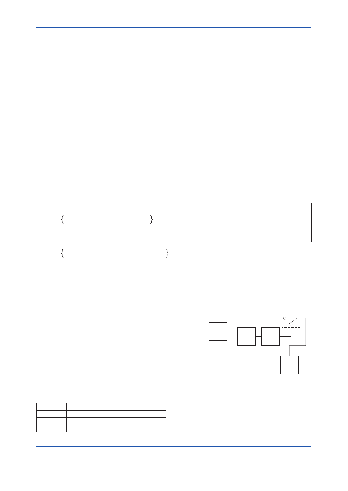
<16. PID Function Block>
16-2
16.5 PID Computation
For PID control, the PID block in a YVP110 employs
the PV-proportional and PV-derivative type PID
control algorithm (referred to as the I-PD control
algorithm) for Auto and RCas mode. This algorithm
mensures control stability against sudden changes
in the setpoint, such as when the user enters a new
setpoint value. At the same time, the I-PD algorithm
ensures excellent controllability by performing
proportional, integral, and derivative control
actions in response to changes of characteristics
in the controlled process, changes in load, and
occurrences of disturbances.
For Cas mode, PV-derivative type PID control
algorithm (referred to as the PI-D control algorithm)
is employed in order to obtain better performance
against the changes in the setpoint.
The algorithm is automatically changed by the
block according to the mode. A basic form of each
algorithm is expressed in the equation below.
In Auto / RCas mode
∆MVn=K ∆PVn+
In Cas mode
∆T
(PVn−SPn)+
Ti
Td
∆T
∆(∆PVn)
16.6 Control Output
The nal control output value, OUT, is computed
based on the change in control output ΔMVn, which
is calculated at each control period in accordance
with the aforementioned algorithm. The PID block
in a YVP110 performs the velocity type output
action for the control output. This means that the
PID block determines the value of the new control
output(OUT) by adding the change in control output
calculated in the current control period, ΔMVn, to
the current read-back value of the MV(OUT), MVRB
(BKCAL_IN). This action can be expressed as:
OUT = BKCAL_IN – ΔMVn'
ΔMVn' = ΔMVn which is scaled by PV_SCALE
and OUT_SCALE
16.7 Direction of Control Action
The direction of the control action is determined by
the Direct Acting setting in CONTROL_OPTS.
Table 16.2 Direction of Control Action
Value of
Direct Acting
True The output increases when the input
PV is greater than the setpoint SP.
False The output decreases when the input
PV is greater than the setpoint SP.
Resulting Action
∆MVn=K ∆(PVn−SPn)+
∆T
(PVn−SPn)+
Ti
Td
∆T
∆(∆PVn)
Where ;
ΔMVn = change in control output
ΔPVn = change in measured (controlled) value
= PVn – PVn–1
ΔT = control period
= period_of_execution in block header
K = proportional gain
= GAIN (= 100/proportional band)
TI = integral time = RESET
TD = derivative time = RATE
The subscripts, n and n–1, represent the sampling
time and thus PVn and PVn–1 denote the PV value
sampled most recently and the PV value sampled
at the preceding control period respectively.
The table below shows the PID control parameters.
Table 16.1 PID Control Parameters
Parameter Description Valid Range
GAIN Proportional gain 0.05 to 20
RESET Integral time 0.1 to 10,000 (seconds)
RATE Derivative time 0 to innity
16.8 Control Action Bypass
The PID control computation can be bypassed so
as to set the SP value in the control output OUT as
shown below. Setting BYPASS to on bypasses the
PID control computation.
BYPASS
CAS_IN
RCAS_IN
Figure 16.3 Control Action Bypass
Setpoint
SP
Filter
IN PV
Control
Feed
Forward
Output
OUT
F1603.ai
IM 21B04C01-01E
Page 84

<16. PID Function Block>
16-3
16.9 Feed-forward
Feed-forward is an action to add a compensation
input signal FF_VAL to the output of the PID control
computation and is typically used for feed-forward
control. In practice, the value of the change in FF_
VAL is scaled to the range of the OUT, multiplied by
the value of FF_GAIN, and then added to the PID
control computation result, as illustrated by Figure
16.4.
When the status of FF_VAL is Bad, the value of
LUV(Lust usable value) is used instead of FF_VAL.
If LUV contains no value, the feed-forward action is
not carried out.
FF_VAL
Value in engineering unit
FF_SCALE
OUT_SCALE
0-100%
X
PID computation result
Figure 16.4 Feed-forward
FF_GAIN
OUT
F1604.ai
16.10 External-output Tracking (LO)
External-output tracking is an action of outputting
the value of the remote output TRK_VAL set from
outside the PID block, as illustrated in the gure
below. External tracking is performed when the
block mode is LO.
TRK_VAL
Scaling
(based on TRK_SCALE
and OUT_SCALE)
TRK_IN_D
PID control
computation result
LO mode
Figure 16.5 External-value Tracking
To change the block mode to LO:
(1) Set Track Enable in CONTROL_OPTS (see
Section 16.12) to true.
(2) Set TRK_IN_D to true.
However, to change the block mode from Man to
LO, Track in Manual must also be set as true in
CONTROL_OPTS.
OUT
F1605.ai
16.11 Measured-value Tracking
Measured-value tracking, also referred to as SP-PV
tracking, is the action of equalizing the setpoint SP
to the measured value PV when the block mode
(MODE_BLK.actual) is Man in order to prevent a
sudden change in control output from being caused
by a mode change to Auto.
While a cascade primary control block is performing
automatic control in Auto or Cas mode, when the
mode of its secondary control block is changed from
Cas to Auto, the cascade connection is opened and
the control action of the primary block stops. The
SP of the primary controller can also be equalized
to its cascade input signal CAS_IN in this case.
The settings for measured-value tracking are made
in the parameter CONTROL_OPTS, as shown in
Table 16.3.
16.12 CONTROL_OPTS
CONTROL_OPTS is a parameter that stipulates
control options as shown below.
Table 16.3 CONTROL_OPTS of PID Block
Options in
Bit
CONTROL_
OPTS
0 Bypass
Enable
1 SP-PV Track
in Man
2 SP-PV Track
in Rout
3 SP-PV Track
in LO or IMan
4 SP Track
retained
Target
5 Direct Acting Set the PID block to be a direct
7 Track Enable While this option is set, if the value
8 Track in
Manual
9 Use PV for
BKCAL_OUT
12 Obey SP limits
if Cas or RCas
13 No OUT limits
in Manual
Switch for activating the control
action bypass
Equalizes SP to PV when MODE_
BLK.target is set to Man.
Equalizes SP to PV when MODE_
BLK.target is set to ROut.
Equalizes SP to PV when MODE_
BLK.actual is set to LO or IMan.
Equalizes SP to RCAS_IN or
CAS_IN when MODE_BLK.target
is either in IMan, LO, Man or ROut
and MODE_BLK.actual is set to
RCas or Cas.
acting controller.
of TRK_IN_D becomes '1', the
mode transfers to LO.
Set this option when the mode
should be transfered to LO even
when MODE_BLK.target is set to
Man. This option is invalid when
Track Enable option is not set.
Sets the value of PV in BKCAL_
OUT and RCAS_OUT, instead of
the value of SP.
Puts the setpoint high/low limits in
force in the Cas or RCas mode.
Disables the high/low limits for
OUT in the Man mode.
Description
IM 21B04C01-01E
Page 85

<16. PID Function Block>
16-4
16.13 Initialization and Manual Fallback (IMan)
Initialization and manual fallback denotes a set of
abnormality handling actions in which a PID block
changes mode to IMan (initialization manual) and
suspends the control action. Initialization and
manual fallback takes place only when the following
condition is met:
• The quality component of BKCAL_IN.status
(data status of BKCAL_IN) is Bad.
- OR -
• The quality component of BKCAL_IN.status is
Good (c)
- AND -
The sub-status component of BKCAL_IN.status
is FSA, LO, NI, or IR.
16.14 Manual Fallback
Manual fallback denotes an abnormality handling
action in which a PID block changes mode to Man
(manual) and suspends the control action.
The manual fallback action is enabled to take place
if the Target to Manual if BAD IN option in STATUS_
OPTS is set as true, and it takes place when the
following condition is met:
• IN.status (data status of IN) is Bad except when
the control action bypass is on.
16.14.1 STATUS_OPTS
16.15 Auto Fallback
Auto fallback denotes an action in which a PID
block changes mode from Cas to Auto and
continues automatic PID control with the user-set
setpoint. To enable the auto fallback action to take
place:
• The Target to next permitted mode if BAD CAS
IN option must be preset to true in STATUS_
OPTS.
- AND -
• Auto must be preset in MODE_BLK.permitted.
If the above settings are made, auto fallback
takes place automatically when the following
condition is met:
• CAS_IN.status (data status of cascade
setpoint) is Bad except when the control action
bypass is on.
16.16 Mode Shedding upon Computer Failure
When (1) the data status of RCAS_IN, which is the
setting received from a computer as the setpoint
SP, falls to Bad while the PID block is running in the
RCas (remote cascade) mode, or when (2) the data
status of ROUT_IN, which is the setting received
from a computer as the remote output signal, falls
to Bad while the PID block is running in the ROut
(remote output) mode; mode shedding occurs in
accordance with the SHED_OPT setting.
The table below shows the options in STATUS_
OPTS.
Table 16.4 STATUS_OPTS of PID Block
Options in
Bit
STATUS_
OPTS
0 IFS if BAD IN Sets the sub-status component
1 IFS if BAD
CAS IN
2 Use Uncertain
as Good
5 Target to
Manual if BAD
IN
9 Target to next
permitted
mode if BAD
CAS IN
of OUT.status to IFS if IN.status
is Bad except when PID control
bypass is on.
Sets the sub-status component of
OUT.status to IFS if CAS_IN.status
is Bad.
Does not regard IN as being in Bad
status when IN.status is Uncertain
(to prevent mode transitions
from being affected when it is
Uncertain).
Automatically changes the value of
MODE_BLK.target to Man when IN
falls to Bad status.
Automatically changes the value
of MODE_BLK.target to Auto (or to
Man if Auto is not set in Permitted)
when CAS_IN falls to Bad status.
Description
IM 21B04C01-01E
Page 86

<16. PID Function Block>
16-5
Table 16.5 SHED_OPT of PID Block
Available
Setting for
Actions upon Computer Failure
SHED_OPT
Normal shed,
normal return
Sets MODE_BLK.actual to Cas*
and leaves MODE_BLK.target
1
,
unchanged.
Normal shed, no
return
Shed to Auto,
normal return
Sets both MODE_BLK.actual and
MODE_BLK.target to Cas*
1
.
Sets MODE_BLK.actual to Auto*
and leaves MODE_BLK.target
2
,
unchanged.
Shed to Auto, no
return
Shed to Manual,
normal return
Sets both MODE_BLK.actual and
MODE_BLK.target to Auto*
2
.
Sets MODE_BLK.actual to Man,
and leaves MODE_BLK.target
unchanged.
Shed to Manual,
no return
Shed to retained
target, normal
return
Sets both MODE_BLK.actual and
MODE_BLK.target to Man.
If Cas is set in MODE_BLK.target,
- sets MODE_BLK.actual to Cas*
and
1
- leaves MODE_BLK.target
unchanged.
If Cas is not set in MODE_BLK.
target,
- sets MODE_BLK.actual to Auto*
2
and
- leaves MODE_BLK.target
unchanged.
Shed to retained
target, no return
If Cas is set in MODE_BLK.target,
sets:
- MODE_BLK.actual to Cas, and
- MODE_BLK.target to Cas*
1
, too.
If Cas is not set in MODE_BLK.
target, sets:
- MODE_BLK.actual to Auto*
2
, and
- MODE_BLK.target to Cas.
*1: The modes to which the PID block can transfer are limited
to those set in MODE_BLK.permitted, and the priority
levels of modes are as shown below. In fact, if Normal
shed, normal return is set for SHED_OPT, detection of a
computer failure causes MODE_BLK.actual to change
to Cas, Auto, or Man, whichever is set in MODE_BLK.
permitted and has the lowest priority level.
Higher priority level
Man
Auto
Cas
RCas
ROut
*2: Only when Auto is set as permitted mode.
NOTE: If a control block is connected as a cascade
primary block of the PID block in question, a mode
transition of the PID block to Cas occurs in the following
sequence due to initialization of the cascade connection:
RCas or ROut → Auto → Cas.
Lower priority level
16.17 Alarms
There are two kinds of alarms generated by a PID
block: block and process alarms.
16.17.1 Block Alarm (BLOCK_ALM)
The block alarm BLOCK_ALM is generated upon
occurrence of either of the following errors (values
set in BLOCK_ERR) and noties the content of
BLOCK_ERR.
Bit
Value of
BLOCK_ERR
4 Local Override MODE_BLK.actual of the PID
block is LO.
7 Input Failure The status of PV is Bad.
(The status of IN is Bad, or the
status of IN is Uncertain and
“Use Uncertain as Good” is false
in STATUS_OPTS).
15 Out of Service MODE_BLK.target of the PID
block is O/S.
16.17.2 Process Alarms
There are six types of process alarms. Only one
process alarm can be generated at a time, and
the process alarm having the highest priority level
from among those occurring at the same time is
generated. The priority level is set for each process
alarm type.
Process
Alarm
HI_HI_ALM Occurs when the PV
HI_ALM Occurs when the PV
LO_ALM Occurs when the PV
LO_LO_ALM Occurs when the PV
DV_HI_ALM Occurs when the value
DV_LO_ALM Occurs when the value
Cause of Occurrence
increases above the
HI_HI_LIM value.
increases above HI_LIM
value.
decreases below the
LO_LIM value.
decreases below the
LO_LO_LIM value.
of [PV -SP] increases
above the DV_HI_LIM
value.
of [PV -SP] decreases
below the DV_LO_LIM
value.
Condition
Parameter
Containing
Priority
Level
Setting
HI_HI_PRI
HI_PRI
LO_PRI
LO_LO_LIM
DV_HI_PRI
DV_LO_PRI
IM 21B04C01-01E
Page 87

<17. IS Function Block>
SELECTED
17-1
17. IS Function Block
The function of the Input Selector (IS) block is to automatically select one signal from multiple input signals
using a specied selection method.
The IS block is used for selective control in which one measured quantity is selected from multiple measured
quantities to be transmitted to the controller as a controlled variable. This feature is primarily used for
temperature control systems.
17.1 IS Function Block Schematic
The following shows the Input Selector function block schematic.
IN_1
IN_2
IN_3
IN_4
IN_5
IN_6
IN_7
IN_8
DISABLE_1
DISABLE_2
DISABLE_3
DISABLE_4
DISABLE_5
DISABLE_6
DISABLE_7
DISABLE_8
OP_SELECT
SELECTION
First Good
MINIMUM
MAXIMUM
MIDDLE
AVERAGE
Latched Good
Man
MODE
OUT
Auto
Configuration
STATUS_OPTS
SELECT_TYPE
MIN_Good
Figure 17.1 IS Block
Input Parameters (Input Terms)
IN_1 : Block input 1
IN_2 : Block input 2
IN_3 : Block input 3
IN_4 : Block input 4
IN_5 : Block input 5
IN_6 : Block input 6
IN_7 : Block input 7
IN_8 : Block input 8
DISABLE_1 : Selector switch 1 to disable input 1 from being selected
DISABLE_2 : Selector switch 2 to disable input 2 from being selected
DISABLE_3 : Selector switch 3 to disable input 3 from being selected
DISABLE_4 : Selector switch 4 to disable input 4 from being selected
DISABLE_5 : Selector switch 5 to disable input 5 from being selected
DISABLE_6 : Selector switch 6 to disable input 6 from being selected
DISABLE_7 : Selector switch 7 to disable input 7 from being selected
DISABLE_8 : Selector switch 8 to disable input 8 from being selected
OP_SELECT : A parameter which can be set by an operator to forcibly employ the input of the selected
number
IM 21B04C01-01E
Page 88

<17. IS Function Block>
17-2
Output Parameters (Computation or Selection Results)
OUT: Block output
SELECTED: Indicates the input number selected using the alternatives.
Other Parameters
OUT_RANGE : Sets the OUT range. This setting does not affect instrument action.
STATUS_OPTS : Option used to specify the handling of various statuses.
SELECT_TYPE : Determines the input selection algorithm.
MIN_GOOD : Parameter specifying the minimum required number of inputs with “good” status. If the
number of inputs that are “good” is less than the value of MIN_GOOD, input selection is
canceled.
Mode
O/S : Allows conguration change, but disables input value output.
Man : Allows internal processing, but the output value may vary depending on the denition of usage
conditions.
Auto : Outputs the input value.
The Input Selector (IS) block offers a maximum of eight input alternatives and generates the output according
to the congured action. This block generally receives inputs from the Analog Input (AI) function block. The
function of the IS block is to select a maximum, minimum, middle, average, “rst good,” or “latched good”
signal. The block combines parameter conguration (DISABLE_n) and option (“rst good”) to give priority to
alternative(s) or to function as a rotary position switch. When used as a rotary position switch, the block can
receive operator inputs or switch information from connected inputs.
The IS block supports the concept of middle selection. This function outputs the average of two middle signals
if even multiple valid signals are congured or a middle signal if odd multiple valid signals are congured.
Application of the block is to supply a selected control signal in the forward path.
The SELECTED parameter is the 2nd output indicating which input has been selected using the algorithm.
IM 21B04C01-01E
Page 89

<17. IS Function Block>
F1702.ai
OUT = certain retained
17.2 Input Section
17.2.1 Mode Handling
The Input Selector block’s operations are determined by the mode (parameter name: MODE_BLK). The
following describes operations in each mode.
17-3
Supported
Role
Mode
O/S
(Out of Service)
• System-stopped status
• Allows you to make changes to
conguration.
Man
• If you do not want to output the
value and status from IN or if the
value or status thus output is not
preferable, you can manually
transmit the value to OUT.
Auto
• Automatic system operation status
17.2.2 MIN_GOOD Handling
If there is no selectable input or if the number of selectable inputs is less than the value of MIN_GOOD,
SELECTED becomes “0.”
A case where the number of valid INs is less than the value of MIN_GOOD:
SELECTION
IN_1 = 23
IN_2 = 34.5
IN_3 = 45
IN_4 = 2.34
IN_5 = 23.6
IN_6 = 15.5
IN_7 = 32.5
IN_8 = 27.4
DISABLE_1 = ON
DISABLE_2 = ON
DISABLE_3 = OFF
DISABLE_4 = ON
DISABLE_5 = OFF
DISABLE_6 = ON
DISABLE_7 = ON
DISABLE_8 = ON
SELECT_TYPE = Middle
STATUS_OPTS
MIN_GOOD = 3
value that was
output previously
SELECTED = 0
OP_SELECT = 1
Figure 17.2 Example (1)
This example restricts the valid inputs using DISABLE_n, and the inputs are enabled only at DISABLE_3 and
DISABLE_5. Because the effective number of MIN_Good is 3, the input specied by OP_SELECT will not be
output.
IM 21B04C01-01E
Page 90

<17. IS Function Block>
17-4
17.3 Selection
The following processing is performed after completing input processing. If the number of valid inputs is less
than the value of MIN_Good, no input selection is made.
17.3.1 OP_SELECT Handling
When a value other than “0” (that is, 1 to 8) is selected for OP_SELECT:
The IS block selects the input of the number specied by OP_SELECT regardless of the setting of SELECT_
TYPE, propagates the value of that input to OUT, and transmits the input number to SELECTED.
SELECTION
IN_1 = 23
IN_2 = 34.5
IN_3 = 45
IN_4 = 2.34
IN_5 = 23.6
IN_6 = 15.5
IN_7 = 32.5
IN_8 = 27.4
DISABLE_1 = OFF
DISABLE_2 = OFF
DISABLE_3 = OFF
DISABLE_4 = OFF
DISABLE_5 = OFF
DISABLE_6 = OFF
DISABLE_7 = OFF
DISABLE_8 = OFF
SELECT_TYPE = Minimum
STATUS_OPTS
MIN_GOOD = 1
OUT = 45
SELECTED = 3
OP_SELECT = 3
F1703.ai
Figure 17.3 Example (2)
In the above example, SELECT_TYPE is set to Minimum. However, because OP_SELECT species the value
and number of IN_3, the value and number of this specied IN are transmitted to OUT and SELECTED.
* Note: Even if the IN specied by OP_SELECT is an invalid input (the corresponding DISABLE parameter is ON or the IN’s status is
“bad”), the value and status of that IN are transmitted to OUT.
IM 21B04C01-01E
Page 91
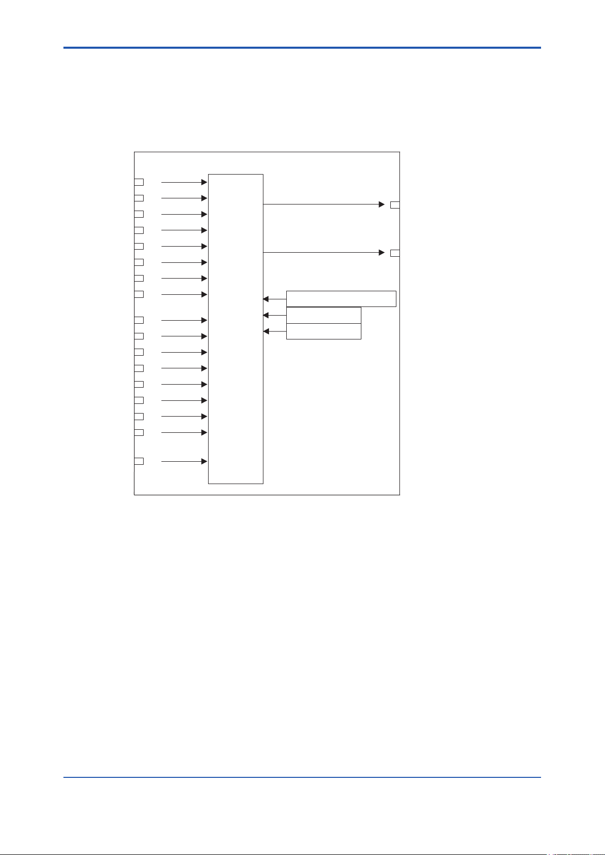
<17. IS Function Block>
17-5
17.3.2 SELECTION Handling
If the value of OP_SELECT is “0,” input selection using SELECT_TYPE is enabled.
When SELECT TYPE is “rst good”
The IS block selects the input with the smallest input number among valid inputs and transmits the value of that
input to OUT. The number of the selected input is transmitted to SELECTED.
SELECTION
IN_1 = 23
IN_2 = 34.5
IN_3 = 45
IN_4 = 2.34
IN_5 = 23.6
IN_6 = 15.5
IN_7 = 32.5
IN_8 = 27.4
DISABLE_1 = ON
DISABLE_2 = OFF
DISABLE_3 = OFF
DISABLE_4 = OFF
DISABLE_5 = OFF
DISABLE_6 = OFF
DISABLE_7 = OFF
DISABLE_8 = OFF
SELECT_TYPE = First Good
STATUS_OPTS
MIN_GOOD = 1
OUT = 34.5
SELECTED = 2
OP_SELECT = 0
F1704.ai
Figure 17.4 Example (3)
Because DISABLE_1 is ON, IN_1 is disabled, and IN_2 is selected for output. If DISABLE_1 is turned OFF,
the output changes from IN_2 to IN_1. That is, the valid IN with the smaller input number is always selected for
output.
IM 21B04C01-01E
Page 92
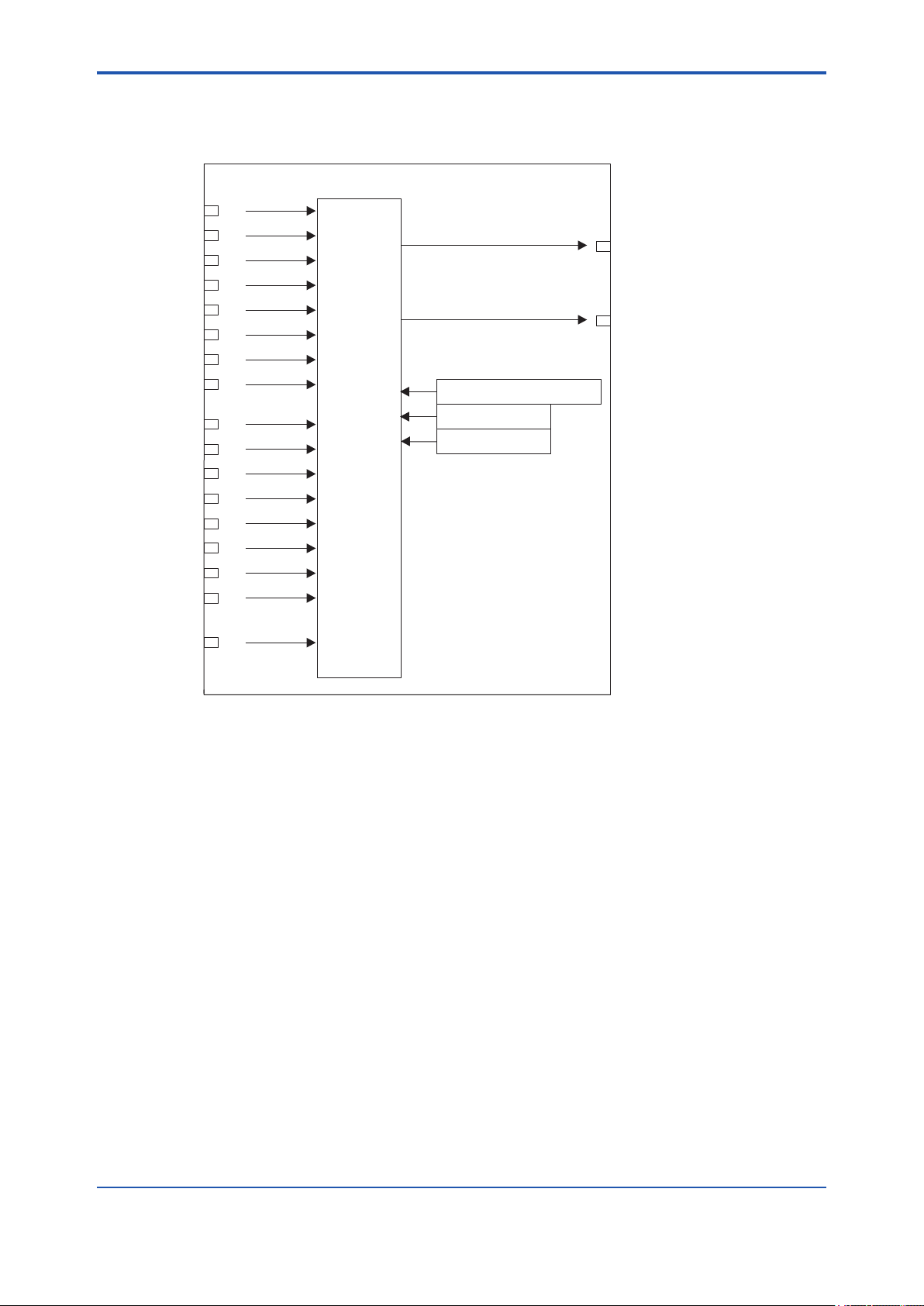
<17. IS Function Block>
17-6
When SELECT TYPE is “Minimum”
The IS block selects the input with the minimum value among valid inputs and transmits the value of that input
to OUT. The number of the selected input is transmitted to SELECTED.
SELECTION
IN_1 = 23
IN_2 = 34.5
IN_3 = 45
IN_4 = 2.34
IN_5 = 23.6
IN_6 = 15.5
IN_7 = 32.5
IN_8 = 27.4
DISABLE_1 = OFF
DISABLE_2 = OFF
DISABLE_3 = OFF
DISABLE_4 = OFF
DISABLE_5 = OFF
DISABLE_6 = OFF
DISABLE_7 = OFF
DISABLE_8 = OFF
SELECT_TYPE = Minimum
STATUS_OPTS
MIN_GOOD = 1
OUT = 2.34
SELECTED = 4
OP_SELECT = 0
Figure 17.5 Example (4)
F1705.ai
IM 21B04C01-01E
Page 93

<17. IS Function Block>
17-7
When SELECT TYPE is “Maximum”
The IS block selects the input with the maximum value among valid inputs and transmits the value of that input
to OUT. The number of the selected input is transmitted to SELECTED.
SELECTION
IN_1 = 23
IN_2 = 34.5
IN_3 = 45
IN_4 = 2.34
IN_5 = 23.6
IN_6 = 15.5
IN_7 = 32.5
IN_8 = 27.4
DISABLE_1 = OFF
DISABLE_2 = ON
DISABLE_3 = ON
DISABLE_4 = OFF
DISABLE_5 = OFF
DISABLE_6 = OFF
DISABLE_7 = OFF
DISABLE_8 = OFF
SELECT_TYPE = Maximum
STATUS_OPTS
MIN_GOOD = 1
OUT = 32.5
SELECTED = 7
OP_SELECT = 0
F1706.ai
Figure 17.6 Example (5)
Because DISABLE_2 and DISABLE_3 are ON, IN_2 and IN_3 are disabled, and the IN with the maximum
value among the remaining IN_n is selected for output. In the above example, since IN_7 has the maximum
value among the remaining valid INs, it is output.
IM 21B04C01-01E
Page 94
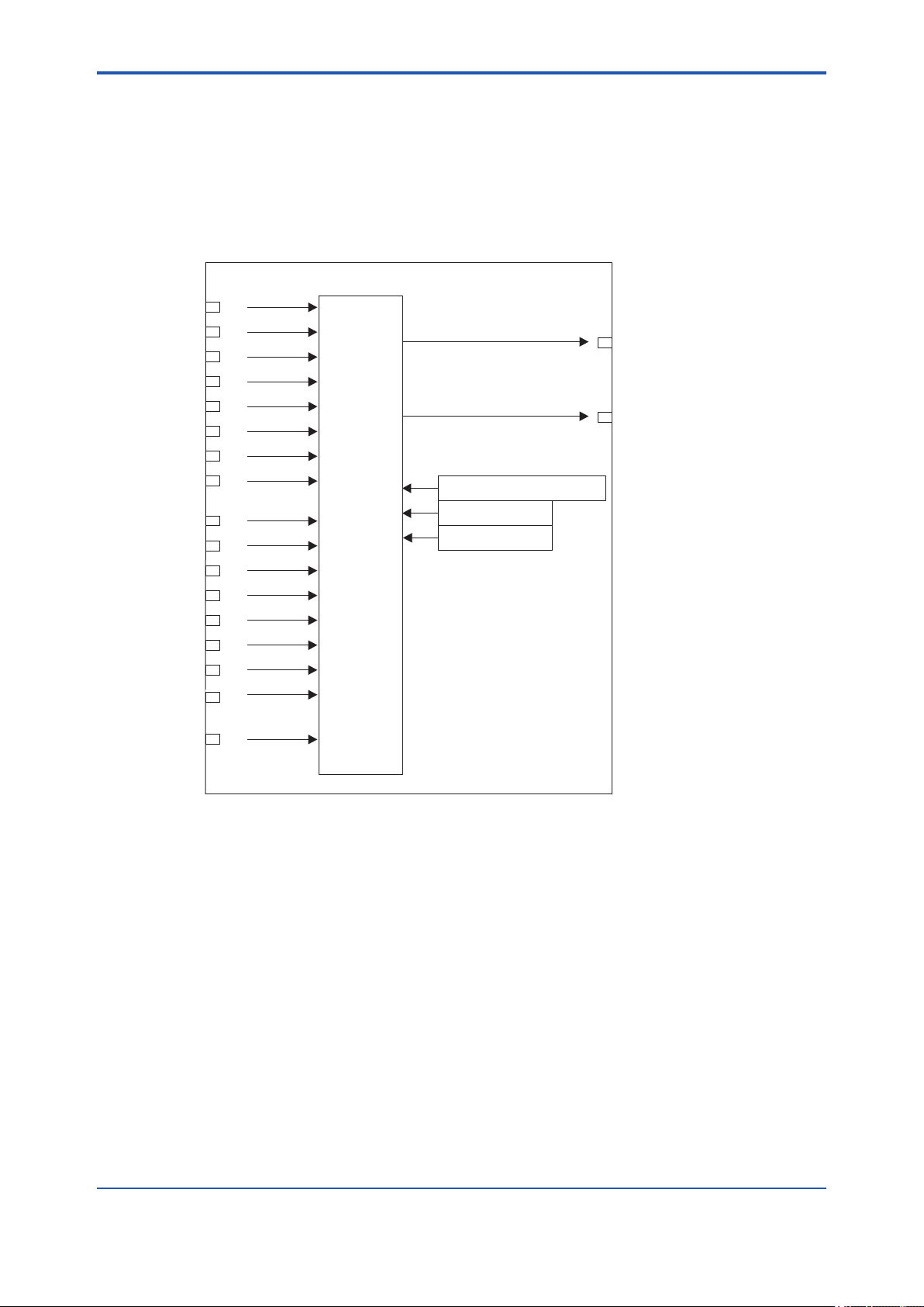
<17. IS Function Block>
IN_1 = 23
SELECT_TYPE = Middle
STATUS_OPTS
MIN_GOOD = 1
SELECTION
SELECTED = 7
OUT = 19.55
(IN_5+IN_6)/2 = 19.55
IN_2 = 34.5
IN_3 = 45
IN_4 = 2.34
IN_5 = 23.6
IN_6 = 15.5
IN_7 = 32.5
IN_8 = 27.4
DISABLE_1 = ON
DISABLE_2 = ON
DISABLE_3 = OFF
DISABLE_4 = OFF
DISABLE_5 = OFF
DISABLE_6 = OFF
DISABLE_7 = ON
DISABLE_8 = ON
OP_SELECT = 0
F1707.ai
17-8
When SELECT TYPE is “Middle”
If there is more than one valid input and the number of such input is an odd number, the value of the middle
input will be transmitted to OUT. If there is an even number of valid inputs, the average of the middle two inputs
is transmitted to OUT. If the average is used for OUT, the block transmits “0” to SELECTED, while it transmits
the number of the input used for the middle for other cases. If the number of valid inputs is 1, it is irrelevant to
selection by “Middle” selector action. The following shows an example of selection by “Middle” selector action.
If there is an even number of valid inputs:
Figure 17.7 Example (6)
Because DISABLE_1, DISABLE_2, DISABLE_7, and DISABLE_8 are ON, the corresponding IN_1, IN_2,
IN_7, and IN_8 are disabled and the remaining four INs are enabled. Furthermore, because IN_3 has the
maximum value and IN_4 has the minimum value among the valid INs, they are not selected and the average
of IN_5 and IN_6 inputs is output. When the average is selected for OUT, SELECTED is set to “0.”
IM 21B04C01-01E
Page 95

<17. IS Function Block>
If there is an odd number of valid inputs:
SELECTION
IN_1 = 23
IN_2 = 34.5
IN_3 = 45
IN_4 = 2.34
IN_5 = 23.6
IN_6 = 15.5
IN_7 = 32.5
IN_8 = 27.4
DISABLE_1 = OFF
DISABLE_2 = OFF
DISABLE_3 = OFF
DISABLE_4 = OFF
DISABLE_5 = OFF
DISABLE_6 = OFF
DISABLE_7 = OFF
DISABLE_8 = ON
SELECT_TYPE = Middle
STATUS_OPTS
MIN_GOOD = 1
OUT = 23.6
SELECTED = 5
17-9
OP_SELECT = 0
F1708.ai
Figure 17.8 Example (7)
If the number of valid INs is an odd multiple, the IN with the middle value will be output. In the above example,
the IN_5 input having the middle value is output.
IM 21B04C01-01E
Page 96

<17. IS Function Block>
17-10
When SELECT TYPE is “Average”
The block calculates the average of the valid inputs and transmits it to OUT. The number of inputs used to
calculate its value is indicated in SELECTED.
SELECTION
IN_1 = 23
IN_2 = 34.5
IN_3 = 45
IN_4 = 2.34
IN_5 = 23.6
IN_6 = 15.5
IN_7 = 32.5
IN_8 = 27.4
DISABLE_1 = OFF
DISABLE_2 = OFF
DISABLE_3 = OFF
DISABLE_4 = OFF
DISABLE_5 = OFF
DISABLE_6 = OFF
DISABLE_7 = OFF
DISABLE_8 = OFF
SELECT_TYPE = Average
STATUS_OPTS
MIN_GOOD = 1
OUT = 25.48
(IN_1+···+IN_8)/8 = 25.48
SELECTED = 8
OP_SELECT = 0
F1709.ai
Figure17.9 Example (8)
When SELECT TYPE is “Latched Good”
The valid input with the smaller input number is selected as an output and is held until it becomes invalid.
When it becomes invalid, the next valid input will be selected as an output regardless of the magnitude of the
value. Even if an input with the input number smaller than that of the currently selected input recovers, the
current selection is held.
Assuming that IN_2 is the valid input with the smallest input number, the order of input selection is IN_2 →
IN_3 → ...→ IN_8 → IN_1 → ....
If the power is turned OFF and then ON with SELECT TYPE set to “Latched Good,” input selection starts with
the IN that was selected before the power was turned OFF.
IM 21B04C01-01E
Page 97

<17. IS Function Block>
17-11
17.4 Output Processing
17.4.1 Handling of SELECTED
For the value output to SELECTED when OP_SELECT has been selected (that is, not “0”), the number
specied by OP_SELECT will be stored as is.
However, “0” is stored in the SELECTED in the following cases:
1. If there is no valid input;
2. If the value of MIN_GOOD is greater than the number of valid inputs;
3. If the input status is “bad” or “uncertain” when the value of OP_SELECT is anything other than “0”
(with the exception of the case where the “Uncertain as good” bit in STATUS_OPTS is set.);
4. If the value of OP_SELECT is greater than 8, which is the maximum number of inputs;
5. If the value is out of the SELECT_TYPE setting range when the value of OP_SELECT is zero.
As long as there is one valid input, even an invalid input can be selected for OP_SELECT.
If the number of valid inputs is greater than the value of MIN_GOOD, the number of the input (including an
invalid input) specied by OP_SELECT will be stored in SELECTED. Therefore, even if an invalid input is
selected, SELECTED does not become zero.
If no input is selected for OP_SELECT, the output of SELECTED will depend on SELECT_TYPE.
The Table 17.1 shows the value of SELECTED according to the number of valid inputs and SELECT_TYPE.
Table17.1 Value of SELECTED According to Inputs
Valid
Inputs
None 0 (zero) 0 (zero) 0 (zero) 0 (zero)
1 # of IN with a
Multiple INs
(Even # of INs)
Multiple INs
(Odd # of INs)
Table 17.2 Value of SELECTED According to the Mode
O/S MAN AUTO
0 0 0 to 8
SELECT_TYPE =
First Good
smaller value
MINIMUM, MAXIMUM, or Latched Good
SELECT_TYPE =
# of selected IN # of selected IN 1
Value of SELECTED
SELECT_TYPE =
MIDDLE
0 (the average is
taken)
# of IN with the
middle value
SELECT_TYPE =
AVERAGE
# of valid INs (the
average is taken)
IM 21B04C01-01E
Page 98

<17. IS Function Block>
17.4.2 OUT Processing
OUT is an output parameter used to send the value selected in the IS block to another function block.
The following describes OUT processing.
Table 17.3 Block Mode and Value
Mode Value
O/S
Man
Value specied by MIN_Good > the number of
valid inputs
If there is no valid input
If the input status is “bad” or “uncertain” when
the value of OP_SELECT is anything other than
“0” (with the exception of the case where the
“Uncertain as good” bit in STATUS_OPTS is set)
If the value of OP_SELECT is greater than 8,
which is the maximum number of inputs
If OP_SELECT is enabled
If the value is out of the SELECT_TYPE setting
range when the value of OP_SELECT is “0”
If SELECT_TYPE is “First Good”
A
u
If SELECT_TYPE is “MINIMUM”
t
o
If SELECT_TYPE is “MAXIMUM”
If SELECT_TYPE is “MIDDLE”
(There is an even multiple number of valid inputs.)
If SELECT_TYPE is “MIDDLE”
(There is an odd multiple number of valid inputs.)
If SELECT_TYPE is “AVERAGE”
If SELECT_TYPE is “Latched Good”
• The previous value is output. (At startup, the initial value is
used).
• Writable (the operator may change the value.)
• The previous value is output.
• Not writable
• Zero
• Not writable
• The value of the selected input is output.
• Not writable
• The previous value is output.
• Not writable
• The value of a valid input with the smallest input number is
output.
• Not writable
• The minimum value among the values of the valid inputs is
output.
• Not writable
• The maximum value among the values of the valid inputs is
output.
• Not writable
• Because two inputs are positioned in the middle of the values
of even multiple valid inputs, the average of the values of these
two inputs is output.
• Not writable
• The value of the input positioned in the middle of the values of
odd multiple valid inputs is output.
• Not writable
• The value obtained by dividing the added value of the values of
valid inputs by the number of these inputs is output.
• Not writable
• The value of a valid input with the smallest input number is
output.
• Not writable
17-12
Table 17.4 Condition and Mode
Condition (Listed in priority sequence) Mode
If the Actual is in O/S O/S
If the “Uncertain if Man mode” bit in STATUS_OPTS is set and the Actual is in Man Man
If the “Uncertain if Man mode” bit in STATUS_OPTS is not set and the Actual is in Man Man
Values specied by MIN_Good > the number of valid inputs Auto
If there is no valid input Auto
If the input status is “bad” or “uncertain” when the value of OP_SELECT is anything other than “0”
(with the exception of the case where the “Uncertain as good” bit in STATUS_OPTS is set)
If the value of OP_SELECT is greater than 8, which is the maximum number of inputs Auto
If OP_SELECT has selected IN whose status is “bad” or “uncertain”
(See the item “Transition of Sub-status in the Case Where OP_SELECT is Selected.”)
If the value is out of the SELECT_TYPE setting range when the value of OP_SELECT is “0” Auto
Auto
Auto
IM 21B04C01-01E
Page 99

<17. IS Function Block>
17-13
17.4.3 STATUS_OPTS
Bit Description
Use Uncertain as
Good
Causes all inputs (OP_SELECT,
IN_n, and DISABLE_n) the
status of which is “uncertain,”
to be handled as “good” (NC)
status inputs and the others to be
handled as ”bad” status inputs.
Uncertain if Man
mode
When the mode is Man, the
status of OUT is interpreted as
“uncertain.” (This does not apply to
SELECTED.)
17.5 Application Example
The following describes the temperature control
system of a xed bed-type reactor. In this case,
there are instances where the point showing the
maximum temperature changes due to catalytic
deterioration, raw material ow, etc. Therefore, a
large number of measurement points are provided,
and the maximum value obtained among these
measurement points is input to the controller to
control reactor temperature.
Basic operations and work sequence:
1. The IS block obtains values and status
information from AI.
2. The block selects the AI information using the
alternatives.
3. The block displays and outputs the information
selected by SELECTED.
Raw material
AI1
Catalytic reactor
AI2
IS
PID
AO
Refrigerant
AI3
AI4
Product
F1710.ai
Figure 17.10 Temperature Control System of a Fixed
Bed-type Reactor
AI1
AI
AI1
AI1
AI1 AI4
OUT
OUT
OUT
OUT
IS
IN_1 4 OUT
PID
OUTIN
BKCAL_I N
AO
CAS_IN
BKCAL_O UT
F1711.ai
Figure 17.11 Example of Scheduling
AI1: Temperature 1, AI2: Temperature 2,
AI3: Temperature 3, AI4: Temperature 4
IS: SELECT_TYPE = MAX
IM 21B04C01-01E
Page 100
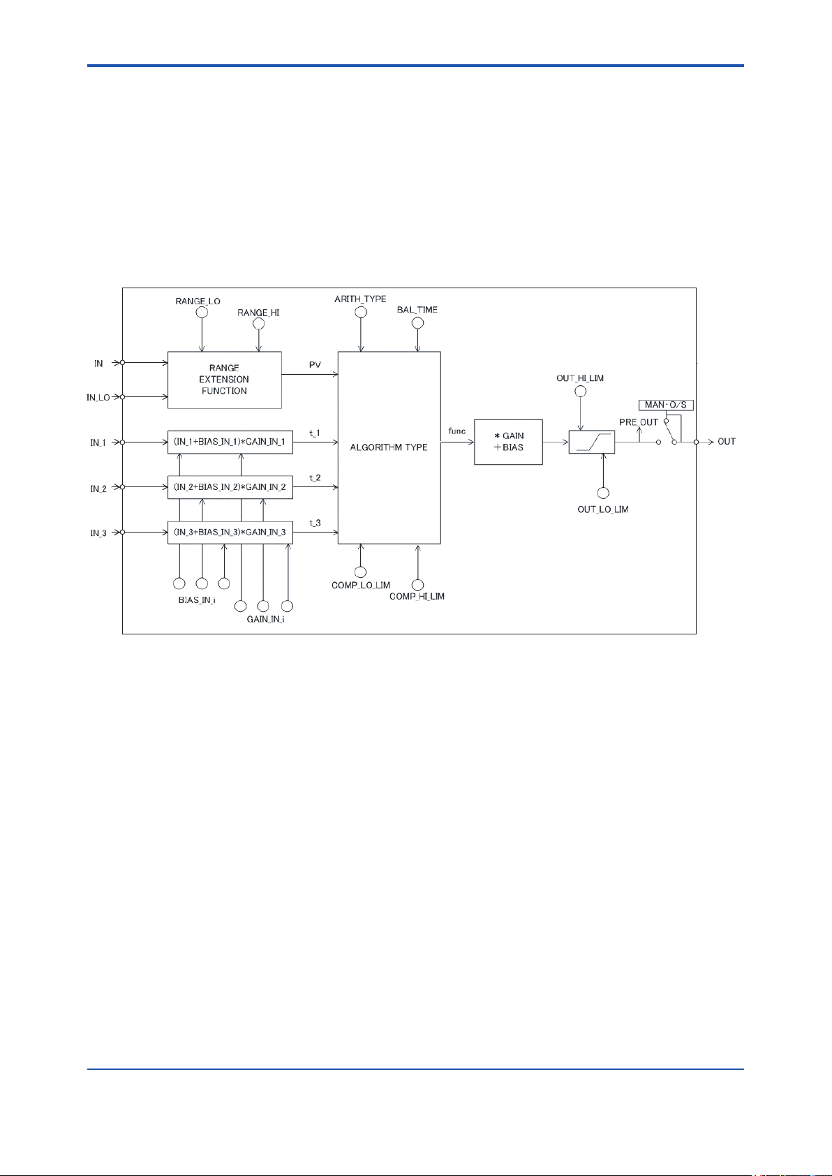
<18. AR Function Block>
18. AR Function Block
The Arithmetic (AR) block switches two main inputs of different measurement ranges seamlessly and
combines the result with three auxiliary inputs through the selected compensation function (10 types) to
calculate the output.
18.1 AR Function Block Schematic
The diagram below shows the Arithmetic block schematic.
18-1
F1801.ai
Figure 18.1 AR Block
The Arithmetic block is divided into three sections:
• Input section: Makes a go/no-go decision on the use of an input value, switches the range, and determines
the PV status.
• Computation section: Makes calculations through ARITH_TYPE.
• Output section: Applies gain multiplication and bias addition to the calculated result to perform limitation
processing for output.
* The range extension function compensates the IN and IN_LO input values when two devices with different ranges are connected, to
make smooth input switching.
IM 21B04C01-01E
 Loading...