

Page 1

Y
User’s
YTA Series
Manual
Temperature Transmitter
(BRAIN Protocol)
IM 01C50T03-01E
IM 01C50T03-01E
okogawa Electric Corporation
5th Edition
Page 2

CONTENTS
CONTENTS
1. INTRODUCTION..........................................................................................1-1
■ Regarding This Manual ............................................................................. 1-1
■ For Safe Use of Product ........................................................................... 1-2
■ Warranty .................................................................................................... 1-2
■ ATEX Documentation................................................................................ 1-3
2. CONDITIONS OF COMMUNICATION LINE............................................... 2-1
2.1 Interconnection Between YTA and BT200 ......................................... 2-1
2.2 Communication Line Requirements.................................................... 2-1
3. OPERATION ................................................................................................ 3-1
3.1 Parameters Description....................................................................... 3-1
3.2 Setting Parameters ............................................................................. 3-4
3.2.1 Sensor Configuration .................................................................... 3-4
3.2.2 Process Variables Mapping ......................................................... 3-5
3.2.3 Unit Setting................................................................................... 3-6
3.2.4 Range Setting............................................................................... 3-6
3.2.5 Setting Damping Time Constant .................................................. 3-6
3.2.6 Tag Number and Memo Writing ................................................... 3-6
3.2.7 Forced Output Function ............................................................... 3-7
3.2.8 Integral Indicator Display Function ............................................... 3-7
3.2.9 Burn Out Function ...................................................................... 3-10
3.2.10 Reverse Output Function ........................................................... 3-10
3.2.11 Sensor Backup Function (For Model YTA320).......................... 3-10
3.2.12 Copy the Setting Data................................................................ 3-11
3.2.13 Write Protect Function ................................................................ 3-11
3.2.14 Sensor Trim................................................................................ 3-12
3.2.15 Output Trim ................................................................................ 3-13
3.2.16 CJC Selection............................................................................. 3-14
4. SELF-DIAGNOSTICS .................................................................................. 4-1
4.1 Error Message..................................................................................... 4-1
4.2 Warning ............................................................................................... 4-3
4.3 Logging Function................................................................................. 4-5
4.3.1 Error Log ...................................................................................... 4-5
4.3.2 Min/Max Log................................................................................. 4-5
4.3.3 Operation Time ............................................................................. 4-5
4.3.4 Power Check ................................................................................ 4-5
4.3.5 BRAIN communication BCC error occurrence rate ..................... 4-5
5. LIST OF PARAMETERS ............................................................................. 5-1
FD No. IM 01C50T03-01E
5th Edition: Sep. 2006 (KP)
All Rights Reserved, Copyright © 1998, Yokogawa Electric Corporation
i
IM 01C50T03-01E
Page 3

CONTENTS
APPENDIX A. OPERATION OF BRAIN TERMINAL BT200 ............................. A-1
A.1 Operation Key Arrangement ...............................................................A-1
A.2 Function of Operation Keys ................................................................A-2
A.2.1 Entry of Alphanumeric Characters ...............................................A-2
A.2.2 Function Keys...............................................................................A-3
A.3 Calling of Menu Address..................................................................... A-4
A.3.1 Data Display with BT200 .............................................................. A-5
A.3.2 Data Setting with BT200 .............................................................. A-5
APPENDIX B. THE SENSOR MATCHING FUNCTION ..................................... B-1
B.1 Specifications ......................................................................................B-1
B.2 Operations (The Sensor Matching Function)...................................... B-2
APPENDIX C. SAFETY INSTRUMENTED SYSTEMS INSTALLATION ......... C-1
C.1 Scope and Purpose ............................................................................ C-1
C.2 Using the YTA for an SIS Application ................................................C-1
C.2.1 Safety Accuracy ...........................................................................C-1
C.2.2 Diagnostic Response Time ..........................................................C-1
C.2.3 Setup ............................................................................................C-1
C.2.4 Required Parameter Settings .......................................................C-1
C.2.5 Proof Testing................................................................................ C-1
C.2.6 Repair and Replacement .............................................................C-2
C.2.7 Startup Time .................................................................................C-2
C.2.8 Firmware Update..........................................................................C-2
C.2.9 Reliability Data ............................................................................. C-3
C.2.10 Lifetime Limits ..............................................................................C-3
C.2.11 Environmental Limits ....................................................................C-3
C.2.12 Application Limits .........................................................................C-3
C.3 Terms and Definitions......................................................................... C-3
REVISION RECORD
ii
IM 01C50T03-01E
Page 4

1. INTRODUCTION
1. INTRODUCTION
Thank you for purchasing the YTA series Temperature
Transmitter.
The YTA temperature transmitter is fully factory-tested
according to the specifications indicated on your order.
This manual describes BRAIN communication functions of the model YTA110, YTA310, and YTA320
temperature transmitters and the various settings for
temperature transmitter functions that can be set via the
BT200 handheld terminal. The BT200 BRAIN terminal
is required to change the settings of internal transmitter
parameters.
In order for the YTA temperature transmitter to be
fully functional and to operate in an efficient manner,
read the instruction manual carefully to become
familiar with the functions and operation as well as
handling.
See User’s Manual IM 01C00A11-01E for details
related to using the BT200 BRAIN terminal. For
details of mounting, wiring and maintenance of this
transmitter, see the separate User’s Manual IM
01C50B01-01E.
䊏 Regarding This Manual
• The following safety symbol marks are used in this
Manual:
WARNING
Indicates a potentially hazardous situation which,
if not avoided, could result in death or serious
injury.
CAUTION
Indicates a potentially hazardous situation which,
if not avoided, may result in minor or moderate
injury. It may also be used to alert against
unsafe practices.
IMPORTANT
Indicates that operating the hardware or software
in this manner may damage it or lead to system
failure.
•This manual should be passed on to the end user.
• The contents of this manual are subject to change
without prior notice.
• All rights reserved. No part of this manual may be
reproduced in any form without Yokogawa’s written
permission.
• Yokogawa makes no warranty of any kind with
regard to this manual, including, but not limited to,
implied warranty of merchantability and fitness for a
particular purpose.
• If any question arises or errors are found, or if any
information is missing from this manual, please
inform the nearest Yokogawa sales office.
• The specifications covered by this manual are
limited to those for the standard type under the
specified model number break-down and do not
cover custom-made instrument.
• Please note that changes in the specifications,
construction, or component parts of the instrument
may not immediately be reflected in this manual at
the time of change, provided that postponement of
revisions will not cause difficulty to the user from a
functional or performance standpoint.
NOTE
Draws attention to information essential for
understanding the operation and features.
1-1
IM 01C50T03-01E
Page 5

1. INTRODUCTION
䊏 For Safe Use of Product
For the protection and safety of the operator and the
instrument or the system including the instrument,
please be sure to follow the instructions on safety
described in this manual when handling this instrument. In case the instrument is handled in contradiction
to these instructions, Yokogawa does not guarantee
safety. Please give your attention to the followings.
(a) Installation
• The instrument must be installed by an expert
engineer or a skilled personnel. The procedures
described about INSTALLATION are not permitted
for operators.
• In case of high process temperature, care should be
taken not to burn yourself because the surface of the
case reaches a high temperature.
• All installation shall comply with local installation
requirement and local electrical code.
(b) Wiring
• The instrument must be installed by an expert
engineer or a skilled personnel. The procedures
described about WIRING are not permitted for
operators.
• Please confirm that voltages between the power
supply and the instrument before connecting the
power cables and that the cables are not powered
before connecting.
(c) Maintenance
• Please do not carry out except being written to a
maintenance descriptions. When these procedures
are needed, please contact nearest YOKOGAWA
office.
•Care should be taken to prevent the build up of drift,
dust or other material on the display glass and
name plate. In case of its maintenance, soft and dry
cloth is used.
䊏 Warranty
•The warranty shall cover the period noted on the
quotation presented to the purchaser at the time of
purchase. Problems occurred during the warranty
period shall basically be repaired free of charge.
• In case of problems, the customer should contact the
Yokogawa representative from which the instrument
was purchased, or the nearest Yokogawa office.
• If a problem arises with this instrument, please
inform us of the nature of the problem and the
circumstances under which it developed, including
the model specification and serial number. Any
diagrams, data and other information you can
include in your communication will also be helpful.
• Responsible party for repair cost for the problems
shall be determined by Yokogawa based on our
investigation.
• The Purchaser shall bear the responsibility for repair
costs, even during the warranty period, if the
malfunction is due to:
- Improper and/or inadequate maintenance by the
purchaser.
- Failure or damage due to improper handling, use
or storage which is out of design conditions.
- Use of the product in question in a location not
conforming to the standards specified by
Yokogawa, or due to improper maintenance of
the installation location.
- Failure or damage due to modification or repair
by any party except Yokogawa or an approved
representative of Yokogawa.
- Malfunction or damage from improper relocation
of the product in question after delivery.
- Reason of force majeure such as fires, earthquakes, storms/floods, thunder/lightening, or
other natural disasters, or disturbances, riots,
warfare, or radioactive contamination.
(d) Modification
• Yokogawa will not be liable for malfunctions or
damage resulting from any modification made to
this instrument by the customer.
1-2
IM 01C50T03-01E
Page 6

1. INTRODUCTION
䊏 ATEX Documentation
This procedure is only applicable to the countries in
European Union.
GB
All instruction manuals for ATEX Ex related products
are available in English, German and French. Should
you require Ex related instructions in your local
language, you are to contact your nearest Yokogawa
office or representative.
DK
Alle brugervejledninger for produkter relateret til
ATEX Ex er tilgængelige på engelsk, tysk og fransk.
Skulle De ønske yderligere oplysninger om håndtering
af Ex produkter på eget sprog, kan De rette
henvendelse herom til den nærmeste Yokogawa
afdeling eller forhandler.
I
Tutti i manuali operativi di prodotti ATEX
contrassegnati con Ex sono disponibili in inglese,
tedesco e francese. Se si desidera ricevere i manuali
operativi di prodotti Ex in lingua locale, mettersi in
contatto con l’ufficio Yokogawa più vicino o con un
rappresentante.
E
Todos los manuales de instrucciones para los productos
antiexplosivos de ATEX están disponibles en inglés,
alemán y francés. Si desea solicitar las instrucciones de
estos artículos antiexplosivos en su idioma local,
deberá ponerse en contacto con la oficina o el
representante de Yokogawa más cercano.
NL
SF
Kaikkien ATEX Ex -tyyppisten tuotteiden käyttöhjeet
ovat saatavilla englannin-, saksan- ja ranskankielisinä.
Mikäli tarvitsette Ex -tyyppisten tuotteiden ohjeita
omalla paikallisella kielellännne, ottakaa yhteyttä
lähimpään Yokogawa-toimistoon tai -edustajaan.
P
Todos os manuais de instruções referentes aos produtos
Ex da ATEX estão disponíveis em Inglês, Alemão e
Francês. Se necessitar de instruções na sua língua
relacionadas com produtos Ex, deverá entrar em
contacto com a delegação mais próxima ou com um
representante da Yokogawa.
F
Tous les manuels d’instruction des produits ATEX Ex
sont disponibles en langue anglaise, allemande et
française. Si vous nécessitez des instructions relatives
aux produits Ex dans votre langue, veuillez bien
contacter votre représentant Yokogawa le plus proche.
D
Alle Betriebsanleitungen für ATEX Ex bezogene
Produkte stehen in den Sprachen Englisch, Deutsch
und Französisch zur Verfügung. Sollten Sie die
Betriebsanleitungen für Ex-Produkte in Ihrer
Landessprache benötigen, setzen Sie sich bitte mit
Ihrem örtlichen Yokogawa-Vertreter in Verbindung.
S
Alla instruktionsböcker för ATEX Ex (explosionssäkra)
produkter är tillgängliga på engelska, tyska och
franska. Om Ni behöver instruktioner för dessa
explosionssäkra produkter på annat språk, skall Ni
kontakta närmaste Yokogawakontor eller representant.
Alle handleidingen voor producten die te maken
hebben met ATEX explosiebeveiliging (Ex) zijn
verkrijgbaar in het Engels, Duits en Frans. Neem,
indien u aanwijzingen op het gebied van
explosiebeveiliging nodig hebt in uw eigen taal, contact
op met de dichtstbijzijnde vestiging van Yokogawa of
met een vertegenwoordiger.
GR
ATEX Ex
, .
Ex
Yokogawa .
1-3
IM 01C50T03-01E
Page 7
2. CONDITIONS OF COMMUNICATION LINE
2. CONDITIONS OF COMMUNICATION
LINE
2.1 Interconnection Between YTA
and BT200
WARNING
Do not attempt to use the BT200 in a dangerous
environment where explosive gas or inflammable
vapor is generated.
The BRAIN communication signal is superimposed
onto the 4 to 20 mA DC analog signal. Since the
modulated wave is a communication signal, superimposing it on the normal signal will, from basic principles, cause no error in the DC component of the
analog signal. Thus, monitoring can be performed via
the BT200 while the transmitter is on-line.
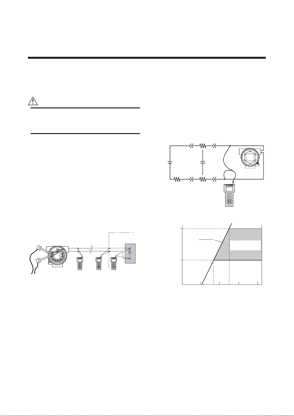
As shown in Figure 2.1, there are two methods of
connecting the transmitter and the BT200: the first is to
use the BT200 connection hook provided in the
terminal box and the other is to use a terminal board or
relay terminals on the transmission line.
Load impedance : 3.3 mH or less
Communication distance: 2 km (1.25 mile), when
CEV cable is used
Distance from the power line:
Output signal line : 15 cm (5.9 inch) or more
(do not use parallel wiring)
Input signal line : 100 cm (39.8 inch) or more
(do not use parallel wiring)
Input impedance of receiver connected to receiving
resistor: 10 kΩ more (at 2.4 kHz)
Rc
Power
supply
Figure 2.2 Communication line requirements
cc
YTA
RcR
BT200
F0202.EPS
4 to 20 mA DC
signal
Relay
terminals
YTA
BT200
Figure 2.1 Connecting the BT200
transmission
line
Control room
Terminal
board
Distributor
BT200BT200BT200
F0201.EPS
2.2 Communication Line Re-
quirements
Configure a loop that satisfies the following conditions
for mutual communication with the temperature
transmitter.
Power supply voltage : 16.4 to 42 V DC
Load resistance : R + 2Rc = 250 to 600 Ω
(See Figure 2.3 for the relationship between the
power supply voltage and load resistance.)
Load capacity : 0.22 µF or less
600
E–10.5
R=
Load
resistance
R
250
(Ω)
Figure 2.3 Relationship between power supply voltage
and load resistance
0.0236
10.5 16.4 24.7 42
Power supply voltage E (V)
Communication
applicable range
F0203.EPS
2-1
IM 01C50T03-01E
Page 8

3. OPERATION
IMPORTANT
Do not turn off the power to the transmitter
immediately after setting the data using the
BT200. If the transmitter is turned off less than
30 seconds after parameters have been set, the
setting data will not be stored in the transmitter.
3.1 Parameters Description
The following outlines the function of the BRAIN
parameters for the YTA.
• Sensor configuration See Page 3-4
When changing the sensor type from the current
setting to another, it is necessary to change parameter settings.
D10: SENSOR1 TYPE
D20: SENSOR1 WIRE
E10: SENSOR2 TYPE(YTA320 only)
E20: SENSOR2 WIRE(YTA320 only)
•Process variable mapping See Page 3-5
Process variables can be assigned as the primary
variable(PV), the secondary variable(SV), the
tertiary variable(TV), and the quaternary
variable(4V).
The following items can be mapped as the process
variables.
Sensor1, Sensor2*2, DIFFERENCE*2, AVERAGE*2,
Sensor1-Term, Sensor2-Term*2, Terminal Temp (*2:
These items are displayed for the model YTA320 only.)
B10: PV is, B20: SV is, B30: TV is, B40: 4V is
• Unit setting See Page 3-6
Choose the engineering unit for the process
variables assigned as the PV, SV, TV, and 4V from
degree C and Kelvin. When mV or ohm is specified
as an input type, the unit is automatically set to mV
or ohm.
B11: PV UNIT, B21: SV UNIT, B31: TV UNIT, B41: 4V
UNIT
• Range setting See Page 3-6
Changing the range of the PV as a 4 to 20mA DC
output. There are two ways to set the range value.
F10: LRV , F20: URV
F30: AUTO LRV , F35: AUTO URV
.............
.............
.......................
.........................
Sensor type setting
Wire connections setting
Setting by keypad
.
Setting by applying value
3. OPERATION
•
Damping time constant setting
See Page 3-6
Setting the response time of the transmitter smooths
the output with rapid changes in input.
The damping time constant can be set between 1
and 99 seconds.
B12: PV DAMPING, B22: SV DAMPING, B32: TV
DAMPING, B42: 4V DAMPING
• Tag Number, Memo, Description and Date
See Page 3-6
C10: TAG NO. ............... Tag number (16 characters)
O10: MEMO1, O20: MEMO2
...... MEMO (16 characters)
O30: DESCRIPTOR ...... DESCRIPTION (16 characters)
O40: DATE ..................... DATE (6 characters)
• Forced Output Function
(Manual Output mode) See Page 3-7
Setting the transmitter to output a fixed current
from -2.5 to 110 % in 0.1% increments for loop
checks.
G10: OUTPUT MODE, G20: OUPUT VALUE
•Integral Indicator Display Function
See Page 3-7
The input and output values can be displayed, as
can the type of temperature sensor and the number
of wire connections.
M10: PROCESS DISP ...... Process variable display
selection
M20: %/mA DISP ................ Output display selection
M30: MATRIX DISP ............ Sensor type/wire connec-
tions display selection
M40: BAR GRAPH ..............Output bar graph display
setting
M50: DISP UPDATE ........... Selection of a cycle speed
for display
M55: Err- NO DISP ............. Error code display
• Burn Out Function See Page 3-10
Configure the current output value in sensor failure.
Selectable from High, Low, and User setting
values.
F40: BURN OUT, F41: BURN OUT VAL, F50: TX
FAILURE
• Reverse Output Function See Page 3-10
To reverse the direction for a 4 to 20 mA DC
output relative to input.
H10: REVERSE OUT
3-1
IM 01C50T03-01E
Page 9

• Sensor Backup Function (YTA320 only)
See Page 3-10
Configure the transmitter to automatically transfer
the input from Sensor1 to Sensor2 when Sensor1
fails.
H20: SNSR BACKUP, H21: RETURN SNS1
• Copy the Setting Data to the BT200
See Page 3-11
Copy the setting data of one temperature transmitter
to another via the BT200. (Uploading & Downloading)
H30: UPLOAD SELCT
•Write Protect See Page 3-11
Configure the transmitter to enable/disable write
protection parameters
H40: WRITE PROTCT
•Sensor Trim See Page 3-12
Adjust the integral characterization curve stored in
memory.
J05: SNSR1 CLR, J10: SNSR1 ZERO, J20: SNSR1
GAIN ..... Sensor1 Trim
K05: SNSR2 CLR, K10: SNSR2 ZERO, K20: SNSR2
GAIN ... Sensor2 Trim (YTA320 only)
J07: IN TRIM MODE
3. OPERATION
• Output Trim See Page 3-13
Used for fine adjustment of a 4 to 20 mA DC
output.
L05: OUT CLR, J10: OUTPUT MODE, J20: OUT ZERO,
J30: OUT GAIN
• Error Messages See Page 4-1
To show that the transmitter has malfunctioned.
A60: SELF CHECK
• Warnings See Page 4-3
To show that incorrect settings entered for a
particular usage of the transmitter.
I59: WARNING, H50: WARNING ENBL
• Logging Function See Page 4-5
Store the errors and min/max process values.
3-2
IM 01C50T03-01E
Page 10

Menu tree for YTA110 & YTA310
3. OPERATION
HOME
A:VARIABLE
B:SET VAR CON.
Menu tree for YTA320
HOME
A:VARIABLE
B:SET VAR CON.
A10:PV
A11:mA of RANGE
A12:% of RANGE
A20:SV
A30:TV
A40:4V
A50: TERM
A60:SELF CHECK
B10:PV is
B11:PV UNIT
B12:PV DAMPING
B13:PV DMP POINT
B20:SV is
B21:SV UNIT
B22:SV DAMPING
B30:TV is
B31:TV UNIT
B32:TV DAMPING
B40:4V is
B41:4V UNIT
B42:4V DAMPING
B51:TERM UNIT
B60:SELF CHECK
A10:PV
A11:mA of RANGE
A12:% of RANGE
A20:SV
A30:TV
A40:4V
A50: TERM
A60:SELF CHECK
B05:SET DIFF
B10:PV is
B11:PV UNIT
B12:PV DAMPING
B13:PV DMP POINT
B20:SV is
B21:SV UNIT
B22:SV DAMPING
B30:TV is
B31:TV UNIT
B32:TV DAMPING
B40:4V is
B41:4V UNIT
B42:4V DAMPING
B51:TERM UNIT
B60:SELF CHECK
SET
C:SET TA G
D:SET SENSOR1
F:SET OUTPUT
G:FORCED OUT
H:SET MODE
I:INFORMATION
SET
C:SET TA G
D:SET SENSOR1
E:SET SENSOR2
F:SET OUTPUT
G:FORCED OUT
H:SET MODE
I:INFORMATION
C10:TAG NO.
C60:SELF CHECK
D10:SENSOR1 TYPE
D20:SENSOR1 WIRE
D40:SENSOR1
D41:SNSR1 UNIT
D60:SELF CHECK
F10:LRV
F20:URV
F30:AUTO LRV
F35:AUTO URV
F40:BURN OUT
F41:BURN OUT VAL
F50:TX FAILURE
F60:SELF CHECK
G10:OUTPUT MODE
G20:OUTPUT VALUE
G60:SELF CHECK
H01:CJC SELECT
H02: CNST CJC TMP
H10:REVERSE OUT
H30:UPLOAD SELCT
H40:WRITE PROTCT
H50:WARNING ENBL
H60:SELF CHECK
I10:PV LRL
I11:PV URL
I12:PV MIN SPAN
I20:SNSR1 LSL
I21:SNSR1 USL
I40:TERM LSL
I41:TERM USL
I59:WARNING
I60:SELF CHECK
C10:TAG NO.
C60:SELF CHECK
D10:SENSOR1 TYPE
D20:SENSOR1 WIRE
D40:SENSOR1
D41:SNSR1 UNIT
D60:SELF CHECK
E10:SENSOR2 TYPE
E20:SENSOR2 WIRE
E40:SENSOR2 TEMP
E41:SNSR2 UNIT
E60:SELF CHECK
F10:LRV
F20:URV
F30:AUTO LRV
F35:AUTO URV
F40:BURN OUT
F41:BURN OUT VAL
F50:TX FAILURE
F60:SELF CHECK
G10:OUTPUT MODE
G20:OUTPUT VALUE
G60:SELF CHECK
H01:CJC SELECT
H02: CNST CJC TMP
H10:REVERSE OUT
H20:SNSR BACKUP
H21:RETURN SNSR1
H30:UPLOAD SELCT
H40:WRITE PROTCT
H50:WARNING ENBL
H60:SELF CHECK
I10:PV LRL
I11:PV URL
I12:PV MIN SPAN
I20:SNSR1 LSL
I21:SNSR1 USL
I30:SNSR2 LSL
I31:SNSR2 USL
I40:TERM LSL
I41:TERM USL
I59:WARNING
I60:SELF CHECK
ADJ
J:CAL SENSOR1
L:CAL OUTPUT
M:SET METER
O:MEMO
P:RECORDS
ADJ
J:CAL SENSOR1
K:CAL SENSOR2
L:CAL OUTPUT
M:SET METER
O:MEMO
P:RECORDS
J05:SNSR1 CLR
J07:IN TRIM MODE
J10:SNSR1 ZERO
J20:SNSR1 GAIN
J30:SNSR1 SERIAL
J60:SELF CHECK
L05:OUT CLR
L10:OUTPUT MODE
L20:OUT ZERO
L30:OUT GAIN
L60:SELF CHECK
M10:PROCESS DISP
M20:%/mA DISP
M30:MATRIX DISP
M40:BAR GRAPH
M50:DISP UPDATE
M55:Err-NO DISP
M60:SELF CHECK
O10:MEMO1
O20:MEMO2
O30:DESCRIPTOR
O40:DATE
O60:SELF CHECK
P05:LOG CLEAR
P10:PV MIN LOG
P11:PV MAX LOG
P12:SV MIN LOG
P13:SV MAX LOG
P14:TV MIN LOG
P15:TV MAX LOG
P16:4V MIN LOG
P17:4V MAX LOG
P18:TERM MIN LOG
P19:TERM MAX LOG
P20:ERR LOG 1
P21:ERR LOG 2
P22:ERR LOG 3
P23:ERR LOG 4
P24:ERR LOG CLR
P30:OPERATE TIME
P31:POWER CHECK
P40:BCC ERROR %
P60:SELF CHECK
J05:SNSR1 CLR
J07:IN TRIM MODE
J10:SNSR1 ZERO
J20:SNSR1 GAIN
J30:SNSR1 SERIAL
J60:SELF CHECK
K05:SNSR2 CAL CLR
K10:SNSR2 ZERO
K20:SNSR2 GAIN
K30:SNSR2 SERIAL
K60:SELF CHECK
L05:OUT CLR
L10:OUTPUT MODE
L20:OUT ZERO
L30:OUT GAIN
L60:SELF CHECK
M10:PROCESS DISP
M20:%/mA DISP
M30:MATRIX DISP
M40:BAR GRAPH
M50:DISP UPDATE
M55:Err-NO DISP
M60:SELF CHECK
O10:MEMO1
O20:MEMO2
O30:DESCRIPTOR
O40:DATE
O60:SELF CHECK
P05:LOG CLEAR
P10:PV MIN LOG
P11:PV MAX LOG
P12:SV MIN LOG
P13:SV MAX LOG
P14:TV MIN LOG
P15:TV MAX LOG
P16:4V MIN LOG
P17:4V MAX LOG
P18:TERM MIN LOG
P19:TERM MAX LOG
P20:ERR LOG 1
P21:ERR LOG 2
P22:ERR LOG 3
P23:ERR LOG 4
P24:ERR LOG CLR
P30:OPERATE TIME
P31:POWER CHECK
P40:BCC ERROR %
P60:SELF CHECK
F0300.EPS
3-3
IM 01C50T03-01E
Page 11
3. OPERATION
3.2 Setting Parameters
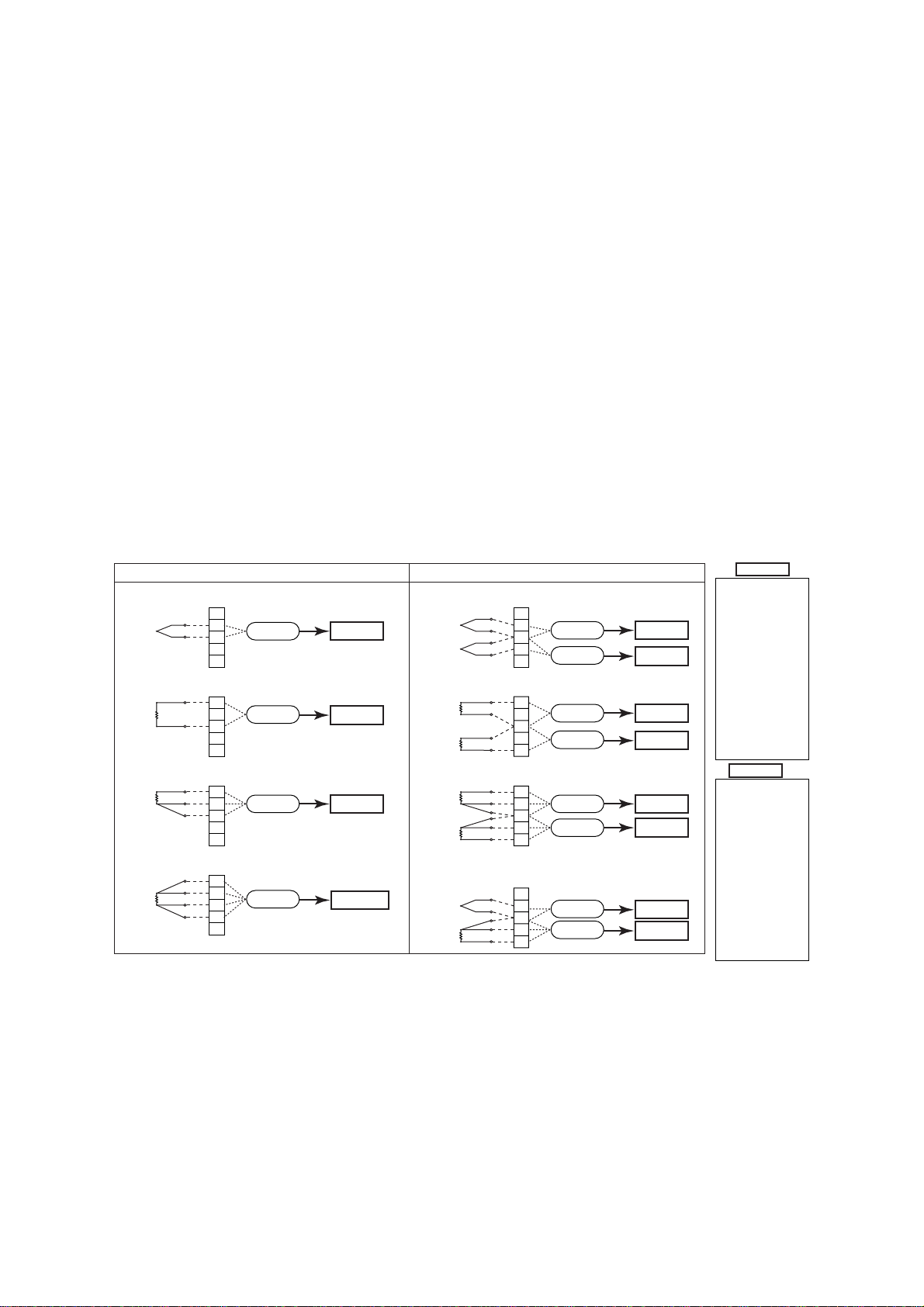
3.2.1 Sensor Configuration
When the sensor type or the number of wire connections changes, the following parameters must be reset.
Sensor type setting;
D10: SENSOR1 TYPE, E10: SENSOR2 TYPE
Wire connections setting;
D20: SENSOR1 WIRE, E20: SENSOR2 WIRE
Figure 3.1 diagram shows the wire connections to the
input terminals of the transmitter and sensor type
selections for the parameters in each connection case.
Note that TCs and mV are categorized as Group A and
RTDs and ohm as Group B.
Check the connections between the input terminals and
temperature sensors and set the correct sensor type and
the number of wire connections for the parameters.
Sensor type selection
Thermocouple TYPE W3, W5 (ASTM988)
TYPE B, E, J, K, N, R, S, T
(IEC 584)
TYPE L, U (DIN 43710)
Resistance thermometer
Pt100, Pt200, Pt500
(IEC 751)
[2-, 3- or 4-wire] JPt100 (JIS)
Ni120 (STI INC), Cu
(SAMA RC21-4)
DC voltage mV
Resistance ohm [2- or 3-wire]
1-input model YTA110, YTA310, and YTA320
Thermocouple and DC voltage (TC & mV)
1
(+)
2
Sensor1
3
(–)
4
5
Resistance thermometer(RTD) and resistance (2-wire type)
Resistance thermometer(RTD) and resistance (3-wire type)
Resistance thermometer(RTD) (4-wire type)
(A)
1
Sensor1
2
(B)
3
4
5
(A)
1
(B)
(B)
(A)
(A)
(B)
(B)
Sensor1
2
3
4
5
1
2
Sensor1
3
4
5
Group A
Group B
Group B
Group B
* : Without ohm
Thermocouple and DC voltage (TC & mV)
Resistance thermometer(RTD) and resistance (2-wire type)
Resistance thermometer(RTD) and resistance (3-wire type)
Thermocouple(TC) &
Resistance thermometer(RTD) and resistance (3-wire type)
*
2-input model YTA320
(+)
1
2
(–)
3
4
(+)
5
(A1)
1
(B1)
2
3
(B2)
4
(A2)
5
(A1)
1
(B1)
2
(B1)
3
(B2)
4
(B2)
5
(A2)
(+)
1
(–)
2
(B)
3
4
(B)
5
(A)
Figure 3.1 Input terminal wire connection diagram and sensor type categories
Sensor1
Sensor2
Sensor1
Sensor2
Sensor1
Sensor2
Sensor1
Sensor2
Group A
Group A
Group B
Group B
Group B
Group B
Group A
Group B
Group A
TYPE B (IEC584)
TYPE W3 (ASTM988)
TYPE W5 (ASTM988)
TYPE E (IEC584)
TYPE J (IEC584
TYPE K (IEC584)
TYPE L (DIN43710)
TYPE N (IEC584)
TYPE R (IEC584)
TYPE S (IEC584)
TYPE T (IEC584)
TYPE U (DIN43710)
Pt100 (IEC751)
Pt200 (IEC751)
Pt500 (IEC751)
JPt100 (JIS)
Ni120 (STI INC)
Cu (SAMA RC21-4)
ohm
mV
Group B
TYPE B (IEC584)
TYPE W3 (ASTM988)
TYPE W5 (ASTM988)
TYPE E (IEC584)
TYPE J (IEC584
TYPE K (IEC584)
TYPE L (DIN43710)
TYPE N (IEC584)
TYPE R (IEC584)
TYPE S (IEC584)
TYPE T (IEC584)
TYPE U (DIN43710)
Pt100 (IEC751)
Pt200 (IEC751)
Pt500 (IEC751)
JPt100 (JIS)
Ni120 (STI INC)
Cu (SAMA RC21-4)
* Only for 2 or 3-wire type]
ohm [
mV
F0301.EPS
3-4
IM 01C50T03-01E
Page 12

3. OPERATION
● Example: Set Pt 100 and 4-wire type to Sensor1.
(model YTA320)
<1>
PARAM
D10:SENSOR1 TYPE
Pt200 (IEC751)
D20:SENSOR WIRE
3 WIRE
D40:SENSOR1 TEMP
23.56 degC
DATA DIAG PRNT ESC
<2>
SET
D10:SENSOR1 TYPE
Pt200 (IEC751)
<Pt100 (IEC751) >
<Pt200 (IEC751) >
<Pt500 (IEC751) >
<JPt100 (JIS ) >
<3>
SET
D20:SENSOR1 WIRE
3 WIRE
<3 WIRE >
<4 WIRE >
<2 WIRE >
TYPE B (IEC584)
TYPE W3(ASTM988)
TYPE W5(ASTM988)
TYPE E (IEC584)
TYPE J (IEC584)
TYPE K (IEC584)
TYPE L(DIN43710)
TYPE N (IEC584)
TYPE R (IEC584)
TYPE S (IEC584)
TYPE T (IEC584)
TYPE U(DIN43710)
Pt100 (IEC751)
Pt200 (IEC751)
Pt500 (IEC751)
JPt100 (JIS)
Ni120 (STI INC)
Cu (SAMA RC21-4)
ohm
mV
Non Connection
1. Select D: SET SENSOR1 to go
to the screen (1).
2. Select “D10” and press
[ENTER] to go to the
screen (2).
3. Select “Pt100” and press
[ENTER] twice.
4. Check that “Pt100” has been
set and press [OK].
ESC
5. To set the number of wire
connections, select
D20 and press [ENTER].
6. Select “4 WIRE” and press
ESC
[ENTER] twice.
7. Press [OK].
Note: D40 indicates input values of
the sensor based on the
settings at D10 and D20.
F0302.EPS
3.2.2 Process Variables Mapping
Process variable mapping;
B10: PV is, B20: SV is, B30: TV is, B40: 4V is
Process variables can be assigned as the primary
variable(PV), the secondary variable(SV), the tertiary
variable(TV), and the quaternary variable(4V). The PV
always outputs a 4 to 20mA DC analog signal corresponding to Lower Range Value and Upper Range
Value. Mapping process variables to the SV, TV, and
4V is optional.
The following items can be mapped as the process
variables.
Sensor1 : Sensor1 input value.
Sensor2 : Sensor2 input value.
DIFFERENCE
*1,*2,*4
: Difference between
Sensor1 and Sensor2.
(Sensor1-Sensor2 or
Sensor2-Sensor1; specified in B05: SET DIFF)
AVERAGE
*1,*4
: Average of Sensor1 and
Sensor2.
[(Sensor1 + Sensor2)/2]
Sensor1-Term
*4,*5
: Difference between
Sensor1 and terminal
temperature
Sensor2-Term
*1,*4,*5
: Difference between
Sensor2 and terminal
temperature
Terminal Temp : Terminal temperature
Not used
*3
: Showing that a process
variable is not assigned.
*1: This item is displayed only when the YTA320 2-input
temperature transmitter is used.
*2: The setting in B05 applies to the PV, SV, TV, and 4V.
*3: “Not used” is not displayed for B10 since the PV
requires process variable mapping.
*4: When this item is selected, the sensor types to be set
for D10(Sensor1) and E10(Sensor2) should be
selected from any one of the following three groups;
Temperature sensor(T/C and RTD), DC voltage or
resistance. The combination(for example, temperature
sensor and DC voltage input) would cause an incorrect
computation due to the different unit system and is not
allowed.
*5: When this item is selected, DC voltage and resistance
input should not be set for D10(Sensor1) or
E10(Sensor2).
● Example: Use two temperature sensors to map the
difference (Sensor2-Sensor1) between Sensor1
and Sensor2 to the PV (the primary variable).
Before mapping the process variable, complete the
setting of the temperature sensor to be connected
to Sensor1 and Sensor2.
Sensor1 setting: D10: SENSOR1 TYPE, D20:
SENSOR1 WIRE
Sensor2 setting: E10: SENSOR2 TYPE, E20:
SENSOR2 WIRE
PARAM
B05:SET DIFF
Sensor1-Sensor2
B10:PV is
Sensor1
B11:PV UNIT
degC
DATA DIAG PRNT ESC
SET
B05:SET DIFF
Sensor1-Sensor2
<Sensor1-Sensor2 >
<Sensor2-Sensor1 >
SET
B10:PV is
Sensor1
<Sensor1 >
<Sensor2 >
<DIFFERENCE >
<AVERAGE >
If the temperature sensor is correctly connected to Sensor1
and Sensor2,
the setting content is reflected on A10: PV.
1. Set the content of
“DIFFERENCE” for the
difference between Sensor1
and Sensor2.
Select B05: SET DIFF and
press [ENTER]
2. Select “Sensor2 - Sensor1” and
press [ENTER] twice.
3. Press [OK].
ESC
4. Select B10: PV is and press
[ENTER] for PV mapping.
5. Select “DIFFERENCE” and
ESC
press [ENTER] twice.
6. Press [OK].
F0303.EPS
3-5
IM 01C50T03-01E
Page 13
3. OPERATION
3.2.3 Unit Setting
B11: PV UNIT, B21: SV UNIT, B31: TV UNIT, B41: 4V
UNIT
Select the engineering unit for the process variables
assigned as PV, SV, TV, and 4V from degree C,
Kelvin, degree F* and degree R*. When mV or ohm is
specified as an input type, the unit is automatically set
to mV or ohms.
*: Degree F and degree R are available only when
optional code /D2 is specified.
3.2.4 Range Setting
(a) Changing the range with keypad
Lower range value setting;
F10: LRV, Upper range value setting; F20: URV
The range for the PV corresponding to the 4 to 20mA
output signal is set at the factory before shipment. The
procedure to rerange is as follows.
● Example: Changing the measurement range from
0 to 100°C to 0 to 150°C .
PARAM
F10:LRV
0 degC
F20:URV
100 degC
F30:AUTO LRV
DISABLE
DATA DIAG PRNT ESC
PARAM
F20:URV
0 degC
+ 150
DEL CLR ESC
Note : The unit selected in B11: PV UNIT is applied to the units used
for F10 and F20.
NOTE
When entering numeric values at the range
setting, the value of URV must be greater than
that of LRV.
Range Setting Condition: URV > LRV
1. Select F20: URV and press
[ENTER].
2. Input “150” and press [ENTER]
twice.
3. Press [OK].
F0304.EPS
3.2.5 Setting Damping Time Constant
B12: PV DAMPING, B22: SV DAMPING,
B32: TV DAMPING, B42: 4V DAMPING
Setting the response time of each Process Variable to
make the output change very slowly with a rapid
change in input. Set the value from 0 to 99 seconds.
If the time constant is set to 2 seconds, the transmitter
calculates a reading every cycle using the damping
equation, in order to make the output 63 percent of the
input range after 2 seconds.
This damping time constant is normally set to work
when the temperature make a step change within 2
percent of the output range. The damping can be
changed using the “B13: PV DMP POINT” parameter.
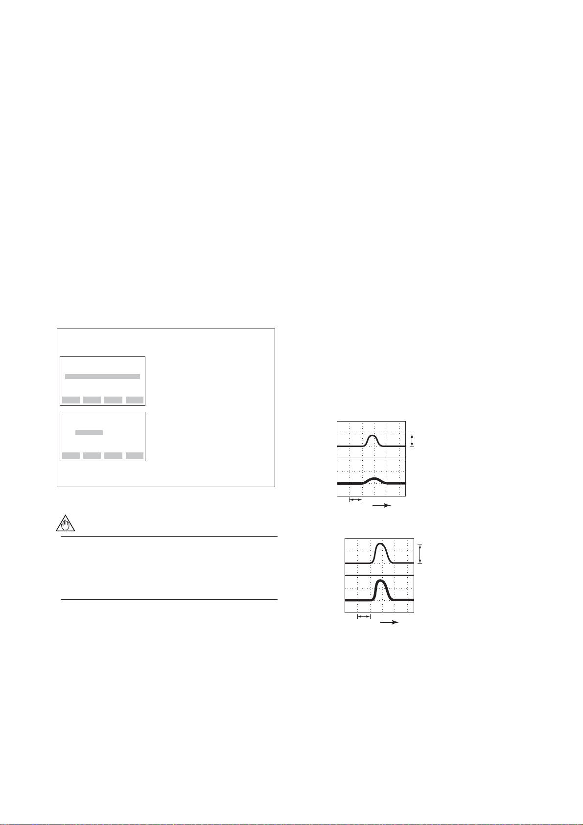
● Setting Damping Holding Point
B13: PV DMP POINT
This parameter is used to set the point where the
transmitter conducts the PV damping operation,
depending on a magnitude of the change in the
input value. When the change value in percent
exceeds the setting value, the transmitter outputs
the signal without the damping operation.
Set the value as a percent of span.
● Example: Output pattern for the setting value of 10%
•Change value less then 10%
(C)
Input
10
0
(%)
Output
10
0
3 sec.
•Change value 10% or above
(C)
Input
10
0
(%)
Output
10
0
Time
9%
Assumed setting
Renge: 0 to 100 C
Damping time: 3 sec.
14%
(b) Changing the range while applying an
actual input
F30: AUTO LRV
F35: AUTO URV
This feature allows the lower and upper range values to
be setup automatically with the actual input applied.
3 sec.
Time
3.2.6 Tag Number and Memo Writing
Tag number (See Appendix A. Section A.3.2)
C10: TAG NO.
Up to sixteen alphanumeric characters can be entered.
The tag number is as specified upon shipment.
3-6
IM 01C50T03-01E
F0325.EPS
Page 14
3. OPERATION
Memo
O10: MEMO1, O20: MEMO2
Up to sixteen alphanumeric characters can be entered.
Description
O30: DESCRIPTOR
Up to sixteen alphanumeric characters can be entered.
Date
O40: DATE
Six numeric values can be entered. Only a date
recording function is provided; no internal clock
function is provided, thus the date is not updated.
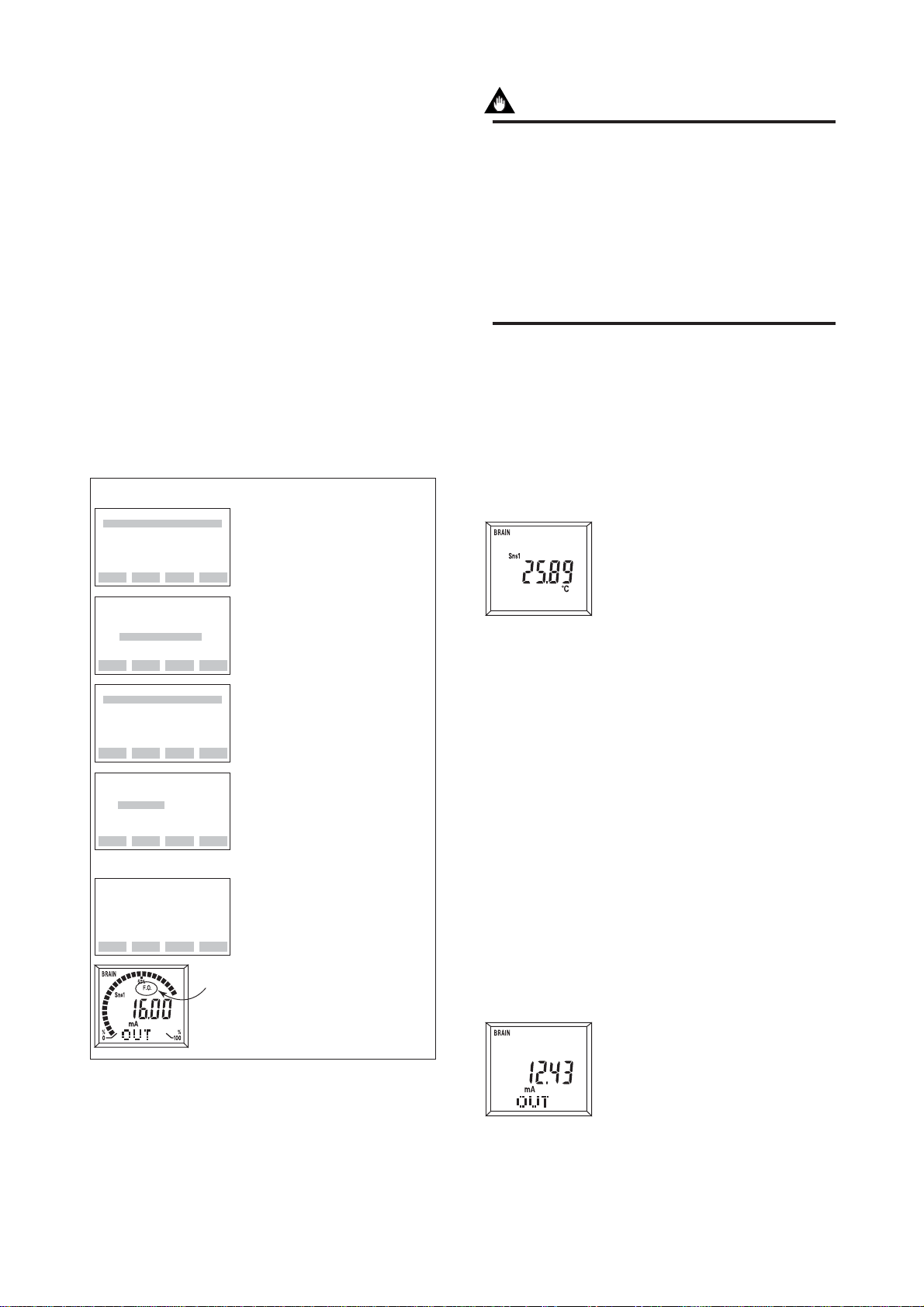
3.2.7 Forced Output Function
G10: OUTPUT MODE, G20: OUPUT VALUE
This feature can be used to output a fixed current from
3.6 mA (-2.5%) to 21.6 mA (110%) for loop checks.
● Example: Outputting 16 mA (75%) constant current
PARAM
G10:OUTPUT MODE
AUTOMATIC MODE
G60:SELF CHECK
GOOD
DATA DIAG PRNT ESC
SET
G10:OUTPUT MODE
AUTOMATIC MODE
<AUTOMATIC MODE >
<MANUAL MODE mA >
<MANUAL MODE % >
PARAM
G10:OUTPUT MODE
MANUAL MODE mA
G20:OUTPUT VALUE
4 mA
C60:SELF CHECK
GOOD
DATA DIAG PRNT ESC
SET
G20:OUTPUT VALUE
4 mA
+ 16
DEL CLR ESC
SET
G20:OUTPUT VALUE
16 mA
FEED NO OK
1. Select G10: OUTPUT MODE
and press [ENTER].
2. Set "MANUAL MODE mA."
ESC
3. G20: OUTPUT VALUE is
displayed.
Select G20: OUTPUT VALUE
and press [ENTER].
4. Set "16."
5. Pressing [ENTER] twice outputs
a constant current.
If the transmitter is equipped
with the integral indicator, the
LCD displays F.O.
6. Press [OK].
IMPORTANT
• Manual mode output is held for approximately
10 minutes and then released automatically
after the time has elapsed. Even if the BT200
power supply is turned off or the communication connector is disconnected during the test,
it is held for approximately 10 minutes.
• To release the test output immediately, set
“AUTOMATIC MODE” at G10 as seen in the
figure above or turn off the transmitter.
3.2.8 Integral Indicator Display Function
If the transmitter is equipped with the integral indicator, the following items can be displayed in parameter
settings.
(a) Display process variable
M10: PROCESS DISP
Displays PV value.
Also, if the output value is selected at M20, the process
variable and output value are displayed alternately.
PV : Displays PV value
SV : Displays SV value
TV : Displays TV value
4V : Displays 4V value
PV, SV : Displays PV and SV
PV, SV, TV : Displays PV, SV and TV
PV, SV, TV, 4V : Displays PV, SV, TV, and
INHIBIT : The process variable is
Used to select the process variable
to be displayed on the LCD
indicator. If more than one process
is selected, they are displayed in
sequence as the display update
cycles. The appropriate unit is also
F03291
displayed for each process variable.
value alternately
value alternately
4V value alternately
not displayed.
"F.O." lit on.
F0305.EPS
(b) Display output value
M20: %/mA DISP
Displays output value.
Used to select the output indications to be displayed on the LCD
indicator. If two output indications
are selected, they are displayed in
sequence as the display update
cycles.
F03292
3-7
IM 01C50T03-01E
Page 15

3. OPERATION
mA : Displays output value in mA
%: Displays output value in %
mA, % : Displays output value in
mA and % alternately
INHIBIT : The output value is not
displayed
(c) Display sensor type/number of wire
connections
M30: MATRIX DISP
Displays PV value and
sensor type
Used to select the input sensor type
and the number of wire connections to be displayed on the LCD
indicator. The displays of these
items are synchronized with the
process variable displays selected
F03293
at M10. Specifying “INHIBIT”
under M10 disables the function of M30 for the
display.
PROCESS : Displays process variables
(PV, SV, TV, or 4V.)
TYPE : Displays sensor type
WIRE : Displays number of wire
connections
PROCESS, TYPE : Displays process and
sensor type alternately
TYPE, WIRE : Displays sensor type and
number of wire
connections alternately
INHIBIT : the sensor type and the
number of wire
connections is not
displayed
FAST : 1/2 of the normal cycle
speed
NORMAL : Normal cycle speed
SLOW : 1.5 times of the normal
cycle speed
NOTE
When operating under –10°C(14°F), the display
response time may be reduced. In such a case,
set the display cycle speed to “NORMAL” or
“SLOW.”
(d) Display output bar graph
M40: BAR GRAPH
Displays bar graph.
Used to select output bar graph
display ON/OFF.
F03292
SHOW : Displays analog output bar
graph
INHIBIT : No bar graph display
(e) Select a cycle speed for display
M50: DISP UPDATE
Used to select the update rate for the display on the
LCD indicator. Process variables, output values, and
error codes are displayed using this cycle speed.
3-8
IM 01C50T03-01E
Page 16

(f) Display error code
M55: Err-NO DISP
If an error occurs, the error code is displayed on the
LCD indicator.
SHOW : Error code is displayed
INHIBIT : Error code is not displayed
●Example of LCD display cycle
The example of the LCD indicator is based on the following settings.
3. OPERATION
Integral indicator display parameter setting
M10: PROCESS DISP = PV, SV
M20: %/mA DISP = mA
M30: MATRIX DISP = PROCESS, TYPE
M40: BAR GRAPH = SHOW
Process variable display PV value PV value SV value SV value
%/mA display: mA
Matorix display: Process variable Sensor type Process variable Sensor type
Bar graph ON
Assumed current status and parameter settings
A10: PV = 50.0 degC
A11: mA of RANGE = 12.00 mA
A20: SV = 25.16 degC
B10: PV is = Sensor1
B20: SV is = Sensor1-Term
D10: SENSOR1 TYPE = TYPE B
F0306.EPS
3-9
IM 01C50T03-01E
Page 17
3.2.9 Burn Out Function
(a) Sensor burn out
Configure the burn out mode in the case of sensor
failure or disconnection. When the sensor failure is
detected, the transmitter will output one of the following values.
F40: BURN OUT
Select from the followings:
LOW : Outputs 3.6 mA (-2.5%)
HIGH : Outputs 21.6 mA (110%)
USER mA : Output user set value in mA.
Settable 3.6 to 21.6 mA in F41
USER % : Output user set value in %.
Settable -2.5 to 110 % in F41
OFF : The burn out output is NOT
defined
F41: BURN OUT VAL
When “USER mA” or “USER %” is selected at
F40:BURN OUT, F41:BURN OUT VAL is displayed.
The output value setting range is 3.6 to 21.6 mA (-2.5
to 110%).
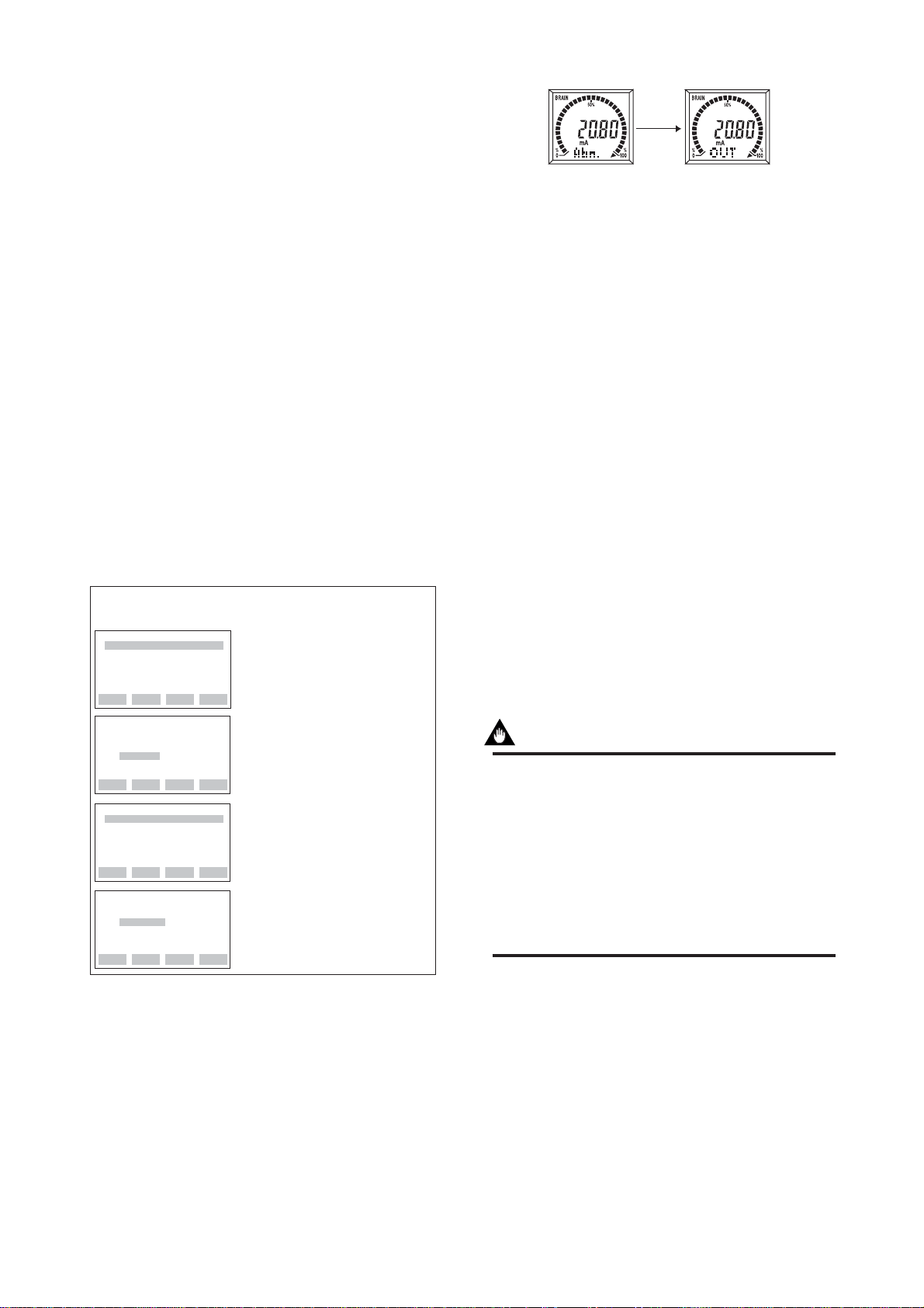
3. OPERATION
Displays "Abn." Displays "OUT."
F0308.EPS
Figure 3.2 Integral Indicator Display in Sensor Burn Out
(b) Confirming the output direction if Hard-
ware error occurs
F50: TX FAILURE
The output status of the transmitter in hardware failure
is set by using a jumper on the CPU assembly. (See IM
01C50B01-01E section 3.2) The current setting can be
checked in parameter D50: TX FAILURE.
HIGH : When an error occurs,
110%(21.6mA) or higher is
output.
LOW : When an error occurs,
-5%(3.2mA) or lower is output.
3.2.10 Reverse Output Function
● Example: Setting output to 20.8 mA in the event of
sensor burn out
PARAM
F40:BURN OUT
HIGH
F50:TX FAILURE
HIGH
F60:SELF CHECK
GOOD
DIAG PRNT ESC
DATA
SET
F40:BURN OUT
HIGH
<HIGH >
<USER mA >
<USER % >
<OFF >
PARAM
F40:BURN OUT
USER mA
F41:BURN OUT VAL
21.6 mA
F50:TX FAILURE
HIGH
DIAG PRNT ESC
DATA
SET
F41:BURN OUT VAL
21.6 mA
+ 20.8
DEL CLR ESC
1. Select F40: BURN OUT and
press [ENTER].
2. Select "USER mA" and press
[ENTER] twice.
3. Press [OK].
ESC
4. Select F40: BURN OUT VAL
and press [ENTER].
5. Set “20.8” and press [ENTER]
twice.
6. Press [OK].
F0307.EPS
During sensor burn out time, the Sensor1 failure or the
Sensor2 failure error message is generated. (See
Section 4.1.1 for details.)
If the transmitter is equipped with the integral indicator, the LCD displays “Abn.” and “OUT” as shown in
Figure 3.2.
H10: REVERSE OUT
To reverse the direction for a 4 to 20 mA DC output
relative to input.
3.2.11 Sensor Backup Function (For Model YTA320)
IMPORTANT
To use sensor backup function, the following
conditions must be met.
• “Sensor1” is mapped as the PV at B10: PV is.
• “Sensor2” is mapped as the SV at B20: SV is.
• “Sensor1” and “Sensor2” are both correct
input status.
• “HIGH, LOW, User mA, or User %” is selected in the sensor burnout
parameter setting at F40: BURN OUT
The sensor backup command sets the transmitter to
automatically use Sensor2 as PV if Sensor1 fails.
When the transmitter is in the Sensor Backup operation
and switches to Sensor2, there will be no disruption in
the 4 to 20 mA output. The error code for Sensor1
failure is shown on the integral indicator, and also the
error message is sent to the BT200 that the Sensor1
failed and the sensor backup has been in operation. In
case Sensor2 fails during the backup operation, the
3-10
IM 01C50T03-01E
Page 18

3. OPERATION
transmitter will send the error code for Sensor2 failure
to the integral indicator and the BT200, and outputs the
“Sensor burnout” value.
(a) Setting of backup mode
H20: SNSR BACKUP
Set “ENABLE” at H20: SNSR BACKUP.
ENABLE : Activates backup mode, and
transmitter starts to observe.
DISABLE : Cancels backup mode.
IMPORTANT
Do not change the PV and SV mapping data
when the sensor backup mode is active. Cancel
the sensor backup mode to alter the mapping
data.
(b) Returning from Sensor2 to Sensor1 during
the sensor backup operation
H21: RETURN SNS1
Once the transmitter enters the sensor backup operation, H21:RETURN SNS1 appears on the BT200. This
parameter is used to retrieve the output to the Sensor1
input value. Ensure that Sensor1 and Sensor2 are both
correct input status, then;
Set “ENABLE” at H21:RETURN SNS1.
ENABLE : Switches to Sensor1 output.
DISABLE : Maintains Sensor2 output status.
SET PRAM ONLY : Uploads the parameters
with respect to the operation settings such as LRV
and the sensor type.
ALL PRAM : Uploads the all param-
eters.
See the parameter list at the end of this manual for
classification of the operation setting parameter groups
and the parameter group unique to the equipment. See
also the BT200 instruction manual, IM 1C0A11-01E,
for the setting procedure.
3.2.13 Write Protect Function
(a) Software Write Protect Function
H40: WRITE PROTCT
The write protect function is used to prevent unauthorized configuration data changes in the transmitter.
YES : Disables writing of all parameters
other than H40.
NO : Enables writing of all param-
eters.
If the transmitter is equipped with the integral indicator, the LCD displays “W.P.” when setting H40 to
YES.
● Example: Setting write protect on
SET
H40:WRIT PROTCT
NO
<NO >
<YES >
1. Select “YES” and press
[ENTER] twice to enter
the setting.
ESC
"W. P." lit on
IMPORTANT
In the sensor backup operation, even if the
Sensor1 recovers, the Sensor2 input value
continues to be output until “ENABLE” is set at
H21: RETURN SNS1 or the transmitter's power
is turned off and then on again.
3.2.12 Copy the Setting Data
H30: UPLOAD SELCT
This function is used to copy the setting data of one
temperature transmitter to another.
Connect the temperature transmitter with the BT200
and record (UPLOAD) the setting data to the BT200
nonvolatile memory. By connecting the BT200 to other
temperature transmitters, recorded data can be overwritten (DOWNLOAD) on the transmitters.
The YTA series temperature transmitter handles the
uploading data at two levels. It is necessary to specify
the desired one before uploading data.
(b) Hardware Write Protect Function
Hardware write protect function is set up by Switch
(SW2) on the CPU assembly. Under write protect
status, any change operation is denied. If the transmitter is equipped with the integral indicator, the LCD
displays “W.P.” when setting SW2 to “Y”.
3-11
IM 01C50T03-01E
F0309.EPS
Page 19

3. OPERATION
Pin position of SW2
W P
Y
SW2
N
W P
Y
SW2
N
SW1
Burnout output direction
upon hardware failure
CPU Assembly
Figure 3.3 SW2 setting
Write Protect Status
No
Yes
SW2
Hardware Write Protect
F0355.EPS
3.2.14 Sensor Trim
Each YTA transmitter is factory-characterized based on
the standard sensor curve and uses the information to
produce a process variable output. The sensor trim
function is used to adjust to the transmitters internal
interpretation of the input signal.
ZERO
Output
Input
One point trim
Figure 3.4 Trim function images
ZERO
Output
Input
Two points trim
(a) Zero/Gain Point Adjustment
J07: IN TRIM MODE
J10: SNSR1 ZERO, J20: SNSR1 GAIN
K10: SNSR2 ZERO, K20: SNSR2 GAIN ...YTA320 only
1) Connect the temperature transmitter and the
calibration device as shown in Figure 3.5 and warm
up for at least three minutes.
GAIN
F0310.EPS
a. Wiring of power supply and output
+ Output signal
–
Load resistance
Voltmeter
b. Example of wiring of thermocouple
or DC voltage input (1-input type)
1
2
3
4
5
c. Example of wiring of thermometer resistor
4-wire type (1-input type)
1
2
3
4
5
Figure 3.5 Example of wiring for calibration equipment
(+)
(–)
DC voltage generator
or thermocouple
(A)
(A)
(B)
(B)
Variable resistor
or thermometer resistor
F0311.EPS
2) Check the sensor type with the D: parameter.
3) Select the input trimming mode in J07:IN TRIM
MODE. The following selections are offered.
V.R./ZERO&GAIN
V.R./ZERO
TEMP/ZERO&GAIN
TEMP/ZERO
Select “V.R./ZERO&GAIN” or “V.R./ZERO” when
the calibration device is DC voltage generator or
Variable resistor, or select “TEMP/ZERO&GAIN”
or “TEMP/ZERO” when the device is Temperature
sensor.
4) Perform zero-point adjustment.
•When the input trimming mode is “V.R./
ZERO&GAIN” or “V.R./ZERO”, apply the value
for the zero-point shown in the Table 3.1 depending on the specified sensor type. Wait until the
input from the calibration device becomes stable.
•When the input trimming mode is “TEMP/
ZERO&GAIN” or “TEMP/ZERO”, expose the
temperature sensor to calibration temperature for
the zero-point. Wait until the input from the
temperature sensor becomes stable.
3-12
IM 01C50T03-01E
Page 20

3. OPERATION
Table 3.1 Zero and Gain point value for Sensor
trim
Sensor type
TC B,R,S,T +0[mV] +25[mV]
E,J,K,N,W3,W5,L,U, mV +0[mV] +75[mV]
RTD Pt100,JPt100,NI120,Cu +40[ohm] +330[ohm]
Pt200, Pt500, ohm +40[ohm] +1600[ohm]
Setting value
Zero-point Gain-point
T0301.EPS
5) Enter the current input value in J10: SNSR1 ZERO
(or K10: SNSR2 ZERO for YTA320).
6) Press [ENTER] twice and press [OK].
7) Perform gain-point adjustment if “V.R./
ZERO&GAIN” or “TEMP/ZERO&GAIN” is
selected in J07:IN TRIM MODE.
•When the input trimming mode is “V.R./
ZERO&GAIN” apply the value for the gain-point
shown in the Table 3.1 depending on the specified sensor type. Wait until the input from the
calibration device becomes stable.
•When the input trimming mode is “TEMP/
ZERO&GAIN”, expose the temperature sensor to
calibration temperature for the gain-point. Wait
until the input from the temperature sensor
becomes stable.
8) Enter the current input value in J20: SNSR1 GAIN
(or K20: SNSR2 GAIN for YTA320).
9) Press [ENTER] twice and press [OK].
NOTE
• First correct the ZERO point, then correct the
GAIN point in two points calibration. When the
GAIN point is adjusted, the ZERO point
correction amount is also updated and written
into the EEPROM.
• The calibration unit is changed to “mV” or
“ohm” depending on the type of connected
sensor when the input trimming mode is “V.R./
ZERO&GAIN” or “V.R./ZERO” or to temperature unit selected at D41:SNSR1 UNIT.
(b) Returning to the factory set value
J05: SNSR1 CLR
K05: SNSR2 CLR ...YTA320 only
To return to the factory set value, set “USER CAL
CLEAR” or “USER CAL IGNORE” at J05: SNSR1
CLR for the Sensor1 and K05: SNSR2 CLR for the
Sensor2.
USER CAL CLEAR : Clear user trim value
and return to the
factory set value.
USER CAL IGNORE : Ignore user trim value
and return to the
factory set value.
USER CAL ACT : Use user trim value.
NOTE
Regardless of restarting the transmitter, the
“USER CAL ACT” is always set and the user
trim value is used as the input signal unless it is
cleared by “USER CAL CLEAR.”
3.2.15 Output Trim
(a) Zero/Gain Point Adjustment
L10: OUTPUT MODE, L20: OUT ZERO, L30: OUT GAIN
The output adjustment function can match the 4 mA
and 20 mA output of the temperature transmitter to the
reference meter such as a voltmeter.
1) Connect the temperature transmitter, 250 Ω
resistance and the voltmeter as shown in Figure 3.2.
2) Select L10: OUTPUT MODE and press [OK].
3) Select “MANUAL MODE 4mA” and press
[ENTER] twice.
(4 mA output status continues for 10 minutes.)
Press [OK].
4) Select L20: OUT ZERO and press [OK].
5) Write the indicated value of the voltmeter to L20:
OUT ZERO and press [ENTER] twice.
(The temperature transmitter automatically corrects
the difference between this value and the operation
output.)
Press [OK].
6) Select L10: OUTPUT MODE and press [OK].
7) Select “MANUAL MODE 20mA” and press
[ENTER] twice.
(20 mA output status continues for 10 minutes.)
Press [OK].
8) Write the indicated value of the voltmeter at L30:
OUT GAIN and Press [ENTER] twice.
(The temperature transmitter automatically corrects
the difference between this value and the operation
output.) Press [OK].
Note 1: First correct the ZERO point, then correct the GAIN
point. If the ZERO point is not adjusted, GAIN point is
not corrected.
(b) Returning to the factory set value
L05: OUT CLR
To return to the factory set value;
USER CAL CLEAR : Clear user trim value
and return to the
factory set value.
3-13
IM 01C50T03-01E
Page 21

USER CAL IGNORE : Ignore user trim value
and return to the
factory set value.
USER CAL ACT : Use user trim value.
NOTE
Regardless of restarting the transmitter, the
“USER CAL ACT” is always set and the user
trim value is used as the input signal unless it is
cleared by “USER CAL CLEAR.”
3.2.16 CJC Selection
For thermocouple input, terminal temperature measured
by an internal sensor is used for Cold Junction Compensation function. In YTA, a constant value set by
users can be used for the compensation function in
place of the terminal temperature. If the constant value
is set to “0", the compensation is not applied.
3. OPERATION
H01 : CJC SELECT
Select “Constant CJC” to use the constant value in
place of terminal temperature;
INTERNAL CJC : Use the terminal tempera-
ture measured by an
internal sensor.
CONSTANT CJC : Use the constant value set
by users.
H02 : CNST CJC TMP
This parameter appears only when “CONSTANT CJC”
is selected for H01. Enter designated temperature value
used for CJC function. This value is a constant and not
incremented.
3-14
IM 01C50T03-01E
Page 22

4. SELF-DIAGNOSTICS
The temperature transmitter continually monitors its
own performance during normal operation. If an error
occurs, it displays and records the error to the logging
parameters, and with the integral indicator, an error
code corresponding to the error is displayed.
4.1 Error Message
An error message is displayed on the BT200 when
there is a problem with functions. The error message
can be checked with the parameter number of each
item ■60:SELF CHECK. In addition, the error code is
displayed when the transmitter is equipped with the
integral indicator. See Table 4.1 below for the error
contents corresponding to the error messages, error
codes, and their countermeasures.
4. SELF-DIAGNOSTICS
● Example: Checking by the BT200
PARAM
A10:PV
125.06 degC
A11:mA of RANGE
16.51 mV
A12:% of RANGE
50.25 %
DATA DIAG PRNT ESC
HOME
A60:SELF CHECK
ERROR
<ERROR >
<SENSOR1 FAILURE >
<Sns Backup Start>
<SENSOR2 FAILURE >
FEED PRNT ESC
1. Press [F2] (DIAG) to go to the
diagnostics panel
(A60: SELF CHECK).
2. Error messages are shown
when the error occurs.
● Example: Checking by the integral indicator
Error codes are shown when the errors occur.
F0401.EPS
Note : To display the error code, set M55: Err-NO DISP to SHOW.
F0402.EPS
4-1
IM 01C50T03-01E
Page 23

Table 4.1 List of Error Codes
Indicator
N/A GOOD
Er-01 Output Too Low
Er-02 Output Too High
Er-03 Sensor1 Failure
Er-04 Sensor2 Failure
(YTA320 only)
Er-05 S1 Signal Error
Er-06 S2 Signal Error
(only YT A320)
Er-07 Amb Temp Low
Er-08 Amb Temp High
Er-09 Sns Backup Start
(only YT A320)
Er-10 Illegal PV MAP
Er-11 Term Sns Failure
Er-12 EEPROM Failure
Er-13 CPU Failure
Er-14 AD Conv Failure
Er-15 Reverse Cal Fail
*1: See subsection 3.2.9 (a) ‘Sensor burn out.’
*2: See subsection 3.2.9 (b) ‘Confirming the output direction if Hardware error occurs.’
BT200 display Cause Output operation upon error Action
Input value is lower than the
PV low range value.
Input value is higher than the
PV Upper range value.
Sensor1 fails or disconnects
from the terminal box.
Sensor2 fails or disconnects
from the terminal box.
Outputs goes to minimum
value. (3.68 mA, –2.0%)
Outputs goes maximum
value. (20.8 mA, 105%)
If sensor1 is set as PV,
burnout value is output.
When sensor backup mode
is set in YTA320, sensor2
input is used as PV.
If sensor1 value is set as
PV, and the sensor backup
mode is effect, the sensor
burnout value is output.
Sensor1 input value greatly
exceeds sensor
measurement range. Sensor
Outputs goes to minimum
value (3.68 mA) or
maximum value (20.8 mA).
type or connection polarity
may be incorrect.
Sensor2 input value greatly
exceeds sensor
measurement range. Sensor
Outputs goes to minimum
value (3.68 mA) or
maximum value (20.8 mA).
type or connection polarity
may be incorrect.
The ambient temperature
exceeds the lower ambient
Continues to operate and
output.
temperature limit of the
transmitter.
The ambient temperature
exceeds the upper ambient
Continues to operate and
output.
temperature limit of the
transmitter.
Sensor backup mode is in
effect.
Sensor2 input is used as
PV. If sensor2 fails, the
transmitter operates with
burnout setting.
There is a problem with the
PV mapping setting.
Check output status
immediately before error is
stored.
Terminal block sensor has
failed.
EEPROM failed.
Continues operate and
output.
The output goes to the
value set by the hardware
error mode jumper.
Output circuit hardware
failure.
The output goes to the
value set by the hardware
error mode jumper.
Input circuit hardware failure.
The output goes to the
value set by the hardware
error mode jumper.
Confirmation calculation
result is bad.
The output goes to the
value set by the hardware
failure mode jumper.
4. SELF-DIAGNOSTICS
Check the LRV and adjust.
Check the URV and adjust.
• Check sensor for damage.
*1
• Check terminal connection.
• If in sensor backup mode
refer to “Er-09.”
• Check sensor for damage.
• Check terminal connection.
• If sensor backup mode is set,
*1
repair wiring or replace
damage sensors.
• Check sensor connections.
• Check sensor type selected.
• Check sensor connections.
• Check sensor type selected.
Use a heat source to raise the
temperature of the transmitter.
Use a cooling source to lower
the temperature of the
transmitter.
Repair or replace sensor1 then
enable sensor1 normal
connection parameters, or
repower the transmitter.
Correct the PV mapping.
Contact Service personnel.
Contact Service personnel.
*2
Contact Service personnel.
*2
Contact Service personnel.
*2
Contact Service personnel.
*2
T0401.EPS
4-2
IM 01C50T03-01E
Page 24

4. SELF-DIAGNOSTICS
●
●
●
●
●
●
●
●
●
●
●
●
●
4.2 Warning
1) Warning and contents
The YTA series has a warning display function.
The warning display function displays a warning when
there is an incorrect use status such that a setting is out
of the specified range. Also, when the instrument is
operated in other than standard operation mode, that
status is displayed as a warning. Factory default setting
is to not display the warning. To display the warning,
set parameter H55: WARNING ENBL. Use parameter
I59: WARNING to confirm the warning. See Table 4.2
for contents corresponding to warnings and countermeasures.
2) Setting warning display
Classified warnings can be displayed with H55:
WARNING ENBL. The warning is classified as
follows.
Setting : Occurs when an inappropriate
parameter setting is used such
as out of the specification range
of the transmitter.
Operation : Occurs when the input value for
the parameter setting is out of
the setting range.
Special : Occurs when the parameter of a
function unique to the YTA is set
during forced output operation or
reverse output operation.
Setting Operation status Special Data to set
× × × 00000000
× × 3F1C0000
×
× ×
×
×
= display, × = no display
× C0030800
× FF1F0800
00E00108
3FFC0108
C0E30908
FFFF0908
T0403.EPS
● Example: Displaying “Setting” and “Special” warning
SET
H50:WARNING ENBL
00000000
3FFC0108
DEL CLR ESC
SET
I59:WARNING
GOOD
SET
I59:WARNING
WARNING
< WARNING >
<Out Manual Mode >
<Can Write data >
1. Set “3FFC0108” in the Data to
set column for F combination in
the table above.
2. Press [ENTER] twice.
Warning can be checked with I59:
WARNING.
ESC
ESC
F0403.EPS
4-3
IM 01C50T03-01E
Page 25

Table 4.2 List of warnings
Parameter StatusClass
LRV Too Low
LRV Too High
URV Too Low
URV Too High
Setting
LRV>=URV setting
The LRV setting is lower than the temperature
range (GS stated value).
The LRV setting is higher than the
temperature range (GS stated value).
The URV setting is lower than the temperature
range (GS stated value).
The URV setting is higher than the
temperature range (GS stated value).
The LRV and URV settings are reversed.
4. SELF-DIAGNOSTICS
Countermeasure
Check the LRV setting.
Check the LRV setting.
Check the LRV setting.
Check the URV setting.
Set LRV < URV.
Operation
status
Special
Span Too Small
Illegal SV MAP
Illegal TV MAP
Illegal 4V MAP
Snsr1 Temp Low
Snsr1 Temp High
Snsr2 Temp Low
Snsr2 Temp High
Last SUM Area
Out Reverse Mode
Out Manual Mode
Snsr Backup Mode
Soft Not Protect
The setting is lower than the recommended
minimum span.
There is a problem with input (setting status)
specified to SV map.
There is a problem with input (setting status)
specified to TV map.
There is a problem with input (setting status)
specified to 4V map.
Sensor1 input temperature is lower than the
temperature range. The measurement range
is a YTA series specification but not a range
defined by sensor type.
Sensor1 input temperature is higher than the
temperature range. The measurement range
is a YTA series specification but not a range
defined by sensor type.
Sensor2 input temperature is lower than the
temperature range. The measurement range
is a YTA series specification but not a range
defined by sensor type.
Sensor2 input temperature is higher than the
temperature range. The measurement range
is a YTA series specification but not a range
defined by sensor type.
The EEPROM checksum field is using the
spare 4 (the last area). This means there is no
spare area for writing the EEPROM
checksum.
Output reverse mode operation is ongoing.
Forced output mode is on.
In this case, the forced output is active or
the output adjustment is performed.
The sensor backup mode is set.
This is the parameter write enable status.
Unexpected write cannot be prevented.
Set URV-LRV to be set to greater than minimum
span.
Correct SV mapping
Correct TV mapping
Correct 4V mapping
Check process temperature and set new LRV and
URV values. Verify correct sensor selection for
temperature range.
Check process temperature and set new LRV and
URV values. Verify correct sensor selection for
temperature range.
Check process temperature and set new LRV and
URV values. Verify correct sensor selection for
temperature range.
Check process temperature and set new LRV and
URV values. Verify correct sensor selection for
temperature range.
There is no problem with current operation. If
EEPROM is damaged an EEPROM FAILURE will
be indicated.
Turning output reverse mode OFF causes normal
output .
The transmitter is in manual output mode. Return
to normal operation if desired.
Turn the sensor backup mode OFF.
Set the protect parameter to YES to enable write
protect mode and prevent unexpected changes.
T0402.EPS
4-4
IM 01C50T03-01E
Page 26

4. SELF-DIAGNOSTICS
4.3 Logging Function
The YTA series has the capability to store useful
information for trouble shooting.
4.3.1 Error Log
Up to four error histories are stored in the transmitter
memory. The transmitter records an error that continues to occur for more than 6 minutes.
P20:ERR LOG 1
This parameter records the latest errors that occurred.
P21:ERR LOG 2
This parameter records the last errors that have
occurred.
P22:ERR LOG 3
This parameter records the 2nd to last error.
P23:ERR LOG 4
This parameter records the 3rd to last error.
P24: ERR LOG CLR ...... Error log clear processing
Clears all error logging data.
The % value is calculated from the number of BCC
errors that occurred in BRAIN communication reception frame and the number of transmissions/receptions.
Turning the power off clears the data.
*1 : This parameter should display the 0 % in normal operation. If
it consistently displays other than that, check the cable wiring
for the transmitter.
*2 : BBC = BRAIN Communication Check.
4.3.2 Min/Max Log
Minimum and Maximum values of the process variables and terminal temperature are stored in the
transmitter memory. The logged data for the process
variables except for the terminal temperature is reset at
every power off.
To clear the logging data for process variables, select
“ENABLE” at P05: ERR LOG CLR.
4.3.3 Operation Time
P30: OPERATE TIME
The transmitter’s operation time from the last power up
is counted. The information is reset at every power off.
The accuracy of time counting is not guaranteed. It is
simply a reference.
4.3.4 Power Check
P31: POWER CHECK
By setting this parameter to START after power up,
the transmitter can be checked to see if a temporary
loss of power has occurred. This parameter is always
reset to STOP at power off.
4.3.5 BRAIN communication BCC error occurrence rate
P40: BCC ERROR %
Displays the BCC error occurrence rate of BRAIN
communication.
4-5
IM 01C50T03-01E
Page 27

5. LIST OF PARAMETERS
● ● ●
● ● ●
● ● ●
● ● ●
● ● ●
● ● ●
● ● ●
● ● ●
● ● ●
● ● ●
● ● ●
● ● ●
● ● ●
● ● ●
● ● ● ● ●
● ● ● ● ●
● ● ● ● ●
● ● ● ● ●
● ● ● ● ●
● ● ● ● ●
● ● ● ● ●
● ● ● ● ●
● ● ● ● ●
● ● ● ● ●
● ● ● ● ●
● ● ● ● ●
● ● ● ● ●
● ● ● ● ●
● ● ●
● ● ●
● ● ● ●
● ● ●
● ● ●
● ● ● ● ●
● ● ● ● ●
● ● ●
● ● ● ● ●
● ●
● ●
● ●
● ●
● ●
● ●
● ●
● ●
● ● ●
5. LIST OF PARAMETERS
*1 *2
NO. Parameter name Content R/W Remarks
01 MODEL Model R
02 TAG No. Tag number R
03 SELF CHECK Self-diagnostics R
Data initial value
YTA110 YTA310 YTA320
YTA110 YTA310 YTA320
Specified upon order
GOOD
Applicable model
110 310 320 SET ALL
A VARIABLE Variable R
A10 PV Primary variable R Unit specified in B11
A11 mA of RANGE Output in mA R 3.6 to 21.6 mA
A12 % of RANGE Output in % R -2 to 110%
◆
A20 SV Secondary variable R Unit specified in B21
◆
A30 TV Tertiary variable R Unit specified in B31
◆
A40 4V Fourth variable R Unit specified in B41
A50 TERM Terminal temperature R Unit specified in B51
A60 SELF CHECK Self-diagnostics R
GOOD, ERROR, Lower Output, Upper Output,
Sensor1 Failure, Sensor2 Failure, S1 Signal
Error, S2 Signal Error, Lower Amb TEMP,
Upper Amb TEMP, Sns Backup Start, Illegal PV
MAP, Term Sns Failure, EEPROM Failure, CPU
Failure, AD Conv Failure, Reverse Cal Fail
B SET VAR CON. Set process variable condition R
B05 SET DIFF Set differential direction W Sensor1-Sensor2, Sensor2-Sensor1
B10 PV is PV mapping W Sensor1, Sensor2*, DIFFERENCE*,
B11 PV UNIT PV engineering unit W degC, kelvin, degF
AVERAGE*, Sensor1-Term, Sensor2-Term*,
Terminal Temp
(* item can be selected only with YTA320)
*4
, degR
*4
B12 PV DAMPING PV damping time constant W 0 to 99 seconds
B13 PV DMP POINT PV damping holding point W 0 to 99%
B20 SV is SV mapping W Sensor1, Sensor2*, DIFFERENCE*,
◆
B21 SV UNIT SV engineering unit W degC, kelvin, degF
◆
B22 SV DAMPING SV damping time constant W 0 to 99 seconds
B30 TV is TV mapping W Same as B20
◆
B31 TV UNIT TV engineering unit W degC, kelvin, degF
◆
B32 TV DAMPING TV damping time constant W 0 to 99 seconds
B40 4V is 4V mapping W Same as B20
◆
B41 4V UNIT 4V engineering unit W degC, kelvin, degF
◆
B42 4V DAMPING 4V damping time constant W 0 to 99 seconds
B51 TERM UNIT Terminal temperature unit W degC, kelvin, degF
AVERAGE*, Sensor1-Term, Sensor2-Term*,
Terminal Temp Not Used
(* item can be selected only with YTA320)
*4
, degR
*4
, degR
*4
, degR
*4
, degR
*4
*4
*4
*4
B60 SELF CHECK Self-diagnostics R Same as A60
C SET TAG Set Tag number R
C10 TAG NO. Tag number W 16 alphanumeric characters
C60 SELF CHECK Self-diagnostics R Same as A60
D SET SENSOR1 Set Sensor1 R
SENSOR1 TYPE
D10
◆
D20 SENSOR1 WIRE Sensor1 wire connection W 2 WIRE, 3 WIRE, 4 WIRE
◆
D40 SENSOR1 Sensor1 input value R Unit specified in D20
◆
D41 SENSOR1 UNIT Sensor1 engineering unit W degC, kelvin, degF
●
D50 SNSR1 MATCH Sensor1 RTD sensor matching W DISABLE, ENABLE
●
D51 SNSR1 R0 Sensor1-specific constant (R0) W
●
D52 SNSR1 A IEC co-efficient W
●
D53 SNSR1 B IEC co-efficient W
●
D54 SNSR1 C IEC co-efficient W
●
D55 SNSR1 ALPHA Callendar-Van-Dusen co-efficient A W
●
D56 SNSR1 DELTA Callendar-Van-Dusen co-efficient B W
●
D57 SNSR1 BETA Callendar-Van-Dusen co-efficient C W
Sensor1 sensor type W TYPE B, E, J, K, L, N, R, S, T, U, W3, W5,
Pt100, Pt200, Pt500, JPt100, Ni120, Cu,
ohm, mV, Non Connection
*4
*4
, degR
D60 SELF CHECK Self-diagnostics R Same as A60
*1: ◆ indicates parameters which may be displayed depending on the setting for other parameters. ● indicates parameters available on the model with optional code /CM1.
*2: RW: R = Read only, W = Read & Write
*3: Indicates the parameter selected by H30: UPLOAD SELCT.
SET = SET PRAM ONLY parameters
ALL = ALL PRAM parameters
*4: degF and degR can be selected only when optional code /D2 is specified.
*5: This parameter will not be printed at PRINTOUT upon UPLOAD/DOWNLOAD, although the parameter itself is UPLOADED/DOWNLOADED.
5-1
Operation
Operation
Operation
Operation
Operation
Operation
Operation
GOOD
Sensor1-Sensor2
Sensor1
degC
2 seconds
2 %
Not Used
Sensor2
degC
2 seconds
Not Used
degC
2 seconds
Not Used
degC
2 seconds
degC
GOOD
Specified upon order
GOOD
Pt100
3 WIRE
Operation
degC
DISABLE
+100
+3.9083 E-3
-5.7749 E-7
-4.183 E-12
+3.8505 E-3
+1.4998 E0
+1.0862 E-1
GOOD
IM 01C50T03-01E
*3
UPLOAD DATA
*5
Page 28

5. LIST OF PARAMETERS
●
● ● ●
● ● ●
●
● ● ●
●
●
●
●
●
●
●
●
●
● ● ●
● ● ● ● ●
● ● ● ● ●
● ● ●
● ● ●
● ● ● ● ●
● ● ● ● ●
● ● ●
● ● ●
● ● ●
● ● ●
● ● ●
● ● ●
● ● ●
● ● ●
● ● ●
● ● ●
●
●
● ● ●
● ● ●
● ● ● ● ●
● ● ●
● ● ●
● ● ●
● ● ●
● ● ●
● ● ●
●
●
● ● ●
● ● ●
● ● ●
● ● ●
*1 *2
NO. Parameter name Content R/W Remarks
Data initial value
YTA110 YTA310 YTA320
Applicable model
110 310 320 SET ALL
E SET SENSOR2 Set Sensor2 R
SENSOR2 TYPE
E10
◆
SENSOR2 WIRE
E20
◆
SENSOR2 TEMP
E40
◆
E41 SENSOR2 UNIT Sensor2 engineering unit W degC, kelvin, degF
●
E50 SNSR2 MATCH Sensor1 RTD sensor matching W DISABLE, ENABLE
●
E51 SNSR2 R0 Sensor1-specific constant (R0) W
●
E52 SNSR2 A IEC co-efficient W
E53 SNSR2 B IEC co-efficient W
●
E54 SNSR2 C IEC co-efficient W
●
E55 SNSR2 ALPHA Callendar-Van-Dusen co-efficient A W
●
E56 SNSR2 DELTA Callendar-Van-Dusen co-efficient B W
●
E57 SNSR2 BETA Callendar-Van-Dusen co-efficient C W
●
E60 SELF CHECK Self-diagnostics R Same as A60
F SET OUTPUT Set output R
F10 LRV Lower range value W -5000 to +5000°C
F20 URV Upper range value W -5000 to +5000°C
F30 AUTO LRV
F35 AUTO URV
F40 BURN OUT Sensor error burn-out output W LOW, HIGH, USER mA, USER %, OFF
◆
F41 BURN OUT VAL Sensor error burn-out value W 3.6 to 21.6mA (-2.5 to 110%)
F50 TX FAILURE Hardware error burn-out R LOW, HIGH
F60 SELF CHECK Self-diagnostics R Same as A60
G FORCED OUT Forced output R
G10 OUTPUT MODE Output mode W AUTOMATIC MODE, MANUAL MODE mA,
◆
OUTPUT VALUE
G20
G60 SELF CHECK Self-diagnostics R Same as A60
H SET MODE Set Modes R
H01 CJC SELECT CJC Selection W Internal CJC, Constant CJC
◆
H02 CNST CJC TMP Constant for CJC function W -5000 to +5000°C
H10 REVERSE OUT Reverse output W DISABLE, ENABLE
H20 SNSR BACKUP Sensor backup W DISABLE, ENABLE
◆
RETURN SNS1
H21
UPLOAD SELCT
H30
WRITE PROTCT
H40
WARNING ENBL
H50
H60 SELF CHECK Self-diagnostics R Same as A60
IINFORMATION Information R
I10 PV LRL PV lower range limit R
I11 PV URL PV upper range limit R
I12 PV MIN SPAN PV minimum span R
◆
I20 SNSR1 LSL Sensor1 lower sensor limit R
◆
I21 SNSR1 USL Sensor1 upper sensor limit R
◆
I30 SNSR2 LSL Sensor2 lower sensor limit R
◆
I31 SNSR2 USL Sensor2 upper sensor limit R
I40 TERM LSL Terminal lower sensor limit R
I41 TERM
USL
I59 WARNING Warning R GOOD/Warning, LRV Low Limited, LRV Upp
I60 SELF CHECK Self-diagnostics R Same as A60
*1: ◆ indicates parameters which may be displayed depending on the setting for other parameters. ● indicates parameters available on the model with optional code /CM1.
*2: RW: R = Read only, W = Read & Write
*3: Indicates the parameter selected by H30: UPLOAD SELCT.
SET= SET PRAM ONLY parameters
ALL = ALL PRAM parameters
*4: degF and degR can be selected only when optional code /D2 is specified.
Sensor2 sensor type W TYPE B, E, J, K, L, N, R, S, T, U, W3, W5,
Pt100, Pt200, Pt500, JPt100, Ni120, Cu,
ohm, mV, Non Connection
Sensor2 wire connection W 2 WIRE, 3 WIRE
Sensor2 input value R Unit specified in E20
Automatic setting of lower range value
Automatic setting of upper range value
WDISABLE, ENABLE(-5000 to +5000°C)
WDISABLE, ENABLE(-5000 to +5000°C)
*4
, degR
*4
MANUAL MODE %
Forced output value W 3.6 to 21.6mA (-2.5 to 110%)
Return Sensor1 W ENABLE, DISABLE
Upload parameter select W SET PRAM ONLY, ALL PRAM
Write protect W YES, NO
Warning function W
00000000, 3F1C0000, C0030800, FF1F0800,
00E00108, 3FFC0108, C0E30908, FFFF0908
Terminal upper sensor limit R
Limited, URV Low Limited, URV Upp Limited,
LRV>=URV set, SPAN Below, Sns1 TEMP
Little, Sns1 TEMP Large, Sns2 TEMP Little,
Sns2 TEMP Large, Illegal SV MAP, Illegal TV
MAP, Illegal 4V MAP, Out Reverse Mode,
Out Manual Mode
— Pt100
—3 WIRE
Operation
degC
DISABLE
+100
+3.9083 E-3
-5.7749 E-7
-4.183 E-12
+3.8505 E-3
+1.4998 E0
+1.0862 E-1
GOOD
+0(degC)
+100(degC)
DISABLE
DISABLE
High
110(%)
High
GOOD
AUTOMATIC MODE
Operation
GOOD
Internal CJC
0
DISABLE
DISABLE
DISABLE
SET PRAM ONLY
NO
00000000
GOOD
-200(degC)
+850(degC)
+25(degC)
-200(degC)
+850(degC)
—
—
-40(degC)
+85(degC)
GOOD
GOOD
-200(degC)
+850(degC)
*3
UPLOAD DATA
5-2
IM 01C50T03-01E
Page 29

5. LIST OF PARAMETERS
● ● ●
● ● ●
● ● ●
● ● ●
● ● ●
● ● ● ●
● ● ●
●
●
●
●
● ●
●
● ● ●
● ● ●
● ● ●
● ● ●
● ● ●
● ● ●
● ● ●
● ● ● ● ●
● ● ● ● ●
● ● ● ● ●
● ● ● ● ●
● ● ● ● ●
● ● ● ● ●
● ● ●
● ● ●
● ● ● ●
● ● ● ●
● ● ● ●
● ● ● ●
● ● ●
● ● ●
● ● ●
● ● ●
● ● ●
● ● ●
● ● ●
● ● ●
● ● ●
● ● ●
● ● ●
● ● ●
● ● ●
● ● ●
● ● ●
● ● ●
● ● ●
● ● ●
● ● ●
● ● ●
● ● ●
*1 *2
NO. Parameter name Content R/W Remarks
J CAL SENSOR1 Sensor1 sensor trim R
◆
J05 SNSR1 CLR Sensor1 trim value clear W USER CAL ACT, USER CAL IGNORE,
J07 IN TRIM MODE Input Sensor Trimming Mode W V.R/ZERO&GAIN, V.R/ZERO,
◆
J10 SNSR1 ZERO Sensor1 zero point adjustment W
◆
J20 SNSR1 GAIN Sensor1 gain point adjustment W
◆
J30 SNSR1 SERIAL Sensor1 serial number W 000000 to 999999
USER CAL CLEAR
TEMP/ZERO&GAIN, TEMP/ZERO
J60 SELF CHECK Self-diagnostics R Same as A60
K CAL SENSOR2 Sensor2 sensor trim R
◆
SNSR2 CLR
K05
◆
K10 SNSR2 ZERO Sensor2 zero point adjustment W
◆
K20 SNSR2 GAIN Sensor2 gain point adjustment W
◆
K30 SNSR2 SERIAL Sensor2 serial number W 000000 to 999999
Sensor2 trim value clear W USER CAL ACT, USER CAL IGNORE,
USER CAL CLEAR
K60 SELF CHECK Self-diagnostics R Same as A60
L CAL OUTPUT Analog output trim R
L05 OUT CLR Output trim value clear W USER CAL ACT, USER CAL IGNORE,
L10 OUTPUT MODE Output mode W AUTOMATIC MODE, MANUAL MODE 4mA,
◆
L20 OUT ZERO Output zero point adjustment W 0.6V to 1.4V
◆
L30 OUT GAIN Output gain point adjustment W 4.6V to 5.4V
USER CAL CLEAR
MANUAL MODE 20mA
L60 SELF CHECK Self-diagnostics R Same as A60
◆
M SET METER Set Meter R
◆
M10 PROCESS DISP Process variable display W PV, SV, TV, 4V, PV-SV, PV-SV-TV,
◆
M20 %/mA DISP Output in % / mA display W mA, %, mA-%, INHIBIT
◆
M30 MATRIX DISP Dot matrix display W PROCESS, TYPE, WIRE, PROCESS-TYPE,
TYPE-WIRE, INHIBIT
◆
M40 BAR GRAPH Output bar graph display W SHOW, INHIBIT
◆
M50 DISP UPDATE Display update speed W FAST, NORMAL, SLOW
◆
M55 Err-NO DISP Error number display W SHOW, INHIBIT
◆
M60 SELF CHECK Self-diagnostics R Same as A60
PV-SV-TV-4V, INHIBIT
O MEMO Memo R
O10 MEMO1 Memo 1 W 16 alphanumeric characters
O20 MEMO2 Memo 2 W 16 alphanumeric characters
O30 DESCRIPTOR Description W 16 alphanumeric characters
O40 DATE Date W 6 alphanumeric characters
O60 SELF CHECK Self-diagnostics R Same as A60
P RECORDS Records R
P05 LOG CLEAR Log clear R DISABLE, ENABLE
P10 PV MIN LOG PV minimum log R
P11 PV MAX LOG PV maximum log R
◆
P12 SV MIN LOG SV minimum log R
◆
P13 SV MAX LOG SV maximum log R
◆
P14 TV MIN LOG TV minimum log R
◆
P15 TV MAX LOG TV maximum log R
◆
P16 4V MIN LOG 4V minimum log R
P17 4V MAX LOG 4V maximum log R
P18 TERM MIN LOG
P19
TERM MAX LOG Terminal maximum log R
Terminal minimum log R
P20 ERR LOG1 Error log 1 R Error message display
P21 ERR LOG2 Error log 2 R Error message display
P22 ERR LOG3 Error log 3 R Error message display
P23 ERR LOG4 Error log 4 R Error message display
P24 ERR LOG CLR Error log clear W DISABLE, ENABLE
P30 OPERATE TIME Transmitter operation time (after R
instantaneous interrupt detection
operation starts)
POWER CHECK
P31
history & detection start
P40 BCC ERROR % BRAIN communication BCC error R
generation rate
Instantaneous interrupt detection W STOP, START
P60 SELF CHECK Self-diagnosis R Same as A60
*1: ◆ indicates parameters which may be displayed depending on the setting for other parameters.
*2: RW: R = Read only, W = Read & Write
*3: Indicates the parameter selected by H30: UPLOAD SELCT.
SET = SET PRAM ONLY parameters
ALL = ALL PRAM parameters
*4: degF and degR can be selected only when optional code /D2 is specified.
*5: This parameter will not be printed at PRINTOUT upon UPLOAD/DOWNLOAD, although the parameter itself is UPLOADED/DOWNLOADED.
5-3
Data initial value
YTA110 YTA310 YTA320
USER CAL ACT
V.R/ZERO&GAIN
0
0
0
GOOD
USER CAL ACT
0
0
0
GOOD
USER CAL ACT
AUTOMATIC MODE
0
0
GOOD
PV
mA
PROCESS
SHOW
NORMAL
SHOW
GOOD
(Blank)
(Blank)
(Blank)
(Blank)
GOOD
DISABLE
Operation
Operation
Operation
Operation
Operation
Operation
Operation
Operation
15°C
35°C
GOOD
GOOD
GOOD
GOOD
DISABLE
Operation
STOP
0 %
GOOD
Applicable model
110 310 320 SET ALL
*3
UPLOAD DATA
*5
*5
*5
IM 01C50T03-01E
Page 30

APPENDIX A. OPERATION OF BRAIN TERMINAL BT200
APPENDIX A. OPERATION OF BRAIN
TERMINAL BT200
A.1 Operation Key Arrangement
Figure 5.3 shows the key pad layout of the BT200.
POWER
BT200
MENU
A:VARIABLE
B:SET VAR CON.
HOME SET ADJ ESC
BRAIN TERMINAL
LCD
8 lines with 21 characters each
Functions keys
Executes the commands displayed at
the bottom of the screen.
Arrow keys
• Selects an item
•Moves the cursor
ENT keys
•Goes to the selected item
• Sets the entry data to the object
communication instrument
Alphanumeric keys
• Enters a number
• Enters letters when pressed together
with the shift key
Inverse video bar
Menu panel Parameter panel
MENU BATTERY
A:VARIABLE
B:SET VAR CON.
HOME SET ADJ ESC
Major parameters items
A maximum of six items
are displayed.
Figure A.1 Key arrangement and screen display of BT200
Message
PARAM Communi
A10:PV
100.0 degC
A11:mA of RANGE
16.00 mV
A12:% of RANGE
50.0 %
DATA DIAG PRNT ESC
Function commands
A-1
Shift keys
Parameters data
A maximum of three items
are displayed.
F0A01.EPS
IM 01C50T03-01E
Page 31

APPENDIX A. OPERATION OF BRAIN TERMINAL BT200
A.2 Function of Operation Keys
A.2.1 Entry of Alphanumeric Characters
Numbers, codes, and letters can be entered in combinations of the alphanumeric keys and the SHIFT key.
• Entry of numbers, codes, and a space (0 to
9, ., –, )
Enter these items by using the alphanumeric key.
Example
of Entry
-4.3
1 -0.3
• Entry of letters
The letter on the same side of the key as the shift key
that is pressed can be entered. Press the SHIFT keys
first and then press an alphanumeric key. Press the
SHIFT key each time when entering a letter.
Key Operation
F0A02.EPS
Entry of uppercase letters
CODE
CODE
CAPS CLR ESC
Entry of lowercase letters
caps
CLR ESC
F0A05.EPS
• Entry of codes
Codes can be entered by pressing the function key [F1]
(CODE). Every time [F1] CODE is pressed, the codes
are displayed at the cursor position in the order shown
below.
/ . - , + * ) ( ' & % $ # " !
To enter characters after the codes above, move the
cursor using the [>] key before entry.
The letter on the left
side of the alphanumeric
key is entered.
Example
of Entry
WIC
J.B
Key Operation
The letter on the right
side of the alphanumeric
key is entered.
F0A03.EPS
F0A04.EPS
• Selection of uppercase/lowercase of letters
Uppercase and lowercase letters can be selected
alternately by pressing the function key [F2] (CAPS).
Example
of Entry
l/m
(Lowercase letter)
Key Operation
( l ) ( m )( / )
F0A06.EPS
A-2
IM 01C50T03-01E
Page 32

A.2.2 Function Keys
The functions of the function keys vary with the
commands being displayed on the display screen.
MENU
C:SET TAG
D:SET SENEOR1
E:SET SENEOR2
F:SET OUTPUT
G:FORCED OUT
H:SET MODE
HOME SET ADJ ESC
APPENDIX A. OPERATION OF BRAIN TERMINAL BT200
Command
ADJ
CAPS/caps
CLR
COPY
DATA
DEL
DIAG
ESC
FEED
GO
HOME
LIST
NO
OK
PARM
PON/POFF
PRNT
SET
SLOT
STOP
UTIL
Description
Calls up the zero-adjustment menu.
Changes the uppercase/lowercase mode.
Clears entered data/deletes all data.
Prints parameters on the screen.
Updates parameter data.
Deletes one character.
Calls up the self-check screen.
Returns to the preceding screen.
Paper feed.
Starts print out.
Calls up the home menu (A: DISPLAY).
Prints all parameters of the menus.
Setting stop/re-setting. Returns to the previous
screen.
Goes to the next screen.
Parameter number setting mode.
Printer output of data whose setting was
changed Mode on/off.
Changes to the prints mode.
Calls up the setting menu. (B: SETTING)
Returns to the slot selection screen.
Stops printing.
Transfers to the utility screen.
F0A07.EPS
A-3
IM 01C50T03-01E
Page 33

A.3 Calling of Menu Address
APPENDIX A. OPERATION OF BRAIN TERMINAL BT200
STARTUP
SCREEN
INITIAL
DATA
SCREEN
MENU
SCREEN
±±WELCOME±±
BRAIN TERMINAL
ID: BT200
check connection
push ENTER key
UTIL FEED
PARAM
01:MODEL
YTA320
02:TAG NO.
YOKOGAWA
03:SELF CHECK
GOOD
(HOME MENU SCREEN)
MENU
A:VARIABLE
B:SET VAR CON.
HOME SET ADJ ESC
OK
UTILITY
1.ID
2.SECURITY CODE
3.LANGUAGE SELECT
4.LCD CONTRAST
5.PRINTER ADJUST
The utility screen contains the following
items.
1. BT200 ID settings
2. Security code settings
3. Switching language of messages
ESC
(Japanese or English)
4. LCD contrast setting
(UTIL)
(ESC)
(SET)
5. Setting print temperature
(BT200-P00 only)
FUNC
1.MENU
2.UPLOAD TO BT200
3.DOWNLOAD TO INST
4.PRINT ALL DATA
HOME SET ADJ ESC
(ADJ)
(SET MENU SCREEN) (ADJ MENU SCREEN)
MENU
C:SET TAG
D:SET SENSOR1
E:SET SENSOR2
F:SET OUTPUT
G:FORCED OUT
H:SET MODE
HOME SET ADJ ESC
MENU
J:CAL SENSOR1
K:CAL SENSOR2
L:CAL OUTPUT
M:SET METER
O:MEMO
P:RECORDS
HOME SET ADJ ESC
PARAMETER
SCREEN
SETUP
SCREEN
PARAM
A60:SELF CHECK
GOOD
PARAM
A20:SV
26.5 deg C
DATA DIAG PRNT ESC
PARAM
A10:PV
125.06 degC
A11:mA of RANGE
16.51 mV
A12:% of RANGE
50.25 %
DATA DIAG PRNT ESC
SET
C10:TAG NO.
YOKOGAWA
YOKOGAWA
CODE CAPS CLR ESC
PARAM
C10:TAG NO.
YOKOGAWA
C60:SELF CHECK
GOOD
DATA DIAG PRNT ESC
See, “BT200 Instruction Manual” for details
concerning uploading and downloading parameters,
and making printouts (BT200-P00).
Calling up menu address using the operating keys
PARAM
J30:SNS1 SERIAL
PARAM
J05:SNSR1 CLR
USER CAL ACT
DATA DIAG PRNT ESCDATA DIAG PRNT ESC
J07:IN TRIM MODE
V.R./ZERO&GAIN
J10:SNSR1 ZERO
1.125 mV
J20:SNSR1 GAIN
1.125 mV
DATA DIAG PRNT ESC
F0A08.EPS
A-4
IM 01C50T03-01E
Page 34

APPENDIX A. OPERATION OF BRAIN TERMINAL BT200
A.3.1 Data Display with BT200
The following procedure is used to display data on the
BT200 screen.
Display Description
Press the key to turn
<When power is off>
[STARTUP SCREEN]
––WELCOME––
BRAIN TERMINAL
ID: BT200
check connection
push ENTER key
UTIL FEED
[INITIAL DATA SCREEN]
PARAM
01:MODEL
YTA320
02:TAG NO.
YOKOGAWA
03:SELF CHECK
GOOD
[HOME MENU SCREEN]
MENU
A:VARIABLE
B:SET VAL CON.
HOME SET ADJ ESC
on the BT200.
“Please wait...” is displayed for
several seconds and [Start
display] is displayed.
Connect YTA and BT200 using
a communication cable and
press the key.
Displays the model name, the
tag number, and diagnostics
information. Press the
(OK) key after confirmation.
(The text specified upon order
OK
is set for TAG.)
While the highlight bar is at A:
VARIABLE, press the
key to enter the parameter
display.
A.3.2 Data Setting with BT200
The following procedure is used to change YTA data
settings.
● Example: Changing C10 TAG to “FIC-la.”
Display Description
Press the key to turn on
<When power is off>
[STARTUP SCREEN]
––WELCOME––
BRAIN TERMINAL
ID: BT200
check connection
push ENTER key
UTIL FEED
[INITIAL DATA SCREEN]
PARAM
01:MODEL
YTA320
02:TAG NO.
YOKOGAWA
03:SELF CHECK
GOOD
[HOME MENU SCREEN]
MENU
A:VARIABLE
B:SET VAL CON.
the BT200.
“Please wait...” is displayed for
several seconds and [Start
display] is displayed.
Connect YTA and BT200 using
a communication cable and
press the key.
Displays the model name, the
tag number, and diagnostics
information. Press the
(OK) key after confirmation.
(The text specified upon order
OK
is set for TAG.)
Press the (SET) key to
display SET menu panel.
[PARAMETER SCREEN]
PARAM
A10:PV
125.06 degC
A11:mA of RANGE
16.51 mV
A12:% of RANGE
50.25 %
DATA DIAG PRNT ESC
PARAM
A10:PV
125.06 degC
A11:mA of RANGE
16.51 mV
A12:% of RANGE
50.25 %
DATA DIAG PRNT ESC
• A maximum 3 items of data
is displayed on one screen.
• Communication is executed
at 5-second intervals. (Data
is updated in a 5-second
cycle.)
• Use
for page forward and item
selection.
Execution of function keys
F1 : Updates the current data.
Pressing this key forces
communication with the
connected equipment and
the data of the equipment
is read and displayed.
F2 : Displays the self-
diagnosis screen.
F3 : Displays the parameter
print screen.
F4 : Returns to the previous
screen (the menu screen)
F0A09.EPS
HOME SET ADJ
ESC
[SET MENU SCREEN]
MENU
C.SET TAG
D.SET SENSOR1
E.SET SENSOR2
E.SET OUTPUT
F.FORCED OUT
H:SET MODE
HOME SET ADJ
ESC
[PARAMETER SCREEN]
MENU
C10:TAG
YOKOGAWA
C60:SELF CHECK
GOOD
DATA DIAG PRNT
ESC
Select C: SETTING and press
the key.
Select C10: TAG NO. and press
the key.
F0A10.EPS
A-5
IM 01C50T03-01E
Page 35

[SETUP SCREEN]
SET
C10:TAG
YOKOGAWA
YOKOGAWA
CODE CAPS CLR
ESC
[SETUP SCREEN]
SET
C10:TAG
YOKOGAWA
FIC-1a _
CODE caps CLE ESC
[CONFIRMATION
SCREEN]
SET
C10:TAG
YOKOGAWA
FIC-1a
PRINTER OFF
F2:PRINTER ON
FEED POFF NO
[SETTING COMPLETED
SCREEN]
SET
C10:TAG
FIC-1a
FEED NO OK
[PARAMETER SCREEN]
PARAM
C10:TAG
FIC-1a
C60:SELF CHECK
GOOD
Set the new TAG NO. (FIC-1A)
FOKOGAWA
FIKOGAWA
FICOGAWA
FIC-GAWA
FIC-1AWA
(caps)
FIC-1aWA
FIC-1a
When you have made an entry
mistake, return the cursor
using the key, then
reenter.
Set TAG NO. and press the
key.
This is the panel for confirming
set data. The set data items
flash. When all items have
been confirmed, press the
again. (To go back
to the setting panel, press the
(NO) key.
(OK)
The YTA TAG NO. was
overwritten.
Press the (OK) key to
return to the parameter panel.
Press the (NO) key to
return to the setting
parameter.
APPENDIX A. OPERATION OF BRAIN TERMINAL BT200
DATA DIAG PRNT ESC
F0A11.EPS
A-6
IM 01C50T03-01E
Page 36

APPENDIX B. THE SENSOR MATCHING FUNCTION
APPENDIX B. THE SENSOR MATCHING
FUNCTION
B.1 Specifications
Function: The sensor-specific constants can be programmed into the transmitter.
Applicable model: YTA310 /CM1, YTA320 /CM1
RTD sensor: Pt100, Pt200, Pt500
Significant temperature measurement accuracy improvement can be attained using a temperature sensor
that is matched to a temperature transmitter. This
matching process entails teaching the temperature
transmitter the relationship between resistance and
temperature for a specific RTD sensor. This relationship, approximated by the Callendar-Van Dusen
equation, is described as:
Rt = R0 {1 + ( 1 + 0.01 ) t - / 104 t2 - / 10
( t - 100 ) t3 }
where:Rt = Resistance (ohms) at Temperature t (C)
R0 = Sensor - Specific Constant
(Resistance at t = 0 C)
B = Sensor - Specific Constant
C = Sensor - Specific Constant (0 at t > 0 C)
These two equations are equivalent. A model YTA can
cope with either case above-mentioned.
IMPORTANT
There is the following limitations for R0, , , ,
A, B, and C with the YTA.
•IT is necessary to enter the value, which is
normalized by the exponential part specified
for each parameter. See Table B.1.
• It is necessary to enter the value, which is
rounded off to three or two decimal places
8
specified for each parameter. See Table B.1.
• When a three decimal place data is entered,
it may be automatically changed to the four
decimal place data that is equivalent to the
input data.
Example: +3.809 E-3 → +3.8089 E-3
= Sensor - Specific Constant
= Sensor - Specific Constant
= Sensor - Specific Constant (0 at t > 0 C)
The exact values for R0 , , , and are specific to
each RTD sensor, and are obtained by testing each
individual sensor at various temperatures. These
constants are known as Callendar-Van Dusen constants.
Generally the constants R0, A, B, and C are also being
used as the characteristic coefficients of the sensor
instead of R0, , , and . These are derived from the
IEC Standard Curve and the relationship is described
as:
Rt = R0 [ 1 + At + Bt2 + C ( t - 100 ) t3 ]
where:Rt = Resistance (ohms) at Temperature t (C)
R0 = Sensor - Specific Constant
(Resistance at t = 0 C)
A = Sensor - Specific Constant
Table B.1
Number of
Item
decimal
places
R0
A
B
C
2
3
3
3
3
3
3
exponential
part
non
E-3 (10
E-7 (10-7)
E-12 (10
E-3 (10-3)
E0 (10
E-1 (10-1)
-3
-12
0
Input
Example
+ 100.05
)
+ 3.908 E-3
- 5.802 E-7
)
- 0 E-12
+ 3.850 E-3
)
+ 1.507 E0
+ 0 E-1
Factory
Initial
+100
+3.9083 E-3
-5.7749 E-7
-4.183 E-12
+3.8505 E-3
+1.4998 E0
+1.0862 E-1
T0B01.EPS
B-1
IM 01C50T03-01E
Page 37

APPENDIX B. THE SENSOR MATCHING FUNCTION
B.2 Operations (The Sensor
Matching Function)
IMPORTANT
This function is effective only in three kinds of
sensors, Pt100, Pt200, and Pt500.
Input relations between the sensor type and the
value of R0 properly. When Pt100 is specified as
an input type, the value close to 100 must be set
to R0. When Pt500 is specified as input type, the
value close to 500 must be set to R0.
When the sensor type was changed, the Sensor
Matching Parameters must be set up again or
the Sensor Matching function must be set to
“DISABLE”.
Example: To set Pt200, 3wire sensor as “Sensor 1”
input.
And to input R0, , , and values, as
sensor-specific constants.
F0B01.EPS
3-11.Input beta values and press [ENTER] twice.
3-12.Press [OK].
4. Enable the Sensor Matching function:
4-1. Select D50: SNSR1 MATCH and press
[ENTER].
4-2. Select “ENABLE” and press [ENTER] twice.
4-3. Press [OK].
When “DISABLE” is selected in the step 4-2, temperature is calculated by using the default value of R0, ,
, and .
If using the A, B, and C parameters, replace D55, D56
and D57 with D52, D53 and D54 in step 3-4 through
3-10.
If using two sensors with a Model YTA320, replace
Dnn with Enn (nn is same number) and repeat the
procedures for the second sensor.
1. Set the sensor type:
1-1. Select D10: SENSOR1 TYPE and press
[ENTER].
1-2. Select “Pt200 (IEC751)” and press
[ENTER] twice.
1-3. Press [OK].
2. Set the number of wires:
2-1. To set the number of wire connections, select
D20: SENSOR1 WIRE and press [ENTER].
2-2. Select “3WIRE” and press [ENTER] twice.
2-3. Press [OK].
3. Set the sensor-specific constants:
3-1. Select D51: SNSR1 R0 and press [ENTER].
3-2. Input R0 values and press [ENTER] twice.
3-3. Press [OK].
3-4. Select D55: SNSR1 ALPHA and press
[ENTER].
3-5. Input alpha values and press [ENTER] twice.
3-6. Press [OK].
3-7. Select D56: SNSR1 DELTA and press
[ENTER].
3-8. Input delta values and press [ENTER] twice.
3-9. Press [OK].
3-10.Select D57: SNSR1 BETA and press
[ENTER].
B-2
IM 01C50T03-01E
Page 38

APPENDIX C. SAFETY INSTRUMENTED SYSTEMS INSTALLATION
APPENDIX C. SAFETY INSTRUMENTED
SYSTEMS INSTALLATION
WARNING
The contents of this appendix are cited from
exida.com safety manual on the YTA series
pressure transmitters specifically observed for
the safety transmitter purpose. When using the
YTA for Safety Instrumented Systems (SIS)
application, the instructions and procedures in
this section must be strictly followed in order to
preserve the transmitter for that safety level.
C.1 Scope and Purpose
This section provides an overview of the user responsibilities for installation and operation of the YTA in
order to maintain the designed safety level for Safety
Instrumented Systems (SIS) applications. Items that
will be addressed are proof testing, repair and replacement of the transmitter, reliability data, lifetime,
environmental and application limits, and parameter
settings.
C.2 Using the YTA for an SIS
Application
C.2.1 Safety Accuracy
The YTA has a specified safety accuracy of 2%. This
means that the internal component failures are listed in
the device failure rate if they will cause an error of 2%
or greater.
C.2.2 Diagnostic Response Time
The YTA will report an internal failure within 8
seconds of the fault occurrence.
C.2.3 Setup
During installation the transmitter must be setup with
engineering units parameters. This is typically done
with a handheld terminal. These parameters must be
verified during the installation to insure that the correct
parameters are in the transmitter. Engineering range
parameters can be verified by reading these parameters
from the optional local display or by checking actual
calibration of the transmitter.
The calibration of the transmitter must be performed
after parameters are set.
C.2.4 Required Parameter Settings
The following parameters need to be set in order to
maintain the designed safety integrity.
Table C.2.4 Required Parameter Settings
Item
Burnout direction
switch
Write protection
switch
To specify if the output should go 21.6
mA or higher or 3.6 mA or lower upon
detection of an internal failure.
The write function should be disabled.
Description
TA0101.EPS
C.2.5 Proof Testing
The objective of proof testing is to detect failures
within the transmitter that are not detected by the
diagnostics of the transmitter. Of main concern are
undetected failures that prevent the safety instrumented
function from performing its intended function. See
table C.2.5 for proof testing method.
The frequency of the proof tests (or the proof test
interval) is to be determined in the reliability calculations for the safety instrumented functions for which
the YTA is applied. The actual proof tests must be
performed more frequently or as frequently as specified
in the calculation in order to maintain required safety
integrity of the safety instrumented function.
The following tests need to be specifically executed
when a proof test is performed. The results of the proof
test need to be documented and this documentation
should be part of a plant safety management system.
Failures that are detected should be reported to
Yokogawa.
The personnel performing the proof test of the transmitter should be trained in SIS operations including
bypass procedures, YTA temperature transmitter
maintenance, and company management of change
procedures.
C-1
IM 01C50T03-01E
Page 39

Table C.2.5 Proof Testing
Testing method Tools required Expected outcome Remarks
Analog Output Loop Test:
1. Bypass the safety PLC or take other
appropriate action to avoid a false
trip.
2. Send a HART or BRAIN command
to the transmitter to go to the high
alarm current output and verify that
the analog current reaches that
value.
3. Send a HART or BRAIN command
to the transmitter to go to the low
alarm current output and verify that
the analog current reaches that
value.
4. Use the HART or BRAIN
communicator to view detailed
device status to ensure no alarms
or warnings are present in the
transmitter.
5. Perform reasonability check on the
sensor value(s) versus an
independent estimate (i.e. from
direct monitoring of BPCS value) to
show current reading is good.
6. Restore the loop to full operation.
7. Remove the bypass from the safety
PLC or otherwise restore normal
operation.
Analog Output Loop Test and
Temperature Spot Check:
1. Bypass the safety PLC or take other
appropriate action to avoid a false
trip.
2. Perform Analog Output Loop Test.
3. Verify the measurement for two
temperature points.
4. Perform reasonability check of the
housing temperature.
5. Restore the loop to full operation.
6. Remove the bypass from the safety
PLC or otherwise restore normal
operation.
APPENDIX C. SAFETY INSTRUMENTED SYSTEMS INSTALLATION
• Handheld terminal Proof Test Coverage
=61%
• Handheld terminal Proof Test Coverage
=96%
The output needs to be
monitored to assure that
the transmitter
communicates the
correct signal.
The output needs to be
monitored to assure that
the transmitter
communicates the
correct signal.
TA0102.EPS
C.2.6 Repair and Replacement
If repair is to be performed with the process online, the
YTA will need to be bypassed during the repair. The
user should setup appropriate bypass procedures.
In the unlikely event that the YTA has a failure, the
failures that are detected should be reported to
Yokogawa.
When replacing the YTA, the procedure in the installation manual should be followed.
The personnel performing the repair or replacement of
the YTA should have a sufficient skill level.
C.2.7 Startup Time
The YTA generates a valid signal within 5 seconds of
power-on startup.
C.2.8 Firmware Update
In case firmware updates are required, they will be
performed at factory. The replacement responsibilities
are then in place. The user will not be required to
perform any firmware updates.
C-2
IM 01C50T03-01E
Page 40

APPENDIX C. SAFETY INSTRUMENTED SYSTEMS INSTALLATION
C.2.9 Reliability Data
A detailed Failure Mode, Effects, and Diagnostics
Analysis (FMEDA) report is available from Yokogawa
with all failure rates and failure modes.
The YTA is certified up to SIL2 for use in a simplex
(1oo1) configuration, depending on the PFDavg
respectively PFH calculation of the entire Safety
Instrumented Function.
The development process of the YTA is certified up to
SIL3, allowing redundant use of the transmitter up to
this Safety Integrity Level, depending the PFDavg
respectively PFH calculation of the entire Safety
Instrumented Function.
When using the transmitter in a redundant configuration, the use of a common cause factor (-factor) of
5% is suggested. If the owner-operator of the plant
would institute common cause failure training and
more detailed maintenance procedures for avoiding
common cause failure, a beta factor of 2% would be
applicable.
C.2.10Lifetime Limits
The expected lifetime of the YTA is 50 years. The
reliability data listed in the FMEDA report is only
valid for this period. The failure rates of the YTA may
increase sometime after this period. Reliability
calculations based on the data listed in the FMEDA
report for YTA lifetimes beyond 50 years may yield
results that are too optimistic, i.e. the calculated Safety
Integrity Level will not be achieved.
C.2.11Environmental Limits
The environmental limits of the YTA are specified in
the user’s manual IM 01C50B01-01E.
C.2.12Application Limits
The application limits of the YTA are specified in the
user’s manual IM 01C50B01-01E. If the transmitter is
used outside of the application limits, the reliability
data listed in C.2.9 becomes invalid.
SIS Safety Instrumented System –
Implementation of one or more
Safety Instrumented Functions.
A SIS is composed of any
combination of sensor(s), logic
solver(s), and final element(s).
SLC Safety Lifecycle
Safety Freedom from unacceptable risk
of harm
Functional Safety The ability of a system to carry
out the actions necessary to
achieve or to maintain a defined
safe state for the equipment /
machinery / plant / apparatus
under control of the system
Basic Safety The equipment must be designed
and manufactured such that it
protects against risk of damage to
persons by electrical shock and
other hazards and against resulting
fire and explosion. The protection
must be effective under all
conditions of the nominal
operation and under single fault
condition
Verification The demonstration for each phase
of the life-cycle that the (output)
deliverables of the phase meet the
objectives and requirements
specified by the inputs to the
phase. The verification is usually
executed by analysis and / or
testing
Validation The demonstration that the safety-
related system(s) or the
combination of safety-related
system(s) and external risk
reduction facilities meet, in all
respects, the Safety Requirements
Specification. The validation is
usually executed by testing.
C.3 Terms and Definitions
FMEDA Failure Mode Effect and
Diagnostic Analysis
SIF Safety Instrumented Function
SIL Safety Integrity Level
Safety Assessment The investigation to arrive at a
judgment - based on evidence - of
the safety achieved by safetyrelated systems
Further definitions of terms used for safety techniques
and measures and the description of safety related
systems are given in IEC 61508-4.
C-3
IM 01C50T03-01E
Page 41

Revision Record
• Manual No. : IM 01C50T03-01E
• Title : YTA series Temperature Transmitter (BRAIN Protocol)
Edition Date Page Revised item
1st Sep. 1998 —
2nd Jan. 1999 Error correction
3rd June 1999 Add Appendix B The Sensor Matching Function
—
Contents
B-1 to B-3
New Publication
Add Appendix B The Sensor Matching Function
4th
5th Sep. 2006 Remove style code
July 2000
Cover
Contents
3-3
3-16
4-3
5-2, 5-3
Cover
Contents
1-1 to 1-3
3-2, 3-3,
5-3, A-4
3-11
3-12
4-2, 5-1
C-1 to C-3
Add style No.
Add 3.2.16
Add parameters H01 & H02
Add "3.2.16 CJC Selection"
Change T ab le data (T0403E)
Change of parameter table
Add Appendix C
Change Introduction and add ATEX documentation
Add a parameter
Add Hardware Write Protect Function
Change Sensor Trim procedure
Add an error item
New Publication
Written by Product Marketing Dept.
Transmitters Center
Industrial Automation Systems Business Div.
Yokogawa Electric Corporation
Published by Yokogawa Electric Corporation
2-9-32 Nakacho, Musashino-shi, Tokyo 180,
JAPAN
 Loading...