

Page 1

User’s
Manual
YTA Series
Temperature Transmitters
(Hardware)
[Style: S3]
IM 01C50B01-01E
IM 01C50B01-01E
14th Edition
Page 2

YTA Series
Temperature Transmitters (Hardware)
IM 01C50B01-01E 14th Edition
CONTENTS
1. Preface ....................................................................................................... 1-1
■ Notes on the User’s Manual ............................................................................1-1
■ Notes on Safety and Modications ..
■ For Safe Use of Product...................................................................................1-1
■ Warranty ...........................................................................................................1-2
Trademarks ..
■
■ ATEX Documentation ..
....................................................................................................1-2
.....................................................................................1-3
2. Notes on Handling .................................................................................... 2-1
2.1 Nameplate ..........................................................................................................2-1
2.2 Transport ............................................................................................................2-1
3 Storage ...............................................................................................................2-1
2.
4 Choosing the Installation Location ................................................................. 2-1
2.
5 Use of a Transceiver ......................................................................................... 2-2
2.
6 Insulation Resistance Test and Withstand Voltage Test ..............................2-2
2.
6.1 Insulation resistance test procedure ..................................................2-2
2.
6.2 Withstand voltage test procedure ......................................................2-3
2.
7 Installation of Explosion Protected Type Transmitters ................................ 2-3
2.
7.1 CSA Certication ................................................................................2-3
2.
7.2 ATEX Certication ..............................................................................2-5
2.
7.3 FM Certication ..................................................................................2-9
2.
7.4 TIIS Certication .............................................................................. 2-11
2.
7.5 IECEx Certication ........................................................................... 2-11
2.
8 EMC Conformity Standards ...........................................................................2-13
2.
9 Low Voltage Directive .....................................................................................2-13
2.
................................................................1-1
1
3. Part Names and Functions ...................................................................... 3-1
3.1 Part Names ........................................................................................................3-1
3.2 Setting the Hardware Error Burnout Change-over Switch ...........................3-2
3 Built-in Indicator Display Function .................................................................3-2
3.
4. Installation ................................................................................................. 4-1
14th Edition: April 2013(KP)
All Rights Reserved, Copyright © 1998, Yokogawa Electric Corporation
IM 01C50B01-01E
Page 3

5. Wiring ......................................................................................................... 5-1
5.1 Notes on Wiring .................................................................................................5-1
5.2 Loop Construction ............................................................................................5-1
3 Cable Selection .................................................................................................5-1
5.
3.1 Input signal Cable Selection ..............................................................5-1
5.
3.2 Output Signal Cable Selection ........................................................... 5-2
5.
4 Cable and Terminal Connections ....................................................................5-2
5.
4.1 Input Terminal Connections ...............................................................5-2
5.
4.2 Output Terminal Connection ..............................................................5-3
5.
5 Wiring Cautions.................................................................................................5-4
5.
6 Grounding ..........................................................................................................5-5
5.
6. Maintenance .............................................................................................. 6-1
6.1 General ...............................................................................................................6-1
6.2 Calibration .........................................................................................................6-1
2.1 Selection of Equipment for Calibration .............................................. 6-1
6.
2.2 Calibration Procedure ........................................................................6-1
6.
3 Disassembly and Assembly ............................................................................ 6-2
6.
3.1 Replacement of Built-in Indicator .......................................................6-3
6.
3.2 Replacement of CPU Assembly ........................................................ 6-3
6.
4 Troubleshooting ................................................................................................6-4
6.
4.1 Basic Troubleshooting Flow ...............................................................6-4
6.
4.2 Example of Troubleshooting Flow ..................................................... 6-4
6.
5 Integral Indicator and Error Display ................................................................6-6
6.
2
7. GeneralSpecications ............................................................................ 7-1
7.1 StandardSpecications ...................................................................................7-1
7.2 ModelandSufxCodes ...................................................................................7-5
3 OptionalSpecications ....................................................................................7-5
7.
4 Dimensions ........................................................................................................7-7
7.
Installation and Operating Precautions for TIIS Flameproof Equipment
..........................................................................................................EX-B03E
Customer Maintenance Parts List ..
....................................CMPL 01C50B01-02E
Revision Information
IM 01C50B01-01E
Page 4

<1. Preface>
1. Preface
1-1
The YTA temperature transmitter is fully factorytested according to the specications indicated on
the order.
In order for the YTA temperature transmitter to
be fully functional and to operate in an efcient
manner, the manual must be carefully read to
become familiar with the functions, operation, and
handling of the YTA.
This manual gives instructions on handling, wiring
and maintenance of YTA110, YTA310 and YTA320
temperature transmitters. Changing the parameter
settings requires a terminal dedicated to the HART
protocol or the BRAIN protocol. For details on how
to set the parameters of these transmitters, refer to
the “BRAIN Protocol” IM 0lC50T03-01E or “HART
Protocol” IM 01C50T01-01E.
For FOUNDATION Fieldbus communication type,
please refer to IM 01C50T02-01E in addition to this
manual.
■NotesontheUser’sManual
• This manual should be delivered to the end
user.
• The information contained in this manual is
subject to change without prior notice.
• The information contained in this manual, in
whole or part, shall not be transcribed or copied
without notice.
• In no case does this manual guarantee
the merchant ability of the transmitter or its
adaptability to a specic client need.
• Should any doubt or error be found in this
manual, submit inquiries to your local dealer.
• No special specications are contained in this
manual.
• Changes to specications, structure, and
components used may not lead to the revision
of this manual unless such changes affect the
function and performance of the transmitter.
handling that does not adhere to the guidelines
established in the safety instructions.
maintenance should be performed on
• No
explosionproof type temperature transmitters
while the equipment is energized. If
maintenance is required with the cover open,
always rst use a gas detector to check that no
explosive gases are present.
• If the user attempts to repair or modify an
explosionproof type transmitter and is unable
to restore it to its original condition, damage to
the explosionproof features result, leading to
dangerous conditions. Contact your authorized
Yokogawa Electric Corporation representative
for repairs or modications of an explosionproof
type transmitter.
■ForSafeUseofProduct
Please give your attention to the followings.
(a) Installation
• The instrument must be installed by an expert
engineer or a skilled personnel. The procedures
described about INSTALLATION are not
permitted for operators.
case of high process temperature, care
• In
should be taken not to burn yourself because
the surface of the case reaches a high
temperature.
• All installation shall comply with local installation
requirement and local electrical code.
(b) Wiring
• The instrument must be installed by an expert
engineer or a skilled personnel. The procedures
described about WIRING are not permitted for
operators.
ease conrm that voltages between the
• Pl
power supply and the instrument before
connecting the power cables and that the
cables are not powered before connecting.
■NotesonSafetyandModications
• Before handling the YTA, it is absolutely
imperative that users of this equipment read
and observe the safety instructions mentioned
in each section of the manual in order to ensure
the protection and safety of operators, the YTA
itself and the system containing the transmitter.
We are not liable for any accidents arising out of
(c) Maintenance
• Please do not carry out except being written
to a maintenance descriptions. When these
procedures are needed, please contact nearest
YOKOGAWA ofce.
re should be taken to prevent the build up of
• Ca
drift, dust or other material on the display glass
and name plate. In case of its maintenance, soft
and dry cloth is used.
IM 01C50B01-01E
Page 5
<1. Preface>
1-2
IM 01C50B01-01E
WARNING
CAUTION
IMPORTANT
NOTE
(d) Modication
• Yokogawa will not be liable for malfunctions or
damage resulting from any modication made
to this instrument by the customer.
Symbols used in this manual
The YTA temperature transmitter and this manual
use the following safety related symbols and
signals.
Contains precautions to protect against the
chance of explosion or electric shock which,
if not observed, could lead to death or serious
injury.
Contains precautions to protect against danger,
which, if not observed, could lead to personal
injury or damage to the instrument.
Contains precautions to be observed to protect
against adverse conditions that may lead to
damage to the instrument or a system failure.
Contains precautions to be observed with regard
to understanding operation and functions.
Some of the diagrams in this manual are partially
omitted, described in writing, or simplied for ease
of explanation. The screen drawings contained in
the instruction manual may have a display position
or characters (upper/lower case) that differ slightly
from the full-scale screen to an extent that does not
hinder the understanding of functions or monitoring
of operation.
■Warranty
• The warranty period of the instrument is written
on the estimate sheet that is included with
your purchase. Any trouble arising during the
warranty period shall be repaired free of charge.
• Inquiries with regard to problems with the
instrument shall be accepted by the sales outlet
or our local dealer representative.
• Should the instrument be found to be defective,
inform us of the model name and the serial
number of the instrument together with a
detailed description of nonconformance and
a progress report. Outline drawings or related
data will also be helpful for repair.
• Whether or not the defective instrument is
repaired free of charge depends on the result of
our inspection.
Conditions not eligible for charge-
exempt repair.
• Problems caused by improper or insufcient
maintenance on the part of the customer.
• Trouble or damage caused by mishandling,
misusage, or storage that exceeds the design
or specication requirements.
• Problems caused by improper installation
location or by maintenance conducted in a nonconforming location.
• Trouble or damage was caused by modication
or repair that was handled by a party or parties
other than our consigned agent.
• Trouble or damage was caused by
inappropriate relocation following delivery.
• Trouble or damage was caused by re,
earthquake, wind or ood damage, lightning
strikes or other acts of God that are not directly
a result of problems with this instrument.
■Trademarks
• HART is a trademark of the HART
Communication Foundation.
• Registered trademarks or trademarks
appearing in this manual are not designated by
a TM or ® symbol.
• Other company names and product names
used in this manual are the registered
trademarks or trademarks of their respective
owners.
Page 6
<1. Preface>
GB
DK
I
E
NL
SF
P
F
D
S
LT
LV
PL
EST
SLO
H
BG
RO
M
CZ
SK
GR
■ATEXDocumentation
This procedure is only applicable to the countries in European Union.
1-3
IM 01C50B01-01E
Page 7
<2. Notes on Handling>
2. Notes on Handling
2-1
The YTA temperature transmitter is fully
factorytested upon shipment. When the YTA is
delivered, check the appearance for damage,
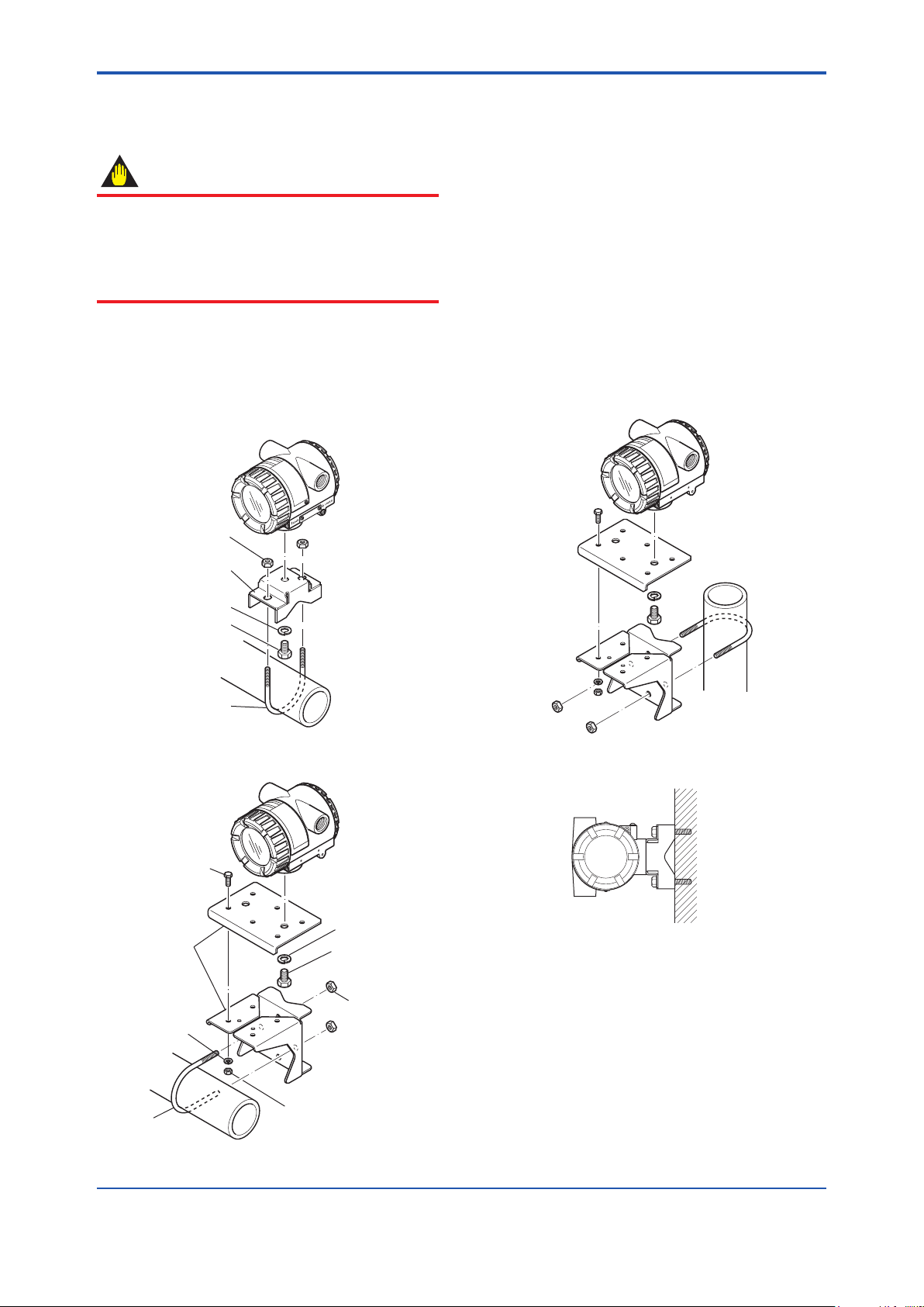
and also check that the transmitter mounting
parts shown in Figure 2.1 are included with your
shipment. If “No Mounting Bracket” is indicated, no
transmitter mounting bracket is included.
Bracket
fastening bolt
U-bolt nut
Vertical pipe
mounting
bracket
Spring
washer
Bracket
fastening nut
Figure 2.1 Transmitter mounting parts
Spring
washer
U-bolt
U-bolt nut
Horizontal
pipe mounting
bracket
Transmitter
fastening bolt
F0201.ai
2.1 Nameplate
2.3 Storage
When an extended storage period is expected,
observe the following precautions:
1. If at all possible, store the transmitter in
factoryshipped condition, that is, in the original
shipping container.
2. Choose a storage location that satises the
following requirements.
• A location that is not exposed to rain or water.
• A location subject to a minimum of vibration or
impact.
• The following temperature and humidity range
is recommended. Ordinary temperature and
humidity (25°C, 65%) are preferable.
Temperature:
No Integral indicator –40 to 85°C
With Integral indicator –30 to 80°C
Humidity: 5 to 100% RH (at 40°C)
3. The performance of the transmitter may
be impaired if stored in an area exposed to
direct rain and water. To avoid damage to
the transmitter, install it immediately after
removal from shipping container. Follow wiring
instructions in Chapter 5.
The model name and conguration are indicated
on the nameplate. Verify that the conguration
indicated in the “Model and Sufx Code” in Chapter
7 is in compliance with the specications written on
the order sheet.
Specification code
TEMPERATURE
TRANSMITTER
YTA
MODEL
SUFFIX
STYLE
SUPPLY
Style code
Figure 2.2 Name plate
Model name
NO.
OUTPUT
CAL
RNG
Serial No.
Factory-shipped range and unit
F0202.ai
2.2 Transport
To prevent damage while in transit, leave the
transmitter in the original shipping container until it
reaches the installation site.
2.4 Choosing the Installation
Location
Although the temperature transmitter is designed to
operate in a vigorous environment, to maintain
stability and accuracy, the following is
recommended:
(1) Ambient Temperature
It is preferable to not to expose the instrument to
extreme temperatures or temperature uctuations.
If the instrument is exposed to radiation heat
a thermal protection system and appropriate
ventilation is recommended.
(2) Environmental Requirements
Do not allow the instrument to be installed in a
location that is exposed to corrosive atmospheric
conditions. When using the instrument in a
corrosive environment, ensure the location is well
ventilated.
The unit and its wiring should be protected from
exposure to rainwater.
IM 01C50B01-01E
Page 8

<2. Notes on Handling>
2-2
IM 01C50B01-01E
CAUTION
(3) Impact and Vibration
It is recommended that the instrument be installed
in a location that is subject to a minimum amount of
impact and vibration.
2.5 Use of a Transceiver
Although the temperature transmitter is designed to
resist inuence from high frequency noise; use of a
transceiver in the vicinity of installation may cause
problems. Installing the transmitter in an area free
from high frequency noise (RFI) is recommended.
2.6 Insulation Resistance Test and Withstand Voltage Test
(1) Overvoltage of the test voltage that is so
small that it does not cause an dielectric
breakdown may in fact deteriorate insulation
and lower the safety performance; to prevent
this it is recommended that the amount of
testing be kept to a minimum.
(2) The voltage for the insulation resistance
test must be 500 VAC or lower, and the
voltage for the withstand voltage test must
be 500 VAC or lower. Failure to heed these
guidelines may cause faulty operation.
(3) Where a built-in arrester is provided (suffix
code: /A), the voltage for the insulation
resistance test must be 100 VDC or lower,
and the voltage for the withstand voltage test
must be 100 VAC or lower. Failure to heed
these guidelines may cause faulty operation.
Follow the steps below to perform the test, the
wiring of the transmission line must be removed
before initiating testing.
2.6.1 Insulation resistance test procedure
Testing between the output terminal and
nput terminal
i
1. Lay transition wiring between the + terminal,
the – terminal, and the check terminal of the
terminal box.
2. Lay wiring across terminals 1, 2, 3, and 4 of the
terminal box.
3. Connect the insulation resistance meter (with
the power turned OFF) between the transition
wiring of Steps 1 and 2 above. The polarity of
the input terminals must be positive and that of
the output terminals must be negative.
4. T
urn the power of the insulation resistance
meter ON and measure the insulation
resistance. The duration of the applied voltage
must be the period during which 100MΩ
or more is conrmed (or 20MΩ if the unit is
equipped with a built-in arrester).
5. Upon completion of the test, remove the
insulation resistance meter, connect a 100KΩ
resistor between the transition wiring, and
allow the electricity to discharge. Do not
touch the terminal with your bare hands while
the electricity is discharging for more than 1
second.
Testing between the output terminal and
grounding terminal
1. Lay transition wiring between the + terminal,
the - terminal, and the check terminal of the
terminal box, then connect an insulation
resistance meter (with the power turned OFF)
between the transition wiring and the grounding
terminal. The polarity of the transition wiring
must be positive and that of the grounding
terminal must be negative.
2. Turn the power of the insulation resistance
meter ON and measure the insulation
resistance. The duration of the applied voltage
must be the period during which 100MΩ
or more is conrmed (or 20MΩ if the unit is
equipped with a built-in arrester).
3. Upon completion of the test, remove the
insulation resistance meter, connect a 100KΩ
resistor between the transition wiring and the
grounding terminal, and allow the electricity to
discharge. Do not touch the terminal with your
bare hands while the electricity is discharging
for more than 1 second.
Testing between the input terminal and
grounding terminal
1. Lay transition wiring between terminals 1, 2,
3, 4 and 5 of the terminal box, and connect the
insulation resistor (with the power turned OFF)
between the transition wiring and the grounding
terminal. The polarity of the transition wiring
must be positive and that of the grounding
terminal must be negative.
2. Turn the power of the insulation resistance
meter ON and measure the insulation
resistance. The duration of the applied voltage
must be the period during which 100MΩ
Page 9

<2. Notes on Handling>
CAUTION
2-3
or more is conrmed (or 20MΩ if the unit is
equipped with a built-in arrester).
3. Upon completion of the test, remove the
insulation resistance meter, connect a 100KΩ
resistor between the transition wiring and the
grounding terminal, and allow the electricity to
discharge. Do not touch the terminal with your
bare hands while the electricity is discharging
for more than 1 second.
2.6.2 Withstand voltage test procedure
Testing between the output terminal and
he input terminal
t
1. Lay transition wiring between the + terminal,
the – terminal, and the check terminal of the
terminal box.
2. Lay transition wiring between terminals 1, 2, 3,
4 and 5 of the terminal box.
3. Connect the withstand voltage tester (with
the power turned OFF) between the transition
wiring shown in Steps 1 and 2 above.
4. After setting the current limit value of the
withstand voltage tester to 10mA, turn
the power ON, and carefully increase the
impressed voltage from 0V to the specied
value.
5. The voltage at the specied value must remain
for a duration of one minute.
6. Upon completion of the test, carefully reduce
the voltage so that no voltage surge occurs.
Testing between the output terminal and
the grounding terminal
1. Lay the transition wiring between the + terminal,
the - terminal and the check terminal of the
terminal box, and connect the withstand voltage
tester (with the power turned OFF) between the
transition wiring and the grounding terminal.
Connect the grounding side of the withstand
voltage tester to the grounding terminal.
2. After setting the current limit value of the
withstand voltage tester to 10mA, turn the
power ON, and gradually increase the
impressed voltage from 0V to the specied
value.
3. The voltage at the specied value must remain
for a duration of one minute.
4. Upon completion of the test, carefully reduce
the voltage so that no voltage surge occurs.
Testing between the input terminal and
the grounding terminal
1. Lay the transition wiring across terminals 1, 2,
3, 4, and 5 of the terminal box and connect the
withstand voltage tester (with the power turned
OFF) between the transition wiring and the
grounding terminal. Connect the grounding side
of the withstand voltage tester to the grounding
terminal.
fter setting the current limit value of the
2. A
withstand voltage tester to 10mA, turn the
power ON, and gradually increase the
impressed voltage from 0V to the specied
value.
3. The voltage at the specied value must remain
for a duration of one minute.
4. Upon completion of the test, carefully reduce
the voltage so that no voltage surge occurs.
2.7 Installation of Explosion
Protected Type Transmitters
In this section, further requirements and differences
and for explosionproof type instrument are
described. For explosionproof type instrument,
the description in this chapter is prior to other
description in this users manual.
To preserve the safety of explosionproof
equipment requires great care during mounting,
wiring, and piping. Safety requirements also
place restrictions on maintenance and repair
activities. Please read the following sections very
carefully.
2.7.1 CSACertication
Model YTA110/CU1, YTA310/CU1 and YTA320/
CU1 temperature transmitters can be selected the
type of protection (CSA Intrinsically Safe, Nonincendive, or Explosionproof) for use in hazardous
locations.
te 1. For the installation of this transmitter, once
No
a particular type of protection is selected, any
other type of protection cannot be used. The
installation must be in accordance with the
description about the type of protection in this
instruction manual.
Note 2. In order to avoid confusion, unnecessary
marking is crossed out on the label other
than the selected type of protection when the
transmitter is installed.
IM 01C50B01-01E
Page 10
<2. Notes on Handling>
2-4
IM 01C50B01-01E
F0203.ai
Safety Barrier
Supply
Hazardous Location Nonhazardous Location
General
Purpose
Equipment
+
–
+
–
+
–
Supply
+
–
+
–
[Intrinsically Safe]
Hazardous Location Nonhazardous Location
Not Use
Safety Barrier
+
–
[Non-incendive]
General
Purpose
Equipment
Sensor
1
2
3
4
5
Sensor
1
2
3
4
5
YTA Series
Temperature
Transmitter
YTA Series
Temperature
Transmitter
a) CSA Intrinsically Safe Type/Non-incendive
Type
Caution for CSA Intrinsically safe type. (Following
contents refers “DOC No. ICS008-A13 P.1-1 and
P.1- 2”)
Note 1. Model YTA110/CU1, YTA310/CU1 and
YTA320/CU1 temperature transmitters are
applicable for use in hazardous locations:
Certicate 172608-0001053837
[For CSA C22.2]
plicable Standard: C22.2 No.0,
• Ap
C22.2 No.0.4, C22.2 No.25, C22.2 No.94,
C22.2 No.142, C22.2 No.157, C22.2 No.213
• Intrinsically Safe for Class I, II, III, Division 1,
Groups A, B, C, D, E, F & G.
• Non-incendive for Class I, II, Division 2, Groups
A, B, C, D, F & G, Class III, Division 1.
• Encl. “Type 4X”
• Temperature Class: T4
• Ambient temperature: –40 to 60°C
Note 2. Entity Parameters (Electrical/Nonincendive
eld wiring parameters)
• [Supply Circuit]
Vmax = 30 V, Imax = 165 mA, Pmax = 0.9 W,
Ci = 18 nF, Li = 730 μH
• [Associated apparatus]
Voc ≤ 30 V, Isc ≤ 165 mA, Pmax ≤ 0.9 W
• [Sensor Circuit]
Voc = 9 V, Isc = 40 mA, Po = 90 mW,
Ca = 1 μF, La = 10 mH
Note 3. Installation
• All wiring shall comply with Canadian Electrical
Code Part I and Local Electrical Codes.
• For the sensor circuitry, the above parameters
for sensor circuit must be taken into account.
• Dust-tight conduit seal must be used when
installed in class II and III environments.
• In any used safety barrier, output current must
be limited by a resistor 'R' such that Isc=Voc/R.
• The safety barrier must be CSA certied, and
the input voltage of the barrier must be less
than 250Vrms/Vdc.
• For non-incendive type, general purpose
equipment must be CSA certied and the
equipment which have non-incendive eld
wiring parameters.
• The instrument modication or parts replacement
by other than authorized representative of
Yokogawa Electric Corporation is prohibited
and will void Canadian Standards Intrinsically
safe and nonincendive Certication.
b) CSA Explosionproof Type
Caution for CSA Explosionproof type
Note 1. Model YTA110/CU1, YTA310/CU1 and
YTA320/CU1 temperature transmitters are
applicable for use in hazardous locations:
Certicate 1089576
[For CSA C22.2]
plicable Standard: C22.2 No.0,
• Ap
C22.2 No.0.4, C22.2 No.25, C22.2 No.30,
C22.2 No.94, C22.2 No.142, C22.2 No.157,
C22.2 No.213, C22.2 No.1010.1
• Explosionproof for Class I, Division 1, Groups
B, C and D.
• Dust-ignitionproof for Class II, Groups E, F and
G, Class III.
• Encl “Type 4X”
• Temperature Class: T6
• Ambient Temperature: –40 to 60°C
• Supply Voltage: 42 V dc max.
• Output Signal: 4 to 20 mA
Note 2. Wiring
• All wiring shall comply with Canadian Electrical
Code Part I and Local Electrical Codes.
• In hazardous location, wiring shall be in conduit
as shown in the gure.
WARNING: A SEAL SHALL BE INSTALLED
WITHIN 50 cm OF THE
ENCLOSURE. UN SCELLEMENT
DOIT ÊTRE INSTALLÉ À MOINS
DE 50 cm DU BOÎTIER.
Page 11
<2. Notes on Handling>
Sensor
Sensor
Non-hazardous
Location
Equipment
42 V DC Max.
4 to 20 mA DC
Signal
Non-hazardous LocationsHazardous Locations Division 1
50 cm Max.
Sealing Fitting
Conduit
Non-hazardous
Location
Equipment
42 V DC Max.
4 to 20 mA DC
Signal
Non-hazardous LocationsHazardous Locations Division 2
Sealing Fitting
Sealing Fitting
50 cm Max.
Certified/Listed Temperature Sensor
Explosionproof Class I, Groups C and D
Dustignitionproof Class II, Groups E, F and G, Class III
Wiring method shall be suitable for the specified hazardous locations.
YTA Series
YTA Series
Conduit
F0204.ai
Certified/Listed Temperature Sensor
Explosionproof Class I, Groups C and D
Dustignitionproof Class II, Groups E, F and G, Class III
Wiring method shall be suitable for the specified hazardous locations.
2-5
• When installed in Division 2, “FACTORY
SEALED, CONDUIT SEAL NOT REQUIRED”.
Note 3. Operation
• Keep strictly the “WARNING” on the label
attached on the transmitter.
WARNING: OPEN CIRCUIT BEFORE
REMOVING COVER. OUVRIR LE
CIRCUIT AVANT D´ENLEVER LE
COUVERCLE.
• Take care not to generate mechanical spark
when access to the instrument and peripheral
devices in hazardous location.
Note 4. Maintenance and Repair
• The instrument modication or parts
replacement by other than authorized
representative of Yokogawa Electric
Corporation is prohibited and will void Canadian
Standards Explosionproof Certication.
2.7.2 ATEXCertication
Model YTA110/KU2, YTA310/KU2 and YTA320/
KU2 temperature transmitters can be selected the
type of protection (ATEX Intrinsically Safe “ia” or
ATEX Flameproof or ATEX Intrinsically Safe “ic”) for
use in hazardous locations.
Note 1. For the installation of this transmitter, once
a particular type of protection is selected, any
other type of protection cannot be used. The
installation must be in accordance with the
description about the type of protection in this
instruction manual.
Note 2. In order to avoid confusion, unnecessary
marking is crossed out on the label other
than the selected type of protection when the
transmitter is installed.
IM 01C50B01-01E
Page 12
<2. Notes on Handling>
2-6
IM 01C50B01-01E
Transmitter
Supply
Safety Barrier
*1
Hazardous Location Nonhazardous Location
+
–
+
–
[Installation Diagram]
F0205.ai
Sensor
1
2
3
4
5
(1) Technical Data
a) ATEX Intrinsically Safe “ia”
Caution for ATEX Intrinsically safe “ia”
Note 1. Model YTA110/KU2, YTA310/KU2 and
YTA320/KU2 temperature transmitters for
potentially explosive atmospheres:
. KEMA 02ATEX1026X
• No
• Applicable Standard: EN 60079-0:2009,
EN 60079-11:2007, EN 60079-26:2007,
EN 60529:1991
• Type of Protection and Marking code: II 1 G Ex
ia IIC T4...T5
• Temperature Class: T5, T4
• Ambient Temperature: –40 to 70°C for T4,
–40 to 50°C for T5
• Enclosure: IP67
Note 2. Electrical Data
• In type of explosion protection intrinsic safety II
1 G Ex ia IIC only for connection to a certied
intrinsically safe circuit with following maximum
values:
• [S
upply circuit]
Ui = 30 V Ii = 165 mA
Pi = 900 mW
Effective internal capacitance, Ci = 20 nF
Effective internal inductance, Li = 730 μH
• [Sensor circuit]
Uo = 9 V Io = 40 mA
Po = 90 mW
Max. allowed external capacitance, Co = 0.7μF
Max. allowed external inductance, Lo = 10 mH
• The above parameters apply when one of the
two conditions below is given:
- the total Li of the external circuit (excluding
the cable) is < 1% of the Lo value or
- the total Ci of the external circuit (excluding
the cable) is < 1% of the Co value.
• The above parameters are reduced to 50%
when both of the two conditions below are
given:
e total Li of the external circuit (excluding
- th
the cable) is ≥ 1% of the Lo value and
- the total Ci of the external circuit (excluding
the cable) is ≥ 1% of the Co value.
• The reduced capacitance of the external circuit
(including cable) shall not be greater than 1μF
for Group IIB and 600nF for Group IIC.
Note 3. Installation
• All wiring shall comply with local installation
requirements. (Refer to the installation diagram)
Note 4. Operation
• Keep strictly the “WARNING” on the label on
the transmitter.
WA
RNING: POTENTIAL ELECTROSTATIC
CHARGING HAZARD. SEE
USER’S MANUAL BEFORE USE.
Note 5. Maintenance and Repair
• The instrument modication or parts
replacement by other than authorized
representative of Yokogawa Electric
Corporation is prohibited and will void ATEX
Intrinsically safe “ia” Certication.
Note 6. Specic condition of use
• Because the enclosure of the Temperature
Transmitter is made of aluminium, if it is
mounted in an area where the use of category
1G apparatus is required, it must be installed
such, that, even in the event of rare incidents,
ignition source due to impact and friction sparks
are excluded.
• Avoid any actions that cause the generation of
electrostatic charge on the non-metallic parts,
such as rubbing with a dry cloth on coating face
of product.
*1: In any safety barriers used the output current must be
limited by a resistor “R” such that Imaxout-Uz/R.
b) ATEX Flameproof Type and Dust Ignition
Proof Type
Caution for ATEX Flameproof Type and Dust
Ignition Proof Type
Note 1. Model YTA110/KU2, YTA310/KU2 and
YTA320/KU2 temperature transmitters are
applicable for use in hazardous locations:
. KEMA 07ATEX0130
• No
• Applicable Standard: EN 60079-0:2006,
IEC 60079-1:2007, EN 61241-0:2006,
EN 61241-1:2004
• Type of Protection and Marking Code: II 2 G
Ex d IIC T6/T5, II 2 D Ex tD A21 IP67 T70°C,
T90°C
• Ambient Temperature for Gas Atmospheres:
–40 to 75°C (T6), –40 to 80°C (T5)
Page 13

<2. Notes on Handling>
WARNING
2-7
• Ambient Temperature for Dust Atmospheres:
–40 to 65°C (T70°C), –40 to 80°C (T90°C)
• Enclosure: IP67
Note 2. Electrical Data
• Supply voltage: 42 V dc max.
• Output signal: 4 to 20 mA
Note 3. Installation
• All wiring shall comply with local installation
requirement.
• The cable entry devices shall be of a certied
ameproof type, suitable for the conditions of
use.
Note 4. Operation
• Keep strictly the “WARNING” on the label on
the transmitter.
WARNING: AFTER DE-ENERGIZING, DELAY
5 MINUTES BEFORE OPENING.
WHEN THE AMBIENT TEMP. ≥
70°C, USE THE HEATRESISTING
CABLES OF HIGHER THAN
90°C.
• Take care not to generate mechanical spark
when access to the instrument and peripheral
devices in hazardous location.
Note 5. Maintenance and Repair
• The instrument modication or parts
replacement by other than authorized
representative of Yokogawa Electric
Corporation is prohibited and will void ATEX
Flameproof Certication.
c) ATEX Intrinsically Safe “ic”
When using a power supply not having a nonincendive circuit, please pay attention not to
ignite in the surrounding ammable atmosphere.
In such a case, we recommend using wiring
metal conduit in order to prevent the ignition.
Caution for ATEX Intrinsically Safe “ic”
Note 1. Model YTA110/KU2, YTA310/KU2 and
YTA320/KU2 temperature transmitters for
potentially explosive atmospheres:
plicable standard: EN 60079-0:2009,
• Ap
EN 60079-0:2012, EN 60079-11:2012
• Type of Protection and Marking:
II 3 G Ex ic IIC T5…T4 Gc
• Ambient Temperature: –30 to 50°C for T5,
–30 to 70°C for T4
• IP Code: IP67
• Overvoltage Category: I
Note 2. Electrical Data
upply circuit]
• [S
Ui = 30 V
Effective internal capacitance, Ci = 28 nF
Effective internal inductance, Li = 730 μH
• [Sensor circuit]
Uo= 9 V Io = 40 mA Po = 90 mW
Max. allowed external capacitance, Co = 0.7 μF
Max. allowed external inductance, Lo = 10 mH
• The above parameters apply when one of the
two conditions below is given:
- the total Li of the external circuit (excluding
the cable) is < 1% of the Lo value or
- the total Ci of the external circuit (excluding
the cable) is < 1% of the Co value.
• The above parameters are reduced to 50%
when both of the two conditions below are
given:
- the total Li of the external circuit (excluding
the cable) is ≥ 1% of the Lo value and
- the total Ci of the external circuit (excluding
the cable) is ≥ 1% of the Co value.
• The reduced capacitance of the external circuit
(including cable) shall not be greater than 1μF
for Group IIB and 600nF for Group IIC.
Note 3. Installation
• All wiring shall comply with local installation
requirements. (refer to the installation diagram)
• Cable glands, adapters and/or blanking
elements shall be of Ex “n”, Ex “e” or Ex “d” and
shall be installed so as to maintain the specied
degree of protection (IP code) of the equipment.
Note 4. Operation
• Keep strictly the “WARNING” on the label on
the transmitter.
WARNING: POTENTIAL ELECTROSTATIC
CHARGING HAZARD - SEE USER’S MANUAL
Note 5. Maintenance and Repair
• The instrument modication or parts
replacement by other than authorized
representative of Yokogawa Electric
Corporation is prohibited and will void ATEX
Intrinsically Safe “ic“.
Note 6. Specic Conditions of Use
• Precautions shall be taken to minimize the risk
from electrostatic discharge of painted parts.
• The dielectric strength of at least 500 V a.c.
r.m.s between the intrinsically safe circuits
and the enclosure of the Model YTA series
temperature transmitter is limited only by the
overvoltage protection.
IM 01C50B01-01E
Page 14
<2. Notes on Handling>
2-8
IM 01C50B01-01E
Temperature Transmitter
Electrical data are as follows;
Supply Input (Terminals: + and -)
Ui = 30 V
Ci = 28 nF
Li = 730 μH
Sensor Output (Terminals: 1 to 5)
Uo = 9 V
Io = 40 mA
Po = 90 mW
Co = 0.7 μF
Lo = 10 mH
SUPPLY
SUPPLY
SENSOR
Associated Apparatus
Hazardous Area Non-hazardous Area
+
–
+
–
C
F0206.ai
1
2
3
4
5
SENSOR
MarkingScrew Size
ISO M20×1.5 female M
AANSI 1/2 NPT female
T0201.ai
F0207.ai
Location of the marking
WARNING
WARNING
WARNING
F0208.ai
TEMPERATURE
TRANSMITTER
YTA
MODEL
SUFFIX
STYLE
SUPPLY
NO.
OUTPUT
CAL
RNG
*3
(5) Maintenance and Repair
The instrument modication or parts replacement
by other than authorized Representative of
Yokogawa Electric Corporation is prohibited and
will void the certication.
(6) Name Plate
(2) Electrical Connection
The type of electrical connection is stamped near
the electrical connection port according to the
following marking.
(3) Installation
All wiring shall comply with local installation
requirement and local electrical code.
(4) Operation
• OPEN CIRCUIT BEFORE REMOVING
COVER. INSTALL IN ACCORDANCE WITH
THIS USER’S MANUAL
• Take care not to generate mechanical
sparking when access to the instrument and
peripheral devices in hazardous locations.
MODEL: Specied model code.
SUFFIX: Specied sufx code.
STYLE: Style code.
SUPPLY: Supply voltage.
NO.: Serial number and year of production*1.
OUTPUT: Output signal.
FACTORY CAL: Specied calibration range.
TOKYO 180-8750 JAPAN:
The manufacturer name and the address*2.
*1: The third gure from the left shows the production year.
The relationship between the production year and the
third gure is shown below.
The third gure F G H J K L M
The year of
Production
2006 2007 2008 2009 2010 2011 2012
Page 15
<2. Notes on Handling>
The year 2006
C2F616294
F0209.ai
Class I, II, III, Division 1,
Groups A, B, C, D, E, F and G
Temperature
Transmitter
Safety Barrier
Hazardous
Location
Nonhazardous
Location
General
Purpose
Equipment
+
–
+ –
+
–
C
+
–
[Intrinsically Safe]
Supply
1
2
3
4
5
Sensor
Intrinsically
Safe Sensor
or Simple
Apparatus
2-9
For example, the production year of the product engraved
in “NO.” column on the name plate as follows is 2006.
*2: “180-8750” is a postal code which represents the following
address.
2-9-32 Nakacho, Musashino-shi, Tokyo Japan
*3: The identication number of Notied Body
2.7.3 FMCertication
a) FM Intrinsically Safe Type
Caution for FM Intrinsically safe type.
Note 1. Model YTA /FU1 temperature transmitter is
applicable for use in hazardous locations.
plicable Standard: FM 3600, FM 3610,
• Ap
FM 3611, FM 3810, NEMA-250
• Intrinsically Safe for Class I, Division 1, Groups
A, B, C & D.
Class II, Division 1, Groups E, F & G and Class
III, Division 1 Hazardous Locations.
• Outdoor hazardous locations, NEMA 4X.
• Temperature Class: T4
• Ambient temperature: –40 to 60°C
Note 2. Entity Parameters of the temperature
transmitter:
• Supply Circuit (+ and –) • Sensor Circuit (1 to 5)
Vmax : 30 V Voc/Vt : 9 V
Imax : 165 mA Isc/It : 40 mA
Pmax : 0.9 W Po : 0.09 W
Ci : 18 nF Ca : 1 μF
Li : 730 μH La : 10 mH
• For the sensor input circuitry, these entity
parameters must be taken into account when
installed.
• Installation Requirements between temperature
transmitter and safety barrier:
Voc ≤ Vmax, Isc ≤ Imax, Ca ≥ Ci + Ccable, La ≥
Li + Lcable
Voc, Isc, Ca and La are parameters of the
safety barrier.
Note 3. Installation
• The safety barrier must be FM approved.
• Input voltage of the safety barrier must be less
than 250 Vrms/Vdc.
• Installation should be in accordance with ANSI/
ISA RP12.6 “Installation of Intrinsically Safe
Systems for Hazardous (Classied) Locations”
and the National Electric Code (ANSI/NFPA
70).
• Intrinsically safe sensor must be FMRC
Approved or be simple apparatus (a device
which will neither generate nor store more than
1.2 V, 0.1 A, 25 mW or 20 μJ, ex. switches,
thermocouples, LED’s or RTD’s).
st-tight conduit seal must be used when
• Du
installed in a Class II and III environments.
Note 4. Maintenance and Repair
• The instrument modication or parts
replacement by other than authorized
representative of Yokogawa Electric
Corporation is prohibited and will void Factory
Mutual Intrinsically safe and Nonincendive
Approval.
b) FM Non-incendive Type
Caution for FM Non-incendive type.
Note 1. Model YTA /FU1 temperature transmitter is
applicable for use in hazardous locations.
plicable Standard: FM 3600, FM 3610,
• Ap
FM 3611, FM 3810, NEMA-250
• Non-incendive for Class I, Division 2, Groups A,
B, C & D.
Class II, Division 2, Groups F & G and Class III,
Division 1 Hazardous Locations.
• Outdoor hazardous locations, NEMA 4X.
• Temperature Class: T4
• Ambient temperature: –40 to 60°C
Note 2. Non-incendive eld wiring Parameters of
the temperature transmitter:
• Supply Circuit (+ and -) • Sensor Circuit (1 to 5)
Vmax : 30 V Voc/Vt : 9 V
Imax : 165 mA Isc/It : 40 mA
Pmax : 0.9 W Po : 0.09 W
Ci : 18 nF Ca : 1 μF
Li : 730 μH La : 10 mH
IM 01C50B01-01E
Page 16

<2. Notes on Handling>
2-10
IM 01C50B01-01E
F0210.ai
Temperature
Transmitter
General
Purpose
Equipment
+
–
C
Supply
1
2
3
4
5
Sensor
Non-incendive
Sensor
or Simple
Apparatus
Class I, II, Division 2,
Groups A, B, C, D, E, F and G
Class III, Division 1.
Hazardous
Location
Nonhazardous
Location
+
–
[Nonincendive]
• For the sensor input circuitry, these nonincendive parameters must be taken into
account when installed.
• Installation Requirements between temperature
transmitter and general purpose equipment:
Voc ≤ Vmax, Isc ≤ Imax, Ca ≥ Ci + Ccable, La ≥
Li + Lcable
Voc , Isc, Ca and La are non-incendive
eld wiring parameters of general purpose
equipment.
Note 3. Installation
• The general purpose equipment must be FM
approved which have non-incendive eld wiring
parameters.
• Installation should be in accordance with ANSI/
ISA RP12.6 “Installation of Intrinsically Safe
Systems for Hazardous (Classied) Locations”
and the National Electric Code (ANSI/NFPA
70).
• Non-incendive sensor must be FMRC
Approved or be simple apparatus (a device
which will neither generate nor store more than
1.2 V, 0.1 A, 25 mW or 20 μJ, ex. switches,
thermocouples, LED’s or RTD’s).
• Dust-tight conduit seal must be used when
installed in a Class II and III environments.
Note 4. Maintenance and Repair
• The instrument modication or parts
replacement by other than authorized
representative of Yokogawa Electric
Corporation is prohibited and will void Factory
Mutual Intrinsically safe and Nonincendive
Approval.
c) FM Explosionproof Type
Caution for FM Explosionproof type
Note 1. Model YTA /FU1 and YTA /FF1 temperature
transmitters are applicable for use in hazardous
locations:
• Applicable Standard: FM 3600, FM 3615,
FM 3810, NEMA-250
• Explosionproof for Class I, Division 1, Groups
A, B, C, and D.
• Dust-ignitionproof for Class II/III, Division 1,
Groups E, F and G.
• Enclosure rating: NEMA 4X.
• Temperature Class: T6
• Ambient Temperature: –40 to 60°C
• Supply Voltage: 42 V dc max.
• Output signal: 4 to 20 mA
Note 2. Wiring
• All wiring shall comply with National Electrical
Code ANSI/NEPA70 and Local Electrical
Codes.
• “FACTORY SEALED, CONDUIT SEAL NOT
REQUIRED”.
Note 3. Operation
• Keep strictly the “WARNING” on the nameplate
attached on the transmitter.
RNING: OPEN CIRCUIT BEFORE
WA
REMOVING COVER. “FACTORY
SEALED, CONDUIT SEAL
NOT REQUIRED”. INSTALL
IN ACCORDANCE WITH THE
INSTRUCTION MANUAL IM
1C50B1.
• Take care not to generate mechanical spark
when access to the instrument and peripheral
devices in hazardous location.
Note 4. Maintenance and Repair
• The instrument modication or parts
replacement by other than authorized
representative of Yokogawa Electric
Corporation is prohibited and will void Factory
Mutual Explosionproof Approval.
Page 17

<2. Notes on Handling>
WARNING
2-11
2.7.4 TIISCertication
a) TIIS Flameproof Type
The model YTA /JF3 temperature transmitter, which
has obtained certication according to technical
criteria for explosion-protected construction of
electric machinery and equipment (Standards
Notication No.556 from the Japanese Ministry of
Labor) conforming to IEC standards, is designed
for hazardous areas where explosive gases and/or
inammable vapors may be present. (This allows
installation in Division 1 and 2 areas) To preserve
the safety of ameproof equipment requires
great care during mounting, wiring, and piping.
Safety requirements also place restrictions on
maintenance and repair activities. Users absolutely
must read “Installation and Operating Precautions
for TIIS Flameproof Equipment” at the end of this
manual.
The terminal cover should not be opened at least
for three minutes after the power is turned off.
The terminal section of the ameproof YTA
series is made of resin-lled, explosionprotected construction. The technical standards
for this ameproof construction require that
the possibility of explosion resulting from a
prospective short-circuit current*1 of up to 4000
A be prevented even for cases when external
power supply circuits are short-circuited
accidentally.
Install a fuse or a circuit breaker having a
breaking capacity of at least 4000 A in the higherorder power line connected to the YTA series.
The breaking capacity refers to the upper limit
of current that can be cut off. Normally, a fuse
or a circuit breaker having a breaking capacity
of greater than 5000 A is used in power supply
circuits. Conrm that this is true with your factory.
No extra measures need be taken after the
conrmation.
Note that the rated current of the YTA series in
terms of explosion protection is 4 to 20 mA; keep
the input current of the YTA series within the
appropriate range.
*1: Refers to a current that ows when a fuse in a circuit is
substituted with a connecting metal piece having virtually
no impedance and the circuit is then shorted. For AC
circuits, this current is represented by a root-mean-square
value (JIS C6575).
2.7.5 IECExCertication
a) IECEx Intrinsic safety “ia”
Caution for IECEx Intrinsic safety “ia”.
Note 1. Model YTA110/SU2, YTA310/SU2, and
YTA320/SU2 temperature transmitters are
applicable for use in hazardous locations:
. Certicate: IECEx KEM 09.0032X
• No
• Applicable standard: IEC60079-11:2011,
IEC60079-0:2011, IEC60079-26:2006
• Type of Protection and Marking Code:
Ex ia IIC T4...T5 Ga
• Ambient Temperature:
-40 to 70°C for T4, -40 to 50°C for T5
• Enclosure: IP67
Note 2. Electrical Data
• [Supply circuit (Terminals: + and –)]
Ui = 30 V, Ii = 165 mA, Pi = 900 mW
Effective internal capacitance, Ci = 20 nF
Effective internal inductance, Li = 730 μH
• [Sensor circuit (Terminals: 1 to 5)]
Uo = 9 V Io = 40 mA Po = 90 mW
Max. allowed external capacitance, Co = 0.7 μF
Max. allowed external inductance, Lo = 10 mH
Note 3. Installation
• All wiring shall comply with local installation
requirements. (Refer to the installation diagram)
Note 4. Operation
• Keep strictly the “WARNING” on the label on
the transmitter.
WARNING: POTENTIAL ELECTROSTATIC
CHARGING HAZARD. SEE
USER’S MANUAL BEFORE USE.
Note 5. Maintenance and Repair
• The instrument modication or parts
replacement by other than authorized
representative of Yokogawa Electric
Corporation is prohibited and will void IECEx
Certication.
Note 6. Conditions of Certication
• Because the enclosure of the Temperature
Transmitter is made of aluminium, if it is mounted
in zone 0, it must be installed such, that, even in
the event of rare incidents, ignition sources due
to impact and friction sparks are excluded.
• Avoid any actions that cause the generation of
electrostatic charge on the non-metallic parts,
such as rubbing with a dry cloth on coating face
of product.
IM 01C50B01-01E
Page 18

<2. Notes on Handling>
2-12
IM 01C50B01-01E
Transmitter
Supply
Safety Barrier
*1
Hazardous Location Nonhazardous Location
+
–
+
–
[Installation Diagram]
F0212.ai
Sensor
1
2
3
4
5
Temperature
Transmitter
Suppry
Power Supply
Hazardous Location
(Zone 2 only)
Nonhazardous Location
+
–
+
–
[Installation Diagram]
F0213.ai
*1: In any safety barriers used the output current must be
limited by a resistor “R” such that Imaxout-Uz/R.
b) IECEx Intrinsic safety “ic”
Caution for IECEx Intrinsic safety “ic”.
Note 1. Model YTA110/SU2, YTA310/SU2, and
YTA320/SU2 temperature transmitters are
applicable for use in hazardous locations:
. Certicate: IECEx KEM 09.0032X
• No
• Applicable standard: IEC60079-11:2011,
IEC60079-0:2011, IEC60079-26:2006
• Type of Protection and Marking Code:
Ex ic IIC T4...T5 Gc
• Ambient Temperature:
-40 to 70°C for T4, -40 to 50°C for T5
• Enclosure: IP67
Note 2. Electrical Data
• [Supply circuit (Terminals: + and –)]
Ui = 30 V, Ci = 20 nF, Li = 730 μH
• [Sensor circuit (Terminals: 1 to 5)]
Uo = 9 V, Io = 40 mA, Po = 90 mW, Co = 0.7 μF,
Lo = 10 mH
Note 3. Installation
• All wiring shall comply with local installation
requirements. (Refer to the installation diagram)
Note 4. Operation
• Keep strictly the “WARNING” on the label on
the transmitter.
WARNING: POTENTIAL ELECTROSTATIC
CHARGING HAZARD. SEE
USER’S MANUAL BEFORE USE.
Note 5. Maintenance and Repair
• The instrument modication or parts
replacement by other than authorized
representative of Yokogawa Electric
Corporation is prohibited and will void IECEx
Certication.
Note 6. Special condition for safe use
• Avoid any actions that cause the generation of
electrostatic charge on the non-metallic parts,
such as rubbing with a dry cloth on coating face
of product.
Ratings of the Power Supply are as follows:
Maximum Voltage: 30 V
c) IECEx Flameproof Type and Dust Ignition
Proof Type
Caution for IECEx ameproof type and Dust Ignition
Proof Type
Note 1. Model YTA110/SF2, YTA310/SF2, and
YTA320/SF2, YTA110/SU2, YTA310/SU2, and
YTA320/SU2 temperature transmitters are
applicable for use in hazardous locations:
. IECEx KEM 07.0044
• No
• Applicable Standard: IEC 60079-0,
IEC 60079-1, IEC 61241-0, IEC 61241-1
• Type of Protection and Marking Code:
Ex d IIC T6/T5, Ex tD A21 IP67 T70°C, T90°C
• Ambient Temperature for Gas Atmospheres:
–40 to 75°C (T6), –40 to 80°C (T5)
• Ambient Temperature for Dust Atmospheres:
–40 to 65°C (T70°C), –40 to 80°C (T90°C)
• Enclosure: IP67
Note 2. Electrical Data
• Supply voltage: 42 V dc max.
• Output signal: 4 to 20 mA
Note 3. Installation
• All wiring shall comply with local installation
requirement.
• The cable entry devices shall be of a certied
ameproof type, suitable for the conditions of
use.
Note 4. Operation
• Keep strictly the “WARNING” on the label on
the transmitter.
WARNING: AFTER DE-ENERGIZING, DELAY
5 MINUTES BEFORE OPENING.
WHEN THE AMBIENT TEMP. ≥
70°C, USE THE HEATRESISTING
CABLES OF HIGHER THAN
90°C.
• Take care not to generate mechanical spark
when access to the instrument and peripheral
devices in hazardous location.
Page 19

<2. Notes on Handling>
NOTE
Note 5. Maintenance and Repair
• The instrument modication or parts
replacement by other than authorized
representative of Yokogawa Electric
Corporation is prohibited and will void IECEx
Flameproof Certication.
2.8 EMC Conformity Standards
EN61326-1 Class A, Table 2 (For use in industrial
locations)
EN61326-2-3
YOKOGAWA recommends customer to apply
the Metal Conduit Wiring or to use the twisted
pair Shield Cable for signal wiring to conform the
requirement of EMC Regulation, when customer
installs the YTA Series Transmitters to the plant.
2-13
2.9 Low Voltage Directive
Applicable standard: EN61010-1
(1) Pollution Degree 2
“Pollution degree” describes the degree to
which a soild, liquid, or gas which deteriorates
dielectric strength or surface resistivity is
adhering. “ 2 ” applies to normal indoor
atmosphere. Normally, only non-conductive
pollution occurs. Occasionally, however,
temporary conductivity caused by condensation
must be expected.
(2) Installation Category I
“Overvoltage category(Installation category)”
describes a number which denes a transient
overvoltage condition. It implies the regulation
for impulse withstand voltage. “ I ” applies to
electrical equipment which is supplied from the
circuit when appropriate transient overvoltage
control means (interfaces) are provided.
IM 01C50B01-01E
Page 20

<3. Part Names and Functions>
F0301.ai
Amp. cover
LCD assembly
(with indicator)
Burn out output direction
setting pin upon hardware failure
CPU assembly
Stud bolt
Name plate
Grounding
terminal
Terminal cover
Grounding
terminal
Wiring connector
(input signal side)
Output signal terminal
Wiring connector
(output signal side)
Input signal terminal
Tag plate
Lock screw
(for ATEX, IECEx and
TIIS flameproof type)
Built-in indicator display
3. Part Names and Functions
3.1 Part Names
3-1
Figure 3.1 Part Names
IM 01C50B01-01E
Page 21

<3. Part Names and Functions>
3-2
IM 01C50B01-01E
T0301.ai
H
L
H
L
Pin
position
RemarkHardware error
burnout
direction
HIGH
LOW
110% or more
(21.6 mA DC)
-5% or less
(3.2 mA DC)
Set to HIGH upon
shipment from the
factory
Set to LOW when
suffix code /C1
is provided
Hardware error
burnout
output
F0302.ai
Output bar chart display
Communication protocol display
Operation mode
display
Display of sensor type and
number of wire connections
Unit display
Process variable display
Input display
3.2 Setting the Hardware Error Burnout Change-over Switch
The temperature transmitter is equipped with a
hardware error burnout function used to set the
output direction upon hardware error, and a sensor
burnout function that sets the direction of the output
in the event of burnout of the temperature sensor.
When factory-shipped under normal conditions,
the output of both hardware error burnout and
sensor burnout are set to HIGH, but if sufx code
/C1 is specied, the hardware error burnout is set
to LOW (-5%) output, and sensor burnout is set to
LOW (-2.5%) output, respectively. The setting of the
direction of output from burnout can be changed.
To change the direction of output arising from
burnout, switch the setting pin on the CPU
assembly (see Figure 3.1 and Table 3.1). To change
the direction of output arising out of sensor burnout,
a dedicated hand-held terminal is required to
rewrite the parameters within the transmitter. For
details, refer to the separate instruction manual, IM
01C50T01-01E “HART Protocol” or IM 01C50T0301E “BRAIN Protocol”.
Table 3.1 Output Direction Setting Pins for
Hardware Error Burnout
(1) Output bar chart display
The output value is displayed in a bar chart.
Resolution of the bar chart is to the extent of 32
divisions (each increment is about 3.125%). If the
output exceeds 0% or 100%, ▼is lit. The bar chart
can be toggled ON/OFF using the bar chart display
parameter.
) Communication protocol display
(2
The indicator is on in accordance with each
communication protocol.
) Operation mode display
(3
Lit when each operation mode is activated.
D.: Lit when the multidrop mode of HART
M.
communication specication is activated.
B.M.: Lit during burst mode transfer of HART
communication specication.
F.O.: Lit when manual mode is active.
W.P.: Lit when write protect status is active.
(4) Input display
Indicates the type of input in accordance with the
value shown in the column in Item (5).
s1: Meant to show the process variable allocated
Sn
to Sensor 1.
3.3 Built-in Indicator Display Function
Figure 3.2 Built-in Indicator Display Function
s2: Meant to show the process variable allocated
Sn
to Sensor 2. (Can be displayed only with the
YTA320.) .
rm: Meant to show the temperature of the
Te
terminal box of the temperature transmitter.
g: Meant to show the average of the process
Av
variable allocated to Sensor1 and Sensor2.
(Can be displayed only with the YTA320.).
f: Meant to show the difference of the process
Di
variable allocated to Sensor1 and Sensor2.
(Can be displayed only with the YTA320.)
) Process variable display
(5
Displays the process variable or output value. The
value is displayed down to the second decimal
position if the integer part is less than three digits,
or down to the rst decimal position if the integer
part is 4 digits. If the value is negative, the minus (−)
sign is lit. For process variables, the indicators for
each item specied in the column of input display in
Item (4) and the unit column in Item (6) are lit. For
output value, % or mA in the unit column in Item (6)
is lit. When burnout of the temperature sensor is
identied, or the temperature transmitter is found
abnormal, an error code ashes.
Page 22

<3. Part Names and Functions>
3-3
For a list of error codes, refer to “Error code table” in
Section 6.4.
(6) Unit display
The unit specied as the unit of process in the
process variable display column in Item (5) is lit.
The output display is xed to mA or %.
) Display of sensor type and number of wire
(7
connections
Displays process variable/output items, the number
of sensor wiring connections and the multidrop
address in dot matrix (only applies to HART
communication). In the event of hardware error,
“FAIL” is displayed.
Process variable: To display the process variable
value in the process variable display in Item
(5), display the type of applicable process
variable (“PV”, “SV”, “TV”).
Output display: To display the output value in the
process variable display in Item (5), display
“OUT”. During the output of sensor burnout,
“Abn” and “OUT” are alternately dis played.
Table 3.2 Setting of Indicator upon Shipment
Display location Contents
Output bar chart display Output bar chart display
Input display Sns1 is lit.
Process variable display PV value and output
Unit display The unit specied upon
Display of sensor type
and number of wire
connections
from the Factory
is on.
value (mA) are alternately
displayed.
shipped from factory and
mA are lit.
“PV” and “OUT” are
displayed alternately.
WIRE: Displays the number of wiring connections.
There are two wiring connections for
thermocouple input, while there are two to
four connections for thermometer resistor;
these are displayed alternately with the
sensor type.
The display can be hidden by setting an
applicable parameter. Note that the DIF and
AVG display does not allow the sensor type
to be displayed.
TYPE: Displays the type of sensor. Note that the
DIF and AVG display does not allow the
sensor type to be displayed. If the sensor is
customordered, “Z1” and “Z2” are displayed.
Multidrop address: If the multidrop address is 1
through 15 in HART communication, the
output display brings up these addresses
instead of display ing “OUT”.
Upon shipment from the factory, the indicator is set
as follows.
IM 01C50B01-01E
Page 23
<4. Installation>
IMPORTANT
F0401.ai
Horizontal Pipe Mounting Vertical Pipe Mounting
U-bolt nut
Spring washer
Horizontal pipe
mounting bracket
U-bolt
Wall Mounting
Note: Wall mounting bolts are
user-supplied.
Transmitter
fastening bolt
U-bolt nut
Vertical pipe
mounting
bracket
Transmitter
fastening bolt
Spring washer
Spring washer
U-bolt
Bracket
fastening bolt
Bracket
fastening nut
• When using a horizontal pipe mounting bracket
• When using a vertical pipe mounting bracket
4. Installation
• For details of choosing the installation location,
refer to the guidelines outlined in Section 2.4,
• When performing on-site pipe tting work that
involves welding, use care to prevent outow
of the welding current into the transmitter.
• Do not use the transmitter as a foothold for
installation.
“Choosing the installation location”.
• Th
e mounting bracket shown in Figure 4.1 is
used for the transmitter and is installed on 50A
(2B) pipe.
It can be installed either on a horizontal pipe
and a vertical pipe or on a wall.
• To install the mounting bracket on the
transmitter, torque the transmitter lock screw (1)
to about 20 to 30N•m.
4-1
Figure 4.1 Mounting the Transmitter
IM 01C50B01-01E
Page 24
<5. Wiring>
IMPORTANT
F0501.ai
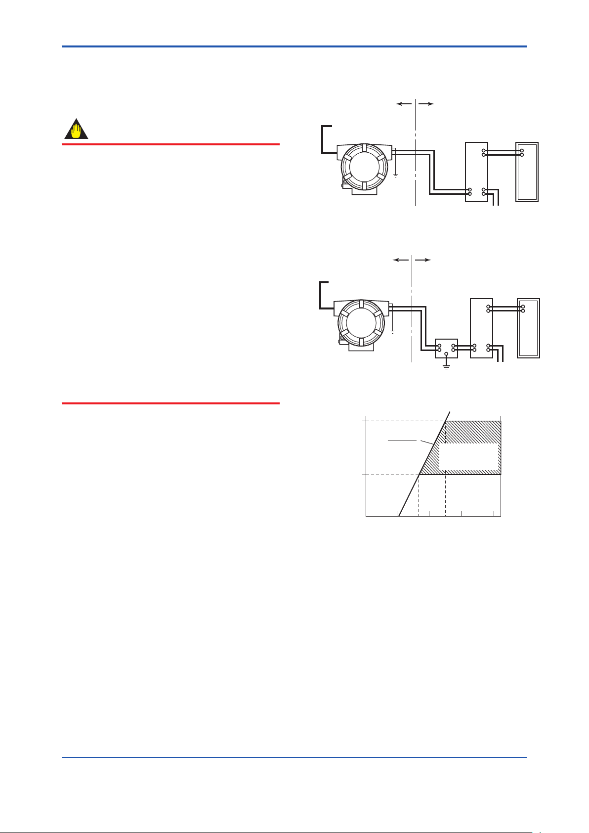
<Hazardous location> <Nonhazardous location>
+
Output signal
–
Distributor
(power supply unit)
Receiver
Input signal
(thermocouple,
RTD, mV, etc.)
F0502.ai
<Hazardous location> <Nonhazardous location>
+
Output signal
–
Distributor
(power supply unit)
Receiver
Safety
barrier
Input signal
(thermocouple,
RTD, mV, etc.)
600
250
10.5 16.4 24.7 42
Power supply voltage E (V DC)
R=
0.0236
E–10.5
F0503.ai
External
load
resistance
R
(Ω)
Communication
applicable range
BRAIN and HART
5. Wiring
5.1 Notes on Wiring
• Apply a waterproong sealant to the threads
of the connection port. (It is recommended
that you use non-hardening sealant made of
silicon resin for waterproong.)
• Lay wiring as far away as possible from
electrical noise sources such as large
transformers, motors and power supplies.
• Remove the wiring connection dust-caps
before wiring.
• To prevent electrical noise, the signal cable
and the power cable must not be housed in
the same conduit.
• The terminal box cover is locked by an Allen
head bolt (a shrouding bolt) on ATEX, IECEx
and TIIS ameproof type transmitters.
When the shrouding bolt is driven clockwise
by an Allen wrench, it is going in and cover
lock is released, and then the cove can
be opened by hands. See Subsection 6.3
“Disassembly and Reassembly” for details.
Figure 5.1 Loop Construction (for General-use
Type and Flameproof Type)
Figure 5.2 Loop Construction (for Intrinsically
Safe Type)
5-1
5.2 Loop Construction
The YTA is a two-wire temperature transmitter that
uses the output power supply wiring and signal
wiring alternately.
The transmission loop requires DC power. Connect
the transmitter with the distributor as shown in
Figure 5.1 or Figure 5.2.
For the transmission loop, the load resistance of
the distributor or other instrument to be installed in
the loop and the lead wire must be within the range
shown in Figure 5.3.
For details of communication requirements, refer to
the additional reference materials, IM 01C50T0301E “YTA Series BRAIN Communication”,
and IM 01C50T01-01E “YTA Series HART
Communication”.
Figure 5.3 Relation between Power Supply
Voltage and Load Resistance
Note: For intrinsic safe explosion-proof type units, the internal
resistance of the safety barrier is also included in the load
resistance.
5.3 Cable Selection
5.3.1 Input signal Cable Selection
A dedicated cable is used for connection between
the temperature sensor and the temperature
transmitter.
IM 01C50B01-01E
Page 25
<5. Wiring>
5-2
IM 01C50B01-01E
WARNING
NOTE
CAUTION
F0504.ai
a. Cable connection to thermometer resistor(RTD), 3-wire
b. Power supply cable connection
STEP 1
(1)
STEP 2
(2)
F0505.ai
When a thermocouple is used as the temperature
sensor, a compensation wire must be used that
it appropriate for the type of thermocouple (refer
to compensating cables for JIS C 1610/IEC584-3
thermocouples). When a resistance temperature
sensor (RTD) is used as the temperature sensor,
2-core/3-core/4-core cable must be used (refer
to resistance thermometer sensor JIS C 1604/
IEC751). The terminal of the dedicated cable is a 4
mm screw.
When wiring, pay attention not to damage the
cable and cores. All the cores of the cable must
have the sufcient insulation around them.
5.3.2 Output Signal Cable Selection
• With regard to the type of wire to be used
for wiring, use twisted wires or cables with
performance equivalent of 600V vinyl insulated
cable (JIS C3307).
• For wiring in areas susceptible to electrical
noise, use shielded wires.
• For wiring in high or low temperature areas, use
wires or cables suitable for such temperatures.
• For use in an atmosphere where harmful gases
or liquids, oil, or solvents are present, use wires
or cables made of materials resistant to those
substances.
• It is recommended that a self-sealing terminal
with insulation sleeve (4-mm screw) be used for
lead wire ends.
If the YTA is TIIS ameproof and the ambient
temperature is 50°C or more, use an external
cable having a maximum allowable heat
resistance of at least 70°C in consideration of
the instrument’s generation of heat or the cable’s
self-heating.
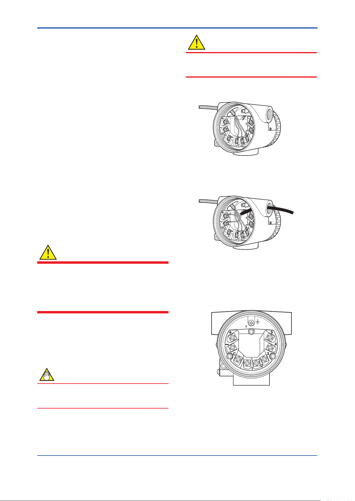
5.4 Cable and Terminal Connections
5.4.1 Input Terminal Connections
It is recommended that the terminals be
connected in the order of input terminal (1) and
output terminal (2).
Figure 5.4 Terminal Connection Pro cedure
The temperature sensor is to be
connected as shown in Figures 5.6 and
5.7.
Figure 5.5 Terminal diagram
Page 26
<5. Wiring>
F0506.ai
1
2
3
4
5
1
2
3
4
5
1
2
3
4
5
1
2
3
4
5
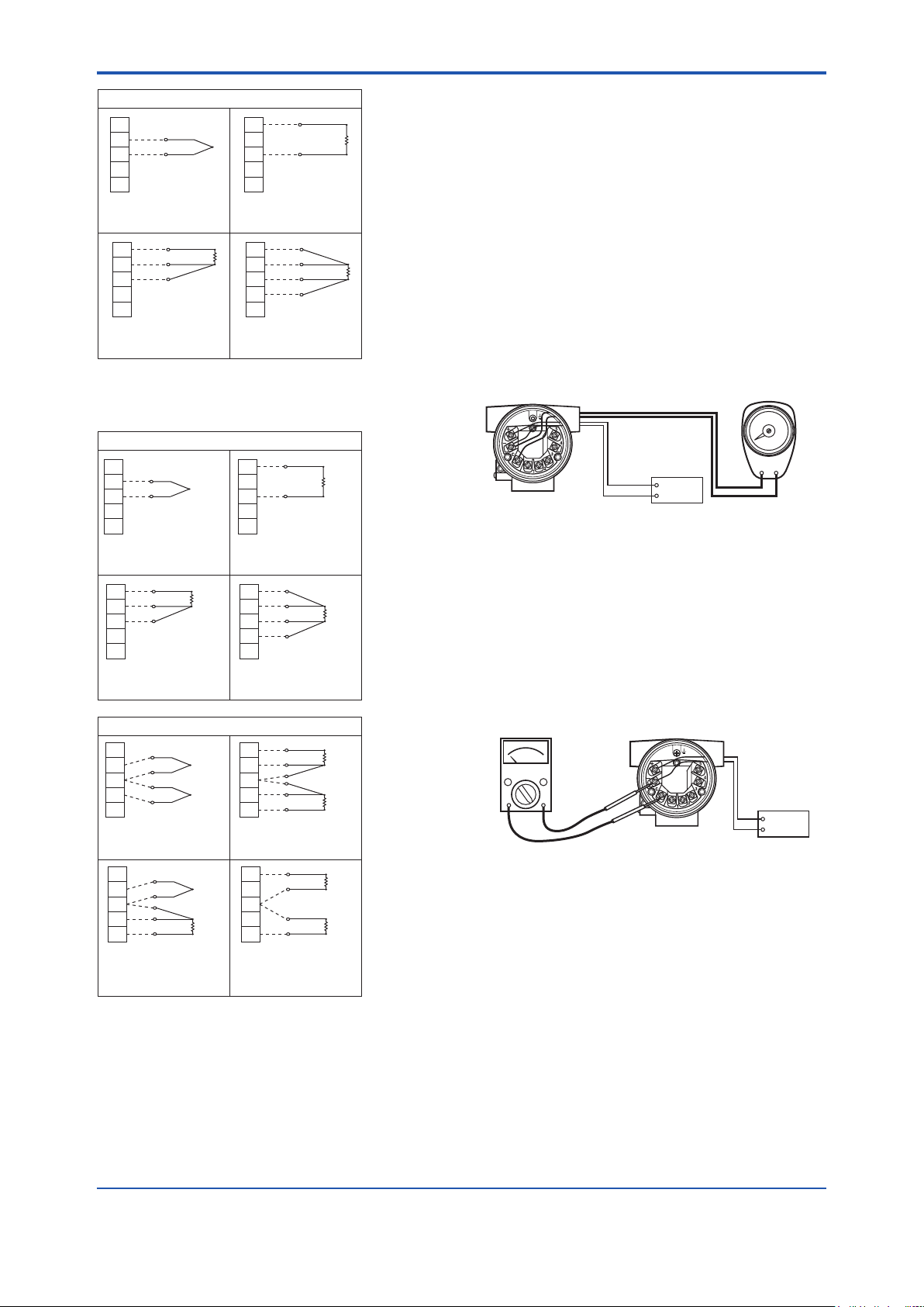
(–)
(+)
(B)
(A)
(B)
(A)
(B)
(B)
(A)
(A)
(B)
Thermocouple and
DC voltage
RTD and resistance
(2-wire)
RTD and resistance
(3-wire)
RTD
(4-wire)
Sensor1(YTA110, YTA310)
(B1)
(A1)
1
2
3
4
5
(–)
(+)
1
2
3
4
5
(B1)
(B1)
1
2
3
4
5
(–)
(+)
1
2
3
4
5
(+)
(A1)
(B2)
(B2)
(A2)
(A)
(B)
(B)
(B2)
(A2)
1
2
3
4
5
1
2
3
4
5
1
2
3
4
5
1
2
3
4
5
(–)
(+)
(B)
(A)
(B)
(B)
(B)
(A)
(A)
(A)
(B)
Thermocouple and
DC voltage
RTD and resistance
(3-wire)
Thermocouple +
RTD and resistance
(3-wire)
RTD and resistance
(2-wire)
2 input (YTA320)
Thermocouple and
DC voltage
RTD and resistance
(2-wire)
RTD and resistance
(3-wire)
RTD
(4-wire)
1 input (YTA320)
F0507.ai
F0508.ai
Field indicator
Power
supply
––+
+
F0509.ai
Check meter
+
–
Power
supply
5.4.2 Output Terminal Connection
(1) Connection of output signal/power supply
cable
Connect the output signal cable (shared with the
power supply cable) to the – terminal and the +
terminal. For details, refer to Figure 5.2, “Loop
construction”.
) Connectionofwiringforeldindicator
(2
Connect the lead wire for the eld indicator with the
– terminal and the C terminal.
Note: Use a eld indicator with an internal resistance of 10Ω or
less.
Figure 5.6 YTA110 and YTA310 Input Terminal
Wire Connection Diagram
5-3
Figure 5.8 Connection to Field Indicator
(3) Connectionofcheckmeter
Connect the check meter with the – terminal and
the C terminal.
The current signal of output signal 4 to 20 mA DC is
output from the – terminal and the C terminal.
Note: Use a check meter with internal resistance of 10Ω or less.
Figure5.9 CheckMeterConnection
Figure 5.7 YTA320 Input Terminal Wire Connection
Diagram
IM 01C50B01-01E
Page 27

<5. Wiring>
5-4
IM 01C50B01-01E
F0510.ai
Apply a nonhardening
sealant to the threads for
waterproofing.
Wiring conduit
Tee
Flexible fitting
Drain plug
F0511.ai
Flameproof packing adapter
Apply a nonhardening
sealant to the threads for
waterproofing.
Wiring conduit
Tee
Flexible fitting
Drain plug
CAUTION
5.5 Wiring Cautions
(1) General-use Type and Intrinsically Safe
Type
Use metal conduit wiring or a waterproof gland
(metal wiring conduit JIS F 8801) for cable wiring.
ply nonhardening sealant to the threads of
• Ap
the wiring tap and a exible tting for secure
waterproong. Figure 5.10 shows an example
of wiring on the output side. This example also
applies to the wiring on the input side.
Figure 5.10 Example of Wiring Using a Wiring
(2) TIIS Flameproof Type
Wire cables through a ameproof packing adapter,
or using a ameproof metal conduit.
Wiringcablethroughameproofpacking
■
adapterforonlyTIISameprooftype(see
Figure 5.11)
• Use only ameproof packing adapters
approved by Yokogawa.
• Ap
box connection port and to the threads on the
ameproof packing adapter for waterproong.
Conduit
ply a nonhardening sealant to the terminal
• Measure the cable outer diameter in two
directions to within 0.1mm.
• Calculate the average of the two diameters, and
use packing with an internal diameter nearest to
this value from among the three provided (see
Table 5.1).
Table5.1 FlameproofPackingandAppropriate
Wiring Port
Thread
Diameter
G1/2
Cable Outer Diameters
Appropriate
Cable Outer
Diameter
(mm)
8 - 10
10.1 - 121616
Identifying
Mark
10 - 12
8 - 10
Part
Number
G9601AM
Follow the procedure below to install the ameproof
packing adapter.
1. Screw the ameproof packing adapter into
the terminal box until the O-ring touches the
terminal box wiring port (at least 6 full turns),
and tighten the lock nut.
nsert the cable through the union cover, the
2. I
union coupling, the gland the clamp nut, the
clamp ring, one washer, the rubber packing,
and the packing box, in that order.
3. Insert the end of the cable into the terminal box.
4. Tighten the union cover to grip the cable.
When tightening the union cover, tighten
approximately one turn past the point where
the cable will no longer move up and down.
Proper tightening is important. If it is too tight, a
circuit break in the cable may occur; if not tight
enough, the ameproof effectiveness will be
compromised.
Tighten the union cover approximately one turn
after the point where you can no longer shift
the cable up and down by hand. Take great
care in this step, since proper tightening is very
important.
Figure 5.11 Typical Cable Wiring Using Flameproof
PackingAdapter
5. Fasten the cable with tightening the clamp nut.
6. Tighten the lock nut on the union cover.
7. Connect the cable wires to each terminal.
Page 28

<5. Wiring>
Adapter body
Rubber packing
Washer
Packing box
Grand
Clamp ring
Clamp nut
Union coupling
Union cover
O-ring
Lock nut
Lock nut
Cable
Be sure to apply
non-hardening sealant to the
threads for water proofing.
F0512.ai
CAUTION
F0513.ai
Non-hazardous
area
Hazardous
area
Flameproof
heavy-gauge
steel conduit
Tee
Drain plug
Gas sealing
device
Flameproof flexible
metal conduit
Apply a nonhardening
sealant to the threads of
these fittings for
waterproofing
Seal fitting
After wiring, impregnate the fitting
with a compound to seal tubing.
WARNING
F0514.ai
Grounding
terminal
(Inside)
Grounding
terminal
(Outside)
5.6 Grounding
Grounding is always required for the proper
operation of transmitters. Follow the domestic
electrical requirements as regulated in each
country. For a transmitter with built-in lightning
protector, grounding should satisfy ground
resistance of 10Ω or less.
Ground terminals are located on the inside and
outside of the terminal box. Either of these terminals
may be used.
5-5
Figure5.12 FlameproofGlandPackingAdapter
lnstallation
■ Flameproofmetalconduitwiring
• A seal tting must be installed near the terminal
box connection port for a sealed construction.
ply a nonhardening sealant to the threads of
• Ap
the terminal box connection port, exible metal
conduit and seal tting for waterproong.
For TIIS flameproof type and intrinsically safe,
grounding should satisfy Class D requirements
(grounding resistance, 100Ω or less).
Figure 5.14 Grounding Terminal
Figure 5.13 Typical Wiring Using Flameproof Metal
Conduit
IM 01C50B01-01E
Page 29
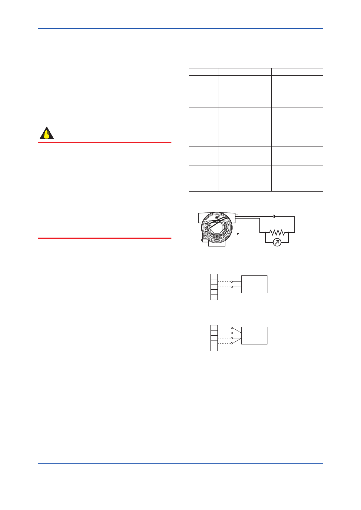
<6. Maintenance>
IMPORTANT
F0601.ai
1
2
3
4
5
1
2
3
4
5
(A)
(B)
(B)
(A)
a. Wiring of power supply and output
b. Example of wiring for thermocouple or DC voltage input
(when 1 input type is used)
+ Output signal
– Load
resistance
DC voltage generator
Voltmeter
c. Example of wiring for thermometer resistor 4-core type
(when 1 input type is used)
Variable resistor
(+)
(–)
6. Maintenance
6-1
6.1 General
Each component of this instrument is congured in
units to make maintenance easier.
This chapter contains disassembly and assembly
procedures associated with calibration, adjustment
and part replacement required for maintenance of
the affected instrument.
1. Maintenance of this instrument should be
performed in a service shop where the
necessary tools are provided.
2. Handling the CPU assembly
Some of the parts contained in the CPU
assembly are susceptible to static electricity
damage. Before performing maintenance,
use a ground wrist band or other antistatic
mea sures, and avoid touching the electronic
components and circuits with bare hands.
When removed from the instrument, keep
the CPU assembly in an antistatic bag.
Table 6.1 Calibration Equipment List
Name Recommended Remark
Power
supply
Load
resistance
Voltmeter Model 1271
Universal
calibrator
Variable
resistor
SDBT, SDBS type
distributor
2792 type standard
resistor
(250Ω ±0.005%)
digital multimeter
(accuracy: ±0.002%)
Model 9100 type For calibration of
279301 type 6-dial
variable resistor
(accuracy: ±0.001%
±2mΩ)
4 to 20mA DC
(Output voltage:
26.5±1.5V, drop
by internal 250Ω
resistance included)
For 4 to 20mA DC
For 4 to 20mA DC
signal
DC voltage and
thermocouple
For calibration
of thermometer
resistor (RTD) input
6.2 Calibration
This instrument is fully factory-tested and is
guaranteed for the intended accuracy, eliminating
the need for calibration. When calibration needs to
be varied, the following equipment and calibration
procedure is recommended.
6.2.1 Selection of Equipment for Calibration
Table 6.1 lists the equipment required for
calibration. The calibration equipment traceable to a
verifying agency standard should be used.
6.2.2 Calibration Procedure
To conduct calibration required to evaluate the
uncertainty while using the instrument, follow the
steps below:
1. In accordance with the example wiring shown in
Figure 6.1, connect each equipment and initiate
warm up. Lay wiring on the input side according
to the sensor to be used.
Figure 6.1 Example of Wiring for Calibration
Equipment
2. For DC voltage input
With a voltage generator, deliver input signals
corresponding to 0, 25, 75, or 100% of the input
span to the temperature transmitter. Measure
the resulting input signal with the voltmeter
(digital multimeter) and check the output value
relative to the input value.
IM 01C50B01-01E
Page 30
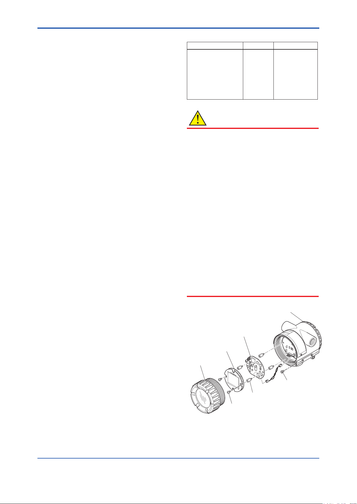
<6. Maintenance>
6-2
IM 01C50B01-01E
CAUTION
F0602.ai
Terminal cover
Lock bolt
CPU assembly
Stud bolt
Mounting screw
Amp. Cover
LCD board
(with indicator)
3. For thermocouple input
Since this instrument is equipped with a
reference junction compensating function, use
a reference junction compensating function
in universal calibrator in order to compensate
for this function upon calibration. According to
the reference milivolt table for thermocouple,
obtain milivolt corresponding to 0, 25, 50, 75,
or 100% of the span, and use that power as the
input value, then deliver it from the universal
calibrator to the temperature transmitter.
Measure the resulting output signal with the
voltage meter (digital multimeter) and check the
output value relative to the input value.
4. Thermometer resistor (RTD)
Using a thermometer resistor as input,
calibration of the temperature transmitter is
carried out via a 4- core wire connection.
As dened the reference resistor value table
of the thermometer resistor (RTD), obtain
resistance values corresponding to 0, 25, 50,
75 or 100% of the span, and use the obtained
resistance as the input value, then deliver it
to the temperature transmitter by means of a
variable resistor. Measure the resulting output
signal with the voltmeter (digital multimeter)
and check the output value relative to the input
value.
5. In Steps 2 through 4, if the output signal
deviates from the given range of accuracy
when a given input signal is delivered, adjust
the output using the handheld terminal. For
details of how to adjust the output, refer to
the additional references, “BRAIN Protocol”
IM 01C50T03-01E or “HART Protocol” IM
01C50T01-01E and the instruction manual for
each terminal.
Table 6.2 Tools for Disassembly and Assembly
Tool name Quantity Remark
Phillips screwdriver
Standard screwdriver
Hexagonal wrench
Crescent wrench
Torque wrench
Box wrench
Box screwdriver
Forceps
1
1
1
1
1
1
1
1
For M10 screw
Precautions for ATEX, IECEx and TIIS
Flameproof Type Transmitters
• For a withstand ameproof type transmitter,
as a rule, move the transmitter to a nonhazardous location, then proceed with
maintenance and restore the instrument to
the original condition.
r a withstand ATEX, IECEx and TIIS
• Fo
ameproof type transmitter, turn the lock
bolt (hexagon socket bolt) clockwise with
a wrench for hexagon head, unlock and
remove the cover. When installing the
cover, it is the must to turn the lock bolt
counterclockwise and lock the cover (locked
to a torque of 0.7 Nm).
• For a withstand ameproof type transmitter,
in no case should the user be allowed to
modify the transmitter. Therefore, no user
is allowed to add a built-in indicator, or use
the transmitter with the indicator removed.
Contact us for any modication.
6.3 Disassembly and Assembly
This section details the procedure for part
replacement or disassembly and assembly of
each component depending on the maintenance
process.
Before starting disassembly and assembly work,
turn off the power, and use a tool suited to the
associated work.
Table 6.2 lists the tools required for disassembly
and assembly of the instrument.
Figure 6.3 Mounting and Removal of Built-in
Indicator and CPU Assembly
Page 31

<6. Maintenance>
F0603.ai
NOTE
IMPORTANT
6-3
6.3.1 Replacement of Built-in Indicator
Removal of built-in indicator
1. Remove the cover.
2. Loosen two mounting screws while using your
hand to support the built-in indicator.
3. Remove the LCD assembly from the CPU
assembly. At this time, straighten and pull the
LCD assembly forward so that the connector
connecting the CPU assembly and the LCD
assembly is not damaged.
Mounting the built-in indicator
Integral Indicator can be installed in the following
three directions.
6.3.2 Replacement of CPU Assembly
Removal of CPU assembly
1. Remove the cover.
2. Use a Phillips screwdriver to loosen the two
screws.
3. For a CPU assembly with a built-in indicator,
remove it as described in Section 6.3.1. Next
loosen the two stud bolts.
4. Pull the CPU assembly directly toward you.
5. Remove the cable (with a brown connector
attached at the head).
Use care not to apply excessive force to the CPU
assembly during removal.
Mounting the CPU assembly
1. Connect the cable with the CPU assembly.
2. Align the pin on the base board with the
connector (black) of the CPU assembly, and
insert the CPU assembly straight into the board.
Figure 6.4 Installation Direction of Indicator
1. Place the LCD assembly in desired direction
over the CPU assembly.
2. Align the mounting hole of the LCD assembly
with the stud bolt hole, and carefully insert the
indicator into the connector in a straight manner
so that the connector is not damaged.
3. Tighten the two mounting screws that secure
the indicator.
4. Install the cover.
Use care not to pinch the cable under the cover,
and fully insert the cable into the case.
3. Loosen the two screws. If the unit includes a
builtin indicator, install it as described in Section
6.3.1.
ount the cover.
4. M
IM 01C50B01-01E
Page 32

<6. Maintenance>
6-4
IM 01C50B01-01E
YES
YES
NO
NO
F0604.ai
Measured value
is found faulty
Error in process
variable?
Faulty
area in measurement
system
Receiver error
Operating requirements:
check, study, correction
Check the transmitter
Environmental condition:
check, study, correction
Environmental condition
Operating requirements
Error in measurement
system
Transmitter
Inspect receiver
Inspect the process
: Part supported
by self-diagnosis
F0605.ai
YES
NO
NO
YES
NO
YES
NO
NO
YES
YES
Was a faulty
area found with self-
diagnosis?
Is the polarity
of the power supply
correct?
Are the power
supply voltage and load
resistance correct?
Is the sensor
correctly connected?
Is there a
disconnection in the loop?
Do the loop numbers
correspond to the
counterpart?
The following phenomena indicate that this
instrument may be out of operation.
[Example]
• No output signal is delivered.
• Process variable changes but the output
signal remains unchanged.
• The assessed value of the process variable
and the output are not coincident.
Refer to our service personnel for details.
• If a built-in indicator is attached, check the
display of the error code.
• Connect a hand-held terminal and check
self-diagnosis.
Refer to the error message list and
check for recovery measures.
Check the polarity between the
power supply and terminal box and
correct it.
Refer to Section 5.2 and set
the specified voltage and load
resistance.
Check the sensor connection and
correct it.
Check for disconnection or faulty
wiring and take corrective
measures.
6.4 Troubleshooting
When the measured value is found abnormal,
follow the troubleshooting owchart below. If the
complex nature of the trouble means that the cause
cannot be identied using the following owchart,
refer the matter to our service personnel.
6.4.1 Basic Troubleshooting Flow
When the process measurement is found to be
abnormal, it is necessary to determine whether
the input temperature is out of range, the sensor
has failed or being damaged, or the unit has
been improperly wired. If it is suspected that the
measurement system is the source of the problem,
use the owchart to identify the affected area and
determine how to proceed.
In these troubleshooting steps, the self diagnostic
function provides helpful solutions to the problem,
refer to the instructions in Section 6.5 for details.
6.4.2 Example of Troubleshooting Flow
Figure 6.5 Basic Flow and Self-diagnosis
Figure 6.6 Example of Troubleshooting Flow
Page 33

<6. Maintenance>
Table 6.3 Problems, Causes and Countermeasures
Observed
Problems
Output uctuates
greatly.
Possible Cause Countermeasure
Span is too narrow. Check the range, and
change the settings to make
(BRAIN protocol) (HART protocol)
F10:LRV
F20:URV
Related Parameter
the span larger.
J05:SNSR1 CLR
K05:SNSR2 CLR
L05:OUT CLR D/A Clr to Default
G10:OUTPUT MODE Loop test (122)
J05:SNSR1 CLR
K05:SNSR2 CLR
L05:OUT CLR D/A Clr to Default
F10:LRV
F20:URV
H10:REVERSE OUT —
H40:WRITE PROTCT Chng wrt Protect
B10:PV is
B20:SV is
D10:SENSOR1 TYPE
E10:SENSOR2 TYPE
Transmitter
outputs xed
current.
Output is reversed.
(See note 1)
Parameters cannot
be changed.
Sensor backup
function doesn’t
work correctly.
Input adjustment by
user was not corrctly
done.
Output adjustment by
user was not correctly
done.
The transmitter is in
manual (test output)
mode.
Input adjustment by
user was not corrctly
done.
Output adjustment by
user was not correctly
done.
LRV is greater than
URV.
The transmitter is set to
reversed output mode.
The transmitter is in
write protect status.
Settings of Process
Variables are not
correct.
Conguration of
Sensor1 and Sensor2 is
not correct.
Clear the user adjustment
(Sensor trim) value or set it
to off.
Clear the user adjustment
(output trim) value or set it
to off.
Release manual mode.
(Make the transmitter return
to Automatic Mode)
Clear the user adjustment
(Sensor trim) value or set it
to off.
Clear the user adjustment
(output trim) value or set it
to off.
Set the correct value to URV
and LRV.
Set the transmitter to normal
output mode.
Release write protect.
Set Sensor1 as PV and
Sensor2 as SV.
• Ch
eck the type and wire
settings for Sensor1 and
Sensor2.
• Check the connection of
Sensor1 and Sensor2.
F40:BURN OUT Sensor barnout
H20:SNSR BACKUP Snsr backup (14141)
B12:PV DAMPING PV damp (1322)
B13:DMP POINT PV damp point
Output damping
doesn’t work.
Sensor Burnout is set
to “off.”
Sensor backup mode is
not enabled.
Damping time constant
is set to “0 second.”
Setting for “PV damping
point” is too small.
Check the Sensor Burnout
setting.
Change the Sensor Backup
function to “enable.”
Set correct value.
If output uctuation is great,
set a greater value for PV
damping point than current
setting. (Initial setting is “2%”
of output)
Note 1: If the reversed output is desired and necessary setting was done by user, it is not considered as a problem.
6-5
PV LRV (4)
PV URV (5)
Snsr1 Trim Act
(123312)
Snsr2 Trim Act
(123322)
(12343)
Snsr1 Trim Act
(123312)
Snsr2 Trim Act
(123322)
(12343)
PV LRV (4)
PV URV (5)
(Hot key)
PV is (11211)
SV is (11212)
Snsr1 cong (134)
Snsr2 cong (135)
(14315)
(1323)
IM 01C50B01-01E
Page 34

<6. Maintenance>
6.5 Integral Indicator and Error Display
For temperature transmitters equipped with an
integral indicator, errors in the temperature sensor
or the transmitter cause an integral indicator to call
up the applicable error code. Table 6.4 lists the error
codes and the associated corrective actions.
Table 6.4 List of Error Codes
Indicator BT200 display Cause Output operation upon error Action
N/A Good
Er-01 Output Too Low Input value is lower than the PV low
range value.
Er-02 Output Too High Input value is higher than the PV
upper range value.
Er-03 Sensor1 Failure Sensor1 fails or disconnects from
the terminal block.
Er-04 Sensor2 Failure
(YTA320 only)
Er-05 S1 Signal Error Sensor1 input value greatly exceeds
Er-06 S2 Signal Error
(YTA320 only)
Er-07 Amb Temp Low The ambient temperature exceeds
Er-08 Amb Temp High The ambient temperature exceeds
Er-09 Sns Backup Start
(YTA320 only)
Er-10 Illegal PV MAP There is a problem with the PV
Er-11 Term Sns Failure Terminal block temperature sensor
Er-12 EEPROM Failure EEPROM failed. The output goes to the value
Er-13 CPU Failure Output side hardware failure. The output goes to the value
Er-14 AD Conv Failure Input circuit hardware failure. The output goes to the value
Er-15 Reverse Cal Fail Conrmation Calculation result is
Sensor2 fails or disconnects from
the terminal block.
the sensor measurement range.
Sensor type setting or connection
polarity may be incorrect.
Sensor2 input value greatly exceeds
sensor measurement range. Sensor
type setting or connection polarity
may be incorrect.
the lower ambient temp limit and
the specied accuracy cannot be
achieved.
the upper ambient temp limit and
the specied accuracy cannot be
achieved.
Sensor backup mode is in effect. Sensor2 input is used as
mapping settings.
failed.
bad.
Output goes to minimum
value(–2.0%).
Output goes to maximum
value(105%).
If sensor1 is set as PV, the
burnout value is output.
When sensor backup mode is
set in YTA320, sensor2 input
is used as output.
If sensor2 is set as PV, or
sensor backup mode is in
effect, sensor burnout value is
output.
Output goes to minimum
value(–2.0%) or maximum
value(105%).
Output goes to minimum
value(–2.0%) or maximum
value(105%).
Continues to operate and
output.
Continues to operate and
output.
output. If sensor2 also fails,
the transmitter operate with
burnout settings.
Output status immediately
before error is retained
(HOLD).
Operation and output
continues.
set by the hardware failure
mode jumper.
set by the hardware failure
mode jumper.
set by the hardware failure
mode jumper.
The output goes to the value
set by the hardware failure
mode jumper.
Check the LRV setting and
adjust.
Check the URV setting and
adjust.
• Check sensor for damage.
• Check terminal connection.
• If sensor backup mode is set,
refer to “Er-09”.
• Check sensor for damage.
• Check terminal connection.
• If sensor backup mode is
set, repair wiring or replace
damaged sensors.
• Check sensor connections.
• Check the sensor type
selected.
• Check sensor connections.
• Check sensor type selected.
Use a heater to raise the
ambient temperature, or reset
to a higher level.
Take enough distance from the
source of heat, or reset to a
lower level.
Restore the status of sensor1
to normal and Enable sensor1
return parameters, or turn the
power ON again.
Check the setting for PV
mapping and correct the
setting.
Contact our service personnel.
Contact our service personnel.
Contact our service personnel.
Contact our service personnel.
Contact our service personnel.
6-6
IM 01C50B01-01E
Page 35

<7.GeneralSpecications>
7. GeneralSpecications
7-1
7.1 StandardSpecications
For the specications of Fieldbus communication
type marked with (◊), refer to IM 01C50T02-01E.
Input signal:
Input points: YTA110; 1, YTA310; 1, YTA320; 2
Thermocouple (T/C):
J, K, E, T, R, S, B, N (JIS/IEC584), L, U
(DIN43710), W3, W5 (ASTM988)
Thermometer resistor (RTD):
Pt100, Pt200, Pt500 (IEC751), JPt100(JIS),
Cu, Ni120 2/3/4-wire
DC voltage: mV
Resistance: Resistor 2/3-wire
Input signal source resistance:
1kΩ or lower (at thermocouple, DC voltage
input)
Input lead wire resistance:
10Ω/1-core or less (with thermometer resistor,
resistance input)
Output(◊):
Two wire 4 to 20 mA DC
Output range: 3.68 mA to 20.8 mA
Measuring range:
Refer to Table 7.1.
wersupplyvoltage(◊):
Po
For general use type;
10.5 to 42 VDC
With lightning protection (Optional code A);
10.5 to 32 VDC
For intrinsically safe, Type n, non-incendive or
non-sparking type;
10.5 to 30 VDC
mmunicationlineconditions(◊):
Co
Power supply voltage; 16.4 to 42 VDC
Load resistance; 250 to 600Ω (including cable
resistance)
For relation between power supply voltage and
load resistance, refer to Figure 5.3.
Maximum line length; 2 km when CEV cable is
used.
Load resistance; 0.22 μF or less
Load inductance; 3.3 mH or less
Spacing to power line;
Output signal line; 15 cm or longer (avoid
parallel wiring)
Input signal line; 100 cm or longer (avoid
parallel wiring)
Input impedance of receiver connected to
receiver resistance; 10 kΩ or higher (at 2.4 kHz)
Accuracy(◊):
YTA110;
A/C conversion accuracy + D/A conversion
accuracy (Refer to Table 7.1) or ±0.1%,
whichever is greater. For thermocouple input,
above plus reference junction compensation
accuracy.
YTA310, YTA320;
A/C conversion accuracy + D/A conversion
accuracy (Refer to Table 7.1) For
thermocouple input, above plus reference
junction compensation accuracy.
Reference junction compensation accuracy:
±0.5°C (±0.9°F)
Ambient temperature:
–40 to 85°C (–40 to 185°F) . . . .general type
–30 to 80°C (–1 to 176°F) . . . . .with Integral
indicator
Am
bienttemperatureeffectper10°Cchange(◊):
YTA110;
±0.1% or ± (Temperature Coefcient/span),
whichever is greater (refer to Table 7.2)
YTA310, YTA320;
A/D conversion temperature factor + D/A
conversion temperature factor
(refer to Table 7.3)
Stability
RTD:
±0.1% of reading or ±0.1°C per 2 years,
whichever is greater at 23±2°C.
T/C:
±0.1% of reading or ±0.1°C per year,
whichever is greater at 23±2°C.
5 Year Stability
RTD:
±0.2% of reading or ±0.2°C,
whichever is greater at 23±2°C.
T/C:
±0.4% of reading or ±0.4°C,
whichever is greater at 23±2°C.
Ambient humidity:
5 to 100%RH at 40°C (104°F)
IM 01C50B01-01E
Page 36

<7.GeneralSpecications>
7-2
IM 01C50B01-01E
Effectofsupplyvoltageuctuation:
±0.005%/V
Insulation:
Input/output insulated at 500 V DC
Mounting:
Mounted on 2B pipes and wall
Degrees of Protection:
IP66/IP67, NEMA 4X
Electrical connection:
Refer to “Model and Specication Codes”.
Case and cover:
Aluminum alloy casting
Painting:
Polyurethane resin baked nish
Deep sea moss green (equivalent of Munsell
0.6GY3.1/2.0)
Integral indicator (option):
LCD digital indicator (5-digit display)
Output bar graph; 0 to 100% display
Damping constant:
0 to 99 seconds (integer range that can be set)
Sensor burnout (Output Signal Code D&E) :
High (110%, 21.6 mA DC) or Low (–2.5%, 3.6
mA DC)
Weight:
1.2 kg; without built-in indicator (without
mounting bracket)
1.4 kg; with Integral indicator (without mounting
bracket)
EMC compliant standard:
,
EN61326, AS/NZS CISPR11
Material Cross Reference Table
SUS304 AISI 304
SUS316 AISI 316
Page 37
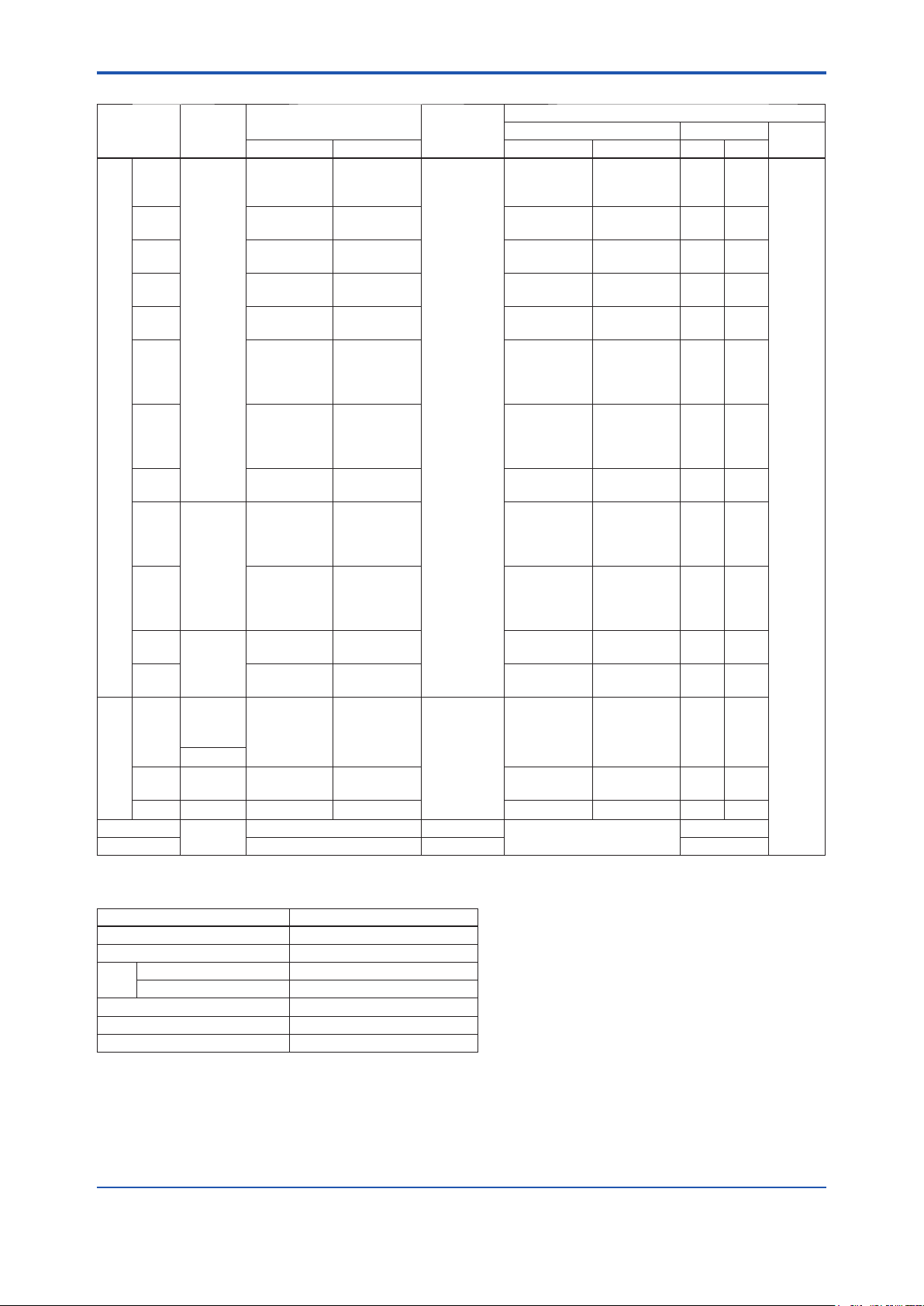
<7.GeneralSpecications>
Table 7.1 Input Type, Measurement Range and Accuracy
212
572
752
-328
-58toto
-328
-58toto
-328
-58toto
-328
-58toto
-58
32
212
1112
-58
32
212
1112
-328
-58toto
32
752
2552
3632
32
752
2552
3632
-328
-58toto
-328
-58toto
-328
-328
-328
-328
-94
-40toto
Accuracy
to
572
to
752
to
3308
-58
1832
-58
2192
-58
2502
-58
2372
to
32
to
212
to
1112
to
3214
to
32
to
212
to
1112
to
3214
-58
752
to
752
to
2552
to
3632
to
4172
to
752
to
2552
to
3632
to
4172
-58
1652
-58
1112
to
1562
to
1562
to
1562
to
932
-40
302
±3.0
±1.0
±0.75
±0.35
±0.16
±0.40
±0.20
±0.50
±0.25
±0.80
±0.35
±1.0
±0.80
±0.60
±0.40
±1.0
±0.80
±0.60
±0.40
±0.25
±0.14
±0.80
±0.50
±0.60
±0.90
±0.70
±0.50
±0.70
±0.90
±0.30
±0.20
±0.50
±0.25
±0.14
±0.30
±0.20
±0.16
±1.35
±1.0
(Recommended)
1562
1562
1562
932
Minimum
Span
25°C
(45°F)
10°C
(18°F)
100
to
300
to
400
to
-200
-50toto
-200
-50toto501200
-200
-50toto
-200
-50toto
-50
to
0
to
100
to
600
to
-50
to
0
to
100
to
600
to
-200
-50toto
0
to
400
to
1400
to
2000
to
0
to
400
to
1400
to
2000
to
-200
-50toto
-200
-50toto
-200
to
-200
to
-200
to
-200
to
-70
-40toto
Input range A/D Accuracy
300
400
1820
-50
1000
-50
1372
-50
1300
0
100
600
1768
0
100
600
1768
-50
400
400
1400
2000
2300
400
1400
2000
2300
-50
900
-50
600
850
850
850
500
-40
150
—
Sensor Type
T/C
JPt100
RTD
mV
ohm 0 to 2000 [Ω] 20 [Ω] ±0.35 [Ω]
Reference
Standard
B
E -200 to 1000 -328 to 1832
J -200 to 1200 -328 to 2192
K -200 to 1372 -328 to 2502
N -200 to 1300 -328 to 2372
IEC584
R -50 to 1768 -58 to 3214
S -50 to 1768 -58 to 3214
T -200 to 400 -328 to 752
W3
ASTM
E988
W5 0 to 2300 32 to 4172
L
DIN43710
U -200 to 600 -328 to 1112
Pt100
Pt200
Pt500
Cu
Ni120 — -70 to 320 -94 to 608 -70 to 320 -94 to 608 ±0.11 ±0.19
IEC751
JIS C1604
SAMA
RC21-4
—
Measurement Range
°C °F °C °F °C °F
100 to 1820 212 to 3308
0 to 2300 32 to 4172
-200 to 900 -328 to 1652
-200
to
850
-328
to
-200
to
850
-328
to
-200
to
850
-328
to
-200
to
500
-328
to
-70 to 150 -94 to 302
-10 to 100 [mV] 3 [mV]
±1.35
±0.63
±0.29
±0.72
±0.36
±0.90
±0.45
±1.44
±0.63
±1.44
±1.08
±0.72
±1.44
±1.08
±0.72
±0.45
±0.25
±1.44
±0.90
±1.08
±1.62
±1.26
±0.90
±1.26
±1.62
±0.54
±0.36
±0.90
±0.45
±0.25
±0.54
±0.36
±0.29
±2.43
±12 [μV]
7-3
D/A
Accuracy
±5.4
±1.8
±1.8
±1.8
±0.02%
of span
±1.8
Table 7.2 YTA110 Effect of Ambient Temperature
Sensor Type TemperatureCoefcient
Thermocouples E, J, K, N, T, L, U 0.08°C + 0.02% of abs.reading
Thermocouples R, S, W3, W5 0.25°C + 0.02% of abs.reading
100°C ≤ Reading < 300°C 1°C + 0.02% of abs.reading
T/C B
300°C ≤ Reading 0.5°C + 0.02% of abs.reading
RTD 0.08°C + 0.02% of abs.reading
mV 0.002 mV + 0.02% of abs.reading
ohm 0.1Ω + 0.02% of abs.reading
te1: Ambient Temperature Effect per 10°C change is
o
N
±0.1% or ±(temperature coefcient/span), whichever
is greater.
No
te2: The “abs.reading” on Table7.2 means the absolute
value of the reading in °C.
Example of abs reading;
When the temperature value is 250 Kelvin, abs reading
is 23.15, absolute (250–273.15).
Example of Ambient Temperature Effect;
Conditions;
1) Input Sensor: Pt100
2) Calibration Range: –100 to 100°C
3) Reading value: –50°C
Ambient Temperature Effect per 10°C;
Temperature Coefcient/Span
=(0.08°C+0.02/100×|–50°C|)/{100°C–(–100°C)}
= 0.00045→ 0.045%
Therefore, Ambient Temperature Effect is ±0.1%/10°C
IM 01C50B01-01E
Page 38
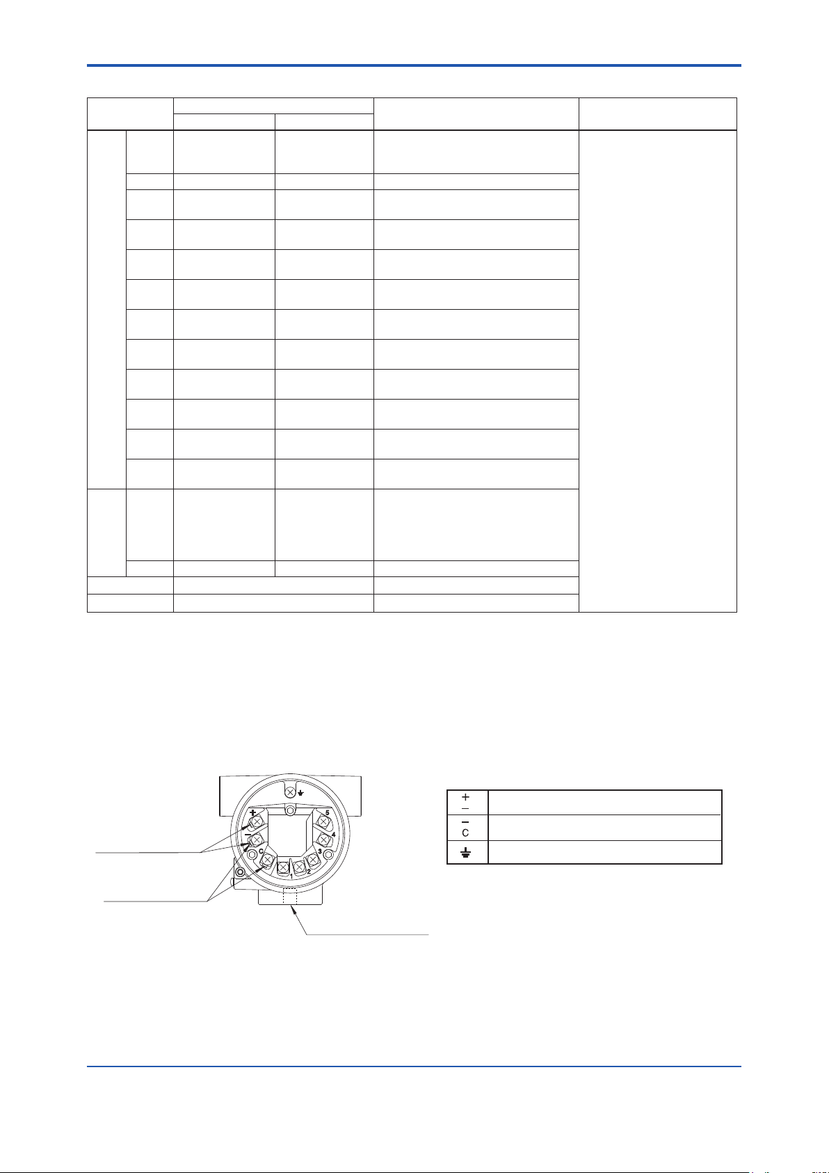
<7.GeneralSpecications>
7-4
IM 01C50B01-01E
F0702.ai
Power Supply and output terminal
External Indicator (ammeter) terminal
*1
Ground terminal
Terminal Configuration
Communication
Terminals (BT200 etc.)
Connection hook
CHECK METER
Connection hook
*1
*1: When using an external indicator or check meter,
the internal resistance must be 10Ω or less.
The hook is not available for Fieldbus
communication type(output signal code F).
M10×1.5 12-deep female
for mounting bracket
Table 7.3 YTA310, YTA320 Effect of Ambient Temperature
Sensor Type
100
B
E -200 to 1000 -328 to 1832 ± ( 0.035°C + 0.042 % of abs.reading)
J
K
N
R
T/C
S
T
W3
W5
L
U
Pt100
Pt200
Pt500
RTD
JPt100
Cu
Ni120 -70 to 320 -94 to 608 ± ( 0.016°C + 0.007 % of reading)
mV — ± (0.001mV + 0.0043 % of abs.reading)
ohm — ± ( 0.040Ω + 0.0088 % of reading)
300
1000
-2000to
-2000to
-2000to
-50
200toto
-50
200toto
-2000to
1400toto
1400toto
-2000to
-2000to
-200
-200
-200
-200
-70
Input Range
°C °F
to
300
to
1000
to
1820
1832
-32832toto32
to01200
-32832toto32
to01372
-32832toto32
to01300
200
1768
200
1768
-32832toto32
to0400
0
0
1400
2300322552toto
1400
2300322552toto
to0900
to0600
to
850
to
850
to
850
to
500
to
150
-32832toto32
-32832toto32
-328
-328
-328
-328
212
572
-58
392toto
-58
392toto
-94
to
572
± ( 0.530°C - 0.080 % of reading)
to
1832
± ( 0.350°C - 0.021 % of reading )
to
3308
± ( 0.140°C)
± ( 0.039°C + 0.020 % of abs.reading)
2192
± ( 0.039°C + 0.0029 % of reading)
± ( 0.046°C + 0.020 % of abs.reading)
2502
± ( 0.046°C + 0.0054 % of reading)
± ( 0.054°C + 0.010 % of abs.reading)
2372
± ( 0.054°C + 0.0036 % of reading)
392
± ( 0.210°C - 0.032 % of abs.reading)
3214
± ( 0.150°C)
392
± ( 0.210°C - 0.032 % of abs.reading)
3214
± ( 0.150°C)
± ( 0.046°C - 0.036 % of abs.reading)
752
± ( 0.046°C)
2552
± ( 0.100°C + 0.0040 % of reading)
4172
± ( -0.130°C + 0.020 % of reading)
2552
± ( 0.100°C + 0.0040 % of reading)
4172
± ( -0.120°C + 0.020 % of reading)
± ( 0.039°C + 0.020 % of abs.reading)
1652
± ( 0.039°C + 0.0029 % of reading)
± ( 0.046°C + 0.036 % of abs.reading)
1112
± ( 0.046°C)
to
1562
± ( 0.047°C + 0.009 % of reading)
to
1562
± ( 0.065°C + 0.012 % of reading)
to
1562
± ( 0.047°C + 0.009 % of reading)
to
932
± ( 0.047°C + 0.009 % of reading)
to
302
± ( 0.320°C + 0.120 % of reading)
DCoefcient D/ACoefeicient
A/
± {0.0088% of span + 0.007%
of (reading - LRV)}
Note: Temperature Effect = A/D coefeicnt + D/A coefcient (The data in the table is the coeffcient per 10°C change.)
Example 1; Pt100Ω, 0 to 200°C calibration range, 50°C reading
Example 2; T T/C, -100 to 100°C calibration range, 250°C reading
Terminals
(0.047°C + 50°C × 0.009%) + [200°C × 0.0088% + (50 - 0) × 0.007%]
= (0.047°C + 0.0045°C) + (0.0176°C + 0.0035°C )
= ± 0.0726°C [ per 10°C change ]
(0.046°C + | 250°C | × 0.036%) + {200°C × 0.0088% + [250 - (-100)] × 0.007%}
= (0.046°C + 0.018°C) + (0.0176°C + 0.0035°C )
= ± 0.0851°C [ per 10°C change ]
Page 39

<7.GeneralSpecications>
Factorysetting(◊)
Tag No. Left blank if not specied in order Unit of calibration range “°C” if not specied in order
Input sensor type “Pt100, 3-wire” if not specied in order Damping constant 2 seconds
Lower calibration range “0” if not specied in order Sensor burnout High side (110%, 21.6 mA DC)
Upper calibration range “100” if not specied in order Output when transmitter fails High side (110%, 21.6 mA DC) *
*1: When option code C1 is specied, Low takes effect (–2.5%, 3.6 mADC).
*2: When option code C1 is specied, Low takes effect (–5%, 3.2 mADC or less).
7.2 ModelandSufxCodes
Model BasicSpecicationCodes Description
YTA110
YTA310
YTA320
Output
signal
— A· · · · · · · · · · · · · · · · · · Always A
Electrical connection 0 · · · · · · · · · · · · · ·
Built-in indicator D· · · · · · · · · · ·
Mounting bracket B· · · · · · ·
Additional specications
*1: Use bolts for wall mounting.
· · · · · · · · · · · · · · · · · · · · · ·
· · · · · · · · · · · · · · · · · · · · · ·
· · · · · · · · · · · · · · · · · · · · · ·
-D · · · · · · · · · · · · · · · · · · · ·
-E · · · · · · · · · · · · · · · · · · · ·
-F · · · · · · · · · · · · · · · · · · · ·
2 · · · · · · · · · · · · · ·
3 · · · · · · · · · · · · · ·
4 · · · · · · · · · · · · · ·
N· · · · · · · · · · ·
D· · · · · · ·
J · · · · · · ·
K· · · · · · ·
N· · · · · · ·
/
Temperature transmitter (1 input type)
High precision temperature transmitter (1 input type)
High precision temperature transmitter (2 input type)
4 to 20mA DC output, BRAIN communication type
4 to 20mA DC output, HART communication type
FOUNDATION Fieldbus communication type (YTA320 only)
G1/2 female
1/2 NPT female
Pg13.5 female
M20 female
Digital indicator
None
SUS304 Stainless steel 2-inch horizontal pipe mounting *
SUS304 Stainless steel 2-inch vertical pipe mounting *
SUS316 Stainless steel 2-inch horizontal pipe mounting
SUS316 Stainless steel 2-inch vertical pipe mounting
None
Additional specications
1
1
*1
*1
7-5
1
*
2
7.3 OptionalSpecications
Item Descriptions Code
Lightning protector Power supply voltage: 10.5 to 32 V DC
Allowable current: Max. 6000A(1×40μs), repeating 1000A(1×40μs) 100 times
Painting Coating change Epoxy resin coating
Color change Amplier cover only Munsell renotation code: NI1.5 Black
Munsell renotation code: 7.5BG4/1.5, Jade green
Metallic silver
Amplier and Terminal covers Munsell renotation code: 7.5R4/14 Red
SUS316 exterior parts Exterior parts on the amplier housing (name plates, tag plate, screws)
will become SUS316 stainless steel
Stainless Steel Housing*
Wired tag plate SUS304 stainless steel tag plate wired onto transmitter
Calibration Unit Addition of Degree F and Degree R unit
Output signal low-side in
Transmitter failure*
NAMUR NE43
compliant*
Data Conguration*
Sensor matching function*
*1 : Not applicable with other option codes, except for A, C1, D2 and CM1.
*2 : Not applicable for output signal code F.
*3 : This specication is not included in option code E1. Select HC for SUS316 exterior parts regardless of E1.
*4 : When HC is selected, the material is SUS316 stainless steel.
2
1
Housing Material: SCS14A Stainless steel
2
2
Output signal low-side: –5 %, 3.2 mA DC or less.
Sensor burnout is also set to ‘Low’: –2.5 %, 3.6 mA DC
Output signal limits:
3.8 mA to 20.5 mA
Description into “Descriptor” parameter of HART protocol. (max. 16 characters)
2
RTD Sensor matching function
Failure alarm down-scale: output status at CPU failure and
hardware error is –5%, 3.2 mA or less.
Sensor burnout is also set to ‘Low’: –2.5%, 3.6 mA
Failure alarm up-scale: output status at CPU failure and
hardware error is 110%, 21.6 mA or more.
Sensor burnout is also set to ‘High’: 110%, 21.6 mA
*3
*4
A
X1
P1
P2
P7
PR
HC
E1
N4
D2
C1
C2
C3
CA
CM1
YTA110
×
YTA310
YTA320
IM 01C50B01-01E
Page 40

<7.GeneralSpecications>
7-6
IM 01C50B01-01E
[For Explosion Protected Types]
For FOUNDATION Fieldbus explosion protected type, see IM 01C50T02-01E.
Item Descriptions Code
ATEX
Canadian Standards
Association (CSA)
Factory Mutual (FM)
Japanese Industrial
Standards (TIIS)
Attached ameproof
packing adapter
IECEx
*1 : Applicable for Electrical Connection Code 2 and 4.
*2 : Applicable for Electrical Connection Code 2.
*3 : Not applicable for Output Signal Code F.
*4 : If cable wiring is to be used to a TIIS ameproof type transmitter, do not fail to add the YOKOGAWA-assured ameproof packing
adapter.
*5
: Applicable for Electrical connection code 2 and 4.
ATEX Intrinsically safe “ia”, Flameproof approval and Intrinsically safe “ic”
Electrical Connection: 1/2 NPT female and M20 female
*1
CSA Intrinsically safe, non-incendive and Explosionproof approval combination
Electrical Connection: 1/2 NPT female
*1
FM Explosionproof approval
Electrical Connection: 1/2 NPT female
*2
FM Intrinsically safe, non-incendive and Explosionproof approval combination
Electrical Connection: 1/2NPT female
*2
TIIS Flameproof approval
Electrical connection: G1/2 female
*4
Applicable cable: O.D. 8.5 to 11 mm
IECEx Intrinsically safe, Flameproof and Dust ignition proof Approval
Enclosure: IP67 Electrical Connection: 1/2 NPT female and M20 female
*3
*3
2 pc. G12
*5
KU2
CU1
FF1
FU1
JF3
SU2
Page 41

<7.GeneralSpecications>
65.4(2.57)
With Indicator
(Optional)
Unit: mm (Approx. inch)
Tag Plate
Terminal Cover
Electrical Connection
(Output signal)
Electrical Connection
(Output signal)
Electrical Connection
(Input signal)
Electrical Connection
(Input signal)
Ground Terminal
Horizontal Pipe Mounting Bracket
(Optional)
2-inch pipe, ø60.5(ø2.38)
2-inch pipe,
ø60.5 (ø2.38)
18.5
(0.73)
47(1.85) 66(2.60)
ø93
(3.66)
65.4(2.57)
Tag Plate
Terminal Cover
Ground Terminal
Vertical Pipe Mounting Bracket
(Optional)
18.5
(0.73)
47(1.85)
46(1.81)
64(2.52)
98(3.86)
70 (2.76)
66(2.60)
ø93
(3.66)
111(4.37)
56(2.21)
102
(4.02)
164
(6.46)
111(4.37)
101(3.98)
191.5
(7.54)
209.5
(8.25)
Shrouding Bolt
(For Explosionproof type)
Shrouding Bolt
(For Explosionproof type)
25
(0.98)
40
(1.57)
90(3.54)
70(2.76)
● 2-inch horizontal pipe mounting
● 2-inch vertical pipe or horizontal mounting
F0701.ai
With Indicator
(Optional)
7.4 Dimensions
7-7
IM 01C50B01-01E
Page 42

<Installation and Operating Precautions for TIIS Flameproof Equipment>
Installation and Operating Precautions for TIIS Flameproof Equipment
ApparatusCertiedUnderTechnicalCriteria(IEC-compatibleStandards)
1
1. General
The following describes precautions on electrical apparatus of
ameproof construction (hereinafter referred to as ameproof
apparatus) in explosion-protected apparatus.
Following the Labour Safety and Health Laws of Japan,
ameproof apparatus is subjected to type tests to meet either
the technical criteria for explosionproof electrical machinery and
equipment (standards notication no. 556 from the Japanese
Ministry of Labour) (hereinafter referred to as technical criteria),
in conformity with the IEC Standards, or the “Recommended
Practice for Explosion-Protected Electrical Installations in
General Industries,” published in 1979. These certied apparatus
can be used in hazardous locations where explosive or
inammable gases or vapours may be present.
Certied apparatus includes a certication label and an
equipment nameplate with the specications necessary for
explosion requirements as well as precautions on explosion
protection. Please conrm these precautionary items and use
them to meet specication requirements.
For electrical wiring and maintenance servicing, please refer
to “Internal Wiring Rules” in the Electrical Installation Technical
Standards as well as “USER’S GUIDELINES for Electrical
Installations for Explosive Gas Atmospheres in General
Industry,” published in 1994.
To meet ameproof requirements, equipment that can be termed
“ameproof” must:
(
1
) Be certied by a Japanese public authority in accordance
with the Labour Safety and Health Laws of Japan and have
a certication label in an appropriate location on its case,
and
(2
) Be used in compliance with the specications marked on its
certication label, equipment nameplate and precautionary
information furnished.
2. Electrical Apparatus of Flameproof Type of
Explosion-Protected Construction
Electrical apparatus which is of ameproof construction is
subjected to a type test and certied by the Japanese Ministry
of Labour aiming at preventing explosion caused by electrical
apparatus in a factory or any location where inammable gases
or vapours may be present. The ameproof construction is
of completely enclosed type and its enclosure shall endure
explosive pressures in cases where explosive gases or
vapours entering the enclosure cause explosion. In addition,
the enclosure construction shall be such that ame caused
by explosion does not ignite gases or vapours outside the
enclosure.
In this manual, the word "ameproof" is applied to the ameproof
equipment combined with the types of protection "e", "o", "i", and
"d" as well as ameproof equipment.
3. Terminology
(1) Enclosure
An outer shell of an electrical apparatus, which encloses live
parts and thus is needed to congure explosion-protected
construction.
(2) Shroud
A component part which is so designed that the fastening of joint
surfaces cannot be loosened unless a special tool is used.
(3) Enclosure internal volume
This is indicated by:— the total internal volume of the ameproof
enclosure minus the volume of the internal components essential
to equipment functions.
(4) Path length of joint surface
On a joint surface, the length of the shortest path through
which ame ows from the inside to outside of the ameproof
enclosure. This denition cannot be applied to threaded joints.
(5) Gaps between joint surfaces
The physical distance between two mating surfaces, or
differences in diameters if the mating surfaces are cylindrical.
Note: The permissible sizes of gaps between joint surfaces, the path
length of a joint surface and the number of joint threads are
determined by such factors as the enclosure’s internal volume,
joint and mating surface construction, and the explosion
classication of the specied gases and vapours.
4. Installation of Flameproof Apparatus
(1) Installation Area
Flameproof apparatus may be installed, in accordance with
applicable gases, in a hazardous area in Zone 1 or 2, where
the specied gases are present. Those apparatus shall not be
installed in a hazardous area in Zone 0.
Note: Hazardous areas are classied in zones based upon the
frequency of the appearance and the duration of an explosive gas
atmosphere as follows:
o
ne 0: An area in which an explosive gas atmosphere is present
Z
continuously or is present for long periods.
Zo
ne 1: An area in which an explosive gas atmosphere is likely to
occur in normal operation.
Zo
ne 2: An area in which an explosive gas atmosphere is not
likely to occur in normal operation and if it does occur it
will exist for a short period only.
(2) Environmental Conditions
The standard environmental condition for the installation of
ameproof apparatus is limited to an ambient temperature range
from –20°C to +40°C (for products certied under Technical
Criteria). However, some eld-mounted instruments may be
certied at an ambient temperature up to +60°C as indicated
on the instrument nameplates. If the ameproof apparatus are
exposed to direct sunshine or radiant heat from plant facilities,
appropriate thermal protection measures shall be taken.
5. External Wiring for Flameproof Apparatus
Flameproof apparatus require cable wiring or ameproof metal
conduits for their electrical connections. For cable wiring,
cable glands (cable entry devices for ameproof type) to wiring
connections shall be attached. For metal conduits, attach sealing
ttings as close to wiring connections as possible and completely
seal the apparatus. All non-live metal parts such as the enclosure
shall be securely grounded.
For details, see the “USER’S GUIDELINES for Electrical
Installations for Explosive Gas Atmospheres in General
Industry,” published in 1994.
(1) Cable Wiring
• For cable wiring, cable glands (cable entry devices for
ameproof type) specied or supplied with the apparatus
shall be directly attached to the wiring connections to
complete sealing of the apparatus.
• Screws that connect cable glands to the apparatus are those
for G-type parallel pipe threads (JIS B 0202) with no sealing
property. To protect the apparatus from corrosive gases
or moisture, apply non-hardening sealant such as liquid
gaskets to those threads for waterproong.
EX-B03E
Page 43

<Installation and Operating Precautions for TIIS Flameproof Equipment>
CAUTION
IMPORTANT
2
• Specic cables shall be used as recommended by the
“USER’S GUIDELINES for Electrical Installations for
Explosive Gas Atmospheres in General Industry,” published
in 1994.
• In necessary, appropriate protective pipes (conduit or exible
pipes), ducts or trays shall be used for preventing the cable
run (outside the cable glands) from damage.
• To prevent explosive atmosphere from being propagated
form Zone 1 or 2 hazardous location to any different
location or non-hazardous location through the protective
pipe or duct, apply sealing of the protective pipes in the
vicinity of individual boundaries, or ll the ducts with sand
appropriately.
• When branch connections of cables, or cable connections
with insulated cables inside the conduit pipes are made,
a ameproof or increased-safety connection box shall be
used. In this case, ameproof or increased-safety cable
glands meeting the type of connection box must be used for
cable connections to the box.
(2) Flameproof Metal Conduit Wiring
• For the ameproof metal conduit wiring or insulated
wires shall be used as recommended by the USER’S
GUIDELINES for Electrical Installations for Explosive Gas
Atmospheres in General Industry, published in 1994.
• For conduit pipes, heavy-gauge steel conduits conforming to
JIS C 8305 Standard shall be used.
• Flameproof sealing ttings shall be used in the vicinity of
the wiring connections, and those ttings shall be lled with
sealing compounds to complete sealing of the apparatus.
In addition, to prevent explosive gases, moisture, or ame
caused by explosion form being propagated through the
conduit, always provide sealing ttings to complete sealing
of the conduit in the following locations:
(a) In the boundaries between the hazardous and non-
hazardous locations.
(b) In the boundaries where there is a different classication
of hazardous location.
• For the connections of the apparatus with a conduit pipe or
its associated accessories, G-type parallel pipe threads (JIS
B 0202) shall be used to provide a minimum of ve-thread
engagement to complete tightness. In addition, since these
parallel threads do not have sealing property, non-hardening
sealant such as liquid gaskets shall thus be applied to those
threads for ensuring waterproofness.
• If metal conduits need exibility, use ameproof exible
ttings.
(2) Repair
If the ameproof apparatus requires repair, turn off the power
and transport it to a safety (non-hazardous) location. Observe
the following points before attempting to repair the apparatus.
(a) Make only such electrical and mechanical repairs as will
restore the apparatus to its original condition. For the
ameproof apparatus, the gaps and path lengths of joints
and mating surfaces, and mechanical strength of enclosures
are critical factors in explosion protection.
Exercise great care not to damage the joints or shock the
enclosure.
(b
) If any damage occurs in threads, joints or mating surfaces,
inspection windows, connections between the transmitter
and terminal box, shrouds or clamps, or external wiring
connections which are essential in ameproofness, contact
Yokogawa Electric Corporation.
Do not attempt to re-process threaded connections or renish
joints or mating surfaces.
(c) Unless otherwise specied, the electrical circuitry and
internal mechanisms may be repaired by component
replacement, as this will not directly affect the requirements
for ameproof apparatus (however, bear in mind that the
apparatus must always be restored to its original condition).
If you attempt to repair the ameproof apparatus, companyspecied components shall be used.
(d
) Before starting to service the apparatus, be sure to check all
parts necessary for retaining the requirements for ameproof
apparatus. For this, check that all screws, bolts, nuts, and
threaded connections have properly been tightened.
(3)Prohibitionofspecicationchangesand
modications
Do not attempt to change specications or make modications
involving addition of or changes in external wiring connections.
7. Selection of Cable Entry Devices for Flameproof
Type
6. Maintenance of Flameproof Apparatus
To maintain the ameproof apparatus, do the following. (For
details, see Chapter 10 “MAINTENANCE OF EXPLOSIONPROTECTED ELECTRICAL INSTALLATION” in the USER’S
GUIDELINES for Electrical Installations for Explosive Gas
Atmospheres in General Industry.)
(1) Maintenance servicing with the power on.
Flameproof apparatus shall not be maintenance-serviced with
its power turned on. However, in cases where maintenance
servicing is to be conducted with the power turned on, with
the equipment cover removed, always use a gas detector
to check that there is no explosive gas in that location. If it
cannot be checked whether an explosive gas is present or not,
maintenance servicing shall be limited to the following two items:
(a) Visual inspection
Visually inspect the ameproof apparatus, metal conduits,
and cables for damage or corrosion, and other mechanical
and structural defects.
(b
) Zero and span adjustments
These adjustments should be made only to the extent that
they can be conducted from the outside without opening the
equipment cover. In doing this, great care must be taken not
to cause mechanical sparks with tools.
The cable glands (cable entry devices for ameproof type)
conforming to IEC Standards are certied in combination
with the ameproof apparatus. So, Yokogawa-specied cable
entry devices for ameproof type shall be used to meet this
demand.
References:
(1) Type Certicate Guide for Explosion-Protected Construction
Electrical Machinery and Equipment (relating to Technical
Standards Conforming to International Standards), issued by
the Technical Institution of Industrial Safety, Japan
(2) USER’S GUIDELINES for Electrical Installations for
Explosive Gas Atmospheres in General Industry (1994),
issued by the Japanese Ministry of Labour, the Research
Institute of Industrial Safety.
EX-B03E
Page 44

Yokogawa Electric Corporation
Customer
11
7
1
8
2
2
3
1
15
2
3
4
6
9
12
13
20
10
14
29
28
27
30
31
17
16
15
YTA_CMPL.ai
18
19
23
12
25
24
22
6
For FOUNDATION Fieldbus Type
5
21
26
Maintenance
Parts List
YTA Series
Temperature Transmitter
[ Style : S3 ]
All Rights Reserved. Copyright © 1998, Yokogawa Electric Corporation
CMPL 01C50B01-02E
14th Edition: April 2013 (YK)
Page 45

Item Part No. Qty Description
1 F9165EA 2 Cover
2 B1000ER 2 O-Ring
3 Y9406JB 2 Screw Machine
4 See Table 1 1 CPU Assembly for BRAIN or HART Communication type
5 B1002BT 2 Stud Bolt
6 F9342MW 1 Connector Assembly
7 — 1 Name Plate
8 F9300AG 2 Screw
9 F9165DF 1 Tag Plate
10 F9300AG 2 Screw
11 F9165FA 1 Cover Assembly
12 Below 1 LCD Assembly
F9167DB For BRAIN and HART Communication type
F9167DC For Fieldbus Communication type
13 B1001BT 2 Stud Bolt
14 Y9016NU 1 Bolt Hexagon
15 D0117XL-A 1 U-bolt Assembly
16 Y9100SU 1 Washer Spring
17 F9165CY 1 Bracket
18 Y9406ZU 2 Screw (for ATEX, IECEx and TIIS ameproof type)
19 Below 1 Cable Grand Assembly (for TIIS Flameproof; option code: /JF3)
G9601AM For Electrical Connection: G 1/2 female (option code: /G11)
20 — 1 Case Assembly for BRAIN or HART Communication type
21 — 1 Case Assembly for Fieldbus Communication type
22 — 1 CPU Assembly for Fieldbus Communication type
2
23 Y9420JB 2 Screw Machine
24 F9165KA 2 Screw
25 F9165KF 2 Nut
26 F9165KD 2 Stud Bolt
27 F9284NZ 1 Bracket
28 F9165QB 1 Bracket
29 Y9616NU 4 Screw
30 Y9600SU 4 Washer
31 Y9601BU 4 Nut
Table 1-1. CPU Assembly (for BRAIN and HART)
Model
YTA110
YTA310
YTA320
Communication
protocol
-D (BRAIN) F9167BJ —
-E (HART) F9167BM —
-D (BRAIN) F9167BK F9167BU
-E (HART) F9167BN F9167BW
-D (BRAIN) F9167BL F9167BV
-E (HART) F9167BP F9167BX
Without
/
CM1
With
/CM1
CPU Assembly is shipped with
the setting shown in Table 2.
Table1-2.CPUAssembly(forBRAINandHART)when/SU2is specied
Model
YTA110
YTA310
YTA320
Communication
protocol
-D (BRAIN) F9167CJ —
-E (HART) F9167CM —
-D (BRAIN) F9167CK F9167CU
-E (HART) F9167CN F9167CW
-D (BRAIN) F9167CL F9167CV
-E (HART) F9167CP F9167CX
Without
/
CM1
With
/CM1
CPU Assembly is shipped with
the setting shown in Table 2.
Table 2. Setting upon shipment
Calibration range lower limit “0”
Calibration range upper limit “100”
April 2013
Subject to change without notice.
Input sensor type Pt100 three-wire system
Calibration unit “°C”
Sensor burnout High (110%, 21.6 mA DC)
CMPL 01C50B01-02E
Page 46

Revision Information
Title : Model YTA series
Temperature Transmitter (Hardware) [Style: S3]
Manual No. : IM 01C50B01-01E
Edition Date Page Revised Item
1st Sep. 1998 — New Publication
2nd Nov. 1998 2-5
2-7
2-9
5-5
7-2 to 7-3
3rd Jan. 1999 2-9
5-3
6-2
6-7
6-9
7-1
7-5
7-6
CMPL
4th June 1999 Contents
2-1
2-7
2-10
2-12
2-13
5-1
5-3
5-6
6-3
7-4
EX-B02E
CMPL
5th July 2000 — —
6th July 2000 Cover
Contents
2-13
7-1
7-3
7-4
CMPL
7th July 2001 2-15
7-1
7-4 to 7-6
EX-B03E
CMPL
8th May 2002 1-1
2-5
7-6
CMPL
2.7.1
2.7.2
2.8
5.5
7.1
2.7.3
5.4
6.2.2
6.4
6.5
7.1
7.3
7.4
CMPL
Page 1
2.1
2.7.2
2.7.3
2.7.4
2.8
5.1
5.3.2
5.5(2)
6.3
7.3
7.1
7.4
2-15
7.
7.1
CMPL
2.7.2
7.3
CMPL
CMPL
Add subsection 2.7.1 CSA certication.
Add subsection 2.7.2 CENELEC(KEMA) certicated.
Add subsection 2.8 EMC Conformity Standards.
Add wiring cautions for intrinsically safe type and ameproof type.
Correct errors.
Add subsection 2.7.3 FM certication.
Delete resistance 4-wire type. (Figure 5.6 & 5.7)
Delete resistance 4-wire type. (Figure 6.1)
Add HART parameter.
Correct errors. (Er-05 & Er-06 in Table 6.4)
Delete resistance 4-wire type.
Add optional code /FF1.
Add Terminal dimensions.
1C50B1-02E 1st to 2nd
Correct dimensions.
Add EX-B02E 'Installation and Operating Precautions for JIS
Flameproof Equipment'.
Add C-tick mark.
Add IEC (KEMA) Type of protection 'n'.
Add FM Intrinsically Safe Type.
Add JIS Flameproof Type.
Add C-tick mark.
Add 'IMPORTANT' for JIS Flameproof type.
Add 'WARNING' for JIS Flameproof type.
Add cable wiring procedure using Flameproof Packing adapter.
Add Figure 6.3.
Add optional code /CM1, /FU1, /JF3, /G11, and /G12.
Add EX-B02E 'Installation and Operating Precautions for JIS
Flameproof Equipment'.
Add item 18, 19, 20, and 21.
Add Style code.
Add 2.7.5.
Add '2.7.5 SAA Certication'.
Correct Description of Ambient temperature effect.
Add Table 7.2 YTA110 Effect of Ambient Temperature'.
Add Stainless steel housing.
Change Item 4.
Change referred standard.
Add Notes for Fieldbus type, change EMC standard.
Add codes and notes for Fieldbus type.
EX-B02E superseded to EX-B03E.
4th to 5th edition (Adding Fieldbus related parts).
Add “■ For Safety Using.”
Add descriptions based on ATEX directive.
Add Optional code KU2.
6th to 7th edition (Fieldbus Type Part No. correction).
1. Item 5, B1002BT to Item 26, F9165KD
2. Item 23, F9165KA (Screw) to Y9420JB (Screw machine)
3. Item 24, Y9420JB (Screw machine) to F9165KA (Screw)
1C50B1-02E 7th to CMPL 01C50B01-02E 8th.
i
IM 01C50B01-01E
Page 47

Edition Date Page Revised Item
9th April 2003 2-1
4-1
7-5
7-7
CMPL
10th Dec. 2004 —
Contents
1-2
1-3
2-6
3-1
6-2
7-5
CMPL
11th Sep. 2006 Cover
Contents
2-3, 2-4
2-5, 2-6
2-8, 2-9
2-10
2-11
6-6
7-1
7-3
7-5
7-6, 7-7
12th Nov. 2007 2-6, 7-6
2-11, 7-7
7-5
CMPL
13th Dec. 2009 2-6
2-11
2-12
7-6
7-7
CMPL
14th April 2013 2-1
2-5 to 2-8
2-12
7-2
7-5
7-7
CMPL
7.2
7.4
CMPL
Change Title of Flameproof (JIS → TIIS)
1.
1.
2.7.2
3.1
6.3
7.3
CMPL
2.
2.9
6.5
7.1
7.1
7.3
7.3
2.7.2
2.7.6
7.3
CMPL
2.7.2
2.7.6
2.8
7.3
7.3
CMPL
2.1
2.7.2
2.7.5
7.1
7.2
7.3
7.4
CMPL
Add Vertical pipe mounting bracket.
Add Vertical pipe mounting bracket.
Add mounting bracket code D.
Change Dimensions.
01C50B01-02E 8th to 9th
Add Part No.
It
em Part No.
27 F9284NZ
28 F9165QB
29 F9616NU
30 Y9600SU
31 Y9601BU
Add ‘ATEX Documentation.’
Add Attention on Maintenance.
Add ATEX Documentation.
Correct errors.
Add Notes for Lock screw.
Add Description about SAA to CAUTION.
Add C2, C3 Options.
9th to 10th edition.
Delete Part Number of Name Plate.
Add Note for Lock screw.
Add Ports Number of CPU Assembly for /KS25.
Change Style Code
Add 2.9 Low Voltage Directive
Add Certicate Number and Applicable Standard for Explosion
Protected Types.
Add 2.9 Low Voltage Directive.
Add Error code.
Add Stability Specications.
Add Note for YTA110 Ambient Temperature Effect.
Add Optional Code CA.
Add Certicate Number and Applicable Standard for Explosion
Protected Types.
Change Applicable standards and add Dust Ignition Proof for KU2.
Add IECEx Certication.
Add Option PR.
Add setting upon shipment for CPU Assembly.
Change marking code for ATEX Type of Protection “n”.
Add IECEx intrinsic safety “ia” and “ic”.
Revise EMC conformity standards.
Change marking code for ATEX Type of Protection “n”.
Delete option code /SU1 and /SF2. Add /SU2.
Add Table 1-2.
Update nameplate
Change applicable standards, electrical data, and nameplates.
Change applicable standards and electrical data.
Add IP66 and material cross reference table.
Add mounting bracket code J and K.
Add option code /HC and /N4.
Change dimensions for cover.
01C50B01-02E 13th to 14th
Change Part No.
Item 12, F9167DA to F9167DB and F9167DC
ii
IM 01C50B01-01E
 Loading...