

User’s
Manual
YTA Series
Temperature Transmitters
Manual Change No. 16-007-2
Please use this manual change with the user’s manuals listed below.
1. Applicable Users’ Manual and Page
IM 01C50B01-01E (16th)
Item Page Applicable part and revised contents
1 1-1 Preface
See 2.1 information to be added (1)
1 1-1 For Safe Use of Product
See 2.2 information to be added (2)
2.7.1 b) 2-4 CSA Explosionproof Type
Type 4X→TYPE 4X
2.7.2 (1)
a) b) c)
2.7.2 (6) 2-9 Name Plate
2.7.3 c) 2-11 FM Explosionproof Type
2.7.5 c) 2-14 IECEx Flameproof Type and Dust Ignition Proof Type
2-6, 2-7 ATEX Intrinsically Safe “ia”
ATEX Flameproof Type and Dust Ignition Proof Type
ATEX Intrinsically Safe “ic”
See 2.3 Change applicable standards and
Type of Protection and Marking Code
See 2.5 Change Name Plate
NEMA-250→ANSI/NEMA 250, NEMA 4X→TYPE 4X
IM 1C50B1→IM 01C50B01-01EN
See 2.3 Change applicable standards and
Type of Protection and Marking Code
IM 01C50T02-01E (9th)
Item Page Applicable part and revised contents
8.1.2 (1) A) 8-2 ATEX Flameproof Type and Dust Ignition Proof Type
See 2.3 Change applicable standards and
Type of Protection and Marking Code
8.1.2 (6) 8-7 Name Plate
See 2.5 Change Name Plate
8.1.4 (1) A) 8-11 IECEx Flameproof Type and Dust Ignition Proof Type
See 2.3 Change applicable standards and
Type of Protection and Marking Code
9.2 9-2 Optional Specications
See 2.4 KS25 pending the sale to EEA market
Jan. 1, 2017
2. Changed contents
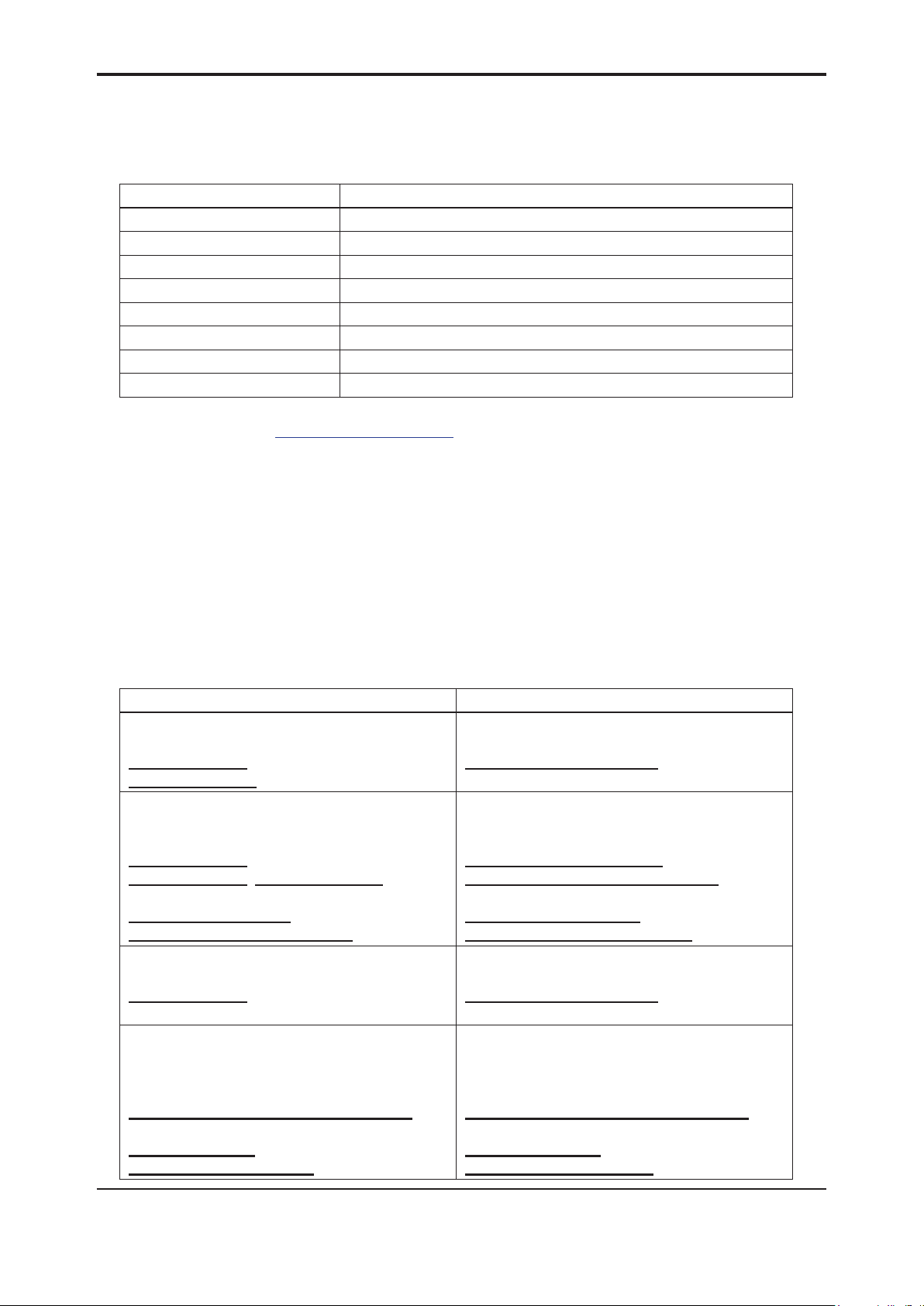
2.1 Information to be added (1)
This manual gives instructions on handling, wiring, installation, maintenance, and general
specications. To ensure correct use, please read this manual and following documents.
Document No. Explanation
IM 01C50B01-01E Hardware (This manual)
IM 01C50T01-01E For HART protocol type
IM 01C50T02-01E For FOUNDATION Fieldbus communication type
IM 01C50T03-01E For BRAIN communication type
GS 01C50B01-00EN YTA110 Temperature Transmitter
GS 01C50B02-00EN YTA310/YTA320 Temperature Transmitter
GS 01C50T01-00EN Model YTA Series HART Communication
GS 01C50T02-00EN Model YTA Series Fieldbus Communication
These documents can be downloaded from the website of Yokogawa.
Website address: http://www.yokogawa.com/d/
2.2 Information to be added (2)
■ForSafeUseofProduct
2
(e) Product Disposal
The instrument should be disposed of in accordance with local and national legislation/regulations.
(f) Authorized Representative in EEA
In relation to the CE Marking, The authorized representative for this product in the EEA (European
Economic Area) is:
Yokogawa Europe B.V.
Euroweg 2, 3825 HD Amersfoort,The Netherlands
2.3 Change applicable standards and Type of Protection and Marking Code
Before Change After Change
ATEX Intrinsically Safe “ia”
Applicable Standard:
EN 60079-0:2012, EN 60079-11:2012,
EN 60079-26:2007
ATEX Flameproof Type and Dust
Ignition Proof Type
Applicable Standard:
EN 60079-0:2012,
EN 60079-1:2007, EN 60079-31:2009
Type of Protection and Marking Code:
II 2 G Ex d IIC T6/T5 Gb,
II 2 D Ex tb IIIC T70°C, T90°C Db
ATEX Intrinsically Safe “ic”
Applicable Standard:
EN 60079-0:2012, EN 60079-11:2012
IECEx Flameproof Type and Dust Ignition
Proof Type
Applicable Standard:
IEC 60079-0:2011,
IEC 60079-1:2007-04, IEC 60079-31:2008
Type of Protection and Marking Code:
Ex d IIC T6/T5 Gb,
Ex tb IIIC T70°C, T90°C Db
ATEX Intrinsically Safe “ia”
Applicable Standard:
EN 60079-0:2012+A11:2013,
EN 60079-11:2012
ATEX Flameproof Type and Dust Ignition
Proof Type
Applicable Standard:
EN 60079-0:2012+A11:2013,
EN 60079-1:2014, EN 60079-31:2014
Type of Protection and Marking Code:
II 2 G Ex db IIC T6/T5 Gb,
II 2 D Ex tb IIIC T70°C / T90°C Db
ATEX Intrinsically Safe “ic”
Applicable Standard:
EN 60079-0:2012+A11:2013,
EN 60079-11:2012
IECEx Flameproof Type and Dust Ignition
Proof Type
Applicable Standard:
IEC 60079-0:2011,
IEC 60079-1:2014-06, IEC 60079-31:2013
Type of Protection and Marking Code:
Ex db IIC T6/T5 Gb,
Ex tb IIIC T70°C / T90°C Db
Manual Change No. 16-007-2
2.4 KS25 pending the sale to EEA market.
Item Description Code
ATEX
ATEX Intrinsically Safe “ia” Approval
Electrical Connection: 1/2 NPT female and M20 female
Note1: Because the examination of conformity to the updated standards is under the way, intrinsically safe type Ex ia
(Option: KS25 for Fieldbus communication type) is pending the sale to EEA market.
KS25
(Note1)
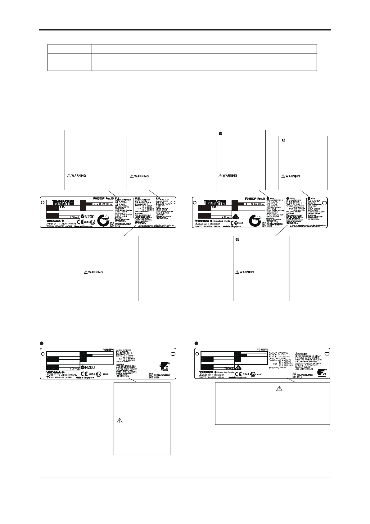
2.5 Change Name Plate.
2.5.1 IM 01C50B01-01E
Before Change After Change
II 1 G
No. KEMA 02ATEX1026 X
Ex ia IIC T5 Ga
Tamb -40 TO 50°C
Ex ia IIC T4 Ga
Tamb -40 TO 70°C
ENCLOSURE: IP66/IP67
SUPPLY INPUT
Ui=30V, Ii=165mA, Pi=900mW
Ci=20nF, Li=730µH
SENSOR OUTPUT
Uo=9V, Io=40mA, Po=90mW
Co=0.7µF, Lo=10mH
POTENTIAL ELECTROSTATIC
CHARGING HAZARD
-SEE USER’S MANUAL
II 3 G
Ex ic IIC T5...T4 Gc
Tamb -30 TO 70°C
(50°C for T5)
ENCLOSURE: IP66/IP67
SUPPLY INPUT
Ui=30V
Ci=28nF, Li=730µH
SENSOR OUTPUT
Uo=9V, Io=40mA, Po=90mW
Co=0.7µF, Lo=10mH
POTENTIAL ELECTROSTATIC
CHARGING HAZARD
-SEE USER’S MANUAL
3
MODEL
SUFFIX
STYLE
SUPPLY
NO.
OUTPUT
CAL
RNG
II 2 GD
No. KEMA 07ATEX0130
Ex d IIC T6/T5 Gb
Ex tb IIIC T70°C, T90°C Db
TEMP. CLASS T6/T5
Tamb(Gas) -40 to +75°C(T6)
-40 to +80°C(T5)
(Dust) -30 to +65°C(T70°C)
-30 to +80°C(T90°C)
ENCLOSURE: IP66/IP67
AFTER DE-ENERGIZING, DELAY
5 MINUTES BEFORE OPENING.
WHEN THE AMBIENT TEMP.≥70°C,
USE THE HEAT-RESISTING
CABLES & CABLE GLANDS≥90°C.
POTENTIAL ELECTROSTATIC
CHARGING HAZARD
-SEE USER’S MANUAL
MODEL
SUFFIX
STYLE
SUPPLY
NO.
OUTPUT
CAL
RNG
II 2 GD
No. KEMA 07ATEX0130
Ex db IIC T6/T5 Gb
Ex tb IIIC T70°C/T90°C Db
TEMP. CLASS T6/T5
Tamb(Gas) -40 to +75°C(T6)
-40 to +80°C(T5)
(Dust) -30 to +65°C(T70°C)
-30 to +80°C(T90°C)
ENCLOSURE: IP66/IP67
AFTER DE-ENERGIZING, DELAY
5 MINUTES BEFORE OPENING.
WHEN THE AMBIENT TEMP.≥70°C,
USE THE HEAT-RESISTING
CABLES & CABLE GLANDS≥90°C.
POTENTIAL ELECTROSTATIC
CHARGING HAZARD
-SEE USER’S MANUAL
2.5.2 IM 01C50T02-01E
Before Change After Change
Name plate for flameproof type Name plate for flameproof type
TEMPERATURE
TRANSMITTER
MODEL
SUFFIX
STYLE
SUPPLY
NO.
YTA
OUTPUT
CAL
RNG
TEMPERATURE
TRANSMITTER
MODEL
SUFFIX
STYLE
SUPPLY
YTA
NO.
OUTPUT
CAL
RNG
No. KEMA 07ATEX0130
Ex d IIC T6/T5 Gb
Ex tb IIIC T70°C, T90°C Db
TEMP. CLASS T6/T5
Tamb (Gas) -40 to +75°C(T6)
-40 to +80°C(T5)
(Dust) -30 to +65°C(T70°C)
-30 to +80°C(T90°C)
ENCLOSURE: IP66/IP67
WARNING
AFTER DE-ENERGIZING. DELAY
5 MINUTES BEFORE OPENING.
WHEN THE AMBIENT TEMP.≥70°C,
USE THE HEAT-RESISTING
CABLES & CABLE GLANDS≥90°C.
POTENTIAL ELECTROSTATIC
CHARGING HAZARD
-SEE USER’ S MANUAL
No. KEMA 07ATEX0130
Ex db IIC T6/T5 Gb
Ex tb IIIC T70°C/T90°C Db
TEMP. CLASS T6/T5
Tamb (Gas) -40 to +75°C(T6)
-40 to +80°C(T5)
(Dust) -30 to +65°C(T70°C)
-30 to +80°C(T90°C)
ENCLOSURE: IP66/IP67
WARNING
AFTER DE-ENERGIZING. DELAY
5 MINUTES BEFORE OPENING.
WHEN THE AMBIENT TEMP.≥70°C,
USE THE HEAT-RESISTING
CABLES & CABLE GLANDS≥90°C.
POTENTIAL ELECTROSTATIC
CHARGING HAZARD
-SEE USER’ S MANUAL
Manual Change No. 16-007-2

u
Y
d
有
型
/
5YTA
变
表
表
共
d
素
所
件
识
该
A
子
の
含
称
件
线
料
质
T
保
品
す
铅(P× × ×
质
害
述
御
汞(Hg
在
量
法
有
)
6
售
期
版
铬
)
气
n
g
苯
下
量
使
6
0
醚
User’
Man
はじめに
本書は
Forewor
This m
产品中
s
al
、中華人民
anual is vali
害物质或元
号
YT
電
和国国内で
only in Chi
的名称及
部件名
Series
情報製
み有効で
na.
量
汚染制
。
b)
管理弁
) 镉(Cd
(中国
Man
害物质
六价
(Cr(VI
版RoHS)
ual Chan
多溴联
)
(PBB)
e No.16-
多溴二苯
(PBDE)
22
YTA110
YTA
温度
○:
×:
环保使用
310/320
0/70
70P
送器
示该部件的
示至少该部
期限:
该标
注)
壳体
基板组
电源连接
有均质材
的某些均
适用于 SJ /
年数为“环
中的有害物
材料中的有
11364 中所
使用期限”
○
○
○
的含量均
害物质的含
,在中华人
,并非产品
○
○
○
GB/T26572
均在 GB/T2
民共和国销
的质量保证
○
○
○
标准中所规
572 标准中
的电子电
。
○
○
○
定的限量以
所规定的限
产品的环保
○
○
○
。
以上。
用期限。
Ju
e 1, 201

User’s
Manual
YTA110, YTA310, YTA320, and YTA710
Temperature Transmitters
Please use this manual change for the manuals listed below.
1. Applicable manuals, revised item, revised contents
Manual Change No. 16-045
DOC No. Edition Page Revised Items
IM 01C50B01-01E 16th 7-1
7-3
7-4
IM 01C50G01-01EN 1st 3-4
7-4
IM 01C50T01-01E 5th 3-5
3-15
IM 01C50T01-02EN 1st 3-11 Figure 3.1 Wire connection and sensor type Delete Ni120.
IM 01C50T02-01E 9th 5-12
5-14
9-3
9-4
IM 01C50T01-02EN 1st 6-2
6-3
6-4
IM 01C50T03-01E 5th 3-4
3-5
3-13
5-1
5-2
Input signal
Table 7.1 Input Type, Measurement Range and Accuracy
Table 7.3 YTA310, YTA320 Effect of Ambient
Temperature
Table 3.4 Parameter List (HART)
Table 7.1 Sensor type, measurement range, and
accuracy
Figure
Table 3.2
SENSOR_TYPE_1(2)
Table 5.16 Recommended Input Levels for Calibration
Table 9.1 Accuracy
Table 9.2 Ambient Temperature Effect
SENSOR_TYPE_1(2)
Figure 6.2 Wire connection and sensor type
Table 6.1 Sensor type and measurement range
Sensor type selection
Figure 3.1 Input terminal wire connection diagram and
sensor type categories
Setting display
Table 3.1 Zero and Gain point value for Sensor trim
5. LIST OF PARAMETERS
SENSOR1 TYPE
5. LIST OF PARAMETERS
SENSOR2 TYPE
Revised
Contents
Delete Ni120.
Delete Ni120.
Delete Ni120.
Delete Ni120.
Delete Ni120.
Delete Ni120.
2. Note
Please do not use Ni120 sensor.
Sep. 14, 2016

User’s
Manual
Please use this manual change with the user’s manuals listed below.
1. Applicable User’s Manual and Page
IM 01C50B01-01E (16th)
Item Page Applicable part and revised contents
CMPL 01C50B01-02E (15th) 2 Change from B1000ER to F9165CS.
YTA Series
Temperature Transmitters
Change from /G11 to /G12.
Delete Table 1-2.
Add *1 in Table 1.
Manual Change No. 17-002
Feb. 10, 2017

Customer
Maintenance
Parts List
2
11
12
YTA Series
Temperature Transmitter
[ Style : S3 ]
13
20
5
7
8
2
1
27
30
31
28
29
3
18
6
4
3
2
1
14
9
10
17
16
15
For FOUNDATION Fieldbus Type
24
12
25
21
19
Yokogawa Electric Corporation
15
23
All Rights Reserved. Copyright © 1998, Yokogawa Electric Corporation
26
6
22
YTA_CMPL.ai
CMPL 01C50B01-02E
15th Edition: Feb. 2017 (YK)

Item Part No. Qty Description
1 F9165EA 2 Cover
2 F9165CS 2 O-Ring
3 Y9406JB 2 Screw Machine
4 See Table 1 1 CPU Assembly for BRAIN or HART Communication type
5 B1002BT 2 Stud Bolt
6 F9342MW 1 Connector Assembly
7 — 1 Name Plate
8 F9300AG 2 Screw
9 F9165DF 1 Tag Plate
10 F9300AG 2 Screw
11 F9165FA 1 Cover Assembly
12 Below 1 LCD Assembly
F9167DB For BRAIN and HART Communication type
F9167DC For Fieldbus Communication type
13 B1001BT 2 Stud Bolt
14 Y9016NU 1 Bolt Hexagon
15 D0117XL-A 1 U-bolt Assembly
16 Y9100SU 1 Washer Spring
17 F9165CY 1 Bracket
18 Y9406ZU 2 Screw (for ATEX, IECEx and TIIS ameproof type)
19 Below 2 Cable Grand Assembly (for TIIS Flameproof; option code: /JF3)
G9601AM For Electrical Connection: G 1/2 female (option code: /G12)
20 — 1 Case Assembly for BRAIN or HART Communication type
21 — 1 Case Assembly for Fieldbus Communication type
22 — 1 CPU Assembly for Fieldbus Communication type
2
23 Y9420JB 2 Screw Machine
24 F9165KA 2 Screw
25 F9165KF 2 Nut
26 F9165KD 2 Stud Bolt
27 F9284NZ 1 Bracket
28 F9165QB 1 Bracket
29 Y9616NU 4 Screw
30 Y9600SU 4 Washer
31 Y9601BU 4 Nut
Table 1. CPU Assembly (for BRAIN and HART)
Model
YTA110
YTA310
YTA320
*1: Applicable for general use. In case of explosion protected type, consult Yokogawa local ofce.
Communication
protocol
-D (BRAIN) F9167BJ —
-E (HART) F9167BM —
-D (BRAIN) F9167BK F9167BU
-E (HART) F9167BN F9167BW
-D (BRAIN) F9167BL F9167BV
-E (HART) F9167BP F9167BX
Without
/CM1
*1
With
/CM1
CPU Assembly is shipped with
the setting shown in Table 2.
Table 2. Setting upon shipment
Input sensor type Pt100 three-wire system
Calibration range lower limit “0”
Calibration range upper limit “100”
Calibration unit “°C”
Sensor burnout High (110%, 21.6 mA DC)
Feb. 2017
Subject to change without notice.
CMPL 01C50B01-02E
 Loading...