

Page 1

User’s
Manual
YTA Series
Temperature T ransmitter
Fieldbus Communication
IM 01C50T02-01E
Yokogawa Electric Corporation
IM 01C50T02-01E
7th Edition
Page 2

CONTENTS
CONTENTS
1. INTRODUCTION............................................................................................ 1-1
Regarding This Manual............................................................................. 1-1
For Safe Use of Product ........................................................................... 1-2
Warranty.................................................................................................... 1-2
ATEX Documentation ............................................................................... 1-3
2. PART NAMES ............................................................................................... 2-1
3. ABOUT FIELDBUS ....................................................................................... 3-1
3.1 Outline ................................................................................................. 3-1
3.2 Internal Structure of YTA .................................................................... 3-1
3.2.1 System/network Management VFD ............................................. 3-1
3.2.2 Function Block VFD ..................................................................... 3-1
3.3 Logical Structure of Each Block.......................................................... 3-1
3.4 Wiring System Configuration .............................................................. 3-2
4. GETTING STARTED .....................................................................................4-1
4.1 Connection of Devices ........................................................................ 4-1
4.2 Host Setting......................................................................................... 4-2
4.3 Bus Power ON .................................................................................... 4-2
4.4 Integration of DD................................................................................. 4-3
4.5 Reading the Parameters ..................................................................... 4-3
4.6 Continuous Record of Values ............................................................. 4-3
4.7 Generation of Alarm............................................................................ 4-3
5. CONFIGURATION.........................................................................................5-1
5.1 Network Design................................................................................... 5-1
5.2 Network Definition ............................................................................... 5-1
5.3 Definition of Combining Function Blocks ............................................ 5-2
5.4 Setting of Tags and Addresses .......................................................... 5-3
5.5 Communication Setting ....................................................................... 5-4
5.5.1 VCR Setting .................................................................................. 5-4
5.5.2 Function Block Execution Control ................................................ 5-5
5.6 Block Setting ....................................................................................... 5-5
5.6.1 Link Object ................................................................................... 5-5
5.6.2 Trend Object ................................................................................. 5-5
5.6.3 View Object .................................................................................. 5-6
5.6.4 Parameters of Transducer Block ............................................... 5-12
5.6.5 Parameters of AI Function Block ............................................... 5-14
5.6.6 Parameters of DI Function Block ............................................... 5-15
5.6.7 A setting when Sensor input 2 is not connected ....................... 5-15
FD No. IM 01C50T02-01E
7th Edition: Nov. 2007(KP)
All Rights Reserved, Copyright © 2000, Yokogawa Electric Corporation
i
IM 01C50T02-01E
Page 3

CONTENTS
6. IN-PROCESS OPERATION .......................................................................... 6-1
6.1 Mode Transition .................................................................................. 6-1
6.2 Generation of Alarm............................................................................ 6-1
6.2.1 Indication of Alarm ....................................................................... 6-1
6.2.2 Alarms and Events ....................................................................... 6-1
6.3 Simulation Function............................................................................. 6-2
6.4 Operation of Integral Indicator ............................................................ 6-2
7. ERRORS AND WARNINGS .......................................................................... 7-1
7.1 Error and Warning Indications ............................................................ 7-1
7.2 Checking with LCD ............................................................................. 7-1
7.3 Checking with DEVICE_STATUS_1 to _8 of Resource Block........... 7-4
7.4 Precautions on Warnings.................................................................... 7-8
8. HANDLING CAUTION ................................................................................... 8-1
8.1 Installation of Explosionproof Type Transmitters................................ 8-1
8.1.1 CSA Certification .......................................................................... 8-1
8.1.2 CENELEC ATEX Certification...................................................... 8-2
8.1.3 FM Certification ........................................................................... 8-6
8.1.4 SAA Certification ......................................................................... 8-9
8.1.5 IECEx Certification ....................................................................... 8-9
9. GENERAL SPECIFICATIONS ...................................................................... 9-1
9.1 Standard Specifications ...................................................................... 9-1
9.2 Optional Specifications........................................................................ 9-2
APPENDIX 1. LIST OF PARAMETERS FOR EACH BLOCK OF THE YTA .. A-1
A1.1 Resource Block ...................................................................................A-1
A1.2 Al Function Block ................................................................................ A-3
A1.3 Dl Function Block ................................................................................A-5
A1.4 Transducer Block ................................................................................ A-6
A1.5 Unit and Code ...................................................................................A-10
APPENDIX 2. Parameters for Basic Settings, and How to Make and Change
the Settings ............................................................................................... A-11
A2.1 Basic Settings and Corresponding Parameters................................A-11
A2.2 Making and Changing Basic Parameter Settings.............................A-12
A2.3 Setting Up the Transducer Block......................................................A-12
A2.4 Setting Up AI Blocks .........................................................................A-15
A2.5 Setting Up DI Blocks.........................................................................A-16
APPENDIX 3. FUNCTION BLOCK DIAGRAM ............................................... A-18
A3.1 AI Block Function Diagram ............................................................... A-18
A3.2 DI Block Function Diagram ...............................................................A-18
ii
IM 01C50T02-01E
Page 4

CONTENTS
APPENDIX 4. PID BLOCK .............................................................................. A-19
A4.1 Function Diagram..............................................................................A-19
A4.2 Functions of PID Block .....................................................................A-19
A4.3 Parameters of PID Block ..................................................................A-20
A4.4 PID Computation Details...................................................................A-22
A4.4.1 PV-proportional and -derivative Type PID (I-PD)
Control Algorithm ........................................................................ A-22
A4.4.2 PID Control Parameters .............................................................A-22
A4.5 Control Output...................................................................................A-22
A4.5.1 Velocity Type Output Action.......................................................A-22
A4.6 Direction of Control Action ................................................................A-22
A4.7 Control Action Bypass.......................................................................A-22
A4.8 Feed-forward .....................................................................................A-22
A4.9 Block Modes......................................................................................A-23
A4.9.1 Mode Transitions.......................................................................A-23
A4.10Bumpless Transfer ............................................................................ A-23
A4.11Setpoint Limiters ...............................................................................A-24
A4.11.1 When PID Block Is in Auto Mode ............................................ A-24
A4.11.2 When PID Block Is in Cas or RCas Mode...............................A-24
A4.12External-output Tracking ................................................................... A-24
A4.13Measured-value Tracking.................................................................. A-24
A4.14Initialization and Manual Fallback (IMan) .........................................A-25
A4.15Manual Fallback ................................................................................ A-25
A4.16Auto Fallback ....................................................................................A-25
A4.17Mode Shedding upon Computer Failure........................................... A-25
A4.17.1 SHED_OPT .............................................................................. A-25
A4.18Alarms ...............................................................................................A-26
A4.18.1 Block Alarm (BLOCK_ALM) .....................................................A-26
A4.18.2 Process Alarms ........................................................................ A-26
A4.19Example of Block Connections ......................................................... A-26
A4.19.1 View Object for PID Function Block.........................................A-27
APPENDIX 5. LINK MASTER FUNCTIONS ................................................... A-29
A5.1 Link Active Scheduler .......................................................................A-29
A5.2 Link Master........................................................................................A-29
A5.3 Transfer of LAS.................................................................................A-30
A5.4 LM Functions.....................................................................................A-31
A5.5 LM Parameters..................................................................................A-32
A5.5.1 LM Parameter List......................................................................A-32
A5.5.2 Descriptions for LM Parameters ................................................A-34
A5.6 FAQs ................................................................................................. A-36
REVISION RECORD
iii
IM 01C50T02-01E
Page 5

Blank Page
Page 6

1. INTRODUCTION
1. INTRODUCTION
This manual contains a description of the YTA320
Temperature Transmitter Fieldbus Communication
Type. The Fieldbus communication type is based on
the same dual sensor input features as that of the
BRAIN or HART communication type and is similar to
the BRAIN or HART communication type in terms of
basic performance and operation. This manual describes only those topics that are required for operation
of the Fieldbus communication type. Refer to the
userⴕs manual “ YTA series Temperature Transmitter
[Hardware]” (IM 01C50B01-01E) for topics common
to other communication types.
Regarding This Manual
•This manual should be passed on to the end user.
• The contents of this manual are subject to change
without prior notice.
• All rights reserved. No part of this manual may be
reproduced in any form without Yokogawa’s written
permission.
• Yokogawa makes no warranty of any kind with
regard to this manual, including, but not limited to,
implied warranty of merchantability and fitness for a
particular purpose.
• If any question arises or errors are found, or if any
information is missing from this manual, please
inform the nearest Yokogawa sales office.
• The specifications covered by this manual are
limited to those for the standard type under the
specified model number break-down and do not
cover custom-made instrument.
• Please note that changes in the specifications,
construction, or component parts of the instrument
may not immediately be reflected in this manual at
the time of change, provided that postponement of
revisions will not cause difficulty to the user from a
functional or performance standpoint.
• The following safety symbol marks are used in this
Manual:
WARNING
Indicates a potentially hazardous situation which,
if not avoided, could result in death or serious
injury.
CAUTION
Indicates a potentially hazardous situation which,
if not avoided, may result in minor or moderate
injury. It may also be used to alert against
unsafe practices.
IMPORTANT
Indicates that operating the hardware or software
in this manner may damage it or lead to system
failure.
NOTE
Draws attention to information essential for
understanding the operation and features.
1-1
IM 01C50T02-01E
Page 7

1. INTRODUCTION
For Safe Use of Product
For the protection and safety of the operator and the
instrument or the system including the instrument,
please be sure to follow the instructions on safety
described in this manual when handling this instrument. In case the instrument is handled in contradiction
to these instructions, Yokogawa does not guarantee
safety. Please give your attention to the followings.
(a) Installation
• The instrument must be installed by an expert
engineer or a skilled personnel. The procedures
described about INSTALLATION are not permitted
for operators.
• In case of high process temperature, care should be
taken not to burn yourself because the surface of the
case reaches a high temperature.
• All installation shall comply with local installation
requirement and local electrical code.
(b) Wiring
• The instrument must be installed by an expert
engineer or a skilled personnel. The procedures
described about WIRING are not permitted for
operators.
• Please confirm that voltages between the power
supply and the instrument before connecting the
power cables and that the cables are not powered
before connecting.
(c) Maintenance
• Please do not carry out except being written to a
maintenance descriptions. When these procedures
are needed, please contact nearest YOKOGAWA
office.
•Care should be taken to prevent the build up of drift,
dust or other material on the display glass and
name plate. In case of its maintenance, soft and dry
cloth is used.
Warranty
•The warranty shall cover the period noted on the
quotation presented to the purchaser at the time of
purchase. Problems occurred during the warranty
period shall basically be repaired free of charge.
• In case of problems, the customer should contact the
Yokogawa representative from which the instrument
was purchased, or the nearest Yokogawa office.
• If a problem arises with this instrument, please
inform us of the nature of the problem and the
circumstances under which it developed, including
the model specification and serial number. Any
diagrams, data and other information you can
include in your communication will also be helpful.
• Responsible party for repair cost for the problems
shall be determined by Yokogawa based on our
investigation.
• The Purchaser shall bear the responsibility for repair
costs, even during the warranty period, if the
malfunction is due to:
- Improper and/or inadequate maintenance by the
purchaser.
- Failure or damage due to improper handling, use
or storage which is out of design conditions.
- Use of the product in question in a location not
conforming to the standards specified by
Yokogawa, or due to improper maintenance of
the installation location.
- Failure or damage due to modification or repair
by any party except Yokogawa or an approved
representative of Yokogawa.
- Malfunction or damage from improper relocation
of the product in question after delivery.
- Reason of force majeure such as fires, earthquakes, storms/floods, thunder/lightening, or
other natural disasters, or disturbances, riots,
warfare, or radioactive contamination.
(d) Modification
• Yokogawa will not be liable for malfunctions or
damage resulting from any modification made to
this instrument by the customer.
1-2
IM 01C50T02-01E
Page 8

1. INTRODUCTION
ATEX Documentation
This procedure is only applicable to the countries in
European Union.
GB
All instruction manuals for ATEX Ex related products
are available in English, German and French. Should
you require Ex related instructions in your local
language, you are to contact your nearest Yokogawa
office or representative.
DK
Alle brugervejledninger for produkter relateret til
ATEX Ex er tilgængelige på engelsk, tysk og fransk.
Skulle De ønske yderligere oplysninger om håndtering
af Ex produkter på eget sprog, kan De rette
henvendelse herom til den nærmeste Yokogawa
afdeling eller forhandler.
I
Tutti i manuali operativi di prodotti ATEX
contrassegnati con Ex sono disponibili in inglese,
tedesco e francese. Se si desidera ricevere i manuali
operativi di prodotti Ex in lingua locale, mettersi in
contatto con l’ufficio Yokogawa più vicino o con un
rappresentante.
E
Todos los manuales de instrucciones para los productos
antiexplosivos de ATEX están disponibles en inglés,
alemán y francés. Si desea solicitar las instrucciones de
estos artículos antiexplosivos en su idioma local,
deberá ponerse en contacto con la oficina o el
representante de Yokogawa más cercano.
NL
SF
Kaikkien ATEX Ex -tyyppisten tuotteiden käyttöhjeet
ovat saatavilla englannin-, saksan- ja ranskankielisinä.
Mikäli tarvitsette Ex -tyyppisten tuotteiden ohjeita
omalla paikallisella kielellännne, ottakaa yhteyttä
lähimpään Yokogawa-toimistoon tai -edustajaan.
P
Todos os manuais de instruções referentes aos produtos
Ex da ATEX estão disponíveis em Inglês, Alemão e
Francês. Se necessitar de instruções na sua língua
relacionadas com produtos Ex, deverá entrar em
contacto com a delegação mais próxima ou com um
representante da Yokogawa.
F
Tous les manuels d’instruction des produits ATEX Ex
sont disponibles en langue anglaise, allemande et
française. Si vous nécessitez des instructions relatives
aux produits Ex dans votre langue, veuillez bien
contacter votre représentant Yokogawa le plus proche.
D
Alle Betriebsanleitungen für ATEX Ex bezogene
Produkte stehen in den Sprachen Englisch, Deutsch
und Französisch zur Verfügung. Sollten Sie die
Betriebsanleitungen für Ex-Produkte in Ihrer
Landessprache benötigen, setzen Sie sich bitte mit
Ihrem örtlichen Yokogawa-Vertreter in Verbindung.
S
Alla instruktionsböcker för ATEX Ex (explosionssäkra)
produkter är tillgängliga på engelska, tyska och
franska. Om Ni behöver instruktioner för dessa
explosionssäkra produkter på annat språk, skall Ni
kontakta närmaste Yokogawakontor eller representant.
Alle handleidingen voor producten die te maken
hebben met ATEX explosiebeveiliging (Ex) zijn
verkrijgbaar in het Engels, Duits en Frans. Neem,
indien u aanwijzingen op het gebied van
explosiebeveiliging nodig hebt in uw eigen taal, contact
op met de dichtstbijzijnde vestiging van Yokogawa of
met een vertegenwoordiger.
GR
ATEX Ex
, .
Ex
Yokogawa .
1-3
IM 01C50T02-01E
Page 9
1. INTRODUCTION
SK
CZ
LT
PL
SLO
H
LV
EST
BG
RO
M
1-4
IM 01C50T02-01E
Page 10
2. PART NAMES
Refer to the individual instruction manuals for detailed
descriptions of the parts. This section describes the
topics applicable to the Fieldbus communication type.
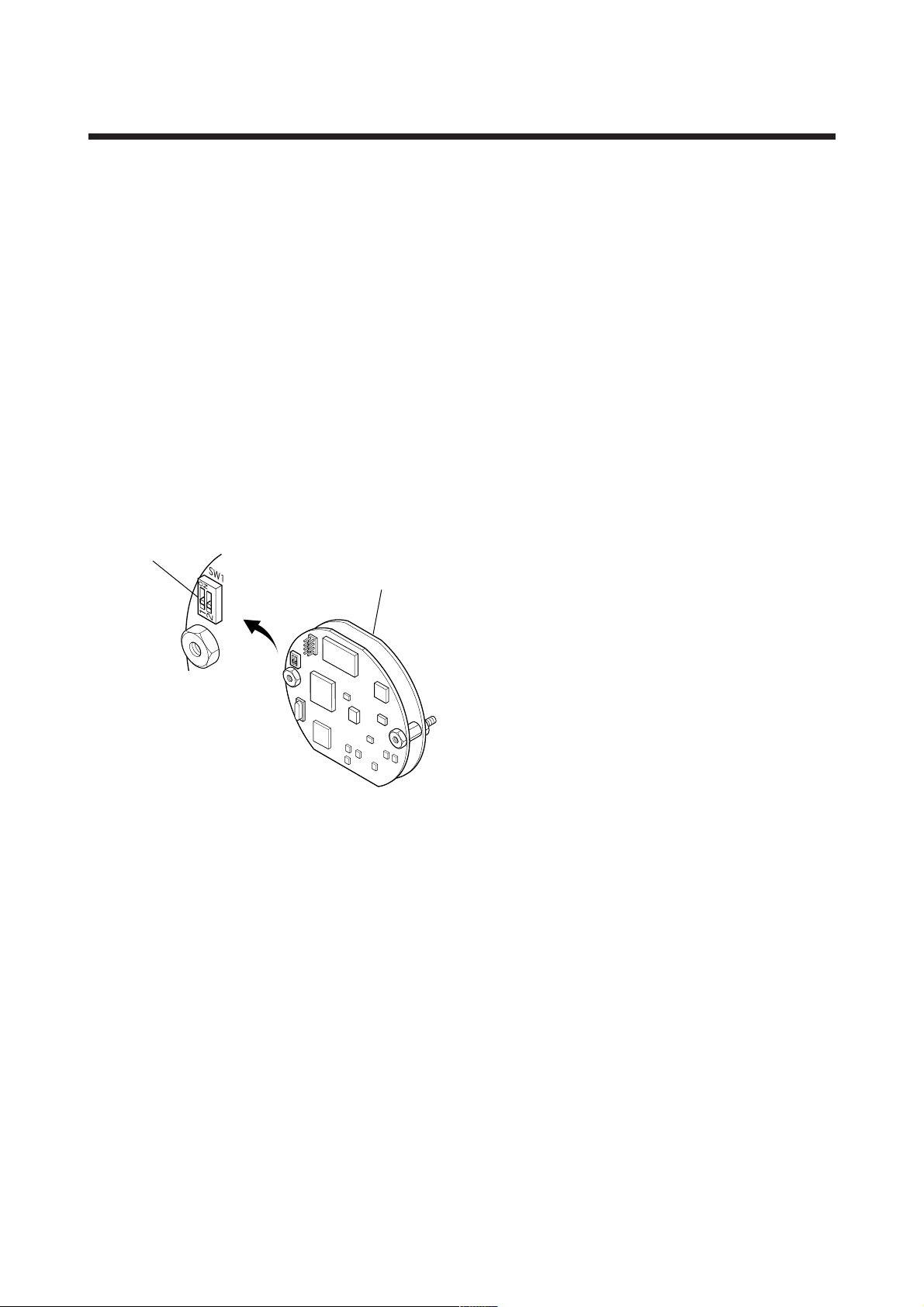
(1) In the Fieldbus communication type, the
amplifier(CPU) assembly consists of two boards,
as shown in Figure 2.1.
(2) In other communication types, there's the pin
switch which is used for selecting the direction of
hardware burnout at the position of 'SW1' on the
amplifier assembly, while Fieldbus communication
type does not have this pin.
(3) The Fieldbus communication type has a simulation
function. A SIMULATE-ENABLE switch is
mounted at 'SW1' on the amplifier. Refer to
Section 6.3, “Simulation Function” for details of
the simulation function.
2. PART NAMES
Simulation
setting switch
Amplifier Assembly
Figure 2.1 Diagram of the Amplifier Assembly
F0201.EPS
2-1
IM 01C50T02-01E
Page 11
3. ABOUT FIELDBUS
3. ABOUT FIELDBUS
3.1 Outline
Fieldbus is a bi-directional digital communication
protocol for field devices, which offers an advancement in
implementation technologies for process control systems
and is widely employed by numerous field devices.
YTA Series Fieldbus communication type employs the
specification standardized by The Fieldbus Foundation,
and provides interoperability between Yokogawa
devices and those produced by other manufacturers.
Fieldbus comes with software consisting of four AI
function blocks and four DI function blocks, providing
the means to implement a flexible instrumentation
system.
For information on other features, engineering, design,
construction work, startup and maintenance of
Fieldbus, refer to “Fieldbus Technical Information” (TI
38K3A01-01E).
3.2 Internal Structure of YTA
The YTA contains two virtual field devices (VFD) that
share the following functions.
• Outputs temperature signal.
•Carries out scaling, damping and square root
extraction.
(4)DI function block
•Limit switch for temperature.
•Accepts the discrete signal from Transducer block
and Outputs the discrete signal to show if the
temperature exceeds the preset limit.
(5)PID function block
• Performs the PID control computation based on the
deviation of the measured value from the setpoint.
3.3 Logical Structure of Each
Block
YTA
Fieldbus
System/network management VFD
PD Tag
Node address
Link Master (option)
Communication
parameters
VCR
Function block
execution schedule
3.2.1 System/network Management VFD
• Sets node addresses and Phisical Device tags (PD
Tag) necessary for communication.
• Controls the execution of function blocks.
•Manages operation parameters and communication
resources (Virtual Communication Relationship:
VCR).
3.2.2 Function Block VFD
(1)Resource block (RS)
• Manages the status of YTA hardware.
•Automatically informs the host of any detected
faults or other problems.
(2)Transducer block (TR)
• Accepts temperature input from sensors and transfers to AI function block.
• Operates limit swtich calculation and transfers to DI
function block.
(3)AI function block
• Conditions raw data from the Transducer block.
Function block VFD
PID function
block (option)
DI function
Transducer
Sensor
input
Sensor
block
Block tag
Parameters
Temperature
Resource block
Block tag
Parameters
Figure 3.1 Logical Structure of Each Block
block
AI function
block
Block tag
Parameters
OUT
Setting of various parameters, node addresses, and PD
Tags shown in Figure 3.1 is required before starting
operation.
Output
F0301.EPS
3-1
IM 01C50T02-01E
Page 12

3.4 Wiring System Configuration
The number of devices that can be connected to a
single bus and the cable length vary depending on
system design. When constructing systems, both the
basic and overall design must be carefully considered
to allow device performance to be fully exhibited.
3. ABOUT FIELDBUS
3-2
IM 01C50T02-01E
Page 13

4. GETTING STARTED
4. GETTING STARTED
Fieldbus is fully dependent upon digital communication protocol and differs in operation from conventional 4 to 20 mA transmission and the BRAIN or
HART communication protocol. It is recommended
that novice users use field devices in accordance with
the procedures described in this section. The procedures assume that field devices will be set up on a
bench or an instrument shop.
4.1 Connection of Devices
The following instruments are required for use with
Fieldbus devices:
• Power supply:
Fieldbus requires a dedicated power supply. It is
recommended that current capacity be well over the
total value of the maximum current consumed by all
devices (including the host). Conventional DC
current cannot be used as is.
• Terminator:
Fieldbus requires two terminators. Refer to the
supplier for details of terminators that are attached
to the host.
•Field devices:
Connect Fieldbus communication type YTA320.
Two or more YTA320 devices or other devices can
be connected.
• Host:
Used for accessing field devices. A dedicated host
(such as DCS) is used for an instrumentation line
while dedicated communication tools are used for
experimental purposes. For operation of the host,
refer to the instruction manual for each host. No
details of the host are explained in the rest of this
material.
processing depends on the type of device being
deployed. For YTA, use an M4 screw terminal claw.
Some hosts require a connector.
Refer to Yokogawa when making arrangements to
purchase the recommended equipment.
Connect the devices as shown in Figure 4.1. Connect
the terminators at both ends of the trunk, with a
minimum length of the spur laid for connection.
The polarity of signal and power must be maintained.
Fieldbus power
supply
Terminator
Figure 4.1 Cabling
YTA320
HOST
Terminator
F0401.EPS
NOTE
No CHECK terminal is used for Fieldbus communication YTA. Do not connect the field indicator and check meter. Use the instrument with the
short-bar being installed between (-) terminal
and the CHECK terminal.
Before using a Fieldbus configuration tool other than
the existing host, confirm it does not affect the loop
functionality in which all devices are already installed
in operation. Disconnect the relevant control loop from
the bus if necessary.
•Cable:
Used for connecting devices. Refer to “Fieldbus
Technical Information” (TI 38K3A01-01E) for
details of instrumentation cabling. If the total length
of the cable is in a range of 2 to 3 meters for
laboratory or other experimental use, the following
simplified cable (a twisted pair wire with a cross
section of 0.9 mm2 or more and cycle period of
within 5 cm (2 inches) may be used. Termination
IMPORTANT
Connecting a Fieldbus configuration tool to a
loop with its existing host may cause communication data scrambles resulting in a functional
disorder or a system failure.
4-1
IM 01C50T02-01E
Page 14

4. GETTING STARTED
4.2 Host Setting
To activate Fieldbus, the following settings are
required for the host.
IMPORTANT
Do not turn off the power immediately after
setting. When the parameters are saved to
EEPROM, the redundant processing is executed
for the improvement of reliability. If the power is
turned off within 60 seconds after setting is
made, the modified parameters are not saved
and the settings may return to the original
values.
Table 4.1 Operation Parameters
Symbol Parameter Description and Settings
V (ST) Slot-Time
V (MID)
Minimum-Inter-PDUDelay
V (MRD)
Maximum-ResponseDelay
V (FUN) First-Unpolled-Node
V (NUN) Number-of-
consecutiveUnpolled-Node
0x00
Set 4 or greater value.
Set 4 or greater value.
Set so that V (MRD) V
(ST) is 12 or greater
Indicate the address next
to the address range used
by the host. Set 0x15 or
greater.
Unused address range.
YTA address is factory-set
to 0xF3. Set this address to
be within the range of the
BASIC device in Figure
4.2.
T0401.EPS
Not used
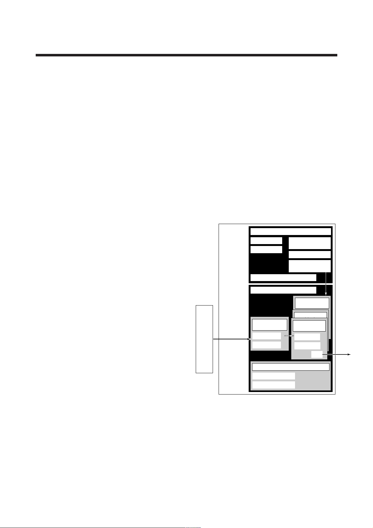
4.3 Bus Power ON
Turn on the power of the host and the bus. Where the
YTA is equipped with an LCD indicator, first all
segments are lit, then the display begins to operate. If
the indicator is not lit, check the polarity of the power
supply.
Using the host device display function, check that the
YTA is in operation on the bus.
The device information, including PD tag, Node
address, and Device ID, is described on the sheet
attached to YTA. The duplicates of device information
are provided on this sheet.
Device ID : 5945430005XXXXXXXX
PD Tag : TT1001
Device Revision : 2
Node Address : 0xf3
Serial No. : XXXXXXXXXXXXXXXXX
Physical Location :
Note:
Our Device Description Files and Capabilities Files available at
http://www.yokogawa.com/fld (English) or
http://www.yokogawa.co.jp/Sensor/fieldbus/download.htm (Japanese)
DEVICE INFORMATION
DEVICE INFORMATION
0x10
Bridge device
0x14
LM device
V(FUN)
Unused V(NUN)
V(FUN)V(NUN)
YTA(0xF3)
0xF7
0xF8
BASIC device
Default address
0xFB
0xFC
Portable device address
0xFF
Note 1: LM device: with bus control function (Link Master function)
Note 2: BASIC device: without bus control function
F0402.EPS
Figure 4.2 Available Address Range
Figure 4.3 Device Information Sheet Attached to YTA
If no YTA is detected, check the available address
range and the polarity of the power supply. If the node
address and PD tag are not specified when ordering,
default value is factory set. If two or more YTAs are
connected at a time with default value, one YTA will
keep the address upon shipment while the other will
have a default address as they have the same initial
addres. Separately connect each YTA and set a
different address for each.
4-2
IM 01C50T02-01E
F0403.EPS
Page 15

4. GETTING STARTED
4.4 Integration of DD
If the host supports DD (Device Description), the DD
of the YTA needs to be installed. Check if host has the
following directory under its default DD directory.
594543\0005
(594543 is the manufacturer number of Yokogawa
Electric Corporation, and 0005 is the YTA device
number, respectively.)
If this directory is not found, DD of YTA has not been
included. Create the above directory and copy the DD
file (0m0n.ffo,0m0n.sym) (m, n is a numeral) into the
directory. If you do not have the DD or capabilities
files, you can download them from our web site. Visit
the following web site.
http://www.yokogawa.com/fld
Once the DD is installed in the directory, the name and
attribute of all parameters of the YTA are displayed.
Off-line configuration is possible by using capabilities
files.
NOTE
Ensure to use the suitable file for the device.
YTA has three types, one with the standard
function blocks, one with /LC1(additional PID
and LAS function) and one with /LC2(additional
2 PIDs and LAS function). If the different type
capabilities file is used, some errors may occur
at downloading to the device.
4.6 Continuous Record of Values
If the host has a function of continuously recording the
indications, use this function to list the indications
(values). Depending on the host being used, it may be
necessary to set the schedule of Publish (the function
that transmits the indication on a periodic basis).
4.7 Generation of Alarm
If the host is allowed to receive alarms, generation of
an alarm can be attempted from YTA. In this case, set
the reception of alarms on the host side. YTA’s VCR-6
is factory-set for this purpose. For practical purposes,
all alarms are placed in a disabled status; for this
reason, it is recommended that you first use one of
these alarms on a trial basis. Set the value of link
object-3 (index 30002) as “0, 298, 0, 6, 0”. Refer to
section 5.6.1 Link Object for details.
Since the LO_PRI parameter (index 4029) of the AI1
block is set to “0”, try setting this value to “3”. Select
the Write function from the host in operation, specify
an index or variable name, and write “3” to it.
The LO_LIM parameter (index 4030) of the AI1 block
determines the limit at which the lower bound alarm
for the process value is given. In usual cases, a very
small value is set to this limit. Set the value which is
apparantely higher than expected measured value to the
limit. For example, in case masuering room temperature of 28C, SET '50(C)' to the limit. Since the
measured temperature is lower than the limit, lower
bound alarm is raised. Check that the alarm can be
received at the host. When the alarm is confirmed,
transmission of the alarm is suspended.
4.5 Reading the Parameters
To read YTA parameters, select the AI1 block of the
YTA from the host screen and read the OUT parameter. The current temperature which is assign to AI1
block is displayed. Sensor 1 input is assigned to AI1
block upon shipment. Check that actual of
MODE_BLOCK of the function block and resource
block is set to Auto, and increase the temperature
measured by Sensor1 and read the parameter again. A
new designated value should be displayed.
The above-mentioned items are a description of the
simple procedure to be carried out until YTA is
connected to Fieldbus. In order to take full advantage
of the performance and functionality of the device, it is
recommended that it be read together with Chapter 5,
which describes how to use the YTA.
4-3
IM 01C50T02-01E
Page 16

5. CONFIGURATION
5. CONFIGURATION
This chapter contains information on how to adapt the
function and performance of the YTA to suit specific
applications. Because two or more devices are connected to Fieldbus, settings including the requirements
of all devices need to be determined. Practically, the
following steps must be taken.
(1)Network design
Determines the devices to be connected to Fieldbus
and checks the capacity of the power supply.
(2)Network definition
Determines the tag and node addresses for all
devices.
(3)Definition of combining function blocks
Determines the method for combination between
each function block.
(4)Setting tags and addresses
Sets the PD Tag and node addresses one by one for
each device.
(5)Communication setting
Sets the link between communication parameters
and function blocks.
(6)Block setting
Sets the parameters for function blocks.
The following section describes each step of the
procedure in the order given. Using a dedicated
configuration tool allows the procedure to be significantly simplified. This section describes the procedure
to be assigned for a host which has relatively simple
functions. Refer to Appendix 5 when the YTA is used
as Link Master.
• Terminator
Fieldbus requires two terminators. Refer to the
supplier for details of terminators that are attached
to the host.
•Field devices
Connect the field devices necessary for instrumentation. YTA has passed the interoperability test
conducted by The Fieldbus Foundation. In order to
properly start Fieldbus, it is recommended that the
devices used satisfy the requirements of the above
test.
• Host
Used for accessing field devices. A minimum of one
device with bus control function is needed.
• Cable
Used for connecting devices. Refer to “Fieldbus
Technical Information” for details of instrumentation cabling. Provide a cable sufficiently long to
connect all devices. For field branch cabling, use
terminal boards or a connection box as required.
First, check the capacity of the power supply. The
power supply capacity must be greater than the sum of
the maximum current consumed by all devices to be
connected to Fieldbus. The maximum current consumed (power supply voltage 9 V to 32 V) for YTA is
16.6 mA. The cable must have the spur in a minimum
length with terminators installed at both ends of the
trunk.
5.2 Network Definition
5.1 Network Design
Select the devices to be connected to the Fieldbus
network. The following instruments are necessary for
operation of Fieldbus.
• Power supply
Fieldbus requires a dedicated power supply. It is
recommended that current capacity be well over the
total value of the maximum current consumed by all
devices (including the host). Conventional DC
current cannot be used as is.
Before connection of devices with Fieldbus, define the
Fieldbus network. Allocate PD Tag and node addresses
to all devices (excluding such passive devices as
terminators).
The PD Tag is the same as the conventional one used
for the device. Up to 32 alphanumeric characters may
be used for definition. Use a hyphen as a delimiter as
required.
The node address is used to specify devices for
communication purposes. Because data is too long for
a PD Tag, the host uses the node address in place of
the PD Tag for communication. A range of 16 to 247
5-1
IM 01C50T02-01E
Page 17

5. CONFIGURATION
(or hexadecimal 10 to F7) can be set. The device (LM
device) with bus control function (Link Master
function) is allocated from a smaller address number
(16) side, and other devices (BASIC device) without
bus control function allocated from a larger address
number (247) side respectively. Place YTA in the
range of the BASIC device. When the YTA is used as
Link Master, place YTA in the range of LM device.
Set the range of addresses to be used to the LM device.
Set the following parameters.
Table 5.1 Parameters for Setting Address Range
Symbol
V (FUN) First-Unpolled-Node
V (NUN) Number-of-
Parameters Description
Indicates the address next
to the address range used
for the host or other LM
device.
Unused address range
consecutiveUnpolled-Node
T0501.EPS
The devices within the address range written as
“Unused” in Figure 5.1 cannot be used on a Fieldbus.
For other address ranges, the range is periodically
checked to identify when a new device is mounted.
Care must be taken not to allow the address range to
become wider, which can lead to exhaustive consumption of Fieldbus communication performance.
0x00
Not used
0x10
Bridge device
0x14
V(FUN)
V(FUN)V(NUN)
0xF7
0xF8
0xFB
0xFC
0xFF
Figure 5.1 Available Range of Node Addresses
LM device
Unused V(NUN)
BASIC device
Default address
Portable device address
F0501.EPS
To ensure stable operation of Fieldbus, determine the
operation parameters and set them to the LM devices.
While the parameters in Table 5.2 are to be set, the
worst-case value of all the devices to be connected to
the same Fieldbus must be used. Refer to the specification of each device for details. Table 5.2 lists YTA
specification values.
Table 5.2 Operation Parameter Values of the YTA to be
Set to LM Devices
Symbol Parameters Description and Settings
V (ST) Slot-Time
V (MID) Minimum-Inter-PDU-
Delay
V (MRD) Maximum-Reply-Delay
Indicates the time
necessary for immediate
reply of thje device. Unit of
time is in octets (256 µs).
Set maximum specification
for all devices. For YTA,
set a value of 4 or greater.
Minimum value of
communication data
intervals. Unit of time is in
octets (256 µs). Set the
maximum specification for
all devices. For YTA, set a
value of 4 or greater.
The worst case time
elapsed until a reply is
recorded. The unit is Slottime; set the value so that
V (MRD) V (ST) is the
maximum value of the
specification for all
devices. For YTA, the
setting must be a value of
12 or greater.
5.3 Definition of Combining Function Blocks
The input/output parameters for function blocks are
combined. For the YTA, four AI blocks output
parameter (OUT), four DI blocks output parameter
(OUT_D) and PID block are subject to combination.
They are combined with the input of the control block
as necessary. Practically, setting is written to the YTA
link object with reference to “Block setting” in Section
5.6 for details. It is also possible to read values from
the host at proper intervals instead of connecting the
YTA block output to other blocks.
The combined blocks need to be executed synchronously with other blocks on the communications
schedule. In this case, change the YTA schedule
according to the following table. Enclosed values in the
table are factory-settings.
Table 5.3 Execution Schedule of the YTA Function Blocks
Setting (Enclosed is
factory-setting)
Cycle (MACROCYCLE)
period of control or
measurement. Unit is 1/32
ms. (16000 = 0.5 s)
AI1 block startup time.
Elapsed time from the start
of MACROCYCLE specified
in 1/32 ms. (0 = 0 s)
AI2 block startup time.
Elapsed time from the start
of MACROCYCLE specified
in 1/32 ms. (4000 = 125ms)
Not used.
IM 01C50T02-01E
5-2
Index Parameters
269
MACROCYCLE_
(SM)
DURATION
276
FB_START_ENTRY.1
(SM)
277
FB_START_ENTRY.2
(SM)
278
FB_START_ENTRY.3
to
to
FB_START_ENTRY.10
285
(SM)
T0502.EPS
T0503.EPS
Page 18

5. CONFIGURATION
A maximum of 50 ms is taken for execution of each
AI block. A maximum of 30 ms is taken for execution
of each DI block, and 100ms for each PID block. For
scheduling of communications for combination with
the next function block, the execution is so arranged as
to start after a lapse of longer than 100 ms. In no case
should function blocks of the YTA be executed at the
same time (execution time is overlapped).
Figure 5.3 shows an example of schedule based on the
loop shown in Figure 5.2.
TIC100
YTA
#1
TT100
YTA
#2
TT 200
Figure 5.2 Example of Loop Connecting Function Block of
Two YTA with Other Instruments
TC200
TV200
F0502.EPS
5.4 Setting of Tags and Addresses
This section describes the steps in the procedure to set
PD Tags and node addresses in the YTA. There are
three states of Fieldbus devices as shown in Figure 5.4,
and if the state is other than the lowest
SM_OPERATIONAL state, no function block is
executed. YTA must be transferred to this state when
an YTA tag or address is changed.
UNINITIALIZED
(No tag nor address is set)
Tag clear Tag setting
INITIALIZED
(Only tag is set)
Address clear
SM_OPERATIONAL
(Tag and address are retained, and
the function block can be executed.)
Figure 5.4 Status Transition by Setting PD Tag and Node
Address
Address setting
F0504.EPS
Macrocycle (Control Period)
TT100
OUT
Function
Block
Schedule
Commu-
nication
Schedule
Figure 5.3 Function Block Schedule and Communication
Schedule
IN
TIC100
BKCAL_IN
TT200
OUT
CAS_IN
TC200
IN
BKCAL_IN
Unscheduled
Communication
BKCAL_OUT
TV200
BKCAL_OUT
Scheduled
Communication
F0503.EPS
When the control period (macrocycle) is set to more
than 4 seconds, set the following interval to be more
than 1% of the control period.
- Interval between “end of block execution” and “start
of sending CD from LAS”
- Interval between “end of block execution” and “start
of the next block execution”
YTA has a PD Tag (TT1001) and node address (243,
or hexadecimal 0xF3) that are set upon shipment from
the factory unless otherwise specified. To change only
the node address, clear the address once and then set a
new node address. To set the PD Tag, first clear the
node address and clear the PD Tag, then set the PD
Tag and node address again.
Devices whose node address was cleared will await the
default address (randomly chosen from a range of 248
to 251, or from hexadecimal F8 to FB). At the same
time, it is necessary to specify the device ID in order to
correctly specify the device. The device ID of the YTA
is 5945430005xxxxxxxx. (The xxxxxxxx at the end of
the above device ID is a total of 8 alphanumeric
characters.)
5-3
IM 01C50T02-01E
Page 19

5. CONFIGURATION
5.5 Communication Setting
To set the communication function, it is necessary to
change the database residing in SM-VFD.
5.5.1 VCR Setting
Set VCR (Virtual Communication Relationship), which
specifies the called party for communication and
resources. YTA has 30 VCRs whose application can be
changed, except for the first VCR, which is used for
management.
YTA has VCRs of four types:
Server(QUB) VCR
A Server responds to requests from a host. This
communication needs data exchange. This type of
communication is called QUB (Queued Usertriggered Bidirectional) VCR.
Source (QUU) VCR
A Source multicasts alarms or trends to other
devices. This type of communication is called QUU
(Queued User-triggered Unidirectional) VCR.
Publisher (BNU) VCR
A Publisher multicasts AI block and DI block output
to another function block(s). This type of communication is called BNU (Buffered Network-triggered
Unidirectional) VCR.
Subscriber (BNU) VCR
A Subscriber receives output of another function
block(s) by PID block.
A Server VCR is capable to respond to requests from a
Client (QUB) VCR after the Client initiates connection
to the Server successfully. A Source VCR transmits
data without established connection. A Sink (QUU)
VCR on another device can receive it if the Sink is
configured so. A Publisher VCR transmits data when
LAS requests so. An explicit connection is established
from Subscriber (BNU) VCR(s) so that a Subscriber
knows the format of published data.
Each VCR has the parameters listed in Table 5.4.
Parameters must be changed together for each VCR
because modification for each parameter may cause
inconsistent operation.
Table 5.4 VCR Static Entry
Sub-
index
1 FasArTypeAndRole
2 FasDllLocalAddr
3 FasDllConfigured
4 FasDllSDAP
5 FasDllMaxConfirm
6 FasDllMaxConfirm
7 FasDllMaxDlsduSize
8 FasDllResidual
9 FasDllTimelinessClass
10 FasDllPublisherTime
11 FasDllPublisher
Parameter Description
RemoteAddr
DelayOnConnect
DelayOnData
ActivitySupported
WindowSize
SynchronizaingDlcep
Indicates the type and role of
communication (VCR). The
following 4 types are used
for YTA.
0x32: Server (Responds to
requests from host.)
0x44: Source (Transmits
alarm or trend.)
0x66: Publisher (Sends AI
block output to other
blocks.)
0x76: Subscriber (Receives
output of other blocks
by PID block.)
Sets the local address to
specify VCR in YTA. A range
of 20 to F7 in hexadecimal.
Sets the node address of the
called party for
communication and the
address (DLSAP or DLCEP)
used to specify VCR in that
address. For DLSAP or
DLCEP, a range of 20 to F7
in hexadecimal is used.
Addresses in Subindex 2
and 3 need to be set to the
same contents of the VCR
as the called party (local and
remote are reversed).
Specifies the quality of
communication. Usually, one
of the following types is set.
0x2B: Server
0x01: Source (Alert)
0x03: Source (Trend)
0x91: Publisher/Subscriber
To establish connection for
communication, a maximum
wait time for the called
party's response is set in
ms. Typical value is 60
seconds (60000).
For request of data, a
maximum wait time for the
called party's response is
set in ms. Typical value is
60 seconds (60000).
Specifies maximum DL
Service Data unit Size
(DLSDU). Set 256 for Server
and Trend VCR, and 64 for
other VCRs.
Specifies whether
connection is monitored. Set
TRUE (0xff) for Server. This
parameter is not used for
other communication.
Not used for YTA.
Not used for YTA.
Not used for YTA.
T0504-1.EPS
5-4
IM 01C50T02-01E
Page 20

5. CONFIGURATION
Sub-
index
12 FasDllSubsriberTime
13 FasDllSubscriber
14 FmsVfdId
15 FmsMaxOutstanding
16 FmsMaxOutstanding
17 FmsFeatures
Parameter
WindowSize
SynchronizationDlcep
ServiceCalling
ServiceCalled
Supported
Description
Not used for YTA.
Not used for YTA.
Sets VFD for YTA to be
used.
0x1: System/network
management VFD
0x1234: Function block
VFD
Set 0 to Server. It is not
used for other applications.
Set 1 to Server. It is not
used for other applications.
Indicates the type of
services in the application
layer. In the YTA, it is
automatically set according
to specific applications.
T0504-2.EPS
30 VCRs are factory-set as shown in the table below.
Table 5.5 VCR List
Index
(SM)
293 For system management (Fixed)1
294 Server (LocalAddr = 0xF3)2
295 Server (LocalAddr = 0xF4)3
296 Server (LocalAddr = 0xF7)4
297 Trend Source (LocalAddr = 0x07,
298 6
299
322
VCR
Number
5
Remote Address=0x111)
Alert Source (LocalAddr = 0x07,
Remote Address=0x110)
7 to 30
to
Not used.
Factory Setting
T0505.EPS
5.5.2 Function Block Execution Control
According to the instructions given in Section 5.3, set
the execution cycle of the function blocks and schedule
of execution.
Parameters must be changed together for each VCR
because the modifications made to each parameter may
cause inconsistent operation.
Table 5.6 Link Object Parameters
Sub-
index
1 LocalIndex
2 VcrNumber
3 RemoteIndex
4 ServiceOperation
5StaleCountLimit
Parameters Description
Sets the index of function
block parameters to be
combined; set “0” for Trend
and Alert.
Sets the index of VCR to
be combined. If set to “0”,
this link object is not used.
Not used in YTA.Set to “0”.
Set one of the following.
Set only one each for link
object for Alert or Trend.
0: Undefined
2: Publisher
3: Subscriber
6: Alert
7: Trend
Set the maximum number
of consecutive stale input
values which may be
received before the input
status is set to BAD. To
avoid the unnecessary
mode transition caused
when the data is not
correctly received by
subscriber, set this
parameter to “2” or more.
T0506.EPS
26 Link objects are not factory-set.
5.6.2 Trend Object
It is possible to set the parameter so that the function
block automatically transmits Trend. YTA has ten
Trend objects, six of which are used for Trend in
analog mode parameters and four is used for Trend in
discrete mode parameter. A single Trend object
specifies the trend of one parameter.
Each Trend object has the parameters listed in Table
5.8. The first four parameters are the items to be set.
5.6 Block Setting
Set the parameter for function block VFD.
5.6.1 Link Object
Link object combines the data voluntarily sent by the
function block with VCR. YTA has 26 link objects. A
single link object specifies one combination. Each link
object has the parameters listed in Table 5.6.
5-5
IM 01C50T02-01E
Page 21

5. CONFIGURATION
Table 5.8 Parameters for Trend Objects
Sub-
index
1 Block Index
2 Parameter Relative
3 Sample Type
4 Sample Interval
5 Last Update
6 to 21 List of Status
21 to 37 List of Samples
Parameters
Index
Description
Sets the leading index of
the function block that
takes a trend.
Sets the index of
parameters taking a trend
by a value relative to the
beginning of the function
block.
Specifies how trends are
taken. Choose one of the
following 2 types:
1: Sampled upon
execution of a function
block.
2: The average value is
sampled.
Specifies sampling
intervals in units of 1/32
ms. Set the integer
multiple of the function
block execution cycle.
The last sampling time.
Status part of a sampled
parameter.
Data part of a sampled
parameter.
T0508.EPS
Five trend objects are factory-set as shown Table 5.9.
5.6.3 View Object
This is the object to form groups of parameters in a
block. One of advantage brought by forming groups of
parameters is the reduction of load for data transaction.
YTA has four View Objects for each Resource block,
Transducer block and each function block, and each
View Object has the parameters listed in Table 5.11 to
5.13.
Table 5.10 Purpose of Each View Object
Description
VIEW_1
VIEW_2
VIEW_3
VIEW_4
Set of dynamic parameters required by operator
for plant operation. (PV, SV, OUT, Mode etc.)
Set of static parameters which need to be
shown to plant operator at once. (Range etc.)
Set of all the dynamic parameters.
Set of static parameters for configuration or
maintenance.
T0510.EPS
Table 5.9 Trend Object are Factory-Set
Index Parameters Factory Settings
32000
to
32005
32006 TREND_DIS.1
to
32010
TREND_FLT.1
to
TREND_FLT.6
to
TREND_DIS.4
Not used.
Not used.
T0509.EPS
5-6
IM 01C50T02-01E
Page 22

Table 5.11 View Object for Resource Block
Relative
index
Parameter
VIEW1VIEW2VIEW
1 ST_REV 2
2TAG_DESC
3 STRATEGY
4ALERT_KEY
5 MODE_BLK 4
6 BLOCK_ERR 2
7 RS_STATE
11
8 TEST_RW
9 DD_RESOURCE
10 MANUFAC_ID
11 DEV_TYPE
12 DEV_REV
13 DD_REV
14 GRANT_DENY
15 HARD_TYPES
16 RESTART
17 FEATURES
18 FEATURE_SEL
19 CYCLE_TYPE
20 CYCLE_SEL
21 MIN_CYCLE_T
22 MEMORY_SIZE
23 NV_CYCLE_T
24 FREE_SPACE
425 FREE_TIME
26 SHED_RCAS
27 SHED_ROUT
128 FAULT_STATE
29 SET_FSTATE
30 CLR_FSTATE
31 MAX_NOTIFY
32 LIM_NOTIFY
33 CONFIRM_TIME
34 WRITE_LOCK
35 UPDATE_EVT
36 BLOCK_ALM
37 ALARM_SUM
8
38 ACK_OPTION
39 WRITE_PRI
40 WRITE_ALM
41 ITK_VER
42 SOFT_REV
43 SOFT_DESC
44 SIM_ENABLE_MSG
VIEW
3
22
4
2
2
2
2
4
4
4
4
4
1
1
4
1
8
5. CONFIGURATION
Relative
4
2
index
45 DEVICE_STATUS_1
Parameter
46 DEVICE_STATUS_2
2
1
47 DEVICE_STATUS_3
48 DEVICE_STATUS_4
49 DEVICE_STATUS_5
50 DEVICE_STATUS_6
51 DEVICE_STATUS_7
52 DEVICE_STATUS_8
Total in byte
4
VIEW1VIEW2VIEW
3
4
4
4
4
4
4
4
4
22 30 54 31
VIEW
4
T0511.EPS
2
1
1
2
2
2
4
2
1
2
1
2
5-7
IM 01C50T02-01E
Page 23

Table 5.12 View Object for Transducer Block
Relative
index
Parameter
1 ST_REV 2
2TAG_DESC
3 STRATEGY
4ALERT_KEY
5 MODE_BLK 4
6 BLOCK_ERR 2
7UPDATE_EVT
8 BLOCK_ALM
9 TRANSDUCER_DIRECTORY
12 COLLECTION_DIRECTORY
13 PRIMARY_VALUE_TYPE_1
15 PRIMARY_VALUE_RANGE_1
16 CAL_POINT_HI_1
17 CAL_POINT_LO_1
18 CAL_MIN_SPAN_1
19 CAL_UNIT_1
20 SENSOR_TYPE_1
21 SENSOR_RANGE_1
22 SENSOR_SN_1
23 SENSOR_CAL_METHOD_1
24 SENSOR_CAL_LOC_1
25 SENSOR_CAL_DATE_1
26 SENSOR_CAL_WHO_1
27 SENSOR_CONNECTION_1
28 PRIMARY_VALUE_TYPE_2
29
30
31
32
33
34
35
36
37
38
39
40
41
42
PRIMARY_VALUE_2
PRIMARY_VALUE_RANGE_2
CAL_POINT_HI_2
CAL_POINT_LO_2
CAL_MIN_SPAN_2
CAL_UNIT_2
SENSOR_TYPE_2
SENSOR_RANGE_2
SENSOR_SN_2
SENSOR_CAL_METHOD_2
SENSOR_CAL_LOC_2
SENSOR_CAL_DATE_2
SENSOR_CAL_WHO_2
SENSOR_CONNECTION_2
43 SECONDARY_VALUE 5
44
45
SECONDARY_VALUE_UNIT 2
MODULE_SN 32
VIEW
1
210 TRANSDUCER_TYPE
111 XD_ERROR
514 PRIMARY_VALUE_1
5
VIEW
2
2
2
2
4
4
2
4
4
VIEW
3
2
4
2
2
1
5
5
VIEW
4
(1st)
2
2
1
2
5. CONFIGURATION
VIEW
VIEW
VIEW
4
(2nd)
4
(3rd)
4
(4th)
VIEW
4
(5th)
2222
11
4
2
2
11
32
1
32
6
32
2
11
4
2
2
11
32
32
32
2
T0512-1.EPS
1
6
5-8
IM 01C50T02-01E
Page 24

Relative
index
Parameter
46 ALARM_SUM
47 PRIMARY_VALUE_FTIME_1
48 CAL_STATE_1
49 CJC_SELECT_1
50 CONSTANT_CJC_TEMP_1
51 WIRING_RESISTANCE_1
52 SENSOR_MATCH_R0_1
53 SENSOR_MATCH_A_1
54 SENSOR_MATCH_B_1
55 SENSOR_MATCH_C_1
56 SENSOR_MATCH_ALPHA_1
57 SENSOR_MATCH_DELTA_1
58 SENSOR_MATCH_BETA_1
59 PRIMARY_VALUE_FTIME_2
60
61
62
63
64
65
66
67
68
69
70
CAL_STATE_2
CJC_SELECT_2
CONSTANT_CJC_TEMP_2
WIRING_RESISTANCE_2
SENSOR_MATCH_R0_2
SENSOR_MATCH_A_2
SENSOR_MATCH_B_2
SENSOR_MATCH_C_2
SENSOR_MATCH_ALPHA_2
SENSOR_MATCH_DELTA_2
SENSOR_MATCH_BETA_2
71 SECONDARY_VALUE_FTIME
72 DIFFERENTIAL_VALUE
73 DIFFERENTIAL_UNIT
74
75
76
77
78
79
80
81
82
83
84
85
86
87
88
89
90
DIFFERENTIAL_VALUE_FTIME
AVERAGE_VALUE
AVERAGE_UNIT
AVERAGE_VALUE_FTIME
BACKUP_VALUE
BACKUP_UNIT
BACKUP_RETURN_SENSOR1
SENSOR_BURNOUT_DETECT
LIMSW_1_VALUE_D
LIMSW_1_TARGET
LIMSW_1_SETPOINT
LIMSW_1_ACT_DIRECTION
LIMSW_1_HYSTERESIS
LIMSW_1_UNIT
LIMSW_2_VALUE_D
LIMSW_2_TARGET
LIMSW_2_SETPOINT
VIEW
1
VIEW
2
VIEW
3
VIEW
4
(1st)
8
4
4
1
5
5
2
4
5
5
2
4
55
2
22
1
4
1
4
2
22
1
4
VIEW
4
(2nd)
1
1
4
4
VIEW
4
(3rd)
5. CONFIGURATION
VIEW
VIEW
4
(4th)
4
(5th)
1
1
4
4
T0512-2.EPS
5-9
IM 01C50T02-01E
Page 25

Relative
index
91
92
93
94
95
96
97
98
99
100
101
102
103
104
105
LIMSW_2_ACT_DIRECTION
LIMSW_2_HYSTERESIS
LIMSW_2_UNIT
LIMSW_3_VALUE_D
LIMSW_3_TARGET
LIMSW_3_SETPOINT
LIMSW_3_ACT_DIRECTION
LIMSW_3_HYSTERESIS
LIMSW_3_UNIT
Parameter
LIMSW_4_VALUE_D
LIMSW_4_TARGET
LIMSW_4_SETPOINT
LIMSW_4_ACT_DIRECTION
LIMSW_4_HYSTERESIS
LIMSW_4_UNIT
106 DISPLAY_AI_OUT
107 DISPLAY_ERROR
108 DISPLAY_WARNING
109 DISPLAY_ADDR
110 DISPLAY_CYCLE
111 WARNING_ENABLE_1
112 WARNING_ENABLE_2
113 WARNING_ENABLE_3
114 WARNING_ENABLE_4
115 MODEL
116 YTA_OPTION
VIEW
1
VIEW
2
VIEW
3
VIEW
4
(1st)
1
4
2
22
1
4
1
4
2
22
1
4
1
4
2
1
1
1
1
1
4
4
4
4
2
VIEW
4
(2nd)
VIEW
4
(3rd)
5. CONFIGURATION
VIEW
VIEW
4
(4th)
4
(5th)
Total in byte
44 60 57 99
76 73 76 73
T0512-3.EPS
5-10
IM 01C50T02-01E
Page 26

5. CONFIGURATION
Table 5.13 View Object for AI Function Block
Relative
index
Parameter
1 ST_REV 2
VIEW1VIEW
2
2
2 TAG_DESC
3 STRATEGY
4 ALERT_KEY
5 MODE_BLK 4
6 BLOCK_ERR 2
7PV
55
8 OUT 5
9 SIMULATE
10 XD_SCALE
11 OUT_SCALE
12 GRANT_DENY
11
11
2
13 IO_OPTS
14 STATUS_OPTS
15 CHANNEL
16 L_TYPE
17 LOW_CUT
18 PV_FTIME
519 FIELD_VAL
20 UPDATE_EVT
21 BLOCK_ALM
822 ALARM_SUM
23 ACK_OPTION
24 ALARM_HYS
25 HI_HI_PRI
26 HI_HI_LIM
27 HI_PRI
28 HI_LIM
29 LO_PRI
30 LO_LIM
31 LO_LO_PRI
32 LO_LO_LIM
33 HI_HI_ALM
34 HI_ALM
35 LO_ALM
36 LO_LO_ALM
Total in byte
31 26 31 46
VIEW
3
2
4
2
5
5
8
VIEW
4
2
2
1
2
2
2
1
4
4
2
4
1
4
1
4
1
4
1
4
T0513.EPS
Table 5.14 View Object for DI Function Block
Relative
index
1
2
3
4
5
6
7
8
9
10
11
12
13
14
15
16
17
18
19
20
21
22
23
24
Parameter
ST_REV
TAG_DESC
STRATEGY
ALERT_KEY
MODE_BLK
BLOCK_ERR
PV_D
OUT_D
SIMULATE_D
XD_STATE
OUT_STATE
GRANT_DENY
IO_OPTS
STATUS_OPTS
CHANNEL
PV_FTIME
FIELD_VAL_D
UPDATE_EVT
BLOCK_ALM
ALARM_SUM
ACK_OPTION
DISC_PRI
DISC_LIM
DISC_ALM
Total in byte
VIEW
1
2
4
2
2
2
2
8
22
VIEW
Table 5.15 Indexes of View for Each Block
Resource block
Transducer block
AI Function block
DI Function block
PID Function block
1
2
3
4
1
2
3
4
1
2
VIEW_1
40100
40200
40400
40410
40420
40430
40600
40610
40620
40630
40800
40810
VIEW_2
40101
40201
40401
40411
40421
40431
40601
40611
40621
40631
40801
40811
VIEW_3
40102
40202
40402
40412
40422
40432
40602
40612
40622
40632
40802
40812
VIEW
VIEW
2
2
4
3
2
2
2
1
4
2
2
2
2
2
2
2
2
2
4
2
8
2
1
1
22
19
T0514.EPS
8
VIEW_4
40103
40203
- 40207
40403
40413
40423
40433
40603
40613
40623
40633
40803
40813
T0515EPS
5-11
IM 01C50T02-01E
Page 27

5. CONFIGURATION
5.6.4 Parameters of Transducer Block
The transducer block makes settings for the temperature transmitter-specific functions of the YTA320, such
as the temperature input and display settings. See
Appendix 1 for a list of all parameters of the YTA320;
this section describes only the settings for important
parameters.
Note that you can choose “˚C” or “Kelvin” as the unit
of temperature. “˚F” or “˚R” can also be selected for a
model with the option code /D2.
Mode Setting Parameter
MODE_BLK
Supports O/S and Auto modes. In the O/S mode,
the transducer block does not function, as implied
by the mode name “Out of Service.”
Parameters Related to Sensor Input
The number “2” enclosed in parentheses appearing
in the following parameter names and descriptions
indicates that the preceding number “1” should be
read as “2” for the cases of sensor 2, respectively.
SENSOR_TYPE_1 (2)
Shows and stipulates the type of sensor connected to
sensor input 1 (or 2). The following sensors can be
connected.
· Thermocouple: Types B, E, J, K, N, R, S, and
T (IEC584), types L and U
(DIN43710), and Types W3
and W5 (ASTM E-988)
· 2-/3-/4-wire RTD: Pt100, Pt200, Pt500 (IEC751)
JPt100 (JIS), Ni120,
Cu (SAMARC21-4)
· 2-/3-/4-wire resistance input
·2-wire DC mV input
IMPORTANT
Whenever 4-wire input is specified for Sensor 1,
set ‘Non Connection’ for Sensor 2.
4-wire input cannot be used as Sensor 2.
PRIMARY_VALUE_1 (2)
Shows the value and status of the input from sensor
1 (or 2). The unit set in
PRIMARY_VALUE_RANGE_1 (or ..._2) applies to
the unit of the value. The damping time constant is
set in PRIMARY_VALUE_FTIME_1 (or ..._2).
NOTE
If an input exceeds the range shownin PRIMARY_VALUE_RANGE_1(2), the value
up to 120% of the range will be output for up
er limit side, and -20% of the range will be out
ut for lower limit side. In thie case, the accuracy
of the input exceeding the range shall not
be guaranteed.
SECONDARY_VALU
Shows the value and status of the terminal board
temperature. The unit of temperature is set in
SECONDARY_VALUE_UNIT, and the damping
time constant in SECONDARY_VALUE_FTIME.
DIFFERENTIAL_VALUE
Shows the value and status of the difference
between 2 inputs [sensor 1 input value minus sensor
2 input value] when 2 sensors are connected. The
unit of temperature is set in
DIFFERENTIAL_UNIT, and the damping time
constant in DIFFERENTIAL_VALUE_FTIME.
When there is no connection to sensor 2 input, the
status of DIFFERENTIAL_VALUE is Bad and the
value is undefined.
AVERAGE_VALUE
Shows the value and status of the average of 2
inputs when 2 sensors are connected. The unit of
temperature is set in AVERAGE_UNIT, and the
damping time constant in
AVERAGE_VALUE_FTIME. When there is no
connection to sensor 2 input, the status of
AVERAGE_VALUE is Bad and the value is
undefined.
SENSOR_CONNECTION_1 (2)
Shows and stipulates the number of wires connected
to sensor input 1 (or 2). This setting only valid for
RTD and resistance input.
5-12
BACKUP_VALUE
When 2 sensors are connected, this parameter
normally shows the value input from sensor 1, and
in case of burnout of sensor 1 (when the backup
action becomes active), shows the value input from
sensor 2. The unit and damping time constant
follow the respective settings for the input currently
selected.
IM 01C50T02-01E
Page 28

5. CONFIGURATION
If you want to switch back to select sensor 1 input
while the backup action is active after the sensor 1
input recovers, set 1 (Enable) in
BACKUP_RETURN_SENSOR1. Because this data
is not retained, set 1(Enable) in the parameter every
switch back.
When there is no connection to sensor 2 input, the
status of BACKUP_VALUE is Bad and the value is
undefined.
Parameters Related to Limit Switches
Parameters whose names begin with “LIMSW” store
the settings for limit switch signals output to DI
function blocks. The transducer block has 4 limit
switches numbered from 1 to 4, and these parameters determine the specifications of the respective
switches. In the following parameter names and
descriptions, read the number “1” as “2,” “3,” or “4”
according to the intended limit switch number.
LIMSW_1_VALUE_D
Stores the value and status of limit switch 1.
LIMSW_1_TARGET
Stipulates the value that should be compared with
the threshold. PRIMARY_VALUE_1,
PRIMARY_VALUE_2, SECONDARY_VALUE,
DIFFERENTIAL_VALUE, AVERAGE_VALUE, or
BACKUP_VALUE can be chosen.
LIMSW_1_SETPOINT
Stipulates the threshold of switching on limit switch
1.
LIMSW_1_ACT_DIRECTION
Stipulates whether limit switch 1 should work as a
high limit switch or low limit switch.
LIMSW_1_HYSTERESIS
Stipulates the hysteresis of limit switch 1.
DISPLAY_ERROR
Select whether to display the error code on the
LCD. Selecting 1 (INHIBIT) will hide the error
code from the LCD even when an error occurs.
DISPLAY_WARNING
Select whether to display the warning code on the
LCD. Even if this parameter is set to ‘SHOW’, error
code for warning will not be shown when the
functions themselves are disabled by parameters
WARNING_ENABLE_#.
DISPLAY_ADDRESS
Select whether to display the device address on the
LCD.
DISPLAY_CYCLE
Sets the display refresh cycle.
Parameters Related to Warnings
Faults found as a result of self-diagnostics of the
YTA320 are categorized into errors and warnings.
Warnings can be hidden from the LCD as necessary
by changing the values of the parameters below.
Refer section 7.4 for the notes on using Warning
function.
WARNING_ENABLE_1, (2, 3, 4)
Switches on and off the generation of warnings.
Parameters Related to Input Calibrations
The number “2” enclosed in parentheses appearing
in the following parameter names and descriptions
indicates that the preceding number “1” should be
read as “2” for the cases of sensor 2, respectively.
CAL_STATE_1 (2)
Shows if user adjustment function for Sensor1(2)
input is invalid(User Cal off) or valid(User cal on).
Setting ‘2(Calibration Exec)’ will allow users to
adjust the input.
Parameters Related to Display
For a model with the Integral indicator, the display
information can be selected by parameters that have
names beginning with “DISPLAY.” For the details
of contents to be displayed, refer to section 6.4.
DISPLAY_AI_OUT
Specify an AI block number or numbers to select
the AI blocks whose output values should be
displayed on the LCD. If two or more AI blocks are
selected, the respective values are displayed in turn
cyclically.
IMPORTANT
If you changing the sensor type once after
making user adjustment function valid, re-do
user adjustment or set ‘0(User Cal off)’ to
CAL_STATE_1 (2) to make the function off.
5-13
IM 01C50T02-01E
Page 29

5. CONFIGURATION
CAL_POINT_HI_1 (2), CAL_POINT_LO_1 (2)
These parameters store the calibrated upper and
lower range limit values for sensor input 1 (or 2).
To perform a calibration, apply a voltage (for a
thermocouple or voltage input) or a resistance (for a
RTD or resistance input) between the corresponding
input terminals, and write the applied level to these
parameters. The values written must meet the
following conditions:
CAL_POINT_HI_1 > CAL_POINT_LO_1
CAL_POINT_HI_2 > CAL_POINT_LO_2
The table below shows the recommended input
levels for calibrations.
Table 5.16 Recommended Input Levels for Calibration
0 mV
0 mV
40Ω
40Ω
0 mV
40Ω
Input
High Level
(CAL_POINT_
HI_1/2)
25 mV
75 mV
330Ω
1600Ω
75 mV
1600Ω
Input Type
Thermocouple
RTD
DC mV
Resistance
Sensor Type
Type B, R, S,
or T
Type E, J, K,
N, W3, W5, L,
U
Pt100, JPt100,
Ni120, Cu
Pt200, Pt500
mV
Ohm
Low Level
(CAL_POINT_
LO_1/2)
T0516.EPS
Table 5.17 Input Selected by CHANNEL Setting
CHANNEL
Setting
1 Sensor 1 input (PRIMARY_VALUE_1)
2 Sensor 2 input (PRIMARY_VALUE_2)
3Terminal board temperature
(SECONDARY_VALUE)
4Temperature difference between sensors 1 and 2
(DIFFERENTIAL_VALUE)
5Average temperature of sensors 1 and 2
(AVERAGE_VALUE)
6 Backup temperature (BACKUP_VALUE)
Input Selected
XD_SCALE
Stipulates the range of the input from the transducer.
The customer-specified range (or the default range if
the range was not specified when ordering) is set
before the YTA320 is shipped from the factory.
If the unit of the input temperature value is set as
mV or ohm in the transducer block and the unit of
XD_SCALE is set as a unit of temperature (e.g.,
°C), or vice versa, the status becomes Uncertain or
Bad. It is recommended to set the same unit for the
transducer block and AO blocks.
L_TYPE
Stipulates the calculation in the AI block. Setting
L_TYPE to:
T0517.EPS
5.6.5 Parameters of AI Function Block
Parameters of function blocks can be read and written
from a host computer. See Appendix 1 for a list of all
parameters of the YTA320. For a model incorporating
the PID function block and link master feature, see
Appendixes 4 and 5. This section describes only the
settings for important parameters of each AI block.
MODE_BLK
Supports O/S, Auto, and Manual modes. The AI
block does not function in the O/S mode, does not
update the measured value in the Manual mode, and
updates the measured value in the Auto mode.
Normally, set the mode to Auto. Before the
YTA320 is shipped from the factory, AI1 and AI2
are set to Auto mode, and AI3 and AI4 to O/S.
NOTE
The CHANNEL of unused blocks are recommended to set to ‘3’ (SECONDARY_VALUE).
CHANNEL
Selects the input to the AI block from the transducer. The table below shows the input value
depending on the setting of CHANNEL. Set
CHANNEL according to the value you want to
input to the AI block.
5-14
· “Direct” puts the value that is input to CHANNEL, in OUT as is.
· “Indirect” performs scaling of the input value
based on XD_SCALE and OUT_SCALE and
puts the scaled value in OUT.
· “IndirectSQRT” performs scaling of the input
value based on XD_SCALE, extracts the square
root of the scaled value, performs scaling of the
square root, and then puts the scaled value in
OUT.
PV_FTIME
Stipulates the time constant (in seconds) of the firstorder lag filter inside the AI block.
OUT_SCALE
Stipulates the range of OUT (by setting the upper
and lower range limits). The unit can also be set
freely. OUT_SCALE is set to 0 to 100% before the
YTA320 is shipped from the factory. Change the
setting as necessary.
Alarm Priorities: HI_HI_PRI, HI_PRI, LO_PRI,
and LO_LO_PRI
These parameters determine the respective priority
levels of the four types of process alarms:
HI_HI_ALM, HI_ALM, LO_ALM, and
LO_LO_ALM. Only the alarms whose priority
level is set to 3 or higher will be transmitted upon
occurrence.
IM 01C50T02-01E
Page 30

5. CONFIGURATION
These parameters are set to 1 before the YTA320 is
shipped from the factory.
Table 5.18 Alarm Priority
Value Descriptions
0Alart is not notified. Alarm parameters are not updated.
1Alart is not notified.
3 to 7 Advisory alarms.
8 to 15 Critical alarms.
T0518.EPS
Alarm Thresholds: HI_HI_LIM, HI_LIM,
LO_LIM, and LO_LO_LIM
These parameters determine the respective thresholds for the four types of process alarms:
HI_HI_ALM, HI_ALM, LO_ALM, and
LO_LO_ALM. Before the YTA320 is shipped from
the factory, these parameters are set to values such
that no alarm will occur.
5.6.6 Parameters of DI Function Block
Parameters of function blocks can be read and
written from a host computer. See Appendix 1 for a
list of all parameters of the YTA320. This section
describes only the settings for important parameters
of each DI block.
MODE_BLK
Supports O/S, Auto, and Manual modes. The DI
block does not function in the O/S mode, does not
update the measured value in the Manual mode, and
updates the measured value in the Auto mode.
Normally, set the mode to Auto. Before the
YTA320 is shipped from the factory, all the DI
blocks are set to O/S mode.
CHANNEL
Selects the input to the DI block from the transducer. The table below shows the input value
depending on the setting of CHANNEL. Set
CHANNEL according to the value you want to
input to the DI block.
DISC_PRI
Determines the priority level of the discrete alarm
on the block’s output (OUT_D). The alarm will be
transmitted upon occurrence only when the
DISC_PRI is set at 3 or higher. This parameter is
set to 1 before the YTA320 is shipped from the
factory.
Table 5.20 Alarm Priority
Value Descriptions
0Alart is not notified. Alarm parameters are not updated.
1Alart is not notified.
3 to 7 Advisory alarms.
8 to 15 Critical alarms.
T0520.EPS
DISC_LIM
Setpoint of the discrete alarm; when the value of
OUT_D agrees with the value set in DISC_LIM, the
discrete alarm is generated
5.6.7 A setting when Sensor input 2 is not connected
When Sensor input 2 is not connected, set parameters
as below.
SENSOR_TYPE_2 (Transducer Block)
Select “Non Connection”.
LIMSW_1(2 to 4)_TARGET (Transducer
Block)
Select “PRIMARY_VALUE_1” or
“SECONDARY_VALUE”.
CHANNEL (AI1 to AI4 function Block)
Set “1” or “3”. “1” means PRIMARY_VALUE_1
and “3” means SECONDARY_VALUE.
Table 5.19 Input Selected by CHANNEL Setting
CHANNEL Setting Input Selected
7Limit switch 1
8Limit switch 2
9Limit switch 3
10 Limit switch 4
PV_FTIME
Stipulates the delay time (in seconds) of changing
the output value after a change of the value inside
the DI block.
T0519.EPS
5-15
IM 01C50T02-01E
Page 31

6. IN-PROCESS OPERATION
6.1 Mode T ransition
All function blocks have modes. All blocks have their
mode, expressed by MODE_BLK parameter. It is a
structure of four components; Target, Actual, Permitted
and Normal.
Target : Sets the operating condition of the block.
Actual : Indicates the current operating condition.
Permit : Indicates the operating condition that the
block is allowed to take.
Normal: Indicates the operating condition that the
block will usuall y take.
When necessary condition is satisfied, actual mode
becomes same to target. There is a chance that actual
mode says different from target by some reason.
When the function block mode is changed to
Out_Of_Service (O/S), the function block pauses and a
block alarm is issued. When the function block mode
is changed to Manual (Man), the function block
suspends updating of output values. In this case alone,
it is possible to write a value to the OUT parameter of
the block for output. Note that no parameter status can
be changed.
6.2 Generation of Alarm
6.2.1 Indication of Alarm
When the self-diagnostics function indicates that a
device is faulty, an alarm (device alarm) is issued from
the resource block. When an error (block error) is
detected in each function block or an error in the
process value (process alarm) is detected, an alarm is
issued from each block. If an LCD indicator is installed, the error number is displayed as AL XXX. If
two or more alarms are issued, multiple error numbers
are displayed in 2-second intervals.
Figure 6.1 Error Identification on Indicator
6.2.2 Alarms and Events
Following alarm or event can be reported by YTA as
an alert if allowed.
Analog Alerts (Generated when a process value
exceeds threshold)
By AI Block Hi-Hi Alarm, Hi Alarm, Low
Discrets Alerts (Generated when an abnormal
condition is detected)
By Resource Block Block Alarm, Write Alarm
By Transducer Block Block Alarm
By AI Block Block Alarm
By DI Block Block Alarm
Update Alerts (Generated when a important
(restorable) parameter is updated)
By Resource Block Update Event
By Transducer Block Update Event
By AI Block Update Event
By AI Block Update Event
An alert has following structure:
6. IN-PROCESS OPERATION
F0601.EPS
Alarm, Low-Low Alarm
For details of errors, refer to Chapter 7.
6-1
IM 01C50T02-01E
Page 32

6. IN-PROCESS OPERATION
Table 6.1 Alert Object
Subindex
Parameter
Name
Analog
Alert
Discrete
Alert
Update
Alert
1 Block Index
2 Alert Key
3 Standard
4Mfr Type
5
6 Priority
7 Time Stamp
8 Subcode
9 Value
10 Relative
11 Unit Index
1
1
2
2
3
3
4
5Message
676
8
9
10
11 9
4
5
7
8
Type
Type
Index
Static
Revision
Explanation
Index of block from which
alert is generated
Alert Key copied from the
block
Type of the alert
Alert Name identified by
manufacturer specific DD
Reason of alert notification
Priority of the alarm
Time when this alert is first
detected
Enumerated cause of this
alert
Value of referenced data
Relative index of referenced
data
Value of static revision
(ST_REV) of the block
Unit code of referenced data
T0602.EPS
6.3 Simulation Function
The simulation function simulates the input of a
function block and lets it operate as if the data was
received from the transducer block. It is possible to
conduct testing for the downstream function blocks or
alarm processes.
A SIMULATE_ENABLE switch is mounted in the
YTA amplifier. This is to prevent the accidental
operation of this function. When this is switched on,
simulation is enabled. (See Figure 6.2.) To initiate the
same action from a remote terminal, if REMOTE
LOOP TEST SWITCH (Note: in capital letter) is
written to the SIM_ENABLE_MSG parameter (index
1044) of the resource block, the resulting action is the
same as is taken when the above switch is on. Note
that this parameter value is lost when the power is
turned OFF. In simulation enabled status, an alarm is
generated from the resource block, and other device
alarms will be masked; for this reason the simulation
must be disabled immediately after using this function.
The SIMULATE parameter of AI block consists of the
elements listed in Table 6.2 below.
Table 6.2 SIMULATE(_D) Parameter
Sub-
index
1Simulate Status
2Simulate Value
3Transducer Status
4Transducer Value
5Simulate En/Disable
Parameters Description
Sets the data status to be
simulated.
Sets the value of the data
to be simulated.
Displays the data status
from the transducer block.
It cannot be changed.
Displays the data value
from the transducer block.
It cannot be changed.
Controls the simulation
function of this block.
1: Simulation disabled
(standard)
2: Simulation started
T0603.EPS
When Simulate En/Disable in Table 6.2 above is set to
2, the applicable function block uses the simulation
value set in this parameter instead of the data from the
transducer block. This setting can be used for propagation of the status to the trailing blocks, generation of a
process alarm, and as an operation test for trailing
blocks.
SIM. ENABLE
"OFF" during operation
Not in use
Figure 6.2 SIMULATE_ENABLE Switch Position
1
2
O
N
T0602.EPS
6.4 Operation of Integral Indica-
tor
If integral indicator is specified, the LCD display
which can diplay output value of each AI block,
address and error codes is installed with the instrument.
Items to be displayed can be selected in Transducer
block parameters. (Refer to section 5.6.4.)
NOTE
Though the DISPLAY_WARNING parameter is
set to "SHOW", code for warning will not be
shown if the warning function is disabled by
parameters WARNING_ENABLE _# in Transducer block.
6-2
IM 01C50T02-01E
Page 33

Following figure shows the items shown on a display.
Figure 6.3 LCD Display
F0603.EPS
Five-digit LCD Display (1)
Shows Output value(OUT) of AI block, Address,
and Error Codes(AL XXX). Shows "-----" when
the communication has not been established, for
example immediately after power on, or when AI
block is not scheduled.
6. IN-PROCESS OPERATION
(5)
(4)
(1)
(2)
(3)
Unit Display (2)
Unit of OUT value displayed on the Five-digit LCD.
Dot-matrix Display (3)
Shows name of the AI block whose OUT value is
displayed on the five-digit display(AI1, AI2, AI3,
AI4) and status of the OUT signal(Good, Bad,
Uncertain). Shows 'Stop' when the communication
has not been established, for example immediately
after power on, or when AI block is not scheduled.
Shows 'FAIL'. when a hardware error is detected,
Signal type diplay (4)
Shows the type of the signal which is assigened for
AI block. (Sensor1, Sensor2, Terminal Temperature,
Average, Differential). For Sensor back-up value,
shows the sensor which is used as current input
value.
Bar-graph (5)
Always shows output value(OUT) of AI1.
Items are shown in cyclic way. An example of display
is shown below.
6-3
IM 01C50T02-01E
Page 34

[ Overview ]
In the example below, parameters are set as shown in the box in the right.
As the transducer block and the resource block are currently in O/S mode, error codes
'AL021' and 'AL022' are shown in turn, and the status of OUT for both AI1 and AI2 appears
as 'Bad'. If the status of OUT is 'good', 'G.D' is shown in place. If it is 'uncertain', 'UnC' is
displayed.
6. IN-PROCESS OPERATION
Parameters in Transducer block
DISPLAY_AI_OUT = AI1, AI2
DISPLAY_ERROR = SHOW
DISPLAY_WARNING = INHIBIT
DISPLAY_ADDR = SHOW
CHANNEL of AI1, AI2 block
CHANNEL of AI1 = 1 (Sensor1)
CHANNEL of AI2 = 2 (Sensor2)
#
Five-digit LCD AI1 OUT AI1 OUT Error Code Node Address Node Address
( 50.00 C ) ( 50.00 C ) ( AL021 ) ( 243 ) ( 243 )
Dot-matrix Block Name Status of Signal [None] Node Addres
Display : (AI1) (Bad) (Nod) (Adr)
#
Five-digit LCD AI2 OUT AI2 OUT Error Code Node Address Node Address
( 60.80 C ) ( 60.80 C ) ( AL022 ) ( 243 ) ( 243 )
Dot-matrix Block Name Status of Signal [None] Node Addres
Display : (AI2) (Bad) (Nod) (Adr)
Figure 6.4 Display Example
F0604.EPS
6-4
IM 01C50T02-01E
Page 35

7. ERRORS AND WARNINGS
7. ERRORS AND WARNINGS
7.1 Error and Warning Indications
Faults found as a result of self-diagnostics by a
YTA320 are identified as errors or warnings. Errors
are abnormalities in the physical device, such as a
hardware failure or communication error. Warnings
are problems in the parameter settings or abnormal
operation status of the device, such as the active state
of the bypass action and simulation mode, in order to
alert the user. The user can check the errors and
warnings currently occurring in a YTA320 with either
of the following:
• Value (bit statuses) in DEVICE_STATUS_1 to _8
of the resource block
•Error code displayed on the LCD (for a model with
a built-in LCD)
Table 7.1 Errors
Code
Displayed
on LCD
- - - - -
AL001
AL003
AL004
AL005
AL006
AL007
AL008
AL010
AL021
AL022
AL030
AL031
AL032
AL033
Indication of
DEVICE_STATUS_#
No Response From AD
Board
EEPROM failure
Flash ROM SUM Error
PPM Communication Error
Parsley Receive Error
AMP Temp Counter Too
High
AMP Temp Counter Too
Low
WDT 3 Times Over Error
RB in O/S Mode
TB in O/S Mode
Start Backup Mode of
Channel6
Not Used Sensor1
Not Used Sensor2
Cannot Use Sensor2
YTA does not participate in the
network.
The AI block to be displayed on the
LCD is not yet scheduled.
Failure in input circuitry of hardware
EEPROM failure
Flash ROM failure
Internal communication error
Internal communication error
Hardware failure
Hardware failure
Hardware failure
The actual mode of the resource block
is O/S.
The actual mode of the transducer
block is O/S.
The backup sensor input is selected for
channel 6.
Although a channel number related to
sensor 1 (see note) is assigned to an AI
or DI block, SENSOR_TYPE_1 is set to
Non-connection.
Although a channel number related to
sensor 2 (see note) is assigned to an AI
or DI block, SENSOR_TYPE_2 is set to
Non-connection.
Although the type of sensor 1 is defined
as a 4-wire sensor, the type of sensor 2
is defined as a type other than Nonconnection.
7.2 Checking with LCD
For a YTA320 with a built-in LCD, when an error or
warning occurs, the corresponding code is displayed on
the LCD. Codes AL001 to AL085 indicate errors, and
AL100 and later indicate warnings. The following
shows the code, indication, cause, and remedy for each
of the errors and warnings. Warnings and errors can
be masked independently by the user if desired (see
Section 5.6.4).
Cause
Check the communication related
parameters. See A.5.2 for details.
Check the setting of DISPLAY_AI_OUT
in TB block.
Make a service call.
Make a service call.
Make a service call.
Make a service call.
Make a service call.
Make a service call.
Make a service call.
Make a service call.
Set the target mode of the resource
block to Auto.
Set the target mode of the transducer
block to Auto.
Restore the sensor 1 input to normal.
Then, set 1 (Enable) in BACKUP_
RETURN_SENSOR1, or turn off the
power once and back on again.
Do not assign to any AI or DI block a
channel number related to sensor 1
(see note) when the sensor 1 input is
not used. When using the sensor 1
input, set SENSOR_TYPE_1 correctly.
Do not assign to any AI or DI block a
channel number related to sensor 2
(see note) when the sensor 2 input is
not used. When using the sensor 2
input, set SENSOR_TYPE_2 correctly.
Set SENSOR_TYPE_2 to Nonconnection or change the type of sensor
1 to 3- or 2-wire sensor.
7-1
Remedy
IM 01C50T02-01E
T0701-1.EPS
Page 36

7. ERRORS AND WARNINGS
Code
Displayed
on LCD
AL034
Indication of
DEVICE_STATUS_#
Illegal Sensor Type
Combination
Cause
The differential, average, or backup
temperature is assigned to an AI block,
or a limit switch for which the target
value is the differential, average, or
backup temperature is assigned to a DI
block; however, the type of one sensor
input is a temperature sensor but the
other is mV or Ohm.
Remedy
When using the differential, average, or
backup temperature, set the types of
both sensors 1 and 2 to temperature
sensors, or mV, or Ohm. In other
cases, do not assign the channel
number of the differential, average, or
backup temperature to any AI block or
to the target value of a limit switch you
use.
AL040
Sensor1 Failure
There is a breakage in sensor 1, or
sensor 1 is disconnected from the
terminals.
In sensor failure, status of the related
signal truns to Bad and the value stays
the value of the former cycle
immediately before.
Check whether the sensor is connected
correctly. When the sensor backup
temperature is used, see the remedy
for AL030.
AL041
AL050
Sensor1 Signal Error
Sensor2 Failure
The temperature read by sensor 1
widely exceeds the measurable
temperature range of the sensor.
There is a breakage in sensor 2, or
sensor 2 is disconnected from the
terminals.
Check whether the sensor is connected
correctly. Check whether the sensor
type is correctly set.
In sensor failure, status of the related
signal truns to Bad and the value stays
the value of the former cycle
immediately before.
Check whether the sensor is connected
correctly. When the sensor backup
temperature is used, see the remedy
for AL030.
Check whether the sensor is connected
correctly. Check whether the sensor
type is correctly set.
Make a service call.
Keep the heat source away or change
the installation position to a place
AL051
AL060
AL061
Sensor2 Signal Error
Terminal Sensor Failure
Terminal Temp Too High
The temperature read by sensor 2
widely exceeds the measurable
temperature range of the sensor.
The sensor built into the terminal board
has failed.
The terminal board temperature is
higher than the specified high limit.
where the ambient temperature is
cooler.
AL062
Terminal Temp Too Low
The terminal board temperature is
lower than the specified low limit.
Provide a heater or the like to increase
the ambient temperature or change the
installation position to a place where
the ambient temperature is warmer.
Note: For an AI block, channel numbers related to sensor 1 are as follows:
1 (PRIMARY_VALUE_1), 4 (DIFFERENTIAL_VALUE), 5 (AVERAGE_VALUE), 6 (BACKUP_VALUE)
For a DI block, the numbers mean the channels corresponding to the limit switches for which the target value
(LIMSW_#_TARGET) is set to any one of the following:
PRIMARY_VALUE_1, DIFFERENTIAL_VALUE, AVERAGE_VALUE, BACKUP_VALUE
For example, if PRIMARY_VALUE_1 is set for LIMSW_1_TARGET, channel 7 is a channel related to sensor 1. The same
applies to the channel numbers related to sensor 2.
T0701-2.EPS
Table 7.2 Warnings
Code
Displayed
on LCD
AL100
AL101
AL102
AL103
AL104
AL105
AL106
DEVICE_STATUS_#
AI1 in O/S mode
AI1 in MAN mode
AI1 in Simulate Active
AI1 Non-Scheduled
AI2 in O/S mode
AI2 in MAN mode
AI2 in Simulate active
Indication of
Cause
The actual mode of the AI1 block is
O/S.
The actual mode of the AI1 block is
Man.
SIMULATE of the AI1 block is Active.
Execution of AI1 is not scheduled.
The actual mode of the AI2 block is
O/S.
The actual mode of the AI2 block is
Man.
SIMULATE of the AI2 block is Active.
7-2
Remedy
See Table 7.3.
Set the target mode of AI1 to Auto.
Set SIMULATE of AI1 to Disabled.
Include AI1 in the schedule (by setting
FB_START_ENTRY.#.)
See Table 7.3.
Set the target mode of AI2 to Auto.
Set SIMULATE of AI2 to Disabled.
T0702-1.EPS
IM 01C50T02-01E
Page 37

7. ERRORS AND WARNINGS
Code
Displayed
on LCD
AL108
AL109
AL110
AL112
AL113
AL114
AL116
AL117
AL118
AL120
AL121
AL122
AL124
AL125
AL126
AL128
AL129
AL130
AL132
AL140
AL142
AL150
AL160
AL161
AL170
AL171
AL190
AL191
AL192
AL193
AL194
AL198
Indication of
DEVICE_STATUS_#
AI3 in O/S mode
AI3 in MAN mode
AI3 in Simulate active
AI4 in O/S mode
AI4 in MAN mode
AI4 in Simulate active
DI1 in O/S mode
DI1 in MAN mode
DI1 in Simulate active
DI2 in O/S mode
DI2 in MAN mode
DI2 in Simulate active
DI3 in O/S mode
DI3 in MAN_mode
DI3 in Simulate active
DI4 in O/S mode
DI4 in MAN mode
DI4 in Simulate active
PID1 in O/S
PID1 in Bypass active
PID2 in O/S mode
PID2 in Bypass active
Sensor1 Temp Too High
Sensor1 Temp Too Low
Sensor2 Temp Too High
Sensor2 Temp Too Low
Stop Detection of Sensor
Burnout
Illegal Unit of AI1
Illegal Unit of AI2
Illegal Unit of AI3
Illegal Unit of AI4
Default Address Mode
Cause
The actual mode of the AI3 block is
O/S.
The actual mode of the AI3 block is
Man.
SIMULATE of the AI3 block is Active.
The actual mode of the AI4 block is
O/S.
The actual mode of the AI4 block is
Man.
SIMULATE of the AI4 block is Active.
The actual mode of the DI1 block is
O/S.
The actual mode of the DI1 block is
Man.
SIMULATE_D of the DI1 block is
Active.
The actual mode of the DI2 block is
O/S.
The actual mode of the DI2 block is
Man.
SIMULATE_D of the DI2 block is
Active.
The actual mode of the DI3 block is
O/S.
The actual mode of the DI3 block is
Man.
SIMULATE_D of the DI3 block is
Active.
The actual mode of the DI4 block is
O/S.
The actual mode of the DI4 block is
Man.
SIMULATE_D of the DI4 block is
Active.
The actual mode of the PID1 block is
O/S.
The bypass action for PID1 is active.
The actual mode of the PID2 block is
O/S.
The bypass action for PID2 is active.
The temperature read by sensor 1 is
higher than the specified high limit.\
The temperature read by sensor 1 is
lower than the specified low limit.
The temperature read by sensor 2 is
higher than the specified high limit.
The temperature read by sensor 2 is
lower than the specified low limit.
Sensor burnout detection has been
stopped, and therefore a sensor
failure cannot be detected.
The unit setting in XD_SCALE of the
AI1 block is illegal.
The unit setting in XD_SCALE of the
AI2 block is illegal.
The unit setting in XD_SCALE of the
AI3 block is illegal.
The unit setting in XD_SCALE of the
AI4 block is illegal.
The physical address is left as the
default.
Remedy
See Table 7.3.
Set the target mode of AI3 to Auto.
Set SIMULATE of AI3 to Disabled.
See Table 7.3.
Set the target mode of AI4 to Auto.
Set SIMULATE of AI4 to Disabled.
See Table 7.3.
Set the target mode of DI1 to Auto.
Set SIMULATE_D of DI1 to Disabled.
See Table 7.3.
Set the target mode of DI2 to Auto.
Set SIMULATE_D of DI2 to Disabled.
See Table 7.3.
Set the target mode of DI3 to Auto.
Set SIMULATE_D of DI3 to Disabled.
See Table 7.3.
Set the target mode of DI4 to Auto.
Set SIMULATE_D of DI4 to Disabled.
See Table 7.3.
Reset BYPASS of PID1 to off.
See Table 7.3.
Reset BYPASS of PID2 to off.
Check the adequacy of the
measurement temperature range and
use the appropriate sensor type.
Check the adequacy of the
measurement temperature range and
use the appropriate sensor type.
Check the adequacy of the
measurement temperature range and
use the appropriate sensor type.
Check the adequacy of the
measurement temperature range and
use the appropriate sensor type.
Set SENSOR_BURNOUT_DETECT to
0 (on).
Correct the unit setting in XD_SCALE
of AI1 so that it matches the sensor
type of the input chosen for CHANNEL.
Correct the unit setting in XD_SCALE
of AI2 so that it matches the sensor
type of the input chosen for CHANNEL.
Correct the unit setting in XD_SCALE
of AI3 so that it matches the sensor
type of the input chosen for CHANNEL.
Correct the unit setting in XD_SCALE
of AI4 so that it matches the sensor
type of the input chosen for CHANNEL.
Set the operable address.
T0702-2.EPS
7-3
IM 01C50T02-01E
Page 38

7. ERRORS AND WARNINGS
Table 7.3 Troubleshooting When Actual in MODE_BLK of a Function Block Cannot Change from O/S
Presumed Cause Remedy
The target mode of the function block in question is not set. Set the target mode of the block to Auto.
The actual mode of the resource block is O/S. Set the target mode of the resource block to Auto.
Function block execution schedule is not set correctly. Set up the schedule using a configuration tool or the like.
7.3 Checking with DEVICE_STATUS_1 to _8 of Resource Block
T0703.EPS
When faults occur, the corresponding bits in the
parameters DEVICE_STATUS_1 to _8 of the resource
block are set to on. Table 7.4 shows the codes and
indications corresponding to the individual bits in
DEVICE_STATUS_1 as well as the meanings represented. Tables 7.5 to 7.10 show the codes and indica-
Table 7.4 Contents of DEVICE_STATUS_1
Hexadecimal
Indication
0x8000 0000
0x4000 0000
0x2000 0000
0x1000 0000
0x0800 0000
0x0400 0000
0x0200 0000
0x0100 0000
0x0080 0000
0x0040 0000
0x0020 0000
0x0010 0000
0x0008 0000
0x0004 0000
0x0002 0000
0x0001 0000
0x0000 8000
0x0000 4000
0x0000 2000
0x0000 1000
0x0000 0800
0x0000 0400
0x0000 0200
0x0000 0100
0x0000 0080
0x0000 0040
0x0000 0020
0x0000 0010
0x0000 0008
0x0000 0004
0x0000 0002
0x0000 0001
Indication When Device
Description Has Been
Installed
Sim.enable Jmpr On
RB in O/S mode
EEPROM failure
Link Obj.1/17 not open
Link Obj.2/18 not open
Link Obj.3/19 not open
Link Obj.4/20 not open
Link Obj.5/21 not open
Link Obj.6/22 not open
Link Obj.7/23 not open
Link Obj.8/24 not open
Link Obj.9/25 not open
Link Obj.10/26 not open
Link Obj.11 not open
Link Obj.12 not open
Link Obj.13 not open
Link Obj.14 not open
Link Obj.15 not open
Link Obj.16 not open
Corresponding
Error/Warning
Code
AL021
AL003
tions corresponding to the individual bits in
DEVICE_STATUS_2 to _3 and _5 to _8. The codes
shown in these tables are identical to those shown in
the preceding section. Hence, see Tables 7.1 and 7.2
for the causes and remedies.
Meaning
The SIM.ENABLE switch on the amplifier is ON.
The resource block is in O/S mode.
EEPROM failure
The Virtual Communications Relationship (VCR) to which
link object 1 or 17 is specified to be linked is not open.
The Virtual Communications Relationship (VCR) to which
link object 2 or 18 is specified to be linked is not open.
The Virtual Communications Relationship (VCR) to which
link object 3 or 19 is specified to be linked is not open.
The Virtual Communications Relationship (VCR) to which
link object 4 or 20 is specified to be linked is not open.
The Virtual Communications Relationship (VCR) to which
link object 5 or 21 is specified to be linked is not open.
The Virtual Communications Relationship (VCR) to which
link object 6 or 22 is specified to be linked is not open.
The Virtual Communications Relationship (VCR) to which
link object 7 or 23 is specified to be linked is not open.
The Virtual Communications Relationship (VCR) to which
link object 8 or 24 is specified to be linked is not open.
The Virtual Communications Relationship (VCR) to which
link object 9 or 25 is specified to be linked is not open.
The Virtual Communications Relationship (VCR) to which
link object 10 or 26 is specified to be linked is not open.
The Virtual Communications Relationship (VCR) to which
link object 11 is specified to be linked is not open.
The Virtual Communications Relationship (VCR) to which
link object 12 is specified to be linked is not open.
The Virtual Communications Relationship (VCR) to which
link object 13 is specified to be linked is not open.
The Virtual Communications Relationship (VCR) to which
link object 14 is specified to be linked is not open.
The Virtual Communications Relationship (VCR) to which
link object 15 is specified to be linked is not open.
The Virtual Communications Relationship (VCR) to which
link object 16 is specified to be linked is not open.
T0704.EPS
7-4
IM 01C50T02-01E
Page 39

Table 7.5 Contents of DEVICE_STATUS_2
Hexadecimal
Indication
Indication When Device Description Has Been Installed
0x8000 0000
0x4000 0000
No Response From A/D Board
0x2000 0000
0x1000 0000
0x0800 0000
0x0400 0000
Flash ROM SUM Error
PPM Communication Error
Parsley Receive Error
0x0200 0000
0x0100 0000
0x0080 0000
AMP Temp Counter T oo High
AMP Temp Counter T oo Low
0x0040 0000
0x0020 0000
WDT 3 Time Over Error
0x0010 0000
0x0008 0000
0x0004 0000
0x0002 0000
0x0001 0000
TB in O/S mode
0x0000 8000
0x0000 4000
0x0000 2000
0x0000 1000
0x0000 0800
0x0000 0400
0x0000 0200
0x0000 0100
0x0000 0080
0x0000 0040
0x0000 0020
0x0000 0010
Start Backup Mode of Channel 6
Not Used Sensor 1
Not Used Sensor 2
Cannot Use Sensor 2
Illegal Sensor Type Combination
0x0000 0008
0x0000 0004
0x0000 0002
0x0000 0001
7. ERRORS AND WARNINGS
Corresponding
Error/Warning
Code
AL001
AL004
AL005
AL006
AL007
AL008
AL010
AL022
AL030
AL031
AL032
AL033
AL034
T0705.EPS
Table 7.6 Contents of DEVICE_STATUS_3
Hexadecimal
Indication
Indication When Device Description Has Been Installed
0x8000 0000
0x4000 0000
0x2000 0000
Sensor 1 Failure
Sensor 1 Signal Error
0x1000 0000
0x0800 0000
0x0400 0000
0x0200 0000
0x0100 0000
0x0080 0000
Sensor 2 Failure
Sensor 2 Signal Error
0x0040 0000
0x0020 0000
0x0010 0000
0x0008 0000
0x0004 0000
0x0002 0000
0x0001 0000
Terminal Sensor Failure
Terminal T emp Too High
Terminal T emp Too Low
0x0000 8000
0x0000 4000
0x0000 2000
0x0000 1000
0x0000 0800
0x0000 0400
0x0000 0200
0x0000 0100
0x0000 0080
0x0000 0040
0x0000 0020
0x0000 0010
0x0000 0008
0x0000 0004
0x0000 0002
0x0000 0001
7-5
Corresponding
Error/Warning
Code
AL040
AL041
AL050
AL051
AL060
AL061
AL062
T0706.EPS
IM 01C50T02-01E
Page 40

Table 7.7 Contents of DEVICE_STATUS_5
Hexadecimal
Indication
Indication When Device Description Has Been Installed
0x8000 0000
0x4000 0000
0x2000 0000
0x1000 0000
0x0800 0000
0x0400 0000
0x0200 0000
0x0100 0000
AI1 in O/S mode
AI1 in MAN mode
AI1 in Simulate active
AI1 Non-Scheduled
AI2 in O/S mode
AI2 in MAN mode
AI2 in Simulate active
0x0080 0000
0x0040 0000
0x0020 0000
0x0010 0000
AI3 in O/S mode
AI3 in MAN mode
AI3 in Simulate active
0x0008 0000
0x0004 0000
0x0002 0000
0x0001 0000
AI4 in O/S mode
AI4 in MAN mode
AI4 in Simulate active
0x0000 8000
0x0000 4000
0x0000 2000
0x0000 1000
DI1 in O/S mode
DI1 in MAN mode
DI1 in Simulate active
0x0000 0800
0x0000 0400
0x0000 0200
0x0000 0100
DI2 in O/S mode
DI2 in MAN mode
DI2 in Simulate active
0x0000 0080
0x0000 0040
0x0000 0020
0x0000 0010
DI3 in O/S mode
DI3 in MAN mode
DI3 in Simulate active
0x0000 0008
0x0000 0004
0x0000 0002
0x0000 0001
DI4 in O/S mode
DI4 in MAN mode
DI4 in Simulate active
7. ERRORS AND WARNINGS
Corresponding
Error/Warning
Code
AL100
AL101
AL102
AL103
AL104
AL105
AL106
AL108
AL109
AL110
AL112
AL113
AL114
AL116
AL117
AL118
AL120
AL121
AL122
AL124
AL125
AL126
AL128
AL129
AL130
T0707.EPS
Table 7.8 Contents of DEVICE_STATUS_6
Hexadecimal
Indication
IIndication When Device Description Has Been Installed
0x8000 0000
0x4000 0000
0x2000 0000
PID1 in O/S mode
0x1000 0000
0x0800 0000
0x0400 0000
0x0200 0000
0x0100 0000
0x0080 0000
0x0040 0000
0x0020 0000
PID1 in Bypass active
0x0010 0000
0x0008 0000
PID2 in O/S mode
0x0004 0000
0x0002 0000
0x0001 0000
0x0000 8000
0x0000 4000
0x0000 2000
0x0000 1000
0x0000 0800
PID2 in Bypass active
0x0000 0400
0x0000 0200
0x0000 0100
0x0000 0080
0x0000 0040
0x0000 0020
0x0000 0010
0x0000 0008
0x0000 0004
0x0000 0002
0x0000 0001
Corresponding
Error/Warning
Code
AL132
AL140
AL142
AL150
T0708.EPS
7-6
IM 01C50T02-01E
Page 41

Table 7.9 Contents of DEVICE_STATUS_7
Hexadecimal
Indication
Indication When Device Description Has Been Installed
0x8000 0000
0x4000 0000
0x2000 0000
Sensor1 Temp T oo High
Sensor1 Temp T oo Low
0x1000 0000
0x0800 0000
0x0400 0000
0x0200 0000
0x0100 0000
0x0080 0000
0x0040 0000
0x0020 0000
0x0010 0000
Sensor2 Temp T oo High
Sensor2 Temp T oo Low
0x0008 0000
0x0004 0000
0x0002 0000
0x0001 0000
0x0000 8000
0x0000 4000
0x0000 2000
0x0000 1000
0x0000 0800
0x0000 0400
0x0000 0200
0x0000 0100
0x0000 0080
0x0000 0040
0x0000 0020
0x0000 0010
0x0000 0008
0x0000 0004
0x0000 0002
0x0000 0001
7. ERRORS AND WARNINGS
Corresponding
Error/Warning
Code
AL160
AL161
AL170
AL171
T0709.EPS
Table 7.10 Contents of DEVICE_STATUS_8
Hexadecimal
Indication
Indication When Device Description Has Been Installed
0x8000 0000
0x4000 0000
0x2000 0000
0x1000 0000
0x0800 0000
0x0400 0000
Stop Detection of Sensor Burnout
Illegal Unit of AI1
Illegal Unit of AI2
Illegal Unit of AI3
Illegal Unit of AI4
0x0200 0000
0x0100 0000
0x0080 0000
0x0040 0000
Default Address Mode
0x0020 0000
0x0010 0000
0x0008 0000
0x0004 0000
0x0002 0000
0x0001 0000
0x0000 8000
0x0000 4000
0x0000 2000
0x0000 1000
0x0000 0800
0x0000 0400
0x0000 0200
0x0000 0100
0x0000 0080
0x0000 0040
0x0000 0020
0x0000 0010
0x0000 0008
0x0000 0004
0x0000 0002
0x0000 0001
7-7
Corresponding
Error/Warning
Code
AL190
AL191
AL192
AL193
AL194
AL198
T0710.EPS
IM 01C50T02-01E
Page 42

7. ERRORS AND WARNINGS
7.4 Precautions on Warnings
If all types of warnings are enabled, warnings on
undefined function blocks are also generated. For
instance, if the AI4 block is in O/S mode even when
the AI4 block is not used, a warning occurs. To avoid
this, you can mask unnecessary types of warnings
Table 7.11 Example of Warning Masking Settings
Case
1
2
3
Table 7.12 Types of Warnings Displayed in Each of Cases 1 to 3
Parameter
WARNING_
ENABLE_1
WARNING_
ENABLE_2
WARNING_
ENABLE_3
WARNING_
ENABLE_4
Device Configurations
Sensor 2 is not used.
Only AI1 is used.
Sensors 1 and 2 are used.
AI1 and AI2 are used.
Sensors 1 and 2 are used.
AI1 and DI1 are used.
Warning
AI1 in O/S mode (AL100)
AI1 in MAN mode (AL101)
AI1 in Simulate active (AL102)
AI1 Non-Scheduled (AL103)
AI2 in O/S mode (Al104)
AI2 in MAN mode (AL105)
AI2 in Simulate active (AL106)
AI3 in O/S mode (AL108)
AI3 in MAN mode (Al109)
AI3 in Simulate active (AL110)
AI4 in O/S mode (AL112)
AI4 in MAN mode (Al113)
AI4 in Simulate active (AL114)
DI1 in O/S mode (AL116)
DI1 in MAN mode (AL117)
DI1 in Simulae active (AL118)
DI2 in O/S mode (AL120)
DI2 in MAN mode (AL121)
DI2 in Simulate active (AL122)
DI3 in O/S mode (AL124)
DI3 in MAN mode (AL125)
DI3 in Simulate active (AL126)
DI4 in O/S mode (AL128)
DI4 in MAN mode (AL129)
DI4 in Simulate active (AL130)
PID1 in O/S mode (AL132)
PID1 in Bypass active (AL140)
PID2 in O/S mode (AL142)
PID2 in Bypass active (AL150)
Sensor1 Temp T oo High (AL160)
Sensor1 Temp T oo Low (AL161)
Sensor2 Temp T oo High (AL170)
Sensor2 Temp T oo Low (AL171)
Stop Detection of Sensor Burnout (AL190)
Illegal Unit of AI1 (AL191)
Illegal Unit of AI2 (AL192)
Illegal Unit of AI3 (AL193)
Illegal Unit of AI4 (AL194)
Default Address Mode (AL198)
WARNING_
ENABLE_1
0x7800 0000
0x7f00 0000
0x7800 7000
according to the application and device configurations
(see also Section 5.6.4). Although it is possible to
mask all warnings, it is recommended to enable and
unmask types of warnings appropriately for the device
configurations. The following shows examples of
recommended masking settings.
WARNING_
ENABLE_2
0x0000 0000
0x0000 0000
0x0000 0000
Bit
0x4000 0000
0x2000 0000
0x1000 0000
0x0800 0000
0x0400 0000
0x0200 0000
0x0100 0000
0x0040 0000
0x0020 0000
0x0010 0000
0x0004 0000
0x0002 0000
0x0001 0000
0x0000 4000
0x0000 2000
0x0000 1000
0x0000 0400
0x0000 0200
0x0000 0100
0x0000 0040
0x0000 0020
0x0000 0010
0x0000 0004
0x0000 0002
0x0000 0001
0x2000 0000
0x0020 0000
0x0008 0000
0x0000 0800
0x4000 0000
0x2000 0000
0x0040 0000
0x0020 0000
0x4000 0000
0x2000 0000
0x1000 0000
0x0800 0000
0x0400 0000
0x0040 0000
WARNING_
ENABLE_3
0x6000 0000
0x6060 0000
0x6060 0000
Case 1 Case 2 Case 3
✓✓✓
✓✓✓
✓✓✓
✓✓✓
✓✓✓
✓✓✓
✓✓✓
WARNING_
ENABLE_4
0x2000 0000
0x3000 0000
0x2000 0000
T0711.EPS
✓
✓
✓
✓
✓
✓
✓✓
✓✓
✓
T0712.EPS
7-8
IM 01C50T02-01E
Page 43

8. HANDLING CAUTION
8. HANDLING CAUTION
This chapter describes important cautions regarding the
installation of explosion protected type for FOUNDATION Fieldbus YTA transmitters. For JIS flameproof
type, refer to IM 01C50B01-01E.
CAUTION
This instrument is tested and certified as intrinsically safe type or explosionproof type. Please
note that the construction of the instrument,
installation, external wiring, maintenance or
repair is strictly restricted, and non-observance
or negligence of these restriction would result
dangerous condition.
WARNING
To preserve the safety of explosionproof equipment requires great care during mounting,
wiring, and piping. Safety requirements also
place restrictions on maintenance and repair
activities. Please read the following sections very
carefully.
8.1 Installation of
Explosionproof T ype Transmitters
8.1.1 CSA Certification
A) CSA Explosionproof Type
Caution for CSA Explosionproof type
Note 1. YTA320-F/CF1 temperature transmitters are
applicable for use in hazardous locations:
Certificate 1089576
[For CSA C22.2]
*Applicable Standard: C22.2 No.0, C22.2
No.0.4, C22.2 No.25, C22.2 No.30, C22.2
No.94, C22.2 No.142, C22.2 No.157, C22.2
No.213, C22.2 No.1010.1
* Explosionproof for Class I, Division 1,
Groups B, C and D.
*Dust-ignitionproof for Class II, Groups E, F
and G, Class III.
* Encl “Type 4X”
* Temperature Class: T6
* Ambient Temperature: –40 to 60°C
* Supply Voltage: 32 V dc max
HAZARDOUS LOCATIONS DIVISION 1
50 cm Max.
Sensor
Sealing Fitting
Certified/Listed Temper ature Sensor
Explosionproof Class I, Groups C and D
Dustignitionproof Class II, Groups E, F and G, Class III
Wiring method shall be suitable for the specified hazardous locations.
Sensor
Certified/Listed Temper ature Sensor
Explosionproof Class I, Groups C and D
Dustignitionproof Class II, Groups E, F and G, Class III
Wiring method shall be suitable for the specified hazardous locations.
YTA Series
HAZARDOUS LOCATIONS DIVISION 2
YTA Series
50 cm Max.
Conduit
Conduit
8-1
Sealing Fitting
Sealing Fitting
NON-HAZARDOUS
LOCATIONS
Non-hazardous
Location
Equipment
42 V DC Max.
4 to 20 mA DC
Signal
NON-HAZARDOUS
LOCATIONS
Non-hazardous
Location
Equipment
42 V DC Max.
4 to 20 mA DC
Signal
F0203.EPS
IM 01C50T02-01E
Page 44

8. HANDLING CAUTION
Note 2. Wiring
*All wiring shall comply with Canadian
Electrical Code Part I and Local Electrical
Codes.
* In hazardous location, wiring shall be in
conduit as shown in the figure.
* WARNING: A SEAL SHALL BE IN-
STALLED WITHIN 50 cm OF THE
ENCLOSURE.
UN SCELLEMENT DOIT ÊTRE
INSTALLÉ À MOINS DE 50 cm DU
BOÎTIER.
*When installed in Division 2, “FACTORY
SEALED, CONDUIT SEAL NOT
REQUIRED”.
Note 3. Operation
*Keep strictly the “WARNING” on the label
attached on the transmitter.
WARNING: OPEN CIRCUIT BEFORE
REMOVING COVER.
OUVRIR LE CIRCUIT AVANT
D´ENLEVER LE COUVERCLE.
* Take care not to generate mechanical spark
when access to the instrument and peripheral
devices in hazardous location.
Note 4. Maintenance and Repair
* The instrument modification or parts
replacement by other than authorized
representative of Yokogawa Electric Corporation is prohibited and will void Canadian
Standards Explosionproof Certification.
8.1.2 CENELEC ATEX Certification
(1) Technical Data
A) CENELEC ATEX (KEMA) Flameproof Type
and Dust Ignition Proof Type
Caution for CENELEC (KEMA) Flameproof Type and
Dust Ignition Proof Type
Note 1. Model YTA320-F/KF2 temperature transmit-
ters for potentially explosive atmospheres:
* No. KEMA 07ATEX0130
* Applicable Standard: EN 60079-0,
IEC 60079-1, EN 61241-0, EN 61241-1
*Type of Protection and Marking Code: II 2G
Ex d IIC T6/T5, II 2D Ex tD A21 IP67
T70°C, T90°C
* Ambient Temperature for Gas Atmospheres:
–40 to 75°C (T6), –40 to 80°C (T5)
* Ambient Temperature for Dust Atmospheres:
–40 to 65°C (T70°C), –40 to 80°C (T90°C)
* Enclosure: IP67
Note 2. Electrical Data
* Supply voltage: 32 V dc max.
Output signal: 16.6 mA
Note 3. Installation
* All wiring shall comply with local installa-
tion requirement.
*The cable entry devices shall be of a
certified flameproof type, suitable for the
conditions of use.
Note 4. Operation
* Keep strictly the “WARNING” on the label
on the transmitter.
WARNING: AFTER DE-ENERGIZING,
DELAY 5 MINUTES BEFORE OPENING.
WHEN THE AMBIENT TEMP. 70°C,
USE THE HEATRESISTING CABLES OF
HIGHER THAN 90°C]
* Take care not to generate mechanical spark
when access to the instrument and peripheral
devices in hazardous location.
Note 5. Maintenance and Repair
* The instrument modification or parts
replacement by other than authorized
representative of Yokogawa Electric Corpo-
ration is prohibited and will void KEMA
Flameproof Certification.
B) CENELEC ATEX (KEMA) Intrinsically Safe
Type
Caution for CENELEC ATEX (KEMA) Intrinsically
safe type.
Note 1. YTA Series temperature transmitters with
optional code /KS25 for potentially explosive
atmospheres:
* No. KEMA 02ATEX1324 X
* Applicable Standard: EN 50014, EN 50020,
EN 50284
Note 2. Ratings
[Supply circuit]
• EEx ia IIC T4
Type of Protection and Marking Code:
EEx ia IIC T4
Group: II
Category: 1G
Ambient Temperature: –40 to 60°C
Degree of Protection of the Enclosure: IP67
Electrical Data
* When combined with FISCO model IIC
barrier
Ui = 17.5 V, Ii = 360 mA, Pi = 2.52 W,
Ci = 1.5 nF, Li = 8 H
* When combined with barrier
Ui = 24.0 V, Ii = 250 mA, Pi = 1.2 W,
Ci = 1.5 nF, Li = 8 H
8-2
IM 01C50T02-01E
Page 45

8. HANDLING CAUTION
• EEx ia IIB T4
Type of Protection and Marking Code:
EEx ia IIB T4
Group: II
Category: 1G
Ambient Temperature: –40 to 60°C
Degree of Protection of the Enclosure: IP67
Electrical Data
* When combined with FISCO model IIB
barrier
Ui = 17.5 V, Ii = 380 mA, Pi = 5.32 W,
Ci = 1.5 nF, Li = 8 H
[Sensor circuit]
Uo = 7.7 V, Io = 70 mA, Po = 140 mW,
Co = 1.6 F, Li = 7.2 mH
Note 3. Installation
* All wiring shall comply with local installa-
tion requirements. (Refer to the installation
diagram)
Note 4. Maintenance and Repair
*The instrument modification or parts
replacement by other than authorized
representative of Yokogawa Electric Corporation is prohibited and will void KEMA
Intrinsically safe Certification.
Note 5. Special condition for safe use
*Because the enclosure of the Temperature
Transmitter is made of aluminum, if it is
mounted in an area where the use of category 1G apparatus is required, it must be
installed such, that, even in the event of rare
incidents, ignition source due to impact and
friction sparks are excluded.
Note 6. Installation instructions
* From the safety point of view the circuit
shall be considered to be connected to earth.
As this deviates from the FISCO system in
accordance with IEC TS 60079-27 care has
to be taken that the (local) installation
requirements are taken into account as well.
(1) FISCO Model
Non-Hazardous
Locations
Supply Unit
(FISCO Model)
U
U
I
Terminator
Data
I.S. fieldbus system complying with FISCO
Hazardous Locations
Ex i
Hand-
held-
Terminal
Field Instruments
(Passive)
Terminator
(FISCO Model)
Supply
1234 5
Sensor
YTA
F0802.EPS
The criterion for such interconnection is that the
voltage (Ui), the current (Ii) and the power (Pi), which
intrinsically safe apparatus can receive, must be equal
or greater than the voltage (Uo), the current (Io) and the
power (Po) which can be provided by the associated
apparatus (supply unit). In addition, the maximum
unprotected residual capacitance (Ci) and inductance
(Li) of each apparatus (other than the terminators)
connected to the fieldbus line must be equal or less
than 5 nF and 10 H respectively.
Supply unit
The supply unit must be certified by a notify body as
FISCO model and following trapezoidal or rectangular
output characteristic is used.
Uo = 14 . . . 24 V (I.S. maximum value)
Io based on spark test result or other assessment,
ex. 133 mA for Uo = 15 V (Group IIC, rectangular
characteristic)
No specification of Lo and Co in the certificate and on
the label.
Cable
The cable used to interconnect the devices needs to
comply with the following parameters:
loop resistance R': 15 . . . 150 Ω/km
inductance per unit length L': 0.4 . . . 1 mH/km
capacitance per unit length C': 80 . . . 200 nF/km
C' = C' line/line + 0.5 C' line/screen, if both lines
are floating
or
C' = C' line/line + C' line/screen, if the screen is
connected to one line
length of spur cable: max. 30 m (EEx ia IIC T4) or
120 m (EEx ia IIB T4)
length of trunk cable: max. 1 km (EEx ia IIC T4)
or 1.9 km (EEx ia IIB T4)
8-3
IM 01C50T02-01E
Page 46

8. HANDLING CAUTION
Terminators
The terminator must be certified by a notify body as
FISCO model and at each end of the trunk cable an
approved line terminator with the following parameters
is suitable:
R = 90 . . . 100 Ω
C = 0 . . . 2.2 F.
The resistor must be infallible according to IEC 60079-
11. One of the two allowed terminators might already
be integrated in the associated apparatus (bus supply
unit).
FIELD INSTRUMENTS
Intrinsically safe ratings of the transmitter (FIELD
INSTRUMENTS) are as follows:
Supply/output circuit
EEx ia IIC T4
Maximum Voltage (Ui) = 17.5 V
Maximum Current (Ii) = 360 mA
Maximum Power (Pi) = 2.52 W
Internal Capacitance (Ci) = 1.5 nF
Internal Inductance (Li) = 8 H
EEx ia IIB T4
Maximum Voltage (Ui) = 17.5 V
Maximum Current (Ii) = 380 mA
Maximum Power (Pi) = 5.32 W
Internal Capacitance (Ci) = 1.5 nF
Internal Inductance (Li) = 8 H
Sensor circuit
EEx ia IIC T4
Maximum Voltage (Uo) = 7.7 V
Maximum Current (Io) = 70 mA
Maximum Power (Po) = 140 mW
External Capacitance (Co) = 1.6 F
External Inductance (Lo) = 7.2 mH
Number of Devices
The number of devices (max. 32) possible on a
fieldbus link depends on factors such as the power
consumption of each device, the type of cable used,
use of repeaters, etc.
(2) Entity Model
Non-Hazardous
Locations
Supply Unit
U
U
I
Terminator
Data
I.S. fieldbus system complying with Entity model
Hazardous Locations
Ex i
Hand-
held-
Terminal
Field Instruments
(Passive)
Terminator
1234 5
YTA
Supply
Sensor
F0803.EPS
I.S. values Power supply-field device:
Po ! Pi, Uo ! Ui, Io ! Ii
Calculation of max. allowed cable length:
Ccable ! Co - ∑ci - ∑ci (Terminator)
Lcable ! Lo - ∑Li
FIELD INSTRUMENTS
Intrinsically safe ratings of the transmitter (FIELD
INSTRUMENTS) are as follows:
Supply/output circuit
EEx ia IIC T4
Maximum Voltage (Ui) = 24.0 V
Maximum Current (Ii) = 250 mA
Maximum Power (Pi) = 1.2 W
Internal Capacitance (Ci) = 1.5 nF
Internal Inductance (Li) = 8 H
Sensor circuit
EEx ia IIC T4
Maximum Voltage (Uo) = 7.7 V
Maximum Current (Io) = 70 mA
Maximum Power (Po) = 140 mW
External Capacitance (Co) = 1.6 F
External Inductance (Lo) = 7.2 mH
Number of Devices
The number of devices (max. 32) possible on a
fieldbus link depends on factors such as the power
consumption of each device, the type of cable used,
use of repeaters, etc.
8-4
IM 01C50T02-01E
Page 47

8. HANDLING CAUTION
C) CENELEC ATEX Type of Protection “n”
Caution for CENELEC ATEX Type of Protection “n”
Note 1. Model YTA320-F/KN25 temperature transmit-
ters for potentially explosive atmospheres:
*Applicable Standard: EN 60079-15: 2003,
EN 60529: 1991
IEC 60079-0: 1998,
IEC 60079-11: 1999
* Type of Protection and Marking Code: II 3G
EEx nL IIC T4
* Temperature Class: T4
* Ambient Temperature: –40 to 70°C
* Enclosure: IP67
Note 2. Electrical Data
[Supply Input]
Maximum input voltage, Ui = 32Vdc
Effective internal capacitance, Ci = 1.5 nF
Effective internal inductance, Li = 8 H
[Sensor Output]
Maximum output voltage, Uo = 7.7 V
Maximum output current, Io = 70 mA
Maximum output power, Po = 140 mW
Maximum allowed external capacitance, Co
= 1.6 F
Maximum allowed external inductance, Lo
= 7.2 mH
Note 3. Installation Diagram
Terminator
Temperature
Transmitter
(2) Electrical Connection
The type of electrical connection is stamped near
the electrical connection port according to the
following marking.
T0801.EPS
Location of the marking
F0804.EPS
(3) Installation
WARNING
All wiring shall comply with local installation
requirement and local electrical code.
(4) Operation
WARNING
• OPEN CIRCUIT BEFORE REMOVING
COVER. INSTALL IN ACCORDANCE WITH
THIS USER’S MANUAL
• Take care not to generate mechanical sparking
when access to the instrument and peripheral
devices in hazardous locations.
[nL] apparatus
Field Instruments
Field Instruments
Hazardous Area
Safe Area
F0807.EPS
(5) Maintenance and Repair
WARNING
The instrument modification or parts replacement
by other than authorized Representative of
Yokogawa Electric Corporation is prohibited and
will void the certification.
8-5
IM 01C50T02-01E
Page 48

8. HANDLING CAUTION
(6) Name Plate
Name plate for intrinsically safe type
TEMPERATURE
TRANSMITTER
YTA
Entity : 9 to 24V DC
FISCO : 9 to 17.5V DC
TOKYO 180-8750 JAPAN
No.
EEx ia IIC T4
AMB.TEMP.-40 to 60°C
ENCLOSURE: IP67
SUPPLY INPUT
Ui=24V,li=250mA
Pi=1.2W
Ci=1.5nF,Li=8µH
SENSOR OUTPUT
Uo=7.7V,lo=70mA
Po=140mW
Co=1.6µF,Lo7.2=mH
II 1G
0344
EEx ia IIC T4
AMB.TEMP.-40 to 60°C
ENCLOSURE: IP67
SUPPLY INPUT
Ui=17.5V,li=360mA
Pi=2.52W
Ci=1.5nF,Li=8µH
SENSOR OUTPUT
Uo=7.7V,lo=70mA
Po=140mW
Co=1.6µF,Lo7.2=mH
EEx ia IIB T4
AMB.TEMP.-40 to 60°C
ENCLOSURE: IP67
SUPPLY INPUT
Ui=17.5V,li=380mA
Pi=5.32W
Ci=1.5nF,Li=8µH
SENSOR OUTPUT
Uo=7.7V,lo=70mA
Po=140mW
Co=1.6µF,Lo7.2=mH
Name plate for flameproof type
II 2G
TEMPERATURE
TRANSMITTER
YTA
9 32 V DC
TOKYO 180-8750 JAPAN
0344
No. KEMA 02ATEX2155
EEx d IIC T6
Tamb -40 TO 75°C
EEx D IIC T5
Tamb -40 TO 80°C
ENCLOSRE: IP67
SUPPLY 32 V dc MAX
OUTPUT 17.5 mA MAX
WARNING
AFTER DE-ENERGIZING, DELAY 5 MINUTES BEFORE OPENING.
WHEN THE AMBIENT TEMP. ≥ 70°C, USE THE HEAT-RESISTING CABLES ≥ 90°C.
F0805.EPS
MODEL: Specified model code.
SUFFIX: Specified suffix code.
STYLE: Style code.
SUPPLY: Supply voltage.
NO.: Serial number and year of production*1.
OUTPUT: Output signal.
FACTORY CAL: Specified calibration range.
TOKYO 180-8750 JAPAN:
The manufacturer name and the address*2.
*1: The production year
The third figure from the left of the serial number
shows the year of production. The relation between
the third figure and the production year is shown
below.
Third figure D E F G H J K
Production year
2004 2005 2006 2007 2008 2009 2010
For example, the production year of the product
engraved in “NO.” column on the name plate as
follows is 2007.
C2G218541
2007
*2: “180-8750” is a zip code which represents the
following address.
2-9-32 Nakacho, Musashino-shi, Tokyo Japan
8.1.3 FM Certification
A) FM Explosionproof Type
Caution for FM Explosionproof type
Note 1. Model YTA320-F /FF1 temperature transmit-
ters are applicable for use in hazardous
locations:
* Applicable Standard: FM 3600, FM 3615,
FM 3810, NEMA250
* Explosionproof for Class I, Division 1,
Groups A, B, C, and D.
*Dust-ignitionproof for Class II/III, Division
1, Groups E, F and G.
* Enclosure rating: NEMA 4X.
* Temperature Class: T6
* Ambient Temperature: –40 to 60°C
* Supply Voltage: 32 V dc max.
Note 2. Wiring
* All wiring shall comply with National
Electrical Code ANSI/NEPA70 and Local
Electrical Codes.
* “FACTORY SEALED, CONDUIT SEAL
NOT REQUIRED”.
Note 3. Operation
* Keep strictly the “WARNING” on the
nameplate attached on the transmitter.
WARNING: OPEN CIRCUIT BEFORE
REMOVING COVER.
“FACTORY SEALED, CONDUIT SEAL
NOT REQUIRED”.
INSTALL IN ACCORDANCE WITH THE
INSTRUCTION MANUAL IM 1C50B1.
* Take care not to generate mechanical spark
when access to the instrument and peripheral
devices in hazardous location.
Note 4. Maintenance and Repair
* The instrument modification or parts
replacement by other than authorized
representative of Yokogawa Electric Corpo-
ration is prohibited and will void Factory
Mutual Explosionproof Approval.
B) FM Intrinsically Safe Type
Model YTA Series temperature transmitters with
optional code /FS15.
* Applicable Standard: FM 3600, FM 3610,
FM 3611, FM 3810,
ANSI/NEMA250, IEC 529
• FM Intrinsically Safe Approval
[Entity Model]
Class I, II & III, Division 1, Groups A, B, C, D, E,
F & G, Temperature Class T4 Ta=60°C, Type 4X
and Class I, Zone 0, AEx ia IIC, Temperature Class
T4 Ta=60°C, Type 4X
[FISCO Model]
Class I, II & III, Division 1, Groups A, B, C, D, E,
F & G, Temperature Class T4 Ta=60°C, Type 4X
and Class I, Zone 0, AEx ia IIC, Temperature Class
T4 Ta=60°C, Type 4X
• Nonincendive Approval
Class I, Division 2, Groups A, B, C & D and Class
I, Zone 2, Group IIC
Class II, Division 2, groups F & G,
Temperature Class: T4
Enclosure: NEMA 4X
8-6
IM 01C50T02-01E
Page 49

8. HANDLING CAUTION
• Electrical Connection: 1/2 NPT female
• Caution for FM Intrinsically safe type. (Following
contents refer to “DOC. No. IFM018-A12 p.1, p.2,
p.3, and p.3-1.”)
IFM018-A12
Installation Diagram
(Intrinsically safe, Division 1 Installation)
Terminator
Temperature
Transmitter
SUPPLY
SENSOR
Transmitter
Transmitter
Hazardous Location
Non Hazardous Location
Terminator
Safety Barrier
*1: Dust-tight conduit seal must be used when installed
in Class II and Class III environments.
*2: Control equipment connected to the Associated
Apparatus must not use or generate more than 250
Vrms or Vdc.
*3: Installation should be in accordance with ANSI/
ISA RP12/6 “Installation of Intrinsically Safe
Systems for Hazardous (Classified) Locations” and
the National Electrical Code (ANSI/NFPA 70)
Sections 504 and 505.
*4: The configuration of Associated Apparatus must be
Factory Mutual Research Approved under FISCO
Concept.
*5: Associated Apparatus manufacturer’s installation
drawing must be followed when installing this
equipment.
*6: The YTA Series are approved for Class I, Zone 0,
applications. If connecting AEx (ib) associated
Apparatus or AEx ib I.S. Apparatus to the Zone 2,
and is not suitable for Class I, Zone 0 or Class I,
Division 1, Hazardous (Classified) Locations.
1
2
3
4
5
F0809.EPS
*7: No revision to drawing without prior Factory
Mutual Research Approval.
*8: Terminator must be FM Approved.
Electrical Data:
• Rating 1 (Entity and nonincendive)
For Groups A, B, C, D, E, F, and G or Group IIC
Maximum Input Voltage Vmax: 24 V
Maximum Input Current Imax: 250 mA
Maximum Input Power Pi: 1.2 W
Maximum Internal Capacitance Ci: 1.5 nF
Maximum Internal Inductance Li: 8 H
or
• Rating 2 (FISCO)
For Groups A, B, C, D, E, F, and G or Group IIC
Maximum Input Voltage Vmax: 17.5 V
Maximum Input Current Imax: 360 mA
Maximum Input Power Pi: 2.52 W
Maximum Internal Capacitance Ci: 1.5 nF
Maximum Internal Inductance Li: 8 H
or
• Rating 3 (FISCO)
For Groups C, D, E, F, and G or Group IIB
Maximum Input Voltage Vmax: 17.5 V
Maximum Input Current Imax: 380 mA
Maximum Input Power Pi: 5.32 W
Maximum Internal Capacitance Ci: 1.5 nF
Maximum Internal Inductance Li: 8 H
and
• Rating 4 (Sensor circuit)
Maximum Output Voltage Uo: 6.7 V
Maximum Output Current Io: 60 mA
Maximum Output Power Po: 100 mW
Maximum External Capacitance Co: 10 F
Maximum External Inductance Lo: 10 H
Note: In the rating 1, the output current of the barrier must be
limited by a resistor “Ra” such that Io=Uo/Ra. In the rating
2 or 3, the output characteristics of the barrier must be the
type of trapezoid which are certified as the FISCO model
(See “FISCO Rules”). The safety barrier may include a
terminator. More than one field instruments may be
connected to the power supply line.
FISCO Rules
The FISCO Concept allows the interconnection of
intrinsincally safe apparatus to associated apparatus not
specifically examined in such combination. The
criterion for such interconnection is that the voltage
(Ui), the current (Ii) and the power (Pi) which intrinsically safe apparatus can receive and remain intrinsically safe, considering faults, must be equal or greater
than the voltage (Uo, Voc, Vt), the current (Io) and the
power (Po) which can be provided by the associated
apparatus (supply unit). In addition, the maximum
unprotected residual capacitance (Ci) and inductance
8-7
IM 01C50T02-01E
Page 50

8. HANDLING CAUTION
(Li) of each apparatus (other than the terminators)
connected to the fieldbus must be less than or equal to
5 nF and 10 H respectively.
In each I.S. fieldbus segment only one active source,
normally the associated apparatus, is allowed to
provide the necessary power for the fieldbus system.
The allowed voltage Uo of the associated apparatus
used to supply the bus is limited to the range of 14 V
dc to 24 V dc. All other equipment connected to the
bus cable has to be passive, meaning that the apparatus
is not allowed to provide energy to the system, except
to a leakage current of 50 A for each connected
device.
Supply unit
Trapezoidal or rectangular output characteristic only
Uo = 14...24 V (I.S. maximum value)
Io according to spark test result or other assess-
ment, e.g. 133 mA for Uo = 15 V (Group IIC,
rectangular characteristic) No specification of Lo
and Co in the certificate and on the label.
System evaluations
The number of passive device like transmitters,
actuators, hand held terminals connected to a single
bus segment is not limited due to I.S. reasons.
Furthermore, if the above rules are respected, the
inductance and capacitance of the cable need not to be
considered and will not impair the intrinsic safety of
the installation.
SAFE AREAHAZARDOUS AREA
Terminator
(FISCO Model)
Ex i
Hand-
held-
Terminal
Field Instruments
(Passive)
Supply Unit
(FISCO Model)
U
I
Terminator
Data
F0808.EPS
U
Cable
The cable used to interconnect the devices needs to
comply with the following parameters:
loop resistance R’: 15...150 Ω/km
inductance per unit length L’: 0.4...1 mH/km
capacitance per unit length C’: 80...200 nF/km
C’=C’line/line0.5 C’line/screen, if both lines are
floating
or
C’=C’line/lineC’line/screen, if the screen is
connected to one line
length of spur cable: max. 30 m (Group IIC) or 120
m (Group IIB)
length of trunk cable: max. 1 km (Group IIC) or 1.9
km (Group IIB)
Terminators
At each end of the trunk cable an approved line
terminator with the following parameters is suitable:
R = 90...100 Ω
C = 0...2.2 F
The resistor must be infallible according to IEC 60079-
11. One of the two allowed terminators might already
be intergrated in the associated apparatus (bus supply
unit)
I.S. fieldbus system complying with FISCO model
Installation Diagram
(Nonincendive, Division 2 Installation)
Terminator
Terminator
(Nonincendive)
Power Supply
Temperature
Transmitter
SUPPLY
SENSOR
Transmitter
Transmitter
Hazardous Location
Non Hazardous Location
FM Approved Associated
Nonincendive Field Wiring Apparatus
Vt or Voc
It or Isc
Ca
La
1
2
3
4
5
F0810.EPS
8-8
IM 01C50T02-01E
Page 51

8. HANDLING CAUTION
*1: Dust-tight conduit seal must be used when installed
in Class II and Class III environments.
*2: Installation should be in accordance with and the
National Electrical Code® (ANSI/NFPA 70)
Sections 504 and 505.
*3: The configuration of Associated Nonincendive
Field Wiring Apparatus must be FM Approved.
*4: Associated Nonincendive Field Wiring Apparatus
manufacturer’s installation drawing must be
followed when installing this equipment.
*5:
No revision to drawing without prior FM Approvals.
*6: Terminator and supply unit must be FM Approved.
*7: If use ordinary wirings, the general purpose
equipment must have nonincendive field wiring
terminal approved by FM Approvals.
*8: The nonincendive field wiring circuit concept
allows interconection of nonincendive field wiring
apparatus with associated nonincendive field wiring
apparatus, using any of the wiring methods permitted for unclassified locations.
*9: Installation requirements;
Vmax Voc or Vt
Imax = see note 10
Ca Ci + Ccable
La Li + Lcable
*10: For this current controlled circuit, the parameter
(Imax) is not required and need not be aligned with
parameter (Isc or It) of the barrier or associated
nonincendive field wiring apparatus.
Electrical Data:
• Supply Input (+ and –)
Maximum Input Voltage Vmax: 32 V
Maximum Internal Capacitance Ci: 1.5 nF
Maximum Internal Inductance Li: 8 H
• Sensor Output (1 to 5)
Maximum Output Voltage Voc: 6.7 V
Maximum External Capacitance Co: 1.6 F
Maximum External Inductance Lo: 7.2 mH
8.1.4 SAA Certification
A) SAA Flameproof Type
Caution for SAA Flameproof type
Note 1. Model YTA320/SF1 temperature transmitters
for potentially explosive atmospheres:
* Certificate: AUS Ex 3640
* Applicable Standard: AS 2380.1, AS 2380.2,
AS 1939
* Type of protection and Marking Code:
Ex d IIC T6 (Tamb 75°C) IP66/67 Zone 1
* Ambient Temperature: –40 to 75°C
Note 2. Electrical Data
* Supply Voltage: 32 V dc max.
* Output Signal: Digital communication
Note 3. Installation
* All wiring shall comply with Australian
Standards.
* The cable entry devices shall be of a
certified flameproof type, suitable for the
conditions of use.
Note 4. Operation
* Keep strictly the “WARNING” on the label
on the transmitter.
WARNING: WAIT 5 MIN. AFTER
POWER DISCONNECTION, BEFORE
OPENING THE ENCLOSURE.
WHEN THE AMBIENT TEMP. 70°C,
USE THE HEATRESISTING CABLES OF
HIGHER THAN 90°C
* Take care not to generate mechanical spark
when access to the instrument and peripheral
devices in hazardous location.
Note 5. Maintenance and Repair
* The instrument modification or parts
replacement by other than authorized
representative of Yokogawa Electric Corporation is prohibited and will void SAA
Certification.
8.1.5 IECEx Certification
A)IECEx Flameproof Type and Dust Ignition
Proof Type
Caution for IECEx flameproof type and Dust Ignition
Proof Type
Note 1. Model YTA320/SF2 temperature transmitters
are applicable for use in hazardous locations:
* No. IECEx KEM 07.0044
* Applicable Standard: IEC 60079-0,
IEC 60079-1, IEC 61241-0, IEC 61241-1
* Type of Protection and Marking Code:
Ex d IIC T6/T5, Ex tD A21 IP67 T70°C,
T90°C
* Ambient Temperature for Gas Atmospheres:
–40 to 75°C (T6), –40 to 80°C (T5)
* Ambient Temperature for Dust Atmospheres:
–40 to 65°C (T70°C), –40 to 80°C (T90°C)
* Enclosure: IP67
Note 2. Electrical Data
* Supply voltage: 42 V dc max.
* Output signal: 4 to 20 mA
Note 3. Installation
* All wiring shall comply with local installa-
tion requirement.
8-9
IM 01C50T02-01E
Page 52

8. HANDLING CAUTION
* The cable entry devices shall be of a
certified flameproof type, suitable for the
conditions of use.
Note 4. Operation
* Keep strictly the “WARNING” on the label
on the transmitter.
WARNING: AFTER DE-ENERGIZING,
DELAY 5 MINUTES BEFORE OPENING.
WHEN THE AMBIENT TEMP. 70°C,
USE THE HEATRESISTING CABLES OF
HIGHER THAN 90°C.
* Take care not to generate mechanical spark
when access to the instrument and peripheral
devices in hazardous location.
Note 5. Maintenance and Repair
* The instrument modification or parts
replacement by other than authorized
representative of Yokogawa Electric Corporation is prohibited and will void IECEx
Flameproof Certification.
B) IECEx Intrinsically Safe type / type n
Caution for IECEx Intrinsically Safe and type n.
Note 1. Mode YTA320 temperature transmitter with
optional code /SS25 are applicable for use in
hazardous locations.
* No. IECEx CSA 05.0014
* Applicable Standards: IEC 60079-0:2000,
IEC 60079-11:1999, IEC 60079-15:2001
* Ex ia IIB/IIC T4, Ex nL IIC T4;
* Ambient Temperature: –40 to 60°C
* Enclosure: IP66 and IP67
Note 2. Electrical Data
* Intrinsic Safety Electrical Parameters
Ex ia IIC[Entity]: Ui=24 V, Ii=250 mA,
Pi=1.2 W, Ci=1.5 nF, Li=8 µH
Ex ia IIC[FISCO]: Ui=17.5 V, Ii=360 mA,
Pi=2.52 W, Ci=1.5 nF, Li=8 µH
Ex ia IIB[FISCO]: Ui=17.5 V, Ii=380 mA,
Pi=5.32 W, Ci=1.5 nF, Li=8 µH
Sensor Output: Uo=7.7 V, Io=70 mA,
Po=140 mW, Co=1.6 µF, Lo=7.2 mH
* Type “n” Electrical Parameters
Ex nL IIC: Ui=32 V, Ci=1.5 nF, Li=8 µH
Sensor Output: Uo=7.7 V, Io=70 mA,
Po=140 mW, Co=1.6 µF, Lo=7.2 mH
Model YTA320 Temperature transmitter with optional
code /SS25 can be selected the type of protection
(IECEx Intrinsically Safe or type n) for use in hazardous locations.
Note 1. For the installation of this transmitter, once a
particular type of protection is selected,
another type of protection cannot be used. The
installation must be in accordance with the
description about the type of protection in this
instruction manual.
Note 2. In order to avoid confusion, unnecessary
marking is crossed out on the label other than
the selected type of protection when the
transmitter is installed.
Installation Diagram
(Installation Diagram for Intrinsically Safe)
Terminator
Terminator
Safety Barrier
Temperature
Transmitter
SUPPLY
C(*)
SENSOR
Transmitter
Transmitter
Hazardous Location
Non Hazardous Location
(*)‘C’ and ‘–’ may be shorted.
1
2
3
4
5
F0811.EPS
Note
• In the rating 1 (*1), the output current of the barrier
must be limited by a resistor ‘Ra’such that Io=Uo
/Ra.
• In the rating 2 (*2), the output of the barrier must be
the characteristics of the trapezoid or the rectangle
and this transmitter can be connected to Fieldbus
equipment which are in according to the FISCO
model.
• The safely barrier may include a terminator.
• The terminator may be built in by a barrier.
• The terminator and the safety barrier must be
certified by Ex certification bodies.
• More than one field instruments may be connected to
the power supply line.
• Do not alter drawing without authorization from Ex
certification bodies.
• Input voltage of the safety barrier must be less than
250Vrms/V dc.
8-10
IM 01C50T02-01E
Page 53

8. HANDLING CAUTION
Electrical Data:
• Supply Input (+ and –)
Maximum Input Voltage Ui: 24 V
Maximum Input Current Ii: 250 mA
Maximum Input Power Pi: 1.2 W
Maximum Internal Capacitance Ci: 1.5 nF
Maximum Internal Inductance Li: 8 µH
*1
*1
*1
*1
*1
or
Maximum Input Voltage Ui: 17.5 V
Maximum Input Current Ii: 360 mA
Maximum Input Power Pi: 2.52 W
Maximum Internal Capacitance Ci: 1.5 nF
Maximum Internal Inductance Li: 8 µH
*2
*2
*2
*2
*2
or
Maximum Input Voltage Ui: 17.5 V
Maximum Input Current Ii: 380 mA
Maximum Input Power Pi: 5.32 W
Maximum Internal Capacitance Ci: 1.5 nF
Maximum Internal Inductance Li: 8 µH
*2
*2
*2
*2
*2
• Sensor Output (1 to 5)
Maximum Output Voltage Uo: 7.7 V
Maximum Output Current Io: 70 mA
Maximum Output Power Po: 140 mW
Maximum External Capacitance Co: 1.6 µF
Maximum External Inductance Lo: 7.2 mH
FISCO Rules
The FISCO Concept allows the interconnection of
intrinsincally safe apparatus to associated apparatus not
specifically examined in such combination. The
criterion for such interconnection is that the voltage
(Ui), the current (Ii) and the power (Pi) which intrinsically safe apparatus can receive and remain intrinsically safe, considering faults, must be equal or greater
than the voltage (Uo, Voc, Vt), the current (Io) and the
power (Po) which can be provided by the associated
apparatus (supply unit). In addition, the maximum
unprotected residual capacitance (Ci) and inductance
(Li) of each apparatus (other than the terminators)
connected to the fieldbus must be less than or equal to
5 nF and 10 H respectively.
Supply unit
Trapezoidal or rectangular output characteristic only
Uo = 14...24 V (I.S. maximum value)
Io according to spark test result or other assess-
ment, e.g. 133 mA for Uo = 15 V (Group IIC,
rectangular characteristic) No specification of Lo
and Co in the certificate and on the label.
Cable
The cable used to interconnect the devices needs to
comply with the following parameters:
loop resistance R’: 15...150 Ω/km
inductance per unit length L’: 0.4...1 mH/km
capacitance per unit length C’: 80...200 nF/km
C’=C’line/line0.5 C’line/screen, if both lines are
floating
or
C’=C’line/lineC’line/screen, if the screen is
connected to one line
length of spur cable: max. 30 m (Group IIC) or 120
m (Group IIB)
length of trunk cable: max. 1 km (Group IIC) or 1.9
km (Group IIB)
Terminators
At each end of the trunk cable an approved line
terminator with the following parameters is suitable:
R = 90...100 Ω
C = 0...2.2 F
The resistor must be infallible according to IEC 60079-
11. One of the two allowed terminators might already
be intergrated in the associated apparatus (bus supply
unit)
In each I.S. fieldbus segment only one active source,
normally the associated apparatus, is allowed to
provide the necessary power for the fieldbus system.
The allowed voltage Uo of the associated apparatus
used to supply the bus is limited to the range of 14 V
dc to 24 V dc. All other equipment connected to the
bus cable has to be passive, meaning that the apparatus
is not allowed to provide energy to the system, except
to a leakage current of 50 A for each connected
device.
8-11
IM 01C50T02-01E
Page 54

8. HANDLING CAUTION
System evaluations
The number of passive device like transmitters,
actuators, hand held terminals connected to a single
bus segment is not limited due to I.S. reasons.
Furthermore, if the above rules are respected, the
inductance and capacitance of the cable need not to be
considered and will not impair the intrinsic safety of
the installation.
SAFE AREAHAZARDOUS AREA
Terminator
(FISCO Model)
Ex i
Hand-
held-
Terminal
Field Instruments
(Passive)
Supply Unit
(FISCO Model)
U
I
Terminator
Data
F0808.EPS
Electrical Data:
• Supply Input (+ and –)
Maximum Input Voltage Ui: 32 V
Maximum Internal Capacitance Ci: 1.5 nF
Maximum Internal Inductance Li: 8 µH
• Sensor Output (1 to 5)
Maximum Output Voltage Uo: 7.7 V
Maximum Output Current Io: 70 mA
Maximum Output Power Po: 140 mW
Maximum External Capacitance Co: 1.6 µF
Maximum External Inductance Lo: 7.2 mH
U
Note:
• More than one field instruments may be connected to
the power supply line.
• Do not alter drawing without authorization from Ex
certification bodies.
I.S. fieldbus system complying with FISCO model
Installation Diagram for Type of protection“n”
Terminator
Terminator
IEC Certified
[nL] Equipment
Temperature
Transmitter
SUPPLY
C(*)
SENSOR
Transmitter
Transmitter
Hazardous Location
Non Hazardous Location
(*)‘C’ and ‘–’ may be shorted.
1
2
3
4
5
F0812.EPS
8-12
IM 01C50T02-01E
Page 55

9. GENERAL SPECIFICATIONS
9. GENERAL SPECIFICATIONS
9.1 Standard Specifications
For items other than those described below, refer to
IM 01C50B01-01E.
Applicable Model:
YTA320
Accuracy
See Table 9.1 in Page 9-4.
Ambient Temperature Effect per 10C Change
See Table 9.2 in Page 9-5.
Output Signal:
Digital communication signal based on FOUNDATION
Fieldbus protocol.
Supply Voltage:
9 to 32 V DC for general use and flameproof type
9 to 24 V DC for intrinsically safe type Entity model
9 to 17.5 V DC for intrinsically safe type FISCO model
< Settings When Shipped >
Sensor type
Tag Number (PD tag)
Output Mode (L_TYPE)
Calibration Range (XD_SCALE) Lower/Higher Range Value
Unit of Calibration Range
Output Scale (OUT_SCALE) Lower/Higher Range Value
Damping Time Constant (PV_FTIME of TB)
Node Address (in hexadecimal)
BOOT_OPERAT_FUNCTION_CLASS
Conditions of Communication Line:
Supply Voltage: 9 to 32 V DC
Supply Current: 16.6 mA (max)
Functional Specifications:
Functional specifications for Fieldbus communication
conform to the standard specifications (H1) of
FOUNDATION Fieldbus.
Function Block: Four AI function blocks
Four DI function blocks
One/Two PID function blocks (option)
Link Master funtion
‘Pt100, 3 wire system’ (for both inputs), or as specified in order.
‘TT1001’ unless otherwise specified in order.
(Not engraved on tag plate in such case.)
‘Indirect’ unless otherwise specified in order
‘0 to 100’, or as specified in order
Selected from C and Kelvin. (Only one unit can be specified.)
When optional code /D2 is specified, F and R can also be
specified.
‘0 to 100%’
‘2 sec.’
‘0 × F3’ unless otherwise specified in order
‘BASIC’ unless otherwise specified in order
*1
T0902E.EPS
9-1
IM 01C50T02-01E
Page 56

9.2 Optional Specifications
For items other than those described below, refer to IM 01C50B01-01E.
Item Description Code
CENELEC ATEX (KEMA) Flameproof and Dust Ignition Proof Approval
Applicable Standard: EN 60079-0, IEC 60079-1, EN 61241-0, EN61241-1
Certificate: KEMA 07ATEX013
II 2G Ex d llC T6/T5, II 2D Ex tD A21 IP67 T70C, T90C
Ambient Temperature for Gas Atmospheres:
40 to 75C (40 to 167F) for T6, 40 to 80C (40 to 176F) for T5
Ambient Temperature for Dust Atmospheres:
40 to 65C (40 to 149F) for T70C, 40 to 80C (40 to176F) for T90C
Enclosure: IP67
Electrical Connection: 1/2 NPT female and M20 female
CENELEC ATEX (KEMA) Intrinsically Safe Approval
Applicable Standard: EN 50014, EN 50020, EN 50284
Certificate: KEMA 02ATEX1324 X
[Entity model]
II 1G EEx ia llC T4, Ambient Temperature: 40 to 60C (40 to 140F)
CENELEC ATEX (KEMA)
Factory Mutual (FM)
Canadian Standards
Association (CSA)
Supply Ciruit: Ui=24 V DC, Ii=250 mA, Pi=1.2 W, Ci=1.5 nF, Li=8 H
[FISCO model]
II 1G EEx ia llC T4, Ambient Temperature: 40 to 60C (40 to 140F)
Supply Ciruit: Ui=17.5 V DC, Ii=360 mA, Pi=2.52 W, Ci=1.5 nF, Li=8 H
II 1G EEx ia llB T4, Ambient Temperature: 40 to 60C (40 to 140F)
Supply Ciruit: Ui=17.5 V DC, Ii=380 mA, Pi=5.32 W, Ci=1.5 nF, Li=8 H
Sensor Ciruit: Uo=7.7 V, Io=70 mA, Po=140 mW, Co=1.6 F, Lo=7.2 mH
Electrical Connection: 1/2 NPT female and M20 female
CENELEC ATEX Type n Approval
*Applicable Standard: EN 60079-15: 2003, EN 60529: 1991, IEC60079-0: 1998,
IEC60079-11: 1999
II 3G EEx nL IIC T4, Amb. Temp.: 40 to 70C
Supply Circuit: Ui=32 V DC, Ci=1.5 nF, Li=8 H
Sensor Circuit: Uo=7.7 V, Io=70 mA, Co=1.6 F, Lo=7.2 mH
Electrical Connection: 1/2 NPT female and M20 female
FM Explosionproof Approval
Applicable Standard: FM 3600, FM 3615, FM 3810, NEMA250
Explosionproof Class I, Div.1, Groups A, B, C and D;
Dust-ignitionproof for Class II/III, Div. 1, Groups E, F and G.
“FACTORY SEALED, CONDUIT SEAL NOT REQUIRED.” Enclosure Rating: NEMA 4X
Temperature Class : T6 Ambient Temperature: 40 to 60C (40 to 140F)
Electrical Connection: 1/2 NPT female
FM Intrinsically Safe Approval
Applicable Standard:
IS-AIS/I, II, III/1/ABCDEFG/T4 Ta=60°C; Type 4X
I/0/AEx ia IIC T4 Ta=60°C
Nonincendive Approval
NI-ANI/I/2/ABCD/T4 Ta=60°C; Type 4X
I/2/IIC/T4 Ta=60°C; Type 4X
S-ANI/II/2FG/T4 Ta=60°C; Type 4X
Dust Approval
DIP/III/1/T4 Ta=60°C; Type 4X
Entity Parameters:
Groups A, B, C, D, E, F and G and Group IIC : Vmax=24 V, Imax=250 mA, Pi=1.2 W,
Ci=1.5 nF, Li=8 H
Nonincendive Field Wiring Paremeters:
Groups A, B, C, D, E, F and G and Group IIC : Vmax=32 V, Ci=1.5 nF, Li=8 H
FISCO Paremeters:
Groups A, B, C, D, E, F and G and Group IIC : Vmax=17.5 V, Imax=360 mA, Pi=2.52 W,
Ci=1.5 nF, Li=8 H
Groups C, D, E, F and G and Group IIB : Vmax=17.5 V, Imax=380 mA, Pi=5.32 W,
Ci=1.5 nF, Li=8 H
Maximum Entity and Nonincendive Field Wiring Parameters: Output Terminals
Vt=6.7 V, It=60 mA, Ca=10 F, La=10 mH, Po=100 mW
Electrical Connection: 1/2 NPT female
CSA Explosionproof Approval
Applicable Standard: C22.2 No0, C22.2 No0.4, C22.2 No25, C22.2 No30, C22.2 No94,
C22.2 No142, C22.2 No157, C22.2 No213, C22.2 No1010.1 Certificate: 1089576
Explosionproof Class I, Div.1, Groups B, C and D, Class II, Groups E, F and G, Class III.
Enclosure Type 4X Temperature Class: T4
Ambient T emperature: 40 to 60C (40 to 140F)
Electrical Connection: 1/2 NPT female
FM 3600, FM 3610, FM 3611, FM 3810, ANSI/NEMA250, IEC 529
9-2
9. GENERAL SPECIFICATIONS
KF2
KS25
KN25
FF1
FS15
CF1
T0901E.EPS
IM 01C50T02-01E
Page 57

Item Description Code
SAA Flameproof Approval
Standards Association of
Australia (SAA)
Applicable Standard: AS2380.1, AS2380.2, AS1939 Certificate: AUS Ex 3640
Ex d IIC T6 (Tamb=75C), IP66/67
Electrical Connection: 1/2 NPT female, Pg 13.5 female and M20 female
IECEx Flameproof and Dust ignition proof Approval
Applicable Standard: IEC 60079-0, IEC 60079-1, IEC 61241-0, OEC 61241-1
Certificate: IECEx KEM 07.0044
Ex d IIC T6/T5, Ex tD A21 IP67 T70°C, T90°C
Ambient Temperature for Gas Atmospheres: –40 to 75°C (–40 to 167°F) for T6,
–40 to 80°C (–40 to 176°F) for T5
Ambient Temperature for Dust Atmospheres: –40 to 65°C (–40 to 149°F) for T70°C,
–40 to 80°C (–40 to 176°F) for T90°C
Enclosure: IP67
Electrical Connection: 1/2 NPT female and M20 female
IECEx
Scheme
*1
IECEx Intrinsically safe and type n
Applicable Standard: IEC 60079-0, IEC 60079-11, IEC 60079-15, IEC 60529
Certificate: IECEx CSA 05.0014
Ex ia IIC T4, Ex nL IIC T4 Enclosure: IP66, IP67
Amb. Temp.: –40 to 60C (–40 to 140F)
Electrical Parameters:
[Ex ia Entity model] Ui=24 V, Ii=250 mA, Pi=1.2 W, Ci=1.5 nF, Li=8 µH
[Ex ia IIC FISCO model] Ui=17.5 V, Ii=360 mA, Pi=2.52 W, Ci=1.5 nF, Li=8 µH
[Ex ia IIB FISCO model] Ui=17.5 V, Ii=380 mA, Pi=5.32 W, Ci=1.5 nF, Li=8 µH
[Ex nL] Ui=32 V, Ci=1.5 nF, Li=8 µH
[Sensor Output] Uo=7.7 V, Io=70 mA, Po=140 mW, Co=1.6 µF, Lo=7.2 mH
Electrical Connection: 1/2 NPT female or M20 female
PID function
PID control function (one block)
PID control function (2 blocks)
*1: Applicable only for Australia, New Zealand area.
9. GENERAL SPECIFICATIONS
SF1
SF2
SS25
LC1
LC2
T0901_02E.EPS
9-3
IM 01C50T02-01E
Page 58

9. GENERAL SPECIFICATIONS
Table 9.1 Accuracy
Sensor T ype
T/C
Pt100
Pt200 IEC751 -200 to 850 -328 to 1562
Pt500 -200 to 850 -328 to 1562
RTD
JPt100
Ni120 -70 to 320 -94 to 608 -70 to 320 -94 to 608 ± 0.08 ± 0.14
mV
ohm
Reference
Standard
B 100 to 1820 212 to 3308
E
J
K
IEC584
N
R
S
T
W3
ASTM
E988
W5
L
DIN43710
U
JIS C1604
SAMA
Cu -70 to 150 -94 to 302
RC21-4
Measurement Range
C F
-200 to 1000 -328 to 1832
-200 to 1200 -328 to 2192
-200 to 1372 -328 to 2502
-200 to 1300 -328 to 2372
-50 to 1768 -58 to 3214
-50 to 1768 -58 to 3214
-200 to 400 -328 to 752
0to2300 32 to 4172
0to2300 32 to 4172
-200 to 900 -328 to 1652
-200 to 600 -328 to 1112
-200 to 850 -328 to 1562 -200 to 850 -328 to 1562 ± 0.10 ± 0.18
-200 to 500 -328 to 932 -200 to 500 -328 to 932 ± 0.10 ± 0.18
-10 to 100
0to2000
[mV]
[Ω] 20 [Ω]
Minimum Span
(Recommended)
25 C
(45 F)
10 C
(18 F)
3 [mV]
Input range
C F
100 to 300 212 to 572 ± 3.0 ± 5.4
300 to 400 572 to 752 ± 1.0 ± 1.8
400 to 1820 752 to 3308 ± 0.75 ± 1.35
-200 to -50 -328 to -58 ± 0.35 ± 0.63
-50 to 1000 -58 to 1832 ± 0.16 ± 0.29
-200 to -50 -328 to -58 ± 0.40 ± 0.72
-50 to 1200 -58 to 2192 ± 0.20 ± 0.36
-200 to -50 -328 to -58 ± 0.50 ± 0.90
-50 to 1372 -58 to 2502 ± 0.25 ± 0.45
-200 to -50 -328 to -58 ± 0.80 ± 1.44
-50 to 1300 -58 to 2372 ± 0.35 ± 0.63
-50 to 0 -58 to 32 ± 1.0 ± 1.8
0to 100 32 to 212 ± 0.80 ± 1.44
100 to 600 212 to 1112 ± 0.60 ± 1.08
600 to 1768 1112 to 3214 ± 0.40 ± 0.72
-50 to 0 -58 to 32 ± 1.0 ± 1.8
0to 100 32 to 212 ± 0.80 ± 1.44
100 to 600 212 to 1112 ± 0.60 ± 1.08
600 to 1768 1112 to 3214 ± 0.40 ± 0.72
-200 to -50 -328 to -58 ± 0.25 ± 0.45
-50 to 400 -58 to 752 ± 0.14 ± 0.25
0to 400 32 to 752 ± 0.80 ± 1.44
400 to 1400 752 to 2552 ± 0.50 ± 0.90
1400 to 2000 2552 to 3632 ± 0.60 ± 1.08
2000 to 2300 3632 to 4172 ± 0.90 ± 1.62
0to 400 32 to 752 ± 0.70 ± 1.26
400 to 1400 752 to 2552 ± 0.50 ± 0.90
1400 to 2000 2552 to 3632 ± 0.70 ± 1.26
2000 to 2300 3632 to 4172 ± 0.90 ± 1.62
-200 to -50 -328 to -58 ± 0.30 ± 0.54
-50 to 900 -58 to 1652 ± 0.20 ± 0.36
-200 to -50 -328 to -58 ± 0.50 ± 0.90
-50 to 600 -58 to 1112 ± 0.25 ± 0.45
-200 to 850 -328 to 1562 ± 0.22 ± 0.40
-200 to 850 -328 to 1562 ± 0.14 ± 0.25
-70 to -40 -94 to -40 ± 1.35 ± 2.43
-40 to 150 -40 to 302 ± 1.0 ± 1.8
Accuracy
A/D Accuracy
C F
± 12 [µV]
± 0.35 [Ω]
T0903.EPS
9-4
IM 01C50T02-01E
Page 59

Table 9.2 Ambient Temperature Effect (/10°C Chang)
Sensor T ype
T/C
RTD
B
E
J
K
N
R
S
T
W3
W5
L
U
Pt100
Pt200
Pt500
JPt100
Cu
Ni120
C
100 to
300 to
1000 to
-200 to
-200 to
0to
-200 to
0to
-200 to
0to
-50 to
200 to
-50 to
200 to
-200 to
0to
0to
1400 to
0to
1400 to
-200 to
0to
-200 to
0to
-200 to
-200 to
-200 to
-200 to
-70 to 150
-70 to
Input Range
300
1000
1820
1000
0
1200
0
1372
0
1300
200
1768
200
1768
0
400
1400
2300
1400
2300
0
900
0
600
850
850
850
500
320
mV
ohm
F
212 to
572 to
1832 to
-328 to
-328 to
32 to
-328 to
32 to
-328 to
32 to
-58 to
392 to
-58 to
392 to
-328 to
32 to
32 to
2552 to
32 to
2552 to
-328 to
32 to
-328 to
32 to
-328 to
-328 to
-328 to
-328 to
-94 to
572
1832
3308
1832
32
2192
32
2502
32
2372
392
3214
392
3214
32
752
2552
4172
2552
4172
32
1652
32
1112
1562
1562
1562
932
608
9. GENERAL SPECIFICATIONS
A/D Coefficient
± (
0.530 C0.080 % of reading)
± (
0.350 C0.021 % of reading )
± (
± (
± (
± (
± (
± (
± (
± (
± (
± (
± (
± (
± (
± (
± (
± (
± (
± (
± (
± (
± (
± (
± (
± (
± (
± (
C)
0.140
0.035 C0.042 % of abs.reading)
0.039 C0.020 % of abs.reading)
C0.0029 % of reading)
0.039
0.046 C0.020 % of abs.reading)
C0.0054 % of reading)
0.046
0.054 C0.010 % of abs.reading)
C0.0036 % of reading)
0.054
0.210 C0.032 % of abs.reading)
C)
0.150
0.210 C0.032 % of abs.reading)
C)
0.150
0.046 C0.036 % of abs.reading)
C)
0.046
0.100 C0.0040 % of reading)
C0.020 % of reading)
-0.130
0.100 C0.0040 % of reading)
C0.020 % of reading)
-0.120
0.039 C0.020 % of abs.reading)
C0.0029 % of reading)
0.039
0.046 C0.036 % of abs.reading)
C)
0.046
0.015 C0.005 % of reading)
0.023 C0.005 % of reading)
0.015 C0.005 % of reading)
0.015 C0.005 % of reading)
± ( 0.320 C0.120 % of reading)-94 to 302
± (
0.010 C0.005 % of reading)
± (0.001mV0.0043 % of abs.reading)
± (
0.040 "0.0088 % of reading)
T0904.EPS
9-5
IM 01C50T02-01E
Page 60

APPENDIX 1. LIST OF PARAMETERS FOR EACH BLOCK OF THE YTA
APPENDIX 1. LIST OF PARAMETERS
FOR EACH BLOCK OF THE YTA
Note: The Write Mode column contains the modes in which each parameter is write enabled.
O/S: Write enabled in O/S mode.
Man: Write enabled in Man mode and O/S mode.
Auto: Write enabled in Auto mode, Man mode, and O/S mode.
A1.1 Resource Block
Relative
Index Explanation
Index
0 1000 TAG:“RS”Block Header
1 1001 –ST_REV
2 1002 NullTAG_DESC
3 1003 1STRATEGY
4 1004 1ALERT_KEY
5 1005 AutoMODE_BLK
6 1006 –BLOCK_ERR
7 1007 –RS_STATE
8 1008 NullTEST_RW
9 1009 NullDD_RESOURCE
10 1010 Yokogawa Electric
11 1011 5DEV_TYPE
12 1012 2DEV_REV
13 1013 1DD_REV
14 1014 0GRANT_DENY
15 1015 Scalar input
16 1016 –RESTART
Parameter Name
MANUFAC_ID
HARD_TYPES
Factory
Default
0x00594543
Discrete input
Write
Mode
Block Tag
= O/S
–
Auto
Auto
–
Auto
–
–
–
–
–
Auto
–
–
Information on this block such as Block Tag, DD Revision,
Execution Time etc.
The revision level of the static data associated with the
resource block. The revision value is incremented each time
a static parameter value in this block is changed.
The user description of the intended application of the block.Auto
The strategy field can be used to identify grouping of blocks.
This data is not checked or processed by the block.
The identification number of the plant unit. This information
may be used in the host for sorting alarms, etc.
The actual, target, permitted, and normal modes of the block.Auto
This parameter reflects the error status associated with the
hardware or software components associated with a block. It
is a bit string, so that multiple errors may be shown.
State of the resource block state machine.–
Read/write test parameter-used only for conformance testing
and simulation.
String identifying the tag of the resource which contains the
Device Description for this resource.
Manufacturer identification number-used by an interface
device to locate the DD file for the resource.
Manufacturer’s model number associated with the resource-
used by interface devices to locate the DD file for the
resource.
Manufacturer revision number associated with the resourceused by an interface device to locate the DD file for the
resource.
Revision of the DD associated with the resource-used by an
interface device to locate the DD file for the resource.
Options for controlling access of host computer and local
control panels to operating, tuning and alarm parameters of
the block.
The types of hardware available as channel numbers.
bit0: Scalar input
bit1: Scalar output
bit2: Discrete input
bit3: Discrete output
Allows a manual restart to be initiated. Several degrees of
restart are possible. They are 1: Run, 2: Restart resource, 3:
Restart with defaults defined in FF specification*
Restart processor.
*1: FF-891 “FoundationTM Specification Function Block Application Process Part 2”
1
, and 4:
TA0101-1.EPS
A-1
IM 01C50T02-01E
Page 61

APPENDIX 1. LIST OF PARAMETERS FOR EACH BLOCK OF THE YTA
Relative
Index
17 1017
Parameter Name
Index Explanation
FEATURES
Factory
Default
Soft write lock
supported
Report supported
18 1018 Soft write lock
FEATURE_SEL
supported
Report supported
19 1019 ScheduledCYCLE_TYPE
20 1020 ScheduledCYCLE_SEL
21 1021 3200 (100ms)MIN_CYCLE_T
22 1022 0MEMORY_SIZE
23 1023 0NV_CYCLE_T
24 1024 0FREE_SPACE
25 1025 0FREE_TIME
26 1026 –SHED_RCAS
27 1027 –SHED_ROUT
28 1028 1: ClearFAULT_STATE
29 1029 1: OFFSET_FSTATE
30 1030 1: OFFCLR_FSTATE
31 1031 3MAX_NOTIFY
32 1032 3LIM_NOTIFY
33 1033 640000CONFIRM_TIME
34 1034 1: Not LockedWRITE_LOCK
35 1035 –UPDATE_EVT
36 1036 –BLOCK_ALM
37 1037 EnableALARM_SUM
38 1038 0xffff: unackACK_OPTION
39 1039 0WRITE_PRI
40 1040 –WRITE_ALM
41 1041 4ITK_VER
42 1042 SOFT_REV
43 1043
SOFT_DESC
Write
Mode
–
–
–
–
–
–
–
–
–
–
–
Auto
Auto
–
–
Auto
–
–
Used to show supported resource block options.–
Used to select resource block options.–
Identifies the block execution methods available for this
resource.
bit0: Scheduled
bit1: Event driven
bit2: Manufacturer specified
Used to select the block execution method for this resource.–
Time duration of the shortest cycle interval of which the
resource is capable.
Available configuration memory in the empty resource. To
be checked before attempting a download.
Interval between writing copies of NV parameters to non-
volatile memory. Zero means never.
Percent of memory available for further configuration. YTA
has zero which means a preconfigured resource.
Percent of the block processing time that is free to process
additional blocks. YTA does not support this.
Time duration at which to give up on computer writes to
function block RCas locations. YTA does not support this.
Time duration at which to give up on computer writes to
function block ROut locations. YTA does not support this.
Condition set by loss of communication to an output block,
failure promoted to an output block or a physical contact.
When fail-safe condition is set, Then output function blocks
will perform their FSAFE actions.
Allows the fail-safe condition to be manually initiated by
selecting Set.
Writing a Clear to this parameter will clear the device failsafe state if the field condition, if any, has cleared.
Maximum number of unconfirmed notify messages possible.–
Maximum number of unconfirmed alert notify messages
allowed.
The minimum time between retries of alert reports.Auto
If set, no writes from anywhere are allowed, except to clear
WRITE_LOCK. Block inputs will continue to be updated
This alert is generated by any change to the static data.–
The block alarm is used for all configuration, hardware,
connection failure or system problems in the block. The
cause of the alert is entered in the subcode field. The first
alert to become active will set the Active status in the Status
attribute. As soon as the Unreported status is cleared by the
alert reporting task, another block alert may be reported
without clearing the Active status, if the subcode has
changed.
The current alert status, unacknowledged states, unreported
states, and disabled states of the alarms associated with the
function block.
Priority of the alarm generated by clearing the write lock.Auto
This alert is generated if the write lock parameter is cleared.–
Version number of interoperability test by Fieldbus
Foundation applied to YTA.
YTA software revision number.
Yokogawa internal use.–
A-2
TA0101-2.EPS
IM 01C50T02-01E
Page 62

APPENDIX 1. LIST OF PARAMETERS FOR EACH BLOCK OF THE YTA
Relative
Index
44 1044
45 1045
46 1046 0
47 1047 0
48 1048 0
49 1049 0
50 1050 0
51 1051 0
52 1052 0
Parameter Name
Index Explanation
SIM_ENABLE_MSG
DEVICE_STATUS_1
DEVICE_STATUS_2
DEVICE_STATUS_3
DEVICE_STATUS_4
DEVICE_STATUS_5
DEVICE_STATUS_6
DEVICE_STATUS_7
DEVICE_STATUS_8
Null
0
A1.2 Al Function Block
AI2
4100
Index
AI3
4202 4302
4203 4303
4204 4304
4205 4305
4206 4306
4207 4307
4208 4308
4209 4309
4210 4310
4211 4311
4212 4312
Parameter
AI4
Block Header
ST_REV
TAG_DESC
STRATEGY
ALERT_KEY
MODE_BLK
BLOCK_ERR
PV
XD_SCALE
OUT_SCALE
GRANT_DENY
Relative
Index
AI1
0 4000 4200 4300
1 4001 4101 4201 4301
2 4002 4102
3 4003 4103
4 4004 4104
5 4005 4105
6 4006 4106
7 4007 4107
8 4008 4108
9 4009 4109
10 4010 4110
11 4011 4111
12 4012 4112
Factory
Default
Name
Write
Mode
–
–
–
–
–
–
–
Factory
Default
TAG:“AI1”,
“AI2”,“AI3”
or “AI4”
–
(blank)
1
1
AI1,AI2:Auto
AI3,AI4:O/S
–
–
–OUT
DisableSIMULATE
Specified
at the time
of order
0 - 100 %
0
A-3
Software switch for simulation function.Auto
Device status (VCR setting etc.)–
Device status (failure or setting error etc.)
Device status (failure or setting error etc.)
Device status
Device status
Device status
Device status
Device status
Write
Mode
Block Tag
= O/S
–
Auto
Auto
Auto
Auto
–
–
Value =
Man
Auto
O/S
O/S
Auto
Information on this block such as Block Tag, DD
Revision, Execution Time etc. The value for “Period
of Execution” should be larger than “Execution Time.”
The revision level of the static data associated with
the function block. The revision value will be
incremented each time a static parameter value in
the block is changed.
The user description of the intended application of
the block.
The strategy field can be used to identify grouping
of blocks. This data is not checked or processed by
the block.
The identification number of the plant unit. This
information may be used in the host for sorting
alarms, etc.
The actual, target, permitted, and normal modes of
the block.
This parameter reflects the error status associated
with the hardware or software components
associated with a block. It is a bit string, so that
multiple errors may be shown.
Either the primary analog value for use in executing
the function, or a process value associated with it.
May also be calculated from the READBACK value
of an AO block.
The primary analog value calculated as a result of
executing the function.
Allows the transducer analog input or output to the
block to be manually supplied when simulate is
enabled. When simulation is disabled, the simulate
value and status track the actual value and status.
The high and low scale values, engineering units
code, and number of digits to the right of the
decimal point used with the value obtained from the
transducer for a specified channel. Refer to Table
A1.5 for the unit available.
The high and low scale values, engineering units
code, and number of digits to the right of the
decimal point to be used in displaying the OUT
parameter and parameters which have the same
scaling as OUT.
Options for controlling access of host computers
and local control panels to operating, tuning and
alarm parameters of the block.
Explanation
TA0101-3EPS
TA0102-1.EPS
IM 01C50T02-01E
Page 63

APPENDIX 1. LIST OF PARAMETERS FOR EACH BLOCK OF THE YTA
AI2
Index
AI3
4214
4215
4216
4217
4218
4219
4220
4221
4222
4223
4224
4225
4226
4227
4228
4229
4230
4231
4232
4233
4234
4235
4236
AI4
4314
4315
4316
4317
4318
4319
4320
4321
4322
4323
4324
4325
4326
4327
4328
4329
4330
4331
4332
4333
4334
4335
4336
Parameter
Name
IO_OPTS
STATUS_OPTS
CHANNEL
L_TYPE
LOW_CUT
PV_FTIME
FIELD_VAL
BLOCK_ALM
ALARM_SUM
ACK_OPTION
ALARM_HYS
LO_LO_ALM
Relative
Index
AI1
13 4013 4113 4213 4313
14 4014 4114
15 4015 4115
16 4016 4116
17 4017 4117
18 4018 4118
19 4019 4119
20 4020 4120 UPDATE_EVT
21 4021 4121
22 4022 4122
23 4023 4123
24 4024 4124
25 4025 4125 HI_HI_PRI
26 4026 4126 HI_HI_LIM
27 4027 4127 HI_PRI
28 4028 4128 HI_LIM
29 4029 4129 LO_PRI
30 4030 4130 LO_LIM
31 4031 4131 LO_LO_PRI
32 4032 4132 LO_LO_LIM
33 4033 4133 HI_HI_ALM
34 4034 4134 HI_ALM
35 4035 4135 LO_ALM
36 4036 4136
Factory
Default
0
0
AI1: 1
AI2: 2
AI3,AI4: 3
Specified
at the
time of
order
0%
0sec
–
–
–
Enable
0xfff :
unack
0.5%
0
+INF
0
+INF
0
–INF
0
–INF
–
–
–
–
Write
Mode
O/S
O/S
O/S
Man
Auto
Auto
–
–
–
–
Auto
Auto
Auto
Auto
Auto
Auto
Auto
Auto
Auto
Auto
–
–
–
–
Explanation
Options which the user may select to alter input and
output block processing
Options which the user may select in the block
processing of status
The number of the logical hardware channel that is
connected to this I/O block. This information
defines the transducer to be used going to or from
the physical world.
Determines if the values passed by the transducer
block to the AI block may be used directly (Direct)
or if the value is in different units and must be
converted linearly (Indirect), or with square root (Ind
Sqr Root), using the input range defined by the
transducer and the associated output range.
Limit used in square root processing. A value of
zero percent of scale is used in block processing if
the transducer value falls below this limit, in % of
scale. This feature may be used to eliminate noise
near zero for a flow sensor.
Time constant of a single exponential filter for the
PV, in seconds.
Raw value of the field device in percent of thePV
range, with a status reflecting the Transducer
condition, before signal characterization (L_TYPE)
or filtering (PV_FTIME).
This alert is generated by any change to the static data.
The block alarm is used for all configuration,
hardware, connection failure or system problems in
the block. The cause of the alert is entered in the
subcode field. The first alert to become active will
set the Active status in the Status attribute. As soon
as the Unreported status is cleared by the alert
reporting task, another block alert may be reported
without clearing the Active status, if the subcode
has changed.
The current alert status, unacknowledged states,
unreported states, and disabled states of the alarms
associated with the function block.
Selection of whether alarms associated with the
block will be automatically acknowledged.
Amount the PV must return within the alarm limits
before the alarm condition clears. Alarm Hysteresis
is expressed as a percent of the PV span.
Priority of the high high alarm.
The setting for high high alarm in engineering units.
Priority of the high alarm.
The setting for high alarm in engineering units.
Priority of the low alarm.
The setting for the low alarm in engineering units.
Priority of the low low alarm.
The setting of the low low alarm in engineering units.
The status for high high alarm and its associated time stamp.
The status for high alarm and its associated time stamp.
The status of the low alarm and its associated time stamp.
The status of the low low alarm and its associated
time stamp.
TA0102-2.EPS
A-4
IM 01C50T02-01E
Page 64

A1.3 Dl Function Block
APPENDIX 1. LIST OF PARAMETERS FOR EACH BLOCK OF THE YTA
Relative
Index
0
1
2
3
4
5
6
7
8
9
10
11
12
13
14
15
16
17
18
19
20
21
22
23
24
DI1 DI2
6100
6000
6101
6001
6102
6002
6103
6003
6104
6004
6105
6005
6106
6006
6107
6007
6108
6008
6109
6009
6110
6010
6111
6011
6112
6012
6113
6013
6114
6014
6115
6015
6116
6016
6117
6017
6118
6018
6119
6019
6120
6020
6121
6021
6122
6022
6123
6023
6124
6024
Index
DI3
6200
6201
6202
6203
6204
6205
6206
6207
6208
6209
6210
6211
6212
6213
6214
6215
6216
6217
6218
6219
6220
6221
6222
6223
6224
DI4
6300
BLOCK HEADER
6301
ST_REV
6302
TAG_DESC
6303
STRATEGY
6304
ALERT_KEY
6305
MODE_BLK
6306
BLOCK_ERR
6307
PV_D
6308
OUT_D
6309
SIMULATE_D
6310
XD_STATE
6311
OUT_STATE
6312
GRANT_DENY
6313
IO_OPTS
6314
STATUS_OPTS
CHANNEL
6315
6316
PV_FTIME
6317
FIELD_VAL_D
6318
UPDATE_EVT
6319
BLOCK_ALM
6320
ALARM_SUM
6321
ACK_OPTION
6322
DISC_PRI
6323
DISC_LIM
6324
DISC_ALM
Parameter
Name
Default
(factory
setting)
0
Spaces
1
1
O/S
–
–
–
disabled
0
0
0
0
0
7/8/9/10
0 second
–
–
–
enable
0xffff:
unack
0
0
–
Block tag
= O/S
–
–
–
Man
–
O/S
O/S
O/S
–
–
–
–
A-5
DescriptionWrite
Information about this block, including the block tag, DD
revision, execution time. The value for “Period of
Execution” should be larger than “Execution Time.”
Incremented when a change is made to the parameter
settings for the DI block to indicate the revision level of
the settings, and used to see whether there is a change
in parameter settings.
Universal parameter storing the description of the tag
Universal parameter used by an upper-level system to
classify the function blocks.
Universal parameter used as a key to identify the point
from which an alert is issued; normally used by an upperlevel system to select alerts to provide to a particular
operator who covers a specific area of the plant.
Universal parameter that indicates the block operation
conditions and is composed of actual mode, target
mode, permitted modes, and normal mode.
Indicates the error statuses related to the block itself.
Indicates the primary discrete value (or the
corresponding process value) used to execute the
specified actions, and the status of that value.
Indicates the output value and its status.
Used to determine whether to use the limit switch signal
input from the transducer block or use the user-set
value. When this parameter is set to disable, the block
uses the actual input value and status.
Index to the text describing the states of the discrete
value obtained from the transducer, but not supported
by YTA.
Index to the text describing the states of a discrete
output, but not supported by YTA.
Used to check whether various user operations can be
put into effective. Before operations, in the GRANT
parameter component, set the bits (to 1) corresponding
to the intended operations. After the operations, check
the DENY parameter component. If the corresponding
bits are not set (to 1) in DENY, it proves that the
corresponding operation has been put into effective.
Settings for the I/O processing of the block
Defines block actions depending on block status conditions.
In YTA, bit 0: Invert alone is available.
Defines the channel number of the hardware channel
connected to the transducer block.
Time constant of filter for PV_D.
Status of limit switch signal obtained from the
transducer block
Shows the contents of an update event upon occurrence.
Shows the contents of a block alarm upon occurrence.
Shows the alarm summary (current alarm statuses,
acknowledged/unacknowledged states, masking states)
for the DI block.
Defines the priority of WRITE_ALM as well as allows
for notification to be disabled and makes
acknowledement unnecessary for WRITE_ALM .
Priority order of discrete alarm
Input status of generating a discrete alarm
Status of discrete alarm
TA0103.EPS
IM 01C50T02-01E
Page 65

A1.4 Transducer Block
APPENDIX 1. LIST OF PARAMETERS FOR EACH BLOCK OF THE YTA
Relative
Index
0
1
2
3
4
5
6
7
8
9
10
11
12
13
14
15
16
17
18
19
20
21
22
Index
2000
2001
2002
2003
2004
2005
2006
2007
2008
2009
2010
2011
2012
2013
2014
2015
2016
2017
2018
2019
2020
2021
2022
Parameter Name
Block Header
ST_REV
TAG_DESC
STRATEGY
ALERT_KEY
MODE_BLK
BLOCK_ERR
UPDATE_EVT
BLOCK_ALM
TRANSDUCER
_DIRECTORY
TRANSDUCER
_TYPE
XD_ERROR
COLLECTION
_DIRECTORY
PRIMARY_VALUE
_TYPE_1
PRIMARY_VALUE
_1
PRIMARY_VALUE
_RANGE_1
CAL_POINT_HI_1
CAL_POINT_LO_1
CAL_MIN_SPAN_1
CAL_UNIT_1
SENSOR_TYPE_1
SENSOR_RANGE_1
SENSOR_SN_1
Default
(factory
setting)
Tag: "TB"
–
Blank
0
1
Auto
–
–
–
–
102
–
–
104
–
Sensor range
–
–
Minimum
span
mV or ohm
As specified
by the
customer
before
shipment
Range of
sensor
–
Write
Block tag =
O/S
–
Auto
Auto
Auto
Auto
–
–
–
–
–
–
–
Auto
–
–
O/S
O/S
–
–
O/S
–
O/S
Description
Information about this block, including the block tag, DD
revision, and execution time
Incremented when a change is made to the parameter
settings for the transducer block to indicate the revision
level of the settings, and used to see whether or not there
is a change in parameter settings.
Universal parameter storing the description of the tag
Universal parameter used by an upper-level system to
classify the function blocks
Universal parameter used as a key to identify the point
from which an alert is issued; normally used by an upperlevel system to select alerts to provide to a particular
operator who covers a specific area of the plant
Universal parameter that indicates the block operation
conditions and is composed of the actual mode, target
mode, permitted modes, and normal mode
Indicates the error statuses related to the block itself.
The errors applicable to the transducer block of the
YTA320 include:
Shows the contents of an update event upon occurrence.
Shows the contents of an alarm event upon occurrence.
Index to the text describing the transducer contained in
the YTA320 transmitter
Transmitter type. Set to "102" (standard dual temperature
with calibration) for the YTA320.
Stores the error prioritized at the highest level from
among the errors that are currently occurring in the
transducer block.
Stores the item IDs in the DD corresponding to the
indexes to critical parameters of the transducer block.
Defines the type of primary value 1 (sensor 1 input).
The following can be chosen for a YTA transmitter:
Stores the value of the sensor 1 input.
Defines the upper and lower range limits and unit of
PRIMARY_VALUE_1; differs depending on the sensor
selected.
Upper value for calibrations of sensor 1 input
Lower value for calibrations of sensor 1 input
Minimum calibration span for sensor 1 input
Unit of calibration value for sensor 1. Set to "mV" for a
thermocouple or mV input, or to "ohm" for an RTD or
resistance input.
Type of sensor 1
Range of sensor 1
Serial number of sensor 1
- Amplifier failure
- Abnormal ambient temperature
- O/S mode of transducer block
0 = No error
37 = Configuration error
45 = Terminal sensor failure
65 = Sensor 2 failure
75 = Sensor 1 failure
80 = Hardware error
104 = Process temperature
105 = Non process temperature
112 = mV
200 = ohm
TA0104-1.EPS
A-6
IM 01C50T02-01E
Page 66

APPENDIX 1. LIST OF PARAMETERS FOR EACH BLOCK OF THE YTA
Relative
Index
23
24
25
26
27
28
29
30
31
32
33
34
35
36
37
38
39
40
41
42
43
44
45
46
47
48
49
Index
2023
2024
2025
2026
2027
2028
2029
2030
2031
2032
2033
2034
2035
2036
2037
2038
2039
2040
2041
2042
2043
2044
2045
2046
2047
2048
2049
Parameter Name
SENSOR_CAL
_METHOD_1
SENSOR_CAL_LOC
_1
SENSOR_CAL
_DATE_1
SENSOR_CAL
_WHO_1
SENSOR
_CONNECTION_1
PRIMARY_VALUE
_TYPE_2
PRIMARY_VALUE_2
PRIMARY_VALUE_
RANGE_2
CAL_POINT_HI_2
CAL_POINT_LO_2
CAL_MIN_SPAN_2
CAL_UNIT_2
SENSOR_TYPE_2
SENSOR_RANGE_2
SENSOR_SN_2
SENSOR_CAL
_METHOD_2
SENSOR_CAL_LOC
_2
SENSOR_CAL
_DATE_2
SENSOR_CAL
_WHO_2
SENSOR
_CONNECTION_2
SECONDARY
_VALUE
SECONDARY
VALUE_UNIT
MODULE_SN
ALARM_SUM
PRIMARY_VALUE
_FTIME_1
CAL_STATE_1
CJC_SELECT_1
Default
(factory
setting)
103
–
–
–
As specified
by the
customer
before
shipment
104
–
Sensor range
–
–
Minimum span
mV or ohm
As specified
by the
customer
before
shipment
Range of
sensor
–
103
–
–
–
As specified
by the
customer
before
shipment
–
°C
Serial number
Enable
2 second
0 (User Cal
Off)
0 (internal
CJC)
Write
Auto
Auto
Auto
Auto
O/S
Auto
–
–
O/S
O/S
–
–
O/S
–
Auto
Auto
Auto
Auto
Auto
O/S
–
Auto
–
–
O/S
O/S
O/S
A-7
Description
Calibration method for sensor 1:
103 = Factory trim standard calibration
104 = User trim standard calibration
Shows and is used to record the location where sensor 1
was calibrated.
Shows and is used to record the date when sensor 1
was calibrated.
Shows and is used to record the person who calibrated
sensor 1.
Number of connection wires of sensor 1
Defines the type of primary value 2 (sensor 2 input).
The following can be chosen for a YTA transmitter:
104 = Process temperature
105 = Non process temperature
112 = mV
200 = ohm
Stores the value of the sensor 2 input.
Defines the upper and lower range limits and unit of
PRIMARY_VALUE_2; differs depending on the sensor
selected.
Upper value for calibrations of the sensor 2 input
Lower value for calibrations of the sensor 2 input
Minimum calibration span for the sensor 2 input
Unit of calibration value for sensor 2. Set to "mV" for a
thermocouple or mV input, or to "ohm" for an RTD or
resistance input.
Type of sensor 2
Range of sensor 2
Serial number of sensor 2
Calibration method for sensor 2:
103 = Factory trim standard calibration
104 = User trim standard calibration
Shows and is used to record the location where sensor 2
was calibrated.
Shows and is used to record the date when sensor 2 was
calibrated.
Shows and is used to record the person who calibrated
sensor 2.
Number of connection wires of sensor 2
Indicates the terminal board temperature.
Unit of the terminal board temperature.
Serial number
Shows the alarm summary for the transducer block.
Time constant (in seconds) of the first-order lag filter
applied to the sensor 1 input . (0 to 99)
Indicates the validity of user calibration for sensor 1:
0 =User Cal Off(Invalidate user-set calibration
values)
1 = User Cal On(Validate user-set calibration
values)
2 = Calibration Exec(User calibration mode)
Selects whether the terminal board temperature or userset constant (CONSTANT_CJC_TEMP_1) is to be used
for cold junction compensation (CJC) for the sensor 1
input. Valid for Thermocouple input only.
0=Internal CJC
1=Constant CJC
TA0104-2.EPS
IM 01C50T02-01E
Page 67

APPENDIX 1. LIST OF PARAMETERS FOR EACH BLOCK OF THE YTA
Relative
Index
50
51
52
53
54
55
56
57
58
59
60
61
62
63
64
65
66
67
68
69
70
71
72
73
74
75
76
77
78
79
Index
2050
2051
2052
2053
2054
2055
2056
2057
2058
2059
2060
2061
2062
2063
2064
2065
2066
2067
2068
2069
2070
2071
2072
2073
2074
2075
2076
2077
2078
2079
Parameter Name
CONSTANT_CJC
_TEMP_1
WIRING
_RESISTANCE_1
SENSOR_MATCH
_R0_1
SENSOR_MATCH
_A_1
SENSOR_MATCH
_B_1
SENSOR_MATCH
_C_1
SENSOR_MATCH
_ALPHA_1
SENSOR_MATCH
_DELTA_1
SENSOR_MATCH
_BETA_1
PRIMARY_VALUE
_FTIME_2
CAL_STATE_2
CJC_SELECT_2
CONSTANT_CJC
_TEMP_2
WIRING
_RESISTANCE_2
SENSOR_MATCH
_R0_2
SENSOR_MATCH
_A_2
SENSOR_MATCH
_B_2
SENSOR_MATCH
_C_2
SENSOR_MATCH
_ALPHA_2
SENSOR_MATCH
_DELTA_2
SENSOR_MATCH
_BETA_2
SECONDARY
_VALUE_FTIME
DIFFERENTIAL
_VALUE
DIFFERENTIAL
_UNIT
DIFFERENTIAL
_VALUE_FTIME
AVERAGE_VALUE
AVERAGE_UNIT
AVERAGE_VALUE
_FTIME
BACKUP_VALUE
BACKUP_UNIT
Default
(factory
setting)
–
0
0
0
0
0
0
0
0
2 second
0 (User Cal
Off)
0 (internal
CJC)
0
0
–
–
–
–
–
–
–
0
–
°C
2 second
–
°C
2 second
–
°C
Write
O/S
O/S
O/S
O/S
O/S
O/S
O/S
O/S
O/S
O/S
O/S
O/S
O/S
O/S
O/S
O/S
O/S
O/S
O/S
O/S
O/S
O/S
Auto
O/S
Auto
O/S
Auto
Description
User-set constant for CJC for the sensor 1 input.
Setting 0 in this parameter disables RJC. Valid only when
CJC_SELECT_1 is set to 1.
Wiring resistance of the sensor 1 input. For a 2-wire
resistance input, the input resistance minus this value is
used as the temperature value.
Value of the factor R0 used in the sensor matching
function for the sensor 1 input
Value of the factor A used in the sensor matching function
for the sensor 1 input
Value of the factor B used in the sensor matching function
for the sensor 1 input
Value of the factor C used in the sensor matching
function for the sensor 1 input
Value of the factor used in the sensor matching function
for the sensor 1 input
Value of the factor used in the sensor matching function
for the sensor 1 input
Value of the factor # used in the sensor matching function
for the sensor 1 input
Time constant (in seconds) of the first-order lag filter
applied to the sensor 2 input
Indicates the validity of user calibration for sensor 2:
0 =User Cal Off(Invalidate user-set calibration
values)
1 = User Cal On(Validate user-set calibration
values)
2 = Calibration Exec(User calibration mode)
Selects whether the terminal board temperature or userset constant (CONSTANT_CJC_TEMP_2) is to be used
for cold junction compensation (CJC) for the sensor 2
input. Valid for Thermocouple input only.
0=Internal CJC
1=Constant CJC
User-set constant for CJC for the sensor 2 input.
Setting 0 in this parameter disables RJC. Valid only when
CJC_SELECT_2 is set to 1.
Wiring resistance of the sensor 2 input. For a 2-wire
resistance input, the input resistance minus this value is
used as the temperature value.
Value of the factor R0 used in the sensor matching
function for the sensor 2 input
Value of the factor A used in the sensor matching function
for the sensor 2 input
Value of the factor B used in the sensor matching function
for the sensor 2 input
Value of the factor C used in the sensor matching
function for the sensor 2 input
Value of the factor used in the sensor matching function
for the sensor 2 input
Value of the factor used in the sensor matching function
for the sensor 2 input
Value of the factor # used in the sensor matching function
for the sensor 2 input
Time constant (in seconds) of the first-order lag filter
applied to the terminal board temperature input. (0 to 99)
–
Indicates the difference between the two inputs.
Unit of the value of DIFFERENTIAL_VALUE
Time constant (in seconds) of the first-order lag filter
applied to DIFFERENTIAL_VALUE (0 to 99)
–
Indicates the average of the two inputs.
Unit of the value of AVERAGE_VALUE
Time constant (in seconds) of the first-order lag filter
applied to AVERAGE_VALUE (0 to 99)
Indicates the value of the sensor 1 input normally,
–
and the value of sensor 2 in case of burnout of
sensor 1.
Unit of the value of BACKUP_VALUE
TA0104-3.EPS
A-8
IM 01C50T02-01E
Page 68

APPENDIX 1. LIST OF PARAMETERS FOR EACH BLOCK OF THE YTA
Relative
Index
80
81
82
83
84
85
86
87
88
89
90
91
92
93
94
95
96
97
98
99
100
101
102
103
104
105
Index
2080
2081
2082
2083
2084
2085
2086
2087
2088
2089
2090
2091
2092
2093
2094
2095
2096
2097
2098
2099
2100
2101
2102
2103
2104
2105
Parameter Name
BACKUP_RETURN
_SENSOR1
SENSOR
_BURNOUT
_DETECT
LIMSW_1_VALUE_D
LIMSW_1_TARGET
LIMSW_1
_SETPOINT
LIMSW_1_ACT
_DIRECTION
LIMSW_1
_HYSTERESIS
LIMSW_1_UNIT
LIMSW_2_VALUE_D
LIMSW_2_TARGET
LIMSW_2
_SETPOINT
LIMSW_2_ACT
_DIRECTION
LIMSW_2
_HYSTERESIS
LIMSW_2_UNIT
LIMSW_3_VALUE_D
LIMSW_3_TARGET
LIMSW_3
_SETPOINT
LIMSW_3_ACT
_DIRECTION
LIMSW_3
_HYSTERESIS
LIMSW_3_UNIT
LIMSW_4_VALUE_D
LIMSW_4_TARGET
LIMSW_4
_SETPOINT
LIMSW_4_ACT
_DIRECTION
LIMSW_4
_HYSTERESIS
LIMSW_4_UNIT
Default
(factory
setting)
0 (DISABLE)
0 (on)
–
0
0
0 (high-limit
switch)
0
–
–
0
0
0 (high-limit
switch)
0
–
–
0
0
0 (high-limit
switch)
0
–
–
0
0
0 (high-limit
switch)
0
–
O/S
O/S
O/S
O/S
O/S
O/S
O/S
O/S
O/S
O/S
O/S
O/S
O/S
O/S
O/S
O/S
O/S
O/S
Write
–
–
–
–
–
–
–
–
Description
Setting 1 in this parameter switches the value to beoutput
from the sensor 2 input back to the sensor 1 input:
0 = DISABLE
1 = ENABLE
Switches on and off the sensor burnout detection:
0 = On
1 = Off
In most cases, this parameter should be set to 0(ON). If
this is set to OFF, the sensor burnout detecting function
will not correctly work.
Indicates the value and status of limit switch 1.
Value to be monitored by limit switch 1:
0 = PRIMARY_VALUE_1
1 = PRIMARY_VALUE_2
2 = SECONDARY_VALUE
3 = DIFFERENTIAL_VALUE
4 = AVERAGE_VALUE
5 = BACKUP_VALUE
Threshold of switching on limit switch 1
Type of limit switch 1:
0 = HI LIMIT (high-limit switch)
1 = LO LIMIT (low-limit switch)
Hysteresis of limit switch 1. Input of only a positive
number is valid.
Unit of LIMSW_1_SETPOINT and
LIMSW_1_HYSTERESIS
Indicates the value and status of limit switch 2.
Value to be monitored by limit switch 2. The setting and
the corresponding value are the same as those for limit
switch 1 (LIMSW_1_TARGET).
Threshold of switching on limit switch 2
Type of limit switch 2. The setting and the corresponding
type are the same as those for limit switch 1
(LIMSW_1_ACT_DIRECTION).
Hysteresis of limit switch 2. Input of only a positive
number is valid.
Unit of LIMSW_2_SETPOINT and
LIMSW_2_HYSTERESIS
Indicates the value and status of limit switch 3.
Value to be monitored by limit switch 3. The setting and
the corresponding value are the same as those for limit
switch 1 (LIMSW_1_TARGET).
Threshold of switching on limit switch 3
Type of limit switch 3. The setting and the corresponding
type are the same as those for limit switch 1
(LIMSW_1_ACT_DIRECTION).
Hysteresis of limit switch 3. Input of only a positive
number is valid.
Unit of LIMSW_3_SETPOINT and
LIMSW_3_HYSTERESIS
Indicates the value and status of limit switch 4.
Value to be monitored by limit switch 4. The setting and
the corresponding value are the same as those for limit
switch 1 (LIMSW_1_TARGET).
Threshold of switching on limit switch 4
Type of limit switch 4. The setting and the corresponding
type are the same as those for limit switch 1
(LIMSW_1_ACT_DIRECTION).
Hysteresis of limit switch 4. Input of only a positive
number is valid.
Unit of LIMSW_4_SETPOINT and
LIMSW_4_HYSTERESIS
TA0104-4.EPS
A-9
IM 01C50T02-01E
Page 69

APPENDIX 1. LIST OF PARAMETERS FOR EACH BLOCK OF THE YTA
Relative
Index
106
107
108
109
110
111
112
113
114
115
116
Index
2106
2107
2108
2109
2110
2111
2112
2113
2114
2115
2116
Parameter Name
DISPLAY_AI_OUT
DISPLAY_ERROR
DISPLAY
_WARNING
DISPLAY
_ADDRESS
DISPLAY_CYCLE
WARNING_ENABLE
_1
WARNING_ENABLE
_2
WARNING_ENABLE
_3
WARNING_ENABLE
_4
MODEL
YTA_OPTION
Default
(factory
setting)
0 (AI1 only)
0 (SHOW)
1 (INHIBIT)
1 (INHIBIT)
2
Depends on
the
specification
upon
shipment
Depends on
the
specification
upon
shipment
Depends on
the
specification
upon
shipment
Depends on
the
specification
upon
shipment
YTA320
Depends on
the
specification
upon
shipment
Write
Auto
Auto
Auto
Auto
Auto
Auto
Auto
Auto
Auto
–
–
Description
Selects the AI block or blocks whose values are to be
displayed on the LCD:
0 = AI1
1 = AI2
2 = AI3
3 = AI4
4 = AI1, AI2
5 = AI1, AI2, AI3
6 = AI1, AI2, AI3, AI4
Whether to display error codes on the LCD:
0 = SHOW
1 = INHIBIT
Whether to display warning codes on the LCD:
0 = SHOW
1 = INHIBIT
Whether to display the device address on the LCD:
0 = SHOW
1 = INHIBIT
Display refresh cycle (2 to 255 seconds)
Switches on and off generation of warnings
corresponding to DEVICE_STATUS_5 of the resource
block.
Switches on and off generation of warnings
corresponding to DEVICE_STATUS_6 of the resource
block.
Switches on and off generation of warnings
corresponding to DEVICE_STATUS_7 of the resource
block.
Switches on and off generation of warnings
corresponding to DEVICE_STATUS_8 of the resource
block.
Model code of the transmitter
Option of the transmitter
TA0104-5.EPS
A1.5 Unit and Code
Unit Code
K 1000
°C 1001
°F (Note) 1002
°R (Note) 1003
mV 1243
ohm 1281
Note : Available only when option /D2 is specified.
A-10
IM 01C50T02-01E
Page 70

APPENDIX 2. Parameters for Basic Settings, and How to Make and Change the Settings
APPENDIX 2. Parameters for Basic
Settings, and How to Make and
Change the Settings
A2.1 Basic Settings and Corresponding Parameters
To Do This
Set the tag
numbers
Make input
sensor settings
Set up a limit
switch
Select inputs to AI
and DI blocks
Set the
measurement
ranges
Set output scales
and unit
Set the scale
range and unit of
built-in indicator
Set the output
modes
Corresponding Parameters
–
SENSOR_TYPE_1
SENSOR_CONNECTION_1
SENSOR_TYPE_2
SENSOR_CONNECTION_2
in the transducer block
LIMSW_1_TARGET
LIMSW_1_SETPOINT
in the transducer block
CHANNEL
in each of AI and DI blocks
XD_SCALE
in each AI block
OUT_SCALE
in each AI block
[ L_TYPE= Indirect/Indirect
SQRT ]
OUT_SCALE
in the AI block or each of the
AI blocks whose outputs are
to be indicated
[ L_TYPE= Direct]
XD_SCALE
In the AI block or each of the
AI blocks whose outputs are
to be indicated
L_TYPE
in each AI block
Set the physical device tag number and each block's tag number. Up to
Outline of Procedure
32 alphanumeric characters can be set for each. See Section 5.4 for
details.
Select the input sensor type and set the number of connection wires, for
each of sensors 1 and 2.
For limit switch 1, select the temperature to be monitored, select the
switch type (high-limit or low-limit switch), and set the hysteresis and
threshold.
Select an output of the transducer block to be input to each of the AI
and DI blocks.
For each AI block, set the range of the input from the transducer block
corresponding to 0% and 100% input levels for the calculation inside the
AI block. Before the transmitter is shipped from the factory, these input
range limits are set to the 0% and 100% range values specified by the
customer when ordered.
Set 3 data items: the unit of the input range, input value at 0% input
level (lower limit of calibrated range), and input value at 100% input
level (upper limit of calibrated range).
For each AI block, set the output scale corresponding to 0% and 100%
output levels for the calculation inside the AI block.
A different unit and range from those of the calibrated range can be set
by using the scaling calculation inside the block.
Set 3 data items: the unit of the output scale, output value at 0% output
level (lower output scale limit), and output value at 100% output level
(upper output scale limit).
When output mode L_TYPE is set to Indirect or Indirect SQRT, the
scales and units set in OUT_SCALE's above apply to those of the
indicator.
When output mode L_TYPE is set to Direct, the scales and units set in
XD_SCALE's above apply to those of the indicator.
The value to be displayed is within a range from –9999.9 to 9999.9.
Select the type of calculation performed in each AI block from the
following.
Direct: Outputs the value input from the transducer block
through filtering without performing the scaling and
square root extraction.
Indirect: Performs proportional scaling for the value input from the
transducer block through filtering, and then outputs the
result.
IndirectSQRT:Extracts the square root of the value input from the
transducer block through filtering, and then outputs it.
TA0201-1.EPS
A-11
IM 01C50T02-01E
Page 71

APPENDIX 2. Parameters for Basic Settings, and How to Make and Change the Settings
To Do This
Set the output
cut-off levels
Set the time
constants of
damping filters
Carry out
simulations for AI
and DI blocks
Make LCD
display settings
Carry out an input
calibration
Corresponding Parameters
LOW_CUT
in each AI block
PV_FTIME
of each of AI and DI blocks
SIMULATE
in each AI block
SIMULATE_D
in each DI block
DISPLAY_AI_OUT
DISPLAY_CYCLE
in the transducer block
CAL_POINT_HI
CAL_POINT_LO
in the transducer block
A2.2 Making and Changing Basic
Parameter Settings
The figure below outlines the procedure to
make basic parameter settings and change
them.
The method of accessing each parameter
differs depending on the configuration tool
you use;
Outline of Procedure
For each AI block, set the output cut-off level suitable for the L_TYPE
setting (= Direct, Indirect, or IndirectSQRT). The output value will be cut
off to 0 when it is below the value set in LOW_CUT.
For each AI block, set the time constant (in seconds) of the first-order
lag filter.
For each DI block, set the delay time in seconds.
Manually set input values and statuses for AI and DI blocks; the blocks
then carry out the specified actions with the simulated input signals.
This simulation function is useful for loop checks and so on.
See Section 6.3 for details.
Select the AI blocks whose output values you want to display on the
LCD and set the display refresh cycle. If the response of the LCD is
slow such as when used in a cold place, the display refresh cycle needs
to be adjusted.
Apply an input signal, vary the input signal level, and set the upper and
lower range limits corresponding to the 0% and 100% input levels. The
output range can be set accurately to the exact output signal levels
generated by the user's reference instrument.
TA0201-2.EPS
IMPORTANT
Do not turn off the power to the YTA320 transmitter immediately after changing the parameter
settings.
If the power is turned off within 60 seconds after
making a change, the change is not saved and
the previous setting is restored.
see the documentation for the configuration
tool.
Access the parameter
MODE_BLK in the function
block containing the parameter
whose settings you want to
make or change.
Set the target mode
MODE_BLK to a mode (Auto,
Man, or O/S
(Note 2)
write access to the desired
parameter is permitted.
Access the desired parameter.
Change the settings as
appropriate.
Return the target mode in
MODE_BLK to Auto.
(Note 1)
in
) in which
(Note 2)
FA0201.EPS
Note 1:MODE_BLK is a universal parameter that indicates the block
operation conditions and is composed of actual mode, target
mode, permitted modes, and normal mode.
Target: Used to set the mode that the block should enter.
Actual:Indicates the current mode of the block.
Permit:Indicates all modes that the block can enter.
Normal:Indicates the mode in which the block should be
normally.
Note 2:The modes each block can enter are as follows.
Mode
Block Block
AUTO (automatic) ✓✓✓ ✓
MAN (manual) ✓✓
O/S (out of service) ✓✓✓ ✓
AI Block DI Block Transducer Resource
TA0202.EPS
For the modes in which each parameter can be written,
see Appendix 1.
A2.3 Setting Up the Transducer
Block
To access the transducer’s functions specific to the
YTA320, the Device Description (DD) for the YTA320
needs to be installed in the configuration tool you use.
For details on how to install the DD, see Section 4.4.
A-12
IM 01C50T02-01E
Page 72

APPENDIX 2. Parameters for Basic Settings, and How to Make and Change the Settings
(1) Making the Input Sensor Settings
Access the parameter SENSOR_TYPE_1 and
set the type of sensor to be connected as
sensor 1.
Access the parameter
SENSOR_CONNECTION_1 and set the
number of connection wires of the sensor to be
connected as sensor 1 as follows:
2: For a 2-wire sensor, such as a
thermocouple, voltage input, 2-wire
RTD, and 2-wire resistance input
3: For a 3-wire sensor, such as a 3-wire
RTD and 3-wire resistance input
4: For a 4-wire sensor, such as a 4-wire
RTD and 4-wire resistance input
FA0202.EPS
Do the same as above for the sensor 2 input.
When connecting a 4-wire sensor to the sensor input 1,
sensor input 2 is not available. Set SENSOR_TYPE_2
to Non-Connection.
IMPORTANT
Access the parameter LIMSW_1_TARGET and
select the value to be monitored by limit switch 1:
0 = PRIMARY_VALUE_1 (sensor 1 input)
1 = PRIMARY_VALUE_2 (sensor 2 input)
2 = SECONDARY_VALUE (terminal board
temperature)
3 = DIFFERENTIAL_VALUE (temperature
difference between sensor 1 and 2 inputs)
4 = AVERAGE_VALUE (average temperature
of sensor 1 and 2 inputs)
5 = BACKUP_VALUE (backup input)
Access the parameter
LIMSW_1_ACT_DIRECTION
and select the type of limit switch 1:
0 = HI LIMIT (high-limit switch)
1 = LO LIMIT (low-limit switch)
Access the parameter LIMSW_1_SETPOINT
and set the threshold of turning on limit switch 1.
As necessary, the hysteresis can be set in the
parameter LIMSW_1_HYSTERESIS (input of
only a positive number is valid).
FA0203.EPS
Do the same for limit switches 2 to 4 as necessary.
4-wire sensor cannot be assigned to Sensor 2.
(2) Setting Up Limit Switches
Set up limit switches 1 to 4. The values and statuses
of limit switches can be read as outputs of DI blocks.
The chart below outlines the procedure to set up limit
switch 1.
(3) Making LCD Display Settings
Select the AI blocks whose output values you want to
display on the LCD and set the display refresh cycle.
The parameters related to LCD display settings include
those that determine whether to hide the error and
warning codes from the LCD, and enable and disable
the address indications.
Access the parameter DISPLAY_AI_OUT and set
a number to select the AI blocks whose output
values you want to display on the LCD. When two
or more AI blocks are selected, their outputs are
displayed in turn cyclically.
0 = Display the output of AI1
1 = Display the output of AI2
2 = Display the output of AI3
3 = Display the output of AI4
4 = Display the outputs of AI1 and AI2
5 = Display the outputs of AI1, AI2, and AI3
6 = Display the outputs of AI1, AI2, AI3, and
AI4
Access the parameter DISPLAY_CYCLE and set
the desired display cycle from 2 to 255 seconds.
DISPLAY_CYCLE is set to 2 seconds by default.
Increase the setting as appropriate such as when
the response of the LCD is slow due to a cold
ambient temperature.
FA0204.EPS
A-13
IM 01C50T02-01E
Page 73

APPENDIX 2. Parameters for Basic Settings, and How to Make and Change the Settings
(4) Carrying Out Input Calibration
Since the YTA320 is calibrated at the factory before
shipment, calibration need not be performed after
delivery; however, the user can carry out a calibration
by applying arbitrary input levels as appropriate. For a
thermocouple input, cold junction compensation is
performed for the input level. To carry out a precise
calibration, follow the procedure below to switch off
the CJC prior to calibration. After the calibration, be
sure to switch back on the CJC. This CJC switching
procedure is not necessary for inputs other than a
thermocouple.
Access the parameter CJC_SELECT_1 and set 1.
0 = Cold junction compensation based on the
terminal board temperature
1 = Cold junction compensation based on a
constant
Access the parameter CONSTANT_CJC_TEMP_1
and set 0 (disable CJC).
FA0205.EPS
This disables CJC for the sensor 1 input. After
calibration, return the CJC_SELECT_1 setting to 0.
The following outlines the calibration procedure for the
sensor 1 input. Do the same for the sensor 2 input.
Access the parameter CAL_STATE_1 and set 2.
0 = User Cal Off (Invalidate user-set calibration
values)
1 = User Cal On (Validate user-set calibration
values)
2 = Calibration Exec (User calibration mode)
Check that the sensor type and number of
connection wires are set correctly for the sensor 1
input.
Refer to Table 5.16 in Section 5.6.4, “Parameters of
Transducer Block,” and apply the low level voltage or
resistance appropriate for the sensor type, to the
input terminals for the sensor 1 input.
Access the parameter CAL_POINT_LO_1, and write
the voltage or resistance value that is currently applied.
Vary the input voltage or resistance to a high level
appropriate for the sensor type.
Access the parameter CAL_STATE_1 and return
the setting to 1 (validate the user-set calibration
values).
FA0206-2.EPS
IMPORTANT
While adjusting one input, connect the correct
sensor to the other input. If you do not connect
a sensor to the other input, set ‘No Connection’
to the sensor type.
(5) Setting Up the Sensor Matching Function
The sensor matching function is applicable to Pt100,
Pt200, and Pt500 sensors only. The YTA320 employs
the temperature-to-resistance characteristics of RTDs
stipulated by IEC Publication 751-1995, which permits
ranges of variations for each sensor type, causing
measurement errors. The sensor matching function
allows you to program each sensor’s inherent constants
called Callendar-Van Dusen constants, in the
transmitter, and reduces those errors to improve the
temperature measurement accuracy.
The resistance value of an RTD and the temperature t
have the following relation:
Rt
= R0{1 + (1 + 0.01)t – • /10
– • #/108(t – 100)
3
t
} (Eq. 1)
4t 2
where
Rt
= resistance (Ω) at temperature t (°C)
R0
= inherent constant of the sensor
=resistance (Ω) at 0°C
= inherent constant of the sensor
= inherent constant of the sensor
# = inherent constant of the sensor
(= 0 if t > 0°C)
The precise values of R0, , , and # can be obtained
by measuring the characteristics of each RTD at
several temperatures. This relation is also expressed
by a different equation using inherent constants R0, A,
B, and C as shown below.
Rt
=
R0
{1 + A• t + B •
2
t
+ C(t – 100)t 3}
(Eq. 2)
Access the parameter CAL_POINT_HI_1, and write
the voltage or resistance value that is currently applied.
FA0206-1.EPS
A-14
where
Rt
= resistance (Ω) at temperature t (°C)
R0
= inherent constant of the sensor
= resistance (Ω) at 0°C
IM 01C50T02-01E
Page 74

APPENDIX 2. Parameters for Basic Settings, and How to Make and Change the Settings
A
= inherent constant of the sensor
B
= inherent constant of the sensor
C
= inherent constant of the sensor
(= 0 if t > 0°C)
Equations 1 and 2 are equivalent to each other, and the
YTA320 can handle either equation and allows you to
specify either the values of , , and #, or the values
of A, B, and C.
The following shows the procedure to set up the sensor
matching function for sensor 1 by entering the values
of , , and # for example. Also perform the setup for
sensor 2, if connected, in the same way.
Access the parameter SENSOR_TYPE_1 and set
204 (sensor match). Then, access the parameter
SENSOR_CONNECTION_1 and set the number
of connection wires for the RTD used.
Access the parameter SENSOR_MATCH_R0_1
and set the resistance of the RTD at 0°C.
(2) Setting the Measurement Range
Access the parameter XD_SCALE, and do the
following:
• Set the upper range limit for EU at 100%
inside XD_SCALE.
• Set the lower range limit for EU at 0%.
• Set the code of the desired unit for Units Index.
FA0209.EPS
For example, to measure a 0 to 200°C temperature, set:
• 200 for EU at 100% in XD_SCALE.
•0 for EU at 0% in XD_SCALE.
• 1001 for Units Index in XD_SCALE (see notes
below).
Note 1:For the unit, set the four-digit number code that represents
the index to the desired unit. See Table A1.5 for the
correspondence between the four-digit number codes and
units.
Note 2:Set the same unit for the AI block as that set for the
transducer block.
(3) Setting the Output Scale
Access the parameters
SENSOR_MATCH_ALPHA_1,
SENSOR_MATCH_DELTA_1, and
SENSOR_MATCH_BETA_1 and set the values of
the sensor-inherent constants , , and #,
respectively.
FA0207.EPS
A2.4 Setting Up AI Blocks
AI blocks are used to perform temperature output
processing. Since each of the four AI blocks in a
YTA320 has independent parameters, set the
parameters for each AI block you use. The following
shows the procedure to set up the AI1 block for
example.
(1) Setting the Channel
Select the value to be input from the transducer block.
Access the parameter CHANNEL, and set the
number corresponding to the value you want to
input.
1 = PRIMARY_VALUE_1(Sensor 1 input)
2 = PRIMARY_VALUE_2(Sensor 2 input)
3 = SECONDARY_VALUE (Terminal board
temperature)
4 = DIFFERENTIAL_VALUE (Temperature
difference between sensors 1 and 2)
5 = AVERAGE_VALUE (Average temperature
of sensors 1 and 2 )
6 = BACKUP_VALUE (Backup temperature)
Access the parameter OUT_SCALE, and do the
following:
• Set the output value corresponding to the upper
measurement range limit for EU at 100% inside
OUT_SCALE.
• Set the output value corresponding to the lower
measurement range limit for EU at 0%.
• Set the code of the desired unit for Units Index.
FA0210.EPS
For example, to set the output range to 0 to 100%, set:
• 100 for EU at 100% in OUT_SCALE.
•0 for EU at 0% in OUT_SCALE.
• 1342 for Units Index in OUT_SCALE.
Limitation Imposed by Built-in LCD
For a YTA320 with a built-in LCD, the output scale
settings in OUT_SCALE apply to the scale and unit of
the indication on the LCD when the corresponding AI
is selected to be displayed and the output mode
(L_TYPE) is set to Indirect or IndirectSQRT. In this
case, the upper and lower output values to be set for
EU at 100% and EU at 0% inside OUT_SCALE must
be numbers within a range of –9999.9 to 9999.9.
(When L_TYPE is Direct, the unit set in XD_SCALE
is displayed.)
The following units can be displayed on the LCD.
FA0208.EPS
A-15
IM 01C50T02-01E
Page 75

APPENDIX 2. Parameters for Basic Settings, and How to Make and Change the Settings
Display Unit Unit Index
Kelvin 1000
°C 1001
°F (Note) 1002
°R (Note) 1003
mV 1243
ohm 1281
mA 1211
% 1342
Note: Available only when optional code /D2 is specified.
(4) Setting the Output Mode
Access the parameter L_TYPE, and set the output
mode:
1 = Direct (direct output of input from transducer)
2 = Indirect (linear scaling)
3 = IndirectSQRT (square root extraction)
FA0211.EPS
(5) Setting the Low Cut-off Level
Set the low cut-off level such that the output will be
cut off to zero when it is below the low cut-off level.
Access the parameter LOW_CUT, and set the low
cut-off level.
(7) Carrying Out the Simulation
You can carry out a simulation for an AI block by
manually setting the input value (within the
measurement range) and status.
Access the Simulate Status component of the
parameter SIMULATE, and set the code of the desired
status to be set in simulation mode.
Access the Simulate En/Disable component of the
parameter SIMULATE, and enable or disable the
simulation:
2 = Active
1 = Disable
Access the Simulate Value component of the
parameter SIMULATE, and set the desired value.
FA0214.EPS
An AI block performs the specified actions using:
• Values of Simulate Status and Simulate Value
in SIMULATE as its input value and status when
the Simulate En/Disable value is 2.
•Values of Transducer Status and Transducer
Value in SIMULATE as its input value and
status when the Simulate En/Disable value is 1.
See Section 6.3 for further details of the simulation
function.
Access the parameter IO_OPTS, and set Low
cutoff to on (true). Resetting Low cutoff to off
(false) disables the low cut-off function.
(6) Setting the Damping Time Constant
Access the parameter PV_FTIME, and set the time
constant (in seconds) of the first-order lag filter.
FA0212.EPS
FA0213.EPS
A2.5 Setting Up DI Blocks
DI blocks are used to output limit switch signals from
the transducer block. Since each of the four DI blocks
in a YTA320 has independent parameters, set the
parameters for each DI block you use. The following
shows the procedure to set up the DI1 block for
example.
(1) Setting the Channel
Specify the limit switch whose signal should be input
from the transducer block.
Access the parameter CHANNEL, and set the number
corresponding to the limit switch whose signal you want to
input:
7= LIMSW_1_VALUE_D (Limit switch 1)
8= LIMSW_2_VALUE_D (Limit switch 2)
9= LIMSW_3_VALUE_D (Limit switch 3)
10 = LIMSW_4_VALUE_D (Limit switch 4)
FA0215.EPS
A-16
IM 01C50T02-01E
Page 76

APPENDIX 2. Parameters for Basic Settings, and How to Make and Change the Settings
(2) Setting the Damping Time Constant
Access the parameter PV_FTIME, and set the delay time in
seconds, which is the time period by which a change in
output should be delayed after a change in input.
(3) Carrying Out the Simulation
You can carry out a simulation for a DI block by
manually setting the input value (within the
measurement range) and status.
Access the Simulate Status component of the
parameter SIMULATE_D, and set the code of the
desired status to be set in simulation mode.
Access the Simulate En/Disable component of the
parameter SIMULATE_D, and enable or disable the
simulation:
2 = Active
1 = Disable
Access the Simulate Value component of the
parameter SIMULATE_D, and set the desired value.
FA0216.EPS
FA0217.EPS
A DI block performs the specified actions using:
• Values of Simulate Status and Simulate Value in
SIMULATE_D as its input value and status when the
Simulate En/Disable value is 2.
•Values of Transducer Status and Transducer
Value in SIMULATE_D as its input value and status
when the Simulate En/Disable value is 1.
See Section 6.3 for further details of the simulation
function.
A-17
IM 01C50T02-01E
Page 77

APPENDIX 3. FUNCTION BLOCK DIAGRAM
APPENDIX 3. FUNCTION BLOCK
DIAGRAM
A3.1 AI Block Function Diagram
AITransducer OUT
Cutoff
Alarms
HI/LO
FA0301.EPS
Filter
PV_FTIME
Output
OUT
FA0302.EPS
Figure A3.1 Signal Flow
CHANNEL PV
Figure A3.2 AI Block Diagram
Simulate
SIMULATE
MODE
Convert
L_TYPE
XD_SCALE
OUT_SCALE
FIELD_VAL
LOW_CUT
A3.2 DI Block Function Diagram
DITransducer OUT_D
FA0303.EPS
Figure A3.3 Signal Flow
CHANNEL PV_D
Figure A3.4 DI Block Diagram
Simulate
SIMULATE_D
MODE
Optional
Invert
FIELD_VAL_D
Alarms
DISC
Filter
PV_FTIME
Output
OUT_D
FA0304.EPS
A-18
IM 01C50T02-01E
Page 78

APPENDIX 4. PID BLOCK
APPENDIX 4. PID BLOCK
A PID block performs the PID control computation based on the deviation of the measured value (PV) from the
setpoint (SV), and is generally used for constant-setpoint and cascaded-setpoint control.
A4.1 Function Diagram
The figure below depicts the function diagram of a PID block.
BKCAL_OUT
RCAS_OUT
CAS_IN
RCAS_IN
IN
Setpoint OutputBypass
Input Filter
Mode Control
SP
PID Control
Computation
PV
Processing
Alarm
A4.2 Functions of PID Block
The table below shows the functions provided in a PID block.
Function Description
PID control computation
Control output
Switching of direction of
control action
Control action bypass
Feed-forward
Measured-value tracking
Setpoint limiters
External-output tracking
Mode change
Bumpless transfer
Initialization and manual
fallback
Manual fallback
Auto fallback
Mode shedding upon
computer failure
Alarm processing
Computes the control output in accordance with the PID control algorithm.
Converts the change in control output ∆MV to the manipulated value MV that is to be actually output.
Switches over the direction of control action between direct and reverse, i.e., the direction of changes in
the control output depending on the changes in the deviation.
When the bypass is on, the value of the SP is scaled to the range of the OUT and output as the OUT.
Adds the value of the FF_VAL (input to the PID block) to the output from the PID computation.
Equalizes the setpoint SP to the measured value PV.
Limit the value of setpoint SP within the preset upper and lower levels as well as limit the rate of change
when the PID block is in Auto mode.
Performs the scaling of the value of TRK_VAL to the range of the OUT and outputs it as the OUT.
Changes the block mode between 8 modes: O/S, IMan, LO, Man, Auto, Cas, RCas, ROut.
Prevents a sudden change in the control output OUT at changes in block mode and at switching of the
connection from the control output OUT to the cascaded secondary function block.
Changes the block mode to IMan and suspends the control action when the specified condition is met.
Changes the block mode to Man and aborts the control action.
Changes the block mode to Auto when it is Cas, and continues the control action with the setpoint set
by the operator.
Changes the block mode in accordance with the SHED_OPT setting upon a computer failure.
Generates block alarms and process alarms, and performs event updates.
Feed-forward
Data Status
Management
BKCAL_IN
ROUT_IN ROUT_OUTFF_VAL
TRK_IN_D
TRK_VAL
OUT
Output Tracking
FA0401.EPS
TA0401.EPS
A-19
IM 01C50T02-01E
Page 79

APPENDIX 4. PID BLOCK
A4.3 Parameters of PID Block
NOTE: In the table below, the Write column shows the modes in which the respective parameters can be written. A
blank in the Write column indicates that the corresponding parameter can be written in all modes of the PID block.
A dash (-) indicates that the corresponding parameter cannot be written in any mode.
Index
Block Header
0
ST_REV
1
TAG_DESC
2
STRATEGY
3
ALERT_KEY
4
MODE_BLK
5
BLOCK_ERR
6
PV
7
SP
8
OUT
9
PV_SCALE
10
OUT_SCALE
11
GRANT_DENY
12
CONTROL_OPTS
13
STATUS_OPTS
14
IN
15
PV_FTIME
16
BYPASS
17
CAS_IN
18
SP_RATE_DN
19
SP_RATE_UP
20
SP_HI_LIM
21
SP_LO_LIM
22
GAIN
23
RESET
24
BAL_TIME
25
RATE
26
BKCAL_IN
27
OUT_HI_LIM
28
OUT_LO_LIM
29
BKCAL_HYS
30
BKCAL_OUT
31
RCAS_IN
32
ROUT_IN
33
Parameter
Name
Default
(factory setting)
TAG: “PID”
(blank)
100
1133
100
1342
1 (off)
+INF
-INF
100
10
100
0.5 (%)
Block Tag
1
1
0
0
1
0
1
0
0
0
0
2
0
0
1
0
0
0
0
0
0
0
= O/S
---
---
---
AUTO
MAN
O/S
O/S
AUTO
O/S
O/S
AUTO
MAN
---
Valid RangeWrite Description
Same as that for an AI block.
Same as that for an AI block.
Same as that for an AI block.
Same as that for an AI block.
1 to 255
PV_SCALE ±10%
Non-negative
1, 2
Positive
Positive
PV_SCALE ±10%
PV_SCALE ±10%
Positive
Positive
OUT_SCALE ±10%
OUT_SCALE ±10%
0 to 50%
Same as that for an AI block.
Same as that for an AI block.
Measured value; the non-dimensional value that is
converted from the input (IN) value based on the
PV_SCALE values and filtered.
Setpoint
Output
Upper and lower scale limit values used for scaling of the
input (IN) value.
Upper and lower scale limit values used for scaling of the
control output (OUT) value to the values in the
engineering unit.
Same as that for an AI block.
Setting for control action. See Section A4.13 for details.
See Section A4.15 for details.
Controlled-value input
Time constant (in seconds) of the first-order lag filter
applied to IN
Whether to bypass the control computation.
1 (off): Do not bypass.
2 (on): Bypass.
Cascade setpoint
Rate-of-decrease limit for setpoint (SP)
Rate-of-increase limit for setpoint (SP)
Upper limit for setpoint (SP)
Lower limit for setpoint (SP)
Proportional gain (= 100 / proportional band)
Integration time (seconds)
Unused
Derivative time (seconds)
Read-back of control output
Upper limit for control output (OUT)
Lower limit for control output (OUT)
Hysteresis for release from a limit for OUT.status
Read-back value to be sent to the BKCAL_IN in the
upper block
Remote setpoint set from a computer, etc.
Remote control output value set from a computer, etc.
TA0402-1.EPS
A-20
IM 01C50T02-01E
Page 80

APPENDIX 4. PID BLOCK
Index
34
35
36
37
38
39
40
41
42
43
44
45
46
47
48
49
50
51
52
53
54
55
56
57
58
59
60
61
62
63
64
65
Parameter
Name
SHED_OPT
RCAS_OUT
ROUT_OUT
TRK_SCALE
TRK_IN_D
TRK_VAL
FF_VAL
FF_SCALE
FF_GAIN
UPDATE_EVT
BLOCK_ALM
ALARM_SUM
ACK_OPTION
ALARM_HYS
HI_HI_PRI
HI_HI_LIM
HI_PRI
HI_LIM
LO_PRI
LO_LIM
LO_LO_PRI
LO_LO_LIM
DV_HI_PRI
DV_HI_LIM
DV_LO_PRI
DV_LO_LIM
HI_HI_ALM
HI_ALM
LO_ALM
LO_LO_ALM
DV_HI_ALM
DV_LO_ALM
Default
(factory setting)
0
0
0
100
0
1342
1
0
0
0
100
0
1342
1
0
Enable
0xffff
0.5%
0
+INF
0
+INF
0
-INF
0
-INF
0
+INF
0
-INF
---
---
---
---
---
---
---
---
MAN
MAN
MAN
---
---
---
---
---
---
---
---
Valid RangeWrite Description
Action to be performed in the event of mode shedding.
SHED_OPT defines the changes to be made to
MODE.BLK.target and MODE.BLK.actual when the value
of RCAS_IN.status or ROUT_IN.status becomes Bad if
.MODE_BLK.actual = RCas or ROut.
See Section A4.17.1 for details.
Remote setpoint sent to a computer, etc.
Remote control output value
Upper and lower scale limits used to convert the output
tracking value (TRK_VAL) to non-dimensional.
Switch for output tracking. See Section A4.12 for details.
Output tracking value (TRK_VAL)
When MODE_BLK.actual = LO, the value scaled from the
TRK_VAL value is set in OUT.
Feedforward input value.
The FF_VAL value is scaled to a value with the same
scale as for OUT, multiplied by the FF_GAIN value, and
then added to the output of the PID computation.
Scale limits used for converting the FF_VAL value to a
non-dimensional value.
Gain for FF_VAL
Same as that for an AI block.
Same as that for an AI block.
Same as that for an AI block.
Same as that for an AI block.
0 to 50%
0 to 15
PV_SCALE
0 to 15
PV_SCALE
0 to 15
PV_SCALE
0 to 15
PV_SCALE
0 to 15
Hysteresis for alarm detection and resetting to prevent
each alarm from occurring and recovering repeatedly
within a short time.
Priority order of HI_HI_ALM alarm
Setting for HI_HI_ALM alarm
Priority order of HI_ALM alarm
Setting for HI_ALM alarm
Priority order of LO_ALM alarm
Setting for LO_ALM alarm
Priority order of LO_LO_ALM alarm
Setting for LO_LO_ALM alarm
Priority order of DV_HI_ALM alarm
Setting for DV_HI_ALM alarm
0 to 15
Priority order of DV_LO_ALM alarm
Setting for DV_LO_ALM alarm
Alarm that is generated when the PV value has exceeded
the HI_HI_LIM value and whose priority order* is defined
in HI_HI_PRI.
* Priority order: Only one alarm is generated at a time.
When two or more alarms occur at the same time, the
alarm having the highest priority order is generated.
When the PV value has decreased below [HI_HI_LIM ALM_HYS], HI_HI_ALM is reset.
As above
As above
Reset when the PV value has increased above
[LO_LIM + ALM_HYS].
As above
Alarm that is generated when the value of [PV - SP] has
exceeded the DV_HI_LIM value. Other features are the
same as HI_HI_ALM.
Alarm that is generated when the value of [PV - SP] has
decreased below the DV_LO_LIM value. Other features
are the same as LO_LO_ALM.
TA0402-2.EPS
A-21
IM 01C50T02-01E
Page 81

APPENDIX 4. PID BLOCK
A4.4 PID Computation Details
A4.4.1PV-proportional and -derivative
Type PID (I-PD) Control Algorithm
For PID control, the PID block in an YTA employs the
PV-proportional and PV-derivative type PID control
algorithm(referred to as the I-PD control algorithm) in
Auto and RCas mode. The I-PD control algorithm
ensures control stability against sudden changes in the
setpoint, such as when the user enters a new setpoint
value. At the same time, the I-PD algorithm ensures
excellent controllability by performing proportional,
integral, and derivative control actions in response to
changes of characteristics in the controlled process,
changes in load, and occurrences of disturbances. In
Cas mode, PV derivative type PID control algorithm
(referred to as the PI-D control algorithm) is employed
in order to obtain better performance against the
changes in the setpoint. The algorithm is automacially
switched by the block according to the mode. A basic
form of each algorithm is expressesd in the equation
below.
I-PD Control Algorithm (in Auto / RCas mode)
∆MVn $ K ∆PVn (PVn SPn) ∆(∆PVn)
{}
∆T
Ti
PI-D Control Algorithm (in Cas mode)
∆MVn $K{∆(PVnSPn) (PVnSPn) ∆(∆PVn)
∆T
Ti
Where,
∆MVn = change in control output
∆PVn = change in measured (controlled) value =
PVn - PVn-1
∆T=control period = period_of_execution in
Block Header
K=proportional gain = GAIN (= 100/
proportional band)
Ti = integral time = RESET
Td = derivative time = RATE
The subscripts, n and n-1, represent the time of
sampling such that PVn and PVn-1 denote the PV
value sampled most recently and the PV value sampled
at the preceding control period, respectively.
Td
∆T
Td
∆T
A4.5 Control Output
The final control output value, OUT, is computed
based on the change in control output ∆MVn, which is
calculated at each control period in accordance with the
aforementioned algorithm. The PID block in a YTA
performs the velocity type output action for the control
output.
A4.5.1 Velocity Type Output Action
The PID block determines the value of the new control
output OUT by adding the change in control output
calculated in the current control period, ∆MVn, to the
current read-back value of the MV, MVRB
(BKCAL_IN). This action can be expressed as:
OUT = BKCAL_IN ∆MVn'
∆MVn' = ∆MVn which is scaled by
PV_SCALE and OUT_SCALE
A4.6 Direction of Control Action
The direction of the control action is determined by the
Direct Acting setting in CONTROL_OPTS.
Value of Direct Acting
True
False
The output increases when the input
PV is greater than the setpoint SP.
The output decreases when the input
PV is greater than the setpoint SP.
Resulting Action
}
A4.7 Control Action Bypass
The PID control computation can be bypassed so as to
set the SP value in the control output OUT as shown
below. Setting BYPASS to “On” bypasses the PID
control computation.
BYPASS
CAS_IN
RCAS_IN
Setpoint
SP
IN PV
Filter
Control
Feed-
forward
Output
TA0404.EPS
OUT
FA0402.EPS
A4.4.2 PID Control Parameters
The table below shows the PID control parameters.
Parameter Description Valid Range
GAIN
RESET
RATE
Proportional gain
Integral time
Derivative time
0.05 to 20
0.1 to 10,000 (seconds)
0 to infinity
(seconds)
TA0403.EPS
A4.8 Feed-forward
Feed-forward is an action to add a compensation output
signal FF_VAL to the output of the PID control
computation, and is typically used for feed-forward
control. The figure below illustrates the action.
A-22
IM 01C50T02-01E
Page 82

APPENDIX 4. PID BLOCK
the change in
FF_VAL
FF_SCALE
OUT_SCALE
FF_GAIN
PV OUT
PID
computation
FA0403.EPS
A4.9 Block Modes
The block mode is set in the parameter MODE-BLK.
MODE_
BLK
There are eight modes for a PID block as shown
below.
Block
Mode
ROut
RCas
Cas
Auto
Man
LO
IMan
O/S
Target
Actual
Permitted
Normal
Remote output mode, in which the PID block outputs
the value set in ROUT_IN.
Remote cascade mode, in which the PID block
carries out the PID control computation based on the
setpoint (SP) set via the remote cascade connection,
such as from a computer, and outputs the computed
result.
Cascade mode, in which the PID block carries out the
PID control computation based on the setpoint (SP)
set from another fieldbus function block, and outputs
the computed result.
The PID block carries out automatic control and
outputs the result computed by the PID control
computation.
Manual mode, in which the PID block outputs the
value set by the user manually.
The PID block outputs the value set in TRK_VAL.
Initialization and manual mode, in which the control
action is suspended. The PID block enters this mode
when the specified condition is met
(see Section A4.14).
Out of service mode, in which neither the control
computation nor action is carried out, and the output
is kept at the value that was output before the PID
block entered into O/S mode.
Stipulates the target mode to which the
PID block transfers.
Indicates the current mode of the PID
block.
Stipulates all the modes that the PID
block can enter. The PID block is
prohibited to enter any mode other than
those set in this element.
Stipulates the mode in which the PID
block normally resides.
TA0405.EPS
Description
TA0406.EPS
A4.9.1 Mode Transitions
Transition
Destination
Mode
O/S
IMan
LO
Man
Auto*
,
Cas*
**
,
**
RCas*
,
**
ROut*
In accordance
with the
SHED_OPT
setting
1.If O/S is set in MODE_
2.If the specified condition is
3.If Track Enable is specified in
4.If Man is set in MODE_
5.If Auto is set in MODE_
6.If Cas is set in MODE_
7.If RCas is set in MODE_
8.If ROut is set in MODE_
9.If RCAS_IN.status or ROUT_
Condition
BLK.target (or if O/S is set in
target inside the resource
block)
met (see Section A4.14)
CONTROL_OPTS and the
value of TRK_IN_D is true
BLK.target or if IN.status
(input status) is Bad
BLK.target
- AND -
if IN.status (input status) is
not Bad
BLK.target
- AND -
if neither IN.status (input
status) nor CAS_IN.status is
Bad.
BLK.target
- AND -
if neither IN.status (input
status) nor RCAS_IN.status
is Bad.
BLK.target
- AND -
if ROUT_IN.status (input
status) is not Bad
IN.status is Bad (indicating a
computer failure; see Section
A4.17.1 for details)
* To activate mode transitions to Auto, Cas, RCas,
and ROut, the respective target modes must be set
beforehand to MODE_BLK.permitted.
** A transition to Cas, RCas, or ROut requires that
initialization of the cascade connection has been
completed.
NOT
Conditions
NOT if
condition 1
is met
NOT if either
or both of
conditions 1
and 2 are met
NOT if any
one or more
of conditions 1
to 3 are met
NOT if any
one or more
of conditions 1
to 3 are met
NOT if any
one or more
of conditions 1
to 3 are met
NOT if any
one or more
of conditions 1
to 3 are met.
NOT if any
one or more
of conditions 1
to 3 are met.
TA0407.EPS
A4.10Bumpless Transfer
Prevents a sudden change in the control output OUT at
changes in block mode (MODE_BLK) and at switching of the connection from the control output OUT to
the cascaded secondary function block. The action to
perform a bumpless transfer differs depending on the
MODE_BLK values.
A-23
IM 01C50T02-01E
Page 83

APPENDIX 4. PID BLOCK
A4.11Setpoint Limiters
Active setpoint limiters that limit the changes in the SP
value, differ depending on the block mode as follows.
A4.11.1 When PID Block Is in Auto Mode
When the value of MODE_BLK is Auto, the four types
of limiters are in force: high limit, low limit, rate-ofincrease limit, and rate-of-decrease limit.
Setpoint High/Low Limits
•A value larger than the value of SP_HI_LIM cannot
be set for SP.
•A value smaller than the value of SP_LO_LIM
cannot be set for SP.
Setpoint Rate Limits
The setpoint rate limits are used to restrict the magnitude of changes in the SP value so as to change the SP
value gradually towards a new setpoint.
• An increase of the SP value at each execution period
(period of execution in the Block Header) is limited
to the value of SP_RATE_UP.
•A decrease of the SP value at each execution period
(period of execution in the Block Header) is limited
to the value of SP_RATE_DOWN.
A4.11.2 When PID Block Is in Cas or RCas
Mode
By selecting Obey SP Limits if Cas or RCas in
CONTROL_OPTS (see Section A4.13), the setpoint
high/low limits can be put into force also when the
value of MODE_BLK is Cas or RCas.
A4.12External-output Trac king
External tracking is an action of outputting the value of
the remote output TRK_VAL set from outside the PID
block, as illustrated in the figure below. External
tracking is performed when the block mode is LO.
TRK_VAL
TRK_SCALE
OUT_SCALE
TRK_IN_D
PID control
computation result
LO mode
OUT
FA0404.EPS
To change the block mode to LO:
(1) Select Track Enable in CONTROL_OPTS.
(2) Set TRK_IN_D to true.
However, to change the block mode from Man to LO,
Track in Manual must also be specified in
CONTROL_OPTS.
A4.13Measured-value T racking
Measured-value tracking, also referred to as SP-PV
tracking, is an action to equalize the setpoint SP to the
measured value PV when the block mode
(MODE_BLK.actual) is Man in order to prevent a
sudden change in control output from being caused by
a mode change to Auto.
While a cascade primary control block is performing
the automatic or cascade control (in the Auto or Cas
mode), when the mode of its secondary control block is
changed from Cas to Auto, the cascade connection is
opened and the control action of the primary block
stops. The SP of the secondary controller can be
equalized to its cascade input signal CAS_IN also in
this case.
The settings for measured-value tracking are made in
the parameter CONTROL_OPTS, as shown in the table
below.
CONTROL_OPTS
Bypass Enable
SP-PV Track
in Man
SP-PV Track
in ROut
SP-PV Track
in LO or IMan
SP-PV Track
retained
Target
Direct Acting
Track Enable
Track in Manual
Use PV for
BKCAL_OUT
Obey SP limits
if Cas or RCas
No OUT limits
in Manual
A-24
Options in
This parameter allows BYPASS to be set.
Equalizes SP to PV when
MODE_BLK.target is set to Man.
Equalizes SP to PV when
MODE_BLK.target is set to ROut.
Equalizes SP to PV when
actual is set to LO or IMAN.
Equalizes SP to RCAS_IN when MODE_
BLK.target is set to RCas, and to CAS_IN
when MODE_BLK.target is set to Cas
when the actual mode of the block is IMan,
LO, Man or ROut.
Set the PID block to a direct acting
controller.
This enables the external tracking function.
The value in TRK_VAL will replace the
value of OUT if TRK_IN_D becomes true
and the target mode is not Man.
This enables TRK_VAL to replace the
value of OUT when the target mode is Man
and TRK_IN_D is true. The actual mode
will then be LO.
Sets the value of PV in BKCAL_OUT and
RCAS_OUT, instead of the value of SP.
Puts the setpoint high/low limits in force in
the Cas or RCas mode.
Disables the high/low limits for OUT in the
Man mode.
Description
IM 01C50T02-01E
TA0408.EPS
Page 84

APPENDIX 4. PID BLOCK
A4.14 Initialization and Manual
Fallback (IMan)
Initialization and manual fallback denotes a set of
actions in which a PID block changes mode to IMan
(initialization and manual) and suspends the control
action. Initialization and manual fallback takes place
automatically as a means of abnormality handling
when the following condition is met:
• The quality component of BKCAL_IN.status is Bad.
- OR -
• The quality component of BKCAL_IN.status is
Good (c)
- AND The sub-status component of BKCAL_IN.status is
FSA, LO, NI, or IR.
The user cannot manually change the mode to IMan.
A mode transition to IMan occurs only when the
condition above is met.
A4.15Manual Fallback
Manual fallback denotes an action in which a PID
block changes mode to Man and suspends the control
action. Manual fallback takes place automatically as a
means of abnormality handling when the following
condition is met:
• IN.status is Bad except when the control action
bypass is on.
To enable the manual fallback action to take place
when the above condition is met, Target to Manual if
BAD IN must be specified beforehand in
STATUS_OPTS.
A4.16Auto Fallback
Auto fallback denotes an action in which a PID block
changes mode from Cas to Auto and continues automatic PID control with the user-set setpoint. Auto
fallback takes place automatically when the following
condition is met:
• IN.status (data status of IN) is Bad except when the
control action bypass is on.
To enable the manual fallback action to take place
when the above condition is met:
• Target to next permitted mode if BAD CAS IN must
be previously specified in STATUS_OPTS.
- AND -
•Auto must be previously set in
MODE_BLK.permitted.
A4.17 Mode Shedding upon Com-
puter Failure
When the data status of RCAS_IN or ROUT_IN,
which is the setting received from a computer as the
setpoint SP, falls to Bad while the PID block is
running in the RCas or ROut mode, the mode shedding
occurs in accordance with the settings in SHED_OPT.
A4.17.1 SHED_OPT
The SHED_OPT setting stipulates the specifications of
mode shedding as shown below. Only one can be set.
The table below shows the options in STATUS_OPTS.
Options in
STATUS_OPTS
IFS if BAD IN
IFS if BAD CAS IN
Use Uncertain
as Good
Target to Manual
if BAD IN
Target to next
permitted mode
if BAD CAS IN
Sets the sub-status component of
OUT.status to IFS if IN.status is Bad
except when PID control bypass is on.
Sets the sub-status component of
OUT.status to IFS if CAS_IN.status is
Bad.
Does not regard IN as being in Bad
status when IN.status is Uncertain (to
prevent mode transitions from being
affected when it is Uncertain).
Automatically changes the value of
MODE_BLK.target to MAN when IN falls
into Bad status.
Automatically changes the value of
MODE_BLK.target to Auto (or to Man
if Auto is not set in Permitted) when
CAS_IN falls into Bad status.
Description
TA0409.EPS
A-25
IM 01C50T02-01E
Page 85

APPENDIX 4. PID BLOCK
PID
BKCAL_IN OUT
IN
AO
BKCAL_OUT
CAS_IN
AI
OUT
FA0406.EPS
Available Setting
for SHED_OPT
Normal shed,
normal return
Normal shed,
no return
Shed to Auto,
normal return
Shed to Auto,
no return
Shed to Manual,
normal return
Shed to Manual,
no return
Shed to retained
target, normal
return
Shed to retained
target, no return
Actions upon Computer Failure
Sets MODE_BLK.actual to Cas*
and leaves MODE_BLK.target unchanged.
Sets both MODE_BLK.actual and
MODE_BLK.target to Cas*
Sets MODE_BLK.actual to Auto*
leaves MODE_BLK.target unchanged.
Sets both MODE_BLK.actual and
MODE_BLK.target to Auto*
Sets MODE_BLK.actual to Man, and
leaves MODE_BLK.target unchanged.
Sets both MODE_BLK.actual and
MODE_BLK.target to Man.
If Cas is in MODE_BLK.target, sets
MODE_BLK.actual to Cas*
MODE_BLK.target unchanged.
If Cas is not set in MODE_BLK.target,
sets MODE_BLK.actual to Auto*2, and
leaves MODE_BLK.target unchanged.
If Cas is set in MODE_BLK.target, sets
both MODE_BLK.actual and
MODE_BLK.target to Cas*
If Cas is not set in MODE_BLK.target,
sets MODE_BLK.actual to Auto*2, and
MODE_BLK.target to Cas.
1
,
1
.
2
, and
2
.
1
, and leaves
1
.
TA0410.EPS
*1 The modes to which a PID block can transfer are
limited to those set in MODE_BLK.permitted, and
the priority levels of modes are as shown below.
In fact, if Normal shed, normal return is set for
SHED_OPT, detection of a computer failure
causes MODE_BLK.actual to change to Cas, Auto,
or MAN, whichever is set in MODE_BLK.
permitted and has the lowest priority level.
Value of
BLOCK_ERR
Input Failure
Local Override
Out of Service
IN.status of the PID block is either of the
following:
• Bad-Device Failure
• Bad-Sensor Failure
MODE_BLK.actual of the PID block is LO.
MODE_BLK.target of the PID block is O/S.
Condition
TA0411.EPS
A4.18.2 Process Alarms
There are six types of process alarms. Only one
process alarm can be generated at the same time, and
the process alarm having the highest priority level from
among those occurring at the same time is generated.
The priority level is set for each process alarm type.
Process
Alarm
HI_HI_ALM
HI_ALM
LO_ALM
LO_LO_ALM
DV_HI_ALM
DV_LO_ALM
Cause of Occurrence
Occurs when the PV increases
above the HI_HI_LIM value.
Occurs when the PV increases
above HI_LIM value.
Occurs when the PV decreases
below the LO_LIM value.
Occurs when the PV decreases
below the LO_LO_LIM value.
Occurs when the value of
[PV - SP] increases above the
DV_HI_LIM value.
Occurs when the value of
[PV - SP] decreases below the
DV_LO_LIM value.
Parameter
Containing
Priority
Level Setting
HI_HI_PRI
HI_PRI
LO_PRI
LO_LO_PRI
DV_HI_PRI
DV_LO_PRI
TA0412.EPS
Lower priority
level
*2 Only when Auto is set as permitted mode.
NOTE: If a control block is connected as a cascade primary block of
A4.18Alarms
There are two kinds of alarms generated by a PID
block: block and process alarms.
A4.18.1 Block Alarm (BLOCK_ALM)
The block alarm BLOCK_ALM is generated upon
occurrence of either of the following errors (values set
in BLOCK_ERR) and notifies the content of
BLOCK_ERR.
Higher priority
level
ROut RCas Cas Auto Man
the PID block in question, a mode transition of the PID block
to Cas occurs in the following sequence due to initialization
of the cascade connection: RCas or ROut → Auto → Cas.
FA0405.EPS
A4.19 Example of Block Connec-
tions
A-26
IM 01C50T02-01E
Page 86

APPENDIX 4. PID BLOCK
When configuring a simple PID control loop by
combining a YTA transmitter with a fieldbus valve
positioner that contains an AO block, follow the
procedure below to make the settings of the corresponding fieldbus function blocks:
1. Connect the AI block and PID block of the YTA,
and the AO block of the valve positioner as shown
above.
2. Set MODE_BLK.target of the PID block to O/S,
and then set GAIN, RESET, and RATE to appropriate values.
3. Check that the value of MODE_BLK.actual of the
AI block is Auto.
4. Set MODE_BLK.target of the AO block to
CAS|AUTO (meaning "Cas and Auto").
5. Check that the value of BKCAL_IN.status of the
PID block is not Bad.
6. Check that the value of IN.status of the PID block is
not Bad.
7. Check that Auto is set in MODE_BLK.permitted of
the PID block.
8. Set MODE_BLK.target of the PID block to Auto.
When finishing all steps in order, the PID block and
AO block exchange the respective information and
initialize the cascade connection. Consequently, the
value of MODE_BLK.actual of the PID block changes
to Auto and automatic PID control starts.
A4.19.1 View Object for PID Function
Block
VIEW
VIEW
11
11
VIEW
2
3
2
2
4
2
5
5
5
2
5
1
5
4
4
5
4
4
5
5
5
Relative
Index
1
2
3
4
5
6
7
8
9
10
11
12
13
14
15
16
17
18
19
20
21
22
23
24
25
26
27
28
29
30
31
32
33
Parameter Mnemonic
ST_REV
TAG_DESC
STRATEGY
ALERT_KEY
MODE_BLK
BLOCK_ERR
PV
SP
OUT
PV_SCALE
OUT_SCALE
GRANT_DENY
CONTROL_OPTS
STATUS_OPTS
IN
PV_FTIME
BYPASS
CAS_IN
SP_RATE_DN
SP_RATE_UP
SP_HI_LIM
SP_LO_LIM
GAIN
RESET
BAL_TIME
RATE
BKCAL_IN
OUT_HI_LIM
OUT_LO_LIM
BKCAL_HYS
BKCAL_OUT
RCAS_IN
ROUT_IN
1
2
4
2
5
5
5
5
VIEW
4
2
2
1
2
2
4
4
4
4
4
4
4
4
A-27
Subtotals
28
43
53
TA0413-1.EPS
IM 01C50T02-01E
41
Page 87

Relative
Index
34
35
36
37
38
39
40
41
42
43
44
45
46
47
48
49
50
51
52
53
54
55
56
57
58
59
60
61
62
63
64
65
Parameter Mnemonic
SHED_OPT
RCAS_OUT
ROUT_OUT
TRK_SCALE
TRK_IN_D
TRK_VAL
FF_VAL
FF_SCALE
FF_GAIN
UPDATE_EVT
BLOCK_ALM
ALARM_SUM
ACK_OPTION
ALARM_HYS
HI_HI_PRI
HI_HI_LIM
HI_PRI
HI_LIM
LO_PRI
LO_LIM
LO_LO_PRI
LO_LO_LIM
DV_HI_PRI
DV_HI_LIM
DV_LO_PRI
DV_LO_LIM
HI_HI_ALM
HI_ALM
LO_ALM
LO_LO_ALM
DV_HI_ALM
DV_LO_ALM
VIEW
1
2
5
8
VIEW
2
VIEW
3
5
5
2
5
5
8
APPENDIX 4. PID BLOCK
VIEW
4
1
11
11
4
2
4
1
4
1
4
1
4
1
4
1
4
1
4
Subtotals
Totals
15430
43
30
83
TA0413-2.EPS
63
104
A-28
IM 01C50T02-01E
Page 88

APPENDIX 5. LINK MASTER FUNCTIONS
APPENDIX 5. LINK MASTER FUNCTIONS
A5.1 Link Active Scheduler
A link active scheduler (LAS) is a deterministic, centralized bus scheduler that can control communications on an H1
fieldbus segment. There is only one LAS on an H1 fieldbus segment.
A YTA supports the following LAS functions.
• PN transmission: Identifies a fieldbus device newly connected to the same fieldbus segment. PN is short for Probe
Node.
• PT transmission: Passes a token governing the right to transmit, to a fieldbus device on the same segment. PT is
short for Pass Token.
• CD transmission: Carry out a scheduled transmission to a fieldbus device on the same segment. CD is short for
Compel Data.
•Time synchronization: Periodically transmits the time data to all fieldbus devices on the segment and returns the
time data in response to a request from a device.
• Live list equalization: Sends the live list data to link masters on the same segment.
• LAS transfer: Transfers the right to be the LAS on the segment to another link master.
A5.2 Link Master
A link master (LM) is any device containing a link active scheduler. There must be at least one LM on a segment.
When the LAS on a segment has failed, another LM on the same segment starts working as the LAS.
LM
LAS
Node address:
SlotTime = 5
Figure 1. Example of Fieldbus configuration-3 LMs on Same Segment
Node address: 0x14
SlotTime = 5
LM
0x15
LM
Node address:
0x16
SlotTime = 5
Basic device
Node address:
0xF1
Basic device
Node address:
There are 3 LMs on this segment.
Basic device
0xF2
Node address:
0xF3
Basic device
Node address:
0xF4
FA0501.EPS
A-29
IM 01C50T02-01E
Page 89

APPENDIX 5. LINK MASTER FUNCTIONS
A5.3 Transfer of LAS
There are two procedures for an LM to become the LAS:
• If the LM whose value of [V(ST)V(TN)] is the smallest on a segment, with the exception of the current LAS,
judges that there is no LAS on the segment, in such a case as when the segment has started up or when the current
LAS has failed, the LM declares itself as the LAS, then becomes the LAS. (With this procedure, an LM backs up
the LAS as shown in the following figure.)
• The LM whose value of [V(ST)V(TN)] is the smallest on a segment, with the exception of the current LAS,
requests the LAS on the same segment to transfer the right of being the LAS, then becomes the LAS.
LM
LAS
Node address:
SlotTime = 5
Figure 2. Backup of LAS
Node address: 0x14
SlotTime = 5
LAS
LM
0x15
LM
Node address:
0x16
SlotTime = 5
Basic device
Node address:
0xF1
Basic device
Node address:
To set up a YTA as a device that is capable of backing
up the LAS, follow the procedure below.
NOTE: When changing the settings in a YTA, add the
YTA to the segment in which an LAS is running.
After making changes to the settings, do not turn off
the power to the YTA for at least 60 seconds.
(1) Set the node address of the YTA. In general, use
an address from 0x10 to [V(FUN) - 1].
0x00
0x10
0x14
V (FUN)
V (FUN) + V (NUN)
0xF7
0xF8
0xFB
0xFC
0xFF
Figure 3. Node Address Ranges
Not used
Bridge device
LM device
Not used
Basic device
Default address
Portable-device address
V (NUN)
FA0503.EPS
(2) In the LAS settings of the YTA, set the values of
V(ST), V(MRD), and V(MID) to the same as the
respective lowest capability values in all the
devices within the segment. An example is shown
below.
In the event that the current LAS in
this segment (node address 0x14)
fails, the LM with the address of 0x15
takes its place to become the LAS.
Basic device
0xF2
Node address:
0xF3
DlmeBasicInfo (YTA Index 361 (SM))
Sub-
Element
index
1
SlotTime
MaxResponse
3
Delay
MinInterPdu
6
Delay
In this case, set SlotTime, MaxResponseTime, and
MinInterPduDelay as follows:
ConfiguredLinkSettingsRecord (YTA Index 369 (SM))
Subindex
1
3
6
Element
SlotTime
MaxResponseDelay
MinInterPduDelay
(3) In the LAS settings of the YTA, set the values of
V(FUN) and V(NUN) so that they include the
node addresses of all nodes within the same
segment. (See also Figure 3.)
ConfiguredLinkSettingsRecord (YTA Index 369 (SM))
Subindex
4
7
Element
FirstUnpolledNodeId
NumConsecUnpolledNodeId
Basic device
Node address:
0xF4
FA0502.EPS
Device1Device2Device
EJA
4
8
3
6
4
8
3
10
20
3
5
12
10
Setting
(Default)
20
(4095)
6
( 5)
12
( 12)
Default Value
0x25
0xBA
Description
Capability value
for V(ST)
Capability value
for V(MRD)
Capability value
for V(MID)
TA0501.EPS
Description
V (ST)
V (MRD)
V (MID)
TA0502.EPS
Description
V (FUN)
V (NUN)
TA0503.EPS
A-30
IM 01C50T02-01E
Page 90

A5.4 LM Functions
No. Function Description
LM initialization
1
Startup of other
2
nodes (PN and
Node Activation
SPDU
transmissions)
PT transmission
3
(including final bit
monitoring)
CD transmission
4
Time synchronization
5
Domain download
6
server
Live list equalization
7
LAS transfer
8
Reading/writing of
9
NMIB for LM
Round T rip Delay
10
Reply (RR)
Reply to DLPDU
Long address
11
When a fieldbus segment starts,
the LM with the smallest [V(ST) ×
V(TN)] value within the segment
becomes the LAS.
At all times, each LM is checking
whether or not a carrier is on the
segment.
Transmits a PN (Probe Node)
message, and Node Activation
SPDU message to devices which
return a new PR (Probe Response)
message.
Passes a PT (Pass Token)
message to devices included in the
live list sequentially, and monitors
the RT (Return Token) and final bit
returned in reply to the PT.
Transmits a CD (Compel Data)
message at the scheduled times.
Supports periodic TD (Time
Distribution) transmissions and
transmissions of a reply to a CT
(Compel Time).
Sets the schedule data.
The schedule data can be
equalized only when the Domain
Download command is carried out
from outside the LM in question.
(The version of the schedule is
usually monitored, but no action
takes place, even when it changes.)
Transmits SPDU messages to LMs
to equalize live lists.
Transfers the right of being the LAS
to another LM.
See Section A5.5.
Not yet supported in the current
version.
Not yet supported in the current
version.
APPENDIX 5. LINK MASTER FUNCTIONS
TA0504.EPS
A-31
IM 01C50T02-01E
Page 91

A5.5 LM Parameters
A5.5.1 LM Parameter List
The tables below show LM parameters of a YTA transmitter.
Meanings of Access column entries: RW = read/write possible; R = read only
Index
(SM)
Parameter Name
362
DLME_LINK_MASTER_CAPABILITIES_VARIABLE
363
DLME_LINK_MASTER_
INFO_RECORD
364
PRIMARY_LINK_MASTER_FLAG_VARIABLE
365
LIVE_LIST_STATUS_ARRAY_VARIABLE
366
MAX_TOKEN_HOLD_
TIME_ARRAY
367
BOOT_OPERAT_FUNCTIONAL_CLASS
368
CURRENT_LINK_
SETTING_RECORD
369
CONFIGURED_LINK_
SETTING_RECORD
Sub-parameter Name
(Sub Index)
0
1 MaxSchedulingOverhead
2 DefMinTokenDelegTime
3 DefTokenHoldTime
4 TargetTokenRotTime
5 LinkMaintTokHoldTime
6 TimeDistributionPeriod
7 MaximumInactivityToClaimLasDelay
8
LasDatabaseStatusSpduDistributionPeriod
0
1 Element1
2 Element2
3 Element3
4 Element4
5 Element5
6 Element6
7 Element7
8 Element8
0
1 SlotTime
2 PerDlpduPhlOverhead
3 MaxResponseDelay
4 FirstUnpolledNodeId
5 ThisLink
6 MinInterPduDelay
7 NumConseeUnpolledNodeId
8 PreambleExtension
9 PostTransGapExtension
10 MaxInterChanSignalSkew
11 TimeSyncClass
0
1 SlotTime
2 PerDlpduPhlOverhead
3 MaxResponseDelay
4 FirstUnpolledNodeId
5 ThisLink
6 MinInterPduDelay
7 NumConseeUnpolledNodeId
8 PreambleExtension
9 PostTransGapExtension
10 MaxInterChanSignalSkew
11 TimeSyncClass
Default Factory
0x04
0
100
300
4096
400
5000
8
6000
–
–
0x0000×16, 0x012c×16
0x012c×5, 0x0000×27
0x0000×32
0x0000×32
0x0000×32
0x0000×32
0x0000×31 ox012c
0x012c×32
0x02
Specified at the time of order
4095
4
5
37
0
12
186
2
1
0
4
Setting
APPENDIX 5. LINK MASTER FUNCTIONS
Access
RW
RW
RW
LAS: True = 0xFF; non-LAS: False = 0x00
R
RW
RW
0x01 (basic device); 0x02 (LM)
R
Settings for LAS
RW
Remarks
TA0505-1.EPS
A-32
IM 01C50T02-01E
Page 92

APPENDIX 5. LINK MASTER FUNCTIONS
Index
(SM)
Parameter Name
370
PLME_BASIC_
CHARACTERISTICS
(Sub Index)
0
1 ChannelStatisticsSupported
2 MediumAndDataRatesSupported
3 IecVersion
4 NumOfChannels
371
CHANNEL_STATES
5 PowerMode
0
1 channel-1
2 channel-2
3 channel-3
4 channel-4
5 channel-5
6 channel-6
7 channel-7
8 channel-8
372
PLME_BASIC_INFO
0
1 InterfaceMode
2 LoopBackMode
3 XmitEnabled
4 RcvEnabled
5 PreferredReceiveChannel
6 MediaTypeSelected
7 ReceiveSelect
373
LINK_SCHEDULE_ACTIVATION_VARIABLE
374
LINK_SCHEDULE_LIST_
CHARACTERISTICS_
RECORD
0
1 NumOfSchedules
2 NumOfSubSchedulesPerSchedule
3 ActiveScheduleVersion
375
DLME_SCHEDULE_
DESCRIPTOR.1
4 ActiveSheduleOdIndex
5 ActiveScheduleStartingTime
0
1 Version
2 MacrocycleDuration
376
DLME_SCHEDULE_
DESCRIPTOR.2
3 TimeResolution
0
1 Version
2 MacrocycleDuration
3 TimeResolution
377
378
DOMAIN.1
DOMAIN.2
Sub-parameter Name
Default Factory
Setting
0x00
0x4900000000000000
1 (0x1)
1 (0x1)
0 (0x0)
0 (0x0)
128 (0x80)
128 (0x80)
128 (0x80)
128 (0x80)
128 (0x80)
128 (0x80)
128 (0x80)
0 (0x0)
0 (0x0)
1 (0x1)
1 (0x1)
1 (0x1)
73 (0x49)
1 (0x1)
0
1
0
0
0
0
0
0
0
0
0
Access
Remarks
R
R
R
RW
R
R
R
Read/write impossible. Get-OD possible.
Read/write impossible. Get-OD possible.
TA0505-2.EPS
A-33
IM 01C50T02-01E
Page 93

APPENDIX 5. LINK MASTER FUNCTIONS
A5.5.2 Descriptions for LM Parameters
The following describes LM parameters of a YTA
transmitter.
IMPORTANT
Do not turn off the power to the YTA immediately after setting. When the parameters are
saved to the EEPROM, the redundant processing is executed for the improvement of reliability.
If the power is turned off within 60 seconds after
setting is made, the modified parameters are not
saved and the settings may return to the original
value.
Do not turn off the power to the YTA for 6 seconds after making a
change to its parameter settings.
(1) DlmeLinkMasterCapabilitiesVariable
Bit
Position
B3: 0x04
B2: 0x02
B1: 0x01
(2) DlmeLinkMasterInfoRecord
Sub-
index
1
2
3
4
5
6
7
8
(3) PrimaryLinkMasterFlagVariable
Explicitly declares the LAS. Writing “true” (0xFF) to
this parameter in a device causes that device to attempt
to become the LAS. However, a request of writing
“true” to this parameter in a device is rejected if the
value of the same parameter in any other device that
has a smaller node address within the same segment is
true.
Meaning
LAS Schedule
in Non-volatile
Memory
Last Values
Record
Supported
Link Master
Statistics
Record
Supported
MaxSchedulingOverhead
DefMinTokenDelegTime
DefTokenHoldTime
TargetTokenRotTime
LinkMaintTokHoldTime
TimeDistributionPeriod
MaximumInactivityToClaimLasDelay
LasDatabaseStatusSpduDistributionPeriod
Whether the LAS schedule can
(= 1) or cannot (= 0) be saved
to the non-volatile memory
Whether to support (= 1) or
not to support (= 0)
LastValuesRecord.
Whether to support (= 1) or
not to support (= 0)
DlmeLinkMasterStatisticsRecord.
Element
Description
Size
[bytes]
1
2
2
2
2
4
2
2
Value
1
0
0
TA0506.EPS
Descrip-
tion
V(MSO)
V(DMDT)
V(DTHT)
V(TTRT)
V(LTHT)
V(TDP)
V(MICD)
V(LDDP)
TA0507.EPS
(4) LiveListStatusArrayVariable
A 32-byte variable, in which each bit represents the
status of whether a device on the same segment is live
or not. The leading bit corresponds to the device
address 0x00, and final bit to 0xFF. The value of
LiveListStatusArrayVariable in the case where devices
having the addresses 0x10 and 0x15 in the fieldbus
segment is shown below.
0x00 00 84 00 00 00 00 00 00 00 00 00 00 00
00 00 00 00 00 00 00 00 00 00
00 00 00 00 00 00 00 00
Bit correspondences: 0 0 0 0 0 0 0 0 0 0 0
000
0 0 0 0 0 1 0 0 0 0 1 0 0...
010 015
(5) MaxTokenHoldTimeArray
An 8(64 byte array variable, in which each set of 2
bytes represents the delegation time (set as an octet
time) assigned to a device. The delegation time
denotes a time period that is given to a device by
means of a PT message sent from the LAS within each
token circulation cycle.
The leading 2 bytes correspond to the device address
0x00, and the final 2 bytes to the device address 0xFF.
Specify the subindex to access this parameter.
(6) BootOperatFunctionalClass
Writing 1 to this parameter in a device and restarting
the device causes the device to start as a basic device.
On the contrary, writing 2 to this parameter and
restarting the device causes the device to start as an
LM.
(7) CurrentLinkSettingRecord and
ConfiguredLinkSettingsRecord
CurrentLinkSettingRecord indicates the bus parameter
settings currently used. ConfiguredLinkSettingsRecord
indicates the bus parameter settings to be used when
the device becomes the LAS. Thus, when a device is
the LAS, its CurrentLinkSettingRecord and
ConfiguredLinkSettingsRecord have the same values.
A-34
IM 01C50T02-01E
Page 94

APPENDIX 5. LINK MASTER FUNCTIONS
Sub-
index
1
SlotTime
2
PerDlpduPhlOverhead
3
MaxResponseDelay
4
FirstUnpolledNodeId
5
ThisLink
6
MinInterPduDelay
7
NumConsecUnpolledNodeId
8
PreambleExtension
9
PostTransGapExtension
10
MaxInterChanSignalSkew
11
TimeSyncClass
Element
(8) DlmeBasicInfo
Sub-
index
1
2
3
4
5
6
7
8
9
10
Element Description
SlotTime
PerDlpduPhlOverhead
MaxResponseDelay
ThisNode
ThisLink
MinInterPduDelay
TimeSyncClass
PreambleExtension
PostTransGapExtension
MaxInterChanSignalSkew
Size
[bytes]
Indicates the capability
2
value for V(ST) of the
device.
V(PhLO)
1
Indicates the capability
1
value for V(MRD) of
the device.
V(TN), node address
1
V(TL), link-id
2
Indicates the capability
1
value for V(MID) of the
device.
Indicates the capability
1
value for V(TSC) of the
device.
V(PhPE)
1
V(PhGE)
1
V(PhIS)
1
(9) PlmeBasicCharacteristics
Sub-
Element Value Description
index
1
Channel
Statistics
Supported
2
Medium
AndData
Rates
Supported
3
IceVersion
4
NumOf
Channels
5
Power
Mode
Size
[bytes]
0
1
0x49 00 00 00 00 00 00 00
8
0x0403
2
1
1
0
1
Descrip-
Size
[bytes]
Statistics data
are not
supported.
Wire medium,
voltage mode,
and 31.25 kbps
are supported.
IEC 4.3 is
supported.
0: Bus-powered;
1: Self-powered
2
1
1
1
2
1
1
1
1
1
1
tion
V(ST)
V(PhLO)
V(MRD)
V(FUN)
V(TL)
V(MID)
V(NUN)
V(PhPE)
V(PhGE)
V(PhIS)
V(TSC)
TA0508.EPS
TA0509.EPS
TA0510.EPS
(10) ChannelStates
Sub-
index
1
2
3
4
5
6
7
8
Element
Channel 1
Channel 2
Channel 3
Channel 4
Channel 5
Channel 6
Channel 7
Channel 8
Size
[bytes]
1
1
1
1
1
1
1
1
Value
0x00
0x80
0x80
0x80
0x80
0x80
0x80
0x80
Description
In Use, No Bad since last
read, No Silent since last
read, No Jabber since last
read, Tx Good, Rx Good
Unused
Unused
Unused
Unused
Unused
Unused
Unused
(11) PlmeBasicInfo
Sub-
index
1
InterfaceMode
2
LoopBackMode
3
XmitEnabled
4
RcvEnebled
PreferredReceive
5
Channel
MediaType
6
Selected
ReceiveSelect
7
Element
Size
[bytes]
1
1
1
1
1
1
1
Value
0
0
0x01
0x01
0x01
0x49
0x01
Description
0: Half duplex;
1: Full duplex
0: Disabled; 1: MAU;
2: MDS
Channel 1 is enabled.
Channel 1 is enabled.
Channel 1 is used for
reception.
Wire medium, voltage
mode, and 31.25 kbps
are selected.
Channel 1 is used for
reception.
(12) LinkScheduleActivationVariable
Writing the version number of an LAS schedule, which
has already been downloaded to the domain, to this
parameter causes the corresponding schedule to be
executed. On the other hand, writing 0 to this parameter stops execution of the active schedule.
(13) LinkScheduleListCharacteristicsRecord
A-35
Sub-
index
1
NumOf
Schedules
2
NumOfSub
SchedulesPer
Schedule
3
ActiveSchedule
Version
4
ActiveSchedule
OdIndex
5
ActiveSchedule
StaringTime
Element Description
Size
[bytes]
Indicates the total number of
1
LAS schedules that have been
downloaded to the domain.
Indicates the maximum number
1
of sub-schedules an LAS
schedule can contain. (This is
fixed to 1 in the Yokogawa
communication stacks.)
Indicates the version number of
2
the schedule currently executed.
Indicates the index number of
2
the domain that stores the
schedule currently executed.
Indicates the time when the
6
current schedule began being
executed.
IM 01C50T02-01E
TA0511.EPS
TA0512.EPS
TA0513.EPS
Page 95

APPENDIX 5. LINK MASTER FUNCTIONS
(14) DlmeScheduleDescriptor
This parameter exists for the same number as the total
number of domains, and each describes the LAS
schedule downloaded to the corresponding domain.
For the domain to which a schedule has not yet been
downloaded, the values in this parameter are all zeros.
Sub-
index
1
Version
2
Macrocycle
Duration
3
TimeResolution
Element Description
Size
[bytes]
Indicates the version number of
2
the LAS schedule downloaded
to the corresponding domain.
Indicates the macro cycle of the
4
LAS schedule downloaded to
the corresponding domain.
Indicates the time resolution
2
that is required to execute the
LAS schedule downloaded to
the corresponding domain.
TA0514.EPS
(15) Domain
Read/write: impossible; get-OD: possible
Carrying out the GenericDomainDownload command
from a host writes an LAS schedule to Domain.
• 0xFF (true) to
PrimaryLinkMasterFlagVariable (index 364)
in the YTA.
Q3. On a segment where a YTA works as the
LAS, another device cannot be connected.
How come?
A3-1. Check the following bus parameters that
indicate the bus parameter as being the LAS for
the YTA and the capabilities of being the LAS
for the device that cannot be connected:
•V(ST), V(MID), V(MRD) of YTA:
ConfiguredLinkSettingsRecord (index 369)
• V(ST), V(MID), V(MRD) of problematic
device: DlmeBasicInfo
Then, confirm that the following conditions are
met:
YTA Problematic
Device
V(ST) > V(ST)
V(MID) > V(MID)
V(MRD) > V(MRD)
A5.6 FAQs
Q1. When the LAS stops, a YTA does not back it
up by becoming the LAS. Why?
A1-1. Is that YTA running as an LM? Check that the
value of BootOperatFunctionalClass (index 367)
is 2 (indicating that it is an LM).
A1-2. Check the values of V(ST) and V(TN) in all
LMs on the segment and confirm that the
following condition is met:
YTA Other LMs
V(ST)V(TN) < V(ST)V(TN)
Q2. How can I make a YTA become the LAS?
A2-1. Check that the version numbers of the active
schedules in the current LAS and the YTA are
the same by reading:
LinkScheduleListCharacteristicsRecord (index
374 for a YTA)
- ActiveScheduleVersion (subindex 3)
A2-2. Make the YTA declare itself as and become the
LAS by writing:
• 0x00 (false) to
PrimaryLinkMasterFlagVariable in the current
LAS; and
A3-2. Check the node address of the problematic
device is not included in the V(FUN)+V(NUN)
of the YTA.
Q4. “-----” are shown on the LCD of YTA.
Followings are possible causes; No LAS existing on
the network, no communication being established
between YTA and LAS, or AI Block not being
correctly scheduled
A4-1. Check that LAS is correctly connected to the
network.
(If YTA is used as LAS, follow the procedures
shown in A5.3 (1), (2) and (3))
A4-2. Check that LAS parameters are set so as to meet
the YTA’s requirement.
(See also 5.2 Network Configuration)
LAS YTA
V(ST) > V(ST) (4 or greater)
V(MID) > V(MID) (4 or greater)
V(MRD) > V(MRD) (3 or greater)
A4-3. Check that the node address of YTA is correctly
set. (See also 5.2 Network Configuration)
The address should be set as follows.
•Not in the range between V(FUN) and
V(FUN)+V(NUM) of LAS.
•Not in the range of default address.
A4-4. Check that the AI block defined in the
DISPLAY_AI_OUT of the transducer block is
correctly scheduled.
A-36
IM 01C50T02-01E
Page 96

REVISION RECORD
Title: YTA Series Temperature Transmitter Fieldbus Communication
Manual No.: IM 01C50T02-01E
Edition Date Page Revised Item
1st Oct. 2000 - New publication
2nd Apr. 2001 5-6 Table 5.8 Change the contents of “Description”.
7-1 Table 7.1 Add an item.
7-5 Delete AL052
7-7 Delete AL162, 163, 164, 172, 173, 174, 180, and 195.
8-2 Add B) CENELEC (KEMA) Intrinsically Safe Type.
9-1 Add /KS15
A-1 Add explanation for item 16.
A-2 Correct Explanation for item 18 and 19. Add value for item 38.
A-10 Add item 116.
A-20, 21 Correct default for item 23, 24, and 46.
A-22 A4.4.1 and A4.5.1 Modify explanation.
A-26 A4.18.1 Add “Local override” in the table.
A-36 Add Q4.
3rd Apr. 2003 1-2 Add “For Safe Use of Product.”
8-2 Add CENELEC ATEX (KEMA) Flameproof and Intrinsically Safe Type.
Add descriptions based on ATEX directive.
8-5 Add FM Intrinsically safe Type.
8-7 Add SAA Flameproof Type.
9-2 Add Option code /KF25, /KS25, /FS15, and /SF1.
4th Feb. 2005 1-2 Add attention for safe use of product
1-3 Add ATEX Documentation
4-2 Correct Address range
4-3, 5-2, A-29, 30 Correct Web address of DD download site
8-4 Add CENELEC ATEX Type of Protection “n”.
8-6 Change Installation Diagram
8-8 Add Installation Diagram for Nonincendive
9-1 Add Setting item when shipped
9-2 Add option KN25 and FF1 and change specification of FS15, LC1, LC2
A-4, 7, 8, 32 Change default values of setting
5th May 2007 5-13 Add Note for BACKUP_RETURN_SENSOR1
8-1, 2, 4, 5, 8 Add Standard numbers
9-2
8-5 Change Explanation of production year
8-10,11 Add IECEx Certification
6th Aug. 2007 8-2 Add Note for ATEX Approval
9-2 Add Group and Category for ATEX Approval
7th Nov. 2007 8-2, 9-2 Change Applicable Standards and add Dust Ignition Proof for KF2
8-9, 9-3 Add option SF2
IM 01C50T02-01E
 Loading...