

Page 1

User’s
Manual
YS1500 Indicating Controller
YS1700 Programmable
Indicating Controller
Operation Guide
Functional
Enhancement
IM 01B08B02-01EN
IM 01B08B02-01EN
4th Edition
Page 2

Product Registration
Thank you for purchasing YOKOGAWA products.
YOKOGAWA provides registered users with a variety of information and services.
Please allow us to serve you best by completing the product registration form accessible
from our homepage.
http://www.yokogawa.com/ns/reg/
Page 3

Page 4

Contents
Foreword ................................................................................................................................................................................ 3
Notice ...................................................................................................................................................................................... 3
Trademarks ............................................................................................................................................................................3
Authorised Representative in the EEA ....................................................................................................................................3
Revisions .................................................................................................................................................................................3
Safety Precautions ................................................................................................................................................................. 3
Handling Precautions for the Main Unit ..................................................................................................................................4
Checking the Contents of the Package .................................................................................................................................. 5
Symbols Used in This Manual ................................................................................................................................................ 6
About an Electronic Manual ................................................................................................................................................... 6
Introduction to Functions .....................................................................................................................................7
Part Names .............................................................................................................................................................8
Front Panel Part Names ..........................................................................................................................................................8
Swinging the Front Panel Up and Down ................................................................................................................................ 8
Part Names of the Internal Panel Seen with the Front Panel Swung up.................................................................................9
YS1500/YS1700 Operating Procedure ...............................................................................................................10
Basic Operation ...................................................................................................................................................11
Overview of Display Switching and Operation Keys ............................................................................................................. 11
Monitoring and Control of Regular Operations (Operation Display) ..............................................................16
Monitoring and Operating the Operation Display ................................................................................................................. 16
Monitoring and Operating the LOOP Display .................................................................................................................16
Monitoring and Operating the METER Display ............................................................................................................... 20
Monitoring and Operating the TREND Display .............................................................................................................. 24
Monitoring and Operating the ALARM Display ..............................................................................................................26
Monitoring and Operating the DUAL Display ................................................................................................................. 28
Switching of Operation Modes (Automatic Control (A), Manual Control (M), or Cascade Setting Automatic Control (C))....30
Switching by Keystroke ...................................................................................................................................................30
Switching in Response to Digital Input ..........................................................................................................................31
Operating the Tuning Displays ...........................................................................................................................32
Setting PID ........................................................................................................................................................................... 32
Displaying the Operation Display While the Tuning Display is being Shown .......................................................................33
Setting Alarms ....................................................................................................................................................................... 33
Operating the Engineering Displays..................................................................................................................36
Setting the Controller Mode ..................................................................................................................................................36
Setting the Control Type and Control Operation Formula ....................................................................................................37
Setting the Scale and Decimal Point Position for Process Variables ....................................................................................38
Registering a Tag and Units ..................................................................................................................................................39
Tuning Guide ........................................................................................................................................................40
Starting Operations by Manual Operation ............................................................................................................................ 40
PID Parameter Tuning Guide and Automatic Adjustment .................................................................................................... 41
Installation and Wiring ........................................................................................................................................42
Installation Location ..............................................................................................................................................................42
Mounting Method .................................................................................................................................................................43
Mounting the Instrument Main Unit ................................................................................................................................ 43
Installing an Expandable I/O Terminal ............................................................................................................................44
External Dimensions/Panel Cutout Dimensions ...................................................................................................................45
YS1500/YS1700 main unit .............................................................................................................................................45
IM 01B08B02-01EN
1
Page 5

Contents
Expandable I/O Terminal (YS010) .................................................................................................................................46
Expandable I/O Cable (YS011-03) .................................................................................................................................46
Wiring .................................................................................................................................................................................... 47
Wiring Precautions ..........................................................................................................................................................47
Terminal Diagrams of YS1500/YS1700 Single-loop, Cascade, and Selector Modes .................................................... 48
Terminal Diagrams of YS1700 Programmable Mode .....................................................................................................50
Expandable I/O Terminal Diagram (YS1700 Basic Type (with Expandable I/O)) ...........................................................52
Transmitter Supply Power Wiring ...................................................................................................................................52
Wiring for Digital Input/Output and FAIL Output..............................................................................................................53
Direct Input Wiring (Optional Code /A0) ..................................................................................................................... 54
Wiring for the Serial Communication Interface (Optional Code /A31) ........................................................................... 55
Wiring for Distributed Control System (DCS-LCS) Communication (Optional Code /A32) ............................................ 56
Wiring for Peer-to-peer Communication (YS1700, Optional Code /A31) ....................................................................... 56
Wiring for the Ethernet Communication Interface (Optional Code /A34) ........................................................................ 56
Wiring for Power Supply and Grounding ........................................................................................................................57
Installing the Terminal Cover ................................................................................................................................................57
Troubleshooting ..................................................................................................................................................58
How to Take Actions if the ALM Lamp or FAIL Lamp Lights up ............................................................................................ 58
Backup Operation in the Event of Instrument Failure ..........................................................................................................62
Recovery Operations after Power Failures .......................................................................................................................... 63
List of Parameters ...............................................................................................................................................64
<Tuning Parameters> ..........................................................................................................................................................65
<Engineering Parameters> .................................................................................................................................................. 74
The following are related manuals:
YS1500 Indicating Controller/YS1700 Programmable Indicating
Controller
User’s Manual (Electronic version)
Chapter 1 Control Function
Chapter 2 Auxiliary Control Function
Chapter 3 Auxiliary Input and Output Functions
Chapter 4 Display and Security Functions
Chapter 5 Adjusting of Direct Inputs (Temperature/Resistance/
Frequency)
Chapter 6 Processing during Power Failures
Chapter 7 Self-tuning Function
Chapter 8 Maintenance
Chapter9 Specications
YS1000 Series Communication Interface
User’s Manual (Electronic version)
Chapter 1 Overview
Chapter 2 Setting Communication Functions
Chapter 3
Chapter 4 Description of Ethernet Communication (Modbus/
Chapter 5 Description of DCS-LCS Communication (Optional
Chapter 6
Chapter 7 Functions and Application of YS1310/YS1350/
Appendix ASCII Code Table
Description of RS-485 Communication (Optional Code:
/A31)
TCP) (Optional Code: /A34)
Code: /A32)
Functions and Application of YS1500/YS1700 D-registers
YS1360 D-registers
YSS1000 Setting Software for YS1000 Series/
YS1700 Programmable Function
User’s Manual (Electronic version)
Chapter 1 Overview
Chapter 2 YSS1000 Operation Guide
Chapter 3 User Program Creation Guide
Chapter 4 Operation of Computation and Control Programs
Chapter 5 Basic Usage of Control Modules
Chapter 6 Applied Usage of Control Modules
Chapter 7 Operations and Application of Computing Module
(Instructions)
Chapter 8 Using Peer-to-peer Communication
Chapter 9 Maintenance
Chapter 10 Sample Program
Chapter 11 Worksheets / Program Sheets / Parameter Sheets
Chapter 12 List of Text Program Instructions
YS1000 Series Replacement Manual
(Electronic version)
Chapter 1 Overview
Chapter 2 Replacement with YS100-compatible Type
Chapter 3 Replacement with YS80 Internal Unit-compatible
Type and EBS, I, EK, or HOMAC-compatible Type
Chapter 4 Replacement with YS80-compatible Type
Chapter 5 Replacement with 100 Line-compatible Type
2
IM 01B08B02-01EN
Page 6
Foreword
Thank you for purchasing the YS1000 series single-loop controller
(hereinafter referred to as “YS1000”).
This manual describes the basic functions and operation methods of
the YS1500/YS1700. Please read though this user’s manual carefully
before using the product.
Note that the manuals for the YS1500/YS1700 comprise the following
vedocuments:
● Printedmanual
Manual Name Manual Number
YS1500/YS1700 Operation Guide IM 01B08B02-01EN
This manual describes the basic operation methods.
Precautions on the Use of the YS1000 Series
This manual is always delivered even if ‘without
manuals’ was selected.
● Electronicmanuals
Manual Name Manual Number
YS1500/YS1700 Operation Guide IM 01B08B02-01EN
This is identical to the printed manual.
YS1500/YS1700 User’s Manual IM 01B08B02-02EN
This manual describes the detailed functions and setting items. It
does not contain the user programs and communication functions.
YS1000 Series Communication Interface
User’s Manual
This manual describes how to use YS1000 in Ethernet, serial, and
DCS-LCS communications.
YSS1000 Setting Software/YS1700
Programmable Function User’s Manual
This manual describes how to use YSS1000 and YS1700’s
programmable function.
YS1000 Series Replacement Manual IM 01B08H02-01EN
This manual describes the compatibility of installation and wiring
with YS100, YS80, EBS, I, EK, HOMAC, and 100 line.
Precautions on the Use of the YS1000 Series
This manual is always delivered even if ‘without
manuals’ was selected.
User’s manuals for YS1000 are available on the following web site:
www.yokogawa.com/ns/ys/im/
You need Adobe Reader 7.0 or later (but the latest version is
recommended) installed on the computer in order to open and read
the manuals.
The printed versions of the electronic manuals are available for
purchase. Contact your nearest YOKOGAWA dealer for details.
● GeneralSpecications
General Specification Name GS Number
YS1700 Programmable Indicating Controller GS 01B08B02-01EN
YS1500 Indicating Controller GS 01B08C02-01EN
Thelasttwocharactersofthemanualnumberandgeneralspecication
*
number indicate the language in which the manual is written.
IM 01B08B02-91EN
IM 01B08J02-01EN
IM 01B08K02-02EN
IM 01B08B02-91EN
Notice
● Thecontentsofthismanualaresubjecttochangewithout
notice as a result of continuing improvements to the instrument’s
performance and functions.
● Everyeorthasbeenmadetoensureaccuracyinthepreparation
of this manual. Should any errors or omissions come to your
attention, however, please inform YOKOGAWA Electric’s sales
oceorsalesrepresentative.
● Undernocircumstancesmaythecontentsofthismanual,inpart
or in whole, be transcribed or copied without our permission.
4th Edition : Mar. 2018 YK
All Rights Reserved Copyright © 2014 Yokogawa Electric Corporation
IM 01B08B02-01EN
Trademarks
● Ourproductnamesorbrandnamesmentionedinthismanualare
the trademarks or registered trademarks of YOKOGAWA Electric
Corporation (hereinafter referred to as YOKOGAWA).
● Microsoft,MS-DOS,Windows,WindowsXP,andWindowsNT
are either registered trademarks or trademarks of Microsoft
Corporation in the United States and/or other countries.
● Adobe,Acrobat,andPostscriptareeitherregisteredtrademarks
or trademarks of Adobe Systems Incorporated.
● EthernetisaregisteredtrademarkofXEROXCorporation.
● WedonotusetheTMor®marktoindicatethesetrademarksor
registered trademarks in this user's manual.
● Allotherproductnamesmentionedinthisuser'smanual
are trademarks or registered trademarks of their respective
companies.
Authorised Representative in the EEA
Yokogawa Europe BV. (Address: Euroweg 2, 3825 HD Amersfoort,
The Netherlands) is the Authorised Representative of Yokogawa
Electric Corporation for this Product in the EEA.
Revisions
1st Edition: June 2014
2nd Edition: May 2015
3rd Edition: Mar. 2016
4th Edition: Mar. 2018
Safety Precautions
Thefollowingcontentsarefor the sux codes “-0”, “-1” and
“-2”
This instrument is a product of Installation Category II of IEC/
EN61010-1, IEC/EN61010-2-201 and IEC/EN61010-2-030 Safety
Standards and Class A (use in commercial and industrial areas) of
EN61326-1, EN55011 (EMC Standards) (use a ferrite core and an
arrester to comply with the standards).
CAUTION
This instrument is a class A product (use in commercial and
industrial areas). In a domestic environment this product may
cause radio interference in which case the user needs to take
adequate measures.
This instrument is designed to be used within the scope of
Measurement Category O (other) and is dedicated for indoor use.
* Measurement Category O (other)
This category applies to electric equipment that measures a
circuit connected to a low-voltage facility and receives power from
stationary equipment such as electric switchboards.
To use the instrument properly and safely, observe the safety precautions
described in this user’s manual when operating it. Use of the instrument
in a manner not prescribed herein may compromise protection features
inherent in the device. We assume no liability for or warranty on a fault
caused by users’ failure to observe these instructions.
This instrument is an FM Non-incendive or CSA Non-incendive Standard
certiedproduct.
FM nonincendive: Class 3600:2011
Class 3611:2004
Class 3810:2005
Locations: Class I, Division 2, Groups A,B,C and D
Class I, Zone 2, Groups II C
Temperature Code: T4
CSA nonincendive: C22. 2 No. 213-M1987
CAN/CSA-C22.2 No. 0-10
CAN/CSA-C22.2 No. 0.4-04
Locations: Class I, Division 2, Groups A,B,C and D
Temperature Code: T4
3
Page 7

Notes on the User’s Manual
“Handle with Care” (This symbol is attached to the part(s)
Direct current
• This user’s manual should be readily accessible to the end users
so it can be referred to easily. It should be kept in a safe place.
• Read the information contained in this manual thoroughly before
operating the product.
• The purpose of this user's manual is not to warrant that the
product is well suited to any particular purpose, but rather to
describe the functional details of the product.
Safety,Protection,andModicationoftheProduct
The following symbols are used in the product and user’s manuals to
indicate safety precautions:
of the product to indicate that the user’s manual should be
referred to in order to protect the operator and the
instrument from harm.)
Protective grounding terminal
Functional grounding terminal (Do not use this terminal as
a protective grounding terminal.)
Alternating current
• In order to protect the system controlled by this product and the
product itself, and to ensure safe operation, observe the safety
precautions described in this user’s manual. Use of the instrument
in a manner not prescribed herein may compromise the product's
functions and the protection features inherent in the device.
We assume no liability for safety, or responsibility for the product's
quality, performance or functionality should users fail to observe
these instructions when operating the product.
• Installation of protection and/or safety circuits with respect to a
lightning protector; protective equipment for the system controlled
by the product and the product itself; foolproof or failsafe design
of a process or line using the system controlled by the product
or the product itself; and/or the design and installation of other
protective and safety circuits are to be appropriately implemented
as the customer deems necessary.
• Be sure to use the spare parts approved by YOKOGAWA when
replacing parts or consumables.
• This product is not designed or manufactured to be used in critical
applicationsthatdirectlyaectorthreatenhumanlives.Such
applications include nuclear power equipment, devices using
radioactivity, railway facilities, aviation equipment, air navigation
facilities, aviation facilities, and medical equipment. If so used,
it is the user’s responsibility to include in the system additional
equipment and devices that ensure personnel safety.
• Modicationoftheproductisstrictlyprohibited.
WARNING
● PowerSupply
Ensure that the instrument’s supply voltage matches the voltage of
the power supply before turning ON the power.
● ProtectiveGrounding
Topreventelectricshock, alwaysconrmthatprotectivegroundingis
connected before turning ON the instrument’s power supply.
● NecessityofProtectiveGrounding
Donot cut o the internalor external protective grounding wireor
disconnect the wiring of the protective grounding terminal. Doing so
renders the protective functions of the instrument invalid and poses a
potential shock hazard.
● DefectsinProtectiveFunctions
If protective functions such as grounding are suspected to be
defective, do not operate the instrument. Ensure that all protective
functions are in working order before operating the instrument.
● DoNotUseinanExplosiveAtmosphere
Do not operate the instrument in locations with combustible
or explosive gases or steam. Operation in such environments
constitutes an extreme safety hazard. Use of the instrument in
environments with high concentrations of corrosive gas (H
etc.) for extended periods of time may cause a failure.
S, SOx,
2
● DoNotRemoveInternalUnit
The internal unit should not be removed by anyone other than YOKOGAWA's
service personnel. There are dangerous high voltage parts inside.
● ExternalConnection
Ensure that protective grounding is connected before connecting the
instrument to the device under measurement or to an external control circuit.
● DamagetotheProtectiveConstruction
Operation of the instrument in a manner not specied in this user ’s
manual may damage its protective construction.
Warning and Disclaimer
• YOKOGAWA makes no warranties regarding the product except
those stated in the WARRANTY that is provided separately.
• The product is provided on an "as is" basis. YOKOGAWA
assumes no liability to any person or entity for any loss or
damage, direct or indirect, arising from the use of the product or
from any unpredictable defect of the product.
Notes on Software
• YOKOGAWA makes no warranties, either expressed or implied,
with respect to the software’s merchantability or suitability for
anyparticularpurpose,exceptasspeciedinthetermsofthe
separately provided warranty.
• Thissoftwaremaybeusedononespecicmachineonly.
• To use the software on another machine, the software must be
purchased again separately.
It is strictly prohibited to reproduce the product except for backup purposes.
•
• Store the software CD-ROM (the original medium) in a safe place.
• All reverse-engineering operations, such as reverse compilation
or the reverse assembly of the product are strictly prohibited.
• No part of the product’s software may be transferred, converted,
or sublet for use by any third party, without prior written consent
from YOKOGAWA.
Handling Precautions for the Main Unit
•
The instrument comprises many plastic components. To clean it, wipe
it with a soft, dry cloth. Do not use organic solvents such as benzene
or thinner for cleaning, as discoloration or deformation may result.
• Keep electrically charged objects away from the signal terminals.
Not doing so may cause the instrument to fail.
• Do not apply volatile chemicals to the display area, operation
keys, etc. Do not leave the instrument in contact with rubber or
PVC products for extended periods. Doing so may result in failure.
• If the equipment emits smoke or abnormal smells or makes
unusual noises, turn OFF the instrument’s power switch
immediately and unplug the device. In such an event, contact
your sales representative.
Regarding the LCD
A small number of missing or steady-on LCD pixels and
minor variations in brightness uniformity is a normal display
characteristic and not a malfunction.
Protection of Environment
Waste Electrical and Electronic Equipment
(WEEE), Directive
Applicable models: YS1700-10x, -11x, -12x, -20x, -21x, -22x
YS1500-10x, -12x, -20x, -22x
However, except the option /A08.
This is an explanation of how to dispose of this product based on
Waste Electrical and Electronic Equipment (WEEE), Directive. This
directive is only valid in the EU.
● Marking
This product complies with the WEEE Directive
marking requirement. This marking indicates that
you must not discard this electrical/electronic
product in domestic household waste.
● ProductCategory
With reference to the equipment types in the
WEEE directive, this product is classified as a
“Small equipment” product.
Do not dispose in domestic household waste.
When disposing products in the EU, contact your
localYokogawaEuropeB.V.oce.
4
IM 01B08B02-01EN
Page 8
Checking the Contents of the Package
0001E.ai
Unpack the box and check the contents before using the product. If
theproductisdierentfromthatwhichyouhaveordered,ifanyparts
or accessories are missing, or if the product appears to be damaged,
contact your sales representative.
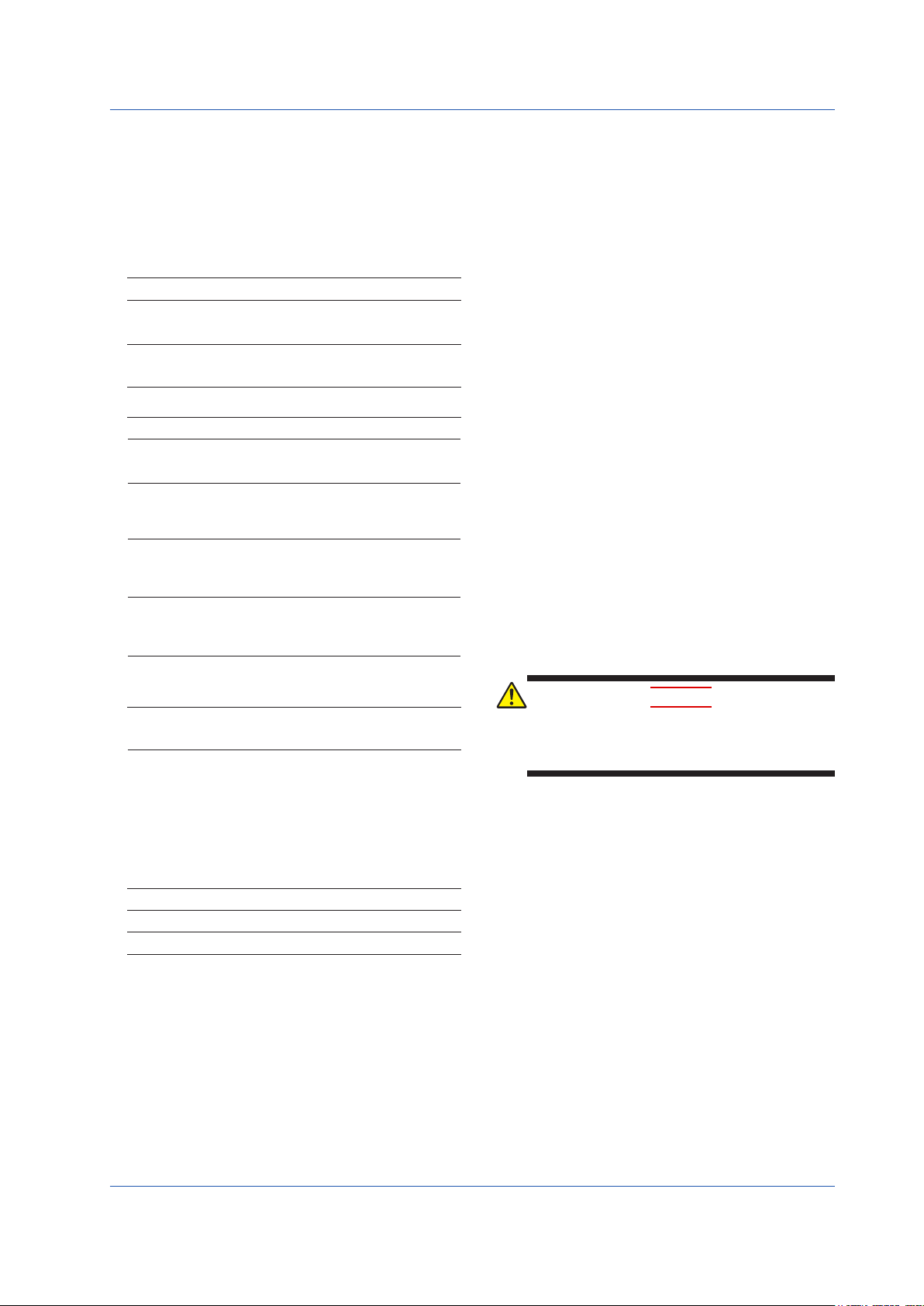
YS1500/YS1700 Main Unit
TheYS1000seriesmainunits havenameplatesaxedtothetopsof
the terminals.
Check the model and suffix codes inscribed on the nameplate to
conrmthattheproductreceivedisthatwhichwasordered.
Nameplate
No. (Instrument number)
When contacting your sales representative, inform them of this
number too.
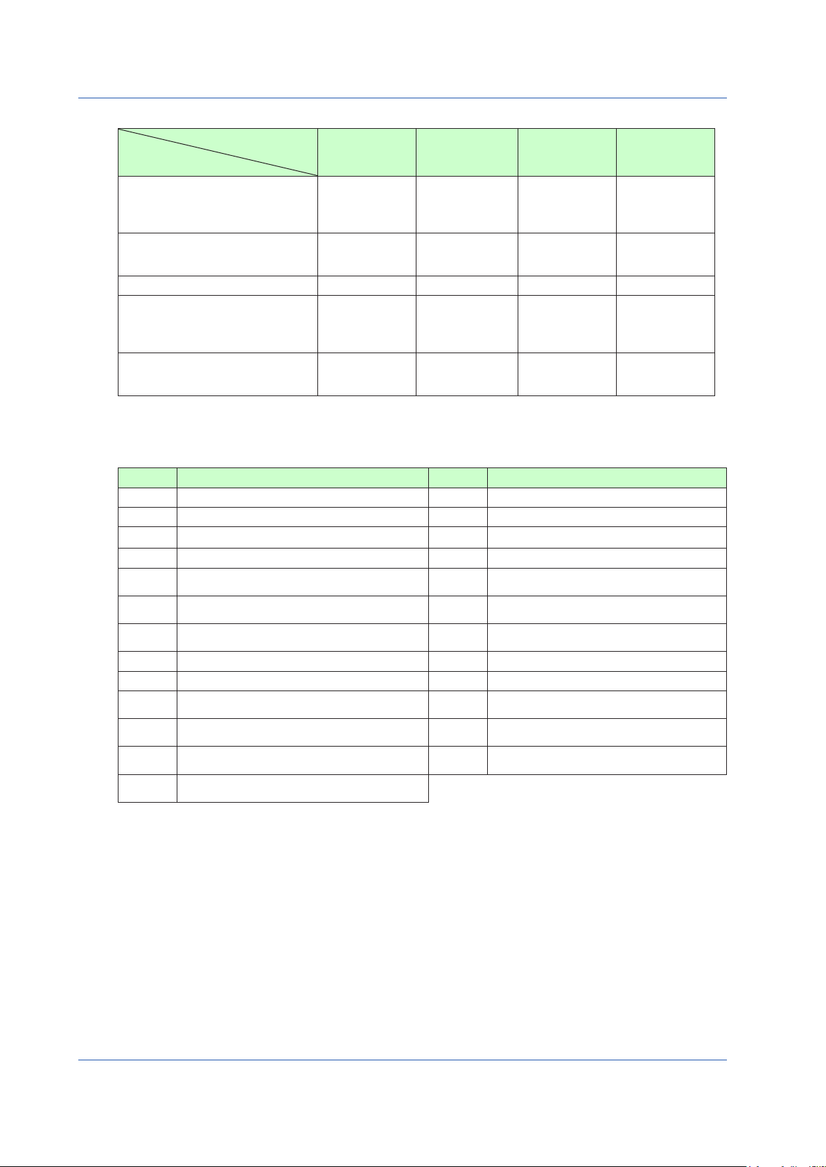
ModelandSuxCodes
Model
YS1700
YS1500
Use
Type
Power supply
Direct input (*4)
Communication
Certification
*1
Suffix
-1
-2
Only YS1700 is compatible. The expandable I/O terminal (model YS010)
and expandable I/O cable (model YS011) (cable length: 3 m) are provided.
Code
0
1
2
3
4
5
0
1
Optional
Code
/A01
/A02
/A03
/A04
/A05
/A06
/A07
/A08
/DF
/A31
/A32
/A34
/FM
/CSA
Remarks
Programmable indicating controller
Indicating controller
With hard manual unit
Without hard manual unit
Basic type
Basic type with expandable I/O (*1)
Compatible type for YS100 (with
YS100 case)
Compatible type for YS80 internal unit/
compatible type for EBS, I, EK, and
HOMAC (*2)
Compatible type for YS80 (compatible
size for YS80 with YS100 terminal)
Compatible type for pneumatic 100
line (with YS100 terminal) (*3)
100 V AC, 24 V DC common power
220 V AC power
mV input
Thermocouple input
RTD input
Potentiometer input
Isolator
Two-wire transmitter input (isolated)
Two-wire transmitter input (non-isolated)
Frequency input (*11)
Direct input with Fahrenheit
temperature range function (*5)
RS-485 communication (PC-link,
Modbus, YS protocol, and Peer-toPeer) (*6)
DCS-LCS communication (*7)
Ethernet communication (Modbus/
TCP) (*8)
FM nonincendive approved (FM Class
I, Div 2) (*9)
CSA safety and nonincendive
approved (Class I, DIV 2) (*10)
*2 This type can be connected to the YS80 housing (model SHUP).
(The EK/HOMAC-compatible housing (SHUP-420) and EBS/I
series-compatible housing (SHUP-100) are sold separately.)
The 100 line-compatible housing (model YS006) is sold separately.
*3
*4 Direct input options can be combined only with suffix codes “-2,”
“-4,” or “-5.” Selection of multiple options is not possible.
Optional code /DF can be combined only with optional code /A02 or /A03.
*5
*6 A combination with suffix code “-3” is not possible. Optional
codes /A31 and /A32 cannot be simultaneously specified. Please
specify the communication options /A31 (RS-485 communication)
to directly communicate with the CENTUM CS3000/VP.
*7 Optional codes /A31 and /A32 cannot be simultaneously
specified. Please specify the communication options /A32 (DCSLCS communication) to communicate with the CENTUM CS3000/
VP through the SCIU.
Optional code /A34 can be specified only for suffix codes “-0” or “-1.”
*8
*9
Optional code /FM can be combined only with suffix codes “-0” or “-1.”
*10 This option can be combined only with suffix codes “-0,”
“-1,” “-2.” However, certification is planned for the
combination of suffix code -2 and optional code /CSA.
*11 When option code /A08 is specified, the conformity to CE marking
is excluded
For the installation and wiring of YS1500/YS1700-2, -3,
-4, or -5, see the YS1000 Series Replacement Manual.
■CustomizedProduct
/S#,/Z:Customizedproduct;detailsinFX1-XJYS1700.xxx*
* Contact your supplier in case your instrument has option /S#
(where‘#’is anumber),and youare notinthe possessionof FX1XJYS1700.xxx.(where "xxx"is a unique document number and
option/S#or/Zisidentiedbythecoverpageofthatdocument.)
IM 01B08B02-01EN
5
Page 9
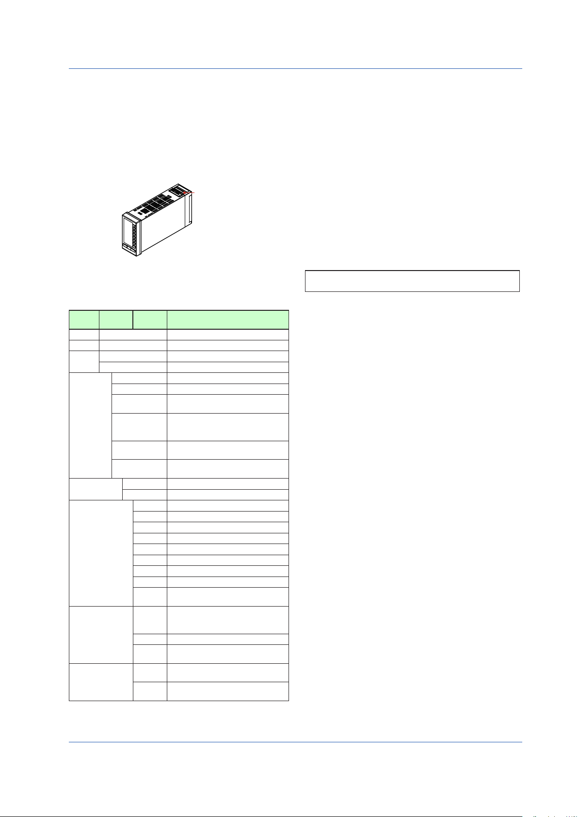
Accessories
0002E.ai
1
2 3
The product is provided with the following accessories according to
themodelandsuxcodes(seethetablebelow).Checkthatnoneof
them are missing or damaged.
TAG NO.
TAG NO.
TAG NO.
TAG NO.
4 5
7
YS1500 Indicating Controller
YS1700 Programmable
Indicating Controller
Operation Guide
8
6
Symbols Used in This Manual
This symbol is used on the instrument. It indicates the possibility of
injuryto the userordamage to theinstrument,and signies thatthe
user must refer to the user’s manual for special instructions. The
same symbol is used in the user’s manual on pages that the user
needs to refer to, together with the term “WARNING” or “CAUTION.”
WARNING
Calls attention to actions or conditions that could cause serious or
fatal injury to the user, and indicates precautions that should be taken
to prevent such occurrences.
CAUTION
Calls attention to actions or conditions that could cause injury to
the user or damage to the instrument or property and indicates
precautions that should be taken to prevent such occurrences.
Note
Identiesimportantinformationrequiredtooperatetheinstrument.
No. Item Name
Part
Number/
Q’ty Remarks
Model
Metal clamps
1
L4041RA 2
E9760RJ 2
E9760RN 2
E9760RJ 1
E9760RP 1
Tag plate seals
2
Range entry seals
3
Expandable I/O
4
terminal
Expandable I/O
5
cable
RJC sensor
6
L4041UA
YS010 1
YS011-03 1
L3501RA 1
Ferrite core
7
YS1500/YS1700
8
Operation Guide
*1:
For the RJC mounting, see the chapter “Installation and Wiring” in this
A1179MN 1
– 1
manual or the YS1000 Series Replacement Manual.
For YS100-0, or
YS100-1
For YS100-2
For YS100-4
4 50 × 3.5 mm
4 34 × 2 mm
Supplied with YS1700-
.
1
Cable length: 3 m
Supplied with YS1700-1.
Supplied with products with
optional code /A02. (*1)
For direct input cable
(Supplied with products
with optional code /A0
This user’s manual, A4
size
Indicates related operations or explanations for the user’s reference.
Indicates a character string displayed on the display.
[ ]
Setting Display
Indicates a setting display and describes the keystrokes required to
display the relevant setting display.
Perform the operations in chronological order. This section describes
the procedure under the assumption that these steps are being
takenforthersttime.Therearecaseswherenotallofthestepsare
required, depending on the required operation.
.
)
Setting Details
Provides the descriptions of settings.
Description
Describes restrictions, etc. regarding a relevant operation.
Accessories (sold separately)
The following lists accessories that are sold separately. When
ordered, check that none of them are missing or damaged. To inquire
about the accessories or about how to place an order, contact your
sales representative.
No. Item Name Model
120Ωterminating
1
resistor (*1)
YS020 1
Sales
Unit
Remarks
For RS-485
communication
About an Electronic Manual
User’s manuals for YS1000 are available on the following web site:
www.yokogawa.com/ns/ys/im/
You need Adobe Reader 7.0 or later (but the latest version is
recommended) installed on the computer in order to open and read
the manuals.
For a built-in 24 V
250Ωshuntresistor
2
YS021 1
transmitter power
supply
*1 The instrument has a built-in terminating resistor, which can be
selected for use by setting the relevant parameter. If a terminating
resistor is used in another device at the termination of the same
communication system, an external terminating resistor needs to
be provided to match the terminating resistance of the YS1000’s
built-in terminating resistor.
6
IM 01B08B02-01EN
Page 10

Introduction to Functions
The YS1000 series is a series of single-loop controllers to meet the demands of users’ consistently advancing and diversifying
needs. It is capable of the flexible control computation required for process control.
Features
• Color LCD display
The monitoring and operation display is provided in color, and input and output values, various constants, and incorporated
control functions can be set freely using key switches on the front panel. The monitoring displays include LOOP Display,
TREND Display, ALARM Display, and METER Display which provides information in much the same way as analog meters.
• Failsafe function
Two CPUs are configured to provide manual operations and displays even if one of the CPUs becomes faulty. Moreover, be-
cause the instrument incorporates a hard manual circuit independent of the digital circuit, it can continue to generate manipulated output variables even if the digital circuit that includes the CPUs fails.
• AC/DC-common power supply with wide operating voltage range.
The instrument can be powered by either AC (100 V AC) or DC (24 V DC).
• The front panel is dust- and water-proof (conforming to IP54).
• Abundant communication functions
The instrument can incorporate Ethernet (Modbus/TCP) communication, serial communication (Modbus, PC-link, and YS
protocol), and DCS-LCS communication.
• Control functions and abundant computation functions
The instrument is capable of single-loop, cascade, selector, and programmable control functions.
It can also perform computations such as the four arithmetic operations, logic computation, exponent, logarithm, temperature
compensation, pressure correction, etc. and peer-to-peer communication. (Optional YSS1000 Setting Software is required.)
Introduction to Functions
• Number of I/O points
Use of YS1700’s expandable I/O terminal allows the use of a maximum of eight analog inputs, a maximum of four analog
outputs, and a maximum of 14 DIOs.
Definition of Terms
• PV: Process variable input from process
• SV: Setpoint regarded as a control target
• MV: Manipulated variable for operating control elements such as valves.
• PID control: Control system based on action which combined three elements: proportional (P) action, integral (I) action, and
derivative (D) action.
• M mode: Mode in which manipulated output variables are operated manually.
• A mode: Mode in which MV is automatically controlled based on YS1000’s setpoint
• C mode: Mode in which MV is controlled based on an external setpoint
• Multi-function mode: Modes of the three preinstalled functions (single-loop mode, cascade mode, and selector mode)
• Programmable mode: Mode in which input/output or control computation is programmed
• User program: A program created using the YSS1000 Setting Software (available as an option)
IM 01B08B02-01EN
7
Page 11
Part Names
0201E.ai
Front Panel
0202E.ai
0203E.ai
0204E.ai
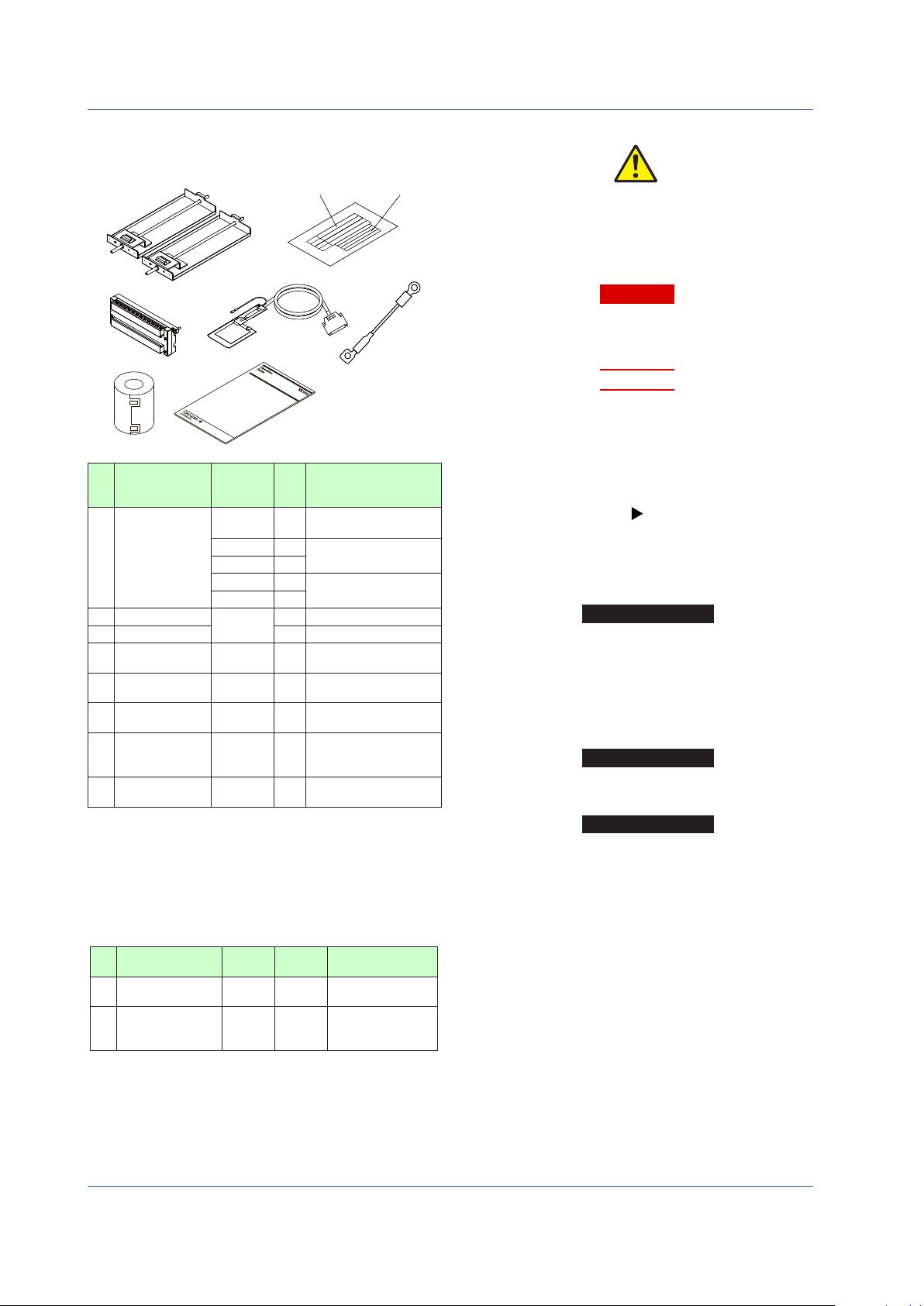
Front Panel Part Names
(12)
(1)
(9)
(10)
(11)
Figure 2.1
(2)
(3)
(4)
(5)
(6)
(7)
(8)
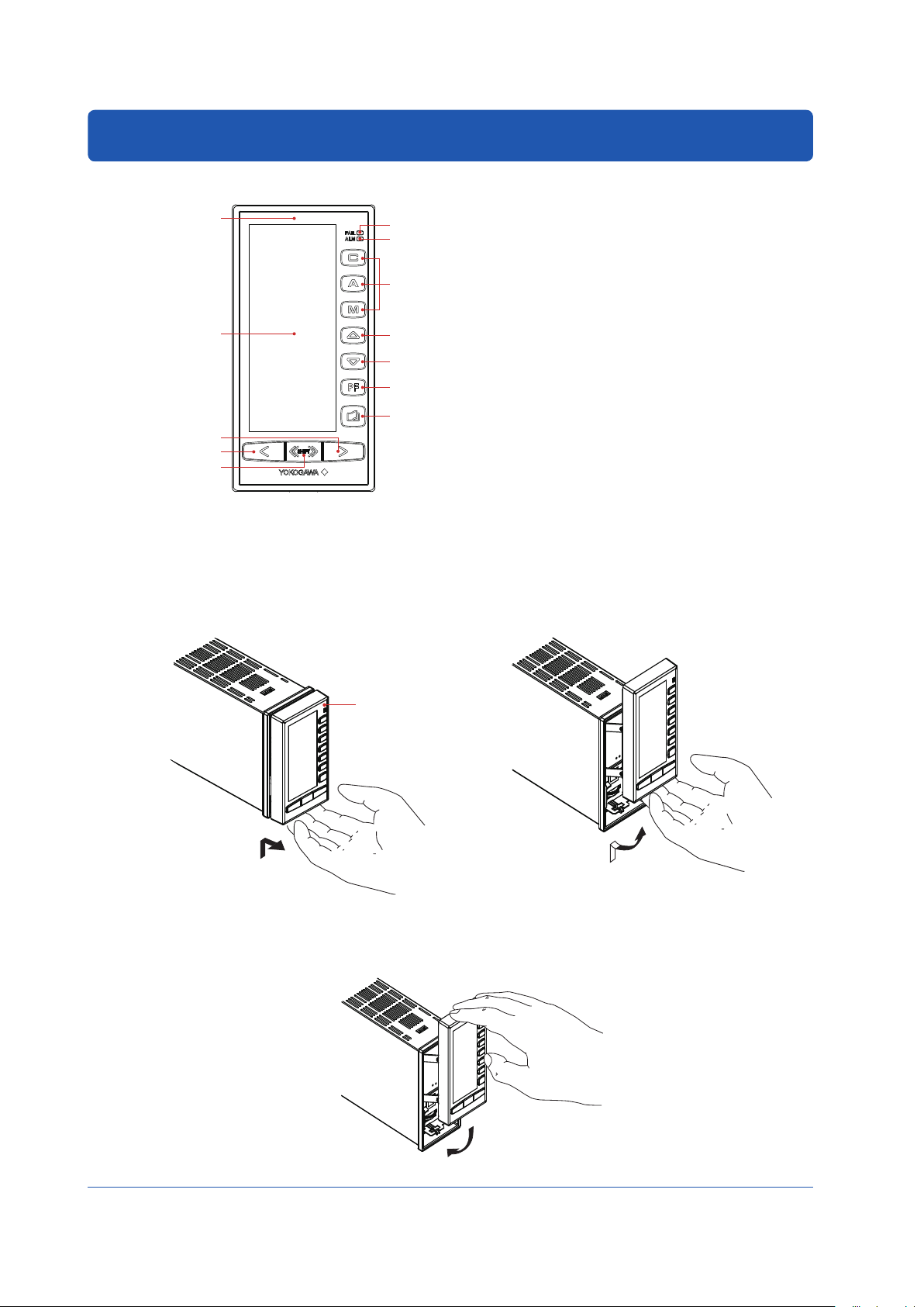
Swinging the Front Panel Up and Down
Swinging up the front panel
1.
Press upwards in the center of the bottom of the front panel. You can draw the front panel toward you until you feel a slight
resistance and the movement of the front panel will stop.
(You can swing up the front panel more smoothly if hold the top and bottom of the front panel.)
2.
Swing the front panel up and out from that position.
(1) Color LCD display: 120 × 320 dots
(2) FAIL lamp (LED: red)
(3) ALM lamp (LED: yellow)
(4) C mode key, A mode key, M mode key, and LED indicators
(C: green, A: green, M: yellow)
(5) SV increase key
(6) SV decrease key
(7) PF key and LED indicator
(8) Page key
(9) MV increase key
(10) MV decrease key
(11) Fast-change key/SHIFT key
(12) TAG label (recommended position to attach label)
► Forthefunctionsofeachpart:see“MonitoringandControl
of Regular Operations (Operation Display)” in this manual.
Figure 2.3
Figure 2.2
Swinging down the front panel
Push down on the center of the top of the front panel. When you feel a slight sense of resistance, stop pushing. Slide it forward
from that position. It will click into place, indicating that it is locked.
Figure 2.4
8
8
IM 01B08B02-01EN
Page 12
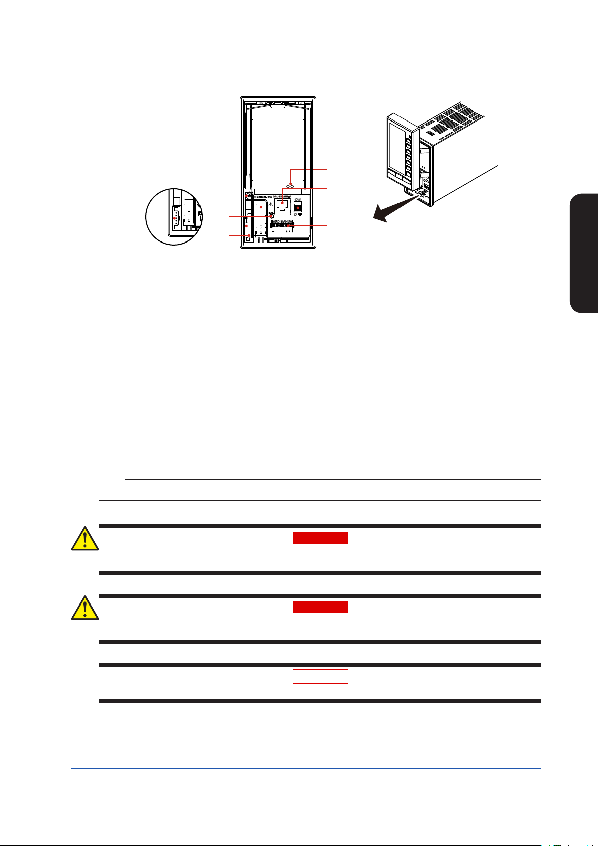
Part Names of the Internal Panel Seen with the Front Panel Swung up
0205E.ai
(9)
Part Names
(1)
(7)
(5)
(3)
(8)
(4)
(6)
(3)
(2)
Figure 2.5
(1) Connector for connection to a PC (PROGRAMMER)
This is a communication cable connector for downloading, uploading, or monitoring parameters or user programs set using
the YSS1000 Setting Software.
► YSS1000:YSS1000SettingSoftware/YS1700ProgrammableFunctionUser’sManual
(2) Metal lever
Touch the metal lever to discharge static electricity. Before you connect the cable to the YS110 connector, touch the metal
lever.
(3) Connector for YS110 standby manual station (MANUAL STA)
(4) Internal unit release lever
(5) Hard manual operation wheel (HARD MANUAL)
An operation wheel to manipulate an output
(6) MV balance lamp (BAL) (Color: green)
Lights up when a manipulated output variable and the hard manual unit’s output value agree with each other.
(7) Hard manual selector switch (ON/OFF)
The switch used to switch to a manipulated variable (MV) set using the hard manual operation wheel.
(8) An internal unit fixing screw
(9) LED and switch for repair
Contact us for repair.
► Regardingitems(2),(3),(5),(6),and(7)above:see“BackupOperationintheEventofInstrumentFailure”inthismanual.
Note
For products with suffix code -2xx, there are no hard manual unit-related parts ((5), (6), and (7)).
Part Names
Do not remove the internal unit from the instrument case. Contact YOKOGAWA’s sales office or sales representative when
removing the internal unit, as safety standard inspection is required.
Explosionhazard.
Do not remove or insert the internal unit in explosive atmospheres.
Products with optional code /FM or /CSA cannot satisfy the explosion protection standards if the internal unit is removed.
IM 01B08B02-01EN
WARNING
WARNING
CAUTION
9
Page 13
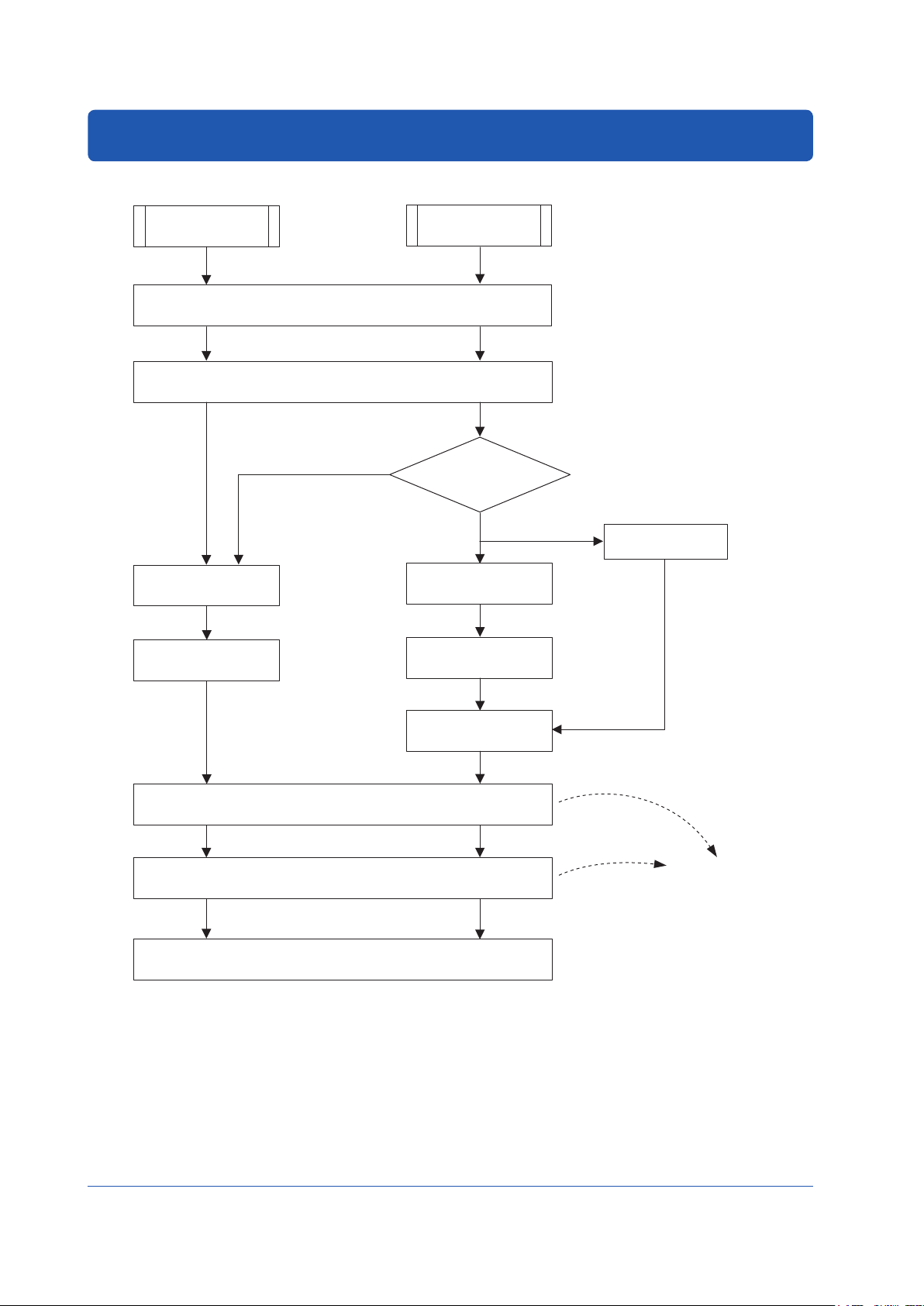
YS1500/YS1700 Operating Procedure
YS1500 or
YS1700
Tuning/operations can be
0301E.ai
When using the instrument for the first time, proceed according to the following sequence:
YS1500
Unpack the instrument and check the specifications
Turn ON power supply
Select the
multi-function mode
► Setting the Controller Mode (p.36)
Multi-function mode has
the following three modes:
• Single-loop mode
• Cascade mode
• Selector mode
Installation
No
YS1700
► Checking the Contents of the Package (p.5)
► Installation and Wiring (p.42)
Will you create
user programs?
Yes
YS1700
Turn ON power supply
Select the
programmable mode
► Seting the Controller Mode (p.36)
Write user programs
► YSS1000 Setting Software/YS1700 Programmable
Function User’s Manual
YSS1000
Setting Software (PC)
Create
user programs
► YSS1000 Setting
Software/YS1700
Programmable
Function User’s
Manual
10
10
Set up engineering constants
Start tuning/operation
Regular operation
► Operating the Engineering
Displays (from p.36)
set using the YSS1000
Setting Software.
► Operating the Tuning Displays
(from p.32)
Tuning Guide (from p.40)
► Monitoring and Control of Regular Operations (from p.16)
Figure 3.1
► YSS1000 Setting
Software/YS1700
Programmable Function
User’s Manual
IM 01B08B02-01EN
Page 14
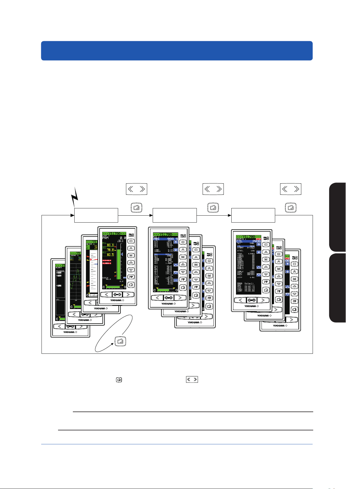
Basic Operation
Power ON
0401E.ai
SHIFT
Overview of Display Switching and Operation Keys
The YS1000 has the following three display groups:
(1) Operation Display Group
This group has a LOOP Display which allows operation mode switching during control operation, SV setting, and MV opera-
tion; a TREND Display which displays the trends of PV, SV, and MV; an ALARM Display which displays detailed alarm infor-
mation; a LOOP Display which displays two loops simultaneously (operation is on a loop basis); and a METER Display which
displays PV, SV, and MV on a meter scale using a pointer.
(2) Tuning Display Group
This group has a display for setting and displaying control parameters such as PID, and a display for monitoring input/output
signals.
(3) Engineering Display Group
This group has a display for setting up functions as a controller, a display for setting and displaying various registers and vari-
ous tables, a display for setting input specifications and a password setting display.
Selecting a Display
The flow of display selecting operations is as follows:
SHIFT
SHIFT
SHIFT
+ + +
Operation Display
group
C
Tuning Display
group
For operations of the Tuning Display and Engineering Display groups, see
“Operating the Tuning Displays” and “Operating the Engineering Displays .”
Engineering Display
group
YS1500/YS1700 Operating
Procedure
Basic Operations
Basic Operations
Figure 4.1
When the instrument’s power is turned ON, the Operation Display appears.
1.
Each time the Page key ( ) is pressed with the SHIFT key (
2.
The display changes in the order of Operation Display, Tuning Menu Display, and Engineering Menu Display, after which the
Operation Display reappears.
) held down, the display is switched.
Note
Operation of the SHIFT key + Page key (a two key keystroke) implies that you should press the Page key with the SHIFT key
held down. Doing so in the opposite order does not switch the display.
IM 01B08B02-01EN
1111
Page 15

Basic Operations
Software keys
Software keys are keys displayed on the LCD. The functions of the software keys are assigned to the operation keys on
the right of the display.
In the figure at the left, the ↑ (UP) software key corresponds with the
mode key.
Figure 4.2
0402E.ai
12
IM 01B08B02-01EN
Page 16
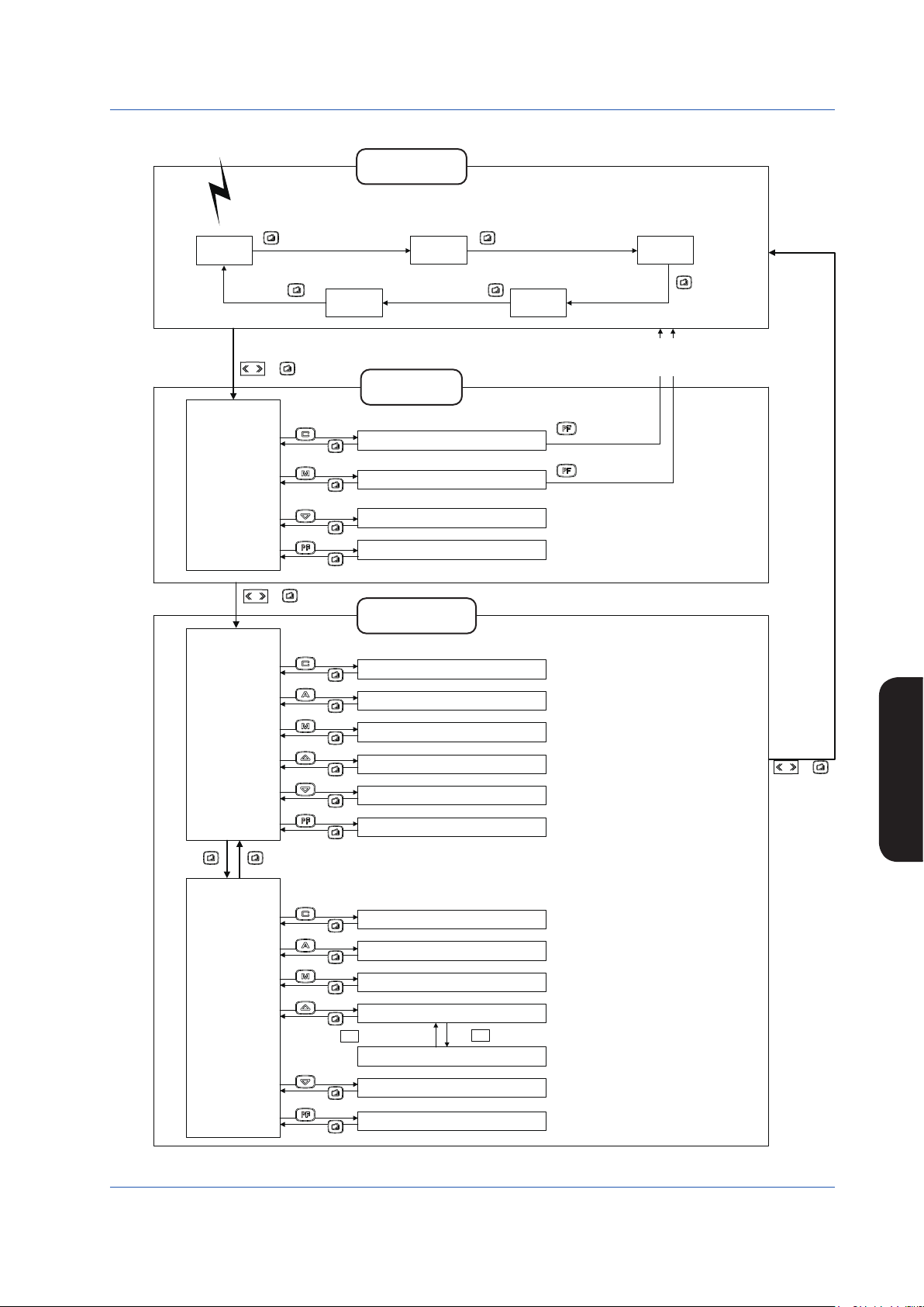
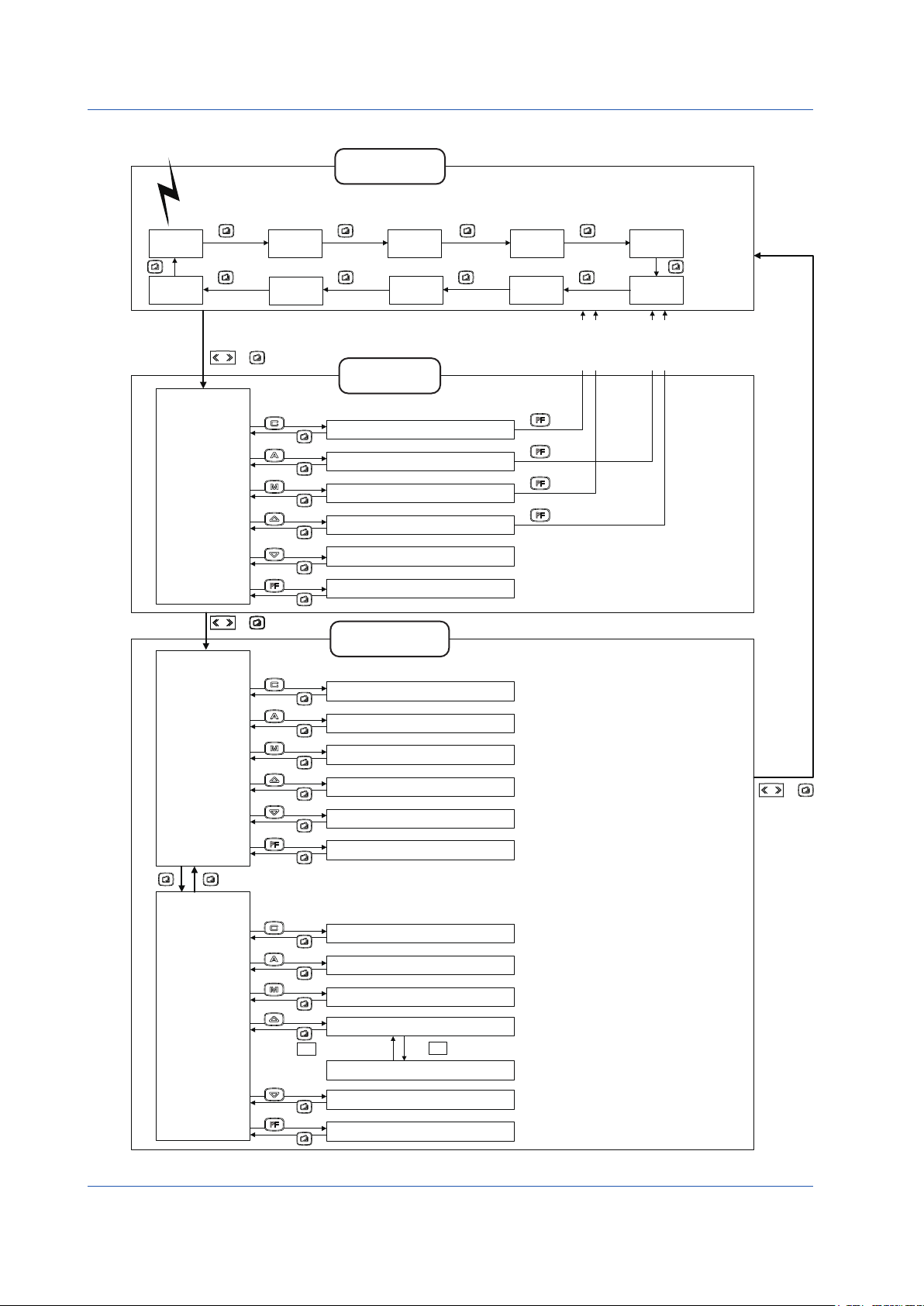
DisplaySwitchinginSingle-loopMode(YS1500’sfactorysetting)
Power ON
0403E.ai
Operation Display
LOOP1
Display
group
METER1
Display
The turning ON/OFF of each Operation Display and the initial
Operation Display which appears when the power is turned
on can be set.
► Settings and description: YS1500 Indicating Controller/
YS1700 Programmable Indicating Controller User’s
Manual
Basic Operations
TREND1
Display
SHIFT
Tuning Menu
Display
[PID1]
[STC1]
[PARAMETER]
[I/O DATA]
SHIFT
Engineering
Menu Display 1
[
CONFIG1]
[CONFIG2]
[CONFIG3]
[SC MAINT ]
[PASSWORD]
[SMPL]
+
PARAMETER
I/O DATA
+
CONFIG1
CONFIG2
CONFIG3
SC MAINT
PASSWORD
PID1
STC1
SMPL
ALARM
Display
Tuning Display
group
PID Setting Display 1
STC Setting Display 1
Parameter Setting Display
Input and Output Data Display
Engineering Display
group
Function Setting Display 1
Function Setting Display 2
Function Setting Display 3
Input Specification Setting Display
Password Setting Display
Sample Setting Display
TREND3
Display
To the LOOP 1, TREND 1, or METER 1 Display
(To an Operation Display on which the Tuning Menu
Display is selected for the first time)
OPE
OPE
Basic Operations
SHIFT
+
IM 01B08B02-01EN
Engineering
Menu Display 2
[DISPLAY]
[LCD]
[COMM]
[DI/DO]
[LCD MAINT]
[FX TABLE]
DISPLAY
LCD
COMM
DI/DO
Setting Display for Operation Display
LCD Setting Display
Communication Setting Display
DI/DO Setting Display 1/2
↑
Press at the first line and at the last line.
LCD MAINT
DI/DO Setting Display 2/2
↓
LCD Maintenance Display
FX TABLE
FX Table Setting Display
Figure 4.3
13
Page 17
Power ON
Basic Operations
Display Switching in the Cascade or Selector Mode
Operation Display
group
+
STC2
PARAMETER
I/O DATA
LOOP2
Display
DUAL1
Display
PID1
PID2
STC1
Tuning Display
group
PID Setting Display 1
PID Setting Display 2
STC Setting Display 1
□
STC Setting Display 2
Parameter Setting Display
Input and Output Data Display
LOOP1
Display
□
DUAL2
Display
SHIFT
Tuning Menu
Display
[PID1]
[PID2]
[STC1]
[STC2]
[PARAMETER]
[I/O DATA]
METER1
Display
ALARM
Display
The turning ON/OFF of each Operation Display and the initial
Operation Display which appears when the power is turned
on can be set.
► Settings and description: YS1500 Indicating Controller/
YS1700 Programmable Indicating Controller User’s Manual
METER2
Display
TREND3
Display
To the LOOP1, TREND1, METER1,
or DUAL 1 Display (To an Operation
Display on which the Tuning Menu
Display is selected for the first time)
OPE
OPE
OPE
OPE
TREND1
Display
TREND2
Display
To the LOOP2, TREND2, METER2,
or DUAL 2 Display (To an Operation
Display on which the Tuning Menu
Display is selected for the first time)
SHIFT
Engineering
Menu Display 1
[CONFIG1]
[CONFIG2]
[CONFIG3]
[SC MAINT ]
[PASSWORD]
[SMPL]
Engineering
Menu Display 2
[DISPLAY]
[LCD]
[COMM]
[DI/DO]
[LCD MAINT]
[FX TABLE]
+
Engineering Display
group
CONFIG1
CONFIG2
CONFIG3
SC MAINT
PASSWORD
Function Setting Display 1
Function Setting Display 2
Function Setting Display 3
Input Specification Setting Display
Password Setting Display
SMPL
Sample Setting Display
DISPLAY
Setting Display for Operation Display
LCD
LCD Setting Display
COMM
DI/DO
Communication Setting Display
DI/DO Setting Display 1/2
↑
Press at the first line and at the last line.
LCD MAINT
FX TABLE
DI/DO Setting Display 2/2
LCD Maintenance Display
↓
FX Table Setting Display
* Not displayed in Selector mode.
SHIFT
+
0404E.ai
14
Figure 4.4
IM 01B08B02-01EN
Page 18
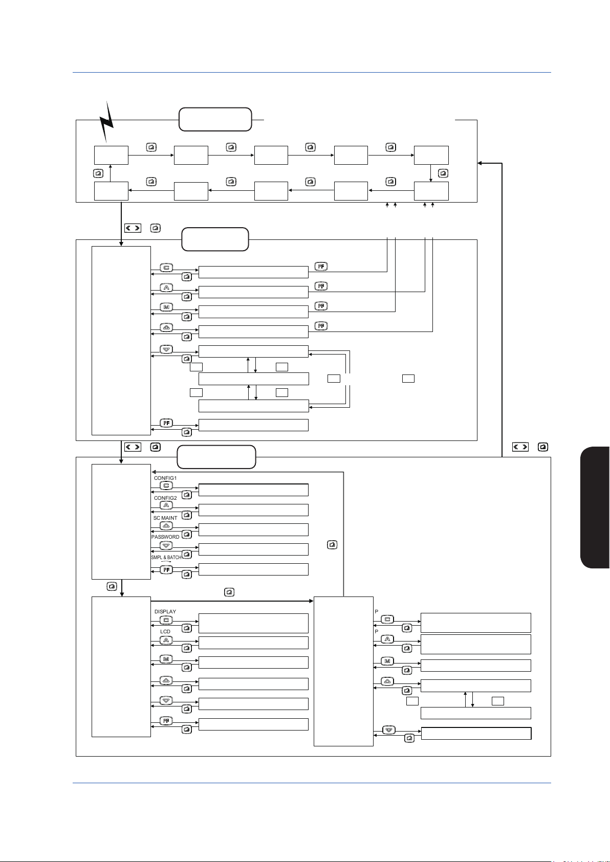
Display Switching in the Programmable Mode (YS1700’s factory setting)
Power ON
0405E.ai
The turning ON/OFF of each Operation Display and the
initial Operation Display which appears when the power is
turned on can be set.
► Settings and description: YS1500 Indicating Controller/
YS1700 Programmable Indicating Controller User’s Manual
METER1
Display
METER2
Display
LOOP1
Display
Operation Display
group
LOOP2
Display
Basic Operations
TREND1
Display
DUAL2
Display
SHIFT
Tuning Menu
Display
[PID1]
[PID2]
[STC1]
[STC2]
P&T REG]
[
[I/O DATA]
SHIFT
Engineering
Menu Display 1
[CONFIG1]
[CONFIG2]
[SC MAINT ]
[PASSWORD]
[SMPL & BATCH]
DUAL1
Display
+
Tuning Display
ALARM
Display
To the LOOP1, TREND1, METER1,
or DUAL 1 Display (To an Operation
Display on which the Tuning Menu
Display is selected for the first time)
group
PID1
PID2
STC1
STC2
PID Setting Display 1
PID Setting Display 2
STC Setting Display 1
STC Setting Display 2
P&T REG
P&T Register Display 1/3
↑
Press at the first line.
Press at the last line.
P&T Register Display 2/3
↑
Press at the first line. Press at the last line.
I/O DATA
P&T Register Display 3/3
I/O Data Display
+
Engineering Display
group
CONFIG1
CONFIG2
SC MAINT
PASSWORD
SMPL & BATCH
Function Setting Display 1
Function Setting Display 2
Input Specification Setting Display
Password Setting Display
Sample & Batch Setting Display
OPE
OPE
OPE
OPE
↓
Press at the last line.
↓
TREND3
Display
↓
TREND2
Display
To the LOOP2, TREND2, METER2,
or DUAL 2 Display (To an Operation
Display on which the Tuning Menu
Display is selected for the first time)
↑
Press at the first line.
SHIFT
+
Basic Operations
Engineering
Menu Display 2
[DISPLAY]
[LCD]
[COMM]
[
GX1 TABLE]
[GX2 TABLE]
[FX TABLE]
IM 01B08B02-01EN
DISPLAY
LCD
COMM
GX1 TABLE
GX2 TABLE
FX TABLE
Setting Display for Operation
Display
LCD Setting Display
Communication Setting Display
GX1 Table Setting Display
GX2 Table Setting Display
FX Table Setting Display
Engineering
Menu Display 3
[PGM1 SET]
PGM2 SET]
[
[
PID TABLE]
[
K CONST]
[LCD MAINT]
Figure 4.5
PGM1 SET
Program-setting-unit 1
PGM2 SET
Setting Display
Program-setting-unit 2
PID TABLE
K CONST
Setting Display
Preset PID Setting Display
K-constant Display 1/2
↑ ↓
Press at the first line. Press at the last line.
LCD MAINT
K-constant Display 2/2
LCD Maintenance Display
15
Page 19
Monitoring and Control of Regular Operations
(22) Key LOCK status display
0501E.ai
(Operation Display)
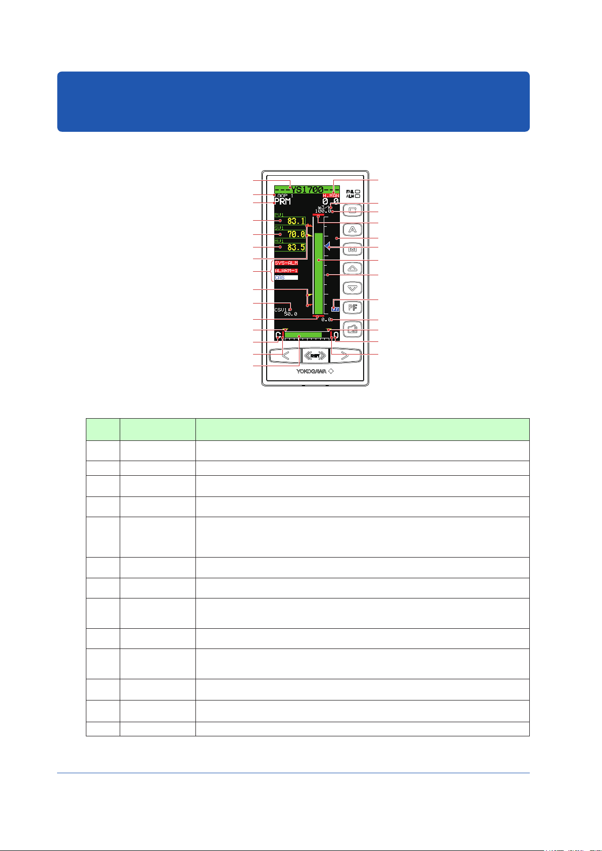
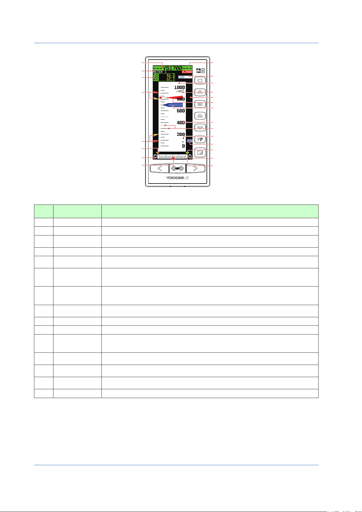
Monitoring and Operating the Operation Display
Monitoring and Operating the LOOP Display
Tag number (1)
Display title (2)
P-register display (18)
PV digital display (3)
SV digital display (7)
MV digital display (9)
HH pointer, PH pointer (5)
Alarm generation display,
control status display
LL pointer, PL pointer (5)
Cascade setting input value (20)
PV underflow (6)
ML pointer (11)
MV valve direction (13)
MV underflow (12)
MV bar, MV scale (10)
(17)
(19) Operation status display
(14) Engineering units
(16) 100% value of scale
(6) PV overflow
(8) SV pointer
(4) PV bar
(15) PV bar scale
(21) PF key function display
(16) 0% value of scale
(11) MH pointer
(13) MV valve direction
(12) MV overflow
Figure 5.1
Table 5.1
No. in
Figure
(1) Tag number
Name Description
A tag number combining alphanumeric characters and symbols having a maximum of 12 digits
is displayed on a loop basis.
(2) Display title The title of the display being shown is indicated.
(3) PV digital display
(4) PV bar
A PV value is displayed in engineering units in a digital value of five significant digits (seven
digits including a sign and decimal point).
A PV value is displayed in a bar. The bar display is in 200 dots at full scale (100%) and
increases/decreases on a dot (0.5%) basis.
PH values (high limit alarm setpoints for PV) and PL values (low limit alarm setpoints for PV) are indicated
PH, PL, HH, and LL
(5)
pointers
with triangular pointers, while HH values (high-high limit alarm setpoints for PV) and LL values (low-low
limit alarm setpoints for PV) are indicated with pointers which are overlapped pairs of triangles. Pointers
are clipped and displayed at 0% if PV values are below 0%, or displayed at 100% if they exceed 100%.
PV underflow and
(6)
PV overflow
(7) SV digital display
A PV underflow is displayed if a PV value is below 0%, while a PV overflow is displayed if it
exceeds 100%.
An SV value is displayed in engineering units in a digital value of five significant digits (seven
digits including a sign and decimal point).
SV values are indicated with triangular pointers. The pointer display moves up and down with
(8) SV pointer
a resolution of 0.5%. Pointers are clipped and displayed at 0% if SV values are below 0%, or
displayed at 100% if they exceed 100%.
(9) MV digital display
MV bar
(10)
MV scale
(11) MH and ML pointers
MV underflow and
(12)
MV overflow
An MV value is displayed in a digital value of four significant digits (six digits including a sign
and decimal point, with the number of decimal places fixed to one digit) in a % display.
An MV value is displayed in a bar. The bar display is in 80 dots (100%) at full scale, divided into
20 blocks (5%) for display. It increases/decreases on a dot (1.25%) basis. A scale divided into
10 (10% segments) is also displayed.
MH values (high limit setpoints of MV) and ML values (low limit setpoints of MV) are indicated
with triangular pointers.
An MV underflow is displayed if an MV value is below 0%, while an MV overflow is displayed if it
exceeds 100%.
(13) MV valve direction MV valve direction is displayed as [C] (closed) or [O] (open). The valve direction can be set.
16
16
IM 01B08B02-01EN
Page 20
Monitoring and Control of Regular Operations (Operation Display)
Table 5.2
No. in
Figure
Name Description
(14) Engineering units Engineering units (UNIT) are displayed in a maximum of seven digits.
(15) PV bar scale The PV bar scale is displayed divided into a maximum of 10 segments (10% segments).
0% value of scale, 100%
(16)
value of scale
Alarm generation display,
(17)
Control status display
P-register display
(18)
0% value of scale (SCL) and 100% value of scale (SCH) are displayed in engineering units in
a digital value of five significant digits (seven digits including a sign and decimal point).
Alarm and control statuses are displayed in abbreviations. These vary according to
controller mode in the multi-function mode; or according to the control module in the
programmable mode. See Tables 5.3 to 5.5.
When this display is enabled, P register is displayed on the LOOP 1 and LOOP 2
Displays individually. This display is available in the programmable mode.
The controller operation status is displayed.
Display Description
[POWER DOWN] Power down is being detected. (1)
[H.MAN] Hard manual selector switch has been activated. (2)
Operation status display
(19)
(No indication) The instrument is operating.
[STOP] Operation stopped (such as while setting a
function on the Engineering Display, etc.)
Cascade setting input
(20)
value
[TEST1]
[TEST2]
When the instrument is used in the cascade mode, a cascade setting input value is
displayed in engineering units in a digital value of five significant digits (seven digits
including a sign and decimal point). No value is displayed in the programmable mode.
Test run mode 1 (only in the programmable mode)
Test run mode 2 (only in the programmable mode)
Simulation program is being executed
The key function is displayed. The key function display is different in the multifunction mode and the programmable mode.
1) Multi-function mode
The key function is set using the PF key function selection parameter [PFKEY].
(21)
key function display
When the STC mode selection is “not OFF” and the “ key has been set to STC”,
the function display becomes [STC]. In other cases, nothing is displayed.
2) Programmable mode
The key function can be defined in user programs.
The function display becomes [PF] in the programmable mode.
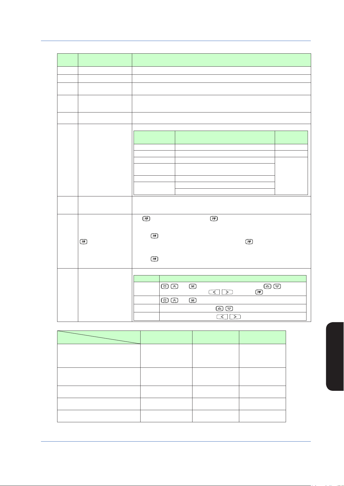
The key LOCK status is displayed.
Display Description
[ALLK]
Key LOCK status display
(22)
[MDLK]
[SVLK]
[MVLK]
Table 5.3 Alarm Display and Control Status Display in the YS1500/YS1700 Multi-function Mode
Controller Mode
Display Item
SYS-ALM
Alarm generation display (Note 1)
STC-ALM
ALARM-1
CAS
Control status display (Note 2)
SPC, DDC
BUA, BUM
Control substatus display 1
Control substatus display 2
Control substatus display 3
Note 1: This display appears only if an alarm occurs. If multiple alarms occur simultaneously, they are indicated in multiple lines.
Note 2: Only when the operation mode is in cascade setting automatic control (C mode) is a control status displayed, while nothing is indicated in
automatic control (A mode) or manual control (M mode).
IM 01B08B02-01EN
EXT-MAN,EXT-AUT
EXT-PMV,EXT-TRK
SV TRK, PV TRK OPEN, CLOSE
STC-ON, STC-DSP,
ATSTUP
, , and keys, SV increase and decrease ( , ) keys, MV
increase and decrease ( , ) keys, and key are disabled.
, , and keys are disabled.
SV increase and decrease (
MV increase and decrease (
, ) keys are disabled.
, ) keys are disabled.
Single Loop Cascade Selector
SYS-ALM
STC-ALM
ALARM-1
ALARM-2
CAS
SPC, DDC
BUA, BUM
SYS-ALM
STC-ALM
ALARM-1
ALARM-2
CAS
SPC, DDC
BUA, BUM
EXT-TRK,EXT-PMV EXT-TRK,EXT-PMV
SV2-RMT, SV2-LCL
SEL1, SEL2
STC-ON, STC-DSP,
ATSTUP
STC-ON, STC-DSP
Display
Priority Order
(3)
Monitoring and Control of
Regular Operations
17
Page 21
Monitoring and Control of Regular Operations (Operation Display)
Table 5.4 Alarm Display and Control Status Display in the YS1700 Programmable Mode
Control Module
Display Item
Alarm generation display (Note 1)
Control status display (Note 2)
Control substatus display 1
Basic Control
(BSC1)
SYS-ALM
STC-ALM
ALARM-1
CAS
SPC, DDC
BUA, BUM
None None None None
Cascade Control
(CSC)
SYS-ALM
STC-ALM
ALARM-1
ALARM-2
CAS
SPC, DDC
BUA, BUM
Selector Control
(SSC)
SYS-ALM
STC-ALM
ALARM-1
ALARM-2
CAS
SPC, DDC
BUA, BUM
SYS-ALM
STC-ALM
ALARM-1
ALARM-2
CAS
SPC, DDC
BUA, BUM
SV2-RMT
Control substatus display 2
None
OPEN, CLOSE
SV2-LCL
SEL1, SEL2
None
SEL-EXT
Control substatus display 3
STC-DSP
ATSTUP
Note 1: This display appears only if an alarm occurs. If multiple alarms occur simultaneously, they are indicated in multiple lines.
Note 2: Only when the operation mode is in cascade setting automatic control (C mode) is a control status displayed, while nothing is indicated in
automatic control (A mode) or manual control (M mode).
Table 5.5 Meaning of Display Abbreviations
STC-ON
STC-ON
STC-DSP
ATSTUP
STC-ON
STC-DSP
STC-ON
STC-DSP
ATSTUP
Symbol Meaning Symbol Meaning
SYS-ALM
STC-ALM
ALARM-1
ALARM-2
CAS
SPC
DDC
BUA
BUM
EXT-MAN
EXT-AUT
EXT-PMV
EXT-TRK
A system alarm occurred.
An STC alarm occurred.
A loop 1 process alarm occurred.
A loop 2 process alarm occurred.
Remote operation being conducted in response to
external setpoint input
Remote operation being conducted in response to
SV from a high-level device
Remote operation being conducted in response to
MV from a high-level device
Transition to backup auto status
Transition to backup manual status
Transition to manual control in response to external
digital input
Transition to automatic control in response to
external digital input
Preset MV being output in response to external
digital input
Output being tracked in response to external digital
input
SV TRK
PV TRK
OPEN
CLOSE
SV2-RMT
SV2-LCL
SEL1
SEL2
SEL-EXT
STC-ON
STC-DSP
ATSTUP
SV being tracked
PV being tracked
(Internal) cascade open
(Internal) cascade closed
Loop 2’s SV2 remote setting
Loop 2’s SV2 local setting
Loop 1 side’s selection status
Loop 2 side’s selection status
External signal selection status
STC control operation being conducted
PID setting target value is indicated by STC.
STC auto startup being conducted
DUAL-loop
Control (BSC1,
BSC2)
► Forcausesofalarmsthathaveoccurredandactionstobetaken:see“Troubleshooting”inthismanual.
18
IM 01B08B02-01EN
Page 22

Monitoring and Control of Regular Operations (Operation Display)
Operating the LOOP Display
This section describes keystrokes for performing various settings and operations on the LOOP Display.
(1) Switching the operation mode
M mode key: Switches the operation mode to manual control (M mode).
A mode key: Switches the operation mode to automatic control (A mode).
C mode key: Switches the operation mode to cascade setting automatic control (C mode).
Moreover, the LED inside the operation mode key corresponding to the current operation mode lights up.
Note
Ifacascadeinputsignalis−6.3%orlessor106.3%ormore,theoperationmodecannotbeswitchedtoCmode.
► Forswitchingtheoperationmode:see“SwitchingofOperationModes”inthismanual.
(2) SV setting operation
The SV setting key changes the setpoint (SV).
This key is enabled when the operation mode is in the A or M mode.
SV increase key: Increases an SV value.
SV decrease key: Decreases an SV value.
(3) MV operation
The MV operation key is used to manually operate a manipulated output variable (MV). This key is enabled when the opera-
tion mode is in the M mode.
MV increase key: Increases an MV value.
MV decrease key: Decreases an MV value.
Moreover, pressing an MV operation key with the
increase/decrease speed.
SHIFT
(fast-change key/SHIFT key) held down accelerates the MV-value
(4) PF key functions
The PF key functions are different in the multi-function mode and the programmable mode.
Multi-functionmode:
The PF key function is set on the Function Setting Display 3 (CONFIG 3). There are the following two parameter designations:
(1) No function: The PF key does not function.
(2) STC ON/OFF: The PF key switches STC operation ON/OFF.
If STC ON/OFF is specified, when STC is ON the LED inside the PF key lights up.
Programmable mode:
The PF key function is defined by user programs then used. The LED in the PF key can be turned ON/OFF by the user pro-
grams.
For cascade control, selector control, or dual-loop control, the loop 1 can be operated on the LOOP 1 Display, while the loop 2
can be operated on the LOOP 2 Display.
Monitoring and Control of
Regular Operations
IM 01B08B02-01EN
19
Page 23
Monitoring and Control of Regular Operations (Operation Display)
P
0502E.ai
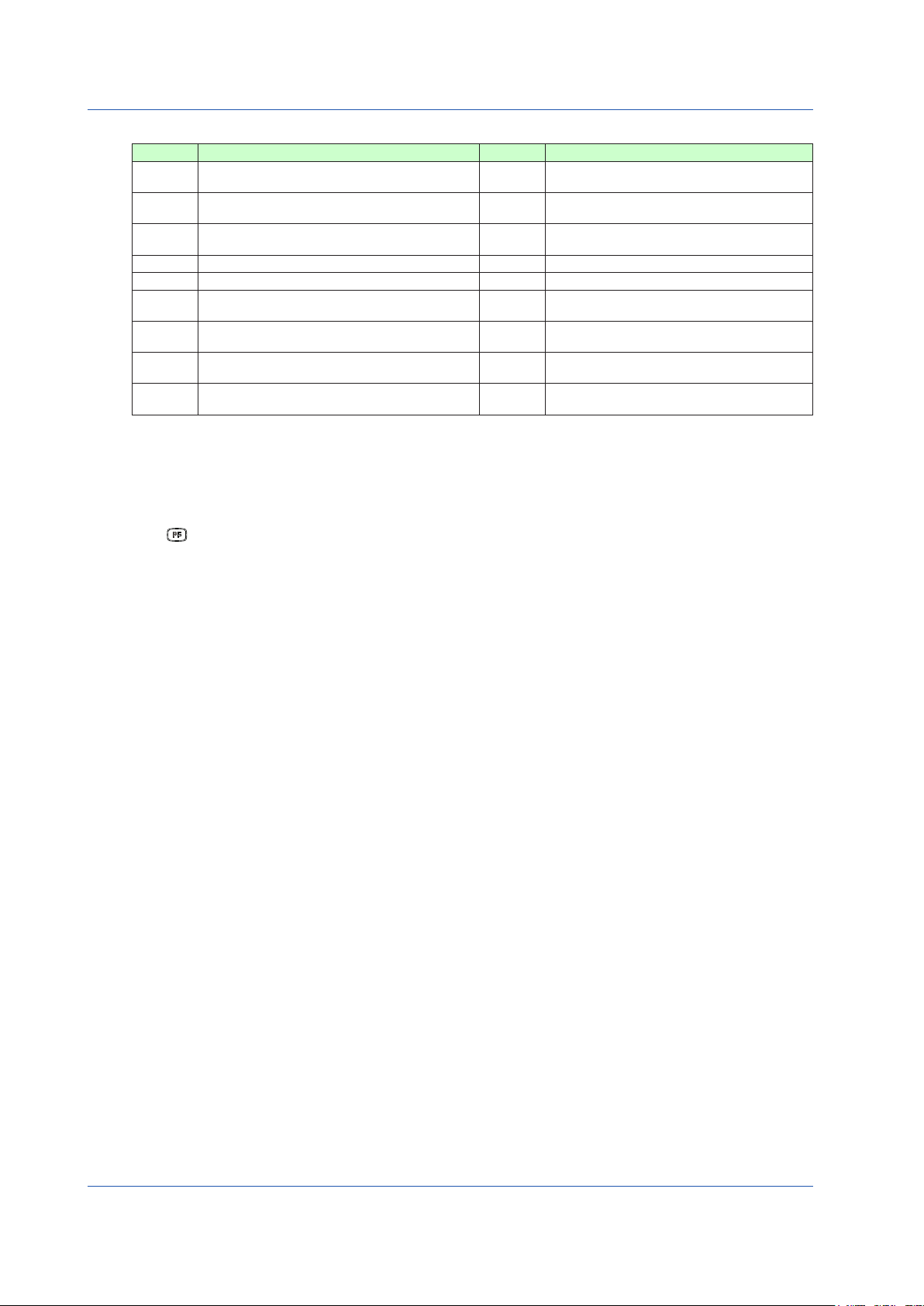
Monitoring and Operating the METER Display
Tag number (1)
Display title (2)
V, SV, MV digital display (3)
HH pointer, PH pointer (11)
LL pointer, PL pointer (11)
ML pointer (14)
MV valve direction (15)
MV pointer (13)
Figure 5.2
Table 5.6
No. in
Figure
Name Description
(1) Tag number As on the LOOP Display, a tag number appears here.
(2) Display title The title of the display being shown is indicated.
PV, SV, and MV
(3)
digital display
(4) PV meter scale
Main scale marks,
(5)
subscale marks
PV, SV, and MV digital values are displayed here.
The PV meter scale displays main and subscale marks, a numerical scale, a scale factor, and engineering units.
The main scale marks and subscale marks are determined by setting the variables to the 0% value of scale (SCL) and to
the 100% value of scale (SCH), which causes the scale to be automatically divided into divisions based on those values.
The scale range is clearly represented in the range of the number of numerical scale digits using the
(6) Scale factor
power of 10 (× 10n). It is possible to set the value of the power, however it can also be automatically
determined from the 0% value of scale (SCL) and 100% value of scale (SCH).
The numerical scale is automatically determined from the 0% value of scale (SCL) and 100% value of
(7) Numerical scale
scale (SCH), and is displayed centered and to the right of the main scale marks. The number of digits to
be displayed is three (or four digits if there is no decimal point).
(8) PV pointer
(9) SV pointer
A PV value is indicated by two pointers (at the left and right sides of the scale). The pointer display
moves up and down with a resolution of 0.5%.
An SV value is indicated with a pointer. The pointer display moves up and down with a resolution of 0.5%.
(10) Engineering units Engineering units (UNIT) are displayed in a maximum of seven digits.
PH, PL, HH, and LL
(11)
pointers
MV meter scale
(12)
MV pointer
(13)
MH and ML pointers
(14)
MV valve direction The MV valve direction is displayed as [C] (closed) or [O] (open). The valve direction can be set.
(15)
PH values (high limit alarm setpoints for PV) and PL values (low limit alarm setpoints for PV) are indicated
with triangular pointers, while HH values (high-high limit alarm setpoints for PV) and LL values (low-low limit
alarm setpoints for PV) are indicated with pointers which are overlapped pairs of triangles.
Scale marks are displayed on the MV meter scale. The mark at the far left is the 0% position and the
mark at the far right is the 100% position. Each scale division is 5%.
MV values are indicated with a pointer. Since the scale’s full scale is 80 dots (100%), the MV pointer
increases and decreases in a resolution of 1.25%.
MH values (high limit setpoints of MV) and ML values (low limit setpoints of MV) are indicated with
triangular pointers.
(16) Operation status display
(19) Control status display
(4) PV meter scale
(6) Scale factor
(18) Key LOCK status display
(8) PV pointer
(9) SV pointer
(7) Numerical scale
(5) Main scale marks, subscale marks
(10) Engineering units
(17) PF key function display
(14) MH pointer
(15) MV valve direction
(12) MV meter scale
20
IM 01B08B02-01EN
Page 24
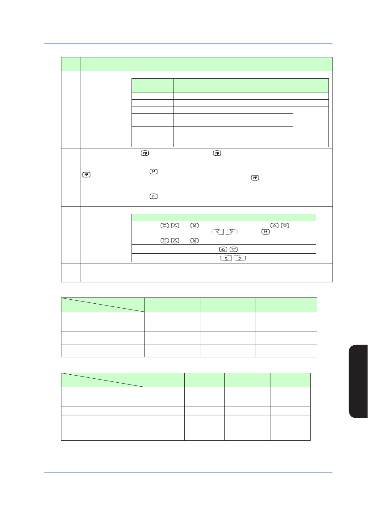
Table 5.7
No. in
Figure
(16)
(17)
(18)
(19)
Monitoring and Control of Regular Operations (Operation Display)
Name Description
The controller operation status is displayed.
Display Description
[POWER DOWN] Power down is being detected. (1)
Operation status
display
[H.MAN] Hard manual selector switch has been activated. (2)
(No indication) The instrument is operating.
[STOP] Operation stopped (such as while setting a function
on the Engineering Display, etc.)
[TEST1] Test run mode 1 (only in the programmable mode)
[TEST2]
Test run mode 2 (only in the programmable mode)
Simulation program is being executed
The key function is displayed. The key function display is different in the multi-function
mode and the programmable mode.
1) Multi-function mode
key function
display
The key function is set using the PF key function selection parameter [PFKEY].
When the STC mode selection is “not OFF” and the “ key has been set to STC”, the
function display becomes [STC]. In other cases, nothing is displayed.
2) Programmable mode
The key function can be defined in user programs.
The function display becomes [PF] in the programmable mode.
The key LOCK status is displayed.
Display Description
Key LOCK status
display
[ALLK]
[MDLK]
[SVLK]
[MVLK]
, , and keys, SV increase and decrease ( , ) keys, MV
increase and decrease ( , ) keys, and key are disabled.
, , and keys are disabled.
SV increase and decrease (
MV increase and decrease (
Control status is displayed in abbreviations. Control status display differs according to
Control status display
the controller mode in the multi-function mode; or according to the control module in the
programmable mode. See Tables 5.8 to 5.10.
Display
Priority Order
(3)
, ) keys are disabled.
, ) keys are disabled.
Table 5.8 Control Status Display in the YS1500/YS1700 Multi-function Mode
Controller Mode
Display Item
Control status display (Note 1)
Control substatus display 1 (Note 2)
Control substatus display 2 (Note 3)
Table 5.9 Control Status Display in the YS1700 Programmable Mode
Control Module
Display Item
Control status display (Note 1)
Control substatus display 1 (Note 2)
Single Loop Cascade Selector
CAS
SPC, DDC
BUA, BUM
EXT-MAN,EXT-AUT
EXT-PMV,EXT-TRK
SV TRK, PV TRK OPEN, CLOSE
Basic Control
CAS
SPC, DDC
BUA, BUM
CAS
SPC, DDC
BUA, BUM
None None
Cascade
Control
CAS
SPC, DDC
BUA, BUM
Selector Control
CAS
SPC, DDC
BUA, BUM
CAS
SPC, DDC
BUA, BUM
SV2-RMT, SV2-LCL
SEL1, SEL2
Dual-loop
CAS
SPC, DDC
BUA, BUM
None None None None
Control
SV2-RMT
Control substatus display 2 (Note 3)
None OPEN, CLOSE
SV2-LCL
SEL1, SEL2, SEL-
None
EXT
Note 1: Only when the operation mode is in cascade setting automatic control (C mode) is a control status displayed, while nothing is indicated in
automatic control (A mode) or manual control (M mode).
Note 2: When each control substatus is generated, one item is displayed. Nothing is displayed when a status is not generated.
Note 3: One of the control substatuses is always displayed.
Monitoring and Control of
Regular Operations
IM 01B08B02-01EN
21
Page 25
Monitoring and Control of Regular Operations (Operation Display)
Table 5.10 Meaning of Display Abbreviations
Symbol Meaning Symbol Meaning
CAS
SPC
DDC
BUA
BUM
EXT-MAN
EXT-AUT
EXT-PMV
EXT-TRK
► Forcausesofalarmsthathaveoccurredandactionstobetaken:see“Troubleshooting”inthismanual.
Remote operation being conducted in response to
external setpoint input
Remote operation being conducted in response to
SV from a high-level device
Remote operation being conducted in response to
MV from a high-level device
Transition to backup auto status
Transition to backup manual status
Transition to manual control in response to external
digital input
Transition to automatic control in response to
external digital input
Preset MV being output in response to external
digital input
Output being tracked in response to external digital
input
SV TRK
PV TRK
OPEN
CLOSE
SV2-RMT
SV2-LCL
SEL1
SEL2
SEL-EXT
Operating the METER Display
The following four operations can be conducted on the METER Display.
(1) Operation mode switching operation
(2) SV setting operation
(3) MV operation
(4) key operation
SV being tracked
PV being tracked
(Internal) cascade open
(Internal) cascade closed
Loop 2’s SV2 remote setting
Loop 2’s SV2 local setting
Loop 1 side’s selection status
Loop 2 side’s selection status
External signal selection status
The operations can be conducted in the loop 1 when the display title shows METER 1, and in the loop 2 when it shows METER 2.
The operation methods are the same as those of the LOOP Display.
22
IM 01B08B02-01EN
Page 26

Monitoring and Control of Regular Operations (Operation Display)
Intentionally blank
IM 01B08B02-01EN
Monitoring and Control of
Regular Operations
23
Page 27
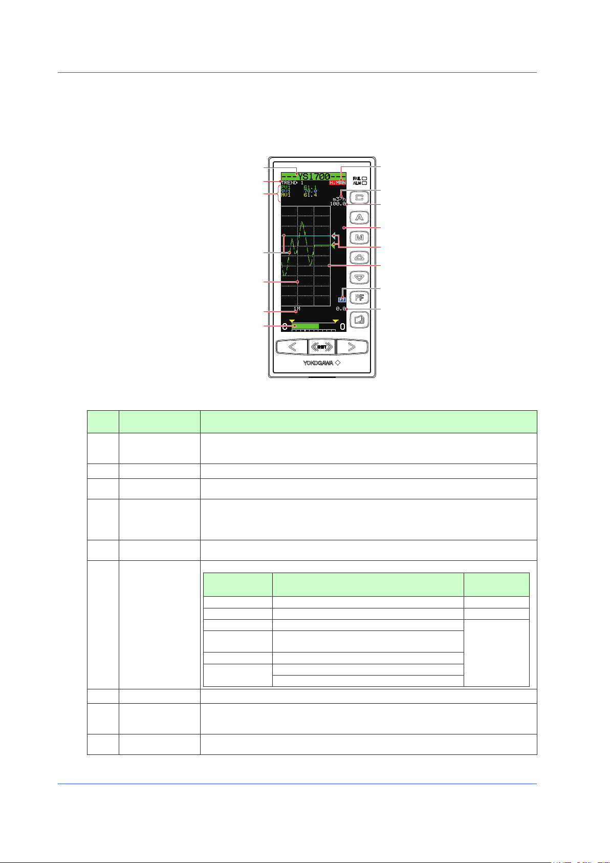
Monitoring and Control of Regular Operations (Operation Display)
(5) Trend data 1 to 4 pointers
(14) Key LOCK status display
(13) PF key function display
(8) 0% value of scale
Tag number (1)
Display title (2)
Time span scale (10)
Trend display time span (11)
MV display (12)
(6) Operation status display
(7) Engineering units
(8) 100% value of scale
(9) Scale marks
Trend data 1 to 4 trend display (4)
Trend data 1 to 4 digital display (3)
0503E.ai
Monitoring and Operating the TREND Display
The TREND Display provides trend displays of PV, SV, MV, etc. in addition to the LOOP Display functions.
The TREND 1 Display can provide trend displays of PV1, SV1, and MV1; the TREND 2 Display can provide those of PV2, SV2,
andMV2;andtheTREND3DisplaycanshowthoseofanyfourdataselectedfromPV1,PV2,SV1,SV2,MV1,MV2,X1,X2,
X3,X4,X5,X6,X7,X8,Y1,Y2,Y3,andY4.TRENDDisplayalsoenablesdisplaydatatobeturnedON/OFF.Itdoesnotdisplay
control statuses and alarms that have occurred.
Table 5.11
No. in
Figure
(1) Tag number
(2) Display title The title of the display being shown is indicated.
(3) Digital display
(4) Trend display
(5) Trend data pointers
(6)
(7) Engineering units Engineering units (UNIT) are displayed in a maximum of seven digits.
(8)
(9) Scale marks
Figure 5.3
Name Description
A tag number combining alphanumeric characters and symbols having a maximum of 12 digits
is displayed on a loop basis.
For TREND 3 Display, the tag number of the loop 1 is indicated.
PV, SV, and MV digital values are displayed.
For TREND 3 Display, data selections 1 to 4 are indicated.
The time span of the set trend display is divided into 60 partitions, and PV, SV and MV values
in the period of one time partition are displayed with the smallest and largest values of selected
data in the vertical line of one element. Trend display is clipped and displayed at 0% if a
relevant value is below 0% or at 100% if it exceeds 100%.
PV, SV, and MV values and selected data are indicated with triangular pointers. The pointer
display moves up and down with a resolution of 0.5%.
The controller operation status is displayed.
Display Description
[POWER DOWN] Power down is being detected. (1)
Operation status
display
0% value of scale,
100% value of scale
[H.MAN] Hard manual selector switch has been activated. (2)
(No indication) The instrument is operating.
[STOP] Operation stopped (such as while setting a function
[TEST1] Test run mode 1 (only in the programmable mode)
[TEST2]
on the Engineering Display, etc.)
Test run mode 2 (only in the programmable mode)
Simulation program is being executed
The 0% value of scale (SCL) and the 100% value of scale (SCH) of PV and SV are displayed
on a loop basis in digital values of five significant digits (seven digits including a sign and
decimal point).
A scale divided into a maximum of 10 divisions (10% segments) is displayed. Moreover,
horizontal lines corresponding to the scale marks are indicated in dotted lines.
Display
Priority Order
(3)
24
IM 01B08B02-01EN
Page 28
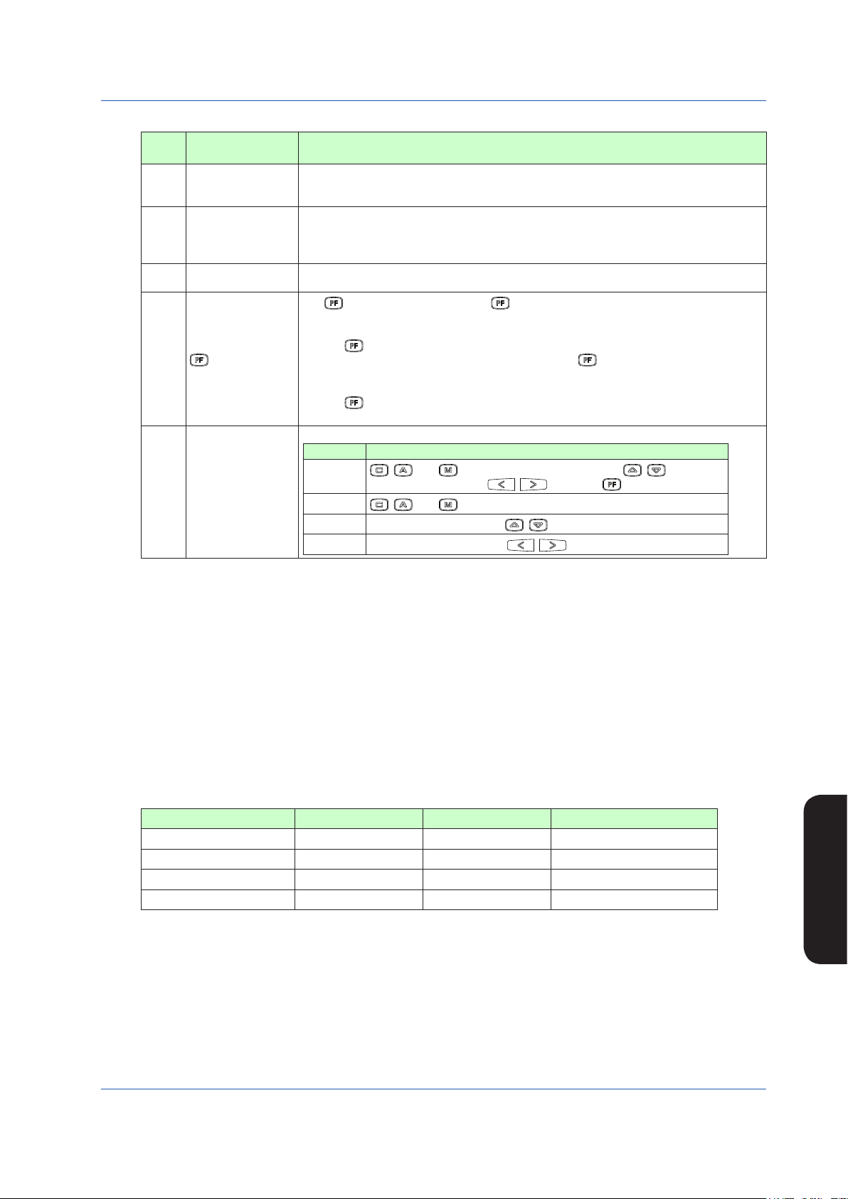
Table 5.12
No. in
Figure
(10)
(11)
(12)
(13)
(14)
Monitoring and Control of Regular Operations (Operation Display)
Name Description
The time span scale (a vertical line) is displayed by a dotted line at the 60-line positions. If the
Time span scale
Trend display time
span
MV display
key function display
Key LOCK status display
scale marks are divided into 4 divisions or more, the time span scale is also displayed at the
30-line positions.
The trend display time span setpoint is displayed. The trend display span is 90 lines, but it
represents the time span for 60 lines. Trend display is provided such that the 0-line position
is the current time, while the 90-line position is the maximum past time. Changing the trend
display time span causes data that has been displayed up to that time to be cleared.
The MV bar, MV scale, MH pointer, ML pointer, MV underflow, MV overflow, and MV valve
direction are displayed. The display contents are the same as those of the LOOP Display.
The key function is displayed. The key function display is different in the multi-function
mode and the programmable mode.
1) Multi-function mode
The key function is set using the PF key function selection parameter [PFKEY].
When the STC mode selection is “not OFF” and the “ key has been set to STC”, the
function display becomes [STC]. In other cases, nothing is displayed.
2) Programmable mode
The key function can be defined in user programs.
The function display becomes [PF] in the programmable mode.
The key LOCK status is displayed.
Display Description
[ALLK]
[MDLK]
[SVLK]
[MVLK]
, , and keys, SV increase and decrease ( , ) keys, MV
increase and decrease ( , ) keys, and key are disabled.
, , and keys are disabled.
SV increase and decrease (
MV increase and decrease (
, ) keys are disabled.
, ) keys are disabled.
Operating the TREND Displays
The following operations can be conducted on the TREND 1 and TREND 2 Displays:
(1) Operation mode switching of the loop displayed
(2) SV setting operation of the loop displayed
(3) MV operation of the loop displayed
(4) PF key operation
The following operations can be conducted on the TREND 3 Display:
(1) MV1 operation
(2) PF key operation
The operation methods are the same as those of the LOOP Display.
The following table shows the contents displayed in trend data 1 to 4.
TREND 1 Display TREND 2 Display TREND 3 Display
Trend data 1
Trend data 2
Trend data 3
Trend data 4 None None Set using the TRDS4 parameter
Note: When the controller mode is set to the cascade/selector mode, MV will be displayed.
PV1 PV2
SV1 SV2
MV1 (Note) MV2 (Note)
Set using the TRDS1 parameter
Set using the TRDS2 parameter
Set using the TRDS3 parameter
Monitoring and Control of
Regular Operations
IM 01B08B02-01EN
25
Page 29
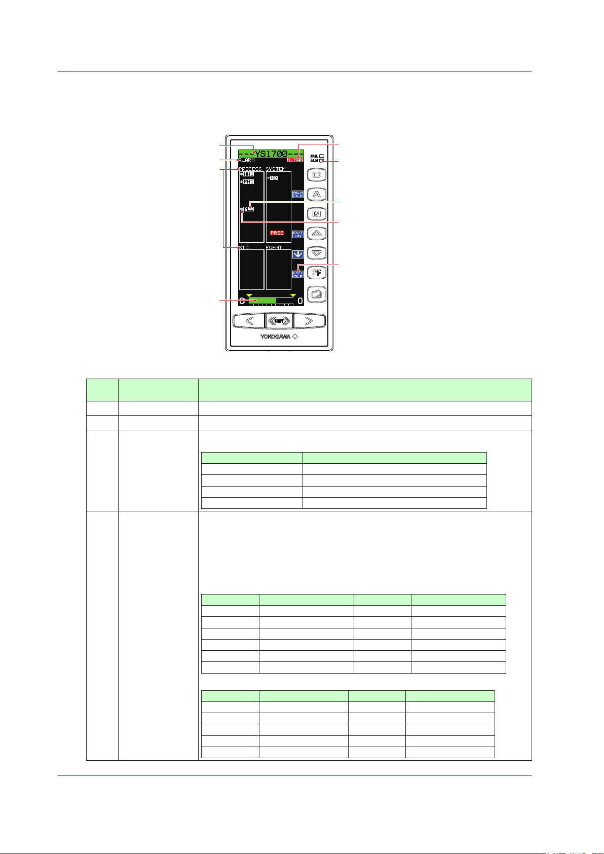
Monitoring and Control of Regular Operations (Operation Display)
0504E.ai
Monitoring and Operating the ALARM Display
The ALARM Display collectively indicates detailed information when alarm(s) occurs. It allows the user to acknowledge unacknowledged alarms and events.
Table 5.13
No. in
Figure
(1)
(2)
(3)
(4)
Tag number (1)
Display title (2)
Item title (3)
MV display (9)
Figure 5.4
(6) Operation status display
(7) Alarm lamp
(4) Alam item
(5) Unacknowledged alarm marks
(8) Software key function display
Name Description
Tag number The tag number of the loop 1 is displayed.
Display title The title of the display being shown is indicated.
Alarms and events that have occurred or been generated are displayed on a type basis. They
are classified into the following four types:
Display Description
Item title
[PROCESS] Process alarms
[STC] STC alarms
[SYSTEM] System alarms
[EVENT] Event display
There are two types of display formats for alarm items as follows:
Red backlit display of items: An alarm(s) is currently being generated
Normal display of items: Indicates that an alarm(s) was generated in the past, but the situation
has now recovered
► Forcausesofalarmsthathaveoccurredandactionstobetaken:see“Troubleshooting”in
this manual.
The alarm items to be displayed are as follows:
Process Alarms
Display Description Display Description
[PH1] PV1 high limit alarm [PH2] PV2 high limit alarm
[PL1] PV1 low limit alarm [PL2] PV2 low limit alarm
Alarm item
[HH1] PV1 high-high limit alarm [HH2] PV2 high-high limit alarm
[LL1] PV1 low-low limit alarm [LL2] PV2 low-low limit alarm
[DL1] Deviation 1 alarm [DL2] Deviation 2 alarm
[VL1] PV1 velocity alarm [VL2] PV2 velocity alarm
STC Alarms
Display Description Display Description
[SYS-ALM] System alarm [PWRDWN] Power supply failure
[PVOVR] PV alarm [PBLMT] PB alarm
[MVLMT] MV alarm [TILMT] TI alarm
[OPERR] Operation failure [TDLMT] TD alarm
[IDERR] Identification impossible [RTALM] RT alarm
26
IM 01B08B02-01EN
Page 30

Table 5.14
No. in
Figure
(4)
Alarm item
Unacknowledged
(5)
alarm marks
Operation status
(6)
display
(7)
Alarm lamp Lights up if a process alarm, STC alarm, or system alarm occurs.
Software key function
(8)
display
(9) MV display
Monitoring and Control of Regular Operations (Operation Display)
Name Description
System Alarms
Display Description
[X1]to[X8] InputoverrangeRegisternamesX1toX8thathavebeenallocated
to each input terminal are displayed.
[Y1] and [Y3]
Output open (current output only) Register names Y1 and Y3 are displayed.
[CALC] Computation overflow (only in the YS1700 programmable mode)
[OVER]
Exceeding of control period (only in the YS1700 programmable mode)
[COMM] RS-485 communication error, DCS-LCS communication error, or
peer-to-peer communication error
[ETHER] Ethernet communication error
[PTOP] Peer-to-peer communication error
[PROG] User program error
[DATA] YSS1000 writing incomplete
[CALR] Adjustment inspection error
Event indication
Display Description
[EVENT1] to
User-set events 1 to 5
[EVENT5]
For unacknowledged alarms, [*] is indicated in front of alarm items.
The controller operation status is displayed.
Display Description
[POWER DOWN] Power down is being detected. (1)
[H.MAN] Hard manual selector switch has been activated. (2)
(No indication) The instrument is operating.
[STOP] Operation stopped (such as while setting a function
on the Engineering Display, etc.)
[TEST1] Test run mode 1 (only in the programmable mode)
[TEST2]
Test run mode 2 (only in the programmable mode)
Simulation program is being executed
Indicates that the [ALM CLR] software key is allocated to the key, the [EVT ON] software key to
the key,the[↓]softwarekeytothe key, and the [EVT CLR] software key to the key.
► Foroperation:seethefollowing“OperatingtheALARMDisplay.”
MV bar, MV scale, MH pointer, ML pointer, MV underflow, MV overflow, and MV valve direction
are displayed. The display contents are the same as those of the LOOP Display.
Display
Priority Order
(3)
Operating the ALARM Display
The following operations can be conducted on the ALARM Display:
(1) MV operation (the same as that of the LOOP Display)
(2) Acknowledgement of unacknowledged alarms/events
(3) Re-display of event indication
● Acknowledgingunacknowledgedalarms/events
The Alarm [ALM CLR] software key is used to acknowledge that an alarm has occurred. When this key is pressed, the “*” mark that indicates that the alarm concerned
has not yet been acknowledged, and that indicates currently not occurring alarms will be erased, implying that the alarm(s) has been acknowledged.
The Event [EVT CLR] software key is used to acknowledge an event. When this key is pressed, the “*” mark that indicates that the event concerned has not yet been
acknowledged, and that indicates events currently not generated will be erased, implying that the event(s) has been acknowledged.
● Re-displayingeventindication
Browsethroughtheeventlinesusingthe[↓]softwarekey( key) to select an event you wish to see and then press the [EVT
ON] software key ( key). This causes the event to be re-displayed.
Select a generated event using the [↓] software key ( key) then
Select an event.
*
C
IM 01B08B02-01EN
press the [EVT ON] software key ( key). This causes the
generated event status (*) to be displayed.
Press the [EVT CLR] software key ( key), and then clears the
selected generated event status (*).
0505E.ai
Figure 5.5
Monitoring and Control of
Regular Operations
27
Page 31

Monitoring and Control of Regular Operations (Operation Display)
0506E.ai
Monitoring and Operating the DUAL Display
The DUAL Display has two display titles: DUAL1 and DUAL2.
Information concerning PV, SV, and MV are displayed simultaneously for both loops. The loop 1 information is shown on the left,
and the loop 2 information is displayed on the right.
(12) Operation status display
(7) Engineering units
(8) 100% value of scale
(16) Key LOCK status display
(11) PV overflow
(10) SV pointer
(9) PV bar scale
(15) PF key function display
(8) 0% value of scale
Table 5.15
No. in
Figure
(1) Tag number
Tag number (1)
PV, SV, MV digital display
(Inverse display: Operable loop)
HH pointer, PH pointer (13)
LL pointer, PL pointer (13)
Display title (2)
(3)
Loop number (4)
Control substatus (5)
PV bar (6)
PV undreflow (11)
MV display (14)
Figure 5.6
Name Description
The tag number of the loop 1 appears for DUAL1 Display, while that of the loop 2 appears for
DUAL2 Display.
(2) Display title The title of the display being shown is indicated.
PV, SV, and MV
(3)
digital display
PV, SV, and MV digital values of the loop 1 are displayed at the left and those of the loop 2 at
the right. The loop that is inverse displayed can be operated.
(4) Loop number Loop numbers “1” (left) and “2” (right) are displayed.
Control substatus is inverse displayed in one character below the loop number. The substatus
(5) Control substatus
display shown in Table 5.17 is indicated depending on controller mode in the multi-function mode or
a control module in the programmable mode. Nothing is indicated in cases other than this.
(6) PV bar
(7) Engineering units
0% value of scale,
(8)
100% value of scale
PV1 (left) and PV2 (right) are displayed in bars. The bar display is in 200 dots at full scale
(100%) and increases or decreases on a dot (0.5%) basis.
Engineering unit 1 (left) and engineering unit 2 (right) are displayed in a maximum of seven digits.
SCL1, SCH1 (left), SCL2, and SCH2 (right) are displayed in engineering units in digital values
of five significant digits (seven digits including a sign and decimal point).
(9) PV bar scale The PV bar scale is displayed divided into a maximum of 10 divisions (10% segments).
(10) SV pointer
PV underflow,
(11)
PV overflow
SV1 (left) and SV2 (right) are indicated with triangular pointers. The pointer display moves up
and down with a resolution of 0.5%.
PV underflow (PV1 at the left, PV2 at the right) is displayed if a PV value is below 0%, while PV
overflow (PV1 at the left, PV2 at the right) is displayed if it exceeds 100%.
The controller operation status is displayed.
Display Description
Priority Order
[POWER DOWN] Power down is being detected. (1)
[H.MAN] Hard manual selector switch has been activated. (2)
(No indication) The instrument is operating.
[STOP] Operation stopped (such as while setting a
(12)
Operation status
display
function on the Engineering Display, etc.)
PH, PL, HH, and LL
(13)
pointers
[TEST1]
[TEST2]
PH values (high limit alarm setpoints for PV) and PL values (low limit alarm setpoints for PV) are indicated
with triangular pointers, while HH values (high-high limit alarm setpoints for PV) and LL values (low-low
limit alarm setpoints for PV) are indicated with pointers which are overlapped pairs of triangles.
Test run mode 1 (only in the programmable mode)
Test run mode 2 (only in the programmable mode)
Simulation program is being executed
Display
(3)
28
IM 01B08B02-01EN
Page 32

Monitoring and Control of Regular Operations (Operation Display)
Table 5.16
No. in
Figure
(14) MV display
Name Description
The MV bar, MV scale, MH pointer, ML pointer, MV underflow, MV overflow, and MV valve
direction are displayed. The display contents are the same as those of the LOOP Display.
The key function is displayed. The key function display is different in the multi-function
mode and the programmable mode.
1) Multi-function mode
(15)
key function
display
The key function is set using the PF key function selection parameter [PFKEY].
When the STC mode selection is “not OFF” and the “ key has been set to STC”, the
function display becomes [STC]. In other cases, nothing is displayed.
2) Programmable mode
The key function can be defined in user programs.
The function display becomes [PF] in the programmable mode.
The key LOCK status is displayed.
Display Description
[ALLK]
Key LOCK status
(16)
display
[MDLK]
[SVLK]
[MVLK]
Table 5.17
Controller Mode or
Control Module
Cascade or CSC control
module
Selector or SSC control
module
► Controlmodule:YSS1000SettingSoftware/YS1700ProgrammableFunctionUser’sManual
Control Substatus
Display in DUAL Display
O The cascade is open. OPEN
S
E
, , and keys, SV increase and decrease ( , ) keys, MV
increase and decrease ( , ) keys, and key are disabled.
, , and keys are disabled.
SV increase and decrease (
MV increase and decrease (
, ) keys are disabled.
, ) keys are disabled.
Description Control Substatus Display in LOOP
The corresponding loop
has been selected.
An external signal has
been selected.
Display
SEL1 (where “S” is displayed in the loop1) or
SEL2 (where “S” is displayed in the loop2)
EXT(intheprogrammablemode)
Operating the DUAL Display
The following four operations can be conducted on the DUAL Display:
(1) Operation mode switching operation
(2) SV setting operation
(3) MV operation
(4) key operation
The operation methods are the same as those of the LOOP Display.
When the display title is DUAL1, the loop 1 can be operated; when it is DUAL2, the loop 2 can be operated. To make the operable
loop easy to identify, the color of the backlit tag number, PV bar, and MV bar on the operable loop are displayed in the same color
(selected loop color).
Monitoring and Control of
Regular Operations
IM 01B08B02-01EN
29
Page 33

Monitoring and Control of Regular Operations (Operation Display)
0506-01E.ai
0507E.ai
displayed on the control status display section.
Switching of Operation Modes (Automatic Control (A), Manual Control (M), or Cascade Setting
Automatic Control (C))
Switching by Keystroke
The operation mode can be switched by pressing the relevant key in the table below. This causes the
light inside the key corresponding to the selected operation mode to light up. Note that on the ALARM
Display, the operation mode cannot be switched.
Key Name Function
Press this key to change to manual operation.
M mode key
A mode key Press this key to change to automatic control.
C mode key
It is not possible to change from manual control to cascade
setting automatic control. To change to cascade setting
automatic control, do so via automatic control.
Press this key to change to automatic control to set a value
from an external analog signal or communication as a
cascade setting.
(The C mode key is disabled when shipped from the
factory.)
Note
If the operation mode switching function is allocated to digital input, there may be
cases where the operation mode cannot be switched by keystrokes. In such cases,
check the allocation of the digital input function.
Operation mode transition in the figure below represents the single-loop mode with analog input-based cascade setting. If cascade setting is not used, it is only possible to switch between automatic control and manual control.
► Foroperationmodetransition:see1.1,SelectingtheControllerMode(CTL),intheYS1500IndicatingController/YS1700ProgrammableIndi-
cating Controller User’s Manual.
Cascade setting automatic control
Automatic
control
A
C
(C)
(CAS)
A
(A)
C
M
M
A: Automatic control
M: Manual control
C, CAS: Cascade setting automatic control
Manual control
When the operation mode is in cascade
setting automatic control, [CSV] is
A
(M)
C
M
Figure 5.7
A
: Press the A mode key.
: Press the M mode key.
M
C
: Press the C mode key.
30
IM 01B08B02-01EN
Page 34

Monitoring and Control of Regular Operations (Operation Display)
Cascade mode (no cascade setting based on analog input) Selector mode (no cascade setting based on analog input)
0508E.ai
Switching in Response to Digital Input
No function is allocated to digital input when shipped from the factory. To switch the operation mode in response to digital input,
the operation mode switching function needs to be allocated to digital input.
► Fordigitalinputfunctionassignment:seeChapter3,AuxiliaryInputandOutputFunctions,intheYS1500IndicatingController/YS1700Program-
mable Indicating Controller User’s Manual.
Operation mode transition in the figure below represents the cascade and selector modes. There is no cascade setting based on
analog input.
► Foroperationmodetransition:see1.1,SelectingtheControllerMode(CTL),intheYS1500IndicatingController/YS1700ProgrammableIndi-
cating Controller User’s Manual.
Loop 1
status
Loop 2
status
A
C
A
2
1
M
(C) (C)
CLOSE
A1-C2
(CLOSE)
A
2
(A) (A)
OPEN
A1-A2
(OPEN)
M
M
2
1
(M)
2
M
1
C
2
A
1
A
2
M
1
C
2
CLOSE
(M)(A) (M)(A)
A
1
M1-M2
(CLOSE)
A
2
M
2
Loop 1
Loop 2
status
SV2-RMT
SV2-LCL
(M)
SV2-RMT
status
A
1
A
2
A1-A2
(SV2-LCL)
M
M
2
1
A
A
1
2
M1-M2
(M)
(OPEN)
OPEN
M
C
C
M
2
2
1
1
* Pressing the C mode key in the loop 1 does not change the operation
mode.
* The heavy lines indicate that the open/closed status has changed.
An: Automatic control, Mn: Manual control,
A1-C2
(CLOSE)
Cn: (Internal) Cascade control (n: “1” stands for
loop 1 and “2” indicates loop 2.)
CLOSE/OPEN: Cascade closed/cascade open
This is displayed on the control status display section.
M
: Press the M mode key in the loop 1 (the number represents the relevant loop)
1
A
: Press the A mode key in the loop 2 (the number represents the relevant loop)
2
IM 01B08B02-01EN
A
A
1
2
(M)
(SV2-LCL)
SV2-LCL
* Pressing the C mode key in the loop 1 or loop 2 does not change
the operation mode.
An: Automatic control, Mn: Manual control
A1-A2
(SV2-LCL)
Figure 5.8
(n: “1” stands for loop 1 and “2” indicates
loop 2.)
SV2-LCL: Loop2 is in local.
This is displayed on the control
status display section.
M1-M2
M
1
M
2
Monitoring and Control of
Regular Operations
31
Page 35

Operating the Tuning Displays
0601E.ai
There are displays for setting and displaying control parameters such as PID, etc. and a display for monitoring input/output signals. To set tuning parameters proceed according to the setting examples below, and refer to “Overview of Display Switching and
Operation Keys” and “List of Parameters”.
► Fordisplayingandsettingparameters:see“ListofParameters”inthismanual.
► Foradescriptionoftuningparameterfunctions:seeYS1500IndicatingController/YS1700ProgrammableIndicatingControllerUser’sManual.
Note
YS1000 has a password function as a security function. If the password has been set up, enter it and then change
parameters.
► Forsettingandcancelingpasswords:see4.2.2,Inhibiting/EnablingParameterChange,intheYS1500IndicatingController/YS1700Program-
mable Indicating Controller User’s Manual.
Setting PID
Setting Display
Tuning Display
Operation Display >
(PID Setting Display 1) or [PID2] software key (PID Setting Display 2)
Setpoint changing procedure (example of changing proportional band 1):
(1) Pressthe[↓]softwarekeytoselectandzoominonproportionalband1[PB1
999.9%].
(2) Press the [ ] or [ ] software key to change the setpoint. Holding it down
accelerates the value increase/decrease speed.
(3) Press the Page key to return to the Tuning Menu Display.
(4) Press the SHIFT + Page keys twice to return to the Operation Display.
SHIFT
+ keys (to the Tuning Menu Display) > [PID1] software key
This completes the setting procedure.
Setting Details
Parameters Names Setting Range Factory Default
PB1, PB2 Proportional band 0.1 to 999.9 (%) 999.9
TI1, TI2 Integral time 1 to 9999 (s) 1000
TD1, TD2 Derivative time 0 to 9999 (0: no action) 0
Description
The PB2, TI2, and TD2 parameters are used in the loop 2 in the cascade mode, selector mode, and programmable mode.
► Forproportionalband,integraltime,andderivativetime:see“TuningGuide”inthismanual.
32
32
IM 01B08B02-01EN
Page 36

Displaying the Operation Display While the Tuning Display is being Shown
0603E.ai
Pressing the [OPE] software key while setting a tuning parameter returns you to the Operation Display.
Tuning Display
[OPE] software key
0602E.ai
Setting Alarms
Setting Display
Tuning Display
Operation Display >
(PID Setting Display 1) or [PID2] software key (PID Setting Display 2)
Setpoint changing procedure (example of changing high limit alarm setpoint for PV1)
SHIFT
+ keys (to the Tuning Menu Display) > [PID1] software key
Operating the Tuning Displays
(1) Pressthe[↓]softwarekeytoselectandzoominonhighlimitalarmsetpointforPV1
[PH1 106.3].
(2) Press the [ ] or [ ] software key to change the setpoint. Holding it down
accelerates the value increase/decrease speed.
(3) Press the Page key to return to the Tuning Menu Display.
(4) Press the SHIFT + Page keys twice to return to the Operation Display.
This completes the setting procedure.
Setting Details
Parameters Names Setting Range Factory Default
PH1, PH2 High limit alarm setpoint for PV
PL1, PL2 Low limit alarm setpoint for PV
HH1, HH2 High-high limit alarm setpoint for PV
LL1, LL2 Low-low limit alarm setpoint for PV
DL1, DL2 Deviation alarm setpoint
VL1, VL2 PV velocity alarm setpoint
VT1, VT2 PV velocity alarm time setpoint 1 to 9999 1
HYS1, HYS2 Alarm hysteresis
*1 Engineering unit set using the engineering parameters SCH1, SCL1, and SCDP1 (or SCH2, SCL2, and SCDP2).
Engineeringunitsequivalentto−6.3to106.3%
(*1)
Engineeringunitsequivalentto−6.3to106.3%
(*1)
Engineeringunitsequivalentto−6.3to106.3%
(*1)
Engineeringunitsequivalentto−6.3to106.3%
(*1)
Engineering units equivalent to 0.0 to 106.3%
(*1)
Engineering units equivalent to 0.0 to 106.3%
(*1)
Engineering units equivalent to 0.0 to 20.0%
(*1)
106.3
-6.3
106.3
-6.3
0.0
0.0
2.0
Operating the Tuning
Displays
IM 01B08B02-01EN
33
Page 37

Operating the Tuning Displays
0604E.ai
High-high limit alarm setpoint for PV
Time
0605E.ai
Deviation alarm output
Time
Description
The PH2, PL2, HH2, LL2, DL2, VL2, and VT2 parameters are used in the loop 2 in the cascade mode, selector mode, and programmable mode.
If the high limit alarm setpoint for PV and the high-high limit alarm setpoint for PV are set to the maximum values, no alarm is
generated.
If the low limit alarm setpoint for PV and the low-low limit alarm setpoint for PV are set to the minimum values, no alarm is generated.
Alarm hysteresis HYS1 acts on PH1, PL1, HH1, LL1, and DL1 collectively, while alarm hysteresis HYS2 acts on PH2, PL2, HH2,
LL2, and DL2 collectively.
The following figure shows an example of actions of the high limit alarm for PV, high-high limit alarm for PV, low limit alarm for PV,
low-low limit alarm for PV, and alarm hystereses.
High-high limit alarm output for PV
High limit alarm output for PV
Closed Open
Open Closed
Closed
High limit alarm setpoint for PV
PV
Low limit alarm setpoint for PV
Low-low limit alarm setpoint for PV
Low limit alarm output for PV
Low-low limit alarm output for PV
Alarm hysteresis (HYS)
Alarm hysteresis (HYS)
Closed Open
Closed Open
For an example in the figure above, the contact type is such that the contact
opens if an event occurs (factory default).
The following figure shows an example of actions of deviation alarms and alarm hysteresis.
Alarm hysteresis (HYS)
Alarm hysteresis (HYS)
The value of alarm hysteresis is common to the high limit alarm for PV, high-high limit alarm for PV, low limit alarm for PV, low-low
limit alarm for PV, and the deviation alarm.
34
Setpoint (SV)
Closed ClosedOpenClosed Open
Alarm hysteresis (HYS)
Deviation alarm setpoint
PV
Deviation alarm setpoint
Alarm hysteresis (HYS)
For an example in the figure above, the contact type is such that the contact opens
if an event occurs (factory default).
IM 01B08B02-01EN
Page 38

The figure below shows an example of action of velocity alarm for PV.
0606E.ai
Velocity alarm
Operating the Tuning Displays
output for PV
Closed
Open
Closed
Open
Closed
PV
Exceeds the velocityExceeds the velocity
Time
Velocity alarm
time setpoint
Velocity alarm
setpoint
An alarm occurs if the velocity
exceeds this inclination.
Velocity alarm
setpoint
Velocity alarm
time setpoint
For an example in the figure above, the contact type is such that the contact opens
if an event occurs (factory default).
The following table shows the sections to refer to for descriptions of the main functions. Consult them as they also describe functions other than those noted below.
These references are located in the YS1500 Indicating Controller/YS1700 Programmable Indicating Controller User’s Manual.
Function Reference Location
Alarm function 3.1.5, Changing Digital Output Functions
Output limiter 1.2.3, Stopping Integral Action to Conduct Control with Less Overshoot (Output Limiter)
Preset MV 2.4, Using Preset MV
Adjustable setpoint filter
function
1.2.6, Performing Stable Control for the Step Response of Setpoints (Adjustable Setpoint
Filter)
Input filter 2.1.1, Input Filter (First-order Lag Computation)
Square root extraction 2.1.2, Square Root Extraction (Low Cutoff Adjustable)
Line segment 2.1.3, 10-segment Linearizer Function
Ratio 2.1.4, Ratio Operation
IM 01B08B02-01EN
Operating the Tuning
Displays
35
Page 39

Operating the Engineering Displays
There is a display for setting up functions as a controller, a display for setting and displaying various registers and tables, the Input
Specification Setting Display, and the Password Setting Display. To set engineering parameter settings, proceed according to the
setting examples below, and refer to the “Overview of Display Switching and Operation Keys” and “List of Parameters.”
► Fordisplayingandsettingparameters:see“ListofParameters”inthismanual.
► Foradescriptionofengineeringparameterfunctions:seeYS1500IndicatingController/YS1700ProgrammableIndicatingControllerUser’s
Manual.
CAUTION
There is a SET parameter in the engineering parameters to prevent accidental changes to settings. Unless this parameter
setting is changed from INHB (setting inhibited) to ENBL (setting enabled), parameters on the same display cannot be
changed. Be aware that changing the setting to ENBL causes YS1000’s control action and input/output to be changed.
The YS1000 enters manual operation and control stopped status, causing [STOP] to appear at the upper right of the
display. The setpoints, manipulated output variables, analog output values, analog output registers, PF status, PF status
registers, temporary storage registers, output registers, and digital output registers retain the values they had immediately
prior to STOP. Dynamic computation (computation with a device number), such as first-order lag and dead time, will be
initialized. For user program data, see the YSS1000 Setting Software/YS1700 Programmable Indicating Controller User’s
Manual.
Note
YS1000 has a password function as a security function. If the password has been set up, enter it and then change
parameters.
► Forsettingandcancelingpasswords:see4.2.2,Inhibiting/EnablingParameterChange,intheYS1500IndicatingController/YS1700
Programmable Indicating Controller User’s Manual.
Note
In the programmable mode, there are three displays for the engineering menu. The menu display is switched each time the
Page key is pressed.
Setting the Controller Mode
Note
Changing the controller mode causes various parameters to be initialized. For more information, see List of Parameters (p.64). To
change the controller mode, press and hold the [ ] or [ ] software key for more than 5 seconds.
Engineering Display
Operation Display >
the Engineering Menu Display) > [CONFIG1] software key (Configuration Display 1)
Setpoint changing procedure:
(1) Pressthe[↓]softwarekeytoselectandzoominon[SETINHB].
(2) Press the [ ] software key to change to [SET ENBL].
(3) Pressthe[↓]softwarekeytoselectandzoominoncontrollermodeselection[CTL
SINGLE].
(4) Press and hold the [ ] or [ ] software key for more than 5 seconds to change the
setpoint.
(5) Press the Page key to return to the Engineering Menu Display. (The SET parameter
returns to setting inhibited [SET INHB] at the instant when you are brought to the
menu display.)
(6) Press the SHIFT + Page keys to return to the Operation Display.
This completes the setting procedure.
SHIFT
+ keys (to the Tuning Menu Display) >
SHIFT
+ keys (to
36
36
0701E.ai
IM 01B08B02-01EN
Page 40

Setting Details
Operating the Engineering Displays
Operating the Engineering
Parameters Names Setting Range Factory Default
PROG: Programmable mode (*1)
CTL Controller mode selection
SINGLE: Single-loop mode
CAS: Cascade mode
SELECT: Selector mode
*1: Only selectable for YS1700
► Forprogrammablemode:seeYSS1000SettingSoftware/YS1700ProgrammableFunctionUser’sManual.
► Forsingle-loopmode,cascademode,andselectormode:see1.1,SelectingtheControllerMode,intheYS1500IndicatingController/YS1700
Programmable Indicating Controller User’s Manual.
For YS1700: PROG
For YS1500: SINGLE
Setting the Control Type and Control Operation Formula
Setting Display
Engineering Display
Operation Display >
the Engineering Menu Display) > [CONFIG2] software key (Configuration Display 2)
Setpoint changing procedure (example of changing control type):
(1) Pressthe[↓]softwarekeytoselectandzoominon[SETINHB].
(2) Press the [ ] software key to change to [SET ENBL].
(3) Pressthe[↓]softwarekeytoselectandzoominoncontroltype1[CNT1PID].
(4) Press the [ ] or [ ] software key to change the setpoint.
(5) Press the Page key to return to the Engineering Menu Display.
(6) Press the SHIFT + Page keys to return to the Operation Display.
A control operation formula can also be changed in the same way as above.
This completes the setting procedure.
SHIFT
+ keys (to the Tuning Menu Display) >
SHIFT
+ keys (to
Displays
0702E.ai
Setting Details
Parameters Names Setting Range Factory Default
PID: Standard PID control
CNT1, CNT2 Control type
S-PI: Sample-and-hold PI control
BATCH: Batch PID control (*1)
PID
PD: Proportional (PD) control
I-PD: PV proportional type PID
ALG1, ALG2 Control operation formula
PI-D: PV derivative type PID
I-PD
SVF: Adjustable setpoint filter
*1: Only selectable for YS1700
Description
The CNT2 and ALG2 parameters are used in the loop 2 in the cascade mode, selector mode, and programmable mode.
Single-loopMode
Standard PID control
Proportional(PD)control
Sample-and-hold PI control
Batch PID control
Legend : Available, –: Not available
► ForstandardPIDcontrol,proportionalcontrol,sample-and-holdPIcontrol,andbatchPIDcontrol:see1.2,SelectingtheControlMethod(Select-
ing Control Type CNT and Control Operation Formula ALG, in the YS1500 Indicating Controller/YS1700 Programmable Indicating Controller
User’s Manual.
Cascade Mode Selector Mode
Loop 1 Loop 2 Loop 1 Loop 2
– – – –
– –
– – – –
IM 01B08B02-01EN
37
Page 41

Operating the Engineering Displays
0704E.ai
Setting the Scale and Decimal Point Position for Process Variables
Setting Display
Engineering Display
0703E.ai
Operation Display >
the Engineering Menu Display) > [CONFIG2] software key (Configuration Display 2)
Setpoint changing procedure (example of changing scale):
(1) Pressthe[↓]softwarekeytoselectandzoominon[SETINHB].
(2) Press the [ ] software key to change to [SET ENBL].
(3) Pressthe[↓]softwarekeytoselectandzoominonthe100%valueofscale1[SCH1
1000].
(4) Press the [ ] or [ ] software key to change the setpoint. Holding it down
accelerates the value increase/decrease speed.
(5) Pressthe[↓]softwarekeytoselectandzoominonthe0%valueofscale1[SCL10].
(6) Press the [ ] or [ ] software key to change the setpoint. Holding it down
accelerates the value increase/decrease speed.
(7) Pressthe[↓]softwarekeytoselectandzoominondecimalpointposition1[SCDP1
####.#].
(8) Press the [ ] or [ ] software key to change the setpoint.
(9) Press the Page key to return to the Engineering Menu Display.
(10) Press the SHIFT + Page keys to return to the Operation Display.
Change the loop 2 in the same way as above as necessary.
This completes the setting procedure.
SHIFT
+ keys (to the Tuning Menu Display) >
SHIFT
+ keys (to
Setting Details
Parameters Names Setting Range Factory Default
SCH1, SCH2 100% value of scale −80000to80000 1000
SCL1, SCL2 0% value of scale −80000to80000 0
SCDP1, SCDP2 Decimal point position # # # # #, # # # # . #, # # # . # #, # # . # # #, # . # # # # # # # # . #
Description
The SCH2, SCL2, and SCDP2 parameters are used in the loop 2 in the cascade mode, selector mode, and programmable mode.
The figure below shows an example of setting the 100% value of scale to 1000, the 0% value of scale to 0, and the decimal point
position to one decimal place (####.#). Process variables and setpoints are displayed on the scale that is set here.
Note: If a wide scale span (100% to 0% value of
scale) is specified, the value less than 0.1%
of PV may fluctuate.
100% value of scale
0% value of scale
38
Figure 7.1
IM 01B08B02-01EN
Page 42

Registering a Tag and Units
0705E.ai
Operating the Engineering Displays
Operating the Engineering
Setting Display
Engineering Display
Setting Details
Operation Display >
SHIFT
+ keys (to the Tuning Menu Display) >
SHIFT
+ keys (to
the Engineering Menu Display) > [CONFIG2] software key (Configuration Display 2)
Setpoint changing procedure (example of setting a tag):
(1) Pressthe[↓]softwarekeytoselectandzoominon[SETINHB].
(2) Press the [ ] software key to change to [SET ENBL].
(3) Pressthe[↓]softwarekeytoselectandzoominontagnumber1[TAG1---YS1700---].
(4) Pressthe[↓]or[↑]softwarekeytomovethecursoroverthepositionwherethetagis
registered.
(5) Press the [ ] or [ ] software key to change the character (setting is made on a
character basis).
(6) Repeat steps (4) and (5) to register the tag.
(To erase a character, enter a space.)
(7) Press the Page key to return to the Engineering Menu Display.
(8) Press the SHIFT + Page keys to return to the Operation Display.
This completes the setting procedure.
Displays
Parameters Names Setting Range Factory Default
TAG1, TAG2 Tag number 12 digits of alphanumeric characters
For YS1700: ---YS1700--For YS1500: ---YS1500---
UNIT1, UNIT2 Engineering units 7 digits of alphanumeric characters %
Description
The TAG2 and UNIT2 parameters are used in the loop 2 in the cascade mode, selector mode, and programmable mode.
The tag is displayed in the top line of the LCD.
The settable ASCII codes are as shown below:
Space ! “ # $ % & ’ ( ) * + , . / 0 1 2 3 4 5 6 7 9 : ; < =
> ? @ A B C D E F G H I J K L
M N O P Q R S T U V W X Y Z [
¥ ] ^ _ ` a b c d e f g h i j
k l m n o p q r s t u v w x y
z { ¦ } ~
IM 01B08B02-01EN
39
Page 43

Tuning Guide
0801E.ai
Operation mode keys
0802E.ai
0803E.ai
This chapter describes how to activate the control functions and perform tuning for novice users.
Starting Operations by Manual Operation
The following describes how to start operations, using an example of simple PID control.
(1) Manual operation using the MV operation keys
1. Press the mode key to switch the operation mode to the M mode. This causes the LED indicator inside the mode
key to light up.
2. Press the
3. Press the
Pressing an MV operation key with the
decrease speed.
While confirming that a smooth response is obtained by manual operation, balance the PV value with the SV value or a point in its
vicinity.
or key of an SV setting key, to set the SV value.
or key of an MV operation key, to adjust the output signal.
SHIFT
(fast-change key/SHIFT key) held down accelerates the MV-value increase/
SV setting keys
MV operation keys
Figure 8.1 Switching the Operation Mode
Figure 8.2 Manual Output Operation
(2) Switching from manual operation to automatic operation
Press the mode key in condition 3. in item (1) to switch the operation mode to automatic control (A). This causes the LED
indicator inside the mode key to light up, activating automatic operation. Operation changes to automatic operation in a
bumpless(*) manner, not requiring balance operation at switching.
* Bumpless: This feature has the effect of preventing rapid output changes when automatic operation is started from an
output value obtained during manual operation.
(3) Alarm check
If the ALM lamp on the front panel is lit, there is some kind of signal abnormality. In this case, check for an alarm item on the
ALARM Display to determine the cause of the abnormality and take appropriate actions.
If the FAIL lamp is lit, an abnormality has occurred in the instrument.
► Forcausesofalarmsthathaveoccurredandactionstobetaken:see“Troubleshooting”inthismanual.
FAIL lamp (red)
ALM lamp (yellow)
40
40
Figure 8.3 ALM Lamp and FAIL Lamp
IM 01B08B02-01EN
Page 44

Tuning Guide
In auto-tuning (AT)
ON/OFF control
PID control based on
PID constants obtained
as a result of AT
Process variable
ON
OFF
0806E.ai
Time
Setpoint
Manipulated
output variable
0804E.ai
For a small proportional band
Target
setpoint
* If the proportional band is small, the PV becomes vibrational.
Offset
Time
For a larger proportional band
For an intermediate proportional band
Temperature
0805E.ai
Target
setpoint
* If the integral time is too short,
long cyclic vibration occurs in the PV.
Time
Temperature
PID Parameter Tuning Guide and Automatic Adjustment
If the indicating controller is used for an unknown process, it is important to examine the conditions carefully in which the controller is
operated by manual adjustment because they are useful in determining the proportional band (PBn), integral time (Tn), and derivative
time (TDn) when entering automatic adjustment. (n = 1, 2)
For example, if the process variable (PV) changes significantly when the controller’s manipulated output variable (MV) is simply
changed slightly, the proportional band (PBn) needs to be widened as a safety provision. In a case where the opposite conditions
prevail, the proportional band needs to be narrowed.
Moreover, for processes wherein the time required to follow a change in the controller’s output is short, the integral time and
derivative time must also be made short. For processes in which recovery time is long, these times need to be made longer.
(1) “Proportional + integral” controllers
1. Set the operation mode to manual control (M mode) and
match the process variable with the setpoint by manual operation. Set the integral time to 9999 seconds, the proportional
band to a sufficiently large value, and the derivative time to 0
seconds.
2. Change the operation mode to automatic control (A mode).
3. Conduct the following operations to obtain the optimum value
for the proportional band.
• Lower the proportional band from a sufficiently large value
to a smaller value (for example, from 100% to 50% to
20%). In this case, provide sufficient time to observe the
control conditions at each stage. Continue this process until the control loop’s continuation vibration (cycling) starts.
Then measure the proportional band value (PBu) and cycling interval (Pu) at this point.
(Cycling is a phenomenon caused because the proportional band has been made narrower than the process’s maxi-
mum value. It can be identified by the fact that the process variable indication regularly vibrates centering around the
point set.) A value approximately 2.2 times the proportional band at which cycling occurs is the maximum proportional
band (2.2 PBu).
Tuning Guide
• Next, the cycling period is measured. A value about 0.83
times the vibration cycle is the integral time to be obtained
(0.83 Pu). In general, even if the integral time is significantly
reduced, the time taken to balance to the setpoint merely
becomes shorter, not changing the operation conditions
significantly. However, if it is lowered below a certain critical
value determined by the process’s delay characteristics,
cycling occurs after all. This is due to the integral time having been lowered too excessively. In this case, increase the
integral time gradually until cycling stops.
(2) “Proportional + integral + derivative” controllers
1. Set the operation mode to manual control (M mode) and match a process variable with the setpoint by manual operation.
Set the integral time to 9999 seconds, the proportional band to a sufficiently large value, and the derivative time to 0 seconds.
2. Change the operation mode to automatic control (A mode).
3. Change the proportional band as outlined in the case of the “proportional + integral” controllers in item (1) to look for the
point at which cycling just starts to occur. Measure the proportional band (PBu) value and the cycling period (Pu) at this
point.
4. The optimum setpoints are determined as follows:
Proportional band = 1.7 PBu
Integral time: 0.5 Pu
Derivative time: 0.125 Pu
The method described above is known as the Ziegler Nichols limitation sensitivity method, which allows response characteristics
to be obtained in which vibration attenuation is about 25%. Apart from this, various adjustment methods have been proposed,
including the step response method shown below. Refer to the technical books of automatic control as necessary.
IM 01B08B02-01EN
41
Page 45

Installation and Wiring
For the following, see the YS1000 Series Replacement Manual.
• Installation and wiring for YS1500/YS1700-2, -3, -4, and -5
• Connection of the RJC sensor provided with the product with optional code /A02
Installation Location
WARNING
For products with optional code /FM or /CSA:
1) Devices must be installed by professionally trained personnel.
2) In case of option code /FM, install devices according to NEC (National Electrical Code: ANSI/NFPA-70).
In case of option code /CSA, all wiring shall comply with Canadian Electrical Code Part I and local electrical codes.
The instrument should be installed in indoor locations meeting the following conditions:
• Instrumented panel
This instrument is designed to be mounted in an instrumented panel. Mount the instrument in a location where its terminals will not
inadvertently be touched.
• Well ventilated locations
Mount the instrument in well ventilated locations to prevent the instrument’s internal temperature from rising. To mount multiple
indicating controllers, see the external dimensions/panel cutout dimensions which follow. If mounting other instruments adjacent
to the instrument, comply with these panel cutout dimensions to provide sufficient clearance between the instruments.
• Locations with little mechanical vibration
Install the instrument in a location subject to little mechanical vibration.
• Horizontallocation
Mount the instrument horizontally and ensure that it is level, with no inclination to the right or left.
Note
If the instrument is moved from a location with low temperature and low humidity to a place with high temperature and high
humidity, or if the temperature changes rapidly, condensation will result. Moreover, in the case of thermocouple inputs,
measurement errors will result. To avoid such a situation, leave the instrument in the new environment under ambient conditions
for more than 1 hour prior to using it.
Do not mount the instrument in the following locations:
• Outdoors
• Locations subject to direct sunlight or close to a heater
Install the instrument in a location with stable temperatures that remain close to an average temperature of 23°C. Do not mount it
in locations subject to direct sunlight or close to a heater. Doing so adversely affects the internal unit.
• Locations with substantial amounts of oily fumes, steam, dust, or corrosive gases
The presence of oily fumes, steam, dust, or corrosive gases adversely affects the instrument. Do not mount the instrument in
locations subject to any of these substances.
• Areas near electromagnetic field generating sources
Do not place magnets or tools that generate magnetism near the instrument. If the instrument is used in locations close to a strong
electromagnetic field generating source, the magnetic field may cause measurement errors.
• Locations where the display is difficult to see
The instrument uses an LCD for the display unit, and this can be difficult to see from extremely oblique angles. Mount the instrument
in a location where it can be seen as much as possible from the front.
• Areas close to flammable articles
Absolutely do not place the instrument directly on flammable surfaces. If such a circumstance is unavoidable and the instrument
must be placed close to a flammable item, provide a shield for it made of 1.43 mm thick plated steel or 1.6 mm thick unplated steel
with a space of at least 150 mm between it and the instrument on the top, bottom and sides.
• Areas subject to being splashed with water
42
42
IM 01B08B02-01EN
Page 46

Installation and Wiring
0903E.ai
0904E.ai
0905E.ai
Loosen the screw
0906E.ai
Mounting Method
Mounting the Instrument Main Unit
Provide an instrumented panel steel sheet of 2.3 to 25 mm thickness.
(1) For mounting single unit
1. Using a screwdriver, loosen the screws of the two provided metal clamps in advance.
2. Insert the main unit of the instrument from the front side of the instrumented panel.
3. Install one of the metal clamps on top of the main unit and tighten the screw into the rear face of the panel. Repeat the
procedure with the second clamp at the bottom of the unit.
Metal clamps
Figure 9.1
Figure 9.2
To remove the instrument from the panel, reverse the above procedure.
Metal clamps
● Tightenthescrewswithappropriatetighteningtorquewithin0.3-0.6N•m.Otherwiseitmaycausethecasedeformationorthe
Figure 9.3
bracket damage.
● Ensurethatneithertoolsnorforeignmatterentertheinsideoftheinstrumentthroughtheholesforfittingthemetalclamps.
● Mountingattitude:Upto75degreesabovethehorizontal.Nodownwardtitlingallowed.
(2)Formountingunitsside-by-side
1. According to the arrangement order, mount the other main units side by side in the panel, keeping them in close contact
with each other.
2. Mount the individual controllers as above in item (1).
Installation and Wiring
IM 01B08B02-01EN
Figure 9.4
43
Page 47

Installation and Wiring
InstallinganExpandableI/OTerminal
The expandable I/O terminal is of the wall-mounted or DIN rail mounted type.
Expandable I/O terminal
1
2 3 4 5 6 7 8 9 10 11 12
13 14 15 16 17 18 19 20 21 22 23 24
(1) Remove the tape.
(2) Insert the expandable I/O cable
in an appropriate position.
(3) Insert the connector.
to expandable
I/O terminal
(4) Fix the expandable
I/O cable with the two
screws.
(5) Connect the Ground terminal.
0907E.ai
Figure 9.5
44
IM 01B08B02-01EN
Page 48

ExternalDimensions/PanelCutoutDimensions
Trigonometry
Unit: mm
General tolerance = ±(value of tolerance class IT18 based on JIS B 0401-1998) / 2
Note 1: If a nameplate, etc. is installed within 60 mm above the instrument, the thickness of the nameplate,
Note 2: When installing the expandable I/O cable, secure the wiring space of at least 60 mm for a minimum curvature radius
Note 3: To ensure good air ventilation, allow space of 100 mm or more at the top and bottom of the panel.
0908E.ai
YS1500/YS1700 main unit
56
When swung up
72
60
144
Note 1
Instrument panel thickness: 2.3 to 25 mm
Metal clamp
67
69.8
Expandable I/O cable
(YS1700 with Expandable I/O)
13
R60 MIN
136.4
Installation and Wiring
60
162.4
For single mounting:
+0.7
68
0
220 or more
24.6
Panel Cutout Dimensions
0
+2
137
250
For side-by-side mounting:
220 or more
Metal clamp
+1
L
0
13
6
72
132 MIN
Note 2
Weight: 1.6 kg (Basic type)
2.2 kg (Basic type with Expandable I/O)
Panel Cutout Width for
Side-by-side Mounting
Number of
+2
0
137
instruments
to be mounted
2
3
4
5
6
7
8
9
10
11
12
13
14
L(mm)
140
212
284
356
428
500
572
644
716
788
860
932
1004
Installation and Wiring
etc. must be 30 mm or less from the panel surface.
of the cable in addition to the mountiing bracket space of 72 mm from the terminal cover face of the main unit.
Figure 9.6
IM 01B08B02-01EN
45
Page 49

Installation and Wiring
176
0909E.ai
Unit:mm
0910E.ai
(70)
Weight: 320g
ExpandableI/OTerminal(YS010)
9
167
50
60
29.75
5
11
M4xL8
2-ø4.5
4
33.5
(When the DIN rail
mounting)
31.2
7
Weight: 260g
ExpandableI/OCable(YS011-03)
(95)
Figure 9.7
R1.25-4
Figure 9.8
Ground wiring: 1.25mm2, green
Length:500±50mm
3000±50mm
(40)
46
IM 01B08B02-01EN
Page 50

Installation and Wiring
Wiring
Wiring Precautions
WARNING
1) Be sure to turn OFF the power supply before wiring to avoid an electric shock. Use a tester or similar device to ensure
that no power is being supplied to a cable to be connected.
2) As a safety measure, always install a circuit breaker (an IEC 60947-compatible product, 5 A, 100 V or 220 V AC) in an
easily accessible location near the instrument. Moreover, provide indication that the switch is a device for turning off the
power to the instrument.
3) Wiring work must be carried out by a person with basic electrical knowledge and practical experience.
4) For the wiring cable, the temperature rating is 60 °C or more.
WARNING
For products with optional code /FM or /CSA:
1) Devices must be wired by professionally trained personnel.
2) For the field wiring parameters for YS1000 non-incendive instruments, see Hazardous location usage conditions of
Safety Standards in 9.1 General Specifications, in the YS1500 Indicating Controller/YS1700 Programmable Indicating
Controller User’s Manual.
3) In case of option code /FM, install devices according to NEC (National Electrical Code: ANSI/NFPA-70).
In case of option code /CSA, all wiring shall comply with Canadian Electrical Code Part I and local electrical codes.
Installation and Wiring
CAUTION
1) Provide electricity from a single-phase power supply. If the power is noisy, install an isolation transformer on the primary
side, and use a line filter (recommended product: ZAC2205-00U, TDK) on the secondary side. When measures against
noise are taken, do not install the primary and secondary power cables close to each other.
2) For thermocouple inputs, wire the thermocouple using shielded compensating lead wire. Moreover, for RTD input, use
shielded wires with low conducting resistance and no resistance difference between the three wires.
3) If there is a risk of external lightning surges, use a lightning arrester, etc.
Note
Please wire from the central terminals.
IM 01B08B02-01EN
47
Page 51

Installation and Wiring
For use as digital input 4
For use as digital output 3
Measurement
Connection of Transmitter Supply Power
DI4
DO3
+
32
(Optional code /A34)
input
Voltage
(1-5 V DC)
+
-
1
2
X1
input
Voltage
(1-5 V DC)
+
-
1
2
Measurement input 1 Measurement input 1
X1
input
Voltage
X1
+
1
(1-5 V DC)
-
2
Note: Do not use unassigned terminals as relay terminals.
Single-loop mode Cascade mode Selector mode
Measurement input
Analog Inputs
input
Voltage
(1-5 V DC)
+
-
3
4
X2
Cascade setting input 1
input
Voltage
(1-5 V DC)
+
-
3
4
Cascade setting input
X2
input
Voltage
(1-5 V DC)
+
-
3
4
Cascade setting input
X2
input
Voltage
(1-5 V DC)
+
-
5
6
Measurement input 2
X3
input
Voltage
(1-5 V DC)
+
-
5
6
Measurement input 2
X3
input
Voltage
(1-5 V DC)
+
-
5
6
Output tracking input
X3
input
Voltage
+
7
X4
Cascade setting input 2
input
Voltage
+
7
Feedforward input
X4
input
Voltage
+
7
Feedforward input
X4
(1-5 V DC)
-
8
If cascade setting input 2 is not
used, the terminals can be used
for output tracking input.
(1-5 V DC)
-
8
If feedforward input is not used,
the terminals can be used for
output tracking input.
(1-5 V DC)
-
8
)
(For optional code /A0
+
input
Voltage
(1-5 V DC)
+
-
9
10
Direct Input Signal Output
see “Direct Input Wiring” described later.
► For direct input connection:
11
FAIL Output
ON in normal
condition
-
12
see “ Wiring for Digital Input/Output
FAIL output requires
external power supply.
► For FAIL output wiring:
and FAIL Output” described later.
only
Number of connection: 2
Contents
100 Mbps
10 Mbps
Baud rate LED (left side)
Color/state
Yellow/Lit
10BASE-T/100BASE-TX
RJ45 connector
Ethernet Communication
22
+
Unlit
23
-
24
+
Contents
Link/Active LED (right side)
Color/state
25
-
Link
Active
Green/Lit
Green/Blink
26
+
Link fail
Unlit
27
-
1
I/O terminal
YS1700-
To the Expandable
29
-
28
+
For use as digital output 1
“Wiring for Digital Input/Output
If the terminals concerned are used
and FAIL Output” described later.
as digital output, an external power
supply is required.
► For digital output wiring: see
<Factory default> Single loop: High
DO1
29
-
28
+
31
-
30
+
For use as digital output 2
limit alarm output for PV, Cascade
or selector: loop 1 alarm output
<Factory default> Single loop: Low
limit alarm output for PV, Cascade
DO2
30
+
or selector: loop 2 alarm output
31
-
Setpoint output
Manipulated output variable 1
Analog Outputs
Manipulated output variable 2
(4-20 mA DC)
Y1
Current output
(1-5 V DC)
Y2
Voltage output
(1-5 V DC)
Voltage output
Y3
For manipulated output variable 2
and setpoint output, the output
type can be changed using the
analog output-2 selection Y2S and
analog output-3 selection Y3S
engineering parameters.
With
For use as digital input 6
voltage
DI6
Digital Inputs and Outputs
For use as digital input 5
Factory default>
DI5
Used as DO1; it does not function.
<
With
voltage
<Factory default>
Used as DO2; it does not function.
TerminalDiagramsofYS1500/YS1700Single-loop,Cascade,andSelectorModes
48
IM 01B08B02-01EN
Page 52

Installation and Wiring
0911E.ai
LCS(+)
LCS(-)
17
18
DCS-LCS Communication
see “ Transmitter Supply Power
The figure at the left shows an example
of the wiring for measurement input 1.
-
3W
250Ω
1
2
Measurement
input 1
Connection of Transmitter Supply Power
Wiring” described later.
Measurement input 2 can also be
connected in the same way.
► For connecting two transmitters:
+
13
24 V DC
supply voltage
SG
SDA(-)
15
14
(Optional code /A31) (Optional code /A32)
RS-485 Communication
SDB(+)
16
RDA(-)
RDB(+)
17
18
input
RTD
B
B
A
RTD input
(optional code /A03)
described later.
(optional code /A02)
(Optional specifications)
Thermocouple input
► For direct input connection: see “Direct Input Wiring”
mV input (optional code /A01)
Isolator (optional code /A05)
Direct Input Terminals
19
20
TC
input
+
-
19
20
(/A01)
mV input
+
19
21
(optional code /A06, /A07)
Two-wire transmitter input
Match the wiring resistances of
terminals 19 and 21 with each other.
RJC
21
(optional code /A06, /A07)
Mount the RJC at the terminal
21 side.
Two-wire transmitter input
or
(/A05)
1-5V DC
-
20
Potentiometer input
(optional code /A04)
19
+
+
19
100%
19
+
+
20
0%
20
Two-wire
transmitter
-
-
21
Two-wire
-
-
20
Potentiometer
input
21
input
input
Frequency
+
-
supply
19
Frequency
Signal
19
+
19
Power
21
20
input
supply
Power
21
input
Frequency
-
20
three-wired
Power feed type,
Case of 4 to 20 mA
signal not requiring supply power
input
transmitter
two-wired
required
Power feed type,
Supply voltage
Frequency input (optional code /A08)
Two-wire type
(voltage, contact)
Match the wiring resistances of
terminals 19 and 20 with each other.
Installation and Wiring
33
-
32
+
For use as digital output 3
For use as digital input 4
<Factory default> Single loop: Velocity
alarm output
Cascade: O/C status output
DO3
DI4
With
Selector: L/R status output
33
-
32
+
voltage
<Factory default>
Used as DO3; it does not function.
34
+
For use as digital output 4
DO4
34
+
With
For use as digital input 3
voltage
DI3
35
-
For use as digital output 5
<Factory default>
C/A, M status output
35
-
For use as digital input 2
<Factory default>
Used as DO4; it does not function.
DO5
DI2
36
+
With
36
+
voltage
37
-
37
-
39
-
38
+
Digital output hardware specifications:
For use as digital output 6
<Factory default>
C, A/M status output
DO6
39
-
38
+
With
For use as digital input 1
voltage
DI1
<Factory default>
Used as DO5; it does not function.
Rating 30 V DC
<Factory default>
Used as DI1; it does not function.
<Factory default>
No function
Digital input hardware specifications:
When voltage is present For no voltage
G
L
N
-
+
Supply voltage (DC)
200 mA or less (resistive load)
G
L
N
Supply voltage (AC)
Digital inputs and digital outputs can be selected and used using the DI/DO
ON: −0.5 to 1 V DC ON: resistance of 200 Ω or less
OFF: 4.5 to 30 V DC OFF: resistance of 100 kΩ or more
Input contact rating: 5 V DC, 20 mA or more
Power Supply
specification DIO16 to DIO61 engineering parameters. A function can be set
using DI1F to DI6F and DO1F to DO6F engineering parameters.
Supply voltage 100 to 120 V AC (±10%), 50/60 Hz (±3 Hz) (100 V AC, 24 V DC common power)
(AC): 220 to 240 V AC (±10%), 50/60 Hz (±3 Hz) (220 V AC power)
Supply voltage 24 to 120V DC (±10%) (100 V AC, 24 V DC common power)
(DC): 135 to 190 V DC (±10%) (220 V AC power)
DC power supply can be connected without polarity.
Figure 9.9
IM 01B08B02-01EN
49
Page 53

Installation and Wiring
For use as digital input 3
For use as digital output 4
DI3
DO4
DCS-LCS Communication
RS-485 Communication
For connecting two transmitters:
(Optional code /A34)
input
Voltage
+
1
Analog input 1
Analog Inputs
(1-5 V DC)
-
2
input
Voltage
(1-5 V DC)
+
-
3
4
Analog input 2
Analog input 3
X2
input
Voltage
+
5
X3
input
(1-5 V DC)
-
6
Voltage
(1-5 V DC)
+
-
7
8
Analog input 4X1Analog input 5
X4
Note: Do not use unassigned terminals as relay terminals.
Number of connection: 2
Contents
100 Mbps
10 Mbps
Contents
Link
Active
Link fail
input
Voltage
(1-5 V DC)
+
-
9
10
X5
If direct input (optional specifications)
is provided, analog input 5 becomes
direct input signal output.
)
input
Voltage
(1-5 V DC)
+
-
9
10
see “Direct Input Wiring”
described later.
Direct Input Signal Output
(Optional code /A0
► For direct input connection:
see “ Wiring for Digital
Input/Output and FAIL Output”
FAIL output requires
external power supply.
FAIL Output
described later.
► For FAIL output wiring:
+
-
11
12
ON in normal
condition
The figure at the left shows an
1
Analog
input 1
Connection of Transmitter Supply Power
see “Transmitter Supply Power
example of the wiring for analog
input 1. Analog inputs 2 to 5
-
3W
250Ω
2
Wiring ” described later.
can also be connected in the
same way.
►
+
13
24 V DC
supply voltage
Baud rate LED (left side)
Color/state
10BASE-T/100BASE-TX
RJ45 connector
Ethernet Communication
22
+
Analog output 1
Analog Outputs
Y1
Yellow/Lit
23
-
Analog output 2
(4-20 mA DC)
Current output
Link/Active LED (right side)
Unlit
25
-
24
+
(1-5 V DC)
Y2
Voltage output
Color/state
Green/Lit
Green/Blink
Unlit
27
-
26
+
Analog output 3
(1-5 V DC)
Voltage output
Y3
or current output
Analog output 3 can be
changed using analog output-3
current/voltage switching
Y3TP engineering parameter.
only
1
To the expandable
I/O terminal
YS1700-
If the terminals concerned are used
(4-20 mA)
Factory default: 1-5 V DC
29
-
28
+
“Wiring for Digital Input/Output
and FAIL Output” described later.
as digital output, an external power
supply is required.
► For digital output wiring: see
For use as digital output 1
DO1
29
-
28
+
With
voltage
For use as digital input 6
DI6
Digital Inputs and Outputs
31
-
30
+
For use as digital output 2
DO2
31
-
30
+
With
voltage
For use as digital input 5
DI5
32
+
For use as digital output 3
DO3
With
voltage
For use as digital input 4
DI4
33
-
33
-
32
+
Terminal Diagrams of YS1700 Programmable Mode
50
IM 01B08B02-01EN
Page 54

Installation and Wiring
0912E.ai
LCS(+)
LCS(-)
17
18
DCS-LCS Communication
SG
SDA(-)
SDB(+)
RDA(-)
RDB(+)
17
15
14
(Optional code /A31) (Optional code /A32)
RS-485 Communication
18
16
input
RTD
B
B
A
RTD input
(optional code /A03)
described later.
(optional code /A02)
(Optional specifications)
Thermocouple input
► For direct input connection: see “Direct Input Wiring”
mV input (optional code /A01)
Isolator (optional code /A05)
Direct Input Terminals
19
20
TC
input
+
-
19
20
(/A01)
mV input
+
19
21
(optional code /A06, /A07)
Two-wire transmitter input
Match the wiring resistances of
terminals 19 and 21 with each other.
RJC
21
(optional code /A06, /A07)
Mount the RJC at the terminal
21 side.
Two-wire transmitter input
or
(/A05)
1-5V DC
-
20
Potentiometer input
(optional code /A04)
19
+
100%
19
+
+
20
+
19
Two-wire
transmitter
-
-
21
Two-wire
-
transmitter
-
20
0%
Potentiometer
input
21
20
input
input
Frequency
+
-
supply
three-wired
Power feed type,
Case of 4 to 20 mA
signal not requiring supply power
input
Power
21
19
20
input
Frequency
Signal
supply
two-wired
required
Power feed type,
Supply voltage
Frequency input (optional code /A08)
Two-wire type
(voltage, contact)
Match the wiring resistances of
terminals 19 and 20 with each other.
Power
19
input
Frequency
-
+
19
20
21
Installation and Wiring
35
-
34
+
For use as digital output 4
DO4
34
+
With
voltage
For use as digital input 3
DI3
For use as digital output 5
DO5
35
-
With
voltage
For use as digital input 2
DI2
Figure 9.10
G
L
N
-
+
DO6
39
-
38
+
Digital output hardware specifications:
Rating 30 V DC
200 mA or less (resistive load)
39
-
38
+
Supply voltage (DC)
G
L
N
37
-
36
+
For use as digital output 6
37
-
36
+
Supply voltage (AC)
With
voltage
For use as digital input 1
DI1
The digital input and output functions can be set using the YSS1000 Setting
Digital input hardware specifications:
When voltage is present For no voltage
ON: −0.5 to 1 V DC ON: resistance of 200 Ω or less
Software (sold separately).
OFF: 4.5 to 30 V DC OFF: resistance of 100 kΩ or more
Input contact rating: 5 V DC, 20 mA or more
Power Supply
Supply voltage 100 to 120 V AC (±10%), 50/60 Hz (±3 Hz) (100 V AC, 24 V DC common power)
(AC): 220 to 240 V AC (±10%), 50/60 Hz (±3 Hz) (220 V AC power)
Supply voltage 24 to 120V DC (±10%) (100 V AC, 24 V DC common power)
(DC): 135 to 190 V DC (±10%) (220 V AC power)
DC power supply can be connected without polarity.
IM 01B08B02-01EN
51
Page 55

Installation and Wiring
Digital output hardware
0913E.ai
Analog input 6 is
output tracking
input in
cascade/selector
mode.
Measurement input 1
Measurement input 2
0914E.ai
ExpandableI/OTerminalDiagram(YS1700BasicType(withExpandable I/O))
Note: *Do not use unassigned terminals as relay terminals.
The digital input functions are not set
when shipped from the factory.
Analog Inputs
Analog input 6
X6
+
1
-
2
(1-5 V DC)
Analog input 7
X7
+
3
-
4
(1-5 V DC)
Analog input 8
X8
+
13
-
14
(1-5 V DC)
1
2 3 4 5 6 7 8 9 10 11 12
Voltage
input
Voltage
input
Voltage
input
Digital Inputs
Digital input 7
DI7
With
voltage
+
Digital input 8
DI8
With
voltage
+
-
-
The functions can be set using the DI7F
to DI10F engineering parameters.
5
6
7
8
Digital input 9
DI9
With
voltage
Digital input 10
DI10
With
voltage
When voltage is present
ON: −0.5 to 1 V DC
+
9
-
10
+
11
-
12
OFF: 4.5 to 30 V DC
For no voltage
ON: resistance of
200 Ω or less
OFF: resistance of
100 kΩ or more
Input contact rating:
5 V DC,
20 mA or more
To the rear terminals of the
YS1700 main unit
YS1700-01 only
13 14 15 16 17 18 19 20 21 22 23 24
Analog Outputs
Analog output 4
Y4
Voltage
output
(1-5 V DC)
Measurement input 1 is output in the
cascade/selector mode.
The analog output type can be
changed in the Y4S Engineering
parameter.
► For digital output wiring: see
+
15
-
16
If the terminals concerned are
used as digital output, an external
power supply is required.
“Wiring for Digital Input/Output
and FAIL Output” described later.
Digital Outputs
Digital output 7
DO7
+
17
-
18
Digital output 8
DO8
+
19
-
20
Figure 9.11
The digital output functions are not set
when shipped from the factory.
The functions can be set using the DO7F
to DO10F engineering parameters.
Digital output 9
DO9
+
21
-
22
Digital output 10
DO10
+
23
-
24
specifications:
Rating 30V DC
200 mA or less
(resistive load)
Transmitter Supply Power Wiring
If the YS1000 is connected to a two-wire transmitter, it is recommended that the field signal be isolated to limit the effects of short
circuiting or ground fault incidents within a narrow range. (Use an external distributor.)
However, for economical connection to a two-wire transmitter, the YS1000 is equipped with non-isolated power terminals for
transmitters (25 to 25.5 V DC).
1
13
250Ω
3W
5
250Ω
3W
−
+
−
+
2
6
24 V DC
supply power
52
Figure 9.12
Supply current
When optional specification direct input (/A0) is provided: 25 to 25.5 V DC, 30 mA
When no optional specification direct input (/A0) is provided: 25 to 25.5 V DC, 60 mA (two two-wire transmitters can be con-
nected)
IM 01B08B02-01EN
Page 56

Installation and Wiring
YS1000
Rated value
ON: 200 Ω or less
OFF: 100 kΩ or more
0915E.ai
YS1000
0916E.ai
YS1000
Rated value
30 V DC or less
200 mA or less (resistive load)
0917E.ai
Protective diode
power supply
YS1000
0918E.ai
Load
Wiring for Digital Input/Output and FAIL Output
WARNING
For products with optional code /FM or /CSA:
Install explosion-proof wiring defined in the relevant country for the following signal wiring.
• The digital output cable must be wired from the non-hazardous area by using Class I, Division 2 wiring dedicated in
potentially explosive atmospheres such as a threaded metal conduit. In addition, it is necessary to be wired not to apply
stress at the end of the cable.
External no-voltage and voltage contacts for digital inputs should be provided so that the rated value is obtained. Attention must
be paid to excessive conductor resistance and in-conductor voltage drop.
Load
V
Rated value
ON: V = −0.5 to +1 V
OFF: V = 4.5 to 30 V
Figure 9.13 Connection of Digital Input (No-voltage Contact)
Figure 9.14 Connection of Digital Input (Voltage Contact)
When driving an external device using contact outputs such as alarm output, status output, and FAIL output, install wiring paying
attention to the following:
CAUTION
• Do not connect loads exceeding the contact rating.
• To drive equipment incorporating inductance components such as relays, always connect a protective diode (surge
absorber) in parallel with the load.
• To connect a power supply for driving a load, the power supply’s polarity must be matched with that of the contact
output. Connecting it in reverse may result in failure.
• An AC load cannot be directly opened or closed using contact output. In this case, provide a repeating relay, etc.
+
Load
−
+
Relay
–
External
(24 V DC)
This connection
cannot be made.
Figure 9.15 Connection Using Digital Output
External
power supply
(24 V DC)
Figure 9.16 Connection of Digital Output to Drive a Load Including AC
Power Supply
AC power
supply
Installation and Wiring
IM 01B08B02-01EN
53
Page 57

Installation and Wiring
0919E.ai
For YS1700
*1: If the signal conversion circuit is not used, these
0920E.ai
For YS1500
Direct Input Wiring (Optional Code /A0)
Direct input terminals allow the connection of one of the following: mV voltage, thermocouple, RTD, potentiometer, isolator, twowire transmitter, or a pulse signal.
For YS1700, a sensor signal is connected to the direct input terminals, converted into a 1–5 V signal by a signal converter circuit,
andthenreadasanalogdata(X5).Moreover,itisoutputasa1–5VDCsignalfromtheanaloginput5terminals.
For YS1500, a sensor signal is connected to the direct input terminals, converted into a 1–5 V signal by a signal converter circuit,
and then output to the direct input signal output terminals. Connect this signal to the terminals you wish to input to using external
wiring.Connectingittoanaloginput1(X1)allowsyoutomonitormeasuredsignalsusingastandbymanualstationintheeventof
a control and display circuit failure.
A ferrite core is included when the optional code /A0 is specified. Be sure to use the ferrite core when connecting to the wire to
the direct input terminals.
0918-01E.ai
CAUTION
If there is any risk of a surge due to lightning discharge, an arrester should be connected to the direct input signal line.
YOKOGAWA AR series is recommended for the arrester.
X5 analog
data
Direct input signal
9
X5
output terminals (*1)
10
Signal
conversion
circuit
20
19
Sensor
21
terminals become analog input 5 (X5) terminals.
Figure 9.17
PV1
•
•
•
Direct input signal
output terminal
Signal
conversion
circuit
Figure 9.18
10
20
1
2
External wiring
9
19
Sensor
21
54
IM 01B08B02-01EN
Page 58

Installation and Wiring
YS1000ML2- YS1000
0921E.ai
Terminating
Terminating
YS1000ML2- YS1000
0922E.ai
Terminating
Wiring for the Serial Communication Interface (Optional Code /A31)
To perform Modbus communication, PC-link communication, or YS protocol communication connect the wires as shown below.
To perform YS protocol communication with DCS, connect the wires as a four-wire type shown below.
If the instrument is located at the end of the wiring, turn ON the terminating resistor. The terminating resistance (internal) can be
set using the RS-485 communication terminating resistor ON/OFF (TRMR) engineering parameter.
Note
Even if the terminating resistor is being ON, it will be OFF when the power supply of the instrument is turned off.
► For details of communication parameter setting and communication functions: see YS1000 Series Communication Interface User’s Manual
Four-wireconnection
PC
RS-232C
straight cable
Two-wireconnection
PC
RS-232C
straight cable
Terminating
resistor
(external),
120 Ω
Ground Ground Ground
Terminating
resistor
(external),
120 Ω
SDB (+)
2
SDA (−)
1
RDB (+)
4
RDA (−)
3
SG
5
6
Communication cable
Figure 9.19
B (+)
4
A (−)
3
SG
5
6
Communication cable
18
17
16
15
14
16
15
18
17
14
Communication cable
Ground GroundGround
Communication cable
RDB (+)
RDA (−)
SDB (+)
SDA (−)
SG
SDB (+)
SDA (−)
RDB (+)
RDA (−)
SG
18
17
16
15
14
resistor
(internal),
120 Ω
resistor
(external),
120 Ω
Installation and Wiring
16
15
18
17
14
resistor
(internal),
120 Ω
Note
ML2- is a YOKOGAWA converter. RS-232C/RS-485 converters other than these devices can also be used. In such a case,
check the electric specifications of each converter, etc. before using them.
IM 01B08B02-01EN
Figure 9.20
55
Page 59

Installation and Wiring
S : Shield
0923E.ai
Equipment
connected over Ethernet
0923-01E.ai
WiringforDistributedControlSystem(DCS-LCS)Communication(OptionalCode/A32)
The following shows a diagram of the wiring between YS1000 and an SCIU communication interface unit.
For the wiring between the DCS and an SCIU, and for the number of units to be connected, see the respective user’s manuals.
► Fordetailsofcommunicationparametersettingandcommunicationfunctions:seeYS1000SeriesCommunicationInterfaceUser’sManual
on DCS side
SCIU
P N S
: -
N
LCS (+) LCS (-)
P : +
17
18
YS1000
Figure 9.21
WiringforPeer-to-peerCommunication(YS1700,OptionalCode/A31)
Peer-to-peer communication can be used by user programs in the YS1700 programmable mode. To achieve peer-to-peer communication, the wiring is the same as for “two-wire connection” in Wiring for the Serial Communication Interface (Optional Code
/A31) (p. 55). Communication cannot be accomplished with four-wire connections.
► For communication parameter setting: see YS1000 Series Communication Interface User’s Manual.
► Fordetails of peer-to-peer communication: see Chapter 8, Using Peer-to-peer Communication, in the YSS1000 Setting Software/YS1700 Pro-
grammable Function User’s Manual.
Wiring for the Ethernet Communication Interface (Optional Code /A34)
HUB
Device that can be
connected over Ethernet
Ethernet
Device that can be
56
Straight cable Cross cable
YS1000 YS1000 YS1000
CAUTION
Ifthereisanyriskofasurgeduetolightningdischarge,anarresterforEthernet(100BASE-TX/10BASE-T)shouldbe
connected.
IM 01B08B02-01EN
Page 60

Installation and Wiring
(A)
(ød)
0924E.ai
Wiring for Power Supply and Grounding
Power supply wiring
WARNING
Be sure to turn OFF the power supply before wiring. Use a tester or similar device to ensure that no power is being
supplied to a cable to be connected.
Install the power cable keeping a distance of more than 1 cm from other signal wires.
The power cable is required to meet the IEC standards concerned or the requirements of the area in which the instrument
is being installed.
For the power cable, the temperature rating is 60 °C or more.
For products with optional code /FM or /CSA:
• When devices are installed in a hazardous area in Class I, Division 2, wire a power supply cable from a non-hazardous
area by explosion-proof wiring (including metal conduit wiring).
• In case of option code /FM, install devices according to NEC (National Electrical Code: ANSI/NFPA-70).
In case of option code /CSA, all wiring shall comply with Canadian Electrical Code Part I and local electrical codes.
Ground wiring
WARNING
The YS1000 should always be grounded to protect the operator and maintenance personnel from electric shock and to
prevent the effects of external noise. Ground wiring should be grounded to Ground (minimum resistance).
For the ground cable, the temperature rating is 60 °C or more.
Installation and Wiring
WARNING
After completion of power cable wiring and ground wiring, always install the terminal cover to the instrument.
Note
If there are multiple YS1000s on the same panel and individual grounding cannot be provided, determine the location of a
grounding bus lead-in at one location and use and connect grounding cables of 2 mm2 or more from each YS1000 to the
grounding bus.
Crimping terminal recommendations
Ring tongue terminal
Applicable
terminals
(F)
M4
Recommended tightening torque: 1.2 N•m
Applicable wire size: Grounding cable 2 mm
Applicable wire
mm
2
ød (mm) A (mm) F (mm) Applicable cable
(AWG#)
1.04-2.63
(16-14)
0.25-1.65
(22-16)
2
or more, Power supply cable 1.25 mm2 or more
4.4 max. 7.0 max. 7.8 max.
4.4 max 6.6 max 6.7 max
Grounding
cable
Power supply cable
Signal cable
Installing the Terminal Cover
After completing the wiring, be sure to install the terminal cover to the instrument for safety and dust proofing.
IM 01B08B02-01EN
Terminal cover
Figure 9.22
57
Page 61

Troubleshooting
How to Take Actions if the ALM Lamp or FAIL Lamp Lights up
In detecting an abnormality, YS1000 lights up the lamps (FAIL, ALM) at the upper part of the instrument’s front panel.
• FAIL lamp (red): Lights up if a major failure occurs in which the controller cannot operate.
• ALM lamp (yellow): Lights up if a minor abnormality occurs in which the controller can still continue to operate.
Actions to be Taken if the ALM Lamp Lights Up
• If the ALM lamp lights up, the alarm item can be checked on the ALARM Display.
• Alarm types include STC alarms, process alarms, and system alarms.
• An STC alarm or process alarm that has occurred prior to a power failure will be stored in the memory and will be re-displayed
upon a HOT start. (Even if the power supply is turned off while in the condition that an alarm occurred in and the instrument is
reused without a control module function, the ALM lamp lights up again at HOT start. In this case, set the instrument once to
COLD start and turn ON the power supply. This will clear the alarm indication.)
Table 10.1 List of Causes of Alarm Occurrence
Type
System
alarm
Alarm
Display
X1,X2,X3,
X4,X5,X6,
X7,X8
Y1,Y3
CALC
OVER
PROG User program error
DATA
COMM
ETHER
PTOP
CALR Adjustment inspection error
* An output read-back error is when SCOCD is set to ALARM (1). (Please see P.62)
Description Cause of Alarm Occurrence and Diagnosis Actions and Others
Input overrange
Current output wire open
or output read-back error*.
Computation
overflow
Exceeding of control
period
Writing from
YSS1000 incomplete
RS-485
communication error
DCS-LCS
communication error
Peer-to-peer
communication error
Ethernet
communication error
Peer-to-peer
communication error
Inputvalueislessthan−6.3%orgreaterthan
+106.3%.
Output 1 (Y1) or output 3 (Y3) output wire is
open or output read-back value error*.
The results become infinite or non-numerical
in the midst of the execution of computation by
user programs in the YS1700 programmable
mode.
Control computation by user programs
exceeds the control period in the YS1700
programmable mode.
No END instruction
Out of a device number range
RTN instruction error
Data write from YSS1000 has not been
completed.
Framing parity error
Buffer overflow
Character-to-character timeout
Error detection (checksum, CRC, LRC)
Framing parity error
Buffer overflow
Header receiving data error
Framing parity error
Error detection (BCC)
Communication undetected
Communication time exceeded
Communication status error
Framing parity error
Buffer overflow
Receiving data error
Error detection (checksum)
No response from Ethernet communication
device
Peer-to-peer communication registers used by
the user programs have not been updated.
The operation mode (C, A, M) does
not change in the event of alarm
occurrence.
Check wiring and instruments
connected.
Check wiring and instruments connected
or Remove the noise of wiring.
Computation based on a limit value
(positive or negative maximum value)
Correct user programs and then
perform download again.
During normal run: Computation stops
at 2nd exceeding of the control period.
During test run: Computation stops.
Correct user programs and then redownload them.
User programs are suspended.
Correct user programs and then redownload them.
Re-download data from YSS1000.
Check communication connection
(wiring and communication
conditions).
Check communication connection
(wiring and communication
conditions).
Check connection destination.
Check communication connection.
Press the [ALM CLR] software key
to confirm the ETHER alarm. If the
above operation is repeated many
times, it is judged as a failure.
Check communication connection.
Check connection destination.
Contact YOKOGAWA’s sales office
or sales representative.
58
58
IM 01B08B02-01EN
Page 62

Table 10.2 List of Causes of Alarm Occurrence (Continued)
Type
Alarm
Display
PH1, PH2
PL1, PL2
HH1, HH2
Description Cause of Alarm Occurrence and Diagnosis Actions and Others
High limit alarm for
PV
Low limit alarm for
PV
High-high limit alarm
for PV
Process
alarm
LL1, LL2
Low-low limit alarm
for PV
DL1, DL2 Deviation alarm
VL1, VL2 PV velocity alarm
Table 10.3 List of Causes of Alarm Occurrence (Continued)
Type
Alarm
Display
Description Cause of Alarm Occurrence and Diagnosis
Prohibited combination control element was
SYS-ALM
System
abnormality
executed.
Control function is not properly activated.
Current output is open.
PVOVR PV alarm PVvalueisbelow−6.3%orabove106.3%.
MV value is at the output limiter.
MV application signal span is inappropriate
STC
alarm
MVLMT MV alarm
OPERR
IDERR
Operation
abnormality
Identification
impossible
PBLMT PB alarm
before starting auto startup.
MV value was changed or limited after starting
auto startup.
Operation error during auto startup
PV change was too small at auto startup.
The proportional band has exceeded the
high/low limit.
TILMT TI alarm Integral time has exceeded the high/low limit.
TDLMT TD alarm Derivative time has exceeded the high/low limit.
RTALM RT alarm Signal distribution ratio (RT) > 2 or RT < 0.5
Process abnormality
PV1 or PV2 is at or above the high limit alarm
setpoint.
Process abnormality
PV1 or PV2 is at or below the low limit alarm
setpoint.
Process abnormality
PV1 or PV2 is at or above the high-high limit
alarm setpoint.
Process abnormality
PV1 or PV2 is at or below the low-low limit
alarm setpoint.
Abnormal process deviation
|PV1 – SV1| or |PV2 – SV2| is at or above the
deviation alarm setpoint.
Abrupt change in process
PV1 or PV2 velocity is at or above the velocity
alarm change setpoint or velocity alarm setting
time setpoint.
STC stop (auto
startup is impossible
or stopped)
STC continues (auto
startup is impossible
or stopped)
STC continues (No
alarm is generated
during execution of
auto startup)
Troubleshooting
Recover the process to normal
conditions.
Actions and
Others
How to Clear
Continue STC
(auto startup is
impossible or
stopped)
Eliminate the
cause of alarm.
STC = OFF
Run auto startup.
Troubleshooting
IM 01B08B02-01EN
59
Page 63

Troubleshooting
X1 input signal
Y1 current output
1001E.ai
Actions to be Taken in the Event of the FAIL Lamp Lighting Up
If the FAIL lamp lights up, the FAIL Display appears. (If both the main processor (MCU) and display processor (DCU) fail or if the
gate array (GA) is faulty, the FAIL lamp does not light up.)
Table 10.4 List of Causes of Failure
FAIL
Display
Main clock stopped or both the main
None
processor and display processor are
defective.
SCLK Sub-clock stopped
MCU Main processor (MCU) faulty
DCU Display processor (DCU) faulty
A/D A/D converter faulty
D/A D/A converter faulty
RAM MCU-RAM faulty
ROM MCU-ROM faulty
FRAM FRAM faulty
FLASH Flash memory faulty
OPT Communication/expandable I/O abnormal
SYS System data abnormal
EMPFR FRAM data non-initialized, FRAM data lost
EMPFL Flash data non-initialized, Flash data lost
Description Processing (Action to be Taken in the Event of Abnormality)
• FAIL contact open
• M lamp lit
• Output HOLD (Y1 to Y4, DO1 to DO10)
Control
computation
stopped
• Y1 output can be operated using an MV
operation key (<, SHIFT, >).
• Y1 output can be operated using the hard
manual unit.
• Communication (RS-485, DCS-LCS, or
Ethernet) stopped
Displays and Operation in the Event of FAIL
YS1000 has an independent control computation circuit (main processor, MCU), a display operation circuit (display processor,
DCU), and is also equipped with a current output backup circuit.
If the control computation circuit fails, control computation stops, and outputs (Y1 to Y4 and DO1 to DO10) are changed to held
status. The communication function also stops. In this case, the FAIL Display is shown by the display operation circuit. This circuit
measuresanddisplaysanaloginputdata(X1),allowingacurrentoutputsignal(Y1)tobemanipulatedusingMVoperationkeys.
The display cannot be switched.
If the display operation circuit fails, both normal display and operation are disabled, thereby causing control computation to be
stopped and outputs (Y1 to Y4 and DO1 to DO10) to change to held status. The communication function also stops. In this case,
theFAILDisplayisshownbythecontrolcomputationcircuit.Thiscircuitmeasuresanddisplaysanaloginputdata(X1),allowinga
current output signal (Y1) to be manipulated using MV operation keys. The display cannot be switched.
Regardless of the occurrence of a failure, the front panel of the instrument can be swung up to operate a current output signal (Y1)
using the hard manual operation wheel (when the instrument is equipped with the hard manual unit (i.e. with the designation of
suffix code -1).
Moreover, use of the YS110 standby manual station facilitates the replacement of the controller’s internal unit without interrupting
outputs.
Hard manual
operation circuit
Output
holding circuit
Abnormal
Normal
ON
(MV output)
OFF
(PV input)
Display operation circuit
(Display processor:
At MCU
failure
At DCU
Control computation circuit
(main processor: MCU)
DCU)
Normal
failure
At DCU failure
MV operation
Display
control section
60
Figure 10.1 Output Backup System
IM 01B08B02-01EN
Page 64

Troubleshooting
1002E.ai
Display Provided in the Event of FAIL
If both the main processor (MCU) and display processor (DCU) fail or if the gate array (GA) is faulty, no display is provided.
WARNING
If the FAIL lamp lights up and the LCD display does not function, the MV operation keys are available even if both the main
processor (MCU) and display processor (DCU) are faulty. However, do not manipulate MV because MV display is invisible.
Tag number
H.MAN selection status
FAIL lamp lit
ALM lamp lit
FAIL display
Engineering units
100% value of scale
M lamp lit
Cause of FAIL
X1 input bar
SV pointer
Hard manual pointer
MV valve direction
Figure 10.2
Table 10.5
0% value of scale
MV valve direction
Item Names in Figure Description
X1inputbar 1to5VDCofanaloginput(X1)isdisplayedinarangeof0to100%.
Y1 output bar
Hard manual pointer
H.MAN selection status
FAIL cause
Y1 output value is displayed (if FAIL lights up, the value displayed is the manipulated output
variable 1 produced immediately before the occurrence of the failure)
Displayed being linked with the hard manual output value (this pointer is not displayed if suffix
code -2 was specified.)
Displayed if the hard manual unit has been selected (this indication is not displayed if suffix
code -2 was specified.)
The cause of failure is displayed. If there are multiple failures, multiple causes of failures are
displayed. No indication is displayed if the cause of failure is unknown.
FAIL and ALM lamps FAIL lamp lights up and the ALM lamp is off
SV pointer Undefined
Tag number The tag number shown immediately before FAIL was displayed.
MV value direction C-O or O-C indicated immediately before FAIL was displayed.
Scale
0 to 100% unconditionally. Divisions are used that were indicated immediately before FAIL was
displayed.
C, A, M lamps M lamp lights up.
MH and ML pointers Not displayed
PH, PL, HH, and LL pointers Not displayed
PV, SV, and MV digital display Not displayed
Key entry All invalid with the exception of the MV operation keys (<, SHIFT, >)
Troubleshooting
IM 01B08B02-01EN
61
Page 65

Troubleshooting
Selecting the action to take in the event of an error in the circuit diagnosis of current output.
Description
The SCOCD parameter is enabled when using Y1 terminal or Y3 terminal (Y3TP (analog output 3 current/voltage switching) is
4-20 mA (0)).
This parameter can be used to select D/A FAIL or OOP ALARM for displaying the diagnostic result in the event of an error with the
D/A conversion section and read-back value. Note that selecting OFF (2) does not perform diagnosis.
When Y terminal is voltage output (Y2 terminal, Y4 terminal, or Y3 terminal (Y3TP (analog output 3 current/voltage switching) is
1-5V (1)), D/A FALL is displayed if an error occurs with the D/A conversion section, regardless of the setting of SCOCD.
Current output wire open is detected, regardless of the setting of SCOCD.
Setting Display
Parameters Names Setting Range
FAIL: D/A FALL in the event of an error
ALARM: OOP ALARM in the event of an error
OFF: No diagnosis
SCOCD
Selection of Current
Output Circuit Diagnosis
Factory
Default
ALARM
Display
Engineering
Menu Display
1 > [CONFIG1]
(Configuration
Display 1)
Note
• How to use the Selection of Current Output Circuit Diagnosis (SCOCD)
When SCOCD is in ALARM (1) (default value):
If an error is detected in the current output read-back value, OOP ALARM is issued and control is continued. In the event
of a breakdown of the current output circuit, control is also continued. In this case, a breakdown of the current output
circuit should be judged based on the fact that proper control can no longer be performed or another system alarm or
process alarm has been issued.
When SCOCD is in FAIL (0):
If a breakdown of the current output circuit or an error in the current output read-back value is detected, D/A FAIL is set
and control is stopped.
When SCOCD is in OFF (2):
Control continues, even if an output read-back value error occurs or the current output circuit breaks down. In this
case, a breakdown of the current output circuit should be judged based on the fact that proper control can no longer be
performed or another system alarm or process alarm is issued.
• Diagnosis of the current output circuit
In current output circuit diagnosis, the current output value of the Y1 or Y3 terminal is read back to within the YS1000 to detect
an error from a difference between the output value and read-back value.
There are cases where the read-back value does not agree with the output value temporarily due to the characteristics of
a positioner, etc. connected to the Y1 or Y3 terminal or noise superimposed by the wiring condition, which results in the
judgment that there is an error in the D/A conversion section.
However, temporary noise of this kind or low-level noise may not affect control and control may be continued normally.
If an error occurs in the D/A conversion section, the cause may be one of the following three. Take action according to each
cause.
Possible Cause Actions
(1) Breakdown of the current
output circuit
(2) A break in wire of Y1 or Y3
terminal
(3) Noise on Y1 or Y3 terminal Ifcontrolisaected,eliminatenoise.
In this case, control is disabled from being continued.
The current output circuit has failed; contact us for repair.
A wire of the Y1 or Y3 terminal has broken; check the wiring.
This error may also occur if a terminal wire is disconnected during maintenance,
transient work, etc.
If control is normal, control can be continued as is. This presents no problem.
Backup Operation in the Event of Instrument Failure
Hardmanualunitoperation(exceptincaseswhensuffixcode-2 was specified)
Swinging up the front panel allows you to see the control section of the hard manual unit for backup (a manual operation output
section consisting of analog circuits) on the internal panel.
If YS1000 is in FAIL status and there is an urgent demand situation, set the manipulated output variable (Y1 output) to the safe
side using hard manual unit operation.
62
IM 01B08B02-01EN
Page 66

Troubleshooting
Note: Before you connect the cable to the YS110 connector,
touch the metal lever to discharge static electricity.
(1) Metal lever
(2) YS110 standby manual station connection connector
(MANUAL STA)
(3) Hard manual operation wheel (HARD MANUAL)
(2)
(4)
(1)
(2)
(5)
(3)
(4) MV balance lamp (BAL)
1003E.ai
(5) Hard manual selector switch (ON/OFF)
Hard Manual Operation Section
Figure 10.3
• Adjust the value output by the hard manual circuit using the hard manual operation wheel to match it to the Y1 output value (the
control computation circuit’s manipulated output variable) produced immediately before FAIL was displayed. The output value
increases when the operation wheel is turned clockwise, while it decreases when turned counterclockwise.
• When the hard manual circuit output value agrees with the Y1 output value, the MV balance lamp (BAL: green) lights up.
• When the hard manual selector switch is turned ON, the Y1 output value is shifted from the control computation circuit to the
hard manual circuit while the Y1 output value continues to be generated. After that, output operation is available using the hard
manual operation wheel.
Note
The hard manual unit is only available for Y1 output operation.
Online Controller Replacement
WARNING
Do not remove the internal unit from the instrument case. Contact YOKOGAWA’s sales office or sales representative when
replacing the internal unit, as safety standard inspection is required.
WARNING
Explosionhazard.
Do not remove or insert the internal unit or do not connect the YS110 in explosive atmospheres.
CAUTION
Products with optional code /FM or /CSA cannot satisfy the explosion protection standards if the internal unit is removed.
Use of the standby manual station allows the controller to be replaced without interrupting Y1 output in the event of internal unit
failure, etc.
► ForYS110standbymanualstation:seeYS110StandbyManualStationUser’sManual.
Recovery Operations after Power Failures
If a power failure occurs that exceeds the power holdup time, the instrument enters power failure status. Operation after a power
failure differs depending on the power failure time and on the start mode (START) engineering parameters that have been set.
The following action occurs with the factory default values.
► Foroperationafterpowerfailure:seeChapter6,ProcessingduringPowerFailures,intheYS1500IndicatingController/YS1700Programmable
Indicating Controller User’s Manual.
• Momentary power interruption of less than 2 seconds
The instrument continues to operate the same as it had prior to the momentary power interruption.
• Power failure of 2 seconds or more
The operation mode enters Manual, setpoints (SV) and parameters such as PID are maintained in the same condition as they
werepriortothepowerfailure,andthemanipulatedoutputvariablebecomes−6.3%.
If the self-tuning function is used, the PA1, IA1, and DA1 parameter values are initialized to the PB1, TI1, and TD1 values regardless of the start mode. This also holds true for the PA2, IA2, and DA2 parameters. Moreover, the parameters are initialized, so
that CR1 and CR2 = 0, RT1 and RT2 = 1.0, LM1 and LM2 = 0, TM1 and TM2 = 0, and GM1 and GM2 = 0.
Troubleshooting
IM 01B08B02-01EN
63
Page 67

List of Parameters
Understanding the List of Parameters
Parameter: Symbol displayed on YS1000’s LCD
Name: Parameter name
Setting and Display Range: Range settable on YS1000
Unit: Parameter unit. An oblique line represents that there is no unit.
Factory Default Value: Factory default values for YS1500 (single-loop mode) and YS1700 (programmable mode)
Values in parentheses indicate the initial value applied when the controller mode is changed.
Display and Setting Conditions for Controller Mode: R: Display only, R/W: Display and setting available, N/A: No display
Description of symbols:
SINGLE: Single-loop mode
CAS: Cascade mode
SELECT: Selector mode
PROG: Programmable mode (YS1700 only)
For more information about each parameter, see the YS1500 Indicating Controller/ YS1700 Programmable Indicating Controller
User’s Manual.
Note
Parameters are initialized if the controller mode selection (CTL) parameter is changed:
All parameters will be initialized with the exception of setpoint 1 (SV1), setpoint 2 (SV2), user program name (PROG), system
Rev. No. (REV), password, all parameters on the LCD Setting Display, and all parameters on the Communication Setting
Display.
64
64
IM 01B08B02-01EN
Page 68

Set-
User
tings
PROG
SELECT
CAS
for Controller Mode
Display and Setting Conditions
SINGLE
YS1700
(PROG)
YS1500
(SINGLE)
Factory Default Value
List of Parameters
OFF R R R R
OFF: STC is not operating DISP: STC values displayed only
ON: STC is operating ATSTUP: STC automatic start-up
Parameter Name Setting and Display Range Unit
STC STC mode
<Tuning Parameters>
PID Setting Display 1 (PID1)
IM 01B08B02-01EN
PV1 Process variable 1 Equivalent to -6.3 to 106.3% in the engineering unit (Note 1) Engineering unit Undefined R R R R
SV1 Setpoint value 1 Equivalent to -6.3 to 106.3% in the engineering unit (Note 1) Engineering unit 0.0 R/W R/W R/W R/W
List of Parameters
Note 1: The engineering units set with the Engineering parameters, SCH1, SCL1, and SCDP1.
Note 2: MV (Manipulated output variable) can be set only with the MV operation key at the bottom of the front panel. MV will be displayed when the controller mode is set to cascade or selector.
Note 3: Alarm will not occur if set at a maximum value.
Note 4: Alarm will not occur if set at a minimum value.
Note 5: Be sure to set to MH1>ML1. In the cascade mode, MH1 and ML1 will be used as the setpoint for the loop 2. In the selector mode, MH1 and ML1 will be the same as MH2 and ML2.
Note 6: The HYS1 setting is effective on all alarms of PH1, PL1, HH1, LL1, and DL1.
Note 7: When the controller mode is set to the cascade/selector mode, PMV will be displayed.
MV1 Manipulated output variable 1 (Note 2) -6.3 to 106.3 % -6.3 R R R R
DV1 Deviation variable 1 PV1-SV1 Engineering unit Undefined R R R R
CSV1 Cascade setting value 1 Equivalent to -6.3 to 106.3% in the engineering unit (Note 1) Engineering unit 0.0 R R R N/A
FF1 Feedforward input value 1 -100.0 to 200.0 % 0.0 R R N/A N/A
LOAD Current load factor for user program 0.0 to 2000.0 % 0.0 N/A N/A N/A R
TRK1 Output tracking input value 1 -6.3 to 106.3 % -6.3 R R R N/A
LDMAX Maximum load factor for user program 0.0 to 2000.0 % 0.0 N/A N/A N/A R
PB1 Proportional band 1 0.1 to 999.9 % 999.9 R/W R/W R/W R/W
TI1 Integral time 1 1 to 9999 s (second) 1000 R/W R/W R/W R/W
TD1 Derivative time 1 0 to 9999 (0:OFF) s (second) 0 R/W R/W R/W R/W
SFA1 Adjustablesetpointfilterα1 0.000 to 1.000 0.000 R/W R/W R/W R/W
SFB1 Adjustablesetpoingfilterβ1 0.000 to 1.000 0.000 R/W R/W R/W R/W
GW1 Non-linear control gap width 1 0.0 to 100.0 % 0.0 R/W R/W R/W R/W
GG1 Non-linear control gain 1 0.000 to 1.000 1.000 R/W R/W R/W R/W
PH1 High limit alarm setpoint for PV1 Equivalent to -6.3 to 106.3% in the engineering unit (Note 1) (Note 3) Engineering unit 106.3 R/W R/W R/W R/W
PL1 Low limit alarm setpoint for PV1 Equivalent to -6.3 to 106.3% in the engineering unit (Note 1) (Note 4) Engineering unit -6.3 R/W R/W R/W R/W
HH1 High-high limit alarm setpoint for PV1 Equivalent to -6.3 to 106.3% in the engineering unit (Note 1) (Note 3) Engineering unit 106.3 R/W R/W R/W R/W
LL1 Low-low limit alarm setpoint for PV1 Equivalent to -6.3 to 106.3% in the engineering unit (Note 1) (Note 4) Engineering unit -6.3 R/W R/W R/W R/W
DL1 Alarm setpoint for deviation variable 1 Equivalent to 0.0 to 106.3% in the engineering unit (Note 1) (Note 4) Engineering unit 0.0 R/W R/W R/W R/W
VL1 Velocity alarm setpoint for PV1 Equivalent to 0.0 to 106.3% in the engineering unit (Note 1) (Note 4) Engineering unit 0.0 R/W R/W R/W R/W
VT1 Velocity alarm time setpoint for PV1 1 to 9999 s (second) 1 R/W R/W R/W R/W
HYS1 Alarm hysteresis 1 Equivalent to 0.0 to 20.0% in the engineering unit (Note 1) (Note 6) Engineering unit 2.0 R/W R/W R/W R/W
MH1 High limit setpoint of MV1 -6.3 to 106.3 (Note 5) % 106.3 R/W R/W R/W R/W
ML1 Low limit setpoint of MV1 -6.3 to 106.3 (Note 5) % -6.3 R/W R/W R/W R/W
MR1 Manual reset 1 -6.3 to 106.3 % -6.3 R/W N/A N/A R/W
RB1 Reset bias 1 0.0 to 106.3 % 0.0 R/W R/W R/W R/W
PMV1 Preset output 1 (Note 7) -6.3 to 106.3 % -6.3 R/W R/W R/W R/W
65
Page 69

List of Parameters
Set-
User
tings
PROG
SELECT
CAS
for Controller Mode
Display and Setting Conditions
SINGLE
YS1700
(PROG)
OFF N/A R R R
Factory Default Value
YS1500
(SINGLE)
(AUT) (AUT) N/A N/A R/W N/A
OFF: STC is not operating DISP: STC values displayed only
ON: STC is operating ATSTUP: STC automatic start-up
Parameter Name Setting and Display Range Unit
STC STC mode
PV2 Process variable 2 Equivalent to -6.3 to 106.3% in the engineering unit (Note 1) Engineering unit Undefined N/A R R R
SV2 Setpoint value 2 Equivalent to -6.3 to 106.3% in the engineering unit (Note 1) Engineering unit 0.0 N/A R/W R/W R/W
PID Setting Display 2 (PID2)
MV2 Manipulated output variable 2 (Note 2) -6.3 to 106.3 % -6.3 N/A R R R
66
AUT: Automatic selection as in the setting of the engineering parameter “ATSEL”
DV2 Deviation variable 2 PV2-SV2 Engineering unit Undefined N/A R R R
CSV2 Cascade setting value 2 Equivalent to -6.3 to 106.3% in the engineering unit (Note 1) Engineering unit Undefined N/A N/A R N/A
SSW Selector control switch
1: Loop 1 output, 2: Loop 2 output
Note 1: The engineering units set with the Engineering parameters, SCH2, SCL2, and SCDP2.
Note 2: MV (Manipulated output variable) can be set only with the MV operation key at the bottom of the front panel. MV will be displayed when the controller mode is set to cascade or selector.
Note 3: Alarm will not occur if set at a maximum value.
Note 4: Alarm will not occur if set at a minimum value.
Note 5: Be sure to set to MH2>ML2. In the selector mode, MH2 and ML2 will be the same as MH1 and ML1.
Note 6: The HYS2 setting is effective on all alarms of PH2, PL2, HH2, LL2, and DL2.
*The values in () of YS1500/1700 factory default values mean the initial values when the controller mode is changed to the selector mode.
PB2 Proportional band 2 0.1 to 999.9 % 999.9 N/A R/W R/W R/W
TI2 Integral time 2 1 to 9999 s (second) 1000 N/A R/W R/W R/W
TD2 Derivative time 2 0 to 9999(0: OFF) s (second) 0 N/A R/W R/W R/W
SFA2 Adjustablesetpointfilterα2 0.000 to 1.000 0.000 N/A R/W R/W R/W
SFB2 Adjustablesetpointfilterβ2 0.000 to 1.000 0.000 N/A R/W R/W R/W
GW2 Non-linear control gap width 2 0.0 to 100.0 % 0.0 N/A R/W R/W R/W
GG2 Non-linear control gain 2 0.000 to 1.000 1.000 N/A R/W R/W R/W
PH2 High limit alarm setpoint for PV2 Equivalent to -6.3 to 106.3% in the engineering unit (Note 1) (Note 3) Engineering unit 106.3 N/A R/W R/W R/W
PL2 Low limit alarm setpoint for PV2 Equivalent to -6.3 to 106.3% in the engineering unit (Note 1) (Note 4) Engineering unit -6.3 N/A R/W R/W R/W
HH2 High-high limit alarm setpoint for PV2 Equivalent to -6.3 to 106.3% in the engineering unit (Note 1) (Note 3) Engineering unit 106.3 N/A R/W R/W R/W
LL2 Low-low limit alarm setpoint for PV2 Equivalent to -6.3 to 106.3% in the engineering unit (Note 1) (Note 4) Engineering unit -6.3 N/A R/W R/W R/W
DL2 Alarm setpoint for deviation variable 2 Equivalent to 0.0 to 106.3% in the engineering unit (Note 1) (Note 4) Engineering unit 0.0 N/A R/W R/W R/W
VL2 Velocity alarm setpoint for PV2 Equivalent to 0.0 to 106.3% in the engineering unit (Note 1) (Note 4) Engineering unit 0.0 N/A R/W R/W R/W
VT2 Velocity alarm time setpoint for PV2 1 to 9999 s (second) 1 N/A R/W R/W R/W
HYS2 Alarm hysteresis 2 Equivalent to 0.0 to 20.0% in the engineering unit (Note 1) (Note 6) Engineering unit 2.0 N/A R/W R/W R/W
MH2 High limit setpoint of MV2 -6.3 to 106.3 (Note 5) % 106.3 N/A R/W R R/W
ML2 Low limit setpoint of MV2 -6.3 to 106.3 (Note 5) % -6.3 N/A R/W R R/W
MR2 Manual reset 2 -6.3 to 106.3 % -6.3 N/A N/A N/A R/W
RB2 Reset bias 2 0.0 to 106.3 % 0.0 N/A R/W R/W R/W
PMV2 Preset output 2 -6.3 to 106.3 % -6.3 N/A N/A N/A R/W
IM 01B08B02-01EN
Page 70

Set-
User
tings
PROG
SELECT
CAS
for Controller Mode
Display and Setting Conditions
SINGLE
YS1700
(PROG)
YS1500
(SINGLE)
Factory Default Value
OFF R/W R/W R/W R/W
STATIC R/W R/W R/W R/W
List of Parameters
MED R/W R/W R/W R/W
OFF: STC is not operating DISP: STC values displayed only
ON: STC is operating ATSTUP: STC automatic start-up (Note 3)
Parameter Name Setting and Display Range Unit
PV1 Process variable 1 Equivalent to -6.3 to 106.3% in the engineering unit (Note 1) Engineering Unit Undefined R R R R
SV1 Setpoint value 1 Equivalent to -6.3 to 106.3% in the engineering unit (Note 1) Engineering Unit 0.0 R/W R/W R/W R/W
MV1 Manipulated output variable 1 (Note 2) -6.3 to 106.3 % -6.3 R R R R
STC Setting Display 1 (STC1)
IM 01B08B02-01EN
STC STC mode selection
OD On-demand tuning start OFF, ON OFF R/W R/W R/W R/W
PB1 Proportional band 1 0.1 to 999.9 % 999.9 R/W R/W R/W R/W
STATIC: Static process
DYNAM: Astatic process (with integral characteristics)
TI1 Integral time 1 1 to 9999 s (second) 1000 R/W R/W R/W R/W
TD1 Derivative time 1 0 to 9999(0: OFF) s (second) 0 R/W R/W R/W R/W
IP1 Process type 1
ZERO: Overshoot zero
MIN: Overshoot: Small (About 5%) Settling time: Short
MED: Overshoot: (About 10%) Rise time: Medium-fast
TR1 Process response time 1 4 to 9999 s (second) 300 R/W R/W R/W R/W
NB1 Noise band 1 Equivalent to 0.0 to 20.0% in the engineering unit (Note 1) Engineering Unit 0.0 R/W R/W R/W R/W
OS1 Control target type 1
MAX: Overshoot: (About 15%) Rise time: Fast
MI1 MV applied signal span 1 0.0 to 20.0 % 5.0 R/W R/W R/W R/W
PMX1 High limit setpoint of proportional band 1 2.0 to 999.9 % 999.9 R/W R/W R/W R/W
PMN1 Low limit setpoint of proportional band 1 2.0 to 999.9 % 2.0 R/W R/W R/W R/W
IMX1 High limit setpoint of integral time 1 1 to 9999 s (second) 9999 R/W R/W R/W R/W
IMN1 Low limit setpoint of integral time 1 to 9999 s (second) 1 R/W R/W R/W R/W
DMX1 High limit setpoint of derivative time 1 0 to 9999 s (second) 2000 R/W R/W R/W R/W
PA1 Calculated proportional band 1 2.0 to 999.9 % 999.9 R R R R
IA1 Calculated integral time 1 1 to 9999 s (second) 1000 R R R R
List of Parameters
Note 1: The engineering units set with the Engineering parameters, SCH1, SCL1, and SCDP1.
Note 2: MV (Manipulated output variable) can be set only with the MV operation key at the bottom of the front panel. MV will be displayed when the controller mode is set to cascade or selector.
Note 3: ATSTUP can not be set if the controller mode is set to the selector or the selector control module is being used in the programmable mode.
DA1 Calculated derivative time 1 0 to 9999 s (second) 0 R R R R
CR1 Presumed accuracy error 1 0.00 to 99.99 % 0.00 R R R R
RT1 Signal distribution ratio 1 0.000 to 9.999 1.000 R R R R
LM1 Equivalent dead time 1 0 to 9999 s (second) 0 R R R R
TM1 Equivalent lag time 1 0 to 9999 s (second) 0 R R R R
GM1 Equivalent process gain 1 0.000 to 9.999 0.000 R R R R
67
Page 71

List of Parameters
Set-
User
tings
PROG
SELECT
CAS
for Controller Mode
Display and Setting Conditions
SINGLE
Factory Default Value
YS1700
(PROG)
YS1500
(SINGLE)
OFF N/A R/W R/W R/W
STATIC N/A R/W R/W R/W
MED N/A R/W R/W R/W
OFF: STC is not operating DISP: STC values displayed only
ON: STC is operating ATSTUP: STC automatic start-up (Note 3)
Parameter Name Setting and Display Range Unit
PV2 Process variable 2 Equivalent to -6.3 to 106.3% in the engineering unit (Note 1) Engineering Unit Undefined N/A R R R
SV2 Setpoint value 2 Equivalent to -6.3 to 106.3% in the engineering unit (Note 1) Engineering Unit 0.0 N/A R/W R/W R/W
MV2 Manipulated output variable 2 (Note 2) -6.3 to 106.3 % -6.3 N/A R R R
STC Setting Display 2 (STC2)
STC STC mode selection
68
OD On-demand tuning start OFF, ON OFF N/A R/W R/W R/W
PB2 Proportional band 2 0.1 to 999.9 % 999.9 N/A R/W R/W R/W
STATIC: Static process
DYNAM: Astatic process (with integral characteristics)
TI2 Integral time 2 1 to 9999 s (second) 1000 N/A R/W R/W R/W
TD2 Derivative time 2 0 to 9999 (0: OFF) s (second) 0 N/A R/W R/W R/W
IP2 Process type 2
ZERO: Overshoot zero
MIN: Overshoot: Small (About 5%) Settling time: Short
MED: Overshoot: (About 10%) Rise time: Medium-fast
TR2 Process response time 2 4 to 9999 s (second) 300 N/A R/W R/W R/W
NB2 Noise band 2 Equivalent to 0.0 to 20.0% in the engineering unit (Note 1) Engineering Unit 0.0 N/A R/W R/W R/W
OS2 Control target type 2
MAX: Overshoot: (About 15%) Rise time: Fast
MI2 MV applied signal span 2 0.0 to 20.0 % 5.0 N/A R/W R/W R/W
PMX2 High limit setpoint of proportional band 2 2.0 to 999.9 % 999.9 N/A R/W R/W R/W
PMN2 Low limit setpoint of proportional band 2 2.0 to 999.9 % 2.0 N/A R/W R/W R/W
IMX2 High limit setpoint of integral time 2 1 to 9999 s (second) 9999 N/A R/W R/W R/W
IMN2 Low limit setpoint of integral time 2 1 to 9999 s (second) 1 N/A R/W R/W R/W
DMX2 High limit setpoint of derivative time 2 0 to 9999 s (second) 2000 N/A R/W R/W R/W
PA2 Calculated proportional band 2 2.0 to 999.9 % 999.9 N/A R R R
IA2 Calculated integral time 2 1 to 9999 s (second) 1000 N/A R R R
Note 1: The engineering units set with the Engineering parameters, SCH2, SCL2, and SCDP2.
Note 2: MV (Manipulated output variable) can be set only with the MV operation key at the bottom of the front panel. MV will be displayed when the controller mode is set to cascade or selector.
Note 3: ATSTUP can not be set if the controller mode is set to the selector mode or the selector control module is being used in the programmable mode.
DA2 Calculated derivative time 2 0 to 9999 s (second) 0 N/A R R R
CR2 Presumed accuracy error 2 0.00 to 99.99 % 0.00 N/A R R R
RT2 Signal distribution ratio 2 0.000 to 9.999 1.000 N/A R R R
LM2 Equivalent dead time 2 0 to 9999 s (second) 0 N/A R R R
TM2 Equivalent lag time 2 0 to 9999 s (second) 0 N/A R R R
GM2 Equivalent process gain 2 0.000 to 9.999 0.000 N/A R R R
IM 01B08B02-01EN
Page 72

Set-
User
tings
PROG
SELECT
CAS
for Controller Mode
Display and Setting Conditions
SINGLE
0.0 N/A N/A N/A R/W
YS1700
(PROG)
YS1500
(SINGLE)
Factory Default Value
List of Parameters
Parameter Name Setting and Display Range Unit
P&T Register Display (P&T REG 1/3)
IM 01B08B02-01EN
P01 Variable parameter 1
P02 Variable parameter 2 0.0 N/A N/A N/A R/W
P03 Variable parameter 3 0.0 N/A N/A N/A R/W
P04 Variable parameter 4 0.0 N/A N/A N/A R/W
P05 Variable parameter 5 0.0 N/A N/A N/A R/W
P06 Variable parameter 6 0.0 N/A N/A N/A R/W
P07 Variable parameter 7 0.0 N/A N/A N/A R/W
P08 Variable parameter 8 0.0 N/A N/A N/A R/W
P09 Variable parameter 9 0.0 N/A N/A N/A R/W
P10 Variable parameter 10 0.0 N/A N/A N/A R/W
P11 Variable parameter 11 0.0 N/A N/A N/A R/W
Internal value (User program) = Maximum and Minimum value which can be
expressed by floating point numbers.
Setting and display range = -99999 to 99999
When this range is exceeded, ´*´ is displayed.
The scale and decimal point position for each P register are set by YSS1000.
Factory default settings for scale and decimal point position
Scale high limit: 1000 (100.0 on the display)
Scale low limit: 00 (0.0 on the display)
Decimal point position: 1
P12 Variable parameter 12 0.0 N/A N/A N/A R/W
P13 Variable parameter 13 0.0 N/A N/A N/A R/W
P14 Variable parameter 14 0.0 N/A N/A N/A R/W
P15 Variable parameter 15 0.0 N/A N/A N/A R/W
P16 Variable parameter 16 0.0 N/A N/A N/A R/W
P17 Variable parameter 17 0.0 N/A N/A N/A R/W
P18 Variable parameter 18 0.0 N/A N/A N/A R/W
P19 Variable parameter 19 0.0 N/A N/A N/A R/W
P20 Variable parameter 20 0.0 N/A N/A N/A R/W
P21 Variable parameter 21 0.0 N/A N/A N/A R/W
P22 Variable parameter 22 0.0 N/A N/A N/A R/W
P23 Variable parameter 23 0.0 N/A N/A N/A R/W
P24 Variable parameter 24 0.0 N/A N/A N/A R/W
P25 Variable parameter 25 0.0 N/A N/A N/A R/W
P26 Variable parameter 26 0.0 N/A N/A N/A R/W
P27 Variable parameter 27 0.0 N/A N/A N/A R/W
P28 Variable parameter 28 0.0 N/A N/A N/A R/W
P29 Variable parameter 29 0.0 N/A N/A N/A R/W
List of Parameters
P30 Variable parameter 30 0.0 N/A N/A N/A R/W
69
Page 73

List of Parameters
Set-
User
tings
PROG
SELECT
CAS
for Controller Mode
Display and Setting Conditions
SINGLE
0.0000 N/A N/A N/A R
YS1700
(PROG)
YS1500
(SINGLE)
Factory Default Value
Parameter Name Setting and Display Range Unit
T01 Temporary memory register 1
T02 Temporary memory register 2 0.0000 N/A N/A N/A R
T03 Temporary memory register 3 0.0000 N/A N/A N/A R
T04 Temporary memory register 4 0.0000 N/A N/A N/A R
T05 Temporary memory register 5 0.0000 N/A N/A N/A R
T06 Temporary memory register 6 0.0000 N/A N/A N/A R
T07 Temporary memory register 7 0.0000 N/A N/A N/A R
P&T Register Display (P&T REG 2/3)
T08 Temporary memory register 8 0.0000 N/A N/A N/A R
70
Internal value (User program) = Maximum and Minimum value which can be
expressed by floating point numbers.
Setting and display range = -99999 to 99999
When this range is exceeded, ´*´ is displayed.
Each T register is set by user program
T09 Temporary memory register 9 0.0000 N/A N/A N/A R
T10 Temporary memory register 10 0.0000 N/A N/A N/A R
T11 Temporary memory register 11 0.0000 N/A N/A N/A R
T12 Temporary memory register 12 0.0000 N/A N/A N/A R
T13 Temporary memory register 13 0.0000 N/A N/A N/A R
T14 Temporary memory register 14 0.0000 N/A N/A N/A R
T15 Temporary memory register 15 0.0000 N/A N/A N/A R
T16 Temporary memory register 16 0.0000 N/A N/A N/A R
T17 Temporary memory register 17 0.0000 N/A N/A N/A R
T18 Temporary memory register 18 0.0000 N/A N/A N/A R
T19 Temporary memory register 19 0.0000 N/A N/A N/A R
T20 Temporary memory register 20 0.0000 N/A N/A N/A R
T21 Temporary memory register 21 0.0000 N/A N/A N/A R
T22 Temporary memory register 22 0.0000 N/A N/A N/A R
T23 Temporary memory register 23 0.0000 N/A N/A N/A R
T24 Temporary memory register 24 0.0000 N/A N/A N/A R
T25 Temporary memory register 25 0.0000 N/A N/A N/A R
T26 Temporary memory register 26 0.0000 N/A N/A N/A R
T27 Temporary memory register 27 0.0000 N/A N/A N/A R
T28 Temporary memory register 28 0.0000 N/A N/A N/A R
T29 Temporary memory register 29 0.0000 N/A N/A N/A R
T30 Temporary memory register 30 0.0000 N/A N/A N/A R
IM 01B08B02-01EN
Page 74

Set-
User
tings
PROG
SELECT
CAS
for Controller Mode
Display and Setting Conditions
SINGLE
0.0000 N/A N/A N/A R
YS1700
(PROG)
YS1500
(SINGLE)
Factory Default Value
List of Parameters
Parameter Name Setting and Display Range Unit
T31 Temporary memory register 31
T32 Temporary memory register 32 0.0000 N/A N/A N/A R
T33 Temporary memory register 33 0.0000 N/A N/A N/A R
T34 Temporary memory register 34 0.0000 N/A N/A N/A R
T35 Temporary memory register 35 0.0000 N/A N/A N/A R
T36 Temporary memory register 36 0.0000 N/A N/A N/A R
P&T Register Display (P&T REG 3/3)
IM 01B08B02-01EN
T37 Temporary memory register 37 0.0000 N/A N/A N/A R
Internal value (User program) = Maximum and Minimum value which can be
expressed by floating point numbers.
Setting and display range = -99999 to 99999
When this range is exceeded, ´*´ is displayed.
Each T register is set by user program
T38 Temporary memory register 38 0.0000 N/A N/A N/A R
T39 Temporary memory register 39 0.0000 N/A N/A N/A R
T40 Temporary memory register 40 0.0000 N/A N/A N/A R
T41 Temporary memory register 41 0.0000 N/A N/A N/A R
T42 Temporary memory register 42 0.0000 N/A N/A N/A R
T43 Temporary memory register 43 0.0000 N/A N/A N/A R
T44 Temporary memory register 44 0.0000 N/A N/A N/A R
T45 Temporary memory register 45 0.0000 N/A N/A N/A R
T46 Temporary memory register 46 0.0000 N/A N/A N/A R
T47 Temporary memory register 47 0.0000 N/A N/A N/A R
T48 Temporary memory register 48 0.0000 N/A N/A N/A R
T49 Temporary memory register 49 0.0000 N/A N/A N/A R
T50 Temporary memory register 50 0.0000 N/A N/A N/A R
T51 Temporary memory register 51 0.0000 N/A N/A N/A R
T52 Temporary memory register 52 0.0000 N/A N/A N/A R
T53 Temporary memory register 53 0.0000 N/A N/A N/A R
T54 Temporary memory register 54 0.0000 N/A N/A N/A R
T55 Temporary memory register 55 0.0000 N/A N/A N/A R
T56 Temporary memory register 56 0.0000 N/A N/A N/A R
T57 Temporary memory register 57 0.0000 N/A N/A N/A R
T58 Temporary memory register 58 0.0000 N/A N/A N/A R
T59 Temporary memory register 59 0.0000 N/A N/A N/A R
T60 Temporary memory register 60 0.0000 N/A N/A N/A R
List of Parameters
71
Page 75

List of Parameters
Set-
User
tings
PROG
SELECT
CAS
for Controller Mode
Display and Setting Conditions
SINGLE
YS1700
(PROG)
YS1500
(SINGLE)
Factory Default Value
Parameter Name Setting and Display Range Unit
Parameter Setting Display (PARAMETER)
72
PLC1 Square root extraction low cutoff setpoint for PV1 0.0 to 100.0 % 1.0 R/W R/W R/W N/A
PLG1 First order lag time constant for PV1 0.0 to 800.0 s (second) 0.0 R/W R/W R/W N/A
CLC1 Square root extraction low cutoff setpoint for CSV1 0.0 to 100.0 % 1.0 R/W R/W R/W N/A
CLG1 First order lag time constant for CSV1 0.0 to 800.0 s (second) 0.0 R/W R/W R/W N/A
CGN1 Ratio gain for CSV1 -8.000 to 8.000 1.000 R/W R/W R/W N/A
CBI1 Ratio input bias for CSV1 -106.3 to 106.3 % 0.0 R/W R/W R/W N/A
CBO1 Ratio output bias for CSV1 -800.0 to 800.0 % 0.0 R/W R/W R/W N/A
FLG Feedforward lag time constant 0.0 to 800.0 s (second) 0.0 R/W R/W N/A N/A
FGN Feedforward gain -8.000 to 8.000 0.000 R/W R/W N/A N/A
FBI Feedforward input bias -106.3 to 106.3 % 0.0 R/W R/W N/A N/A
FBO Feedforward output bias -800.0 to 800.0 % 0.0 R/W R/W N/A N/A
TLG Tracking input lag time constant 0.0 to 800.0 s (second) 0.0 R/W R/W R/W N/A
PLC2 Square root extraction low cutoff setpoint for PV2 0.0 to 100.0 % (1.0) N/A R/W R/W N/A
PLG2 First order lag time constant of PV2 0.0 to 800.0 s (second) (0.0) N/A R/W R/W N/A
CLC2 Square root extraction low cutoff setpoint for CSV2 0.0 to 100.0 % (1.0) N/A N/A R/W N/A
CLG2 First order lag time constant for CSV2 0.0 to 800.0 s (second) (0.0) N/A N/A R/W N/A
CGN2 Ratio gain for CSV2 -8.000 to 8.000 (1.000) N/A N/A R/W N/A
*The values in () of YS1500 factory default values mean the initial values when the Controller mode is changed to the Selector/Cascade mode.
CBI2 Ratio input bias for CSV2 -106.3 to 106.3 % (0.0) N/A N/A R/W N/A
CBO2 Ratio output bias for CSV2 -800.0 to 800.0 % (0.0) N/A N/A R/W N/A
IM 01B08B02-01EN
Page 76

Set-
User
tings
PROG
SELECT
CAS
for Controller Mode
Display and Setting Conditions
SINGLE
YS1700
(PROG)
YS1500
(SINGLE)
Factory Default Value
List of Parameters
0 R R R R
% -25.0 R R R R
-25.0 to 125.0
% -6.3 R R R R
-6.3 to 106.3
0, 1
List of Parameters
Parameter Name Setting and Display Range Unit
X1 Analog input 1
X2 Analog input 2 % -25.0 R R R R
X3 Analog input 3 % -25.0 R R R R
X4 Analog input 4 % -25.0 R R R R
X5 Analog input 5/Direct input signal output % -25.0 R R R R
X6 Analog input 6 (Note 1) % -25.0 R R R R
X7 Analog input 7 (Note 1) % -25.0 R R R R
X8 Analog input 8 (Note 1) % -25.0 R R R R
Input and Output Data Display (I/O Data)
IM 01B08B02-01EN
Y1 Analog output 1 -20.0 to 106.3 % -20.0 R R R R
Y2 Analog output 2
Y3 Analog output 3 % -6.3 R R R R
Y4 Analog output 4 (Note 1) % -6.3 R R R R
Y5 Analog output 5 (Note 2) % -6.3 N/A N/A N/A R
Y6 Analog output 6 (Note 2) % -6.3 N/A N/A N/A R
DI01 DO01 Digital input 1/Digital output 1
DI02 DO02 Digital input 2/Digital output 2 0 R R R R
DI03 DO03 Digital input 3/Digital output 3 0 R R R R
DI04 DO04 Digital input 4/Digital output 4 0 R R R R
DI05 DO05 Digital input 5/Digital output 5 0 R R R R
Note 1: This value is displayed only on YS1700 Basic type with expandable I/O, and it is always displayed in the programmable mode.
Note 2: Y5 and Y6 are not actual terminals. They are used as the inside registers.
DI06 DO06 Digital input 6/Digital output 6 0 R R R R
DI07 DO07 Digital input 7/Digital output 7 (Note 1) 0 R R R R
DI08 DO08 Digital input 8/Digital output 8 (Note 1) 0 R R R R
DI09 DO09 Digital input 9/Digital output 9 (Note 1) 0 R R R R
DI10 DO10 Digital input 10/Digital output 10 (Note 1) 0 R R R R
DO11 Digital output 11 0 N/A N/A N/A R
DO12 Digital output 12 0 N/A N/A N/A R
DO13 Digital output 13 0 N/A N/A N/A R
DO14 Digital output 14 0 N/A N/A N/A R
DO15 Digital output 15 0 N/A N/A N/A R
DO16 Digital output 16 0 N/A N/A N/A R
73
Page 77

List of Parameters
Set-
User
tings
PROG
SELECT
for Controller Mode
Display and Setting Conditions
SINGLE CAS
YS1700
(PROG)
Value
Factory Default
YS1500
(SINGLE)
SINGLE PROG R/W R/W R/W R/W
M-COLD R/W R/W R/W R/W
R
N/A N/A N/A
200 ms
LOOP1 R/W R/W R/W R/W
ON ON R/W R/W R/W R/W
UNLOCK R/W R/W R/W R/W
ALARM R/W R/W R/W R/W
MV R/W R/W R/W N/A
x.xx R R R R
S
PROG: Programmable mode (Note 2)
SINGLE: Single-loop mode CAS: Cascade mode SELECT: Selector mode
C-COLD: Power failure duration<2 sec.; HOT Start, Power failure duration≥2 sec.; C-COLD start
AUT: HOT start
M-COLD: Powerfailureduration<2sec.;HOTStart,Powerfailureduration≥2sec.;M-COLDstart
A-COLD: Power failure duration<2 sec.; HOT Start, Power failure duration≥2 sec.; A-COLD start
If you change the controller mode (CTL), each parameter will be initialized.
Parameter Name Setting and Display Range Unit
SET Enable/Disable setting INHB: Setting impossible ENBL: Setting possible (Note1) INHB R/W R/W R/W R/W
CTL Controller mode selection
<Engineering Parameters>
Configuration Display 1 (CONFIG1)
START Start mode
74
COLD: Power failure duration<2 sec.; HOT Start, Power failure duration≥2 sec.; COLD start
LOOP1: LOOP 1 Display, LOOP2: LOOP 2 Display, MTR1: METER 1 Display, MTR2: METER
2 Display, TRND1: TREND1 Display, TRND2: TREND2 Display, TRND3: TREND 3 Display,
CYCL Control cycle 200 ms, 100 ms, 50 ms
ATSEL Autoselector selection LOW: Lower output value, HIGH: Higher output value (LOW) (LOW) N/A N/A R/W R/W
FDSP Power-on initial display
ALARM: ALARM Display, DUAL1: DUAL 1 Display, DUAL2: DUAL 2 Display
LOOP1 LOOP 1 Display ON/OFF
LOOP2 LOOP 2 Display ON/OFF ON N/A R/W R/W R/W
MTR1 METER 1 Display ON/OFF ON ON R/W R/W R/W R/W
MTR2 METER 2 Display ON/OFF ON N/A R/W R/W R/W
OFF, ON (Note 3)
TRND1 TREND 1 Display ON/OFF ON ON R/W R/W R/W R/W
TRND2 TREND 2 Display ON/OFF ON N/A R/W R/W R/W
TRND3 TREND 3 Display ON/OFF ON ON R/W R/W R/W R/W
ALARM ALARM Display ON/OFF ON ON R/W R/W R/W R/W
UNLOCK, LOCK
DUAL1 DUAL 1 Display ON/OFF ON N/A R/W R/W R/W
DUAL2 DUAL 2 Display ON/OFF ON N/A R/W R/W R/W
CAMLK Keylock for C/A/M mode change
SVLK Keylock for SV change UNLOCK R/W R/W R/W R/W
MVLK Keylock for MV change UNLOCK R/W R/W R/W R/W
OFF: None, PV1: Process variable 1, SV1: Setpoint value 1, PV2: Process variable 2, SV2:
Setpoint value 2, MV: Manipulated output variable,X1: Analog input 1, X2: Analog input 2, X3:
Selection of Current Output Circuit Diagnosis FAIL: D/A FALL in the event of an error, ALARM: OOP ALARM in the event of an error, OFF: No diagnosis
Y3TP Analog output 3 current/voltage switching 4-20mA, 1-5V 1-5V N/A N/A N/A R/W
Y2S Analog output 2 selection
SCOCD
Y3S Analog output 3 selection SV1 R/W R/W R/W N/A
Analog input 3, X4: Analog input4,X5:Analog input 5,X6: Analog input 6 (Note 4), X7:Analog
input 7 (Note 4), X8: Analog input 8 (Note 4)
Y4S Analog output 4 selection (Note 4) R/W R/W R/W N/A
MCU Main CPU version number Main CPU version number Rx.xx.xx R R R R
PROG User program name Alphanumeric character 8 digits (set by YSS1000) DEFAULT N/A N/A N/A R
REV System revision number Style number and Revision number of the product
IM 01B08B02-01EN
Note 1: When the SET parameter is set to “ENBL”, [STOP] will appear on the right of the display title, and the manipulated output and alarm output will be kept.
Note 2: “PROG” (User program name) is displayed only on YS1700.
Note 3: Loop1 is always displayed even if you set “OFF” for all lines. When you do not use TRND3, set it to “OFF”.
Note 4: This value is displayed only on YS1700 Basic type with expandable I/O.
*The values in () of YS1500/1700 factory default values mean the initial values when the controller mode is changed to the selector/cascade mode
DCU Display CPU version number Display CPU version number Rx.xx.xx R R R R
PARA MCU parameter version number MCU parameter version number Rx.xx.xx R R R R
COMP Compile version number Compile version number Rx.xx.xx N/A N/A N/A R
Page 78

Set-
User
tings
PROG
SELECT
for Controller Mode
List of Parameters
Display and Setting Conditions
SINGLE CAS
YS1700
(PROG)
PID R/W R/W R/W R/W
YS1500
Factory Default Value
(SINGLE)
R/W R/W R/W R/W
PID N/A R/W R/W R/W
---YS1500--- ---YS1700---
N/A R/W R/W R/W
---YS1700---
PID: Standard PID (Note 2), S-PI: Sample-and-hold PI control (Note 2),
BATCH: Batch PID control (Note 2), PD: Proportional (PD) control (Note 2)
Parameter Name Setting and Display Range Unit
SET Enable/Disable setting INHB: Setting impossible ENBL: Setting possible (Note1) INHB R/W R/W R/W R/W
CMOD1 C-mode 1 -: None, CAS: Analog cascade setting mode, CMP: Computer cascade setting mode - R/W R/W R/W R/W
BMOD1 Backup mode 1 BUM: Manual operation backup mode, BUA: Automatic operation backup mode BUM R/W R/W R/W R/W
CNT1 Control type 1
ALG1 Control operation formula 1 I-PD: PV proportional type PID, PI-D: PV derivative type PID, SVF: Adjustable setpoint filter I-PD R/W R/W R/W R/W
Configuration Display 2 (CONFIG2)
IM 01B08B02-01EN
ACT1 Control operation direction 1 RVS: Reverse action DIR: Direct action RVS R/W R/W R/W R/W
VDIR1 Valve direction 1 C-O: MV 0%=Close, 100%=Open, O-C: MV 0%=Open, 100%=Close C-O R/W R/W R/W R/W
SCH1 100% value of scale 1 -80000 to 80000 1000 R/W R/W R/W R/W
SCL1 0% value of scale 1 -80000 to 80000 0 R/W R/W R/W R/W
SCDP1 Decimal point position 1 #####, ####.#, ###.##, ##.###, #.#### ####.# R/W R/W R/W R/W
PID: Standard PID (Note 2), S-PI: Sample-and-hold PI control (Note 2),
SCDV1 Scale division 1 1, 2, 4, 5, 7, 10, 14, 20 10 R/W R/W R/W R/W
UNIT1 Engineering unit 1 Alphanumeric character 7 digits % R/W R/W R/W R/W
TAG1 Tag number 1 Alphanumeric character 12 digits
CMOD2 C-mode 2 -: None, CAS: Analog cascade setting mode, CMP: Computer cascade setting mode - N/A N/A R/W R/W
BMOD2 Backup mode 2 BUM: Manual operation backup, BUA: Automatic operation backup BUM N/A N/A N/A R/W
BATCH: Batch PID control (Note 2), PD: Proportional (PD) control (Note 2)
CNT2 Control type 2
ALG2 Control operation formula 2 I-PD: PV proportional type PID, PI-D: PV derivative type PID, SVF: Adjustable setpoint filter I-PD N/A R/W R/W R/W
ACT2 Control operation direction 2 RVS: Reverse action DIR: Direct action RVS N/A R/W R/W R/W
VDIR2 Valve direction 2 C-O: MV 0%=Close, 100%=Open, O-C: MV 0%=Open, 100%=Close C-O N/A N/A N/A R/W
SCH2 100% value of scale 2 -80000 to 80000 1000 N/A R/W R/W R/W
SCL2 0% value of scale 2 -80000 to 80000 0 N/A R/W R/W R/W
SCDP2 Decimal point position 2 #####, ####.#, ###.##, ##.###, #.#### ####.# N/A R/W R/W R/W
mode.
Note 1: When the SET parameter is set to “ENBL”, [STOP] will appear on the right of the display title, and the manipulated output and alarm output will be kept.
Note 2: In the single-loop mode, “PID”, “S-PI” or “PD” is available for setting. In the cascade mode, “PID” or “S-PI” is available for setting. In the selector mode, “PID” is available for setting. “BATCH” is for programmable
SCDV2 Scale division 2 1, 2, 4, 5, 7, 10, 14, 20 10 N/A R/W R/W R/W
UNIT2 Engineering unit 2 Alphanumeric character 7 digits % N/A R/W R/W R/W
TAG2 Tag number 2 Alphanumeric character 12 digits
List of Parameters
Be sure to set the ALG1 and ALG2 (Control operation formula 1, 2) to “PI-D”. The same settings should be done to each control module (basic/cascade/selector control) used in the programmable mode.
75
Page 79

List of Parameters
Set-
User
tings
PROG
SELECT
for Controller Mode
Display and Setting Conditions
SINGLE CAS
YS1700
(PROG)
YS1500
(SINGLE)
Factory Default Value
R/W R/W R/W N/A
OFF R/W R/W R/W N/A
OFF R/W R/W N/A N/A
Set-
User
tings
PROG
SELECT
for Controller Mode
Display and Setting Conditions
SINGLE CAS
YS1700
(PROG)
YS1500
(SINGLE)
Factory Default Value
OFF, ON
Parameter Name Setting and Display Range Unit
SET Enable/Disable setting INHB: Setting impossible ENBL: Setting possible (Note1) INHB R/W R/W R/W N/A
PFKEY Selection of PF key function -: None, STC: Self tuning
TRKSW Selection of tracking function -: None SVTRK: SV tracking, PVTRK: PV tracking - R/W N/A N/A N/A
PSR1 Square root extraction for PV1
FX1 10-segment linearizer function for PV1 OFF R/W R/W R/W N/A
CSR1 Square root extraction for CSV OFF R/W R/W R/W N/A
Configuration Display 3 (CONFIG3)
CSW1 Ratio operation for CSV1 OFF R/W R/W R/W N/A
76
OFF, ON
FSW Feedforward gain operation
FON Addition of feedforward output OFF R/W R/W N/A N/A
PSR2 Square root extraction for PV2 (OFF) N/A R/W R/W N/A
FX2 10-segment linearizer function for PV2 (OFF) N/A R/W R/W N/A
CSR2 Square root extraction for CSV2 (OFF) N/A N/A R/W N/A
CSW2 Ratio operation for CSV2 (OFF) N/A N/A R/W N/A
Note 1: When the SET parameter is set to “ENBL”, [STOP] will appear on the right of the display title, and the manipulated output and alarm output will be kept.
*The values in () of YS1500 factory default values mean the initial values when the controller mode is changed to the selector/cascade mode
See Chapter 5, Adjustment of Direct Inputs (Temperature/Resistance/Frequency), in the YS1500 Indicating Controller/YS1700 Programmable Indicating Controller User’s Manual.
Input Specification Setting Display (SC MAINT)
See 4.2.2, Inhibiting/Enabling Parameter Change, in the YS1500 Indicating Controller/ YS1700 Programmable Indicating Controller User’s Manual.
Password Setting Display (PASSWORD)
Parameter Name Setting and Display Range Unit
STM1 Sample PI sampled time 1 0 to 9999 s (second) 0 0 R/W R/W N/A R/W
SWD1 Sample-and-hold PI control time span 1 0 to 9999 s (second) 0 0 R/W R/W N/A R/W
BD1 Batch PID deviation setting value 1 0.0 to 100.0 % 0.0 N/A N/A N/A R/W
BB1 Batch PID bias 1 0.0 to 100.0 % 0.0 N/A N/A N/A R/W
BL1 Batch PID lock-up width 1 0.0 to 100.0 % 0.0 N/A N/A N/A R/W
STM2 Sample PI sampled time 2 0 to 9999 s (second) 0 N/A R/W N/A R/W
SWD2 Sample-and-hold PI control time span 2 0 to 9999 s (second) 0 N/A R/W N/A R/W
BD2 Batch PID deviation setting value 2 0.0 to 100.0 % 0.0 N/A N/A N/A R/W
Sample & Batch Setting Display (SMPL & BATCH)/Sample Setting Display (SMPL)
BB2 Batch PID bias 2 0.0 to 100.0 % 0.0 N/A N/A N/A R/W
IM 01B08B02-01EN
BL2 Batch PID lock-up width 2 0.0 to 100.0 % 0.0 N/A N/A N/A R/W
Page 80

Set-
User
tings
PROG
SELECT
for Controller Mode
Display and Setting Conditions
SINGLE CAS
List of Parameters
Factory Default Value
YS1700
(PROG)
YS1500
(SINGLE)
GREEN R/W R/W R/W R/W
AUTO R/W R/W R/W R/W
AUTO N/A R/W R/W R/W
ON R/W R/W R/W R/W
PV1 R/W R/W R/W R/W
1M R/W R/W R/W R/W
OFF N/A R/W R/W R/W
OFF R/W R/W R/W R/W
Parameter Name Setting and Display Range Unit
Setting Display for Operation Display (DISPLAY)
IM 01B08B02-01EN
GREEN, AQUA, PINK, ORANGE
SET Enable/Disable setting INHB: Setting impossible ENBL: Setting possible (Note1) INHB R/W R/W R/W R/W
LP1C LOOP 1 color selection
LP2C LOOP 2 color selection AQUA N/A R/W R/W R/W
BKCL Background color selection BLACK, WHITE, BLUE BLACK R/W R/W R/W R/W
10-exponetial scale factor for METER 1
Display
MTMG1
AUTO, 10^-5, 10^-4, 10^-3, 10^-2, 10^-1, 10^0, 10^1, 10^2, 10^3, 10^4, 10^5
10-exponetial scale factor for METER 2
Display
MTMG2
OFF, ON
TR1PV PV1 trend ON/OFF for TREND 1 Display
TR1SV SV1 trend ON/OFF for TREND 1 Display ON R/W R/W R/W R/W
TR1MV MV1 trend ON/OFF for TREND 1 Display OFF R/W R/W R/W R/W
TR2PV PV2 trend ON/OFF for TREND 2 Display ON N/A R/W R/W R/W
TR2SV SV2 trend ON/OFF for TREND 2 Display ON N/A R/W R/W R/W
TR2MV MV2 trend ON/OFF for TREND 2 Display OFF N/A R/W R/W R/W
OFF: None, PV1: Process variable 1, SV1: Setpoint value 1, MV1: Manipulated output
variable 1, PV2: Process variable 2, SV2: Setpoint value 2, MV2: Manipulated output
variable 2,X1: Analog input 1, X2: Analog input 2, X3:Analog input 3, X4: Analog input 4,
X5:Analog input 5,X6: Analog input 6 (Note 2), X7:Analog input 7 (Note 2), X8: Analog
input 8 (Note 2)
Y1: Analog output 1, Y2: Analog output 2, Y3: Analog output 3, Y4: Analog output 4 (Note 2)
1M: 1min., 5M: 5min., 10M: 10min., 30M: 30min., 1H: 1hour, 5H: 5hours, 10H: 10hours,
30H: 30hours
OFF: None, PH1: High limit alarm for PV1 PL1: Low limit alarm for PV1, HH1: High-high limit
alarm for PV1, LL1: Low-low limit alarm for PV1, DL1: Alarm for deviation variable 1,
VL1: Velocity alarm for PV1, DL1 VL1: Alarm for deviation variable 1/ Velocity alarm for PV1,
1-ALM: OR for all alarms of the loop 1
OFF: None, PH2: High limit alarm for PV2 PL2: Low limit alarm for PV2, HH2: High-high limit
alarm for PV2, LL2: Low-low limit alarm for PV2, DL2: Alarm for deviation variable 2,
VL2: Velocity alarm for PV2, DL2 VL2: Alarm for deviation variable 2/ Velocity alarm for PV2,
2-ALM: OR for all alarms of the loop 2
Note 1: When the SET parameter is set to “ENBL”, [STOP] will appear on the right of the display title, and the manipulated output and alarm output will be kept.
Note 2: This value is displayed only on YS1700 Basic type with expandable I/O.
TRDS1 Data selection 1 for TREND 3 Display
TRDS2 Data selection 2 for TREND 3 Display SV1 R/W R/W R/W R/W
TRDS3 Data selection 3 for TREND 3 Display MV1 R/W R/W R/W R/W
TRDS4 Data selection 4 for TREND 3 Display OFF R/W R/W R/W R/W
TRDT1 TREND 1 Display time span
TRDT2 TREND 2 Display time span 1M N/A R/W R/W R/W
TRDT3 TREND 3 Display time span 1M R/W R/W R/W R/W
TR3DV Scale division for TREND3 Display 1, 2, 4, 5, 7, 10, 14, 20 10 R/W R/W R/W R/W
ACTD1 Active color display selection 1
ACTD2 Active color display selection 2
TAGAL Color inversion of tag number OFF, ON OFF R/W R/W R/W R/W
DISP1 Display register 1 selection -, P01 to P30 - N/A N/A N/A R/W
NAME1 Name of display register 1 Alphanumeric character 3 digits PRM N/A N/A N/A R/W
DISP2 Display register 2 selection -, P01 to P30 - N/A N/A N/A R/W
NAME2 Name of display register 2 Alpha numeric character 3 digits PRM N/A N/A N/A R/W
77
List of Parameters
Page 81

List of Parameters
Set-
User
tings
PROG
SELECT
for Controller Mode
Display and Setting Conditions
SINGLE CAS
YS1700
(PROG)
YS1500
(SINGLE)
Factory Default Value
Parameter Name Setting and Display Range Unit
SET Enable/Disable setting INHB: Setting impossible ENBL: Setting possible (Note1) INHB R/W R/W R/W R/W
ECO LCD backlight auto-off timer OFF: Timer function OFF, ON: Timer function ON (Off timer: 30 min) OFF R/W R/W R/W R/W
CTRS LCD contrast adjustment 0 to 10 5 R/W R/W R/W R/W
LCD Setting Display (LCD)
BRT LCD brightness adjustment 0 to 5 1 R/W R/W R/W R/W
78
Note 1: When the SET parameter is set to “ENBL”, [STOP] will appear on the right of the display title, and the manipulated output and alarm output will be kept.
IM 01B08B02-01EN
Page 82

Set-
User
tings
PROG
SELECT
for Controller Mode
List of Parameters
Display and Setting Conditions
Factory Default Value
SINGLE CAS
YS1700
(PROG)
YS1500
(SINGLE)
R R R R
No option:-
/A31:RS-485
/A32:DCS-LCS
MODRTU R/W R/W R/W R/W
192 R/W R/W R/W R/W
255 R/W R/W R/W R/W
0 R/W R/W R/W R/W
INHB: Setting impossible ENBL: Setting possible (Note1) ENBL R/W R/W R/W R/W
H-L: High-Low, L-H: Low-High H-L R/W R/W R/W R/W
PCL: PC-link communication,
Enable/Disable writing via RS-485
communication (Note 2)
RS-485 communication D register setting for
High/Low level (Note 3)
Parameter Name Setting and Display Range Unit
SET Enable/Disable setting INHB: Setting impossible ENBL: Setting possible (Note1) INHB R/W R/W R/W R/W
COMM Communication selection -, RS-485, DCS-LCS
COMWR
Communication Setting Display (COMM)
IM 01B08B02-01EN
DREG1
YS: YS protocol, P-to-P: Peer-to-peer communication (Note 4)
PCLSUM: PC-link communication (with checksum),
MODASC: Modbus communication (ASCII),
MODRTU: Modbus communication (RTU),
PSL RS-485 Protocol selection (Note 3)
ADRS RS-485 communication address (Note 3) 1 to 99 1 R/W R/W R/W R/W
STBIT RS-485 stop bit (Note 3) 1 bit, 2 bit 1 bit R/W R/W R/W R/W
PAR RS-485 parity (Note 3) NONE, ODD, EVEN EVEN R/W R/W R/W R/W
DLEN RS-485 data length (Note 3) 7 bit, 8 bit 8 bit R/W R/W R/W R/W
OFF, ON OFF R/W R/W R/W R/W
RS-485 communication terminating resistor
ON/OFF (Note 3)
TRMR
BPS RS-485 baud rate (Note 3) 1200, 2400, 4800, 9600, 19200, 38400 (bps) 38400 R/W R/W R/W R/W
INHB: Setting impossible ENBL: Setting possible (Note1) ENBL R/W R/W R/W R/W
H-L: High-Low, L-H: Low-High H-L R/W R/W R/W R/W
Enable/Disable writing via Ethernet
communication (Note 5)
Ethernet communication D register setting for
High/Low level (Note 5)
ETRWR
DREG2
0 to 255
ECTO Ethernet communication timeout period 4 to 60 s 60 R/W R/W R/W R/W
IPAD1 IP address 1 (Note 5)
IPAD2 IP address 2 (Note 5) 168 R/W R/W R/W R/W
IPAD3 IP address 3 (Note 5) 1 R/W R/W R/W R/W
IPAD4 IP address 4 (Note 5) 1 R/W R/W R/W R/W
SM1 Subnet mask 1 (Note 5)
0 to 255
SM2 Subnet mask 2 (Note 5) 255 R/W R/W R/W R/W
0 to 255
SM3 Subnet mask 3 (Note 5) 255 R/W R/W R/W R/W
SM4 Subnet mask 4 (Note 5) 0 R/W R/W R/W R/W
DG1 Default gateway 1 (Note 5)
DG2 Default gateway 2 (Note 5) 0 R/W R/W R/W R/W
DG3 Default gateway 3 (Note 5) 0 R/W R/W R/W R/W
DG4 Default gateway 4 (Note 5) 0 R/W R/W R/W R/W
List of Parameters
Note 1: When the SET parameter is set to “ENBL”, [STOP] will appear on the right of the display title, and the manipulated output and alarm output will be kept.
Note 2: Available for the option /A31 or /A32.
Note 3: Available for the option /A31.
Note 4: “P-to-P” is available only for YS1700.
Note 5: Available for the option /A34.
PORT Port number (Note 5) 502, 1024 to 65535 502 R/W R/W R/W R/W
ESW Ethernet setting switch (Note 5) -, ENTRY - R/W R/W R/W R/W
79
Page 83

List of Parameters
Set-
User
tings
PROG
SELECT
for Controller Mode
Display and Setting Conditions
SINGLE CAS
Value
Default
YS1500
Factory
(SINGLE)
DI R/W R/W R/W N/A
R/W R/W R/W N/A
DO
R/W R/W R/W N/A
DO
R/W R/W R/W N/A
DO
R/W R/W R/W N/A
DO
R/W R/W R/W N/A
DO
NONE R/W R/W R/W N/A
OPN R/W R/W R/W N/A
DI: For digital input
DO: For digital output
Parameter Name Setting and Display Range Unit
SET Enable/Disable setting INHB: Setting impossible ENBL: Setting possible (Note1) INHB R/W R/W R/W N/A
DIO16 DI1/DO6 specification
DIO25 DI2/DO5 specification
DIO34 DI3/DO4 specification
DI/DO Configuration Display 1/2 (DI/DO 1/2)
DIO43 DI4/DO3 specification
NONE: No function
E-AUT: Switching to Automatic mode (status)
E-MAN: Switching to Manual mode (status)
DIO52 DI5/DO2 specification
DIO61 DI6/DO1 specification
DI1F DI1 function selection
DI2F DI2 function selection NONE R/W R/W R/W N/A
80
E-O/C: Open/Close switching (Note 3),
DI3F DI3 function selection NONE R/W R/W R/W N/A
E-L/R: Local/Remote swiching (Note 4),
E-PMV: Preset MV switching
E-STC: Self tuning switching
E-SEL: Selector ON/OFF switching (Note 4)
TR-MPMV: Manual and Preset MV switching
TR-MAN: Swiching to Manual mode (trigger)
TR-AUT: Switching to Automatic mode (trigger)
TR-CAS: Switching to Cascade mode (trigger)
LCD-OFF: Backlilght OFF
E-TRK: Output tracking switching
E-LPSEL: Output loop selection (Selector control only)
DI4F DI4 function selection NONE R/W R/W R/W N/A
DI5F DI5 function selection NONE R/W R/W R/W N/A
DI6F DI6 function selection NONE R/W R/W R/W N/A
DI7F DI7 function selection (Note 2) R/W R/W R/W N/A
DI8F DI8 function selection (Note 2) R/W R/W R/W N/A
DI9F DI9 function selection (Note 2) R/W R/W R/W N/A
TR-EVT.C: All event elimination
DI10F DI10 function selection (Note 2) R/W R/W R/W N/A
DI1D DI1 contact type
DI2D DI2 contact type OPN R/W R/W R/W N/A
DI3D DI3 contact type OPN R/W R/W R/W N/A
OPN: Function is available when the contact is open
CLS: Function is available when the contact is closed
Note 1: When the SET parameter is set to “ENBL”, [STOP] will appear on the right of the display title, and the manipulated output and alarm output will be kept.
Note 2: This value is displayed only on YS1700 Basic type with expandable I/O.
DI4D DI4 contact type OPN R/W R/W R/W N/A
DI5D DI5 contact type OPN R/W R/W R/W N/A
DI6D DI6 contact type OPN R/W R/W R/W N/A
DI7D DI7 contact type (Note 2) R/W R/W R/W N/A
DI8D DI8 contact type (Note 2) R/W R/W R/W N/A
DI9D DI9 contact type (Note 2) R/W R/W R/W N/A
DI10D DI10 contact type (Note 2) R/W R/W R/W N/A
cascade is in open status. The status of the contact can be changed by the contact type parameters.)
cascade setpoint value. E-SEL; When the contact is closed, MV of the loop 1 is selected. When the contact is opened, MV is selected automatically by ATSEL parameter)
Note 3: This function can be selected when the controller mode is in the cascade mode. (Ex. DInD (n=1 to 10) = OPN: When the contact is closed, internal cascade is in close status. When the contact is open, internal
Note 4: This function can be selected when the controller mode is in the selector mode. (Ex. DInD (n=1 to 10) =OPN: E-L/R; When the contact is closed, SV2 is the local setpoint value. When the contact is open, SV2 is
IM 01B08B02-01EN
Page 84

Set-
User
tings
PROG
SELECT
for Controller Mode
List of Parameters
Display and Setting Conditions
SINGLE CAS
(SINGLE)
PH1 R/W R/W R/W N/A
Value
Default
YS1500
Factory
OPN R/W R/W R/W N/A
R/W R/W R/W N/A
OPN
R/W R/W R/W N/A
CLS
R/W R/W R/W N/A
CLS
NONE: OFF, PH1: High limit alarm for PV1, PL1: Low limit alarm for PV1,
HH1: High-high limit alarm for PV1, LL1: Low-low limit alarm for PV1,
DL1: Alarm for deviation variable 1, VL1: Velocity alarm for PV1,
PH2: High limit alarm for PV2, PL2: Low limit alarm for PV2,
HH2: High-high limit alarm for PV2, LL2: Low-low limit alarm for PV2,
DL2: Alarm for deviation variable 2, VL2: Velocity alarm for PV2,
DL1 VL1: Alarm for deviation variable 1/ Velocity alarm for PV1,
DL2 VL2: Alarm for deviation variable 2/ Velocity alarm for PV2,
1-ALM: OR for all alarms of the loop 1, 2-ALM: OR for all alarms of the loop 2
CAS: Cascade mode, CASAUT: Cascade or Automatic mode, O/C: Open/Close, L/R: Local/
Parameter Name Setting and Display Range Unit
SET Enable/Disable setting INHB: Setting impossible ENBL: Setting possible (Note1) INHB R/W R/W R/W N/A
DO1F DO1 function selection (Note 2)
DO2F DO2 function selection (Note 2) PL1 R/W R/W R/W N/A
DO3F DO3 function selection (Note 2) VL1 R/W R/W R/W N/A
DO4F DO4 function selection (Note 2) CAS R/W R/W R/W N/A
DO5F DO5 function selection (Note 2) CASAUT R/W R/W R/W N/A
DO6F DO6 function selection (Note 2) NONE R/W R/W R/W N/A
DO7F DO7 function selection (Note 2) (Note 3) NONE R/W R/W R/W N/A
DI/DO Configuration Display 2/2 (DI/DO 2/2)
IM 01B08B02-01EN
DO8F DO8 function selection (Note 2) (Note 3) NONE R/W R/W R/W N/A
Remote, OOP: Current output open
DO9F DO9 function selection (Note 2) (Note 3) NONE R/W R/W R/W N/A
DO10F DO10 function selection (Note 2) (Note 3) NONE R/W R/W R/W N/A
DO1D DO1 contact type
DO2D DO2 contact type OPN R/W R/W R/W N/A
DO3D DO3 contact type
OPN: When the event occurs, the contact is opened
CLS: When the event occurs, the contact is closed
DO4D DO4 contact type
DO5D DO5 contact type
DO6D DO6 contact type OPN R/W R/W R/W N/A
DO7D DO7 contact type (Note 3) R/W R/W R/W N/A
DO8D DO8 contact type (Note 3) R/W R/W R/W N/A
List of Parameters
Note 1: When the SET parameter is set to “ENBL”, [STOP] will appear on the right of the display title, and the manipulated output and alarm output will be kept.
Note 2: Ex. When DInD (n=1 to 10) is OPN, and the DO function parameter is:
CASAUT: The contact is open when in the cascade or automatic mode
O/C: The contact is closed when the internal cascade is in close status, the contact is open when the internal cascade is in open status.
L/R: The contact is closed when SV2 is local setpoint value, the contact is open when SV2 is cascade setpoint value.
All alarm related parameters: the contact is open when the alarm occurs.
Note 3: This value is displayed only on YS1700 Basic type with expandable I/O.
DO9D DO9 contact type (Note 3) R/W R/W R/W N/A
DO10D DO10 contact type (Note 3) R/W R/W R/W N/A
81
Page 85

List of Parameters
Set-
User
tings
PROG
SELECT
for Controller Mode
Display and Setting Conditions
SINGLE CAS
YS1700
(PROG)
0.000 R/W R/W R/W R/W
YS1500
(SINGLE)
Factory Default Value
0.000 R/W R/W R/W R/W
FXTableSettingDisplay(FXTABLE)
82
Parameter Name Setting and Display Range Unit
101 0%settingofFX1
102 10%settingofFX1 0.100 R/W R/W R/W R/W
103 20%settingofFX1 0.200 R/W R/W R/W R/W
104 30%settingofFX1 0.300 R/W R/W R/W R/W
105 40%settingofFX1 0.400 R/W R/W R/W R/W
0.000 to 1.000
106 50%settingofFX1 0.500 R/W R/W R/W R/W
107 60%settingofFX1 0.600 R/W R/W R/W R/W
108 70%settingofFX1 0.700 R/W R/W R/W R/W
109 80%settingofFX1 0.800 R/W R/W R/W R/W
110 90%settingofFX1 0.900 R/W R/W R/W R/W
111 100%settingofFX1 1.000 R/W R/W R/W R/W
201 0%settingofFX2
202 10%settingofFX2 0.100 R/W R/W R/W R/W
203 20%settingofFX2 0.200 R/W R/W R/W R/W
204 30%settingofFX2 0.300 R/W R/W R/W R/W
205 40%settingofFX2 0.400 R/W R/W R/W R/W
0.000 to 1.000
206 50%settingofFX2 0.500 R/W R/W R/W R/W
207 60%settingofFX2 0.600 R/W R/W R/W R/W
208 70%settingofFX2 0.700 R/W R/W R/W R/W
209 80%settingofFX2 0.800 R/W R/W R/W R/W
210 90%settingofFX2 0.900 R/W R/W R/W R/W
211 100%settingofFX2 1.000 R/W R/W R/W R/W
IM 01B08B02-01EN
Page 86

Set-
User
tings
PROG
SELECT
for Controller Mode
Display and Setting Conditions
SINGLE CAS
List of Parameters
Factory Default Value
YS1700
(PROG)
YS1500
(SINGLE)
0.000 N/A N/A N/A R/W
0.000 N/A N/A N/A R/W
Parameter Name Setting and Display Range Unit
GX1TableSettingDisplay(GX1TABLE)
IM 01B08B02-01EN
101 Input1settingofGX1
102 Input2settingofGX1 0.100 N/A N/A N/A R/W
103 Input3settingofGX1 0.200 N/A N/A N/A R/W
104 Input4settingofGX1 0.300 N/A N/A N/A R/W
-0.250 to 1.250
105 Input5settingofGX1 0.400 N/A N/A N/A R/W
106 Input6settingofGX1 0.500 N/A N/A N/A R/W
107 Input7settingofGX1 0.600 N/A N/A N/A R/W
108 Input8settingofGX1 0.700 N/A N/A N/A R/W
109 Input9settingofGX1 0.800 N/A N/A N/A R/W
110 Input10settingofGX1 0.900 N/A N/A N/A R/W
111 Input11settingofGX1 1.000 N/A N/A N/A R/W
101 Output1settingofGX1
102 Output2settingofGX1 0.100 N/A N/A N/A R/W
103 Output3settingofGX1 0.200 N/A N/A N/A R/W
104 Output4settingofGX1 0.300 N/A N/A N/A R/W
105 Output5settingofGX1 0.400 N/A N/A N/A R/W
-0.250 to 1.250
106 Output6settingofGX1 0.500 N/A N/A N/A R/W
107 Output7settingofGX1 0.600 N/A N/A N/A R/W
108 Output8settingofGX1 0.700 N/A N/A N/A R/W
109 Output9settingofGX1 0.800 N/A N/A N/A R/W
110 Output10settingofGX1 0.900 N/A N/A N/A R/W
List of Parameters
111 Output11settingofGX1 1.000 N/A N/A N/A R/W
83
Page 87

List of Parameters
Set-
User
tings
PROG
SELECT
for Controller Mode
Display and Setting Conditions
SINGLE CAS
Factory Default Value
YS1700
(PROG)
YS1500
(SINGLE)
0.000 N/A N/A N/A R/W
0.000 N/A N/A N/A R/W
GX2TableSettingDisplay(GX2TABLE)
84
Parameter Name Setting and Display Range Unit
201 Input1settingofGX2
202 Input2settingofGX2 0.100 N/A N/A N/A R/W
203 Input3settingofGX2 0.200 N/A N/A N/A R/W
204 Input4settingofGX2 0.300 N/A N/A N/A R/W
-0.250 to 1.250
205 Input5settingofGX2 0.400 N/A N/A N/A R/W
206 Input6settingofGX2 0.500 N/A N/A N/A R/W
207 Input7settingofGX2 0.600 N/A N/A N/A R/W
208 Input8settingofGX2 0.700 N/A N/A N/A R/W
209 Input9settingofGX2 0.800 N/A N/A N/A R/W
210 Input10settingofGX2 0.900 N/A N/A N/A R/W
211 Input11settingofGX2 1.000 N/A N/A N/A R/W
201 Output1settingofGX2
202 Output2settingofGX2 0.100 N/A N/A N/A R/W
203 Output3settingofGX2 0.200 N/A N/A N/A R/W
204 Output4settingofGX2 0.300 N/A N/A N/A R/W
-0.250 to 1.250
205 Output5settingofGX2 0.400 N/A N/A N/A R/W
206 Output6settingofGX2 0.500 N/A N/A N/A R/W
207 Output7settingofGX2 0.600 N/A N/A N/A R/W
208 Output8settingofGX2 0.700 N/A N/A N/A R/W
209 Output9settingofGX2 0.800 N/A N/A N/A R/W
210 Output10settingofGX2 0.900 N/A N/A N/A R/W
211 Output11settingofGX2 1.000 N/A N/A N/A R/W
IM 01B08B02-01EN
Page 88

Set-
User
tings
PROG
SELECT
for Controller Mode
Display and Setting Conditions
SINGLE CAS
List of Parameters
Factory Default Value
YS1700
(PROG)
YS1500
(SINGLE)
0 N/A N/A N/A R/W
0.000 N/A N/A N/A R/W
Parameter Name Setting and Display Range Unit
Program-Setting-Unit1SettingDisplay(PGM1SET)
IM 01B08B02-01EN
0 to 9999
101 Time 1 setting for PGM1
102 Time 2 setting for PGM1 0 N/A N/A N/A R/W
103 Time 3 setting for PGM1 0 N/A N/A N/A R/W
104 Time 4 setting for PGM1 0 N/A N/A N/A R/W
105 Time 5 setting for PGM1 0 N/A N/A N/A R/W
106 Time 6 setting for PGM1 0 N/A N/A N/A R/W
107 Time 7 setting for PGM1 0 N/A N/A N/A R/W
108 Time 8 setting for PGM1 0 N/A N/A N/A R/W
109 Time 9 setting for PGM1 0 N/A N/A N/A R/W
110 Time 10 setting for PGM1 0 N/A N/A N/A R/W
101 Output 1 setting for PGM1
102 Output 2 setting for PGM1 0.000 N/A N/A N/A R/W
103 Output 3 setting for PGM1 0.000 N/A N/A N/A R/W
104 Output 4 setting for PGM1 0.000 N/A N/A N/A R/W
105 Output 5 setting for PGM1 0.000 N/A N/A N/A R/W
-0.250 to 1.250
106 Output 6 setting for PGM1 0.000 N/A N/A N/A R/W
107 Output 7 setting for PGM1 0.000 N/A N/A N/A R/W
108 Output 8 setting for PGM1 0.000 N/A N/A N/A R/W
109 Output 9 setting for PGM1 0.000 N/A N/A N/A R/W
List of Parameters
110 Output 10 setting for PGM1 0.000 N/A N/A N/A R/W
85
Page 89

List of Parameters
Set-
User
tings
PROG
SELECT
for Controller Mode
Display and Setting Conditions
SINGLE CAS
Factory Default Value
YS1700
(PROG)
YS1500
(SINGLE)
0 N/A N/A N/A R/W
0.000 N/A N/A N/A R/W
86
Program-Setting-Unit2SettingDisplay(PGM2SET)
Parameter Name Setting and Display Range Unit
201 Time 1 setting for PGM2
202 Time 2 setting for PGM2 0 N/A N/A N/A R/W
203 Time 3 setting for PGM2 0 N/A N/A N/A R/W
204 Time 4 setting for PGM2 0 N/A N/A N/A R/W
0 to 9999
205 Time 5 setting for PGM2 0 N/A N/A N/A R/W
206 Time 6 setting for PGM2 0 N/A N/A N/A R/W
207 Time 7 setting for PGM2 0 N/A N/A N/A R/W
208 Time 8 setting for PGM2 0 N/A N/A N/A R/W
209 Time 9 setting for PGM2 0 N/A N/A N/A R/W
210 Time 10 setting for PGM2 0 N/A N/A N/A R/W
201 Output 1 setting for PGM2
202 Output 2 setting for PGM2 0.000 N/A N/A N/A R/W
203 Output 3 setting for PGM2 0.000 N/A N/A N/A R/W
204 Output 4 setting for PGM2 0.000 N/A N/A N/A R/W
205 Output 5 setting for PGM2 0.000 N/A N/A N/A R/W
-0.250 to1.250
206 Output 6 setting for PGM2 0.000 N/A N/A N/A R/W
207 Output 7 setting for PGM2 0.000 N/A N/A N/A R/W
208 Output 8 setting for PGM2 0.000 N/A N/A N/A R/W
209 Output 9 setting for PGM2 0.000 N/A N/A N/A R/W
210 Output 10 setting for PGM2 0.000 N/A N/A N/A R/W
IM 01B08B02-01EN
Page 90

Set-
User
tings
PROG
SELECT
for Controller Mode
Display and Setting Conditions
SINGLE CAS
YS1700
(PROG)
YS1500
(SINGLE)
Factory Default Value
List of Parameters
Parameter Name Setting and Display Range Unit
Preset PID Setting Display (PID TABLE)
IM 01B08B02-01EN
PPB1 Preset PID proportional band 1 0.1 to 999.9 % 999.9 N/A N/A N/A R/W
PTI1 Preset PID integral time 1 1 to 9999 s (second) 1000 N/A N/A N/A R/W
PTD1 Preset PID derivative time 1 0 to 9999 s (second) 0 N/A N/A N/A R/W
PPB2 Preset PID proportional band 2 0.1 to 999.9 % 999.9 N/A N/A N/A R/W
PTI2 Preset PID integral time 2 1 to 9999 s (second) 1000 N/A N/A N/A R/W
PTD2 Preset PID derivative time 2 0 to 9999 s (second) 0 N/A N/A N/A R/W
PPB3 Preset PID proportional band 3 0.1 to 999.9 % 999.9 N/A N/A N/A R/W
PTI3 Preset PID integral time 3 1 to 9999 s (second) 1000 N/A N/A N/A R/W
PTD3 Preset PID derivative time 3 0 to 9999 s (second) 0 N/A N/A N/A R/W
PPB4 Preset PID proportional band 4 0.1 to 999.9 % 999.9 N/A N/A N/A R/W
PTI4 Preset PID integral time 4 1 to 9999 s (second) 1000 N/A N/A N/A R/W
PTD4 Preset PID derivative time 4 0 to 9999 s (second) 0 N/A N/A N/A R/W
PPB5 Preset PID proportional band 5 0.1 to 999.9 % 999.9 N/A N/A N/A R/W
PTI5 Preset PID integral time 5 1 to 9999 s (second) 1000 N/A N/A N/A R/W
PTD5 Preset PID derivative time 5 0 to 9999 s (second) 0 N/A N/A N/A R/W
PPB6 Preset PID proportional band 6 0.1 to 999.9 % 999.9 N/A N/A N/A R/W
PTI6 Preset PID integral time 6 1 to 9999 s (second) 1000 N/A N/A N/A R/W
PTD6 Preset PID derivative time 6 0 to 9999 s (second) 0 N/A N/A N/A R/W
PPB7 Preset PID proportional band 7 0.1 to 999.9 % 999.9 N/A N/A N/A R/W
PTI7 Preset PID integral time 7 1 to 9999 s (second) 1000 N/A N/A N/A R/W
PTD7 Preset PID derivative time 7 0 to 9999 s (second) 0 N/A N/A N/A R/W
PPB8 Preset PID proportional band 8 0.1 to 999.9 % 999.9 N/A N/A N/A R/W
PTI8 Preset PID integral time 8 1 to 9999 s (second) 1000 N/A N/A N/A R/W
List of Parameters
PTD8 Preset PID derivative time 8 0 to 9999 s (second) 0 N/A N/A N/A R/W
87
Page 91

List of Parameters
Set-
User
tings
PROG
SELECT
for Controller Mode
Display and Setting Conditions
SINGLE CAS
0.0000 N/A N/A N/A R
YS1700
(PROG)
YS1500
(SINGLE)
Factory Default Value
Parameter Name Setting and Display Range Unit
K Constant Display 1/2 (K CONST 1/2)
K02 Constant register 2 0.0000 N/A N/A N/A R
K03 Constant register 3 0.0000 N/A N/A N/A R
K01 Constant register 1
K04 Constant register 4 0.0000 N/A N/A N/A R
K05 Constant register 5 0.0000 N/A N/A N/A R
K06 Constant register 6 0.0000 N/A N/A N/A R
K07 Constant register 7 0.0000 N/A N/A N/A R
K08 Constant register 8 0.0000 N/A N/A N/A R
88
-99999 to 99999
5 digits display
Set by YSS1000 Setting Software
K09 Constant register 9 0.0000 N/A N/A N/A R
K10 Constant register 10 0.0000 N/A N/A N/A R
K11 Constant register 11 0.0000 N/A N/A N/A R
K12 Constant register 12 0.0000 N/A N/A N/A R
K13 Constant register 13 0.0000 N/A N/A N/A R
K14 Constant register 14 0.0000 N/A N/A N/A R
K15 Constant register 15 0.0000 N/A N/A N/A R
K16 Constant register 16 0.0000 N/A N/A N/A R
K17 Constant register 17 0.0000 N/A N/A N/A R
K18 Constant register 18 0.0000 N/A N/A N/A R
K19 Constant register 19 0.0000 N/A N/A N/A R
K20 Constant register 20 0.0000 N/A N/A N/A R
K21 Constant register 21 0.0000 N/A N/A N/A R
K22 Constant register 22 0.0000 N/A N/A N/A R
K23 Constant register 23 0.0000 N/A N/A N/A R
K24 Constant register 24 0.0000 N/A N/A N/A R
K25 Constant register 25 0.0000 N/A N/A N/A R
K26 Constant register 26 0.0000 N/A N/A N/A R
K27 Constant register 27 0.0000 N/A N/A N/A R
K28 Constant register 28 0.0000 N/A N/A N/A R
K29 Constant register 29 0.0000 N/A N/A N/A R
K30 Constant register 30 0.0000 N/A N/A N/A R
IM 01B08B02-01EN
Page 92

Set-
User
tings
PROG
SELECT
for Controller Mode
Display and Setting Conditions
SINGLE CAS
0.0000 N/A N/A N/A R
YS1700
(PROG)
YS1500
(SINGLE)
Factory Default Value
List of Parameters
Parameter Name Setting and Display Range Unit
K Constant Display 2/2 (K CONST 2/2)
IM 01B08B02-01EN
K31 Constant register 31
K32 Constant register 32 0.0000 N/A N/A N/A R
K33 Constant register 33 0.0000 N/A N/A N/A R
K34 Constant register 34 0.0000 N/A N/A N/A R
K35 Constant register 35 0.0000 N/A N/A N/A R
List of Parameters
-99999 to 99999
5 digits display
Set by YSS1000 Setting Software
K36 Constant register 36 0.0000 N/A N/A N/A R
K37 Constant register 37 0.0000 N/A N/A N/A R
K38 Constant register 38 0.0000 N/A N/A N/A R
K39 Constant register 39 0.0000 N/A N/A N/A R
K40 Constant register 40 0.0000 N/A N/A N/A R
K41 Constant register 41 0.0000 N/A N/A N/A R
K42 Constant register 42 0.0000 N/A N/A N/A R
K43 Constant register 43 0.0000 N/A N/A N/A R
K44 Constant register 44 0.0000 N/A N/A N/A R
K45 Constant register 45 0.0000 N/A N/A N/A R
K46 Constant register 46 0.0000 N/A N/A N/A R
K47 Constant register 47 0.0000 N/A N/A N/A R
K48 Constant register 48 0.0000 N/A N/A N/A R
K49 Constant register 49 0.0000 N/A N/A N/A R
K50 Constant register 50 0.0000 N/A N/A N/A R
K51 Constant register 51 0.0000 N/A N/A N/A R
K52 Constant register 52 0.0000 N/A N/A N/A R
K53 Constant register 53 0.0000 N/A N/A N/A R
K54 Constant register 54 0.0000 N/A N/A N/A R
K55 Constant register 55 0.0000 N/A N/A N/A R
K56 Constant register 56 0.0000 N/A N/A N/A R
K57 Constant register 57 0.0000 N/A N/A N/A R
K58 Constant register 58 0.0000 N/A N/A N/A R
K59 Constant register 59 0.0000 N/A N/A N/A R
K60 Constant register 60 0.0000 N/A N/A N/A R
89
Page 93

List of Parameters
Set-
User
tings
PROG
SELECT
for Controller Mode
Display and Setting Conditions
SINGLE CAS
YS1700
(PROG)
YS1500
(SINGLE)
Factory Default Value
These parameters are for maintenance. If maintenance is required, contact your nearest YOKOGAWA dealer.
Note 1: When the SET parameter is set to “ENBL”, [STOP] will appear on the right of the display title, and the manipulated output and alarm output will be kept.
Parameter Name Setting and Display Range Unit
SET Enable/Disable setting INHB: Setting impossible ENBL: Setting possible (Note1) INHB R/W R/W R/W R/W
PWDOR
LCD Maintenance Setting Display (LCD MAINT)
KEYST
90
IM 01B08B02-01EN
Page 94

Revision Information
Title : YS1500 Indicating Controller/YS1700 Programmable Indicating Controller
Operation Guide
Manual No. : IM 01B08B02-01EN
Jun.2014/1stEdition
Newly published
May 2015/2nd Edition
FM, CSA nonincendive (optional) approvals. (excluing the compatible type for YS100)
Mar. 2016/3rd Edition
Safety standard IEC/EN 61010-2-201 conformity.
Mar. 2018/4th Edition
Comply with Waste Electrical and Electronic Equipment (WEEE) Directive.
i
Written by Yokogawa Electric Corporation
Published by Yokogawa Electric Corporation
2-9-32 Nakacho, Musashino-shi, Tokyo 180-8750, JAPAN
Page 95

Blank Page
Page 96

 Loading...