

Page 1
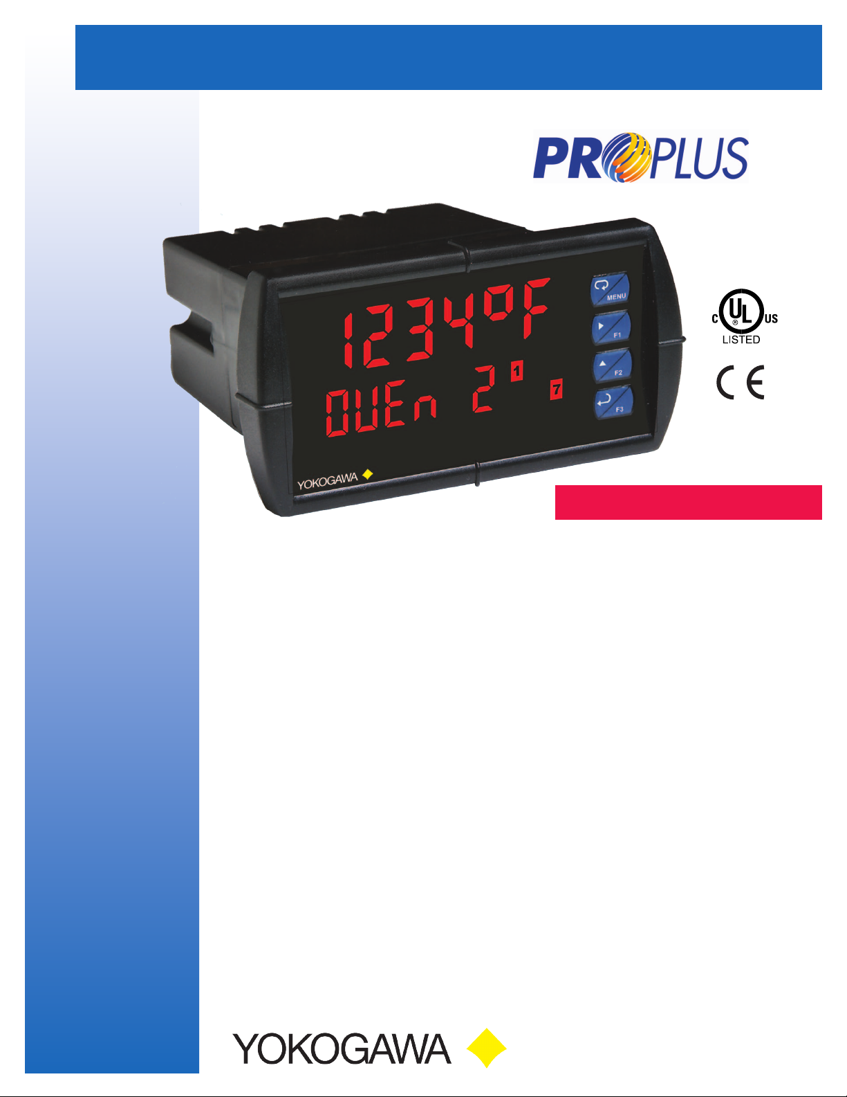
DUAL-LINE TEMPERATURE METER
PROPLUS • Model YPP7000
• J,K,T,E,R,S,B,N,CThermocouples
• 100or1000ΩPlatinum,10ΩCopper,120ΩNickelRTDs
• 1°or0.1°Resolution
• Averagesupto10RTDSensors
• AutomaticColdJunctionCompensation
• NEMA4X,IP65Front
• Universal85-265VACor12/24VDCInputPower
• LargeDual-Line6-CharacterDisplay,0.60"&0.46"
• ProgrammableDisplays&FunctionKeys
• SunlightReadableDisplayModels
• 2or4Relays+Isolated4-20mAOutputOptions
• External4-Relay&DigitalI/OExpansionModules
• USB,RS-232,RS-485SerialCommunicationOptions
• Modbus
• Free
®
RTUCommunicationProtocolStandard
PROPLUSSoftwareforOperation,
MonitoringandProgramming
2DartRoad•Newnan,Georgia30265
770-253-7000•800-888-6400
Fax:770-251-2088•www.yokogawa-usa.com
Page 2
YPP7000 DUAL-LINE TEMPERATURE METER
UV Resistant
Large
0.6" Digits
Sunlight Readable Models
(Actual Size)
Rugged Front
Dual-Line
6-Character
Display
User Congurable
Display
INTRODUCTION
The PROPLUS YPP7000 temperature meter boasts specications
and functionality that clearly makes it one of the most advanced
temperature meters available. Its dual-line 6-character display,
function keys, and optional expansion modules are only a few of
the special features available on the PROPLUS.
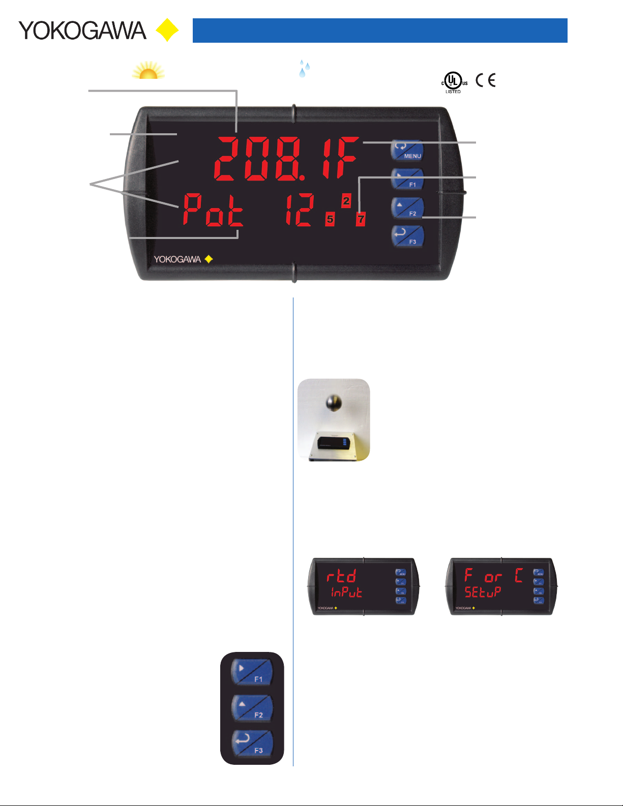
Front Panel
NEMA 4X Rated
Temperature
Units
Alarm
Status Indicators
Programmable
Function Keys
Optional SunBright Display Models
PROPLUS’s SunBright display models have an extraordinarily
bright LED display. They are perfect for applications where the
meter is in direct sunlight or in applications where visibility may be
impaired by smoke, fog, dust, or distance. This option is available
on all PROPLUS models.
Versatile
The YPP7000 accepts many more thermocouple types and RTDs
than earlier models. It can be congured to have either a 1° or 0.1°
display resolution on any type of sensor input. The lower display
makes conguration simpler. The display itself is quite congurable.
There are many relay functions for up to 8 relays; including an
Interlock Relay function. The 4-20 mA output can represent up to
12 different parameters/variables. This makes the YPP7000 one of
the most versatile meters on the market.
FRONT PANEL DISPLAY
Precise, Accurate, and More Informative
PROPLUS’s large 0.6" upper display provides an accurate and
precise 4 or 5-digit view of the temperature measurement.
Congurable
The upper display c an be programmed to indi cate current temper ature,
maximum or minimum temperature, alternating maximum/minimum
temperatures, one of eight alarm set points, or Modbus input. The
lower display can also be congured to display engineering units, set
points, user dened legends, or simply turned off.
Function Keys
There are three function keys available to the
user. These keys can be programmed to trigger
certain events (i.e. acknowledge alarms, reset
max and/or min, disable/enable output relays, or
hold current relay states), provide direct menu
access points, and more.
Rugged
A unique front panel design makes the
PROPLUS nearly impenetrable in typical
applications. Here, the PRO PLUS easily
survives a direct hit on the display from a
heavy 2" solid stainless steel ball dropped
from eight feet.
Easy to Use
The user friendly dual-line display makes the PROPLUS easy to set
up & program. Input selection and conguration are conveniently
set up via rear switches and front panel programming. Three
levels of password protection help maintain the reliability of the
programming.
Input Setup Display Setup
Three Tier Password Protection
The PROPLUS offers 3 levels of password protection:
• Level 1 protection allows the operator use of only the 3 pre-
congured function keys on the front panel without a password.
• Level 2 protection allows the operator use of only the function
keys and the ability to change set points without a password.
• Level 3 protection restricts the operator from using the function
keys and all meter conguration menus without a password.
2
Page 3

YPP7000 DUAL-LINE TEMPERATURE METER
Simplied & Dynamic Menu System
The PROPLUS minimizes the menu selections by auto-detecting
the installed options to determine what menu navigation is required.
For example, extra menu items for the relay expansion module,
I/O expansion, etc. are not present unless those options have
been installed. This is an example of keeping the product simply
sophisticated.
Max/Min Display
Max/Min (or Peak/Valley) is standard on the PROPLUS YPP7000.
Either display can be congured to show either maximum or minimum
excursion since last reset. The displays can also be congured to
toggle between Max and Min values. Both values can be simply reset
from the front panel.
Environmentally Protected
The PROPLUS has standard UV protection, a NEMA 4X front panel,
extremely durable face plate, performs in wide ambient operating
temperatures, and is CE Certied (high noise and RF immunity).
DIGITAL COMMUNICATIONS
Modbus® RTU Serial Communications
With the purchase of a serial communication adapter, PROPLUS
meters can communicate with any Modbus Master device using the ever-popular Modbus communications protocol that is
included in every PROPLUS. This greatly increases the exibility
of the meter. Modbus provides much more capability than read
PV and write set points. Below are some examples of other things
that can be done with PROPLUS’s Modbus communications.
• Send a 6-character message to the lower display upon an event
• Convert a digital value to a 4-20 mA signal
• Remote user control (i.e. change set points, acknowledge alarms)
• Input a Modbus digital PV (in place of analog input)
• Remote override of any, or all, relays and analog outputs
MULTIPLE SENSOR AVERAGING
The YPP7000 can nd the average temperature of up to 10 RTD
probes connected in parallel. This new calculated value would then
be treated as the PV (temperature) displayed on the meter. The
average temperature is also available via Modbus communications
and as the retransmitted value for the optional 4-20 mA output.
PROPLUS SOFTWARE
Congure, monitor, and datalog a PROPLUS YPP7000 from
a PC using PROPLUS Software (available for download at
www.yokogawa-usa.com) and a serial adapter.
Monitor & Datalog
SetupRelays
Remote MessageModbus PV Input
Meter Copy
The Copy feature is used to copy (or clone) all the settings from
one PROPLUS to other PROPLUS meter in about 20 seconds! The
Copy function is a standard feature on all meters. It does not require
a communications adapter, only an optional cable assembly, P/N
YPPA1200. See the ordering information for complete details.
3
Page 4

YPP7000 DUAL-LINE TEMPERATURE METER
FIELD EXPANSION MODULES
Add functionality to the PROPLUS in the eld with easy-to-
install external expansion modules. Add RS-232 or RS-485
communications, I/O modules (up to 2), and 4-relay expansion
module. The menu items for these modules do not appear until
the module is connected, simplifying the basic menu. Relay
and digital I/O modules are shown below with optional DIN rail
mounting kit, P/N YPPA1002.
YPPA1044 I/O Expansion Module
Four digital inputs and four digital outputs are available per
expansion module. The PROPLUS meter will accept two of these
modules. External digital inputs can function similarly to the front
panel function keys. They can be congured to trigger certain
events (i.e. acknowledge/reset alarms, reset max and/or min
values, disable/enable all output relays, and hold current relay
states), provide direct menu access point, or mimic front panel
keys. The I/O module can be used to congure the PROPLUS
remotely, in essence giving the user control of the four front
panel push buttons. This feature is particularly useful if the meter
is mounted inside an explosion-proof enclosure.
Digital outputs can be used to remotely monitor PROPLUS’s
alarm relay output states, or the states of a variety of actions and
functions executed by the meter.
YPPA1004 Relay Expansion Module
An external module containing four 3 A Form A (SPST) relays
can be added to the PROPLUS at anytime. Removable screw
terminal blocks accept 12 to 22 AWG wire.
OUTPUTS
Relay Outputs
The PROPLUS has up to four 3 A Form C relays (SPDT) with multiple
power loss fail-safe options. Relays can be congured for proper
protective action upon input loop break. Relay ON and OFF delay
times are user adjustable. Up to eight front panel indicators show alarm
and/or relay state. All relays can be congured for 0-100% deadband.
Relay Operation/Conguration
There are powerful relay functions that can be congured in the
PROPLUS meter, including:
• Automatic reset only (non-latching)
• Automatic + manual reset at any time (non-latching)
• Latching (manual reset only)
• Latching with clear (manual reset only after alarm
condition has cleared)
• User selectable fail-safe operation
• Relay action upon sensor break
• Time delay (on and off), independent for each relay
• Manual control mode
• Interlock relay mode
Front panel button or digital input may be assigned to acknowledge relays
programmed for manual reset.
Analog Output
The isolated analog retransmission signal can be congured
to represent the measured temperature (including average
temperature), maximum or minimum temperature, any of the
eight relay set points, manual control setting, or Modbus input.
While the output is nominally 4-20 mA, the signal will accurately
accommodate under- and over-ranges from 1 to 23 mA. A power
supply (24 V @ 40 mA) is standard with the 4-20 mA output option.
Manual Output Control
Take control of any output with this
feature. All relays can be forced
ON or O FF, an d th e 4- 2 0 mA ou t p u t
signal can be set to any value
within its range. When the relays
and 4-20 mA output are controlled manually, an LED labeled “M”
is turned on and the associated Alarm LEDs (1-8) ash every 10
seconds indicating that the meter is in manual control mode.
YPPA1232 & YPPA1485 &
YPPA8008 Communication
Modules
Serial communications on the PROPLUS
can be added anytime with external
YPPA1232 (RS-232) or YPPA1485 (RS-485),
or YPPA8008 (USB) communication adapters.
Free Modbus protocol with purchase of PROPLUS
serial communications modules.
Interlock Relay(s)
This function allows a process to use one or more very low
voltage input signals or simple switch contacts to control the
state of one or more internal “interlock” relays. A violation (i.e.
loss of input, open switch, or open circuit) forces one or more
N/O interlock relay contacts to open. One input can be used in
series with a number of interlock switches, or up to eight inputs
can be required to force-on one (or more) internal interlock
relays. Please see Application Note AN-1008 on our website for
more information. Requires YPPA1044 Digital I/O module.
LOAD
1 2
+5V I1
Interlock
Contact
(Digital Input)
4
Control
Relay
COMNO NC
4 36 5 2 1
Interlock
Relay
NEUT
115 VAC
COMNO NC
Page 5

YPP7000 DUAL-LINE TEMPERATURE METER
NEMA 4X FIELD ENCLOSURES
Thermoplastic NEMA 4X enclosures are constructed for either
indoor or outdoor use.
YPPA 2811
Plastic Low-Cost
YPPA2812
Plastic Low-Cost
CONNECTIONS
• Form C (SPDT) relays
• Isolated supply available even on
12/24 VDC input power models
• Removable terminal blocks
4-20 mA Output
Powered by
PROPLUS
• 2 or 4 relays + isolated 4-20 mA output option
+
-
RELAY4 RELAY3
4 36 5 2 1
COM NONO NC NC COM
RTD
TC
EXC T+ COM
312
SIGNAL
RELAY2 RELAY1
4 36 5 2 1
COM NONO NC NC COM
RTD
100
TC
10
TYPE
RANGE
1 2 3 4 5 6 7 8
M-LINK
MA OUT
3 2
24 V
+
POWER
1
RI- I+
-
21
• Universal 85-265 VAC or 12/24 VDC input power
• Thermocouple or RTD inputs
• M-Link for adding expansion modules
DIMENSIONS
R
C
+
C
NO
NC
NC
-
NO
C
C
NO
NC
NC
Optional
Connectors
Installed
3.61"
(92 mm)
4.68"
(119 mm)
Top View
2.45"
(62 mm)
0.59"
(15 mm)
1.76"
(45 mm)
6" (152 mm) Clearance
Side View
(121 mm)
4.77"
5.05"
(128 mm)
Notes:
1. Panel cutout required: 1.772" x 3.622" (45mm x 92mm)
2. Panel thickness: 0.040 - 0.250" (1.0mm - 6.4mm)
3. Mounting brackets lock in place for easy mounting
4. Clearance: Allow 6" (152 mm) behind the panel
NO
4.17"
(106 mm)
SPECIFICATIONS
Except where noted all specif ications apply to operation at +25°C.
General
Display: Upper display: 0.60" (15 mm) high. Lower display: 0.46" (12
mm) high. Both displays are 6-character (-99999 to 999999), red LEDs
with leading zero blanking. Temperature value is four or five-digit F/C,
based on configuration.
Resolution: 1° (up to four digits) or 0.1° (up to ve digits)
Display Intensity: Eight intensity levels
Display Update Rate: 5/second (200 ms)
Front Panel: NEMA 4X, IP65
Programming Methods: Four front panel buttons, digital inputs, PC and
PROPLUS software, Modbus registers, or cloning using Copy function.
Noise filter: Programmable from 2 to 199 (0 will disable filter)
Filter Bypass: Programmable from 0.1 to 99.9% of span
Recalibration: Calibrated at the factory. Recalibration is
recommended at least every 12 months.
Max/Min Display: Max / min temperature readings are stored until
reset by the user or until power to the meter is cycled.
Password: Three programmable passwords restrict modification of
programmed settings. Pass 1: Allows use of function keys and digital inputs.
Pass 2: Allows use of function keys, digital inputs and editing set/reset
points. Pass 3: Restricts all programming, function keys, and digital inputs.
Non-Volatile Memory: All programmed settings are stored in nonvolatile memory for a minimum of ten years if power is lost.
Power Options: 85-265 VAC 50/60 Hz, 90-265 VDC 20 W max, or
jumper selectable 12/24 VDC ±10%, 15 W max.
Fuse: Required external fuse: UL Recognized, 5 A max, slow blow; up
to 6 meters may share one 5 A fuse.
Normal Mode Rejection: Greater than 65 dB at 50/60 Hz
Isolation: 4 kV input/output-to-power line. 500 V input-to-output
Environmental: Operating temperature range: -20 to 65°C. Storage
temperature range: -40 to 85°C. Relative humidity: 0 to 90% non-condensing.
Connections: Removable screw terminal blocks accept 12 to 22 AWG wire,
RJ45 for external relays, digital I/O, and serial communication adapters.
Enclosure: 1/8 DIN, high impact plastic, UL 94V-0, color: black
Mounting: 1/8 DIN panel cutout required: 3.622" x 1.772"
(92 mm x 45 mm). Two panel mounting bracket assemblies are provided.
Tightening Torque: Screw terminal connectors: 5 lb-in (0.56 Nm)
Overall Dimensions: 4.68" x 2.45" x 5.64"
(119 mm x 62 mm x 143 mm) (W x H x D)
Weight: 9.5 oz (269 g)
UL File Number: UL & c-UL Listed. E348677; 508 Industrial Control
Equipment.
Warranty: 3 years parts & labor
Temperature Input
Input: Thermocouple J, K, T, E, R, S, B, N, C; RTD 100 Ω platinum
(0.00385 & 0.00392 cur ves), 10 Ω copper, 120 Ω nickel, 1000 Ω platinum
Input Impedance: Greater than 100 kΩ
Offset Adjust: User programmable offset adjust ±50.0 degrees
Temperature Drift: ±2°C maximum from 0 to 65°C ambient temperature;
±4°C maximum from -20 to 0°C ambient temperature
Sensor Break: Display flashes “Open”, relays can be programmed to
go “On”, “Off”, or to “Ignore” (detected as an upscale condition).
Averaging: Up to 10 RTDs connected in parallel can be averaged.
Accuracy & Range: See table below.
Type Range (°F) Range (°C) Accuracy
J -200 to 2000 -129 to 1093 ±1°C
K -200 to 2400 -129 to 1316 ±1°C
T -200 to 752 -129 to 400 ±1°C
E -200 to 1800 -129 to 982 ±1°C
R -50 to 3000 -46 to 1649 ±2°C
S -50 to 3000 -46 to 1649 ±2°C
B 752 to 3300 400 to 1816 ±2°C
N -100 to 2300 -73 to 1260 ±2°C
C 32 to 4100 0 to 2260 ±2°C
10 Ω -328 to 500 -200 to 260 ±0.1°C
100 Ω -328 to 1562 -200 to 850 ±0.4°C
120 Ω -110 to 500 -79 to 260 ±0.1°C
1000 Ω -328 to 900 -200 to 482 ±0.4°C
5
Page 6

YPP7000 DUAL-LINE TEMPERATURE METER
Relays
Rating: 2 or 4 SPDT (Form C) internal and/or 4 SPST (Form A) external;
rated 3 A @ 30 VDC and 125/250 VAC resistive load; 1/14 HP (≈ 50 watts)
@ 125/250 VAC for inductive loads such as contactors, solenoids, etc.
Noise Suppression: Noise suppression is recommended for each relay
contact switching inductive loads.
Deadband: 0-100% of span, user programmable
High or Low Alarm: User may program any alarm for high or low trip
point. Unused alarm LEDs and relays may be disabled (turned off).
Relay Operation: automatic (non-latching), latching (requires manual
acknowledge), sampling (based on time), pump alternation control (2 to 8
relays), Off (disable unused relays and enable interlock feature, manual
on/off control mode).
Time Delay: 0 to 999.9 seconds, on & off relay time delays.
Programmable and independent for each relay.
Fail-Safe Operation: Programmable and independent for each relay.
Note: Relay coil is ene rgized in no n-ala rm condition. In c ase of power failure , relay will go to alarm s tate.
Auto Initialization: When power is applied to the meter, relays will reect
the state of the input to the meter.
Isolated 4-20 mA Transmitter Output
Output Source: PV (temperature), max, min, set points 1- 8, manual
control setting, or Modbus input
Scaling Range: 1.000 to 23.000 mA for any display range
Calibration: Factory calibrated 4-20 mA output
Accuracy: ± 0.1% of span ± 0.004 mA
Temperature Drift: 0.4 μA/°C max from 0 to 65°C ambient,
0.8 μA/°C max from -40 to 0°C ambient
Note: Ana log outpu t drift is separate from inp ut drif t.
Isolated Transmitter Power Supply: Terminals I+ & R: 24 VDC ± 10%
@ 40 mA maximum, may be used to power the 4-20 mA output or other
devices. Present on both AC & DC powered units.
External Loop Power Supply: 35 VDC maximum
Output Loop Resistance:
Power supply Minimum Maximum
24 VDC 10 Ω 700 Ω
35 VDC (external) 100 Ω 1200 Ω
Serial Communications
Protocol: Modbus® RTU
Meter Address/Slave ID: 1 - 247
Baud Rate: 300 - 19,200 bps
Transmit Time Delay: Programmable between 0 and 199 ms
Data: 8 bit (1 start bit, 1 or 2 stop bits)
Parity: Even, odd, or none with 1 or 2 stop bits
Byte-to-Byte Timeout: 0.01 - 2.54 seconds
Turn Around Delay: Less than 2 ms (xed)
Note: Refe r to the YPP 600 0/Y PP700 0 Modbus R egister Tabl es located at
www.yokogawa-usa .com for details.
Digital I/O Expansion Module
Channels: 4 digital inputs & 4 digital outputs per module
System: Up to 2 modules for a total of 8 inputs & 8 outputs
Digital Input Logic: High: 3 to 5 VDC Low: 0 to 1.25 VDC
Digital Output Logic: High: 3.1 to 3.3 VDC Low: 0 to 0.4 VDC
Source Current: 10 mA maximum
Sink Current: 1.5 mA minimum
+5 V Terminal: To be used as pull-up for digital inputs only.
ORDERING INFORMATION
PROPLUS YPP7000 • Standard Models
85-265 VAC
Model
YPP7000-6R0 YPP7000-7R0 None
YPP7000-6R2 YPP7000-7R2 2 Relays
YPP7000-6R3 YPP7000-7R3 4-20 mA Output
YPP7000-6R4 YPP7000-7R4 4 Relays
YPP7000-6R5 YPP7000-7R5 2 Relays & 4-20 mA Output
YPP7000-6R7 YPP7000-7R7 4 Relays & 4-20 mA Output
PROPLUS YPP7000 • SunBright Display Models
85-265 VAC
Model
YPP7000-6H0 YPP7000-7H0 None
YPP7000-6H2 YPP7000-7H2 2 Relays
YPP7000-6H3 YPP7000-7H3 4-20 mA Output
YPP7000-6H4 YPP7000-7H4 4 Relays
YPP7000-6H5 YPP7000-7H5 2 Relays & 4-20 mA Output
YPP7000-6H7 YPP7000-7H7 4 Relays & 4-20 mA Output
Model Description
YPPA1002 DIN Rail Mounting Kit for Two Expansion Modules
YPPA1004 4-Relay Expansion Module
YPPA1044 4 Digital Inputs & 4 Digital Outputs Module
YPPA1200 Meter Copy Cable
YPPA1232 RS-232 Serial Adapter
YPPA1485 RS-485 Serial Adapter
YPPA8008 USB-Serial Adapter
YPPA7485-I RS-232 to RS-485 Isolated Converter
YPPA7485-N RS-232 to RS-485 Non-Isolated Converter
YPPA8232-N USB to RS-232 Non-Isolated Converter
YPPA8485-I USB to RS-485 Isolated Converter
YPPA8485-N USB to RS-485 Non-Isolated Converter
YPPX6901 Suppressor (snubber): 0.01 μF/470 Ω, 250 VAC
Model Description
YPPA2811 1 Meter Plastic NEMA 4X Enclosure
YPPA2812 2 Meter Plastic NEMA 4X Enclosure
12/24 VDC
Model
12/24 VDC
Model
Accessories
Enclosures
Options Installed
Options Installed
4-Relay Expansion Module
Relays: Four Form A (SPST) rated 3 A @ 30 VDC and 125/250 VAC
resistive load; 1/14 HP (≈ 50 watts) @ 125/250 VAC for inductive loads.
Disclaimer
The info rmatio n contai ned in thi s document is subject to chang e withou t notice. Yokog awa
Corporation of America makes no representations or warranties with respect to the contents
hereof, and speci cally d isclaims any impli ed warra nties of me rchantability or tnes s for a
particular purpose.
©2011 Yokogawa Corporation of Amer ica. All r ights reserved
2DartRoad•Newnan,Georgia30265
770-253-7000•800-888-6400
Fax:770-251-2088•www.yokogawa-usa.com
LDS7000YK_B 11/11
 Loading...