

Page 1

User's
2786
Manual
Test Equipment Depot - 800.517.8431 - 99 Washington Street Melrose, MA 02176 - TestEquipmentDepot.com
Decade Resistance Box
IM 2786-01E
8th Edition: Oct. 2017 (YMI)
Page 2

IM 2786-01E
Introduction
Thank you for purchasing the 2786 Decade Resistance Box.
This User’s manual contains useful information regarding
the instrument’s functions and operating procedures,
as well as precautions that should be observed during use.
Before using this product, thoroughly read this manual
to understand how to use it properly.
Keep this manual in a safe place for quick reference in
the event that a question arises.
Contact information of Yokogawa offices worldwide is
provided on the following sheet.
PIM 113-01Z2 Inquiries List of worldwide contacts
Notes
• The information contained in this manual is subject to
change without notice. Furthermore, the actual display
items may differ slightly from the ones appearing in
this manual.
• Every effort has been made to ensure the information
contained herein is accurate.
However, should any concerns, errors, or emissions
come to your attention, or if you have any comments,
please contact us.
• Copying or reproduction of any or all of the content of
this manual without Yokogawa’s permission is strictly
prohibited.
8th Edition: October 2017
All Rights Reserved. Copyright ©
2017, Yokogawa Test & Measurement Corporation
― i ―
Page 3
IM 2786-01E
WARNING
CAUTION
Cautionary Notes for Safe Use of the Product
When operating the instrument, be sure to observe
the cautionary notes given below to ensure correct and
safe use of the instrument. If you use the instrument in
any way other than as instructed in this manual,
the instrument’s protective measures may be impaired.
This manual is an essential part of the product;
keep it a safe place for future reference.
YOKOGAWA is by no means liable for any damage
resulting from use of the instrument in contradiction to
these cautionary notes.
■ The following safety symbols are used on
the instrument and in the manual:
Danger! Handle with Care.
This symbol indicates that the operator must refer
to an explanation in the User’s Manual or
Service Manual in order to avoid risk of injury or
loss of life of personnel or damage to
the instrument.
Indicates a hazard that may result in the loss of life or
serious injury of the user unless the described instruction
is abided by.
Indicates a hazard that may result in an injury to the user
and/or physical damage to the product or other equipment
unless the described instruction is abided by.
― ii ―
Page 4
IM 2786-01E
■ Since mishandling the instrument can result in
WARNING
WARNING
an accident that may lead to injury or death of
the operator, such as an electric shock,
be sure to observe the following instructions.
● Measurement
• Always maintain the instrument within the limits for allowable
current, voltage and power, during operation.
If there is more than one limit for any of these parameters,
the lowest limit takes precedence.
• Only operate the instrument on an input-to-ground supply
voltage of no greater than 250 V.
• The terminals and internal circuitry may become electrified
to high voltages and extremely hot depending on
the instrument’s condition of use.
Do not touch these parts.
● Grounding
• To avoid electric shock, be sure to apply protective
grounding to the grounding terminal.
● Protective Measure
• If a crack appears in the instrument after it has been
accidentally dropped or bumped, the safety-purpose
insulation may be damaged.
By all means do not use the instrument,
but ask the manufacturer for repair.
● Operating Environment
• Do not operate the instrument in a flammable or explosive
gas atmosphere.
• Do not operate the instrument if there is any condensation
on it.
● Do Not Remove the Casing or Disassemble
• Only Yokogawa service personnel are authorized to remove
the casing or disassemble or modify the instrument.
Do not attempt to repair the instrument yourself,
as doing so is extremely dangerous.
(If you are rack-mounting the instrument,
use it correctly according to the handling procedure.)
― iii ―
Page 5

IM 2786-01E
CONTENTS
Introduction ..................................i
Cautionary Notes for Safe Use of the Product .......ii
1. GENERAL ................................1
1.1 Description............................1
1.2 Features .............................1
1.3 Specification .........................2
2. NAMES AND FUNCTIONS OF COMPONENTS ..3
3. OPERATION . . . . . . . . . . . . . . . . . . . . . . . . . . . . . . 5
4. MAINTENANCE ...........................6
5. CIRCUIT DIAGRAM ........................7
Disposing the Product.........................10
― iv ―
Page 6

IM 2786-01E
1. GENERAL
1.1 Description
The 2786 Decade Resistance Boxes are stable variable
resistors with 6 dials which can be set accurately and
quickly. They are used at DC/low frequencies.
These resistance boxes can be used in combination with
voltage or current generators for adjusting voltage or
current.
They can also be used as dummy load resistances or
in an arm of an AC bridge, and are indispensable for
various experiments and studies and as testing facilities
for production lines.
Two types are available as follows.
DescriptionModel
278610
278620
0.1 to 111, 111 Ω (6 dials)
1 to 1111, 110 Ω (6 dials)
1.2 Features
(1) Low Temperature coefficient, little resistance
shift due to aging
These resistance elements have temperature
coefficient of less than ±10 ppm/°C and excellent
long-term stability.
(2) Small Residual Resistance
Errors due to switch contact resistance, wiring resistance
and the fluctuation of contact resistance due to
dial position, are extremely small.
Yokogawa’s Decade Resistance Boxes are the product
of years of experience.
(3) Metal Case
Resistance elements are accommodated in a metal case
to minimize the effect of external influences electrical and
magnetic fields, short term temperature variations,
physical damage or contamination.
(4) Compact and light weight
These instruments are compact, lightweight and
portable.
(5) Rack-mounted type
The 2786 can be rack-mounted, if the case is removed.
― 1 ―
Page 7

IM 2786-01E
1.3 Specifications
6
User's Manual 1 copy
Rated Input Power:
greater than maximum rated voltage to the terminals.
greater than maximum rated voltage to the terminals.
Number of Dials:
Resistance Range:
Residual Resistance:
Maximum Permissible Input Power:
Operating Temperature Range:
Storage Temperature Range:
Maximum Circuit Voltage:
Dielectric Strength:
Insulation Resistance:
Dimensions:
Weight:
Accessory:
Accuracy and Temperature coefficient:
C, humidity of 45 to 75%
*1
*2
R : Resistance value at 23ºC
278610; 0.1 to 111,111 Ω
278620; 1 to 1111,110 Ω
less than 23 mΩ
0.3 W/step,
within 3 W in total avoid applying voltages
0.5 W/step,
within 5 W in total avoid applying voltages
0 to 40ºC, Humidity 25 to 85%RH
1500 VAC for one minute
More than 500 MΩ at 500 VDC
Approx. 116 × 497 × 140 mm
Approx. 3.5 kg
−10 to 50ºC
250 VDC
― 2 ―
Dial
Step
0.1 Ω
1 Ω
10 Ω
100 Ω
1 kΩ
10 kΩ
100 kΩ
Accuracy
±2%
±0.5%
±0.1%
±0.05%
±0.05%
±0.1%
±0.1%
Temperature Coefficient
*1
α23(×10-6/ºC) β (×10-6/ºC2)
±250
±100
±20
±10
±10
±50
±50
−0.4 to −0.8
−0.4 to −0.8
−0.4 to −0.8
−0.4 to −0.8
−0.4 to −0.8
±0.1
±0.1
• At a temperature of 23±3º
and input power less than 0.1 W.
• The resistance values do not include the residual
resistance.
The effects increase for small resistance settings.
Variation of resistance with temperature change is
given by the following equation
Rt = R {1 + α (t − 23) + β (t −23) }
2323
2
Where Rt : Resistance value at tºC
23
*2
Page 8
IM 2786-01E
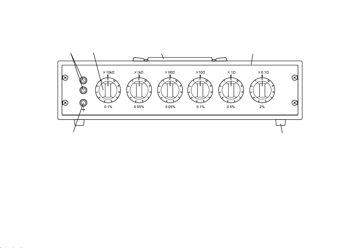
2. NAMES AND FUNCTIONS OF COMPONENTS
[ 2 ][ 1 ] [ 3 ] [ 4 ]
the front panel.
H
L
[ 6 ]
[ 1 ] Resistance Terminals:
Addition of the values indicated on the dials
gives the resistance between the terminals.
[ 2 ] Resistance Setting Decade Dials:
Set the desired resistance value
for each digital.
[ 5 ]
Figure 2.1 278610
[ 3 ] Carrying Handle:
[ 4 ] Metal Case:
[ 5 ] Rubber Feet:
[ 6 ] Earth Terminal:
This earth (ground) terminal is connected to
― 3 ―
Page 9

IM 2786-01E
Figure 2.2 278620
H
L
― 4 ―
Page 10

IM 2786-01E
Table 3.1
3. OPERATION
(1) Addition of the values indicated on the dials gives
the resistance between the terminals.
That is, to obtain a resistance of 12345.6 Ω with
the 278610, ×10 kΩ, ×1 kΩ, ×100 Ω, ×10 Ω,
×1 Ω, and ×0.1 Ω dials should be set to
1, 2, 3, 4, 5, and 6 respectively.
(2) The percentage error and maximum permissible input
current for each resistance element-corresponding to
a power dissipation of 0.3 W are shown in Table 3.1.
The percentage error is also shown on the instrument
front panel.
Be careful not to exceed the maximum permissible
input current or voltage ratings, or the resistance
elements may shift in value.
When two or more dials are used simultaneously,
the allowable maximum current is that of
the higher resistance value dial.
(3) Of the two resistance terminals, the one which is closer
to the earth terminal
Consequently, when the instrument is used for
an unbalanced circuit, this terminal should be connected
to lower potential side of the circuit.
is the low resistance (L) terminal.
Dial
Step
0.1 Ω
1 Ω
10 Ω
100 Ω
1 kΩ
10 kΩ
100 kΩ
Accuracy
±2%
±0.5%
±0.1%
±0.05%
±0.05%
±0.1%
±0.1%
Operating
Current
1.7 A
550 mA
170 mA
55 mA
17 mA
5.5 mA
250 V (200 kΩ to 1 MΩ)
1.7 mA (100 kΩ)
Maximum
Allowable Current
2.2 A
710 mA
220 mA
71 mA
22 mA
7.1 mA (10 kΩ to 30 kΩ)
250 V (40 kΩ to 100 kΩ)
250 V
(4) Dielectric strength between instrument terminals and
case: withstands1500 VAC for one minute, and
insulation resistance between instrument terminals and
case is more than 500 MΩ at 500 VDC.
However these conditions depend on ambient
temperature and humidity.
Observe maximum rated voltage.
― 5 ―
Page 11

IM 2786-01E
(5) As enclosed type dial switches are employed in
the instrument, switch contacts resistance is stable
even in dusty areas or where corrosive gases, etc.
However, when the instrument has not been used for
sometimes, turn the dials several times before use.
(6) If electrical or mechanical shocks appear to have
damaged the instrument, check, its resistance.
The 2768 Precision Wheatstone Bridge is suitable.
(7) The 2786 can be rack-mounted.
When rack-mounted, the case is removed,
so place a simple cover to protect components,
such as resistance elements and switches.
4. MAINTENANCE
To insure accurate measurement it is essential to
maintain the instrument in good condition.
Therefore, avoid the following environments:
• Where humidity is high.
• Where the instrument is exposed to direct sunlight,
or high temperature.
• Where the instrument is next to a heat source.
• Where the instrument will be subjected to severe
vibration.
• Where the atmosphere is salty, contains corrosive
gas, dust or dirt.
Calibration
Recommended calibration period: 1 year
Periodic calibration is recommended to maintain
the accuracy of the instrument.
― 6 ―
Page 12

IM 2786-01E
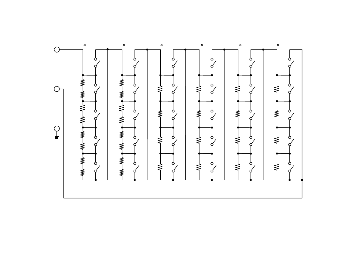
5. CIRCUIT DIAGRAM
Figure 5.1 278610
10 kΩ
10 Ω
1 Ω 0.1 Ω100 Ω
1 kΩ
H
L
R601
R602
R501
R401
R301
R201
R101
R603
R604
R605
R606
R607
R608
R502
R503
R504
R402
R403
R404
R302
R303
R304
R202
R203
R204
R102
R103
R104
S6 S5 S 4 S3 S2 S 1
― 7 ―
Page 13
IM 2786-01E
R701
Figure 5.2 278620
100 kΩ
100 Ω
10 Ω 1 Ω1 kΩ
10 kΩ
H
L
R702
R601
R602
R501
R401
R301
R201
R703
R704
R705
R706
R707
R708
R603
R604
R605
R606
R607
R608
R502
R503
R504
R402
R403
R404
R302
R303
R304
R202
R203
R204
S7 S6 S 5 S4 S3 S 2
― 8 ―
Page 14

IM 2786-01E
Reference
Designation
R101
R102
R103
R104
R201
R202
R203
R204
R301
R302
R303
R304
R401
R402
R403
R404
R501
R502
R503
R504
0.1 Ω
0.2 Ω
0.2 Ω
0.5 Ω
1 Ω
2 Ω
2 Ω
5 Ω
10 Ω
20 Ω
20 Ω
50 Ω
100 Ω
200 Ω
200 Ω
500 Ω
1 kΩ
2 kΩ
2 kΩ
5 kΩ
Description
WIRE-WOUND
Reference
Designation
R601
R602
R603
R604
R605
R606
R607
R608
R701
R702
R703
R704
R705
R706
R707
R708
5 kΩ
5 kΩ
10 kΩ
10 kΩ
10 kΩ
10 kΩ
25 kΩ
25 kΩ
50 kΩ
50 kΩ
100 kΩ
100 kΩ
100 kΩ
100 kΩ
250 kΩ
250 kΩ
Description
MET-FLM
― 9 ―
Page 15

IM 2786-01E
Disposing the Product
Waste Electrical and Electronic Equipment (WEEE),
Directive
(This directive is valid only in the EU.)
This product complies with the WEEE directive marking
requirement.
This marking indicates that you must not discard
this electrical/electronic product in domestic household
waste.
Product Category
With reference to the equipment types in the WEEE
directive, this product is classified as a "Monitoring and
control instruments" product.
When disposing products in the EU, contact your local
Yokogawa Europe B.V. office.
Do not dispose in domestic household waste.
― 10 ―
Page 16

Printed in Japan
 Loading...