

Page 1

User's
2752
Manual
Test Equipment Depot - 800.517.8431 - 99 Washington Street Melrose, MA 02176 - TestEquipmentDepot.com
Precision Double Bridge
IM 2752-01E
IM 2752-01E
6th Edition: Oct. 2017 (YMI)
Page 2

IM 2752-01E
Introduction
Thank you for purchasing our Precision double bridge.
This manual describes the specifications and handling precautions of the Precision double bridge.
Before using this product, thoroughly read this manual to understand how to use it properly.
Contact information of Yokogawa offices worldwide is provided on the following sheet.
PIM 113-01Z2: Inquiries List of worldwide contacts
Notice regarding This User’s Manual
• The information covered in this User’s manual is subject to change without prior notice.
• Every effort has been made to ensure accuracy in the preparation of this manual.
Should any errors or omissions come to your attention however, please inform YOKOGAWA accordingly.
• YOKOGAWA is by no means liable for any damage resulting from the user’s mishandling of the product.
• This manual is intended to describe the functions of this product.
YOKOGAWA does not guarantee that these functions are suited to the particular purpose of the user.
― i ―
Page 3

IM 2752-01E
Cautionary Notes for Safe Use of the Product
WARNING
When operating the instrument, be sure to observe the cautionary notes given below to ensure correct and
safe use of the instrument.
If you use the instrument in any way other than as instructed in this manual, the instrument’s protective
measures may be impaired.
This manual is an essential part of the product; keep it a safe place for future reference.
YOKOGAWA is by no means liable for any damage resulting from use of the instrument in contradiction to
these cautionary notes.
■ The following safety symbols are used on the instrument and in the manual:
Danger! Handle with Care.
This mark indicates that operator must refer to an explanation in
the instruction manual in order to avoid risk of injury or death of
personnel or damage to the instrument.
This mark indicates earth (ground).
■ Since mishandling the instrument can result in an accident that may lead to
injury or death of the operator, such as an electric shock, be sure to observe
the following instructions.
● Protective Measures
• If a crack appears in the instrument after it has been accidentally dropped or bumped,
the safety-purpose insulation may be damaged.
By all means do not use the instrument, but ask the manufacture for repair.
● Connection
• To avoid electric shock, be sure to apply protective grounding to the grounding terminal.
• Install a protection fuse as shown in the example of measurement.
● Measurement
• Always maintain the instrument within the limits for allowable current, voltage and power,
during operation.
If there is more than one limit for any of these parameters, the lowest limit takes precedence.
● External Power Supply
• Only operate the instrument on a supply voltage no greater than 60 VDC.
● Operating Environment
• Do not operate the instrument in a flammable or explosive gas atmosphere.
• Do not operate the instrument if there is any condensation on it.
● Do Not Remove the Case or Disassemble
• Do not open the case except when replacing batteries.
Only Yokogawa service personnel are authorized to remove the casing or disassemble or
modify the instrument.
Do not attempt to repair the instrument yourself, as doing so is extremely dangerous.
― ii ―
Page 4

IM 2752-01E
CONTENTS
Introduction ............................................................. i
Cautionary Notes for Safe Use of the Product ..................................ii
1. GENERAL ...........................................................1
2. SPECIFICATIONS.....................................................2
3. COMPONENT NAMES AND FUNCTIONS..................................4
4. ACCESSORY COMPONENTS ...........................................6
4.1 Galvanometer (Null-detector).........................................6
4.2 Battery and Current Adjusting Resistor .................................7
5. HANDLING ..........................................................8
5.1 Preparation ......................................................8
5.1.1 Connection for Battery ...............................................8
5.1.2 Connection for Galvanometer .........................................9
5.1.3 Connection for Unknown Resistance....................................9
5.1.4 Connection for External Standerd Resistor . . . . . . . . . . . . . . . . . . . . . . . . . . . . . . 10
5.1.5 Grounding .......................................................12
5.2 Operation .......................................................12
6. MAINTENANCE .....................................................14
6.1 Precaution for handling ............................................14
6.2 Inspection.......................................................15
6.2.1 Preliminary inspection ..............................................15
6.2.2 Inspection of standard resistors (R11 to R16) ............................15
6.2.3 Overall inspection .................................................16
― iii ―
Page 5

IM 2752-01E
7. CIRCUIT PRINCIPLE .................................................17
7.1 Basic Principle ...................................................17
7.2 Error ...........................................................18
7.2.1 Error due to current lead resistance....................................18
7.2.2 Error due to potential lead . . . . . . . . . . . . . . . . . . . . . . . . . . . . . . . . . . . . . . . . . . . 18
7.2.3 Error of standard resistor ............................................19
8. CIRCUIT DIAGRAM ..................................................21
― iv ―
Page 6

IM 2752-01E
1. GENERAL
This equipment is a precision DC low resistance measuring instrument
which is designed for precise measurement of values under 100 Ω.
This instrument uses resistance wire made of choice material aged for a long period of time.
In addition, special consideration is taken in locating guards which are firmly enclosed in
the metallic casing, so that they can be stably used for a long period of time.
Detailed five-figure readings are available with six built-in standard resistors,
three decade dials, and slide resistance.
The in-line decade indication system is employed to express resistance values,
insuring rapid reading.
This instrument can be used also for measurement of electric conductivity of a conductor and
calibration of a resistance standard, as well as for precision measurement of general resistances.
In addition, is designed for use in combination with accessories for large-capacity shunt checks and
measurement of bar conductor resistance.
― 1 ―
Page 7

IM 2752-01E
2. SPECIFICATIONS
0.10000 mΩ abs to 111.10 Ω abs
Ω.
Measuring range:
Measuring Arm (at multiplier
Multiplier:
Accuracy:
Current Rating of standard resistance:
Dimensions:
Insulation resistance:
between the case and the circuit
Weight:
Accessories: Two Plugs, User's manual
(Effective up to five digits)
(Ω abs: Absolute ohms)
× 1):
1st dial
2nd dial
3rd dial
4th dial
× 100, × 10, × 1, × 0.1, × 0.01, and × 0.001
±(0.03% of reading + 1 μΩ)
with ambient temperature of 23 ± 2.5°C
±(0.05% of reading + 1 μΩ)
with ambient temperature of 10 to 40°C
The lead resistance between C
× 100: 0.05 A
× 10: 0.15 A
× 1: 0.5 A
100 mΩ × 10
10 mΩ × 10
1 mΩ × 10
0.05 mΩ to 1.05 mΩ
(continuously variable)
(Minimum scale division: 0.01 mΩ)
terminal and Rx is less than 10 m
2
× 0.1: 3 A
× 0.01: 10 A
× 0.001: 30 A
Approx. 316 × 497 × 140 mm (not including rubber feet)
Note: Standard rack mounting is available.
100 MΩ or more at 500 VDC
Approximately 11.5 kg
― 2 ―
Page 8

IM 2752-01E
Accessories (Available upon request)
resistance value: approx. 2.5 mΩ
(1) Measuring cords (2753)
(2) Clamp device (2754)
Current cord (two):
2 m long,
resistance value: approx. 3 mΩ
Voltage cord (two):
2 m long,
resistance value: approx. 8 mΩ
(A clamp fitting is attached to the end of each cord.)
Effective measuring length of sample:
500 mm
(Distance between voltage terminals)
Maximum diameter of sample:
Minimum length of sample:
Current cord (two):
500 mm long,
25 mm
650 mm
resistance value: approx. 1 mΩ
Voltage cord (two):
500 mm long,
― 3 ―
Page 9

IM 2752-01E
3. COMPONENT NAMES AND FUNCTIONS
[5]
[2]
[8]
[9] [6]
[7] [10]
[3]
Fig. 3.1 Front Panel
P1
C1
Rx
MULTIPLY
1 0.1
10
0.15 0.5 3
2
6
7
8
9
10
G2 G1 G0 Gs
[4]
P2
0.01
10 30
C2
0.001
P1S
P2S P2S
YOKOGAWA
DOUBLE BRIDGE
4
3
2
1
0
[1]
2752
9
10
BA
GA GUARD
GA
BA
58
1
0
10
11
1
2
3
4
m Ω
9
8
7
6
5
Fig. 3.1 shows dial and terminal arrangement of this instrument.
[1] DIALS: I, II, III, IV
for use in adjustment of measuring arms
[2] MULTIPLYING FACTOR SWITCH PLUG:
to changeover the multiplying factors, by replacing two plugs at the same time.
[3] BA KNIFE SWITCH:
to be used as ON ‒ OFF, or to reverse the circuit current
[4] GALVANOMETER BUTTON SWITCH:
to select sensitivity; on G2 or G1 or C0 gives the highest sensitivity, and G1 is more sensitive than G2.
The use of Gs is to short circuit the galvanometer.
These G switches are clamped by turning them clockwise or counter-clockwise, after pushing them down.
― 4 ―
Page 10

IM 2752-01E
[5] Rx TERMINAL:
P P and P
1S
P and P
2S
consisting of C1, C2, P1, P2 terminals, for the connection to an unknown resistance.
[6] GA TERMINAL:
for the connection to the galvanometer.
[7] BA TERMINAL:
for the connection to the DC Power source (Battery).
2S
[8]
2S
TERMINAL:
These are the potential terminals to be used for the connection external standard resistance.
2S
[9]
TERMINAL:
for the connection to the compensation resistance ( )
[10] EARTH TERMINAL:
being connected to the panel.
― 5 ―
Page 11

IM 2752-01E
4. ACCESSORY COMPONENTS
Table 4.1
The following accessories are required for the operation of 2752.
4.1 Galvanometer (Null-Detector)
The galvanometer should have high sensitivity and a stable "0" position.
Sensitivity of the galvanometer depends upon the amount of unknown resistance and current
flowing through this unknown resistance.
For this, refer to Table 4.2 below.
The 2709 DC Electronic Galvanometer of its sensitivity of 0.2 μV is recommended for use.
When measuring resistance for a larger range than × 1,
the handy Electronic Galvanometer 2707 is recommended.
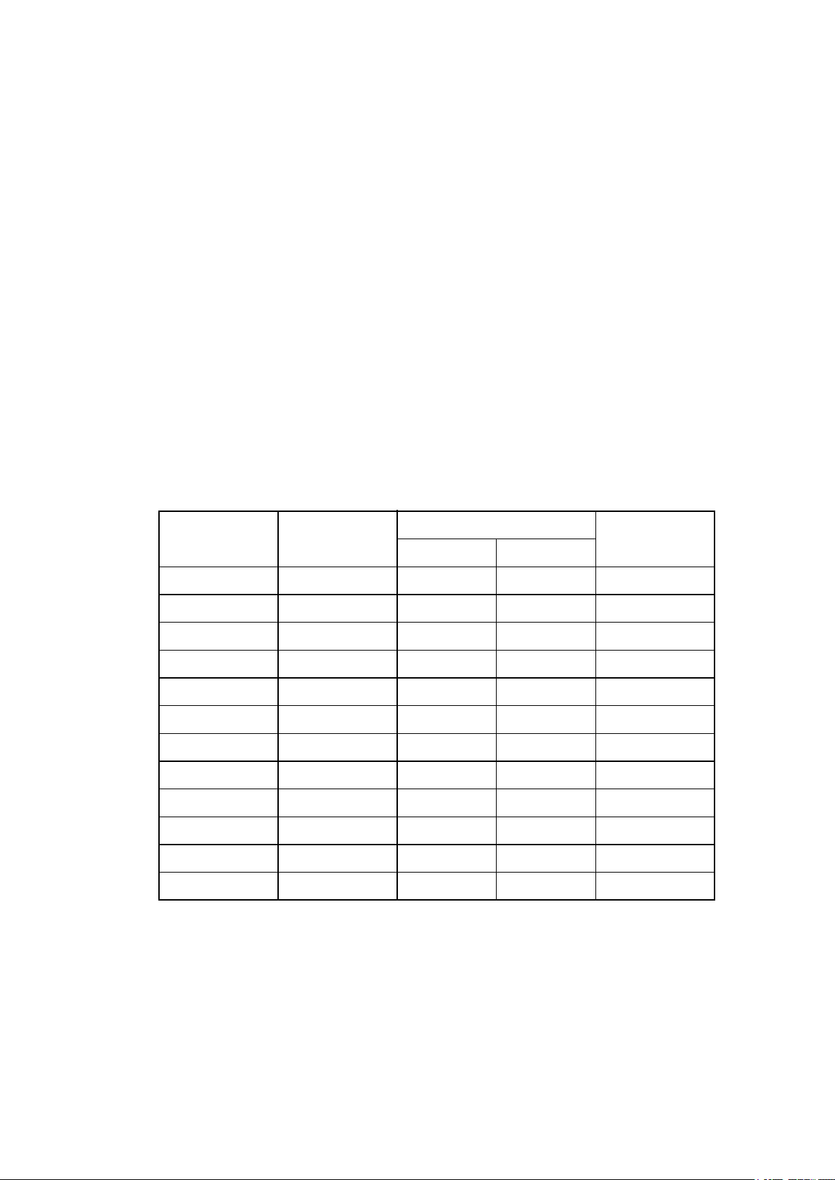
Model
Item
2707 2709
Sensitivity
10 × 10 V/div.
Internal Resistance
Period
Note:
Model 2707 and 2709 have been discontinued.
-6
9 kΩ
3 sec.
2 × 10 A/div.
-10
1 kΩ
0.5 sec.
― 6 ―
Page 12
IM 2752-01E
4.2 Battery and Current Adjusting Resistor
Relationship of Measuring Sensitivity and Current
The capacity of the battery depends on the resistance value of an unknown resistance,
however, its capacity is required to be, in general, more than 20 Ah at the voltage 2 V to 4 V.
A battery having large capacity is needed particularly for the measurement of low resistance at
heavy current. A slide resistor may often become useful.
It is connected in series to the battery for the control on the circuit current.
YOKOGAWA provides a group of slide resistors. The 2791 for such uses.
They are supplied in: 4.7 Ω (6 A max.), 10 Ω (4 A max.), 39 Ω (2 A max.).
For current monitoring, 2012 DC volt-ammeter (class 0.5) or
2051 (miniature DC ammeter (0.3 to 30 A, class 1.0) are recommended.
Table 4.2 shows the approximate current by which 1/10000 of unknown resistance change
can be detected with deflection of more than one scale division
when this instrument is used with a galvanometer.
Note:
Model 2791 and 2709 have been discontinued.
Unknown
resistance (Ω)
100
10
10
1
1
0.1
0.1
0.01
0.01
0.001
0.001
0.0001
Magnification
× 100
× 100
× 10
× 10
× 1
× 1
× 0.1
× 0.1
× 0.01
× 0.01
× 0.001
× 0.001
2708
0.0022
0.011
0.022
0.11
0.22
(1.1)
2.2
Table 4.2
Current Value (A)
2709
0.00008
0.00026
0.0008
0.0026
0.008
0.026
0.08
0.26
0.8
2.6
8
26
Current Rating
with 2752
0.05
0.05
0.15
0.15
0.5
0.5
3
3
10
10
30
30
― 7 ―
Page 13

IM 2752-01E
5. HANDLING
Fig. 5.1 Connecting Diagram
This instrument and accessories should be correctly connected in accordance with
the diagram shown in Fig. 5.1 and the following instructions.
H
L
Rx
C1
P1
P2 C2
G
E
2709*
Galvanometer
Rx
G1 GSG0G2
Double bridge 2752
GA
BAGUARD
DC Meter (A)
2012
*: Model 2709 and 2791 have been discontinued.
5.1 Preparation
5.1.1 Connection for Battery
(1) Capacity of the leads to be used for this connection should be large enough to
sustain heavy current flow.
It is desirable for the leads to be of copper with the diameter about 3.6 mm or
equivalent covered with suitable insulation material.
Fuse
Battery
Slide resistor
2791*
(2) The battery should have a fuse.
(3) Try to make use of an ammeter to check over-current flow in a measuring object.
Be careful not to overload the battery.
(4) Put the leads together.
This will minimize the forming of magnetic field around them.
― 8 ―
Page 14

IM 2752-01E
5.1.2 Connection for Galvanometer
(1) When using the Electronic Galvanometer, 2709
(a) Warm up for several minutes.
(b) Use the attached low thermoelectromotive force type cord as the input cord,
avoiding the effects of thermoelectromotive force.
(c) Equip the input cord with a guard to prevent DC leakage.
Ground the ground terminal of the galvanometer case in order to eliminate
induction by commercial power.
(d) When installing this galvanometer, no special care is needed since
design isolates the effects of vibration.
(e) For details, refer to the user's manual for 2709 Electronic Galvanometer.
5.1.3 Connection for Unknown Resistance
(1) As shown in the Fig. 5.1, four pieces leads are used.
An unknown resistance is measured between the terminals P
and P2 through leads
1
which should be connected at its most reasonable points.
(2) The leads to the current terminals C
particularly the resistance of the lead to C
and C2 should have enough current capacity,
1
must be sufficient enough for low
2
where the resistance value should be less than (1 × each of the multiplying factors) ohms.
(3) Since the difference in resistance between the two leads of the potential terminals
and P2 makes the error in the measuring arms, the value of resistance of
P
1
the leads should be less than 10 mΩ or compensated by any reasonable means.
The value of the resistance in each of the leads should be balanced before-hand.
(4) YOKOGAWA provides the following leads designed for the use in the connection
between an unknown resistance and the bridge.
― 9 ―
Page 15

IM 2752-01E
Current cord
Fig. 5.3 2754 Clamp and Connecting Cords
2S 2S
P and P , P
1S
Voltage cord
Fig. 5.2 2753 Measuring Cords
C1
P1
Approx. 500 mm
P2
C2
5.1.4 Connection for External Standard Resistor
Use the terminals
as shown in Fig.5.4 when a range of measurement exceeds
the current capacity of the self-contained standard resistor or the measurement of
the ratio against a certain standard resistor.
― 10 ―
Page 16

IM 2752-01E
Connection for External Standard Resistance
Battery
Ammeter
2709*
Galvanometer
X S
P
1
Rx
C2C1P 2
P1S
P
P
2S
2S
BAGA GA GUARD
100 10
MULTIPLY
1 0.1 0.01 0.001
*: Model 2709 has been discontinued.
Plug
Fig. 5.4
For this connection, the same care should be taken as described in Paragraph 5.1.3.
The lead connecting an unknown resistance and the standard resistance marked
the Fig. 5.4 is desirable to be short, and the lead resistance must be small than
standard resistance. Try to wire it as short as possible.
When using an external standard resister, pull out the (multiplying) plug from
"MULTIPLY" side and put it into any position on the other (lower) side.
in
― 11 ―
Page 17

IM 2752-01E
5.1.5 Grounding
The terminal G is to be first connected to the common side of the battery then it is grounded.
For 2752 Precision Double Bridge, the value of resistance of each of the bridge components
are made low enough and good insulating materials are used.
Therefore, the leakage current to the bridge can be negligible.
In case any leakage current to the galvanometer is observed,
place the galvanometer on a plate of conductor, to which the ground terminal is connected.
5.2 Operation
(1) Press and lock the short switch "Gs" of the galvanometer.
(2) Locate the "KNIFE SWITCH" at neutral position.
Put the plug into a jack of the multiplying factors according to the range of measurement.
(3) Connect the battery and turn the "KNIFE SWITCH" to the right or left to switch on and give
a flow of a desired value of current, monitoring with the ammeter.
Note that in the measurement at a relatively heavy current,
start with smaller current value and get a rough balance,
then increase the current by steps to reach the planned current.
This process will protect the instruments or a measuring object from damage.
(4) Unlock the switch "Gs" and turn the Dial I (× 0.1 ohm),
then proceed to Dials II and III and IV in order, as switching on or off the switch G
to balance the zero indication on the galvanometer.
In the same process, proceed zero balancing at G
and G0 to a higher range of sensitivity.
1
,
2
― 12 ―
Page 18

IM 2752-01E
(5) The measured value R1 in the above process shall be expressed in the equation:
R1 = (the total indications read on the measuring dials) × (multiplying factor)
Then, turn the KNIFE SWITCH to the other side to reverse the current and get
the balance in the same manner as described in the sub-clause (4) above.
The measured value R
shall be the mean value of R1 and R
2
2
(R1 + R2) × 1/2
(6) In case using a external standard resistor of S ohms, the measured value R1 shall be
R1 = S × (the total indications read on the measuring dials)
In order to remove the influence of thermo emf reverse the current by turning
the knife switch in the manner as said in the sub-clause (5) above,
where the mean value of R
(7) When having finished the measurement, place back the knife switch at neutral point
to cut off the current and loosen the plug of the multiplying factor selection.
and R2 shall be considered as the measured value.
1
― 13 ―
Page 19

IM 2752-01E
6. MAINTENANCE
6.1 Precaution for handling
(1) The plug of the multiplying factor selection is required to be tightly inserted into
the plug-in hole when taking measurements, but when being not used,
it should be loosen.
(2) Turn around the measuring dials thoroughly beforehand.
This will make its contact better conductive.
When turn the dial IV, please turn it gently especially because the dial IV belt is made of
fragile poly urethane. (belt is spare part.)
If the bridge is used after a long interval of time, it is necessary to clean the contact surface of
the plug switch and slide resistors with clean soft cloth.
Use care in cleaning the slide resistors.
Do not change slide resistor brush pressure. (Do not use sandpaper on the brush surface.)
(3) The galvanometer switches G
If G
be first switched, heavy current will flow in the galvanometer and it may damage
0
, G1, G0 should be used in order from G2, G1 and G0.
2
the instrument.
(4) In case of a precision measurement using a highly sensitive galvanometer,
it is required from the operator not to touch the galvanometer switch for long time,
least the human heat should be conveyed to the galvanometer circuit causing
the effect of the thermo emf.
The ideal temperature for the measuring room shall be at 20°C ± 5°C.
Avoid to take a measurement by the side of windows where the temperature may
often be most changeable.
(5) The current flowing in the self-contained standard resistor should be kept within
the rated value engraved on the plug board.
The temperature rise at the continuous rated current shall be about 10 deg. C.
As shown in Fig. 7.2 the resistors are of selected quality, which has less
temperature co-efficient and made under careful heat treatment and aging.
This assure stability in measurements.
In case of the measurement where the temperature co-efficient can not be negligible,
for instance, at ± 0.01% with the limit of repeatability, get the balances by
steps as described in Para. 5.2. (3).
The measurements at a heavy current should be made in a shortest possible time and,
as soon as finished the measurement, reduce the current and avoid the temperature rise
both in measuring object at the standard resistance.
If the measurement can be finished in a very short time (2 or 3 minutes) at
the multiplying factor × 0.01 or ×0.001, the current may be increased to
about the value 1.4 times as much as the rated value or twice as much in
the value or power.
― 14 ―
Page 20

IM 2752-01E
(6) An unknown resistance generally has a large temperature co-efficient in comparison to
BA
Fig. 6.1
(Equipped on
back side of panel.)
the measuring accuracy of this bridge.
For instance, in copper wire it changes about 0.4% at 1deg. C, change of temperature.
Therefore, the current flow in the measuring object causes temperature rise of
the object and varies its resistance value.
Note that this will mark the balancing difficult. (Refer to the Para. 5.2 (3).)
(7) The breaking capacity of the knife switch is 30 amperes.
Reduce the value of current before changing the switch.
6.2 Inspection
The following inspections should be made periodically (at least once par year).
6.2.1 Preliminary inspection
(1) Check external parts such as dials, nameplate, terminals, plugs, knife switch, and
galvanometer sensitivity switch.
(2) Check the dial switch, battery switch, and plug for proper contact.
6.2.2 Inspection of standard resistors (R11 to R16)
As shown in Fig. 6.1, measure the 4-terminal resistor consisting of C2 and BA (current terminals)
and P
and P2S (voltage terminals) with a double bridge or potentiometer, making sure that
1S
the value is within the specified tolerance range (±0.02%) as compared to the standard resistor
(Standard Resistors 2792A or 2792 are recommended).
P2S
Remove the
shorting bar.
P2S
5
R
P1S
C2
P1S
11
R 16to R
In this case, current flow should be one-third of the value described on the plug board.
― 15 ―
Page 21

IM 2752-01E
6.2.3 Overall inspection
In each range, connect the standard resistor to Rx and measure the resistance value,
thus checking overall performance.
Insure that the condition satisfies specifications.
― 16 ―
Page 22

IM 2752-01E
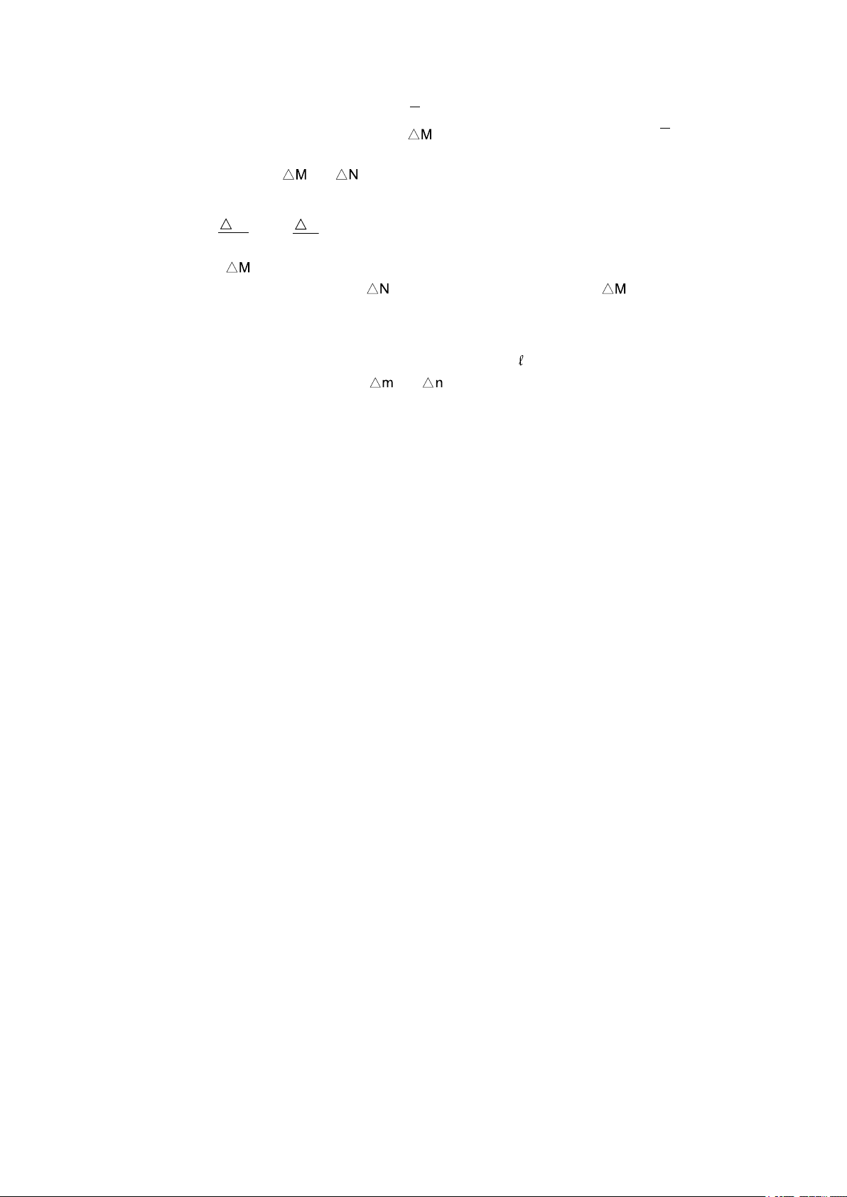
7. CIRCUIT PRINCIPLE
Fig. 7.1 Principle Circuit
C
M
N
MNm
n
m + n +
m •
(7.1)
M
N = n and M = m,
(7.2)
(7.3)
then
therefore, the equation (7.1) leads
M
S
7.1 Basic Principle
The circuit principle of the double bridge is give in Fig. 7.1.
If the current flowing the galvanometer G becomes zero by adjusting the resistance N and n,
the unknown resistance X is expressed in the equation (7.1) where
the resistance of the lead across the terminals Ps of S and Px of X.
represents
G
P1S
M
P2S
P2S
SP
S
X = S +
N
n
P2P1
1
x
Px
C2
m
–
In this double bridge, the resistance armes N and n are equally variable by means of
interlocked dial, and the relation between N, n and M, m are made to be
NMn
–
= 0
m
It is thus possible to measure "X" (low resistance) precisely without being affected by
" (resistance of leads).
"
An unknown resistance X can be read on the N arm dial at the multiplying factor
determined from the ratio of the resistance M against the standard resistance S as
N
X = S
― 17 ―
.
Page 23

IM 2752-01E
7.2 Error
1000
(7.4)
Then the equation (7.1) shall be
If = 0.1 ohm, the equation (7.4) shall become
if S = 10 ohms, (7.1) shall be
S
MNm
n
M
N
X = S S (1+ ) (1- ) = S(1+ - )
N
M
N
(N+ N)
M
N
N
N
M
(7.5)
on condition that,
7.2.1 Error due to current lead resistance
In a practical circuit, the equation (7.2) does not become zero,
-4
but shall be about 10
to 10-5, even though in such a highly accurate bridge as 2752.
For example, m = n, (m =1000 ohms, n = 1000 to 100 ohms) and
m •
m + n +
-3
n
–
MNm
X = × 10 ± 0.5 × 10 ohms
1000
m
m + n
-3
n
•
–
MNm
±0.5 × 10 ohms and
= ± 0.5 × 10
-5
-5
(m + n).
Thus, the error is 0.5% against the reading on the dial.
This means that if the value of
large accordingly, regardless how shall the value
Therefore, care should be taken to the value of
The resistance in the part of
is large, the error shall become
–
may be.
.
corresponding to the distance between Ps and C2 in
this bridge is designed to be nearly zero.
Therefore, the resistance of the lead from C
to Px may be considered as .
2
7.2.2 Error due to potential lead
In this bridge, the arms M, m, N, n are determined in the range of resistance
1000 ohms and 100 ohms, so that the influence from lead resistance can be
negligible in ordinary measurements.
However, if the lead resistance is too large to neglect, the lead resistance connected
the terminals P
and P2 becomes the error of the arms M and N.
1
While, the values of the arms M and M are only influential upon the measuring
-4
result in the from of the ratio
Therefore, if there is a resistance
.
in N, the addition of a resistance to M can
offset the side influence.
(M+ M)
M
N
N
1,
M
M
M
1,
― 18 ―
M
N
Page 24
IM 2752-01E
The 2752 provides the terminals
P and P
2S
P and P
2S
N
N
M
M
The resistance corresponding to the value
2S
for this purpose.
can be connected between
2S
place of the short bar.
The relation between
and to minimize such error is introduced from
the equation (7.5) as follows:
=
Usually, the is less than 0.1 ohm and it is difficult to be replaced with a variable resistor.
In practice the same sort of lead as
is recommendable to put to use as ,
where the length of M is adjusted to an appropriate amount.
There is no terminals provided for the arms m and n as in the case of M and N,
however, the lead resistance can be negligible if the value of
The influence of the lead resistance
and has relation to the equation (7.1) as
is made less than S.
described in Para. 7.2.1.
7.2.3 Error of standard resistor
YOKOGAWA manufactures the standard resistor under a strict quality control,
since such resistance give influences direct upon errors in measurement.
The quality of manganin to be used as the resistance material is of AA class prescribed in
Japanese Industrial Standard, JIS 2522, or of even better than standard.
in
The tolerance of its resistance error at 20°C is made to be within 0.02%.
One of the most importance point to note for the use of this bridge is the change of
resistance by temperature rise.
Follow Para. 6.1 (5) again for an accurate measurement.
Fig.7.2 shows a typical example of temperature characteristics for manganin resistor
used in this bridge.
Accuracy of this resistor is largely depended on the temperature coefficient.
The extent of accuracy drop may be assumed from the example shown in Fig.7.2.
― 19 ―
Page 25

IM 2752-01E
+0.02
+0.01
40
Built-in Standard Resistor
Resistance change (%)
-0.01
-0.02
0
10
15 20 25 30
Temperature (°C)
Fig. 7.2
Typical Example of Temperature Characteristics for
35
0.001 Ω
0.01 Ω
― 20 ―
Page 26
IM 2752-01E
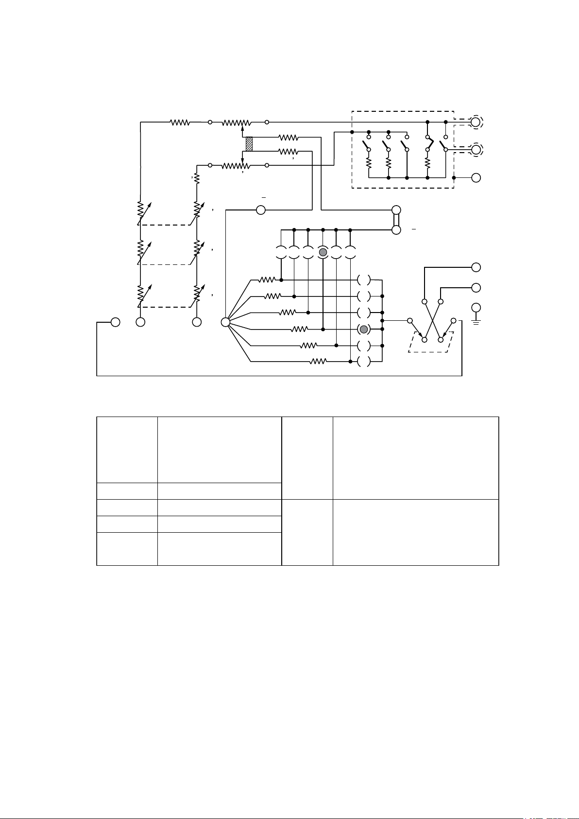
8. CIRCUIT DIAGRAM
G0G
GA GUARD
R
R
R3
R2
R1
S3
S2
S1
6
R 6
R2
R1
R3
P1S
4
R5
S4
R
5
R4
P1S
0.001 0.01 0.1 1 10 100
R 11
12
R
R 13
C 2C 1 P1 P2
R 14
R 15
R 16
K1
R 21
G2
K 2
R 22
G1
K 3
R 23
P2S
P2S
0.001
0.01
0.1
1
10
100
S
GA
K 4
BA
S5
R1, R1’
R2, R2’
R3, R3’
R4, R4’
R5, R5’
R6, R6’
R11 to R16
R21 to R23
Resistor: 1st dial (element)
Resistor: 2nd dial (element)
Resistor: 3rd dial (element)
Resistor: 4th dial (element)
Resistor
Adjusting resistor
Resistor
Resistor
(for Galvanometer)
S1
S2
S3
S4
S5
K1
K2
K3
K4
Switch: Rotary 1
Switch: Rotary 2
Switch: Rotary 3
Switch: Rotary 4
Switch: Knife (Battery)
Switch : Push button (G
Switch : Push button (G1)
Switch : Push button (G
Switch : Push button (G
2)
0
)
S
)
― 21 ―
Page 27

IM 2752-01E
Internal Construction of 2752 Double Bridge
― 22 ―
Page 28

Printed in Japan
 Loading...